EP3276636A1 - Electronic device and image forming device - Google Patents
Electronic device and image forming device Download PDFInfo
- Publication number
- EP3276636A1 EP3276636A1 EP17182624.1A EP17182624A EP3276636A1 EP 3276636 A1 EP3276636 A1 EP 3276636A1 EP 17182624 A EP17182624 A EP 17182624A EP 3276636 A1 EP3276636 A1 EP 3276636A1
- Authority
- EP
- European Patent Office
- Prior art keywords
- resin
- electronic device
- resin layer
- oxygen index
- flammability
- Prior art date
- Legal status (The legal status is an assumption and is not a legal conclusion. Google has not performed a legal analysis and makes no representation as to the accuracy of the status listed.)
- Granted
Links
- 229920005989 resin Polymers 0.000 claims abstract description 196
- 239000011347 resin Substances 0.000 claims abstract description 196
- 229910052760 oxygen Inorganic materials 0.000 claims description 101
- 239000001301 oxygen Substances 0.000 claims description 101
- QVGXLLKOCUKJST-UHFFFAOYSA-N atomic oxygen Chemical compound [O] QVGXLLKOCUKJST-UHFFFAOYSA-N 0.000 claims description 100
- 239000000758 substrate Substances 0.000 claims description 6
- 229920003020 cross-linked polyethylene Polymers 0.000 claims description 4
- 239000004703 cross-linked polyethylene Substances 0.000 claims description 4
- 239000000113 methacrylic resin Substances 0.000 claims description 4
- 238000010030 laminating Methods 0.000 claims description 2
- 230000000149 penetrating effect Effects 0.000 claims 1
- 239000000057 synthetic resin Substances 0.000 description 23
- 229920003002 synthetic resin Polymers 0.000 description 23
- 239000003990 capacitor Substances 0.000 description 21
- 239000000463 material Substances 0.000 description 10
- 238000012360 testing method Methods 0.000 description 10
- 230000006870 function Effects 0.000 description 5
- RNFJDJUURJAICM-UHFFFAOYSA-N 2,2,4,4,6,6-hexaphenoxy-1,3,5-triaza-2$l^{5},4$l^{5},6$l^{5}-triphosphacyclohexa-1,3,5-triene Chemical compound N=1P(OC=2C=CC=CC=2)(OC=2C=CC=CC=2)=NP(OC=2C=CC=CC=2)(OC=2C=CC=CC=2)=NP=1(OC=1C=CC=CC=1)OC1=CC=CC=C1 RNFJDJUURJAICM-UHFFFAOYSA-N 0.000 description 4
- 230000000694 effects Effects 0.000 description 4
- 239000003063 flame retardant Substances 0.000 description 4
- 229910052736 halogen Inorganic materials 0.000 description 4
- 238000011156 evaluation Methods 0.000 description 3
- 150000002367 halogens Chemical class 0.000 description 3
- 238000000034 method Methods 0.000 description 3
- 238000010586 diagram Methods 0.000 description 2
- 239000007789 gas Substances 0.000 description 2
- 238000013021 overheating Methods 0.000 description 2
- WKBOTKDWSSQWDR-UHFFFAOYSA-N Bromine atom Chemical compound [Br] WKBOTKDWSSQWDR-UHFFFAOYSA-N 0.000 description 1
- GDTBXPJZTBHREO-UHFFFAOYSA-N bromine Substances BrBr GDTBXPJZTBHREO-UHFFFAOYSA-N 0.000 description 1
- 229910052794 bromium Inorganic materials 0.000 description 1
- 239000000696 magnetic material Substances 0.000 description 1
- 238000004519 manufacturing process Methods 0.000 description 1
- 238000005259 measurement Methods 0.000 description 1
- 238000000691 measurement method Methods 0.000 description 1
- 239000000155 melt Substances 0.000 description 1
- 150000002894 organic compounds Chemical class 0.000 description 1
- 150000002926 oxygen Chemical class 0.000 description 1
- 230000005236 sound signal Effects 0.000 description 1
- 239000010409 thin film Substances 0.000 description 1
Images


Classifications
-
- H—ELECTRICITY
- H04—ELECTRIC COMMUNICATION TECHNIQUE
- H04R—LOUDSPEAKERS, MICROPHONES, GRAMOPHONE PICK-UPS OR LIKE ACOUSTIC ELECTROMECHANICAL TRANSDUCERS; DEAF-AID SETS; PUBLIC ADDRESS SYSTEMS
- H04R1/00—Details of transducers, loudspeakers or microphones
- H04R1/02—Casings; Cabinets ; Supports therefor; Mountings therein
- H04R1/025—Arrangements for fixing loudspeaker transducers, e.g. in a box, furniture
-
- H—ELECTRICITY
- H05—ELECTRIC TECHNIQUES NOT OTHERWISE PROVIDED FOR
- H05K—PRINTED CIRCUITS; CASINGS OR CONSTRUCTIONAL DETAILS OF ELECTRIC APPARATUS; MANUFACTURE OF ASSEMBLAGES OF ELECTRICAL COMPONENTS
- H05K5/00—Casings, cabinets or drawers for electric apparatus
-
- C—CHEMISTRY; METALLURGY
- C09—DYES; PAINTS; POLISHES; NATURAL RESINS; ADHESIVES; COMPOSITIONS NOT OTHERWISE PROVIDED FOR; APPLICATIONS OF MATERIALS NOT OTHERWISE PROVIDED FOR
- C09K—MATERIALS FOR MISCELLANEOUS APPLICATIONS, NOT PROVIDED FOR ELSEWHERE
- C09K21/00—Fireproofing materials
- C09K21/06—Organic materials
-
- G—PHYSICS
- G03—PHOTOGRAPHY; CINEMATOGRAPHY; ANALOGOUS TECHNIQUES USING WAVES OTHER THAN OPTICAL WAVES; ELECTROGRAPHY; HOLOGRAPHY
- G03G—ELECTROGRAPHY; ELECTROPHOTOGRAPHY; MAGNETOGRAPHY
- G03G21/00—Arrangements not provided for by groups G03G13/00 - G03G19/00, e.g. cleaning, elimination of residual charge
-
- H—ELECTRICITY
- H01—ELECTRIC ELEMENTS
- H01B—CABLES; CONDUCTORS; INSULATORS; SELECTION OF MATERIALS FOR THEIR CONDUCTIVE, INSULATING OR DIELECTRIC PROPERTIES
- H01B7/00—Insulated conductors or cables characterised by their form
- H01B7/17—Protection against damage caused by external factors, e.g. sheaths or armouring
- H01B7/29—Protection against damage caused by extremes of temperature or by flame
-
- H—ELECTRICITY
- H04—ELECTRIC COMMUNICATION TECHNIQUE
- H04R—LOUDSPEAKERS, MICROPHONES, GRAMOPHONE PICK-UPS OR LIKE ACOUSTIC ELECTROMECHANICAL TRANSDUCERS; DEAF-AID SETS; PUBLIC ADDRESS SYSTEMS
- H04R1/00—Details of transducers, loudspeakers or microphones
- H04R1/02—Casings; Cabinets ; Supports therefor; Mountings therein
- H04R1/028—Casings; Cabinets ; Supports therefor; Mountings therein associated with devices performing functions other than acoustics, e.g. electric candles
-
- H—ELECTRICITY
- H04—ELECTRIC COMMUNICATION TECHNIQUE
- H04R—LOUDSPEAKERS, MICROPHONES, GRAMOPHONE PICK-UPS OR LIKE ACOUSTIC ELECTROMECHANICAL TRANSDUCERS; DEAF-AID SETS; PUBLIC ADDRESS SYSTEMS
- H04R9/00—Transducers of moving-coil, moving-strip, or moving-wire type
- H04R9/06—Loudspeakers
Definitions
- the present invention relates to an electronic device including an element in which an electric current flows and an image forming device, and particularly, relates to a technology for handling over heating of an element.
- An electronic device includes an element such as a coil, a heater, or a condenser.
- an element such as a coil, a heater, or a condenser.
- a current fuse, a thermal fuse, and a thermistor are incorporated into an electric circuit of the element. Therefore, when the element is overheated, an electric current that flows in the element is blocked or obstructed.
- a non-flammable material is preferably applied to a frame or a housing of such an electronic device.
- a rubber composition in which both wear resistance and non-flammability are satisfied in high level, and an outer hood for a railway vehicle using such the rubber are suggested.
- An electronic device includes an element, a first member, and a second member. An electric current flows in the element.
- the element is mounted in the first member or the first member is arranged to face the element.
- the first member is made of a first resin.
- the second member is provided adjacent to the first member.
- the second member is made of a second resin.
- one of the first resin and the second resin has lower non-flammability than the other.
- an image forming device includes the above electronic device and an image forming unit configured to form an image in a recording medium.
- Fig. 1 is a schematic diagram showing a configuration of an electronic device according to a first embodiment of the present invention.
- an electronic device 1 of the present embodiment is a small speaker configured to output sound.
- the electronic device 1 includes a voice coil 2, a vibration portion 3 to which the voice coil 2 is attached, a horn unit 4 provided on the outer periphery of the vibration portion 3, and a speaker box 5 supporting the horn unit 4.
- a magnet or a magnetic material (not shown) that generates a magnetic field is arranged in the vicinity of the voice coil 2.
- the voice coil 2 and the vibration portion 3 vibrate to generate sound, and the sound is output from the horn unit 4.
- the voice coil 2 is an example of the element in the claims.
- a first resin having high non-flammability is applied to the vibration portion 3 to which the voice coil 2 is attached, and a countermeasure for overheating of the voice coil 2 is adopted, thereby increasing safety.
- a fire extinguishing component is mixed into the first resin having high non-flammability in order to enhance non-flammability, a self-extinguishing property, and a flame retardant property.
- the vibration portion 3 is an example of a first member in the claims.
- a second resin having non-flammability that is appropriately lower than the first resin is applied to the horn unit 4. Further, any material is applied to the speaker box 5 regardless of high non-flammability or low non-flammability. Thus, the degree of freedom in selecting materials of the horn unit 4 and the speaker box 5 is high.
- the horn unit 4 is an example of a second member in the claims.
- a circular hole is formed in the horn unit 4, the circular vibration portion 3 is fitted into the hole of the horn unit 4, and the horn unit 4 is provided adjacent to the outer periphery of the vibration portion 3.
- This oxygen index is an indicator of non-flammability of a synthetic resin, which will be described below.
- one of the oxygen index A and the oxygen index B may be greater than the other, but it is preferable that the oxygen index A be greater than the oxygen index B as described above. For this reason, description will be provided below on the assumption that the oxygen index A is greater than the oxygen index B.
- the oxygen index A of the first resin In order to set non-flammability of the first resin to be high as described above, it is necessary to set the oxygen index A of the first resin to be sufficiently great, and preferably, it is necessary to set the oxygen index A to be 27 or more.
- non-flammability of the second resin forming the horn unit 4 is set to be appropriately lower than non-flammability of the first resin, this is set not be too low, and thus the horn unit 4 does not easily burn.
- the fire extinguishing component that is included in the first resin in order to enhance non-flammability, a self-extinguishing property, and a flame retardant property is volatilized according to the burning of the first resin forming the vibration portion 3 and influences burning of the second resin forming the horn unit 4. Therefore, the horn unit 4 is effectively prevented from burning
- the electronic device is designed in consideration of not only safety but also mechanical strength, durability, an aesthetic appearance, and costs, if only a synthetic resin having high non-flammability is applied, it is not possible to meet such various demands.
- the electronic device 1 since the degree of freedom in selecting materials of the horn unit 4 and the speaker box 5 is high, it is possible to provide the electronic device 1 which is excellent not only in safety but also mechanical strength, durability, an aesthetic appearance, and costs.
- the above oxygen index is a Japanese Industrial Standards (JIS) oxygen index OI which is an indicator of non-flammability of a synthetic resin.
- JIS oxygen index OI is an indicator representing a percentage of a minimum oxygen concentration necessary for sustaining burning of a synthetic resin. Since the oxygen index OI is 20 in a general air composition, for example, three grades of non-flammability are defined as shown in the table in Fig. 2 based on the vicinity of 20.
- the safety threshold D that is compared with the average value C of the oxygen index A of the first resin and the oxygen index B of the second resin is preset to a specified value within a numeric range of 22 to 27 at which a synthetic resin hardly burns.
- the safety threshold D is set to 23.
- the oxygen index A of the first resin is preferably set to 27 or more.
- UL Underwriters Laboratories
- a horizontal burning test and a vertical burning test are provided according to the UL94 standard.
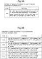
- the horizontal burning test is defined as shown in the table in Fig. 3A .
- the vertical burning test is defined according to five grades as shown in the table in Fig. 3B .
- the average value C of the oxygen indexes A and B is 25 to 27.
- the vibration portion 3 hardly burns, and even if burning of the vibration portion 3 spreads to the horn unit 4, the horn unit 4 does not easily burn, the fire extinguishing component in the vibration portion 3 is volatilized according to burning of the vibration portion 3, and influences burning of the horn unit 4, and the horn unit 4 is effectively prevented from burning.
- the electronic device 1 when the electronic device 1 is designed, if simply the first resin and the second resin are appropriately selected such that the oxygen index A of the first resin forming the vibration portion 3 is greater than the oxygen index B of the second resin forming the horn unit 4, and the average value C of the oxygen index A and the oxygen index B is the safety threshold D or more, it is possible to evaluate and secure safety.
- the first resin is applied to the vibration portion 3 and the second resin is applied to the horn unit 4.
- the first resin may be applied to the vibration portion 3 and the second resin may be applied to the speaker box 5.
- the present invention can be applied to another type of electronic device.
- the first resin is applied a mover or a stator to which a coil is attached, and the second resin is applied to a housing of the motor.
- the first resin is applied to a support member that directly supports a heater
- the second resin is applied to a frame to which the first resin is attached.
- Fig. 5 is a cross-sectional view schematically showing the electronic device according to the second embodiment of the present invention.
- the present embodiment is different from the first embodiment as follows.
- the first member made of the first resin is mounted in the element in which an electric current flows.
- a first member is a first resin layer made of a first resin
- a second member is a second resin layer made of a second resin
- the first resin layer and the second resin layer are laminated as a laminated plate
- the first resin layer as the first member is arranged to face the above element.
- an electronic device 1' of the present embodiment includes a substrate 32, an electrolytic capacitor 33 installed at the substrate 32, and a cover 34 that is arranged to face and apart from the substrate 32 and is made of a synthetic resin.
- the cover 34 is arranged to face the electrolytic capacitor 33.
- a plurality of elements (not shown) are mounted in the substrate 32.
- the electrolytic capacitor 33 and other elements constitute an electronic circuit.
- the electrolytic capacitor 33 is an example of an element in the claims.
- the cover 34 for example, when an overcurrent flows in or an overvoltage is applied to the electrolytic capacitor 33, there is a risk of a combustible material inside the electrolytic capacitor 33 igniting and additionally, there is a concern of fire spreading to the cover 34. Therefore, in the present embodiment, a laminated plate obtained by laminating a first resin layer 11 and a second resin layer 12 is applied as the cover 34, and non-flammability of the cover 34 is enhanced.
- Non-flammability of a resin is represented by an oxygen index.
- the oxygen index A of the first resin layer 11 (that is, the oxygen index A of the first resin) is greater than the oxygen index B of the second resin layer 12 (that is, the oxygen index B of the second resin), and non-flammability of the first resin layer 11 is greater than non-flammability of the second resin layer 12.
- a fire extinguishing component is mixed into the first resin layer 11 in order to enhance non-flammability, a self extinguishing property, and a flame retardant property, the oxygen index A increases and non-flammability thereof is enhanced.
- the first resin layer 11 faces the side on the electrolytic capacitor 33, and the first resin layer 11 is interposed between the second resin layer 12 and the electrolytic capacitor 33.
- a part of the cover 34 melts due to flame of the electrolytic capacitor 33, and a hole 34a is formed in the cover 34.
- a surface 11a of the first resin layer 11 and a surface 12a of the second resin layer 12 are exposed inside the hole 34a, the surface 12a of the second resin layer 12 having low non-flammability is exposed to flame of the electrolytic capacitor 33.
- the fire extinguishing component is volatilized from the surface 11 a of the first resin layer 11, and the surface 12a of the second resin layer 12 is prevented from burning due to the volatilized fire extinguishing component.
- a halogen-based flame retardant such as a bromine-based organic compound
- halogen radicals in a halogen gas volatilized during burning trap and inactivate active radicals generated during a burning reaction
- an oxygen concentration in an atmosphere is reduced due to the halogen gas, and non-flammability is enhanced.
- a surface area of the first resin layer 11 exposed inside the hole 34a is set as S1 and a surface area of the second resin layer 12 exposed inside the hole 34a is set as S2.
- an oxygen index of the first resin layer 11 is set as A
- an oxygen index of the second resin layer 12 is set as B
- the oxygen index A of the first resin layer 11 is set to be greater than the oxygen index B of the second resin layer 12.
- C ′ S 1 ⁇ A + S 2 ⁇ B / 2 S 1 + S 2
- the diameter of the hole 34a is set as r
- the thickness of the first resin layer 11 is set as d1
- the thickness of the second resin layer 12 is set as d2
- the oxygen index A of the first resin layer 11 it is necessary to set the oxygen index A of the first resin layer 11 to be sufficiently great, and preferably, it is necessary to set the oxygen index A to be 27 or more.
- the surface area S1 of the first resin layer 11 inside the hole 34a of the cover 34 becomes wider, a volatilization amount of the fire extinguishing component from the surface of the first resin layer 11 increases.
- the surface area S2 of the second resin layer 12 inside the hole 34a becomes narrower, an effect of preventing burning of the second resin layer 12 due to the fire extinguishing component volatilized from the surface of the first resin layer 11 is enhanced. Therefore, it is necessary to set the surface area S 1 of the first resin layer 11 to be equal to or larger than the surface area S2 of the second resin layer 12 or not to be significantly smaller than the surface area S2 of the second resin layer 12.
- the oxygen index A of the first resin layer 11 is set to 27 or more
- the cover 34 is excellent not only in safety but also mechanical strength, durability, an aesthetic appearance, and costs.
- the above oxygen index is the JIS oxygen index OI which is an indicator of non-flammability of a synthetic resin.
- the JIS oxygen index OI is an indicator representing a percentage of a minimum oxygen concentration necessary for sustaining burning of a synthetic resin. Since the oxygen index OI is 20 in a general air composition, for example, three grades of non-flammability are defined as shown in the table in Fig. 2 based on the vicinity of 20.
- the safety threshold D' that is compared with the value C' derived from Equation (1) is preset to a specified value within a numeric range of 22 to 27 at which a synthetic resin hardly burns.
- the safety threshold D is set to 23.
- the oxygen index A of the first resin layer 11 is preferably set to 27 or more.
- first resin layer 11 and the second resin layer 12 As an indicator for evaluating non-flammability of general synthetic resins, there is the UL94 standard. As described above, a horizontal burning test and a vertical burning test are provided according to the UL94 standard. The horizontal burning test is defined as shown in the table in Fig. 3A . The vertical burning test is defined according to five grades as shown in the table in Fig. 3B .
- the cover 34 hardly burns, and even if the hole 34a is formed in the cover 34, the fire extinguishing component in the first resin layer 11 is volatilized and the second resin layer 12 is prevented from burning due to the volatilized fire extinguishing component.
- the surface area S1 of the first resin layer 11, the surface area S2 of the second resin layer 12, the oxygen index A of the first resin layer 11, and the oxygen index B of the second resin layer 12 are appropriately set so that the value C' derived from Equation (1) is the safety threshold D' or more. Therefore, it is possible to evaluate and secure safety.
- Fig. 7 shows materials related to non-flammability of Lumirror (registered trademark, commercially available from Toray Advanced Film Co., Ltd.) that can be applied for the first resin layer 11.
- Lumirror registered trademark, commercially available from Toray Advanced Film Co., Ltd.
- Lumirror of a type corresponding to V-0 and VTM-0 has high non-flammability, and can be applied for the first resin layer 11.
- the oxygen index of Lumirror is measured by a known oxygen index measurement method or measurement device.
- the measured oxygen index is applied as the oxygen index A of the first resin layer 11 in Equation (1), and other parameters, that is, the surface area S1 of the first resin layer 11, the surface area S2 of the second resin layer 12, and the oxygen index B of the second resin layer 12, may be appropriate set so that the value C' derived from Equation (1) is the safety threshold D' or more.
- a plurality of first resin layers 11 formed by applying Lumirror may be provided.
- the second resin layer 12 is laminated between the two first resin layers 11.
- the surface areas S1 and S2 and the oxygen indexes A and B are set so that the sum of surface areas of the first resin layers 11 inside the hole 34a of the cover 34 is the surface area S1 in Equation (1) and the value C' derived from Equation (1) is the safety threshold D' or more.
- the two first resin layers 11 are provided outside the cover 34, it is possible to easily arrange the first resin layer 11 to face the electrolytic capacitor 33, and it is possible easily manufacture the electronic device 1'.
- a plurality of holes 21 punched out from the top surface to the bottom surface are formed in the first resin layer 11, and burrs 21a are formed around the holes 21 on the bottom surface.
- the cover 34 may be formed by bonding the first resin layer 11 to the bottom surface of the second resin layer 12. Since the burr 21a of the hole 21 of the first resin layer 11 is formed downward, the surface area inside the hole 21 of the first resin layer 11 becomes wider.
- the burr 21a is an example of a protrusion in the claims.
- a hole 22 is formed in the second resin layer 12 through the hole 21 of the first resin layer 11, and the hole 21 of the first resin layer 11 and the hole 22 of the second resin layer 12 overlap.
- the surface area inside the hole 21 of the first resin layer 11 is the surface area S1 in Equation (1) and the surface area S1 inside the hole 21 is wide, an effect of preventing burning of the second resin layer 12 due to the fire extinguishing component volatilized from the surface of the first resin layer 11 is enhanced
- each of the holes 21 in the first resin layer 11 shown in Fig. 8B may be set to be smaller, and the number of holes 21 may increase.
- the holes 22 are formed in the second resin layer 12 through the holes 21 of the first resin layer 11, and the holes 21 of the first resin layer 11 and the holes 22 of the second resin layer 12 overlap. Therefore, the relationship of Equation (1) is established for each of the holes 21 and the holes 22 that overlap, and fire is prevented from spreading to the cover 34.
- the present invention includes an image forming device including the electronic device 1 or the electronic device 1'.
- Fig. 9 is a perspective view showing an exemplary image forming device.
- An image forming device 10 shown in Fig. 9 is, for example, a multifunction machine including a plurality of functions such as a copy function, a printer function, a scanner function, and a facsimile function.
- the image forming device 10 has a schematic configuration that includes an image reading unit 110, an image forming unit 120, a sheet feeding unit 13, and a discharge tray 14.
- the image reading unit 110 reads a document placed on a document placement table 111, and generates image data representing an image of the document.
- the image data is stored in an image memory (not shown).
- the image forming unit 120 forms a toner image on a recording sheet fed from the sheet feeding unit 13 based on the image data stored in the image memory. Then, the toner image formed on the recording sheet is thermally fixed by a fixing unit (not shown). The recording sheet on which the image is formed and for which the fixing process is completed is discharged to the discharge tray 14.
- the above speaker of the electronic device 1 is applied.
- the above motor of the electronic device 1 is applied.
- the above heater of the electronic device 1 can be applied.
- the image forming device 10 it is possible to apply the configuration of the electronic device 1' as a power supply thereof, and it is possible to obtain the same operational effect as in the electronic device 1'.
Landscapes
- Engineering & Computer Science (AREA)
- Physics & Mathematics (AREA)
- Chemical & Material Sciences (AREA)
- Acoustics & Sound (AREA)
- Signal Processing (AREA)
- General Physics & Mathematics (AREA)
- Materials Engineering (AREA)
- Organic Chemistry (AREA)
- Microelectronics & Electronic Packaging (AREA)
- Casings For Electric Apparatus (AREA)
- Compositions Of Macromolecular Compounds (AREA)
- Fire Alarms (AREA)
Abstract
Description
- The present invention relates to an electronic device including an element in which an electric current flows and an image forming device, and particularly, relates to a technology for handling over heating of an element.
- An electronic device includes an element such as a coil, a heater, or a condenser. In order to respond to a case in which an overcurrent flows in the element, for example, a current fuse, a thermal fuse, and a thermistor are incorporated into an electric circuit of the element. Therefore, when the element is overheated, an electric current that flows in the element is blocked or obstructed.
- In addition, a non-flammable material is preferably applied to a frame or a housing of such an electronic device. For example, though it is not used for an electronic device, a rubber composition in which both wear resistance and non-flammability are satisfied in high level, and an outer hood for a railway vehicle using such the rubber are suggested.
- According to an aspect of the present invention, a technology that further improves the above technology is proposed.
- An electronic device according to an aspect of the present invention includes an element, a first member, and a second member. An electric current flows in the element. The element is mounted in the first member or the first member is arranged to face the element. In addition, the first member is made of a first resin. The second member is provided adjacent to the first member. In addition, the second member is made of a second resin. In addition, one of the first resin and the second resin has lower non-flammability than the other.
- In addition, an image forming device according to another aspect of the present invention includes the above electronic device and an image forming unit configured to form an image in a recording medium.
-
-
Fig. 1 is a schematic diagram showing a configuration of an electronic device according to a first embodiment of the present invention. -
Fig. 2 is a table showing the definition of three grades of non-flammability based on the JIS oxygen index. -
Fig. 3A is a table showing the definition of non-flammability based on the UL94 standard for a horizontal burning test. -
Fig. 3B is a table showing the definition of non-flammability based on the UL94 standard for a vertical burning test. -
Fig. 4 is a table showing the oxygen index OI for general synthetic resins and evaluation according to the UL94 standard. -
Fig. 5 is a cross-sectional view schematically showing an electronic device according to a second embodiment of the present invention. -
Fig. 6 is a cross-sectional view showing a state in which a hole is formed in a cover of the electronic device inFig. 5 . -
Fig. 7 is a table showing materials related to non-flammability of Lumirror (registered trademark). -
Fig. 8A is a cross-sectional view schematically showing a modified example of the electronic device. -
Fig. 8B is a cross-sectional view schematically showing another modified example of the electronic device. -
Fig. 9 is a perspective view showing an image forming device including the above electronic device and the like. - Embodiments of the present invention will be described below with reference to the drawings.
-
Fig. 1 is a schematic diagram showing a configuration of an electronic device according to a first embodiment of the present invention. As shown inFig. 1 , anelectronic device 1 of the present embodiment is a small speaker configured to output sound. Theelectronic device 1 includes avoice coil 2, avibration portion 3 to which thevoice coil 2 is attached, ahorn unit 4 provided on the outer periphery of thevibration portion 3, and aspeaker box 5 supporting thehorn unit 4. A magnet or a magnetic material (not shown) that generates a magnetic field is arranged in the vicinity of thevoice coil 2. When an audio signal is supplied to thevoice coil 2, thevoice coil 2 and thevibration portion 3 vibrate to generate sound, and the sound is output from thehorn unit 4. Here, thevoice coil 2 is an example of the element in the claims. - In the
electronic device 1, for example, there is a risk of short-circuiting of thevoice coil 2 and an overcurrent flowing in thevoice coil 2. Therefore, in the present embodiment, a first resin having high non-flammability is applied to thevibration portion 3 to which thevoice coil 2 is attached, and a countermeasure for overheating of thevoice coil 2 is adopted, thereby increasing safety. Generally, a fire extinguishing component is mixed into the first resin having high non-flammability in order to enhance non-flammability, a self-extinguishing property, and a flame retardant property. Here, thevibration portion 3 is an example of a first member in the claims. - In addition, a second resin having non-flammability that is appropriately lower than the first resin is applied to the
horn unit 4. Further, any material is applied to thespeaker box 5 regardless of high non-flammability or low non-flammability. Thus, the degree of freedom in selecting materials of thehorn unit 4 and thespeaker box 5 is high. Here, thehorn unit 4 is an example of a second member in the claims. - In addition, a circular hole is formed in the
horn unit 4, thecircular vibration portion 3 is fitted into the hole of thehorn unit 4, and thehorn unit 4 is provided adjacent to the outer periphery of thevibration portion 3. - Specifically, in the present embodiment, when an oxygen index of the first resin forming the
vibration portion 3 is set as A and an oxygen index of the second resin forming thehorn unit 4 is set as B, the oxygen indexes A and B are set so that the oxygen index A is greater than the oxygen index B and an average value C(=[(A+B)/2]) of the oxygen indexes A and B is the preset safety threshold D(=23) or more. This oxygen index is an indicator of non-flammability of a synthetic resin, which will be described below. In addition, one of the oxygen index A and the oxygen index B may be greater than the other, but it is preferable that the oxygen index A be greater than the oxygen index B as described above. For this reason, description will be provided below on the assumption that the oxygen index A is greater than the oxygen index B. - In order to set non-flammability of the first resin to be high as described above, it is necessary to set the oxygen index A of the first resin to be sufficiently great, and preferably, it is necessary to set the oxygen index A to be 27 or more.
- In addition, in order to set non-flammability of the second resin to be appropriately lower than that of the first resin as described above, it is necessary to set the oxygen index B of the second resin not to be too small and set the average value C to be the safety threshold D (=23) or more.
- Therefore, in the
electronic device 1 of the present embodiment, the second resin forming thehorn unit 4 is provided adjacent to the first resin forming thevibration portion 3, the type of the first resin and the second resin is appropriately selected, the oxygen index A of the first resin is set to be sufficiently great, the oxygen index B of the second resin is set not to be too small, and the average value C is set to the safety threshold D (=23) or more. - Therefore, in a short-circuiting portion of the
voice coil 2, a burning range and a burning time of thevibration portion 3 due to the short-circuiting are minimized. - In addition, while non-flammability of the second resin forming the
horn unit 4 is set to be appropriately lower than non-flammability of the first resin, this is set not be too low, and thus thehorn unit 4 does not easily burn. Thus, even if burning of thevibration portion 3 spreads to thehorn unit 4 adjacent to thevibration portion 3, the fire extinguishing component that is included in the first resin in order to enhance non-flammability, a self-extinguishing property, and a flame retardant property is volatilized according to the burning of the first resin forming thevibration portion 3 and influences burning of the second resin forming thehorn unit 4. Therefore, thehorn unit 4 is effectively prevented from burning - Furthermore, since burning caused by short-circuiting in the
voice coil 2 is prevented in thevibration portion 3 and thehorn unit 4, the burning does not spread to thespeaker box 5 outside thehorn unit 4, and thespeaker box 5 does not burn. - Here, there are various types of synthetic resins applied as general materials for a frame or a housing of an electronic device. These synthetic resins are classified into a plurality of groups in consideration of non-flammability. Thus, in order to improve safety of the electronic device, it is desirable that a synthetic resin that has been evaluated to have high non-flammability be applied to an important portion.
- However, since the electronic device is designed in consideration of not only safety but also mechanical strength, durability, an aesthetic appearance, and costs, if only a synthetic resin having high non-flammability is applied, it is not possible to meet such various demands.
- On the other hand, in the present embodiment, since the degree of freedom in selecting materials of the
horn unit 4 and thespeaker box 5 is high, it is possible to provide theelectronic device 1 which is excellent not only in safety but also mechanical strength, durability, an aesthetic appearance, and costs. - Here, the above oxygen index is a Japanese Industrial Standards (JIS) oxygen index OI which is an indicator of non-flammability of a synthetic resin. The JIS oxygen index OI is an indicator representing a percentage of a minimum oxygen concentration necessary for sustaining burning of a synthetic resin. Since the oxygen index OI is 20 in a general air composition, for example, three grades of non-flammability are defined as shown in the table in
Fig. 2 based on the vicinity of 20. - As can be clearly understood from the table in
Fig. 2 , when the oxygen index OI is 22 or less, a synthetic resin burns, when the oxygen index OI is within a numeric range of 22 to 27, a synthetic resin hardly burns, and when the oxygen index OI is 27 or more, a synthetic resin extremely hardly buns. Thus, when the oxygen index OI is 22 or more, safety is thought to be secured. - Therefore, in the present embodiment, the safety threshold D that is compared with the average value C of the oxygen index A of the first resin and the oxygen index B of the second resin is preset to a specified value within a numeric range of 22 to 27 at which a synthetic resin hardly burns. For example, the safety threshold D is set to 23. In addition, the oxygen index A of the first resin is preferably set to 27 or more.
- On the other hand, as an indicator for evaluating non-flammability of general synthetic resins, there is the Underwriters Laboratories (UL) 94 standard. A horizontal burning test and a vertical burning test are provided according to the UL94 standard. The horizontal burning test is defined as shown in the table in
Fig. 3A . The vertical burning test is defined according to five grades as shown in the table inFig. 3B . - Here, evaluations of general synthetic resins based on the oxygen index OI and the UL94 standard are shown in the table in
Fig. 4 . - As can be clearly understood from the table in
Fig. 4 , as the oxygen index OI increases, non-flammability according to the UL94 standard tends to increase. Based on the table inFig. 4 , for example, when a crosslinked polyethylene (the oxygen index B=34 to 36) is selected as the first resin forming thevibration portion 3, and a methacrylic resin (the oxygen index A=17 to 18) is selected as the second resin forming thehorn unit 4, the average value C of the oxygen indexes A and B is 25 to 27. The average value is the safety threshold D (=23) or more and the oxygen index A of the first resin is 27 or more. Thus, as described above, even if thevoice coil 2 is overheated due to short-circuiting, thevibration portion 3 hardly burns, and even if burning of thevibration portion 3 spreads to thehorn unit 4, thehorn unit 4 does not easily burn, the fire extinguishing component in thevibration portion 3 is volatilized according to burning of thevibration portion 3, and influences burning of thehorn unit 4, and thehorn unit 4 is effectively prevented from burning. - In addition, when the
electronic device 1 is designed, if simply the first resin and the second resin are appropriately selected such that the oxygen index A of the first resin forming thevibration portion 3 is greater than the oxygen index B of the second resin forming thehorn unit 4, and the average value C of the oxygen index A and the oxygen index B is the safety threshold D or more, it is possible to evaluate and secure safety. - Here, in the above embodiment, since the
horn unit 4 is provided adjacent to the outer periphery of thevibration portion 3, the first resin is applied to thevibration portion 3 and the second resin is applied to thehorn unit 4. However, in a configuration in which thehorn unit 4 is omitted and thevibration portion 3 is attached to a hole of thespeaker box 5, the first resin may be applied to thevibration portion 3 and the second resin may be applied to thespeaker box 5. - In addition, while the speaker has been exemplified as the electronic device of the present embodiment, the present invention can be applied to another type of electronic device. For example, in a motor, the first resin is applied a mover or a stator to which a coil is attached, and the second resin is applied to a housing of the motor.
- Alternatively, the first resin is applied to a support member that directly supports a heater, and the second resin is applied to a frame to which the first resin is attached.
- Next, an electronic device according to a second embodiment of the present invention will be described in detail with reference to
Fig. 5. Fig. 5 is a cross-sectional view schematically showing the electronic device according to the second embodiment of the present invention. Here, the present embodiment is different from the first embodiment as follows. In the first embodiment, the first member made of the first resin is mounted in the element in which an electric current flows. On the other hand, in the present embodiment, a first member is a first resin layer made of a first resin, a second member is a second resin layer made of a second resin, the first resin layer and the second resin layer are laminated as a laminated plate, and the first resin layer as the first member is arranged to face the above element. - As shown in
Fig. 5 , an electronic device 1' of the present embodiment includes asubstrate 32, anelectrolytic capacitor 33 installed at thesubstrate 32, and acover 34 that is arranged to face and apart from thesubstrate 32 and is made of a synthetic resin. Thecover 34 is arranged to face theelectrolytic capacitor 33. In addition to theelectrolytic capacitor 33, a plurality of elements (not shown) are mounted in thesubstrate 32. Theelectrolytic capacitor 33 and other elements constitute an electronic circuit. Here, theelectrolytic capacitor 33 is an example of an element in the claims. - In the electronic device 1', for example, when an overcurrent flows in or an overvoltage is applied to the
electrolytic capacitor 33, there is a risk of a combustible material inside theelectrolytic capacitor 33 igniting and additionally, there is a concern of fire spreading to thecover 34. Therefore, in the present embodiment, a laminated plate obtained by laminating afirst resin layer 11 and asecond resin layer 12 is applied as thecover 34, and non-flammability of thecover 34 is enhanced. - Non-flammability of a resin is represented by an oxygen index. The oxygen index A of the first resin layer 11 (that is, the oxygen index A of the first resin) is greater than the oxygen index B of the second resin layer 12 (that is, the oxygen index B of the second resin), and non-flammability of the
first resin layer 11 is greater than non-flammability of thesecond resin layer 12. A fire extinguishing component is mixed into thefirst resin layer 11 in order to enhance non-flammability, a self extinguishing property, and a flame retardant property, the oxygen index A increases and non-flammability thereof is enhanced. - In addition, the
first resin layer 11 faces the side on theelectrolytic capacitor 33, and thefirst resin layer 11 is interposed between thesecond resin layer 12 and theelectrolytic capacitor 33. - Here, when the
electrolytic capacitor 33 ignites, since thefirst resin layer 11 having high non-flammability faces the side on theelectrolytic capacitor 33, thecover 34 hardly burns. - However, as shown in
Fig. 6 , a part of thecover 34 melts due to flame of theelectrolytic capacitor 33, and ahole 34a is formed in thecover 34. In this case, since asurface 11a of thefirst resin layer 11 and asurface 12a of thesecond resin layer 12 are exposed inside thehole 34a, thesurface 12a of thesecond resin layer 12 having low non-flammability is exposed to flame of theelectrolytic capacitor 33. - However, since the
surface 11 a of thefirst resin layer 11 is also exposed to flame of theelectrolytic capacitor 33, the fire extinguishing component is volatilized from thesurface 11 a of thefirst resin layer 11, and thesurface 12a of thesecond resin layer 12 is prevented from burning due to the volatilized fire extinguishing component. For example, it is known that, when a halogen-based flame retardant such as a bromine-based organic compound is added to a resin, halogen radicals in a halogen gas volatilized during burning trap and inactivate active radicals generated during a burning reaction, an oxygen concentration in an atmosphere is reduced due to the halogen gas, and non-flammability is enhanced. - In addition, as the area of the
surface 11 a of thefirst resin layer 11 becomes wider, a volatilization amount of the fire extinguishing component in thefirst resin layer 11 increases. As the area of thesurface 12a of thesecond resin layer 12 becomes narrower, an effect of preventing burning of thesurface 12a of thesecond resin layer 12 due to the fire extinguishing component volatilized from thesurface 11a of thefirst resin layer 11 is enhanced. For this reason, it is desirable to appropriately set the area of thesurface 11 a of thefirst resin layer 11 and the area of thesurface 12a of thesecond resin layer 12. - Specifically, in the present embodiment, while the
hole 34a is formed in thecover 34 due to flame of theelectrolytic capacitor 33, a surface area of thefirst resin layer 11 exposed inside thehole 34a is set as S1 and a surface area of thesecond resin layer 12 exposed inside thehole 34a is set as S2. - In addition, an oxygen index of the
first resin layer 11 is set as A, an oxygen index of thesecond resin layer 12 is set as B, and the oxygen index A of thefirst resin layer 11 is set to be greater than the oxygen index B of thesecond resin layer 12. - Then, the surface area S1 of the
first resin layer 11, the surface area S2 of thesecond resin layer 12, the oxygen index A of thefirst resin layer 11, and the oxygen index B of thesecond resin layer 12 are set so that the value C' derived from the following Equation (1) is the preset safety threshold D'(=23) or more.
- Here, when the
hole 34a of thecover 34 is assumed to be substantially circular, the diameter of thehole 34a is set as r, the thickness of thefirst resin layer 11 is set as d1, and the thickness of thesecond resin layer 12 is set as d2, the surface area S1 of thefirst resin layer 11 can be approximated from S1=πr×d1, and the surface area S2 of thesecond resin layer 12 can be approximated from S2=πr×d2. - Here, in order to set non-flammability of the
first resin layer 11 to be high as described above, it is necessary to set the oxygen index A of thefirst resin layer 11 to be sufficiently great, and preferably, it is necessary to set the oxygen index A to be 27 or more. - In addition, it is necessary to set the oxygen index B of the
second resin layer 12 not to be small while non-flammability of thesecond resin layer 12 is set to be lower than that of thefirst resin layer 11 as described above. - Furthermore, as the surface area S1 of the
first resin layer 11 inside thehole 34a of thecover 34 becomes wider, a volatilization amount of the fire extinguishing component from the surface of thefirst resin layer 11 increases. As the surface area S2 of thesecond resin layer 12 inside thehole 34a becomes narrower, an effect of preventing burning of thesecond resin layer 12 due to the fire extinguishing component volatilized from the surface of thefirst resin layer 11 is enhanced. Therefore, it is necessary to set thesurface area S 1 of thefirst resin layer 11 to be equal to or larger than the surface area S2 of thesecond resin layer 12 or not to be significantly smaller than the surface area S2 of thesecond resin layer 12. - For example, when the
surface area S 1 of thefirst resin layer 11 and the surface area S2 of thesecond resin layer 12 are set to be equal to each other, Equation (1) is C'=(A+B)/2, the oxygen index A of thefirst resin layer 11 is set to 27 or more and the oxygen index B of the second resin layer is set not to be too small so that the value C' is the safety threshold D'(=23) or more. That is, when the surface area S1 and the surface area S2 are set to be equal to each other, the value C' obtained from Equation (1) is the average value of the oxygen index A and the oxygen index B, that is, the average value C in the first embodiment as described above. - Then, when the
surface area S 1 of thefirst resin layer 11 is set to be narrower than the surface area S2 of thesecond resin layer 12, in order to set the value C' to be the safety threshold D'(=23) or more, it is necessary to set either of the oxygen index A of thefirst resin layer 11 and the oxygen index B of the second resin layer to be greater. - Accordingly, as shown in
Fig. 6 , even if thehole 34a is formed in thecover 34 due to ignition of theelectrolytic capacitor 33, thesurface 11a of thefirst resin layer 11 inside thehole 34a does not burn, and burning of thesurface 12a of thesecond resin layer 12 inside thehole 34a is effectively prevented due to the fire extinguishing component volatilized from the surface of thefirst resin layer 11, and it is possible to prevent fire spreading of thecover 34 itself. - In addition, since it is not necessary for the
second resin layer 12 to emphasize the degree of non-flammability like thefirst resin layer 11, and the degree of freedom in selecting a material thereof is high, it is possible to provide thecover 34 that is excellent not only in safety but also mechanical strength, durability, an aesthetic appearance, and costs. - Next, the above safety threshold D' will be described. As described above, the above oxygen index is the JIS oxygen index OI which is an indicator of non-flammability of a synthetic resin. The JIS oxygen index OI is an indicator representing a percentage of a minimum oxygen concentration necessary for sustaining burning of a synthetic resin. Since the oxygen index OI is 20 in a general air composition, for example, three grades of non-flammability are defined as shown in the table in
Fig. 2 based on the vicinity of 20. - As can be clearly understood from the table in
Fig. 2 , when the oxygen index OI is 22 or less, a synthetic resin burns, when the oxygen index OI is within a numeric range of 22 to 27, a synthetic resin hardly burns, and when the oxygen index OI is 27 or more, a synthetic resin extremely hardly buns. Thus, when the oxygen index OI is 22 or more, safety is thought to be secured. - Therefore, in the present embodiment, the safety threshold D' that is compared with the value C' derived from Equation (1) is preset to a specified value within a numeric range of 22 to 27 at which a synthetic resin hardly burns. For example, the safety threshold D is set to 23. In addition, the oxygen index A of the
first resin layer 11 is preferably set to 27 or more. - Next, specific examples of the
first resin layer 11 and thesecond resin layer 12 will be described. As an indicator for evaluating non-flammability of general synthetic resins, there is the UL94 standard. As described above, a horizontal burning test and a vertical burning test are provided according to the UL94 standard. The horizontal burning test is defined as shown in the table inFig. 3A . The vertical burning test is defined according to five grades as shown in the table inFig. 3B . - Here, evaluations of general synthetic resins based on the oxygen index OI and the UL94 standard are shown in the table in
Fig. 4 as described above. - As can be clearly understood from the table in
Fig. 4 , as the oxygen index OI increases, non-flammability according to the UL94 standard tends to increase. Based on the table inFig. 4 , for example, when a crosslinked polyethylene (the oxygen index B=34 to 36) is selected as thefirst resin layer 11, and a methacrylic resin (the oxygen index A=17 to 18) is selected as thesecond resin layer 12, and the surface area S1 of thefirst resin layer 11 and the surface area S2 of thesecond resin layer 12 are equal to each other, the value C' derived from Equation (1) is 25 to 27, the value C' is the safety threshold D'(=23) or more, and the oxygen index A of thefirst resin layer 11 is 27 or more. Therefore, as described above, even if theelectrolytic capacitor 33 ignites and flame of theelectrolytic capacitor 33 is exposed to thesurface 11a of thefirst resin layer 11, thecover 34 hardly burns, and even if thehole 34a is formed in thecover 34, the fire extinguishing component in thefirst resin layer 11 is volatilized and thesecond resin layer 12 is prevented from burning due to the volatilized fire extinguishing component. - In addition, when the electronic device 1' is designed, the surface area S1 of the
first resin layer 11, the surface area S2 of thesecond resin layer 12, the oxygen index A of thefirst resin layer 11, and the oxygen index B of thesecond resin layer 12 are appropriately set so that the value C' derived from Equation (1) is the safety threshold D' or more. Therefore, it is possible to evaluate and secure safety. -
Fig. 7 shows materials related to non-flammability of Lumirror (registered trademark, commercially available from Toray Advanced Film Co., Ltd.) that can be applied for thefirst resin layer 11. - According to the materials in
Fig. 7 , Lumirror of a type corresponding to V-0 and VTM-0 has high non-flammability, and can be applied for thefirst resin layer 11. - Here, while an oxygen index of Lumirror is not described, the oxygen index of Lumirror is measured by a known oxygen index measurement method or measurement device. The measured oxygen index is applied as the oxygen index A of the
first resin layer 11 in Equation (1), and other parameters, that is, the surface area S1 of thefirst resin layer 11, the surface area S2 of thesecond resin layer 12, and the oxygen index B of thesecond resin layer 12, may be appropriate set so that the value C' derived from Equation (1) is the safety threshold D' or more. - However, most of Lumirror has a thin film form. Therefore, as shown in
Fig. 8A , a plurality of first resin layers 11 formed by applying Lumirror may be provided. For example, as shown inFig. 8A , in thecover 34, thesecond resin layer 12 is laminated between the two first resin layers 11. In this case, the surface areas S1 and S2, and the oxygen indexes A and B are set so that the sum of surface areas of the first resin layers 11 inside thehole 34a of thecover 34 is the surface area S1 in Equation (1) and the value C' derived from Equation (1) is the safety threshold D' or more. In addition, as described above, since the two first resin layers 11 are provided outside thecover 34, it is possible to easily arrange thefirst resin layer 11 to face theelectrolytic capacitor 33, and it is possible easily manufacture the electronic device 1'. - Alternatively, as shown in
Fig. 8B , a plurality ofholes 21 punched out from the top surface to the bottom surface are formed in thefirst resin layer 11, andburrs 21a are formed around theholes 21 on the bottom surface. Then, thecover 34 may be formed by bonding thefirst resin layer 11 to the bottom surface of thesecond resin layer 12. Since theburr 21a of thehole 21 of thefirst resin layer 11 is formed downward, the surface area inside thehole 21 of thefirst resin layer 11 becomes wider. Here, theburr 21a is an example of a protrusion in the claims. - In this case, due to ignition of the
electrolytic capacitor 33, ahole 22 is formed in thesecond resin layer 12 through thehole 21 of thefirst resin layer 11, and thehole 21 of thefirst resin layer 11 and thehole 22 of thesecond resin layer 12 overlap. In this case, since the surface area inside thehole 21 of thefirst resin layer 11 is the surface area S1 in Equation (1) and the surface area S1 inside thehole 21 is wide, an effect of preventing burning of thesecond resin layer 12 due to the fire extinguishing component volatilized from the surface of thefirst resin layer 11 is enhanced - Furthermore, the diameter of each of the
holes 21 in thefirst resin layer 11 shown inFig. 8B may be set to be smaller, and the number ofholes 21 may increase. In this case, due to ignition of theelectrolytic capacitor 33, theholes 22 are formed in thesecond resin layer 12 through theholes 21 of thefirst resin layer 11, and theholes 21 of thefirst resin layer 11 and theholes 22 of thesecond resin layer 12 overlap. Therefore, the relationship of Equation (1) is established for each of theholes 21 and theholes 22 that overlap, and fire is prevented from spreading to thecover 34. - Furthermore, the present invention includes an image forming device including the
electronic device 1 or the electronic device 1'.Fig. 9 is a perspective view showing an exemplary image forming device. Animage forming device 10 shown inFig. 9 is, for example, a multifunction machine including a plurality of functions such as a copy function, a printer function, a scanner function, and a facsimile function. Theimage forming device 10 has a schematic configuration that includes animage reading unit 110, animage forming unit 120, asheet feeding unit 13, and adischarge tray 14. - When the
image forming device 10 performs an image reading operation, theimage reading unit 110 reads a document placed on a document placement table 111, and generates image data representing an image of the document. The image data is stored in an image memory (not shown). - When the
image forming device 10 performs an image forming operation, theimage forming unit 120 forms a toner image on a recording sheet fed from thesheet feeding unit 13 based on the image data stored in the image memory. Then, the toner image formed on the recording sheet is thermally fixed by a fixing unit (not shown). The recording sheet on which the image is formed and for which the fixing process is completed is discharged to thedischarge tray 14. - In the
image forming device 10, in order to produce a sound message or an error sound, the above speaker of theelectronic device 1 is applied. In order to drive a plurality of rollers by which a recording sheet is transferred and discharged, the above motor of theelectronic device 1 is applied. Furthermore, in order to thermally fix a recording sheet, the above heater of theelectronic device 1 can be applied. - In addition, in the
image forming device 10, it is possible to apply the configuration of the electronic device 1' as a power supply thereof, and it is possible to obtain the same operational effect as in the electronic device 1'. - In addition, in the above embodiments, the configuration and the process described with reference to
Fig. 1 to Fig. 9 are only one embodiment of the present invention, and the present invention is not limited to the configuration and the process.
Claims (20)
- An electronic device comprising:an element (2, 33) in which an electric current flows;a first member (3, 11) in which the element (2, 33) is mounted or which is arranged to face the element (2, 33) and which is made of a first resin; anda second member (4, 5, 12) that is provided adjacent to the first member (3, 11) and made of a second resin,wherein one of the first resin and the second resin has lower non-flammability than the other.
- The electronic device according to claim 1, wherein
the element (2) is mounted in the first member (3), and
when an oxygen index of the first resin is set as A and an oxygen index of the second resin is set as B, the oxygen indexes A and B are set so that an average value C of the oxygen indexes A and B is a preset safety threshold D or more. - The electronic device according to claim 2, wherein
the second resin has lower non-flammability than the first resin, and
the oxygen index A is greater than the oxygen index B. - The electronic device according to claim 2 or 3, wherein the safety threshold D is a specified value within a numeric range of 22 to 27.
- The electronic device according to claim 4, wherein the safety threshold D is 23.
- The electronic device according to any one of claims 2 to 4, wherein the oxygen index A is 27 or more.
- The electronic device according to any one of claims 2 to 6, wherein
the element (2) is a voice coil of a speaker,
the first member (3) is a vibration portion in which the voice coil is provided, and
the second member (4, 5) is a horn or a speaker box that is provided adjacent to the vibration portion. - The electronic device according to any one of claims 2 to 6, wherein the element (2) is a coil of a motor.
- The electronic device according to any one of claims 2 to 6, wherein the element (2) is a heater.
- The electronic device according to any one of claims 2 to 9, wherein
the first resin is a crosslinked polyethylene, and
the second resin is a methacrylic resin. - The electronic device according to claim 1, wherein
the first member (11) is a first resin layer that is arranged to face the element (33) and is made of the first resin,
the second member (12) is a second resin layer that is made of the second resin,
the electronic device further comprises a laminated plate (34) obtained by laminating the first resin layer and the second resin layer,
the second resin layer has lower non-flammability than the first resin layer, and
when a hole (34a) is formed in the laminated plate (34) in a direction penetrating the laminated plate (34) from the element (33), if a surface area of the first resin layer exposed inside the hole (34a) is set as S1, a surface area of the second resin layer exposed inside the hole (34a) is set as S2, an oxygen index of the first resin layer is set as A, and an oxygen index of the second resin layer is set as B, the surface areas S1 and S2 and the oxygen indexes A and B are set so that a value C' derived from the following Equation (1) is a preset safety threshold D' or more.
- The electronic device according to claim 11, wherein the oxygen index A is greater than the oxygen index B.
- The electronic device according to claim 11 or 12, wherein the safety threshold D' is a specified value within a numeric range of 22 to 27.
- The electronic device according to claim 13, wherein the safety threshold D' is 23.
- The electronic device according to any one of claims 11 to 14, wherein the oxygen index A is 27 or more.
- The electronic device according to any one of claims 11 to 15, wherein the element (33) is a condenser installed on a substrate, and
the laminated plate (34) is a cover that is arranged to face and apart from the substrate. - The electronic device according to any one of claims 11 to 16, wherein the first resin is a crosslinked polyethylene, and
the second resin is a methacrylic resin. - The electronic device according to any one of claims 11 to 17, wherein, in the laminated plate (34), the second resin layer is laminated between the two first resin layers.
- The electronic device according to any one of claims 11 to 18, wherein a protrusion (21 a) that protrudes toward the element (33) is provided in the first resin layer.
- An image forming device comprising:the electronic device (1, 1') according to any one of claims 1 to 19; andan image forming unit (120) configured to form an image in a recording medium.
Applications Claiming Priority (2)
| Application Number | Priority Date | Filing Date | Title |
|---|---|---|---|
| JP2016145681A JP2018018861A (en) | 2016-07-25 | 2016-07-25 | Electronic device and image forming apparatus |
| JP2016211830A JP2018073979A (en) | 2016-10-28 | 2016-10-28 | Electronic apparatus and image formation device |
Publications (2)
| Publication Number | Publication Date |
|---|---|
| EP3276636A1 true EP3276636A1 (en) | 2018-01-31 |
| EP3276636B1 EP3276636B1 (en) | 2023-06-07 |
Family
ID=59592809
Family Applications (1)
| Application Number | Title | Priority Date | Filing Date |
|---|---|---|---|
| EP17182624.1A Active EP3276636B1 (en) | 2016-07-25 | 2017-07-21 | Electronic device |
Country Status (3)
| Country | Link |
|---|---|
| US (1) | US10237635B2 (en) |
| EP (1) | EP3276636B1 (en) |
| CN (1) | CN107660088B (en) |
Families Citing this family (1)
| Publication number | Priority date | Publication date | Assignee | Title |
|---|---|---|---|---|
| KR102239779B1 (en) * | 2020-08-20 | 2021-04-13 | 에스케이씨하이테크앤마케팅(주) | Display apparatus and optical composite sheet used therefor |
Citations (7)
| Publication number | Priority date | Publication date | Assignee | Title |
|---|---|---|---|---|
| EP1001435A2 (en) * | 1998-11-09 | 2000-05-17 | Yazaki Corporation | Non-halogenated flame-retarded covered wire |
| EP1365421A1 (en) * | 2001-01-24 | 2003-11-26 | Totoku Electric Co., Ltd. | Ceramic insulation coated electric wire, self-fusing ceremic insulation coated electric wire, coating composition, and coil and voice coil for speaker |
| JP2009093837A (en) * | 2007-10-04 | 2009-04-30 | Furukawa Electric Co Ltd:The | Multilayer insulation wire |
| US20110144244A1 (en) * | 2009-12-15 | 2011-06-16 | Apple Inc. | Halogen-free flame retardant material |
| WO2015080005A1 (en) * | 2013-11-28 | 2015-06-04 | Canon Kabushiki Kaisha | Flame retardant composition |
| JP2015170389A (en) * | 2014-03-04 | 2015-09-28 | 日立金属株式会社 | cable |
| WO2016030865A1 (en) * | 2014-08-29 | 2016-03-03 | Zinniatek Limited | Fire retarding system and protective layers or coatings |
Family Cites Families (6)
| Publication number | Priority date | Publication date | Assignee | Title |
|---|---|---|---|---|
| JP3741379B2 (en) * | 1994-05-13 | 2006-02-01 | 日立電線株式会社 | Fireproof cable |
| JP3677886B2 (en) * | 1996-09-05 | 2005-08-03 | 松下電器産業株式会社 | Speaker damper and method of manufacturing the same |
| US7244501B2 (en) * | 2004-03-26 | 2007-07-17 | Azdel, Inc. | Fiber reinforced thermoplastic sheets with surface coverings |
| JP4572678B2 (en) | 2004-12-22 | 2010-11-04 | 横浜ゴム株式会社 | Rubber composition for outer hood and outer hood for railway vehicle |
| JP5352703B2 (en) * | 2011-08-03 | 2013-11-27 | 東洋インキScホールディングス株式会社 | Solar cell back surface protection sheet and solar cell module |
| CN205105385U (en) * | 2015-10-19 | 2016-03-23 | 广州强乐电子有限公司 | Two impedance monotonys circle vibration system loudspeaker |
-
2017
- 2017-07-21 EP EP17182624.1A patent/EP3276636B1/en active Active
- 2017-07-21 US US15/656,581 patent/US10237635B2/en not_active Expired - Fee Related
- 2017-07-25 CN CN201710610533.5A patent/CN107660088B/en not_active Expired - Fee Related
Patent Citations (7)
| Publication number | Priority date | Publication date | Assignee | Title |
|---|---|---|---|---|
| EP1001435A2 (en) * | 1998-11-09 | 2000-05-17 | Yazaki Corporation | Non-halogenated flame-retarded covered wire |
| EP1365421A1 (en) * | 2001-01-24 | 2003-11-26 | Totoku Electric Co., Ltd. | Ceramic insulation coated electric wire, self-fusing ceremic insulation coated electric wire, coating composition, and coil and voice coil for speaker |
| JP2009093837A (en) * | 2007-10-04 | 2009-04-30 | Furukawa Electric Co Ltd:The | Multilayer insulation wire |
| US20110144244A1 (en) * | 2009-12-15 | 2011-06-16 | Apple Inc. | Halogen-free flame retardant material |
| WO2015080005A1 (en) * | 2013-11-28 | 2015-06-04 | Canon Kabushiki Kaisha | Flame retardant composition |
| JP2015170389A (en) * | 2014-03-04 | 2015-09-28 | 日立金属株式会社 | cable |
| WO2016030865A1 (en) * | 2014-08-29 | 2016-03-03 | Zinniatek Limited | Fire retarding system and protective layers or coatings |
Non-Patent Citations (1)
| Title |
|---|
| DATABASE WPI Week 201565, 28 September 2015 Derwent World Patents Index; AN 2015-58319Q, XP002775947 * |
Also Published As
| Publication number | Publication date |
|---|---|
| US10237635B2 (en) | 2019-03-19 |
| CN107660088B (en) | 2020-02-18 |
| EP3276636B1 (en) | 2023-06-07 |
| US20180027315A1 (en) | 2018-01-25 |
| CN107660088A (en) | 2018-02-02 |
Similar Documents
| Publication | Publication Date | Title |
|---|---|---|
| EP2110059B1 (en) | Induction heating body and induction heating vessel | |
| US20140283691A1 (en) | Waterproof ventilation structure, waterproof ventilation member, and waterproof air-permeable membrane | |
| US10237635B2 (en) | Electronic device including element in which electric current flows, and image forming device including the electronic device | |
| JP2008529237A (en) | Small battery pack with flame retardant adhesive member | |
| JP2004228558A (en) | High voltage transformer | |
| JP2006236879A (en) | Battery pack | |
| JP2006185756A (en) | Battery pack | |
| JP4119159B2 (en) | Temperature protection element | |
| JP2018073979A (en) | Electronic apparatus and image formation device | |
| JP2018073979A5 (en) | ||
| JPWO2018216728A1 (en) | Power storage module and power storage unit | |
| JP2009259831A (en) | Electric heater | |
| JP4910969B2 (en) | Sound absorbing structure | |
| JP2018018861A (en) | Electronic device and image forming apparatus | |
| JPWO2010038560A1 (en) | Electronic device, lighting device, display device, and television receiver | |
| JP2008052501A (en) | Alarm | |
| JP2000286106A (en) | Varistor device | |
| JP2010273434A (en) | Ac adapter | |
| JP2017183257A (en) | heater | |
| JP3945460B2 (en) | Induction heating cooker | |
| TWI816124B (en) | Air-cooled power system with drive | |
| JP2013150368A (en) | Power supply device for motor drive and regenerative voltage discharge testing method for the power supply device for motor drive | |
| JP5762829B2 (en) | Pack battery | |
| JP4830582B2 (en) | Induction heating cooker | |
| JP2018204925A (en) | Outdoor unit of refrigeration device |
Legal Events
| Date | Code | Title | Description |
|---|---|---|---|
| PUAI | Public reference made under article 153(3) epc to a published international application that has entered the european phase |
Free format text: ORIGINAL CODE: 0009012 |
|
| STAA | Information on the status of an ep patent application or granted ep patent |
Free format text: STATUS: THE APPLICATION HAS BEEN PUBLISHED |
|
| AK | Designated contracting states |
Kind code of ref document: A1 Designated state(s): AL AT BE BG CH CY CZ DE DK EE ES FI FR GB GR HR HU IE IS IT LI LT LU LV MC MK MT NL NO PL PT RO RS SE SI SK SM TR |
|
| AX | Request for extension of the european patent |
Extension state: BA ME |
|
| STAA | Information on the status of an ep patent application or granted ep patent |
Free format text: STATUS: REQUEST FOR EXAMINATION WAS MADE |
|
| 17P | Request for examination filed |
Effective date: 20180724 |
|
| RBV | Designated contracting states (corrected) |
Designated state(s): AL AT BE BG CH CY CZ DE DK EE ES FI FR GB GR HR HU IE IS IT LI LT LU LV MC MK MT NL NO PL PT RO RS SE SI SK SM TR |
|
| STAA | Information on the status of an ep patent application or granted ep patent |
Free format text: STATUS: EXAMINATION IS IN PROGRESS |
|
| 17Q | First examination report despatched |
Effective date: 20190410 |
|
| STAA | Information on the status of an ep patent application or granted ep patent |
Free format text: STATUS: EXAMINATION IS IN PROGRESS |
|
| GRAP | Despatch of communication of intention to grant a patent |
Free format text: ORIGINAL CODE: EPIDOSNIGR1 |
|
| STAA | Information on the status of an ep patent application or granted ep patent |
Free format text: STATUS: GRANT OF PATENT IS INTENDED |
|
| INTG | Intention to grant announced |
Effective date: 20230104 |
|
| GRAS | Grant fee paid |
Free format text: ORIGINAL CODE: EPIDOSNIGR3 |
|
| GRAA | (expected) grant |
Free format text: ORIGINAL CODE: 0009210 |
|
| STAA | Information on the status of an ep patent application or granted ep patent |
Free format text: STATUS: THE PATENT HAS BEEN GRANTED |
|
| AK | Designated contracting states |
Kind code of ref document: B1 Designated state(s): AL AT BE BG CH CY CZ DE DK EE ES FI FR GB GR HR HU IE IS IT LI LT LU LV MC MK MT NL NO PL PT RO RS SE SI SK SM TR |
|
| REG | Reference to a national code |
Ref country code: GB Ref legal event code: FG4D |
|
| P01 | Opt-out of the competence of the unified patent court (upc) registered |
Effective date: 20230420 |
|
| REG | Reference to a national code |
Ref country code: CH Ref legal event code: EP Ref country code: AT Ref legal event code: REF Ref document number: 1577450 Country of ref document: AT Kind code of ref document: T Effective date: 20230615 |
|
| REG | Reference to a national code |
Ref country code: DE Ref legal event code: R096 Ref document number: 602017069368 Country of ref document: DE |
|
| REG | Reference to a national code |
Ref country code: LT Ref legal event code: MG9D |
|
| REG | Reference to a national code |
Ref country code: NL Ref legal event code: MP Effective date: 20230607 |
|
| PG25 | Lapsed in a contracting state [announced via postgrant information from national office to epo] |
Ref country code: SE Free format text: LAPSE BECAUSE OF FAILURE TO SUBMIT A TRANSLATION OF THE DESCRIPTION OR TO PAY THE FEE WITHIN THE PRESCRIBED TIME-LIMIT Effective date: 20230607 Ref country code: NO Free format text: LAPSE BECAUSE OF FAILURE TO SUBMIT A TRANSLATION OF THE DESCRIPTION OR TO PAY THE FEE WITHIN THE PRESCRIBED TIME-LIMIT Effective date: 20230907 Ref country code: ES Free format text: LAPSE BECAUSE OF FAILURE TO SUBMIT A TRANSLATION OF THE DESCRIPTION OR TO PAY THE FEE WITHIN THE PRESCRIBED TIME-LIMIT Effective date: 20230607 |
|
| REG | Reference to a national code |
Ref country code: AT Ref legal event code: MK05 Ref document number: 1577450 Country of ref document: AT Kind code of ref document: T Effective date: 20230607 |
|
| PG25 | Lapsed in a contracting state [announced via postgrant information from national office to epo] |
Ref country code: RS Free format text: LAPSE BECAUSE OF FAILURE TO SUBMIT A TRANSLATION OF THE DESCRIPTION OR TO PAY THE FEE WITHIN THE PRESCRIBED TIME-LIMIT Effective date: 20230607 Ref country code: NL Free format text: LAPSE BECAUSE OF FAILURE TO SUBMIT A TRANSLATION OF THE DESCRIPTION OR TO PAY THE FEE WITHIN THE PRESCRIBED TIME-LIMIT Effective date: 20230607 Ref country code: LV Free format text: LAPSE BECAUSE OF FAILURE TO SUBMIT A TRANSLATION OF THE DESCRIPTION OR TO PAY THE FEE WITHIN THE PRESCRIBED TIME-LIMIT Effective date: 20230607 Ref country code: LT Free format text: LAPSE BECAUSE OF FAILURE TO SUBMIT A TRANSLATION OF THE DESCRIPTION OR TO PAY THE FEE WITHIN THE PRESCRIBED TIME-LIMIT Effective date: 20230607 Ref country code: HR Free format text: LAPSE BECAUSE OF FAILURE TO SUBMIT A TRANSLATION OF THE DESCRIPTION OR TO PAY THE FEE WITHIN THE PRESCRIBED TIME-LIMIT Effective date: 20230607 Ref country code: GR Free format text: LAPSE BECAUSE OF FAILURE TO SUBMIT A TRANSLATION OF THE DESCRIPTION OR TO PAY THE FEE WITHIN THE PRESCRIBED TIME-LIMIT Effective date: 20230908 |
|
| PGFP | Annual fee paid to national office [announced via postgrant information from national office to epo] |
Ref country code: DE Payment date: 20230620 Year of fee payment: 7 |
|
| PG25 | Lapsed in a contracting state [announced via postgrant information from national office to epo] |
Ref country code: FI Free format text: LAPSE BECAUSE OF FAILURE TO SUBMIT A TRANSLATION OF THE DESCRIPTION OR TO PAY THE FEE WITHIN THE PRESCRIBED TIME-LIMIT Effective date: 20230607 |
|
| PG25 | Lapsed in a contracting state [announced via postgrant information from national office to epo] |
Ref country code: SK Free format text: LAPSE BECAUSE OF FAILURE TO SUBMIT A TRANSLATION OF THE DESCRIPTION OR TO PAY THE FEE WITHIN THE PRESCRIBED TIME-LIMIT Effective date: 20230607 |
|
| PG25 | Lapsed in a contracting state [announced via postgrant information from national office to epo] |
Ref country code: IS Free format text: LAPSE BECAUSE OF FAILURE TO SUBMIT A TRANSLATION OF THE DESCRIPTION OR TO PAY THE FEE WITHIN THE PRESCRIBED TIME-LIMIT Effective date: 20231007 |
|
| PG25 | Lapsed in a contracting state [announced via postgrant information from national office to epo] |
Ref country code: SM Free format text: LAPSE BECAUSE OF FAILURE TO SUBMIT A TRANSLATION OF THE DESCRIPTION OR TO PAY THE FEE WITHIN THE PRESCRIBED TIME-LIMIT Effective date: 20230607 Ref country code: SK Free format text: LAPSE BECAUSE OF FAILURE TO SUBMIT A TRANSLATION OF THE DESCRIPTION OR TO PAY THE FEE WITHIN THE PRESCRIBED TIME-LIMIT Effective date: 20230607 Ref country code: RO Free format text: LAPSE BECAUSE OF FAILURE TO SUBMIT A TRANSLATION OF THE DESCRIPTION OR TO PAY THE FEE WITHIN THE PRESCRIBED TIME-LIMIT Effective date: 20230607 Ref country code: PT Free format text: LAPSE BECAUSE OF FAILURE TO SUBMIT A TRANSLATION OF THE DESCRIPTION OR TO PAY THE FEE WITHIN THE PRESCRIBED TIME-LIMIT Effective date: 20231009 Ref country code: IS Free format text: LAPSE BECAUSE OF FAILURE TO SUBMIT A TRANSLATION OF THE DESCRIPTION OR TO PAY THE FEE WITHIN THE PRESCRIBED TIME-LIMIT Effective date: 20231007 Ref country code: EE Free format text: LAPSE BECAUSE OF FAILURE TO SUBMIT A TRANSLATION OF THE DESCRIPTION OR TO PAY THE FEE WITHIN THE PRESCRIBED TIME-LIMIT Effective date: 20230607 Ref country code: CZ Free format text: LAPSE BECAUSE OF FAILURE TO SUBMIT A TRANSLATION OF THE DESCRIPTION OR TO PAY THE FEE WITHIN THE PRESCRIBED TIME-LIMIT Effective date: 20230607 Ref country code: AT Free format text: LAPSE BECAUSE OF FAILURE TO SUBMIT A TRANSLATION OF THE DESCRIPTION OR TO PAY THE FEE WITHIN THE PRESCRIBED TIME-LIMIT Effective date: 20230607 |
|
| PG25 | Lapsed in a contracting state [announced via postgrant information from national office to epo] |
Ref country code: PL Free format text: LAPSE BECAUSE OF FAILURE TO SUBMIT A TRANSLATION OF THE DESCRIPTION OR TO PAY THE FEE WITHIN THE PRESCRIBED TIME-LIMIT Effective date: 20230607 |
|
| REG | Reference to a national code |
Ref country code: CH Ref legal event code: PL |
|
| REG | Reference to a national code |
Ref country code: DE Ref legal event code: R097 Ref document number: 602017069368 Country of ref document: DE |
|
| PG25 | Lapsed in a contracting state [announced via postgrant information from national office to epo] |
Ref country code: MC Free format text: LAPSE BECAUSE OF FAILURE TO SUBMIT A TRANSLATION OF THE DESCRIPTION OR TO PAY THE FEE WITHIN THE PRESCRIBED TIME-LIMIT Effective date: 20230607 |
|
| REG | Reference to a national code |
Ref country code: BE Ref legal event code: MM Effective date: 20230731 |
|
| PG25 | Lapsed in a contracting state [announced via postgrant information from national office to epo] |
Ref country code: LU Free format text: LAPSE BECAUSE OF NON-PAYMENT OF DUE FEES Effective date: 20230721 |
|
| PG25 | Lapsed in a contracting state [announced via postgrant information from national office to epo] |
Ref country code: MC Free format text: LAPSE BECAUSE OF FAILURE TO SUBMIT A TRANSLATION OF THE DESCRIPTION OR TO PAY THE FEE WITHIN THE PRESCRIBED TIME-LIMIT Effective date: 20230607 Ref country code: LU Free format text: LAPSE BECAUSE OF NON-PAYMENT OF DUE FEES Effective date: 20230721 |
|
| PLBE | No opposition filed within time limit |
Free format text: ORIGINAL CODE: 0009261 |
|
| STAA | Information on the status of an ep patent application or granted ep patent |
Free format text: STATUS: NO OPPOSITION FILED WITHIN TIME LIMIT |
|
| REG | Reference to a national code |
Ref country code: IE Ref legal event code: MM4A |
|
| PG25 | Lapsed in a contracting state [announced via postgrant information from national office to epo] |
Ref country code: DK Free format text: LAPSE BECAUSE OF FAILURE TO SUBMIT A TRANSLATION OF THE DESCRIPTION OR TO PAY THE FEE WITHIN THE PRESCRIBED TIME-LIMIT Effective date: 20230607 Ref country code: CH Free format text: LAPSE BECAUSE OF NON-PAYMENT OF DUE FEES Effective date: 20230731 |
|
| PG25 | Lapsed in a contracting state [announced via postgrant information from national office to epo] |
Ref country code: SI Free format text: LAPSE BECAUSE OF FAILURE TO SUBMIT A TRANSLATION OF THE DESCRIPTION OR TO PAY THE FEE WITHIN THE PRESCRIBED TIME-LIMIT Effective date: 20230607 |
|
| 26N | No opposition filed |
Effective date: 20240308 |
|
| GBPC | Gb: european patent ceased through non-payment of renewal fee |
Effective date: 20230907 |
|
| PG25 | Lapsed in a contracting state [announced via postgrant information from national office to epo] |
Ref country code: SI Free format text: LAPSE BECAUSE OF FAILURE TO SUBMIT A TRANSLATION OF THE DESCRIPTION OR TO PAY THE FEE WITHIN THE PRESCRIBED TIME-LIMIT Effective date: 20230607 Ref country code: IT Free format text: LAPSE BECAUSE OF FAILURE TO SUBMIT A TRANSLATION OF THE DESCRIPTION OR TO PAY THE FEE WITHIN THE PRESCRIBED TIME-LIMIT Effective date: 20230607 Ref country code: BE Free format text: LAPSE BECAUSE OF NON-PAYMENT OF DUE FEES Effective date: 20230731 |
|
| PG25 | Lapsed in a contracting state [announced via postgrant information from national office to epo] |
Ref country code: IE Free format text: LAPSE BECAUSE OF NON-PAYMENT OF DUE FEES Effective date: 20230721 |
|
| PG25 | Lapsed in a contracting state [announced via postgrant information from national office to epo] |
Ref country code: GB Free format text: LAPSE BECAUSE OF NON-PAYMENT OF DUE FEES Effective date: 20230907 |
|
| PG25 | Lapsed in a contracting state [announced via postgrant information from national office to epo] |
Ref country code: IE Free format text: LAPSE BECAUSE OF NON-PAYMENT OF DUE FEES Effective date: 20230721 Ref country code: GB Free format text: LAPSE BECAUSE OF NON-PAYMENT OF DUE FEES Effective date: 20230907 Ref country code: FR Free format text: LAPSE BECAUSE OF NON-PAYMENT OF DUE FEES Effective date: 20230807 |