EP3276552A1 - Rfid communication system for electronic stock monitoring of a flow rack - Google Patents
Rfid communication system for electronic stock monitoring of a flow rack Download PDFInfo
- Publication number
- EP3276552A1 EP3276552A1 EP17182779.3A EP17182779A EP3276552A1 EP 3276552 A1 EP3276552 A1 EP 3276552A1 EP 17182779 A EP17182779 A EP 17182779A EP 3276552 A1 EP3276552 A1 EP 3276552A1
- Authority
- EP
- European Patent Office
- Prior art keywords
- rfid
- communication system
- presence sensor
- control device
- storage
- Prior art date
- Legal status (The legal status is an assumption and is not a legal conclusion. Google has not performed a legal analysis and makes no representation as to the accuracy of the status listed.)
- Withdrawn
Links
Images

Classifications
-
- G—PHYSICS
- G06—COMPUTING; CALCULATING OR COUNTING
- G06Q—INFORMATION AND COMMUNICATION TECHNOLOGY [ICT] SPECIALLY ADAPTED FOR ADMINISTRATIVE, COMMERCIAL, FINANCIAL, MANAGERIAL OR SUPERVISORY PURPOSES; SYSTEMS OR METHODS SPECIALLY ADAPTED FOR ADMINISTRATIVE, COMMERCIAL, FINANCIAL, MANAGERIAL OR SUPERVISORY PURPOSES, NOT OTHERWISE PROVIDED FOR
- G06Q10/00—Administration; Management
- G06Q10/08—Logistics, e.g. warehousing, loading or distribution; Inventory or stock management
- G06Q10/087—Inventory or stock management, e.g. order filling, procurement or balancing against orders
Definitions
- the present invention relates to an RFID communication system (radio frequency identification communication system) for electronic inventory monitoring of a continuous storage, for example, a flow shelf, according to the preamble of claim 1.
- RFID communication system radio frequency identification communication system
- Such flow storage for example flow shelves or inclined shelves, are very common in the industry for the storage and supply of various materials, for example in production or assembly, the automotive industry and in industrial plants with mass production.
- Continuous storage facilities are storage facilities that are stocked for example by means of guided trolleys on continuous trays or by means of containers or pallets on taxiways with goods.
- Flow-through shelves have the advantage that they can be adapted to different material containers (width of the "slides”) and can be dimensioned differently with regard to the number of chutes and the number of containers per chute (depth of chutes per shelf). Since the containers are usually stored in the flow racks on rollers, when removing a container on the output side of the shelf, the underlying container with the appropriate material can move automatically. This allows easy removal by the shop floor operator at the front of the rack (dispensing area), while easy loading or replenishment control can be done on the back of the shelf (input area).
- RFID communication systems for warehousing and / or production logistics typically include an RFID device for reading and / or writing an RFID transponder, which is attached to the objects, products, containers or pallets.
- an RFID device for reading and / or writing an RFID transponder, which is attached to the objects, products, containers or pallets.
- To the RFID device for an antenna is electrically connected, which is either permanently integrated into the RFID device or as external Antenna is used.
- the antenna of the RFID device For communication with the transponder, the antenna of the RFID device generates an electromagnetic field in the radio frequency range, which induces a voltage in an antenna of the transponder.
- This data on the one hand between the RFID device and the RFID transponder can be transmitted, on the other hand, thereby the transponder is supplied with energy.
- a disadvantage of such RFID communication systems is their relatively complex assembly of continuous storage, for example due to a required wiring for the power supply, and their insufficient adaptability to continuous storage of different dimensions (depth and / or width of the slides), for example, for a subsequent installation of RFID communication system at an existing transit warehouse (retrofit).
- cabling severely restricts the flexibility of the location of use of the feed-through bearing, because when the flow storage, such as a Flow shelf, is to be moved, a re-laying of the cable is required in any case.
- the configuration of the continuous storage for example, the depth and / or width of the slides is feasible with existing wiring only with increased effort.
- the present invention has the object to provide an RFID communication system for electronic inventory monitoring of a continuous storage, for example, a flow rack, with a comparison with the prior art simplified assembly and operational capability.
- the RFID communication system should be easy to implement and easy to initialize / configure for operation.
- existing continuous storage for example, flow shelves
- the depths and / or widths of the slides should be flexible, even during operation, for example when the production is rebuilt, that is, the flow shelf is shifted or the configuration of the shelf space is changed and the like.
- an RFID communication system for electronic inventory monitoring of a continuous storage, for example, a flow rack, at least a first and a second RFID antenna for wireless transmission and reception of data and a movable along a storage path of the continuous storage object, for example a A container, mounted RFID transponder, which electronically stores at least one identifier of the item, the first RFID antenna being fixedly mounted on an input area and the second RFID antenna being fixedly mounted on an output area of the storage area in order to place the item on the basis of the identifier of the RFID tag.
- Capture transponders This is an identification of the object, for example the container, including its contents (quantity and type of goods) to understand.
- each RFID antenna is electrically connected to their control in each case with a fixedly arranged on the storage section electronic control device, the control means each next to an RFID communication module for wireless data transmission with the RFID transponder at least one further wireless communication module for wireless data transmission with at least have another communication partner.
- the control means each next to an RFID communication module for wireless data transmission with the RFID transponder at least one further wireless communication module for wireless data transmission with at least have another communication partner.
- the detection of the identifier stored in the RFID transponder can be carried out in a manner known per se with 13.56 MHz or 868 MHz.
- the at least one other communication partner of the control devices may be a higher-level logistics system, for example a production or warehouse logistics system, ERP (Enterprise Resource Planning), MES (Manufacturing Execution System) and the like, to which the RFID antennas or the control devices detected Identifiers of the RFID transponders of the objects, for example containers or pallets, are transmitted wirelessly in the input and output area of the transit warehouse. In this way, a precise inventory of the in the transit camp or on the items or goods stored with the RFID communication system covered storage area / slide at any time.
- ERP Enterprise Resource Planning
- MES Manufacturing Execution System
- the at least one further communication partner may be according to a further advantageous embodiment of the invention, the same storage section of the continuous storage associated further control device.
- the control devices associated with the input area and the output area can wirelessly exchange the respective identifiers of the detected objects so that at least one of these control devices can detect the exact inventory of the articles or goods stored on the storage path. In this way, the inventory of the corresponding storage line can already be detected directly at the transit warehouse, which can then optionally be forwarded to a higher-level logistics system wirelessly.
- the wireless communication between the control device and the superordinate logistics system and / or with the other control device can preferably take place via a low-power radio technology, for example Bluetooth low-energy (BLE).
- the wireless communication module may be a low-power wireless communication module, such as a BLE communication module. In this way, the power consumption of the RFID communication system can be reduced.
- a still further advantageous embodiment of the invention provides that at least one presence sensor for detecting the presence of the object, for example a container or a pallet, is provided in the input and / or output area of the storage section, wherein the at least one presence sensor with the at least one control device electronically connected.
- a first presence sensor in the input area and a second presence sensor in the output area of the storage section of the continuous storage station can be arranged stationary and associated with the respective RFID antenna.
- the control device connected to the respective presence sensor is particularly preferably configured to activate reading of the RFID transponder by means of the corresponding RFID antenna only when the presence of the object from the respective presence sensor is detected. This reduces the power consumption and thus the operating costs of the RFID communication system to a minimum.
- the presence sensor may, for example, be an optical sensor, in which case the RFID transponder preferably has a high optical contrast, which is detectable by the presence sensor, in comparison with the surface of the object on which it is mounted.
- At least one battery is provided for the electrical supply of the control device.
- the whole RFID communication system according to the invention can operate completely self-sufficient on the continuous storage.
- the location of the transit warehouse can be selected independently of an external power supply and / or even changed during operation of the RFID communication system.
- a still further advantageous embodiment of the invention provides that the control device and the components electronically connected thereto, for example RFID antenna (s) and / or presence sensor (s) and / or battery (s), are accommodated in a common housing. Since the control device accordingly forms a unit with the components connected to it electronically, the assembly of the RFID communication system at the feed-through bearing can be further simplified.
- control devices and the components electronically connected thereto for example RFID antenna (s) and / or presence sensor (s), can be fastened to a common carrier rail, for example a the slides of a continuous shelf separate separating rail, are arranged.
- a common carrier rail for example a the slides of a continuous shelf separate separating rail
- Fig. 1 illustrates a system overview 1 of a logistics system 2, for example, a production or warehouse logistics system, ERP, MES and the like, comprising an RFID communication system 3 according to the invention.
- the logistics system 2 communicates wirelessly with the RFID communication system 3.
- 4 corresponding radio stations 5 (WLAN radio station) and 6 (Ethernet / WLAN BLE converter) are combined in an Ethernet or WLAN network.
- the WLAN radio station 5 binds the left in the illustration WLAN-BLE converter 6 by means of WLAN in the network 4
- the right Ethernet BLE converter 6 is connected by wire to the network 4.
- the Ethernet / WLAN BLE converter 6 communicate by means of BLE with the RFID communication system 3.
- the BLE standard was used in the embodiment shown here.
- Other radio technologies, in particular low-power radio technologies, are also conceivable.
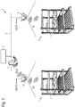
- the RFID communication system 3 is mounted on a flow shelf 7 in the embodiment shown.
- the flow rack 7 here comprises in known manner a plurality of juxtaposed and superimposed chutes, each forming a storage section of the flow rack 7 and are each equipped with an RFID communication system 3 to capture the inventory per storage line / slide can.
- the slide 8 is formed in the illustrated flow shelf 7 in the form of a runway.
- the RFID communication system 3 comprises two electronic control devices 9, each accommodated in its own housing, one of which is arranged in an input region 10 of the flow shelf 7 and the other in an output region 11 of the flow shelf 7.
- In the housing of the respective control device 9 are further each an RFID antenna (not shown) and an optical presence sensor (also not shown).
- the control devices 9, the corresponding RFID antennas and the respective presence sensors are each electrically powered by a battery (not shown).
- an RFID transponder 13 for storing at least one identifier of the corresponding container 12 is mounted in each case.
- the respective control device 9 is able to read out the identifier stored in the RFID transponder 13 in a manner known per se and thus to detect the object 12 or its contents.
- the RFID transponder 13 has a property that represents a strong optical contrast to the container 12, so that the optical presence sensor a contrast change (for example, light-dark) in Vorbeirisonen the container 12 to the RFID antenna of the respective control device 9 can recognize. Only in this case, the control device 9 controls the corresponding RFID antennas to detect the identifier of the RFID transponder.
- the two control devices 9 are configured in the embodiment shown of the RFID communication system 3 to communicate wirelessly, so that for example arranged in the output area 11 control device 9 both information about the goods issue from the storage section 8 in the issuing area 11 as well the control devices 9 arranged in the input area 10 receive information about the goods entered into the storage section 8 in the input area 10 can.
- arranged in the output area 11 control device 9 can determine the current, stored on the storage section 8 inventory and transmit it to the parent logistics system 2 wirelessly.
- each control device 9 in addition to the RFID communication module at least another (low-power) wireless communication module, for example, a BLE communication module , on.
- the same (low-power) wireless communication module as in the example shown here can be used.
- the two control devices 9 in the RFID communication system 3 shown are mounted on a common carrier rail 14, which is a conventional separating rail usually present between the individual adjacent chutes 8.
- the RFID communication system according to the invention described above for the electronic inventory monitoring of a continuous storage, for example, a flow shelf, is not limited to the embodiment disclosed herein, but also includes the same acting other embodiments.
- the RFID communication system according to the invention is used for electronic inventory monitoring on a continuous storage, in particular a flow shelf.
Abstract
Die Erfindung betrifft ein RFID-Kommunikationssystem zur elektronischen Bestandsüberwachung eines Durchlauflagers (7), beispielsweise eines Durchlaufregals, aufweisend wenigstens eine erste und eine zweite RFID-Antenne zum drahtlosen Senden und Empfangen von Daten und einen an einem entlang einer Lagerstrecke (8) des Durchlauflagers (7) bewegbaren Gegenstand (12), beispielsweise einem Behälter, angebrachten RFID-Transponder (13), der mindestens eine Kennung des Gegenstands (12) elektronisch speichert, wobei die erste RFID-Antenne an einem Eingabebereich (10) und die zweite RFID-Antenne an einem Ausgabebereich (11) der Lagerstrecke (8) ortsfest angebracht sind, um den Gegenstand (12) anhand der Kennung des RFID-Transponders (13) zu erfassen. Erfindungsgemäß ist jede RFID-Antenne zu deren Ansteuerung jeweils mit einer ortsfest an der Lagerstrecke (8) angeordneten elektronischen Steuereinrichtung (9) elektrisch verbunden, wobei die Steuereinrichtungen (9) jeweils neben einem RFID-Kommunikationsmodul zur drahtlosen Datenübertragung mit dem RFID-Transponder (13) wenigstens ein weiteres Drahtloskommunikationsmodul zur drahtlosen Datenübertragung mit wenigstens einem weiteren Kommunikationspartner (2, 9) aufweisen.The invention relates to an RFID communication system for the electronic inventory monitoring of a continuous storage (7), for example, a flow shelf, comprising at least a first and a second RFID antenna for wireless transmission and reception of data and one at along a storage path (8) of the continuous storage ( 7) movable object (12), for example a container, mounted RFID transponder (13) electronically stores at least one identifier of the article (12), wherein the first RFID antenna at an input area (10) and the second RFID antenna are stationarily mounted on an output area (11) of the storage section (8) in order to detect the object (12) on the basis of the identifier of the RFID transponder (13). In accordance with the invention, each RFID antenna is electrically connected to an electronic control device (9) which is stationarily mounted on the storage section (8), the control devices (9) each being next to an RFID communication module for wireless data transmission with the RFID transponder (13 ) comprise at least one further wireless communication module for wireless data transmission with at least one further communication partner (2, 9).
Description
Die vorliegende Erfindung betrifft ein RFID-Kommunikationssystem (Radiofrequenz-Identifikations-Kommunikationssystem) zur elektronischen Bestandsüberwachung eines Durchlauflagers, beispielsweise eines Durchlaufregals, nach dem Oberbegriff des Anspruchs 1.The present invention relates to an RFID communication system (radio frequency identification communication system) for electronic inventory monitoring of a continuous storage, for example, a flow shelf, according to the preamble of
Derartige Durchlauflager, zum Beispiel Durchlaufregale oder auch Schrägregale, sind in der Industrie für die Lagerung und Bereitstellung diverser Materialien sehr weit verbreitet, zum Beispiel in der Produktion oder Montage, der Automobilindustrie und in Industriebetrieben mit Serienfertigungen.Such flow storage, for example flow shelves or inclined shelves, are very common in the industry for the storage and supply of various materials, for example in production or assembly, the automotive industry and in industrial plants with mass production.
Durchlauflager sind Lagereinrichtungen, die zum Beispiel mittels geführter Rollwagen auf Durchlaufbahnen oder mittels Behältern oder Paletten auf Rollbahnen mit Waren bestückt werden.Continuous storage facilities are storage facilities that are stocked for example by means of guided trolleys on continuous trays or by means of containers or pallets on taxiways with goods.
Durchlaufregale haben den Vorteil, dass sie für verschiedene Materialbehälter angepasst werden können (Breite der "Rutschen") und hinsichtlich der Anzahl der Rutschen und der Anzahl der Behälter pro Rutsche unterschiedlich dimensioniert werden können (Tiefe der Rutschen pro Regal). Da die Behälter in den Durchlaufregalen gewöhnlich auf Rollen gelagert sind, können bei Entnahme eines Behälters an der Ausgabeseite des Regals die dahinterstehenden Behälter mit dem entsprechenden Material automatisch nachrücken. Dadurch kann eine einfache Entnahme durch den Fertigungsmitarbeiter vorne am Regal (Ausgabebereich) erfolgen, während eine einfache Beladung bzw. Nachschubsteuerung auf der Rückseite des Regals (Eingabebereich) erfolgen kann.Flow-through shelves have the advantage that they can be adapted to different material containers (width of the "slides") and can be dimensioned differently with regard to the number of chutes and the number of containers per chute (depth of chutes per shelf). Since the containers are usually stored in the flow racks on rollers, when removing a container on the output side of the shelf, the underlying container with the appropriate material can move automatically. This allows easy removal by the shop floor operator at the front of the rack (dispensing area), while easy loading or replenishment control can be done on the back of the shelf (input area).
RFID-Kommunikationssysteme für die Lager- und/oder Produktionslogistik umfassen in der Regel ein RFID-Gerät zum Auslesen und/oder Beschreiben eines RFID-Transponders, der an den Gegenständen, Produkten, Behältern bzw. Paletten angebracht ist. An das RFID-Gerät ist dafür eine Antenne elektrisch angeschlossen, die entweder fest in das RFID-Gerät integriert ist oder als externe Antenne genutzt wird. Zur Kommunikation mit dem Transponder erzeugt die Antenne des RFID-Geräts ein elektromagnetisches Feld im Radiofrequenzbereich, das in einer Antenne des Transponders eine Spannung induziert. Damit können einerseits Daten zwischen dem RFID-Gerät und dem RFID-Transponder übertragen werden, andererseits wird dadurch der Transponder mit Energie versorgt.RFID communication systems for warehousing and / or production logistics typically include an RFID device for reading and / or writing an RFID transponder, which is attached to the objects, products, containers or pallets. To the RFID device for an antenna is electrically connected, which is either permanently integrated into the RFID device or as external Antenna is used. For communication with the transponder, the antenna of the RFID device generates an electromagnetic field in the radio frequency range, which induces a voltage in an antenna of the transponder. This data on the one hand between the RFID device and the RFID transponder can be transmitted, on the other hand, thereby the transponder is supplied with energy.
Gegenwärtige Lagerungssysteme nutzen RFID-Kommunikation, um an der Ausgabeseite von Durchlauflagern die Entnahme von Waren zu registrieren und damit den Warenbestand zu erfassen und zu kontrollieren. Hierzu werden die mit einem RFID-Transponder versehenen Waren beim Verlassen des Durchlauflagers an einem stationären RFID-Gerät mit Antenne vorbeigeführt, um die im Transponder gespeicherte Kennung auszulesen. Auf diese Weise wird der Warenausgang automatisch erfasst und in einem Logistiksystem entsprechend verbucht.Current storage systems use RFID communication to register the removal of goods at the exit side of transit warehouses, thereby capturing and controlling inventory. For this purpose, the goods provided with an RFID transponder are passed on leaving the transit warehouse at a stationary RFID device with antenna in order to read out the identifier stored in the transponder. In this way, the goods issue is automatically recorded and booked accordingly in a logistics system.
Außerdem ist es bekannt, die RFID-Kommunikation auch auf der Eingabeseite des Durchlauflagers zu nutzen und die Eingabe von Waren in das Durchlauflager zu registrieren, indem die mit RFID-Transpondern versehenen Waren beim Eingeben in das Durchlauflager an einem stationären RFID-Gerät mit Antenne vorbeigeführt werden, um ebenfalls die in dem Transponder gespeicherte Kennung auszulesen. Auf diese Weise wird auch der Wareneingang automatisch erfasst und in einem Logistiksystem entsprechend verbucht, so dass durch das Logistiksystem der aktuelle Bestand an Waren im entsprechenden Durchlauflager bestimmt werden kann. Ein derartiges Durchlauflager ist beispielsweise in der
Nachteilig bei derartigen RFID-Kommunikationssystemen ist allerdings deren relativ aufwändige Montage an Durchlauflagern, zum Beispiel aufgrund einer erforderlichen Verkabelung für die Stromversorgung, sowie deren ungenügende Anpassungsfähigkeit an Durchlauflagern unterschiedlicher Dimensionen (Tiefe und/oder Breite der Rutschen), zum Beispiel für eine nachträgliche Montage des RFID-Kommunikationssystems an einem bestehenden Durchlauflager (Retrofit). So schränkt eine Verkabelung zum Beispiel die Flexibilität des Einsatzorts des Durchlauflagers erheblich ein, denn wenn das Durchlauflager, beispielsweise ein Durchlaufregal, verschoben werden soll, ist eine Neuverlegung der Kabel in jedem Fall erforderlich. Auch eine zum Beispiel während des Betriebs erforderliche Änderung der Konfiguration des Durchlauflagers, beispielsweise der Tiefe und/oder Breite der Rutschen, ist bei einer vorhandenen Verkabelung nur mit erhöhtem Aufwand durchführbar.A disadvantage of such RFID communication systems, however, is their relatively complex assembly of continuous storage, for example due to a required wiring for the power supply, and their insufficient adaptability to continuous storage of different dimensions (depth and / or width of the slides), for example, for a subsequent installation of RFID communication system at an existing transit warehouse (retrofit). For example, cabling severely restricts the flexibility of the location of use of the feed-through bearing, because when the flow storage, such as a Flow shelf, is to be moved, a re-laying of the cable is required in any case. Also, for example, required during operation change the configuration of the continuous storage, for example, the depth and / or width of the slides is feasible with existing wiring only with increased effort.
Vor diesem Hintergrund liegt der vorliegenden Erfindung die Aufgabe zugrunde, ein RFID-Kommunikationssystem zur elektronischen Bestandsüberwachung eines Durchlauflagers, zum Beispiel eines Durchlaufregals, mit einer gegenüber dem aufgezeigten Stand der Technik vereinfachten Montage- und Einsatzfähigkeit bereitzustellen. So soll das RFID-Kommunikationssystem außerdem einfach zu implementieren und für den Betrieb einfach zu initialisieren/konfigurieren sein. Insbesondere sollen auch bestehende Durchlauflager, zum Beispiel Durchlaufregale, ohne großen Aufwand mit dem RFID-Kommunikationssystem nachrüstbar sein, wobei eine Anpassung an unterschiedliche Standorte des Durchlauflagers, der Tiefen und/oder Breiten der Rutschen flexibel möglich sein soll, sogar während des Betriebs, zum Beispiel wenn die Produktion umgebaut wird, das heißt das Durchlaufregal verschoben wird oder die Konfiguration der Regalplätze geändert wird und dergleichen.Against this background, the present invention has the object to provide an RFID communication system for electronic inventory monitoring of a continuous storage, for example, a flow rack, with a comparison with the prior art simplified assembly and operational capability. In addition, the RFID communication system should be easy to implement and easy to initialize / configure for operation. In particular, existing continuous storage, for example, flow shelves, without much effort with the RFID communication system to be retrofitted, with an adaptation to different locations of the continuous storage, the depths and / or widths of the slides should be flexible, even during operation, for example when the production is rebuilt, that is, the flow shelf is shifted or the configuration of the shelf space is changed and the like.
Diese Aufgabe wird durch ein RFID-Kommunikationssystem mit den Merkmalen des Anspruchs 1 gelöst. Weitere, besonders vorteilhafte Ausgestaltungen der Erfindung offenbaren die Unteransprüche.This object is achieved by an RFID communication system with the features of
Es ist darauf hinzuweisen, dass die in der nachfolgenden Beschreibung einzeln aufgeführten Merkmale in beliebiger, technisch sinnvoller Weise miteinander kombiniert werden können und weitere Ausgestaltungen der Erfindung aufzeigen. Die Beschreibung charakterisiert und spezifiziert die Erfindung insbesondere im Zusammenhang mit den Figuren zusätzlich.It should be noted that the features listed individually in the following description can be combined with one another in any technically meaningful manner and show further embodiments of the invention. The description additionally characterizes and specifies the invention, in particular in connection with the figures.
Erfindungsgemäß weist ein RFID-Kommunikationssystem zur elektronischen Bestandsüberwachung eines Durchlauflagers, beispielsweise eines Durchlaufregals, wenigstens eine erste und eine zweite RFID-Antenne zum drahtlosen Senden und Empfangen von Daten und einen an einem entlang einer Lagerstrecke des Durchlauflagers bewegbaren Gegenstand, beispielsweise einem Behälter, angebrachten RFID-Transponder auf, der mindestens eine Kennung des Gegenstands elektronisch speichert, wobei die erste RFID-Antenne an einem Eingabebereich und die zweite RFID-Antenne an einem Ausgabebereich der Lagerstrecke ortsfest angebracht sind, um den Gegenstand anhand der Kennung des RFID-Transponders zu erfassen. Hierunter ist eine Identifizierung des Gegenstands, zum Beispiel des Behälters, einschließlich dessen Inhalts (Menge und Art der Waren) zu verstehen. Gemäß der Erfindung ist jede RFID-Antenne zu deren Ansteuerung jeweils mit einer ortsfest an der Lagerstrecke angeordneten elektronischen Steuereinrichtung elektrisch verbunden, wobei die Steuereinrichtungen jeweils neben einem RFID-Kommunikationsmodul zur drahtlosen Datenübertragung mit dem RFID-Transponder wenigstens ein weiteres Drahtloskommunikationsmodul zur drahtlosen Datenübertragung mit wenigstens einem weiteren Kommunikationspartner aufweisen. Auf diese Weise kann auf eine Verkabelung der Steuereinrichtungen mit dem weiteren Kommunikationspartner verzichtet werden, was eine erhebliche Vereinfachung der Montage des RFID-Kommunikationsmoduls am Durchlauflager bedeutet. Selbst bei Durchlauflagern, insbesondere Durchlaufregalen, mit unterschiedlichen Tiefen und/oder Breiten der einzelnen Lagerstrecken bzw. Rutschen, ist eine (auch nachträgliche) Montage des RFID-Kommunikationsmoduls einfach und ohne großen Aufwand möglich. Auch eine Änderung des Standorts des Durchlauflagers oder dessen Konfiguration (Tiefe/Breite der Rutschen) ist während des Betriebs ohne großen Aufwand möglich, da sich das erfindungsgemäße RFID-Kommunikationssystem flexibel hieran anpassen lässt.According to the invention, an RFID communication system for electronic inventory monitoring of a continuous storage, for example, a flow rack, at least a first and a second RFID antenna for wireless transmission and reception of data and a movable along a storage path of the continuous storage object, for example a A container, mounted RFID transponder, which electronically stores at least one identifier of the item, the first RFID antenna being fixedly mounted on an input area and the second RFID antenna being fixedly mounted on an output area of the storage area in order to place the item on the basis of the identifier of the RFID tag. Capture transponders. This is an identification of the object, for example the container, including its contents (quantity and type of goods) to understand. According to the invention, each RFID antenna is electrically connected to their control in each case with a fixedly arranged on the storage section electronic control device, the control means each next to an RFID communication module for wireless data transmission with the RFID transponder at least one further wireless communication module for wireless data transmission with at least have another communication partner. In this way, can be dispensed with a wiring of the control devices with the other communication partner, which means a considerable simplification of the assembly of the RFID communication module at the flow storage. Even with continuous storage, especially through racks, with different depths and / or widths of the individual storage sections or slides, a (even subsequent) installation of the RFID communication module is possible easily and without much effort. A change in the location of the continuous storage or its configuration (depth / width of the slides) is possible during operation without much effort, since the RFID communication system according to the invention can be flexibly adapted to this.
Die Erfassung der in dem RFID-Transponder gespeicherten Kennung kann in an sich bekannter Weise mit 13,56 MHz oder 868 MHz erfolgen.The detection of the identifier stored in the RFID transponder can be carried out in a manner known per se with 13.56 MHz or 868 MHz.
Der wenigstens eine weitere Kommunikationspartner der Steuereinrichtungen kann ein übergeordnetes Logistiksystem sein, zum Beispiel ein Produktions- oder Lagerlogistiksystem, ERP (Enterprise Resource Planning), MES (Manufacturing Execution System) und dergleichen, an das die von den RFID-Antennen bzw. den Steuereinrichtungen erfassten Kennungen der RFID-Transponder der Gegenstände, zum Beispiel Behälter oder Paletten, im Eingabe- und Ausgabebereich des Durchlauflagers drahtlos übermittelt werden. Auf diese Weise ist eine genaue Bestandserfassung der in dem Durchlauflager bzw. auf der mit dem RFID-Kommunikationssystem erfassten Lagerstrecke/Rutsche gelagerten Gegenstände bzw. Waren jederzeit möglich.The at least one other communication partner of the control devices may be a higher-level logistics system, for example a production or warehouse logistics system, ERP (Enterprise Resource Planning), MES (Manufacturing Execution System) and the like, to which the RFID antennas or the control devices detected Identifiers of the RFID transponders of the objects, for example containers or pallets, are transmitted wirelessly in the input and output area of the transit warehouse. In this way, a precise inventory of the in the transit camp or on the items or goods stored with the RFID communication system covered storage area / slide at any time.
Der wenigstens eine weitere Kommunikationspartner kann gemäß einer weiteren vorteilhaften Ausgestaltung der Erfindung auch die derselben Lagerstrecke des Durchlauflagers zugeordnete weitere Steuereinrichtung sein. So können beispielsweise die dem Eingabebereich und dem Ausgabebereich zugeordneten Steuereinrichtungen die jeweiligen Kennungen der erfassten Gegenstände drahtlos miteinander austauschen, so dass wenigstens eine dieser Steuereinrichtungen den genauen Bestand der auf der Lagerstrecke gelagerten Gegenstände bzw. Waren erfassen kann. Auf diese Weise kann der Warenbestand der entsprechenden Lagerstrecke bereits direkt am Durchlauflager erfasst werden, der anschließend gegebenenfalls an ein übergeordnetes Logistiksystem drahtlos weitergeleitet werden kann.The at least one further communication partner may be according to a further advantageous embodiment of the invention, the same storage section of the continuous storage associated further control device. For example, the control devices associated with the input area and the output area can wirelessly exchange the respective identifiers of the detected objects so that at least one of these control devices can detect the exact inventory of the articles or goods stored on the storage path. In this way, the inventory of the corresponding storage line can already be detected directly at the transit warehouse, which can then optionally be forwarded to a higher-level logistics system wirelessly.
Die drahtlose Kommunikation zwischen der Steuereinrichtung und dem übergeordneten Logistiksystem und/oder mit der anderen Steuereinrichtung kann vorzugsweise über eine Low-Power-Funktechnologie, beispielsweise Bluetooth-Low-Energy (BLE), erfolgen. Dementsprechend kann das Drahtloskommunikationsmodul ein Low-Power-Drahtloskommunikationsmodul wie beispielsweise ein BLE-Kommunikationsmodul sein. Auf diese Weise kann der Stromverbrauch des RFID-Kommunikationssystems reduziert werden.The wireless communication between the control device and the superordinate logistics system and / or with the other control device can preferably take place via a low-power radio technology, for example Bluetooth low-energy (BLE). Accordingly, the wireless communication module may be a low-power wireless communication module, such as a BLE communication module. In this way, the power consumption of the RFID communication system can be reduced.
Eine noch weitere vorteilhafte Ausgestaltung der Erfindung sieht vor, dass wenigstens ein Präsenzsensor zur Erfassung der Präsenz des Gegenstands, beispielsweise eines Behälters oder einer Palette, im Ein- und/oder Ausgabebereich der Lagerstrecke vorgesehen ist, wobei der wenigstens eine Präsenzsensor mit der wenigstens einen Steuereinrichtung elektronisch verbunden ist. Hierbei können beispielsweise ein erster Präsenzsensor im Eingabebereich und ein zweiter Präsenzsensor im Ausgabebereich der Lagerstrecke des Durchlauflagers ortsfest angeordnet und der jeweiligen RFID-Antenne zugeordnet sein. Besonders bevorzugt ist hierbei die mit dem jeweiligen Präsenzsensor verbundene Steuereinrichtung dazu eingerichtet, ein Lesen des RFID-Transponders mittels der entsprechenden RFID-Antenne erst dann zu aktivieren, wenn die Präsenz des Gegenstands von dem jeweiligen Präsenzsensor erfasst ist. So lassen sich der Stromverbrauch und damit die Betriebskosten des RFID-Kommunikationssystems auf ein Minimum reduzieren.A still further advantageous embodiment of the invention provides that at least one presence sensor for detecting the presence of the object, for example a container or a pallet, is provided in the input and / or output area of the storage section, wherein the at least one presence sensor with the at least one control device electronically connected. Here, for example, a first presence sensor in the input area and a second presence sensor in the output area of the storage section of the continuous storage station can be arranged stationary and associated with the respective RFID antenna. In this case, the control device connected to the respective presence sensor is particularly preferably configured to activate reading of the RFID transponder by means of the corresponding RFID antenna only when the presence of the object from the respective presence sensor is detected. This reduces the power consumption and thus the operating costs of the RFID communication system to a minimum.
Der Präsenzsensor kann beispielsweise ein optischer Sensor sein, wobei dann der RFID-Transponder bevorzugt einen im Vergleich zur Oberfläche des Gegenstands, auf der er angebracht ist, hohen optischen Kontrast aufweist, der von dem Präsenzsensor erfassbar ist.The presence sensor may, for example, be an optical sensor, in which case the RFID transponder preferably has a high optical contrast, which is detectable by the presence sensor, in comparison with the surface of the object on which it is mounted.
Gemäß einer noch weiteren vorteilhaften Ausgestaltung der Erfindung ist zur elektrischen Speisung der Steuereinrichtung wenigstens eine Batterie vorgesehen. Somit lässt sich das ganze erfindungsgemäße RFID-Kommunikationssystem vollkommen autark am Durchlauflager betreiben. Somit kann auch der Standort des Durchlauflagers unabhängig von einer externen Stromversorgung gewählt und/oder sogar während des Betriebs des RFID-Kommunikationssystems geändert werden.According to yet another advantageous embodiment of the invention, at least one battery is provided for the electrical supply of the control device. Thus, the whole RFID communication system according to the invention can operate completely self-sufficient on the continuous storage. Thus, the location of the transit warehouse can be selected independently of an external power supply and / or even changed during operation of the RFID communication system.
Eine noch weitere vorteilhafte Ausgestaltung der Erfindung sieht vor, dass die Steuereinrichtung und die mit dieser elektronisch verbundenen Komponenten, beispielsweise RFID-Antenne(n) und/oder Präsenzsensor(en) und/oder Batterie(n), in einem gemeinsamen Gehäuse aufgenommen sind. Da die Steuereinrichtung demgemäß eine Einheit mit den mit dieser elektronisch verbundenen Komponenten bildet, lässt sich die Montage des RFID-Kommunikationssystems am Durchlauflager weiter vereinfachen.A still further advantageous embodiment of the invention provides that the control device and the components electronically connected thereto, for example RFID antenna (s) and / or presence sensor (s) and / or battery (s), are accommodated in a common housing. Since the control device accordingly forms a unit with the components connected to it electronically, the assembly of the RFID communication system at the feed-through bearing can be further simplified.
Eine noch einfacherer Montage des RFID-Kommunikationssystems kann erreicht werden, wenn die Steuereinrichtungen und die mit diesen elektronisch verbundenen Komponenten, beispielsweise RFID-Antenne(n) und/oder Präsenzsensor(en), auf einer entlang der Lagerstrecke befestigbaren, gemeinsamen Trägerschiene, beispielsweise einer die Rutschen eines Durchlaufregals voneinander separierenden Trennschiene, angeordnet sind.An even simpler installation of the RFID communication system can be achieved if the control devices and the components electronically connected thereto, for example RFID antenna (s) and / or presence sensor (s), can be fastened to a common carrier rail, for example a the slides of a continuous shelf separate separating rail, are arranged.
Weitere Merkmale und Vorteile der Erfindung ergeben sich aus der folgenden Beschreibung eines nicht einschränkend zu verstehenden Ausführungsbeispiels der Erfindung, die im Folgenden unter Bezugnahme auf die Zeichnung näher erläutert wird. In dieser Zeichnung zeigen schematisch:
- Fig. 1
- eine Systemübersicht eines Logistiksystems mit einem RFID-Kommunikationssystem gemäß der Erfindung und
- Fig. 2
- das RFID-Kommunikationssystem aus
Fig. 1 an einer Lagerstrecke eines Durchlaufregals.
- Fig. 1
- a system overview of a logistics system with an RFID communication system according to the invention and
- Fig. 2
- the RFID communication system
Fig. 1 on a storage section of a flow shelf.
In den unterschiedlichen Figuren sind hinsichtlich ihrer Funktion gleichwertige Teile stets mit denselben Bezugszeichen versehen, so dass diese in der Regel auch nur einmal beschrieben werden.In the different figures, equivalent parts are always provided with the same reference numerals with respect to their function, so that these are usually described only once.
Wie in
Auf den auf der Rutsche 8 bzw. entlang der Lagerstrecke 8 bewegbaren Gegenständen 12, die hier in Form von Behältern 12 ausgebildet sind, ist jeweils ein RFID-Transponder 13 zur Speicherung wenigstens einer Kennung des entsprechenden Behälters 12 angebracht. Mittels der RFID-Antenne ist die jeweilige Steuereinrichtung 9 in der Lage, die in dem RFID-Transponder 13 gespeicherte Kennung in an sich bekannter Weise auszulesen und somit den Gegenstand 12 bzw. dessen Inhalt zu erfassen. Um den Energiebedarf des RFID-Kommunikationssystems 3 so gering wie möglich zu halten, weist der RFID-Transponder 13 eine Eigenschaft auf, die einen starken optischen Kontrast zum Behälter 12 darstellt, so dass der optische Präsenzsensor einen Kontrastwechsel (zum Beispiel hell-dunkel) beim Vorbeirutschen des Behälters 12 an der RFID-Antenne der jeweiligen Steuereinrichtung 9 erkennen kann. Erst in diesem Fall steuert die Steuereinrichtung 9 die entsprechenden RFID-Antennen an, um die Kennung des RFID-Transponders zu erfassen.On the
Des Weiteren sind die beiden Steuereinrichtungen 9 bei dem gezeigten Ausführungsbeispiel des RFID-Kommunikationssystems 3 dazu eingerichtet, miteinander drahtlos zu kommunizieren, so dass zum Beispiel die im Ausgabebereich 11 angeordnete Steuereinrichtung 9 sowohl Informationen über den Warenausgang von der Lagerstrecke 8 im Ausgebebereich 11 als auch über die im Eingabebereich 10 angeordnete Steuereinrichtungen 9 Informationen über die in die Lagerstrecke 8 im Eingabebereich 10 eingegebenen Waren erhalten kann. Auf diese Weise kann zum Beispiel die im Ausgabebereich 11 angeordnete Steuereinrichtung 9 den aktuellen, auf der Lagerstrecke 8 gelagerten Warenbestand ermitteln und an das übergeordnete Logistiksystem 2 drahtlos übermitteln. Zur drahtlosen Kommunikation der Steuereinrichtungen 9 untereinander und/oder zur drahtlosen Kommunikation der Steuereinrichtung(en) 9 mit dem Logistiksystem 2 weist jede Steuereinrichtung 9 neben dem RFID-Kommunikationsmodul wenigstens noch ein weiteres (Low-Power-) Drahtloskommunikationsmodul, zum Beispiel ein BLE-Kommunikationsmodul, auf. Zur drahtlosen Kommunikation der Steuereinrichtungen 9 untereinander und mit dem übergeordneten Logistiksystem 2 kann dasselbe (Low-Power-) Drahtloskommunikationsmodul wie in dem hier dargestellten Beispiel verwendet werden.Furthermore, the two
Wie
Das vorstehend beschriebene erfindungsgemäße RFID-Kommunikationssystem zur elektronischen Bestandsüberwachung eines Durchlauflagers, beispielsweise eines Durchlaufregals, ist nicht auf die hierin offenbarte Ausführungsform beschränkt, sondern umfasst auch gleich wirkende weitere Ausführungsformen.The RFID communication system according to the invention described above for the electronic inventory monitoring of a continuous storage, for example, a flow shelf, is not limited to the embodiment disclosed herein, but also includes the same acting other embodiments.
In bevorzugter Ausführung wird das erfindungsgemäße RFID-Kommunikationssystem zur elektronischen Bestandsüberwachung an einem Durchlauflager, insbesondere einem Durchlaufregal, verwendet.In a preferred embodiment, the RFID communication system according to the invention is used for electronic inventory monitoring on a continuous storage, in particular a flow shelf.
- 11
- SystemübersichtSystem Overview
- 22
- Logistiksystemlogistics system
- 33
- RFID-KommunikationssystemRFID communication system
- 44
- Ethernet- oder WLAN-NetzwerkEthernet or Wi-Fi network
- 55
- WLAN-FunkstationWLAN radio station
- 66
- Ethernet-/WLAN-BLE-KonverterEthernet / wireless BLE converter
- 77
- DurchlaufregalFlow rack
- 88th
- Lagerstrecke, RutscheWarehouse track, slide
- 99
- Elektronische SteuereinrichtungElectronic control device
- 1010
- Eingabebereichinput Panel
- 1111
- Ausgabebereichoutput area
- 1212
- Gegenstand, BehälterObject, container
- 1313
- RFID-TransponderRFID transponder
- 1414
- Trägerschienesupport rail
Claims (10)
dadurch gekennzeichnet, dass
jede RFID-Antenne zu deren Ansteuerung jeweils mit einer ortsfest an der Lagerstrecke (8) angeordneten elektronischen Steuereinrichtung (9) elektrisch verbunden ist, wobei die Steuereinrichtungen (9) jeweils neben einem RFID-Kommunikationsmodul zur drahtlosen Datenübertragung mit dem RFID-Transponder (13) wenigstens ein weiteres Drahtloskommunikationsmodul zur drahtlosen Datenübertragung mit wenigstens einem weiteren Kommunikationspartner (2, 9) aufweisen.RFID communication system for the electronic inventory monitoring of a continuous storage (7), for example, a flow rack, comprising at least a first and a second RFID antenna for wireless transmission and reception of data and on a along a storage path (8) of the continuous storage (7) movable object (12), for example a container, mounted RFID transponder (13) electronically stores at least one identifier of the article (12), wherein the first RFID antenna at an input area (10) and the second RFID antenna at an output area ( 11) of the bearing section (8) are fixedly mounted in order to detect the object (12) on the basis of the identifier of the RFID transponder (13),
characterized in that
Each RFID antenna for controlling thereof is electrically connected to an electronic control device (9) arranged stationarily on the storage section (8), wherein the control devices (9) are each next to an RFID communication module for wireless data transmission with the RFID transponder (13). at least one further wireless communication module for wireless data transmission with at least one further communication partner (2, 9).
dadurch gekennzeichnet, dass
der weitere Kommunikationspartner ein übergeordnetes Logistiksystem (2) ist.RFID communication system according to claim 1,
characterized in that
the other communication partner is a higher-level logistics system (2).
dadurch gekennzeichnet, dass
der weitere Kommunikationspartner die derselben Lagerstrecke (8) zugeordnete weitere Steuereinrichtung (9) ist.RFID communication system according to claim 1 or 2,
characterized in that
the other communication partner is the other storage device (8) associated with further control device (9).
dadurch gekennzeichnet, dass
wenigstens eine Steuereinrichtung (9) derselben Lagerstrecke (8) dazu eingerichtet ist, den aktuell in der Lagerstrecke (8) gelagerten Bestand an Gegenständen (12) zu erfassen.RFID communication system according to the preceding claim,
characterized in that
at least one control device (9) of the same storage section (8) is adapted to detect the stock of objects (12) currently stored in the storage section (8).
dadurch gekennzeichnet, dass
wenigstens ein Präsenzsensor zur Erfassung der Präsenz des Gegenstands (12) im Ein- (10) und/oder Ausgabebereich (11) der Lagerstrecke (8) vorgesehen ist, wobei der wenigstens eine Präsenzsensor mit der wenigstens einen Steuereinrichtung (9) elektronisch verbunden ist.RFID communication system according to one of the preceding claims,
characterized in that
at least one presence sensor for detecting the presence of the object (12) in the input (10) and / or output area (11) of the storage section (8) is provided, wherein the at least one presence sensor with the at least one control device (9) is electronically connected.
dadurch gekennzeichnet, dass
ein erster Präsenzsensor im Eingabebereich (10) und ein zweiter Präsenzsensor im Ausgabebereich (11) ortsfest angeordnet und der jeweiligen RFID-Antenne zugeordnet sind, wobei die mit dem jeweiligen Präsenzsensor verbundene Steuereinrichtung (9) dazu eingerichtet ist, ein Lesen des RFID-Transponders (13) mittels der entsprechenden RFID-Antenne erst dann zu aktivieren, wenn die Präsenz des Gegenstands (12) von dem jeweiligen Präsenzsensor erfasst ist.RFID communication system according to the preceding claim,
characterized in that
a first presence sensor in the input area (10) and a second presence sensor in the output area (11) are arranged stationary and assigned to the respective RFID antenna, wherein the control device (9) connected to the respective presence sensor is adapted to read the RFID transponder ( 13) by means of the corresponding RFID antenna only to be activated when the presence of the object (12) is detected by the respective presence sensor.
dadurch gekennzeichnet, dass
der Präsenzsensor ein optischer Sensor ist und der RFID-Transponder (13) einen im Vergleich zur Oberfläche des Gegenstands, auf der er angebracht ist, hohen optischen Kontrast aufweist, der von dem Präsenzsensor erfassbar ist.RFID communication system according to one of the two preceding claims,
characterized in that
the presence sensor is an optical sensor and the RFID transponder (13) has a high optical contrast detectable by the presence sensor compared to the surface of the object on which it is mounted.
dadurch gekennzeichnet, dass
zur elektrischen Speisung der Steuereinrichtung (9) wenigstens eine Batterie vorgesehen ist.RFID communication system according to one of the preceding claims,
characterized in that
for electrical supply of the control device (9) at least one battery is provided.
dadurch gekennzeichnet, dass
die Steuereinrichtung (9) und die mit dieser elektronisch verbundenen Komponenten, beispielsweise RFID-Antenne(n) und/oder Präsenzsensor(en) und/oder Batterie(n), in einem gemeinsamen Gehäuse aufgenommen sind.RFID communication system according to one of the preceding claims,
characterized in that
the control device (9) and the components connected to it electronically, for example RFID antenna (s) and / or presence sensor (s) and / or battery (s), are accommodated in a common housing.
dadurch gekennzeichnet, dass
die Steuereinrichtungen (9) und die mit diesen elektronisch verbundenen Komponenten, beispielsweise RFID-Antenne(n) und/oder Präsenzsensor(en), auf einer entlang der Lagerstrecke (8) befestigbaren, gemeinsamen Trägerschiene (14) angeordnet sind.RFID communication system according to one of the preceding claims,
characterized in that
the control devices (9) and the components connected to them electronically, for example RFID antenna (s) and / or presence sensor (s), are arranged on a common carrier rail (14) which can be fastened along the storage path (8).
Applications Claiming Priority (1)
| Application Number | Priority Date | Filing Date | Title |
|---|---|---|---|
| DE102016008942 | 2016-07-26 |
Publications (1)
| Publication Number | Publication Date |
|---|---|
| EP3276552A1 true EP3276552A1 (en) | 2018-01-31 |
Family
ID=59501188
Family Applications (1)
| Application Number | Title | Priority Date | Filing Date |
|---|---|---|---|
| EP17182779.3A Withdrawn EP3276552A1 (en) | 2016-07-26 | 2017-07-24 | Rfid communication system for electronic stock monitoring of a flow rack |
Country Status (1)
| Country | Link |
|---|---|
| EP (1) | EP3276552A1 (en) |
Cited By (1)
| Publication number | Priority date | Publication date | Assignee | Title |
|---|---|---|---|---|
| DE102022107824A1 (en) | 2022-04-01 | 2023-10-05 | ORGATEX GmbH | Method for controlling and monitoring an intralogistics process |
Citations (3)
| Publication number | Priority date | Publication date | Assignee | Title |
|---|---|---|---|---|
| GB2429559A (en) * | 2005-08-23 | 2007-02-28 | Microlise Ltd | RFID portal arrangements |
| DE202010012667U1 (en) * | 2010-09-16 | 2010-12-02 | Almert, Toni H. | Dynamic storage system |
| DE102010029996A1 (en) | 2010-06-11 | 2011-12-15 | Brooks Automation (Germany) Gmbh | Inventory monitoring of transit warehouses by means of RFID |
-
2017
- 2017-07-24 EP EP17182779.3A patent/EP3276552A1/en not_active Withdrawn
Patent Citations (3)
| Publication number | Priority date | Publication date | Assignee | Title |
|---|---|---|---|---|
| GB2429559A (en) * | 2005-08-23 | 2007-02-28 | Microlise Ltd | RFID portal arrangements |
| DE102010029996A1 (en) | 2010-06-11 | 2011-12-15 | Brooks Automation (Germany) Gmbh | Inventory monitoring of transit warehouses by means of RFID |
| DE202010012667U1 (en) * | 2010-09-16 | 2010-12-02 | Almert, Toni H. | Dynamic storage system |
Cited By (1)
| Publication number | Priority date | Publication date | Assignee | Title |
|---|---|---|---|---|
| DE102022107824A1 (en) | 2022-04-01 | 2023-10-05 | ORGATEX GmbH | Method for controlling and monitoring an intralogistics process |
Similar Documents
| Publication | Publication Date | Title |
|---|---|---|
| EP2937279B1 (en) | Freight loading system for loading and unloading of an item of freight, method for creating and/or updating a loading plan | |
| EP2675709B1 (en) | Cargo loading system and method for controlling a multiple roller conveyor | |
| EP2145298B1 (en) | Method and device for transporting items to distribution points | |
| EP2903086B1 (en) | RFID reading device for shelf occupancy detection | |
| EP1829813B1 (en) | Industrial truck with a display unit for operators | |
| EP3291144B1 (en) | Rfid device and method for detecting compartment occupation | |
| WO2011047864A2 (en) | System and method for storage in an aircraft galley | |
| DE102008057076A1 (en) | Loading system and method for loading a cargo space of an aircraft | |
| DE102011009739A1 (en) | Device and method for detecting the inventory of a sales and / or storage facility as well as a warehouse management system equipped therewith | |
| EP3087877B1 (en) | Checkout system assembly with goods separator detection | |
| EP2580716B1 (en) | Monitoring the stock in dynamic stores using rfid | |
| EP2479719A2 (en) | System and method for storing and monitoring goods using RFID technology | |
| EP2500850B1 (en) | Method and system for monitoring objects | |
| DE102011000819A1 (en) | Cargo loading system for use in aircraft, has touch screen type input unit that is in communicative connection with control computer, to forward input data to control computer | |
| EP3276552A1 (en) | Rfid communication system for electronic stock monitoring of a flow rack | |
| EP3679432A1 (en) | Method and production station for identifying workpieces with a mobile unit | |
| EP2390204B1 (en) | System for completing a warehouse for small articles | |
| EP2012263B1 (en) | Intelligent shelving unit | |
| EP2479720B1 (en) | System and method for storing and monitoring goods using RFID technology | |
| EP2538377A2 (en) | Method for handling Kanban jobs and RFID pallet box | |
| AT519019B1 (en) | Storage system with a storage location associated detection arrangement | |
| EP3825798B1 (en) | Mobile system controller | |
| EP3273382A1 (en) | Rfid reading device and method for compartment occupancy detection in a shelf | |
| EP2763088A1 (en) | Parts store for spare parts | |
| EP2263196B1 (en) | Rfid system |
Legal Events
| Date | Code | Title | Description |
|---|---|---|---|
| PUAI | Public reference made under article 153(3) epc to a published international application that has entered the european phase |
Free format text: ORIGINAL CODE: 0009012 |
|
| AK | Designated contracting states |
Kind code of ref document: A1 Designated state(s): AL AT BE BG CH CY CZ DE DK EE ES FI FR GB GR HR HU IE IS IT LI LT LU LV MC MK MT NL NO PL PT RO RS SE SI SK SM TR |
|
| AX | Request for extension of the european patent |
Extension state: BA ME |
|
| 17P | Request for examination filed |
Effective date: 20180730 |
|
| RBV | Designated contracting states (corrected) |
Designated state(s): AL AT BE BG CH CY CZ DE DK EE ES FI FR GB GR HR HU IE IS IT LI LT LU LV MC MK MT NL NO PL PT RO RS SE SI SK SM TR |
|
| 17Q | First examination report despatched |
Effective date: 20190301 |
|
| STAA | Information on the status of an ep patent application or granted ep patent |
Free format text: STATUS: THE APPLICATION HAS BEEN WITHDRAWN |
|
| 18W | Application withdrawn |
Effective date: 20201118 |