EP3087877B1 - Checkout system assembly with goods separator detection - Google Patents
Checkout system assembly with goods separator detection Download PDFInfo
- Publication number
- EP3087877B1 EP3087877B1 EP15165711.1A EP15165711A EP3087877B1 EP 3087877 B1 EP3087877 B1 EP 3087877B1 EP 15165711 A EP15165711 A EP 15165711A EP 3087877 B1 EP3087877 B1 EP 3087877B1
- Authority
- EP
- European Patent Office
- Prior art keywords
- goods
- belt
- belt section
- sensor
- capturing
- Prior art date
- Legal status (The legal status is an assumption and is not a legal conclusion. Google has not performed a legal analysis and makes no representation as to the accuracy of the status listed.)
- Active
Links
- 238000001514 detection method Methods 0.000 title description 99
- 230000007704 transition Effects 0.000 claims description 25
- 238000000034 method Methods 0.000 claims description 21
- 230000005672 electromagnetic field Effects 0.000 claims description 4
- 230000032258 transport Effects 0.000 description 20
- 238000012856 packing Methods 0.000 description 15
- 230000008569 process Effects 0.000 description 15
- 230000004888 barrier function Effects 0.000 description 11
- 230000003287 optical effect Effects 0.000 description 9
- 230000006870 function Effects 0.000 description 7
- 229910000859 α-Fe Inorganic materials 0.000 description 7
- 238000013461 design Methods 0.000 description 4
- 238000011144 upstream manufacturing Methods 0.000 description 4
- 229910052751 metal Inorganic materials 0.000 description 3
- 239000002184 metal Substances 0.000 description 3
- 241000531116 Blitum bonus-henricus Species 0.000 description 2
- 235000008645 Chenopodium bonus henricus Nutrition 0.000 description 2
- 230000008859 change Effects 0.000 description 2
- 239000004033 plastic Substances 0.000 description 2
- 229920003023 plastic Polymers 0.000 description 2
- 238000000926 separation method Methods 0.000 description 2
- 229920005372 Plexiglas® Polymers 0.000 description 1
- 229910000831 Steel Inorganic materials 0.000 description 1
- 229910052782 aluminium Inorganic materials 0.000 description 1
- XAGFODPZIPBFFR-UHFFFAOYSA-N aluminium Chemical compound [Al] XAGFODPZIPBFFR-UHFFFAOYSA-N 0.000 description 1
- 238000013459 approach Methods 0.000 description 1
- 238000004891 communication Methods 0.000 description 1
- 239000002131 composite material Substances 0.000 description 1
- 230000003247 decreasing effect Effects 0.000 description 1
- 238000000151 deposition Methods 0.000 description 1
- 238000010586 diagram Methods 0.000 description 1
- 238000011156 evaluation Methods 0.000 description 1
- 238000009413 insulation Methods 0.000 description 1
- 239000007788 liquid Substances 0.000 description 1
- 239000003550 marker Substances 0.000 description 1
- 239000007769 metal material Substances 0.000 description 1
- 239000000203 mixture Substances 0.000 description 1
- 238000005192 partition Methods 0.000 description 1
- 230000000149 penetrating effect Effects 0.000 description 1
- 239000002985 plastic film Substances 0.000 description 1
- 229920006255 plastic film Polymers 0.000 description 1
- 239000004417 polycarbonate Substances 0.000 description 1
- 229920000515 polycarbonate Polymers 0.000 description 1
- 239000004926 polymethyl methacrylate Substances 0.000 description 1
- 230000004044 response Effects 0.000 description 1
- 239000010959 steel Substances 0.000 description 1
Images


Classifications
-
- G—PHYSICS
- G07—CHECKING-DEVICES
- G07G—REGISTERING THE RECEIPT OF CASH, VALUABLES, OR TOKENS
- G07G1/00—Cash registers
- G07G1/0036—Checkout procedures
- G07G1/0045—Checkout procedures with a code reader for reading of an identifying code of the article to be registered, e.g. barcode reader or radio-frequency identity [RFID] reader
- G07G1/009—Checkout procedures with a code reader for reading of an identifying code of the article to be registered, e.g. barcode reader or radio-frequency identity [RFID] reader the reader being an RFID reader
-
- A—HUMAN NECESSITIES
- A47—FURNITURE; DOMESTIC ARTICLES OR APPLIANCES; COFFEE MILLS; SPICE MILLS; SUCTION CLEANERS IN GENERAL
- A47F—SPECIAL FURNITURE, FITTINGS, OR ACCESSORIES FOR SHOPS, STOREHOUSES, BARS, RESTAURANTS OR THE LIKE; PAYING COUNTERS
- A47F9/00—Shop, bar, bank or like counters
- A47F9/02—Paying counters
- A47F9/04—Check-out counters, e.g. for self-service stores
- A47F9/046—Arrangement of recording means in or on check-out counters
- A47F9/047—Arrangement of recording means in or on check-out counters for recording self-service articles without cashier or assistant
- A47F9/048—Arrangement of recording means in or on check-out counters for recording self-service articles without cashier or assistant automatically
-
- G—PHYSICS
- G06—COMPUTING; CALCULATING OR COUNTING
- G06K—GRAPHICAL DATA READING; PRESENTATION OF DATA; RECORD CARRIERS; HANDLING RECORD CARRIERS
- G06K19/00—Record carriers for use with machines and with at least a part designed to carry digital markings
- G06K19/06—Record carriers for use with machines and with at least a part designed to carry digital markings characterised by the kind of the digital marking, e.g. shape, nature, code
- G06K19/06009—Record carriers for use with machines and with at least a part designed to carry digital markings characterised by the kind of the digital marking, e.g. shape, nature, code with optically detectable marking
- G06K19/06018—Record carriers for use with machines and with at least a part designed to carry digital markings characterised by the kind of the digital marking, e.g. shape, nature, code with optically detectable marking one-dimensional coding
- G06K19/06028—Record carriers for use with machines and with at least a part designed to carry digital markings characterised by the kind of the digital marking, e.g. shape, nature, code with optically detectable marking one-dimensional coding using bar codes
-
- G—PHYSICS
- G06—COMPUTING; CALCULATING OR COUNTING
- G06K—GRAPHICAL DATA READING; PRESENTATION OF DATA; RECORD CARRIERS; HANDLING RECORD CARRIERS
- G06K19/00—Record carriers for use with machines and with at least a part designed to carry digital markings
- G06K19/06—Record carriers for use with machines and with at least a part designed to carry digital markings characterised by the kind of the digital marking, e.g. shape, nature, code
- G06K19/06009—Record carriers for use with machines and with at least a part designed to carry digital markings characterised by the kind of the digital marking, e.g. shape, nature, code with optically detectable marking
- G06K19/06037—Record carriers for use with machines and with at least a part designed to carry digital markings characterised by the kind of the digital marking, e.g. shape, nature, code with optically detectable marking multi-dimensional coding
-
- G—PHYSICS
- G06—COMPUTING; CALCULATING OR COUNTING
- G06K—GRAPHICAL DATA READING; PRESENTATION OF DATA; RECORD CARRIERS; HANDLING RECORD CARRIERS
- G06K19/00—Record carriers for use with machines and with at least a part designed to carry digital markings
- G06K19/06—Record carriers for use with machines and with at least a part designed to carry digital markings characterised by the kind of the digital marking, e.g. shape, nature, code
- G06K19/067—Record carriers with conductive marks, printed circuits or semiconductor circuit elements, e.g. credit or identity cards also with resonating or responding marks without active components
- G06K19/07—Record carriers with conductive marks, printed circuits or semiconductor circuit elements, e.g. credit or identity cards also with resonating or responding marks without active components with integrated circuit chips
- G06K19/077—Constructional details, e.g. mounting of circuits in the carrier
- G06K19/07749—Constructional details, e.g. mounting of circuits in the carrier the record carrier being capable of non-contact communication, e.g. constructional details of the antenna of a non-contact smart card
- G06K19/07758—Constructional details, e.g. mounting of circuits in the carrier the record carrier being capable of non-contact communication, e.g. constructional details of the antenna of a non-contact smart card arrangements for adhering the record carrier to further objects or living beings, functioning as an identification tag
-
- G—PHYSICS
- G06—COMPUTING; CALCULATING OR COUNTING
- G06K—GRAPHICAL DATA READING; PRESENTATION OF DATA; RECORD CARRIERS; HANDLING RECORD CARRIERS
- G06K7/00—Methods or arrangements for sensing record carriers, e.g. for reading patterns
- G06K7/10—Methods or arrangements for sensing record carriers, e.g. for reading patterns by electromagnetic radiation, e.g. optical sensing; by corpuscular radiation
- G06K7/14—Methods or arrangements for sensing record carriers, e.g. for reading patterns by electromagnetic radiation, e.g. optical sensing; by corpuscular radiation using light without selection of wavelength, e.g. sensing reflected white light
- G06K7/1404—Methods for optical code recognition
- G06K7/1408—Methods for optical code recognition the method being specifically adapted for the type of code
-
- G—PHYSICS
- G07—CHECKING-DEVICES
- G07D—HANDLING OF COINS OR VALUABLE PAPERS, e.g. TESTING, SORTING BY DENOMINATIONS, COUNTING, DISPENSING, CHANGING OR DEPOSITING
- G07D7/00—Testing specially adapted to determine the identity or genuineness of valuable papers or for segregating those which are unacceptable, e.g. banknotes that are alien to a currency
- G07D7/003—Testing specially adapted to determine the identity or genuineness of valuable papers or for segregating those which are unacceptable, e.g. banknotes that are alien to a currency using security elements
- G07D7/0034—Testing specially adapted to determine the identity or genuineness of valuable papers or for segregating those which are unacceptable, e.g. banknotes that are alien to a currency using security elements using watermarks
-
- G—PHYSICS
- G07—CHECKING-DEVICES
- G07G—REGISTERING THE RECEIPT OF CASH, VALUABLES, OR TOKENS
- G07G1/00—Cash registers
- G07G1/0036—Checkout procedures
-
- G—PHYSICS
- G07—CHECKING-DEVICES
- G07G—REGISTERING THE RECEIPT OF CASH, VALUABLES, OR TOKENS
- G07G1/00—Cash registers
- G07G1/0036—Checkout procedures
- G07G1/0045—Checkout procedures with a code reader for reading of an identifying code of the article to be registered, e.g. barcode reader or radio-frequency identity [RFID] reader
-
- A—HUMAN NECESSITIES
- A47—FURNITURE; DOMESTIC ARTICLES OR APPLIANCES; COFFEE MILLS; SPICE MILLS; SUCTION CLEANERS IN GENERAL
- A47F—SPECIAL FURNITURE, FITTINGS, OR ACCESSORIES FOR SHOPS, STOREHOUSES, BARS, RESTAURANTS OR THE LIKE; PAYING COUNTERS
- A47F9/00—Shop, bar, bank or like counters
- A47F9/02—Paying counters
- A47F9/04—Check-out counters, e.g. for self-service stores
- A47F2009/041—Accessories for check-out counters, e.g. dividers
Definitions
- the invention relates to a checkout system arrangement according to the preamble of claim 1 and a method for operating a checkout system arrangement according to the preamble of claim 8.
- Such a cash register system arrangement has a conveyor belt device and a goods detection device.
- the conveyor belt device comprises at least one belt section which can be set in a feed movement for the transport of goods located thereon along a goods feed path, the goods being separable from one another by at least one goods divider along the goods feed path.
- the goods detection device is designed and provided to detect goods which are transported by the conveyor belt device.
- a checkout system arrangement of the aforementioned type is from DE 10 2008 010 642 A1 known.
- a goods divider bar with an elongated body and a machine-readable marking is used to separate goods placed on a goods conveyor belt.
- a scanning device serving as a goods detection device for the optical detection of a machine-readable marking on the goods can thus add up the prices of between a first and a second goods dividing rod on the goods conveyor belt.
- the machine-readable markings both on the goods and on the dividing bars are detected by the scanning device.
- the machine-readable marking can be designed as an optical bar code or as an RFID chip.
- a disadvantage of the known cash register system arrangement is that goods placed close to one another on the conveyor belt may not be affected by the scanning device can be clearly recognized, for example because a first item of goods conceals an optical line of sight between the scanning device and a machine-readable marking in the form of an optical code on a second item of goods.
- One possible consequence is an unreliable goods recognition of the known cash register system arrangement.
- customers of the POS system arrangement are often not used to or experienced in placing goods on the conveyor belt at a sufficient distance from one another, so that reliable detection of all goods by the scanning device is ensured. In order to ensure the greatest possible comfort for the customer, it is therefore desirable to ensure reliable goods recognition, even if a customer places his goods on the conveyor belt at close spacing from one another.
- the object of the present invention is to improve the known cash register system arrangement, in particular to improve the reliability of the goods recognition.
- At least one sensor device and a control device are provided, the at least one sensor device being arranged along the goods feed path at a distance from the goods detection device and comprising a sensor and a detection area.
- the sensor device is designed and provided to detect whether a goods divider is in the detection area or not.
- the control device is designed and provided to control the feed movement of the belt section of the conveyor belt device as a function of the detection of the goods separator in the detection area of the sensor device.
- the sensor device Due to the spaced arrangement of the sensor device (in particular the detection area) from the goods detection device, it is possible, by detecting the goods divider, to feed the goods on one of the goods detection device (along the goods feed path) to monitor spaced-apart place.
- the information as to whether or not the goods divider is in the detection range of the sensor device can be used to improve the efficiency and / or the reliability of the goods recognition of the checkout system arrangement.
- the POS system arrangement can generally be used as a checkout point in the wholesale or retail trade, for example in commodity markets such as hardware stores, supermarkets, etc.
- the goods detection device of the cash register system arrangement can be designed as a portal scanner, e.g. as a 360 ° portal scanner with optical detection of the type and number of goods.
- a portal scanner provides a portal through which goods can be transported. During the transport through the portal, the type and number of goods are automatically recognized. This enables a particularly efficient checkout process.
- the cash register system arrangement can also be used with a detection device operated (manually) by personnel.
- the sensor device is arranged upstream of the goods detection device (along the goods feed path).
- the goods separator is placed on the conveyor belt device by a customer in such a way that it is located along the goods feed path between the goods of the customer and the goods of a preceding or following other customer. This means that the divider can display the end of the goods for one customer and the beginning of the goods for the next customer at the same time.
- the control device can determine how long the at least one belt section of the conveyor belt device has to carry out a feed movement at a certain speed so that all of the goods of one customer cover the distance between the detection area of the sensor device and the goods detection device has traveled.
- the sensor device can also be arranged downstream of the goods detection device (along the goods feed path). For example, it could be determined whether the goods separator is being transported by means of the conveyor belt device as expected or whether, for example, there is a backlog of goods.
- the sensor device can be designed to detect by means of the sensor, by reading out a machine-readable code provided on the goods divider, whether the goods divider is in the detection area. This makes it possible to detect a divider particularly clearly.
- the machine-readable code can in particular be read out with the aid of electromagnetic fields.
- An electromagnetic field can be generated by the sensor of the sensor device.
- the machine-readable code provided on the divider can be provided in various ways.
- the machine-readable code is preferably provided by an RFID tag.
- the sensor of the sensor device is preferably designed as an RFID antenna for reading out the RFID tag of the divider. In this way, the sensor device can recognize a goods divider without the need for an optical line of sight between the sensor and the goods divider.
- the RFID antenna and the RFID tag can be designed in particular for RFID communication in a frequency band of 13.56 MHz.
- the divider should be made of a non-metallic material in order to avoid dampening or shadowing of the antenna field.
- the RFID tag can be located inside the separating rod (ideally in the middle of the inner core) in order to ensure that the tag can be detected equally in every position and rotation of the rod.
- RFID tags equipped with plastic insulation (for example in the form of a thin plastic film), can be applied to any metallic surface of the separating rod (from the outside).
- the divider can be elongated.
- the RFID tag can be arranged centrally along the longitudinal extension of the goods divider.
- the RFID tag can, for example, extend essentially over the entire length of the divider.
- an RFID tag available under the designation TW-R16-B128 can be used.
- a curved RFID tag can also be provided for optimized detection.
- the machine-readable code can also be designed as a bar code or as a so-called QR code, for example.
- the sensor device then preferably comprises one or more sensors designed as optical detection means for reading out the bar code or QR code, in which case reading means reading a bar code or QR code.
- the cash register system arrangement can comprise a plurality, in particular a plurality of goods dividers, on each of which a machine-readable code is provided.
- a machine-readable code preferably differ from one another.
- the sensor device can thus distinguish the multiple goods dividers from one another and clearly identify them.
- the sensor device can be designed to detect (and, if necessary, also to identify them unambiguously) several goods dividers that are located in the detection area at the same time.
- the machine-readable codes can include, for example, a UID (unique identifier). By reading out the UID, the control device can distinguish goods dividers from goods, which can also include RFID tags.
- control device can store a list of UIDs (which can optionally be expanded at a later date) in a suitable manner or be connected to an external storage device. By comparing the read UID with the stored UIDs, the control device can determine whether the UID is assigned to a (or a specific) divider. Depending on this, it can control the feed movement of the belt section of the conveyor belt device.
- the goods detection device can comprise a sensor and a detection area assigned to the sensor.
- the sensor of the goods detection device is designed to detect the machine-readable code provided on the goods separator when the goods separator is in the detection area of the goods detection device.
- the detection area of the goods detection device is formed on or adjacent to the goods detection device. In particular, the detection area of the goods detection device is arranged at a distance from the detection area of the sensor device.
- the goods detection device (or the control device possibly connected to it) can recognize whether a (or a specific) goods divider is located in the detection area of the goods detection device or not.
- the control device can be designed to move at least one belt section of the conveyor belt device from a standstill into a feed movement (or, alternatively, to change the speed of the feed movement from a first speed to a different second speed) when it receives a control signal when it recognizes that a predetermined or predeterminable idle time has expired and / or when a user inputs a corresponding command to the control device.
- an actuation means such as a button can be provided which a user (e.g. a customer) can actuate, wherein the control device sets the belt section of the conveyor belt device in a feed movement when the actuating means is actuated.
- a control signal can be provided, for example, by a packing tray sensor of the checkout system arrangement, which recognizes whether a packing tray (a goods removal area of the checkout system arrangement) is occupied with goods or is free.
- the packing tray sensor provides a control signal when the packing tray (or, if several packing trays are provided, one or a specific packing tray) is free.
- control device is designed to move at least one belt section of the conveyor belt device from a standstill into a feed movement when the sensor of the goods detection device detects a goods separator in the detection area of the goods detection device.
- the control device is designed to control the feed movement of at least one belt section of the conveyor belt device which is arranged upstream of the goods detection device along the goods feed path as a function of the detection of the goods separator in the detection area of the sensor device (or alternatively or additionally in the detection area of the goods detection device).
- the control device can control the conveyor belt device so that the speed of the goods feed to the goods detection device is increased or decreased, or that the goods feed to the goods detection device is started or stopped, depending on whether a goods divider (or a certain goods divider) is on the upstream Sensor device is detected or not.
- the conveyor belt device comprises at least a first belt section and a second belt section.
- the first belt section is designed for storing goods and provides a goods storage area.
- the second belt section is designed for feeding the goods deposited on the first belt section into the detection area of the goods detection device.
- further tape sections can also be provided.
- the first belt section can be positioned in front of the second belt section along the goods feed path. If the first belt section arranged in this way is set in a feed movement, it feeds goods deposited thereon to the second belt section.
- the first and the second belt section can be operated at different feed speeds.
- the control device is designed to set the first tape section in a feed movement at a first speed and the second tape section in a feed movement at a second speed. It can be provided in particular that the second speed is greater than the first speed. Due to the higher speed of the second belt section, the distances between several goods can be increased along the goods feed path (goods can be separated). Larger distances between individual goods enable greater precision and reliability in the detection of the goods on the goods detection device.
- the speed is controlled depending on the detection of the divider in the detection area of the sensor device.
- the control device is designed to reduce a speed of the feed movement of the first strip section while the goods separator is located in the detection area of the sensor device and is detected by the sensor of the sensor device. Due to the reduced speed, a reliable assignment of goods on both sides of the goods divider to the respective customer can be achieved.
- Both the first and the second belt section can each be subdivided into a plurality of partial sections which can be set in a feed movement independently of one another.
- control device is designed to stop the first belt section as soon as the divider has left the detection area of the sensor device. In this way it can be ensured that goods that may follow the goods separator are not transported further. These are, for example, goods from the next customer.
- the first band section adjoins the second band section at a transition.
- the detection area of the sensor device is arranged at the transition between the first and the second strip section. Appropriate control of the belt sections enables goods to be separated on both sides (along the goods feed path) of the goods divider when a goods divider is detected at the detection area of the sensor device.
- the detection range of the sensor device can extend essentially over the entire width (transversely to the goods feed path at this point of the conveyor belt device) of the first belt section (e.g. about 45 cm). In this way, a high level of reliability and precision can be achieved when detecting the divider.
- the goods feed path is branched.
- the first belt section comprises a plurality of supply belts which are connected to (the same) second belt section in such a way that goods can be transported from the supply belts to and from the second belt section.
- the first belt section comprises a plurality of supply belts which are connected to (the same) second belt section in such a way that goods can be transported from the supply belts to and from the second belt section.
- the goods detection device can be recorded by the same goods detection device.
- goods are captured at a higher speed than goods are placed on by customers, so that the utilization of the goods capture device can be increased by using several first belt sections.
- the cash register system arrangement can also comprise a plurality of sensor devices. These can in particular be arranged at a distance from one another along the goods feed path.
- the object is also achieved by a method for operating a cash register system arrangement according to claim 8, which has a conveyor belt device and a goods detection device.
- the conveyor belt device comprises at least one belt section which can be set in a feed movement for the transport of goods located thereon along a goods feed path, the goods being separable from one another along the goods feed path by at least one goods divider.
- the goods detection device can detect goods transported by means of the conveyor belt device.
- the cash register system arrangement further comprises at least one sensor device arranged along the goods feed path and a control device and a control device, wherein the sensor device has a sensor and a detection area and detects by means of the sensor whether the goods divider is in the detection area or not, and wherein the control device controls the feed movement of the belt section of the conveyor belt device as a function of the detection of the goods separator in the detection area of the sensor device.
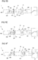
- FIG. 1A to 1F show an example of a checkout system arrangement 1.
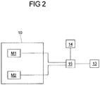
- Fig. 2 shows the connection of some components of the POS system arrangement with one another.
- the cash register system arrangement 1 comprises a goods storage area 16, a goods removal area 17 and a conveyor belt device 10.
- goods W1-W3 that have been deposited in the goods storage area 16 can be transported along a goods feed path P1 into the goods removal area 17.
- the goods removal area 17 in the present case comprises two packing troughs 172, from which goods W1-W3 located therein can be removed and which are separated from each other by a packing tray separation.
- the tray partition comprises an immovable barrier element 170 and a movable barrier element 171 attached thereto.
- the barrier element can be attached to the barrier element in a pivotably articulated manner.
- the packing tray separation can also be realized only by a movable barrier element.
- the conveyor belt device 10 comprises a first belt section 100 and a second belt section 101.
- the second belt section 101 adjoins the first belt section 100.
- Both belt sections 100, 101 can be set in a feed movement and can thus transport goods W1-W3 from the goods deposit area 16 into the goods removal area 17.
- the belt sections 100, 101 form a transition 102 between them. When goods W1-W3 are transported from the first belt section 100 to the second belt section 101, they cross the transition 102 between the belt sections.
- the goods storage area 16 is provided by the first belt section 100.
- the first belt section 100 is formed by a closed, revolving supply belt 105.
- This feed belt 105 is driven by a motor M1 (cf. Fig. 2 ).
- the goods removal area 17 adjoins the second belt section 101.
- the second belt section 101 is arranged between the first belt section 100 and the goods removal area 17.
- the cash register system arrangement 1 further comprises a goods detection device in the form of a portal scanner 13.
- the portal scanner 13 is arranged on the second belt section 101 of the conveyor belt device 10.
- the portal scanner 13 is arranged approximately centrally on the second belt section 101 (or halfway between the first belt section 100 of the conveyor belt device 10 and the goods removal area 17).
- the second belt section 101 is formed by a closed, revolving transport belt 104, by means of which goods W1-W3 can be transported away from the transition 102 and fed to the portal scanner 13.
- the discharge belt 104 is driven by a motor M2.
- the portal scanner 13 is arranged at a distance from the transition 102 between the two belt sections 100, 101.
- the portal scanner 13 comprises one or more means for detecting goods that are transported by the portal scanner 13.
- the portal scanner 13 can comprise a plurality of optical scanning means in order to recognize barcodes or similar markings on the goods W1-W3 and thus to determine the type and number of goods W1-W3.
- the individual prices of the goods W1-W3 and a sum to be paid by the customer can be determined on the basis of the type and number of the goods W1-W3 of a customer.
- the cash register system arrangement 1 comprises a control device 15. This is, as in FIG Fig. 2 shown, connected to the motors M1, M2 of the conveyor belt device 10, to the portal scanner 13 and to the sensor device 14. The connection is made via control lines, for example.
- the motors M1, M2 of the conveyor belt device 10 could also be controlled by a control unit not shown in the figures (for example a programmable logic controller which, if necessary, also controls other functions of the cash register system arrangement, not shown), which in turn is connected to the control device 15 and receives signals from it.
- a control unit not shown in the figures (for example a programmable logic controller which, if necessary, also controls other functions of the cash register system arrangement, not shown), which in turn is connected to the control device 15 and receives signals from it.
- the belt section 100 or belt section 101 can be realized by some other means than a closed, revolving transport belt, such as a roller conveyor or a roller conveyor or roller carpet.
- the control device 15 is only in Figure 1A shown schematically and connected to the conveyor belt device 10, the portal scanner 13 and the sensor device 14 in a suitable manner, for example by electrical control cables, via an RS-232 interface, an RS-485 interface and / or a CAN bus.
- the control device 15 can also be integrated, for example, in the portal scanner 13 or in the sensor device 14, which then also serves as a control device.
- the control device 15 is arranged at a distance from the rest of the cash register system arrangement 1.
- control device 15 is connected to the cash register system arrangement 1 (or its individual components controlled by the control device 15) via suitable means, eg via electrical control cables, via an RS-232 interface, an RS-485 interface and / or a CAN bus.
- suitable means eg via electrical control cables, via an RS-232 interface, an RS-485 interface and / or a CAN bus.
- the goods W1-W3 of the various customers are thereby separated from one another by means of goods dividers 11A, 11B.
- the goods dividers 11A, 11B enable certain goods to be assigned to the various customers.
- goods W1 from a first customer, goods W2 from a second customer and goods W3 from a third customer are shown schematically.
- the goods W1-W3 are separated from one another by two goods dividers 11A, 11B.
- the product dividers 11A, 11B are essentially elongated, in particular rod-shaped.
- the product dividers 11A, 11B are approximately so long that they span a large part of the width of the first and second belt section 100, 101 transversely to the goods feed deposit P1 when they are arranged essentially transversely to the goods feed path P1.
- the goods dividers 11A, 11B are, for example, essentially square, rectangular or triangular in cross section.
- the goods dividers 11A, 11B each include a machine-readable code.
- the machine-readable code can be read out by means of an electromagnetic field, which is e.g. provided by a sensor.
- the machine-readable codes are each provided by an RFID tag 110.
- the RFID tag can be formed by a known 13.56 MHz transponder.
- the already mentioned sensor device 14 is arranged at the end of the first belt section 100 of the conveyor belt device 10.
- the sensor device 14 is provided on the first belt section 100 adjacent to the transition 102 between the first and second belt sections 100, 101 of the conveyor belt device 10.
- the sensor device 14 comprises a detection area 141 (in the Figures 1A to 1F shown in dashed lines).
- the sensor device 14 further comprises a sensor in the form of an RFID antenna 140.
- the RFID antenna 140 is designed to recognize RFID tags 110 of a divider 11A, 11B (or several divider 11A, 11B) and to read out its machine-readable code if the divider 11A, 11B is located in the detection area 141 of the sensor device 14.
- the RFID antenna 140 of the In the present case, the sensor device 14 is arranged under the conveyor belt of the first belt section 100, ie the conveyor belt of the first belt section 100 is located between the goods W1-W3 placed thereon and the RFID antenna 140 of the sensor device 14 arranged below.
- the machine-readable code of the RFID tags 110 includes a UID, by means of which each goods divider 11A, 11B can be uniquely identified. If necessary, individual items of goods can also include an RFID tag.
- the control device 15 comprises a list of UIDs of the goods dividers 11A, 11B and can thus distinguish goods dividers 11A, 11B from goods with RFID tags.
- the portal scanner 13 also includes a sensor in the form of an RFID antenna 130 and an associated detection area 131.
- the design and function of the RFID antenna 130 correspond to the design and function of the RFID antenna 140 of the sensor device 14, so that reference is made to the corresponding description .
- the RFID antenna 130 of the portal scanner 13 is arranged in the area of the portal scanner 13 on the second belt section 101 of the conveyor belt device 10.
- FIG. 1A three customers have placed their goods W1-W3 in the goods storage area 16 one behind the other on the first belt section 100 of the conveyor belt device 10.
- a goods divider 11A was placed by one of the customers.
- the goods divider 11A is aligned essentially perpendicular to the goods feed path P1.
- another goods divider 11B has been placed between the goods W2, W3 of the second and third customers.
- the goods W1-W3 of the individual customers are thus separated from one another by the goods dividers 11A, 11B.
- the control device 15 controls the first belt section 100 of the conveyor belt device 10 in such a way that it executes a feed movement at a first speed V1.
- the control device 15 also controls the second Belt section 101 of the conveyor belt device 10 in such a way that it executes a feed movement at a second speed V2.
- the feed movements take place along the goods feed path P1 in the direction from the goods depositing area 16 to the goods removal area 17.
- the first speed V1 is lower than the second speed V2.
- the first speed V1 can be, for example, approximately two thirds, half or one third of the second speed V2.
- the first speed V1 is in the range from 10 cm / s to 20 cm / s.
- the second speed V2 can be 32 cm / s, for example.
- the cash register system arrangement 1 can comprise a frequency converter. It can be provided that the control unit 15 is designed to apply analog signals to the frequency converter. Specifically, the control unit 15 can be connected to the frequency converter with the following electrical lines: with a first control line, a second control line and a ground line. The control unit 15 can provide an electrical voltage of 0 V or 24 V on the first control line in order to switch a motor on or off. The control unit 15 can provide different voltages on the second control line in order to set a rotational speed of the motor. In particular, a voltage of 5 V can be provided for a low rotational speed when a product divider 11A, 11B is detected by the sensor device 14. Accordingly, a voltage of 10 V can be provided for a higher rotational speed. The speed of a feed movement of a conveyor belt results from the speed of rotation of the motor.
- control device 15 provides signals to a programmable logic controller, which controls the frequency converter as a function of these signals.
- the higher speed of the feed movement of the second belt section 101 compared to the first belt section 100 means that the goods W1-W3 on the second belt section 101 are at a greater distance from one another than on the first belt section 100.
- Figure 1B were the goods W1-W3 opposite Figure 1A already a certain distance along the goods feed path P1 in the direction of the goods removal area 17 transported. Some of the goods W1 of the first customer have already crossed the transition 102 between the first and the second belt section 100, 101 and are conveyed by the second belt section 101. Both goods dividers 11A, 11B are still outside the detection area 141 of the sensor device 14 Figure 1C were the goods W1-W3 opposite Figure 1B transported a certain further distance. All the goods W1 of the first customer have crossed the transition 102 between the first and the second belt section 100, 101 and are conveyed by the second belt section 101.
- the goods separator 11A arranged between the goods W1, W2 of the first and second customer has already been partially transported into the detection area 141 of the sensor device 14 and is now detected by the RFID antenna 140 of the sensor device 14.
- the information captured by the RFID antenna 140 is provided to the control device 15. If the control device 15 detects the UID of a goods separator 11A, 11B, it reduces the speed of the feed movement of the first belt section 100 to a speed V3 which is lower than the speed V1. In one embodiment, this could be reduced, for example, from 20 cm / s to a value for V3 between 10 cm / s and 12 cm / s, in particular 10 cm / s. In addition, it can optionally be provided that the control device 15 also reduces the speed of the feed movement of the first belt section 100 when a large number of goods dividers 11 are detected at short intervals. The evaluation of all tags could otherwise lead to too long a delay.
- Figure 1D were the goods W1-W3 opposite Figure 1C transported over a certain distance.
- the goods separator 11A is still partially in the detection area 141 of the sensor device 14 between the goods W1, W2 of the first and second customers.
- the control device 15 therefore keeps the speed of the feed movement of the first belt section 100 at the speed lower than the speed V1 V3.
- the speed of the feed movement of the second band section 101 is still V2.
- Part of the goods W1 of the first customer has in Figure 1D already crossed the portal scanner 13. The type and number of these goods were recorded by the portal scanner 13 as it passed through.
- the goods divider 11A leaves the detection area 141 of the sensor device 14 between the goods W1, W2 of the first and second customer, as in FIG Figure 1E shown.
- the RFID antenna 140 of the sensor device 14 thus detects the divider 11A no more.
- the control device 15 stops the first belt section 100.
- the control device 15 preferably brings the first belt section 100 to a standstill within 500 ms after the product separator 11A leaves the detection area 141.
- Goods W2 of the second customer following the goods separator 11A remain on the now stationary first belt section 100.
- the goods separator 11A has left the detection area 141 of the sensor device 14 arranged on the first belt section 100 and adjacent to the transition 102 and is therefore already on the second belt section 101.
- the goods W1 of the first customer and the goods separator 11A following these goods W1 are transported to the goods removal area 17 by the second belt section 101, which is still operated at speed V2. In doing so they pass the portal scanner 13.
- the goods divider 11A following the goods W1 of the first customer has in Figure 1F the detection area 131 of the portal scanner 13 has already passed. It was detected by the RFID antenna 130 of the portal scanner 13. The information captured by the RFID antenna 130 of the portal scanner 13 is provided to the control device 15. Thereupon the control device 15 has set the first band section 100 again in a feed movement at the speed V1. Thereupon, the transport of the goods W2 of the second customer begins by the portal scanner 13 in a manner analogous to the transport of the goods W1 of the first customer described above. Before the goods W2 of the second customer reach the goods removal area 17, the control device 15 controls the movable barrier element 171 in such a way that it pivots and releases the other of the two packing trays 172. The first customer thus has enough time to remove his goods W1 from the goods removal area 17.
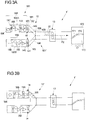
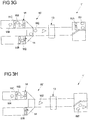
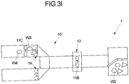
- FIGS 3A-3I show a further embodiment of a cash register system arrangement 1 'with a conveyor belt device 10'. This corresponds in some parts to the exemplary embodiment of the cash register system arrangement 1 according to FIG Figures 1A-1F , wherein like reference numerals indicate corresponding components for their description to the description of the embodiment of the cash register system arrangement 1 according to FIG Figures 1A-1F is referred.
- the POS system arrangement 1 ' accordinging to Figures 3A-3I comprises a first belt section 100 'with a first and a second feed belt 105A, 105B and thus two goods storage areas 16.
- the two feed belts 105A, 105B of the first belt section 100' are arranged essentially parallel to one another and to the discharge belt 104 of the second belt section 101 '.
- the conveyor belt device 10' of the cash register system arrangement 1 ' comprises a connecting section 103 assigned to a second belt section 101'.
- the conveyor belt device 10 ' forms a branched goods feed path P2 which connects the two parallel feed belts 105A, 105B of the first belt section 100' with the second belt section 101 '.
- a transition 102 is formed between each of the two feed belts 105A, 105B of the first belt section 100 'and the connecting section 103.
- Goods W1-W4 which cross one of the transitions 102 can be transported through the connecting section 103 to the removal belt 104.
- the connecting section 103 is formed, for example, by one or more conveyor belts and / or by at least one ramp.
- slopes 106 are arranged on the connecting section 103.
- the bevels 106 each extend between a lateral edge of a feed belt 105A, 105B to a lateral edge of the discharge belt 104.
- the bevels 106 serve to guide the goods W1-W4 to changes in direction of the goods feed path P2.
- the bevels 106 serve to arrange goods W1-W4, which are positioned next to one another on the conveyor belt device 10 '(transversely to the direction of goods advance), one behind the other along the goods advance path P2.
- a sensor device 14 is arranged adjacent to each of the transitions 102 on each of the feed belts 105A, 105B of the first belt section 100 ′.
- the sequence of the feed of goods W1-W4 from four different customers is as follows. First, the control device 15 displaces one of the two feed belts 105A, 105B of the first belt section 100 'in a feed movement (at the first speed V1). In the present example, the first feed belt 105A illustrated above is first set in a feed movement. As a result, the goods W1 of the first customer are transported via the connecting section 103 to the removal belt 104 of the second belt section 101 ', cf. Figures 3A-3D .
- the control device 15 slows down the feed speed of the first tape section.
- the control device 15 stops the first feed belt 105A of the first belt section 100 ', cf. Figure 3E .
- the control device 15 sets the second feed belt 105B of the first belt section 100 'into a feed movement ( with speed V1), cf. Figure 3F .
- the second customer's goods W2 are then transported by the portal scanner 13. So that the goods W1, W2 of the first and second customer do not mix in the goods removal area 17, the control device 15 controls the movable barrier element 171 so that it swivels and closes the packing tray 172 into which the goods W1 of the first customer were transported. This takes place before the goods W2 of the second customer arrive at the goods removal area 17, cf. Figure 3G . The goods W2 of the second customer are thereby transported by the movable barrier element 171 into the second packing tray 172.
- the control device 15 reduces the speed of the second feed belt 105B, cf. Figure 3H .
- control device 15 stops the second feed belt 105B, cf. Figure 3I .
- the procedure for transporting the goods W3 of the third customer is then analogous to the transport of the goods W1 of the first customer.
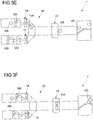
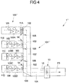
- FIG. 4 shows a further exemplary embodiment of a checkout system arrangement 1 ′′. This corresponds in some parts to the exemplary embodiments of the checkout system arrangement 1; 1 ′ according to FIG Figures 1A-1F and Figures 3A-3I , wherein like reference numerals indicate corresponding components, with respect to which reference is made to the preceding description.
- the POS system arrangement 1 "of the Fig. 4 comprises a branched goods feed path P3, which in the present case connects four feed belts 105A-105D of a first belt section 100 "with a second belt section 101".
- the second belt section comprises a connecting section 103 ′, which forms a transition 102 with each of the feed belts 105A-105D of the first belt section 100 ′′.
- a plurality of bevels 106 are provided on the connecting section 103 '.
- a bevel 106 is arranged adjacent to each of the transitions 102.
- an incline 106 extends from a corner at which each of the transitions 102 meets an edge (lateral along the feed direction) of the respective first feed belts 105A-105D of the first belt section 100 ′′.
- the inclines 106 are also located there arranged where the goods feed path P3 performs a change in direction.
- the connecting section 103 ' is designed as a conveyor belt.
- the infeed belts 105A-105D of the first belt section 100 ′′ are aligned essentially parallel to the outfeed belt 104 and perpendicular to the connecting section 103 '. Otherwise, the infeed belts 105A-105D essentially correspond to the infeed belts 105; 105A, 105B of the exemplary embodiments of the cash register system arrangements 1; 1' according to the Figures 1A-1F ; 3A-3I . Reference is also made to the description there with regard to the design and functioning of the portal scanner 13, the sensor devices 14 and the control device 15.
- a particularly large number of customers can display their goods W1-W4 at the same time.
- the goods W1-W4 are transported to the portal scanner 13 one after the other. This can be used particularly efficiently.
- Several goods dividers 11A-11D separate goods W1-W4 of the customers on the infeed belts 105A-105D from goods of preceding or following customers.
- a goods removal area 17 (not shown here) can optionally be connected to the cash register system arrangement 1 ′′.
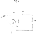
- Fig. 5 shows a side view of the end region of the feed belt 105 of the first belt section 100; 100 '; 100 ", which in the exemplary embodiments of the cash register system arrangements 1; 1 ';1" described above is attached to the respective second belt section 101; 101 '; 101 ′′ (and thus each forms a transition 102).
- the feed belt 105 is deflected on a deflection roller 107.
- the deflection roller 107 is articulated on a frame 108.
- the frame 108 is made of a metal, for example aluminum or sheet steel produced.
- the RFID antenna 140 of the sensor device 14 is arranged below the feed belt 105. It is also arranged at a distance from the feed belt 105. The distance is between 1.5 cm and 10 cm. At such a distance, an RFID tag 110 of a goods divider 11A-11D can be recognized up to approximately 2.5 cm above the infeed belt 105.
- the RFID antenna 141 is provided so that it can be adjusted in height (so that the distance from the feed belt 105 can be adjusted). This ensures that the RFID tags are recorded as precisely as possible.
- the RFID antenna 140 extends essentially over the entire width of the feed belt 105. In this case, however, the RFID antenna 140 can be somewhat narrower than the feed belt 105 (for example about 2 cm). There is preferably a distance of approximately 1 cm on both sides between the RFID antenna 140 and the frame 108. As a result, goods dividers 11A-11D can be fed back laterally on the infeed belt 105 without being detected by the RFID antenna. Thus, when a merchandise divider is returned (as is customary in cash register systems), there is no disruption of the cash register system arrangement 1; 1';1".
- the detection area 141 of the sensor arrangement 14 extends (when used as intended) above the RFID antenna 140.
- a plastic window e.g. made of Plexiglas, polycarbonate, composite material HPL, etc. is not shown here .ä.) arranged between the RFID antenna and the feed belt 105.
- the RFID antenna 141 is shielded against interference from other components of the POS system arrangement (e.g. a conveyor belt motor) by means of suitable shielding, e.g. by using shielded and / or cable connections provided with ferrite cores.
- Fig. 6 shows a flowchart according to which each feed belt of the cash register system arrangements 1, 1 ′, 1 ′′ described above can be controlled by means of the control device 15.
- step S1 the control device 15 is activated (step S1). If the controlled POS system arrangement comprises more than one infeed belt, only one of the infeed belts is active at the same time in order to transport goods to the outfeed belt.
- step S2 it is checked whether the status of the feed belt to be controlled is currently "active". If this is not the case, the speed of the feed belt is set to zero in step S3 (or kept at zero), whereupon the process continues again in step S2. The feed belt is therefore stopped or left at a standstill. If, on the other hand, the status of the feed belt is "active", a transport process begins (beginning with step S4).
- the status of the infeed belt is set to "active", e.g. manually via the control device 15 (e.g. a PLC), for example by inputting an operator.
- setting the status of the feed belt to "active” consists in setting a corresponding status indicator ("flag") of the control device 15.
- the flag is set to "active” automatically when an event occurs, for example when an event occurs (for example by means of a proximity sensor) detected approach of a customer to the POS system arrangement. The flag is only set when a purchase process is to begin.
- step S4 it is checked whether the sensor device 14 is currently detecting a divider 11A-11D.
- step S4 If a goods divider 11A-11D is currently detected by the sensor device 14 in step S4, the process continues with step S5.
- step S8 If no goods separator 11A-11D is currently detected by the sensor device 14 in step S4, then the process continues with step S8. There, by querying a memory provided for this purpose, it is checked whether the sensor device 14 has already detected a goods divider 11A-11D in the current transport process. If it has not yet detected a goods divider 11A-11D in the current transport process, the speed of the feed belt is set to V1 in step S9 and the process continues with step S4.
- the speed V1 is e.g. between 20 cm / s and 22 cm / s.
- step S8 If it is recognized in step S8 by querying the memory that a goods divider 11A-11D has already been detected by the sensor device 14 at least once in the current transport process, the control device 15 pauses in step S10, e.g. for 500 ms or for up to 500 ms. The process then continues with step S11.
- step S11 If a goods divider is detected again by the sensor device 14 in step S11, the process continues with step S5. In this way, short interruptions in the detection of the divider 11A-11D are taken into account.
- step S11 If no goods separator 11A-11D is detected by the sensor device 14 in step S11, the control device 15 sets the speed of the feed belt to zero (or keeps it at zero) and goes to step S2. In step S5, the feed belt is set at a speed V3. The speed V3 is e.g. between 10 cm / s and 12 cm / s. The process then continues with step S6. In step S6 it is checked by querying the memory whether the sensor device 14 has already detected a goods divider 11A-11D in the current transport process. If the goods divider 11A-11D has not yet been detected, the information is stored in the memory in step S7 that a goods separator 11A-11D has now been detected. The procedure then continues again with step S4.
- a checkout system arrangement can also have a number of conveyor belts of the first belt sections (not shown here), for example three, five or six.
- the conveyor belts of the first belt sections of the cash register system arrangements are arranged parallel to one another.
- the goods can include RFID tags and can be detected by means of the RFID antenna of the goods detection device.
- a classic, staff-operated registration station can also be used as the goods registration device.
- the sensor (the RFID antenna) of the sensor device does not necessarily have to be arranged below the conveyor belt, but can alternatively generally also be arranged above the conveyor belt.
- machine-readable codes can also be attached to goods dividers, which are then read out by a corresponding other type of sensor.
- the machine-readable code can be used as a barcode, QR code or other detectable (e.g. visible) marker (e.g. in the form of a graphic, a clear pattern or image) or in the form of a digital watermark (especially imperceptible to the human eye) (e.g. from DigiMarc, Portland, USA).
- An optical detection unit then serves as the sensor.
- the RFID antenna can be arranged within a ferrite cage or housing that is open on one side.
- the open side of the ferrite cage or housing points towards the detection area. If the RFID antenna is arranged below the feed belt, the open side can, for example, point upwards.
- the ferrite housing can in particular be designed in the form of a cuboid made of ferrite plates. The size of the opening of the ferrite cage or housing can be adjustable.
- the size of the detection area can depend, for example, on the specific properties of the RFID antenna. Furthermore, the size of the detection area can be adjusted, for example by adjusting the size of the opening of a ferrite cage or housing and / or by arranging a window or a boundary made of metal, in particular metal plates, between the RFID antenna and the feed belt.
Description
Die Erfindung betrifft eine Kassensystemanordnung nach dem Oberbegriff des Anspruchs 1 und ein Verfahren zum Betreiben einer Kassensystemanordnung nach dem Oberbegriff des Anspruchs 8.The invention relates to a checkout system arrangement according to the preamble of
Eine derartige Kassensystemanordnung weist eine Transportbandvorrichtung und eine Warenerfassungseinrichtung auf. Dabei umfasst die Transportbandvorrichtung mindestens einen Bandabschnitt, der zum Transport von darauf befindlichen Waren entlang eines Warenvorschubpfades in eine Vorschubbewegung versetzt werden kann, wobei die Waren entlang des Warenvorschubpfades voneinander durch mindestens einen Warentrenner separierbar sind. Die Warenerfassungseinrichtung ist ausgebildet und vorgesehen, Waren zu erfassen, die durch die Transportbandvorrichtung transportiert werden.Such a cash register system arrangement has a conveyor belt device and a goods detection device. The conveyor belt device comprises at least one belt section which can be set in a feed movement for the transport of goods located thereon along a goods feed path, the goods being separable from one another by at least one goods divider along the goods feed path. The goods detection device is designed and provided to detect goods which are transported by the conveyor belt device.
Eine Kassensystemanordnung der vorgenannten Art ist aus der
Nachteilig ist bei der bekannten Kassensystemanordnung, dass dicht nebeneinander auf dem Transportband abgelegte Waren durch die Abtasteinrichtung gegebenenfalls nicht eindeutig erkannt werden können, beispielsweise weil ein erstes Warenstück eine optische Sichtachse zwischen der Abtasteinrichtung und einer als optischer Code ausgeführten maschinenlesbaren Markierung auf einem zweiten Warenstück verdeckt. Eine mögliche Folge ist eine unzuverlässige Warenerkennung der bekannten Kassensystemanordnung. Kunden der Kassensystemanordnung sind zudem häufig nicht gewohnt oder geübt, Waren in ausreichenden Abständen zueinander auf dem Transportband zu platzieren, sodass eine zuverlässige Erkennung aller Waren durch die Abtasteinrichtung sichergestellt wird. Um einen möglichst hohen Komfort für die Kunden zu gewährleisten, ist es daher wünschenswert, eine zuverlässige Warenerkennung sicherzustellen, auch wenn ein Kunde seine Waren in dichten Abständen zueinander auf dem Transportband ablegt.A disadvantage of the known cash register system arrangement is that goods placed close to one another on the conveyor belt may not be affected by the scanning device can be clearly recognized, for example because a first item of goods conceals an optical line of sight between the scanning device and a machine-readable marking in the form of an optical code on a second item of goods. One possible consequence is an unreliable goods recognition of the known cash register system arrangement. In addition, customers of the POS system arrangement are often not used to or experienced in placing goods on the conveyor belt at a sufficient distance from one another, so that reliable detection of all goods by the scanning device is ensured. In order to ensure the greatest possible comfort for the customer, it is therefore desirable to ensure reliable goods recognition, even if a customer places his goods on the conveyor belt at close spacing from one another.
Darüber hinaus sind auch aus den Dokumenten
Aufgabe der vorliegenden Erfindung ist es, die bekannte Kassensystemanordnung zu verbessern, insbesondere die Zuverlässigkeit der Warenerkennung zu verbessern.The object of the present invention is to improve the known cash register system arrangement, in particular to improve the reliability of the goods recognition.
Diese Aufgabe wird durch einen Gegenstand mit den Merkmalen des Anspruchs 1 gelöst.This object is achieved by an object with the features of
Danach sind mindestens eine Sensoreinrichtung sowie eine Steuerungseinrichtung vorgesehen, wobei die mindestens eine Sensoreinrichtung entlang des Warenvorschubpfades von der Warenerfassungseinrichtung beabstandet angeordnet ist und einen Sensor und einen Erfassungsbereich umfasst. Die Sensoreinrichtung ist ausgebildet und vorgesehen, zu erfassen, ob sich ein Warentrenner im Erfassungsbereich befindet oder nicht. Die Steuerungseinrichtung ist ausgebildet und vorgesehen, die Vorschubbewegung des Bandabschnitts der Transportbandvorrichtung in Abhängigkeit von der Erfassung des Warentrenners im Erfassungsbereich der Sensoreinrichtung zu steuern.According to this, at least one sensor device and a control device are provided, the at least one sensor device being arranged along the goods feed path at a distance from the goods detection device and comprising a sensor and a detection area. The sensor device is designed and provided to detect whether a goods divider is in the detection area or not. The control device is designed and provided to control the feed movement of the belt section of the conveyor belt device as a function of the detection of the goods separator in the detection area of the sensor device.
Durch die beabstandete Anordnung der Sensoreinrichtung (insbesondere des Erfassungsbereichs) von der Warenerfassungseinrichtung ist es möglich, durch Erfassung des Warentrenners den Warenvorschub an einer von der Warenerfassungseinrichtung (entlang des Warenvorschubpfades) beabstandeten Stelle zu überwachen. Die Information, ob sich der Warentrenner im Erfassungsbereich der Sensoreinrichtung befindet oder nicht, kann verwendet werden, um die Effizienz und/oder die Zuverlässigkeit der Warenerkennung der Kassensystemanordnung zu verbessern.Due to the spaced arrangement of the sensor device (in particular the detection area) from the goods detection device, it is possible, by detecting the goods divider, to feed the goods on one of the goods detection device (along the goods feed path) to monitor spaced-apart place. The information as to whether or not the goods divider is in the detection range of the sensor device can be used to improve the efficiency and / or the reliability of the goods recognition of the checkout system arrangement.
Die Kassensystemanordnung kann allgemein als Checkout-Platz im Groß- oder Einzelhandel eingesetzt werden, beispielsweise in Warenhandelsmärkten wie Baumärkten, Supermärkten, usw.The POS system arrangement can generally be used as a checkout point in the wholesale or retail trade, for example in commodity markets such as hardware stores, supermarkets, etc.
Insbesondere kann die Warenerfassungseinrichtung der Kassensystemanordnung als Portalscanner ausgebildet sein, z.B. als 360°-Portalscanner mit optischer Erfassung der Art und Anzahl der Waren. Ein Portalscanner stellt ein Portal bereit, durch das Waren transportierbar sind. Während des Transports durch das Portal werden Art und Anzahl der Waren automatisch erkannt. So ist ein besonders effizienter Kassiervorgang möglich. Alternativ kann die Kassensystemanordnung aber auch mit einer durch Personal (manuell) bedienten Erfassungseinrichtung verwendet werden.In particular, the goods detection device of the cash register system arrangement can be designed as a portal scanner, e.g. as a 360 ° portal scanner with optical detection of the type and number of goods. A portal scanner provides a portal through which goods can be transported. During the transport through the portal, the type and number of goods are automatically recognized. This enables a particularly efficient checkout process. Alternatively, however, the cash register system arrangement can also be used with a detection device operated (manually) by personnel.
Die Sensoreinrichtung ist der Warenerfassungseinrichtung (entlang des Warenvorschubpfades) vorgelagert angeordnet. Bestimmungsgemäß wird der Warentrenner von einem Kunden derart auf der Transportbandvorrichtung abgelegt, dass er sich entlang des Warenvorschubpfades zwischen den Waren des Kunden und den Waren eines vorangehenden oder nachkommenden anderen Kunden befindet. Damit kann der Warentrenner zugleich das Ende der Waren des einen Kunden und den Anfang der Waren des nächsten Kunden anzeigen. Wenn die Sensoreinrichtung der Warenerfassungseinrichtung (in einem bekannten Abstand) vorgelagert angeordnet ist, kann die Steuerungseinrichtung ermitteln, wie lange der mindestens eine Bandabschnitt der Transportbandvorrichtung mit einer bestimmten Geschwindigkeit eine Vorschubbewegung ausführen muss, damit alle Waren des einen Kunden die Entfernung zwischen dem Erfassungsbereich der Sensoreinrichtung und der Warenerfassungseinrichtung zurückgelegt hat.The sensor device is arranged upstream of the goods detection device (along the goods feed path). As intended, the goods separator is placed on the conveyor belt device by a customer in such a way that it is located along the goods feed path between the goods of the customer and the goods of a preceding or following other customer. This means that the divider can display the end of the goods for one customer and the beginning of the goods for the next customer at the same time. If the sensor device is arranged upstream of the goods detection device (at a known distance), the control device can determine how long the at least one belt section of the conveyor belt device has to carry out a feed movement at a certain speed so that all of the goods of one customer cover the distance between the detection area of the sensor device and the goods detection device has traveled.
Zusätzlich kann die Sensoreinrichtung der Warenerfassungseinrichtung aber auch (entlang des Warenvorschubpfades) nachgelagert angeordnet sein. So könnte z.B. ermittelt werden, ob der Warentrenner wie erwartet mittels der Transportbandvorrichtung transportiert wird oder ob z.B. ein Warenrückstau vorliegt.In addition, the sensor device can also be arranged downstream of the goods detection device (along the goods feed path). For example, it could be determined whether the goods separator is being transported by means of the conveyor belt device as expected or whether, for example, there is a backlog of goods.
Die Sensoreinrichtung kann ausgebildet sein, durch Auslesen eines am Warentrenner vorgesehenen maschinenlesbaren Codes mittels des Sensors zu erfassen, ob sich der Warentrenner im Erfassungsbereich befindet. Hierdurch ist es möglich, einen Warentrenner besonders eindeutig zu erfassen.The sensor device can be designed to detect by means of the sensor, by reading out a machine-readable code provided on the goods divider, whether the goods divider is in the detection area. This makes it possible to detect a divider particularly clearly.
Der maschinenlesbare Code kann insbesondere mit Hilfe von elektromagnetischen Feldern ausgelesen werden. Ein elektromagnetisches Feld kann dabei von dem Sensor der Sensoreinrichtung erzeugt werden.The machine-readable code can in particular be read out with the aid of electromagnetic fields. An electromagnetic field can be generated by the sensor of the sensor device.
Der am Warentrenner vorgesehene maschinenlesbare Code kann auf verschiedene Weise bereitgestellt werden. Vorzugsweise wird der maschinenlesbare Code durch einen RFID-Tag bereitgestellt. Der Sensor der Sensoreinrichtung ist bevorzugt als RFID-Antenne zum Auslesen des RFID-Tags des Warentrenners ausgebildet. So kann die Sensoreinrichtung einen Warentrenner erkennen, ohne dass eine optische Sichtverbindung zwischen dem Sensor und dem Warentrenner vorliegen muss. Die RFID-Antenne und der RFID-Tag können insbesondere zur RFID-Kommunikation in einem Frequenzband mit 13,56 MHz ausgebildet sein. Um eine möglichst gute Erfassung des RFID-Tags zu gewährleisten, sollte der Warentrenner aus einem nicht-metallischen Material hergestellt sein, um Dämpfungen oder Abschattungen des Antennenfeldes zu vermeiden. In diesem Falle kann sich das RFID-Tag im Inneren des Trennstabs befinden (idealerweise mittig im inneren Kern), um zu gewährleisten, so dass das Tag in jeder Lage und Drehung des Stabes gleichermaßen detektiert werden kann. Alternativ können aber auch RFID-Tags, ausgestattet mit einer Kunststoffisolation (bspw. in Form einer dünnen Kunststofffolie), auf eine etwaige metallische Oberfläche des Trennstabs (von außen) aufgebracht werden. Der Warentrenner kann länglich ausgebildet sein. Der RFID-Tag kann entlang der Längserstreckung des Warentrenners mittig angeordnet sein. Alternativ kann sich der RFID-Tag z.B. im Wesentlichen über die gesamte Längserstreckung des Warentrenners erstrecken. Beispielsweise kann ein unter der Bezeichnung TW-R16-B128 erhältlicher RFID-Tag eingesetzt werden. Für eine optimierte Erfassung kann ferner ein gewölbter RFID-Tag vorgesehen sein.The machine-readable code provided on the divider can be provided in various ways. The machine-readable code is preferably provided by an RFID tag. The sensor of the sensor device is preferably designed as an RFID antenna for reading out the RFID tag of the divider. In this way, the sensor device can recognize a goods divider without the need for an optical line of sight between the sensor and the goods divider. The RFID antenna and the RFID tag can be designed in particular for RFID communication in a frequency band of 13.56 MHz. In order to ensure the best possible detection of the RFID tag, the divider should be made of a non-metallic material in order to avoid dampening or shadowing of the antenna field. In this case, the RFID tag can be located inside the separating rod (ideally in the middle of the inner core) in order to ensure that the tag can be detected equally in every position and rotation of the rod. Alternatively, however, RFID tags, equipped with plastic insulation (for example in the form of a thin plastic film), can be applied to any metallic surface of the separating rod (from the outside). The divider can be elongated. The RFID tag can be arranged centrally along the longitudinal extension of the goods divider. Alternatively, the RFID tag can, for example, extend essentially over the entire length of the divider. For example, an RFID tag available under the designation TW-R16-B128 can be used. A curved RFID tag can also be provided for optimized detection.
Alternativ oder zusätzlich kann der maschinenlesbare Code aber beispielsweise auch als Strichcode oder als sogenannter QR-Code ausgebildet sein. Die Sensoreinrichtung umfasst dann bevorzugt einen oder mehrere als optische Erfassungsmittel ausgebildete Sensoren zum Auslesen des Strich- oder QR-Codes, wobei in diesem Fall unter einem Auslesen das Lesen eines Strich- oder QR-Codes gemeint ist.As an alternative or in addition, the machine-readable code can also be designed as a bar code or as a so-called QR code, for example. The sensor device then preferably comprises one or more sensors designed as optical detection means for reading out the bar code or QR code, in which case reading means reading a bar code or QR code.
Die Kassensystemanordnung kann eine Mehrzahl, insbesondere eine Vielzahl von Warentrennern umfassen, an denen jeweils ein maschinenlesbarer Code vorgesehen ist. Bevorzugt unterscheiden sich mehrere - insbesondere alle - maschinenlesbaren Codes voneinander. So können die mehreren Warentrenner durch die Sensoreinrichtung voneinander unterschieden und eindeutig identifiziert werden. Die Sensoreinrichtung kann ausgebildet sein, mehrere sich gleichzeitig im Erfassungsbereich befindliche Warentrenner zu erfassen (und ggf. auch eindeutig zu identifizieren). Die maschinenlesbaren Codes können beispielsweise eine UID (unique identifier) umfassen. Durch Auslesen der UID kann die Steuerungseinrichtung Warentrenner von Warenstücken unterscheiden, die ebenfalls RFID-Tags umfassen können. Hierzu kann die Steuerungseinrichtung eine (ggf. nachträglich erweiterbare) Liste von UIDs in geeigneter Weise speichern oder mit einer externen Speichereinrichtung verbunden sein. Durch Vergleich der Ausgelesenen UID mit den gespeicherten UIDs kann die Steuerungseinrichtung feststellen, ob die UID einem (oder einem bestimmten) Warentrenner zugeordnet ist. In Abhängigkeit davon kann sie die Vorschubbewegung des Bandabschnitts der Transportbandvorrichtung steuern.The cash register system arrangement can comprise a plurality, in particular a plurality of goods dividers, on each of which a machine-readable code is provided. Several - in particular all - machine-readable codes preferably differ from one another. The sensor device can thus distinguish the multiple goods dividers from one another and clearly identify them. The sensor device can be designed to detect (and, if necessary, also to identify them unambiguously) several goods dividers that are located in the detection area at the same time. The machine-readable codes can include, for example, a UID (unique identifier). By reading out the UID, the control device can distinguish goods dividers from goods, which can also include RFID tags. For this purpose, the control device can store a list of UIDs (which can optionally be expanded at a later date) in a suitable manner or be connected to an external storage device. By comparing the read UID with the stored UIDs, the control device can determine whether the UID is assigned to a (or a specific) divider. Depending on this, it can control the feed movement of the belt section of the conveyor belt device.
Die Warenerfassungseinrichtung kann einen Sensor und einen dem Sensor zugeordneten Erfassungsbereich umfassen. Der Sensor der Warenerfassungseinrichtung ist ausgebildet, den am Warentrenner vorgesehenen maschinenlesbaren Code zu erfassen, wenn sich der Warentrenner im Erfassungsbereich der Warenerfassungseinrichtung befindet. Der Erfassungsbereich der Warenerfassungseinrichtung ist an der Warenerfassungseinrichtung oder benachbart dazu ausgebildet. Insbesondere ist der Erfassungsbereich der Warenerfassungseinrichtung beabstandet vom Erfassungsbereich der Sensoreinrichtung angeordnet. Die Warenerfassungseinrichtung (oder die ggf. damit verbundene Steuerungseinrichtung) kann erkennen, ob sich ein (oder ein bestimmter) Warentrenner im Erfassungsbereich der Warenerfassungseinrichtung befindet oder nicht.The goods detection device can comprise a sensor and a detection area assigned to the sensor. The sensor of the goods detection device is designed to detect the machine-readable code provided on the goods separator when the goods separator is in the detection area of the goods detection device. The detection area of the goods detection device is formed on or adjacent to the goods detection device. In particular, the detection area of the goods detection device is arranged at a distance from the detection area of the sensor device. The goods detection device (or the control device possibly connected to it) can recognize whether a (or a specific) goods divider is located in the detection area of the goods detection device or not.
Die Steuerungseinrichtung kann dazu ausgebildet sein, zumindest einen Bandabschnitt der Transportbandvorrichtung aus einem Stillstand heraus in eine Vorschubbewegung zu versetzen (oder alternativ die Geschwindigkeit der Vorschubbewegung von einer ersten Geschwindigkeit in eine davon verschiedene zweite Geschwindigkeit zu ändern), wenn sie ein Steuersignal empfängt, wenn sie erkennt, dass eine vorbestimmte oder vorbestimmbare Standzeit abgelaufen ist und/oder wenn ein Benutzer einen entsprechenden Befehl an die Steuerungseinrichtung eingibt. Beispielsweise kann ein Betätigungsmittel wie eine Taste vorgesehen sein, welche ein Benutzer (z.B. ein Kunde) betätigen kann, wobei die Steuerungseinrichtung bei Betätigung des Betätigungsmittels den Bandabschnitt der Transportbandvorrichtung in eine Vorschubbewegung versetzt. Ein Steuersignal kann z.B. von einem Packmuldensensor der Kassensystemanordnung bereitgestellt werden, der erkennt, ob eine Packmulde (eines Warenentnahmebereichs der Kassensystemanordnung) mit Waren belegt oder frei ist. Beispielsweise stellt der Packmuldensensor ein Steuersignal bereit, wenn die Packmulde (oder falls mehrere Packmulden vorgesehen sind, eine oder eine bestimmte Packmulde) frei ist.The control device can be designed to move at least one belt section of the conveyor belt device from a standstill into a feed movement (or, alternatively, to change the speed of the feed movement from a first speed to a different second speed) when it receives a control signal when it recognizes that a predetermined or predeterminable idle time has expired and / or when a user inputs a corresponding command to the control device. For example, an actuation means such as a button can be provided which a user (e.g. a customer) can actuate, wherein the control device sets the belt section of the conveyor belt device in a feed movement when the actuating means is actuated. A control signal can be provided, for example, by a packing tray sensor of the checkout system arrangement, which recognizes whether a packing tray (a goods removal area of the checkout system arrangement) is occupied with goods or is free. For example, the packing tray sensor provides a control signal when the packing tray (or, if several packing trays are provided, one or a specific packing tray) is free.
Alternativ oder zusätzlich ist die Steuerungseinrichtung ausgebildet, zumindest einen Bandabschnitt der Transportbandvorrichtung aus einem Stillstand heraus in eine Vorschubbewegung zu versetzen, wenn der Sensor der Warenerfassungseinrichtung einen Warentrenner im Erfassungsbereich der Warenerfassungseinrichtung erfasst.Alternatively or additionally, the control device is designed to move at least one belt section of the conveyor belt device from a standstill into a feed movement when the sensor of the goods detection device detects a goods separator in the detection area of the goods detection device.
Die Steuerungseinrichtung ist ausgebildet, in Abhängigkeit von der Erfassung des Warentrenners im Erfassungsbereich der Sensoreinrichtung (oder alternativ oder zusätzlich im Erfassungsbereich der Warenerfassungseinrichtung) die Vorschubbewegung zumindest eines solchen Bandabschnitts der Transportbandvorrichtung zu steuern, welcher der Warenerfassungseinrichtung entlang des Warenvorschubpfades vorgelagert angeordnet ist. Auf diese Weise kann die Steuerungseinrichtung die Transportbandvorrichtung so steuern, dass die Geschwindigkeit der Warenzufuhr an die Warenerfassungseinrichtung erhöht oder verringert wird, oder dass die Warenzufuhr an die Warenerfassungseinrichtung gestartet oder gestoppt wird, je nachdem ob ein Warentrenner (oder ein bestimmter Warentrenner) an der vorgelagerten Sensoreinrichtung erfasst wird oder nicht.The control device is designed to control the feed movement of at least one belt section of the conveyor belt device which is arranged upstream of the goods detection device along the goods feed path as a function of the detection of the goods separator in the detection area of the sensor device (or alternatively or additionally in the detection area of the goods detection device). In this way, the control device can control the conveyor belt device so that the speed of the goods feed to the goods detection device is increased or decreased, or that the goods feed to the goods detection device is started or stopped, depending on whether a goods divider (or a certain goods divider) is on the upstream Sensor device is detected or not.
Die Transportbandvorrichtung umfasst mindestens einen ersten Bandabschnitt und einen zweiten Bandabschnitt. Der erste Bandabschnitt ist zum Ablegen von Waren ausgebildet und stellt einen Warenablagebereich bereit. Der zweite Bandabschnitt ist zum Zuführen der auf dem ersten Bandabschnitt abgelegten Waren in den Erfassungsbereich der Warenerfassungseinrichtung ausgebildet. Selbstverständlich können auch noch weitere Bandabschnitte vorgesehen sein. Insbesondere kann der erste Bandabschnitt entlang des Warenvorschubpfades dem zweiten Bandabschnitt vorgelagert sein. Wird der so angeordnete erste Bandabschnitt in eine Vorschubbewegung versetzt, führt er darauf abgelegte Waren an den zweiten Bandabschnitt zu.The conveyor belt device comprises at least a first belt section and a second belt section. The first belt section is designed for storing goods and provides a goods storage area. The second belt section is designed for feeding the goods deposited on the first belt section into the detection area of the goods detection device. Of course, further tape sections can also be provided. In particular, the first belt section can be positioned in front of the second belt section along the goods feed path. If the first belt section arranged in this way is set in a feed movement, it feeds goods deposited thereon to the second belt section.
Der erste und der zweite Bandabschnitt können mit unterschiedlichen Vorschubgeschwindigkeiten betrieben werden. Die Steuerungseinrichtung ist ausgebildet, den ersten Bandabschnitt in eine Vorschubbewegung mit einer ersten Geschwindigkeit und den zweiten Bandabschnitt in eine Vorschubbewegung mit einer zweiten Geschwindigkeit zu versetzen. Dabei kann insbesondere vorgesehen sein, dass die zweite Geschwindigkeit größer ist als die erste Geschwindigkeit. Durch die höhere Geschwindigkeit des zweiten Bandabschnitts können die Abstände mehrerer Waren zueinander entlang des Warenvorschubpfades vergrößert werden (es kann eine Warenvereinzelung erreicht werden). Durch größere Abstände zwischen einzelnen Waren ist eine höhere Präzision und Zuverlässigkeit bei der Erfassung der Waren an der Warenerfassungseinrichtung möglich. Die Steuerung der Geschwindigkeiten erfolgt in Abhängigkeit von der Erfassung des Warentrenners im Erfassungsbereich der Sensoreinrichtung.The first and the second belt section can be operated at different feed speeds. The control device is designed to set the first tape section in a feed movement at a first speed and the second tape section in a feed movement at a second speed. It can be provided in particular that the second speed is greater than the first speed. Due to the higher speed of the second belt section, the distances between several goods can be increased along the goods feed path (goods can be separated). Larger distances between individual goods enable greater precision and reliability in the detection of the goods on the goods detection device. The speed is controlled depending on the detection of the divider in the detection area of the sensor device.
Die Steuerungseinrichtung ist dazu ausgebildet, eine Geschwindigkeit der Vorschubbewegung des ersten Bandabschnitts zu reduzieren, während sich der Warentrenner im Erfassungsbereich der Sensoreinrichtung befindet und vom Sensor der Sensoreinrichtung erfasst wird. Durch die reduzierte Geschwindigkeit kann eine zuverlässige Zuordnung von Waren beidseits des Warentrenners zu den jeweiligen Kunden erreicht werden. Sowohl der erste als auch der zweite Bandabschnitt können jeweils in mehrere Teilabschnitte unterteilt sein, die unabhängig voneinander in eine Vorschubbewegung versetzbar sind.The control device is designed to reduce a speed of the feed movement of the first strip section while the goods separator is located in the detection area of the sensor device and is detected by the sensor of the sensor device. Due to the reduced speed, a reliable assignment of goods on both sides of the goods divider to the respective customer can be achieved. Both the first and the second belt section can each be subdivided into a plurality of partial sections which can be set in a feed movement independently of one another.
Ferner ist die Steuerungseinrichtung ausgebildet, den ersten Bandabschnitt zu stoppen, sobald der Warentrenner den Erfassungsbereich der Sensoreinrichtung verlassen hat. Auf diese Weise kann sichergestellt werden, dass Waren, die ggf. dem Warentrenner folgen, nicht weiter transportiert werden. Dabei handelt es sich beispielsweise um Waren des nächsten Kunden.Furthermore, the control device is designed to stop the first belt section as soon as the divider has left the detection area of the sensor device. In this way it can be ensured that goods that may follow the goods separator are not transported further. These are, for example, goods from the next customer.
Der erste Bandabschnitt grenzt an einem Übergang an den zweiten Bandabschnitt an. Der Erfassungsbereich der Sensoreinrichtung ist an dem Übergang zwischen dem ersten und dem zweiten Bandabschnitt angeordnet. So wird durch entsprechende Steuerung der Bandabschnitte ermöglicht, Waren beidseits (entlang des Warenvorschubpfades) des Warentrenners zu separieren, wenn ein Warentrenner am Erfassungsbereich der Sensoreinrichtung erfasst wird.The first band section adjoins the second band section at a transition. The detection area of the sensor device is arranged at the transition between the first and the second strip section. Appropriate control of the belt sections enables goods to be separated on both sides (along the goods feed path) of the goods divider when a goods divider is detected at the detection area of the sensor device.
Der Erfassungsbereich der Sensoreinrichtung kann sich im Wesentlichen über die gesamte Breite (quer zum Warenvorschubpfad an dieser Stelle der Transportbandvorrichtung) des ersten Bandabschnitts erstrecken (z.B. etwa 45 cm). So kann eine hohe Zuverlässigkeit und Präzision bei der Erfassung des Warentrenners erreicht werden.The detection range of the sensor device can extend essentially over the entire width (transversely to the goods feed path at this point of the conveyor belt device) of the first belt section (e.g. about 45 cm). In this way, a high level of reliability and precision can be achieved when detecting the divider.
Der Warenvorschubpfad ist in einer beispielhaften Ausführungsform verzweigt ausgebildet. So umfasst der erste Bandabschnitt mehrere Zufuhrbänder, die mit (demselben) zweiten Bandabschnitt derart verbunden sind, dass Waren von den Zufuhrbändern an den zweiten Bandabschnitt und von diesem weitertransportiert werden können. So können mehrere Kunden gleichzeitig Waren auf der Kassensystemanordnung ablegen und die Waren können von derselben Warenerfassungseinrichtung erfasst werden. Häufig erfolgt die Erfassung von Waren mit einer höheren Geschwindigkeit als das Auflegen von Waren durch Kunden, sodass durch den Einsatz mehrerer erster Bandabschnitte die Auslastung der Warenerfassungseinrichtung erhöht werden kann.In an exemplary embodiment, the goods feed path is branched. Thus, the first belt section comprises a plurality of supply belts which are connected to (the same) second belt section in such a way that goods can be transported from the supply belts to and from the second belt section. In this way, several customers can store goods on the cash register system arrangement at the same time and the goods can be recorded by the same goods detection device. Often, goods are captured at a higher speed than goods are placed on by customers, so that the utilization of the goods capture device can be increased by using several first belt sections.
Es sei angemerkt, dass die Kassensystemanordnung auch mehrere Sensoreinrichtungen umfassen kann. Diese können insbesondere entlang des Warenvorschubpfades voneinander beabstandet angeordnet sein.It should be noted that the cash register system arrangement can also comprise a plurality of sensor devices. These can in particular be arranged at a distance from one another along the goods feed path.
Die Aufgabe wird auch durch ein Verfahren zum Betreiben einer Kassensystemanordnung gemäß Anspruch 8 gelöst, die eine Transportbandvorrichtung und eine Warenerfassungseinrichtung aufweist. Die Transportbandvorrichtung umfasst mindestens einen Bandabschnitt, der zum Transport von darauf befindlichen Waren entlang eines Warenvorschubpfades in eine Vorschubbewegung versetzt werden kann, wobei die Waren entlang des Warenvorschubpfades voneinander durch mindestens einen Warentrenner separierbar sind. Die Warenerfassungseinrichtung kann mittels der Transportbandvorrichtung transportierte Waren erfassen. Dabei ist vorgesehen, dass die Kassensystemanordnung ferner mindestens eine entlang des Warenvorschubpfades von der Warenerfassungseinrichtung beabstandet angeordnete Sensoreinrichtung und eine Steuerungseinrichtung umfasst, wobei die Sensoreinrichtung einen Sensor und einen Erfassungsbereich aufweist und mittels des Sensors erfasst, ob sich der Warentrenner im Erfassungsbereich befindet oder nicht, und wobei die Steuerungseinrichtung in Abhängigkeit von der Erfassung des Warentrenners im Erfassungsbereich der Sensoreinrichtung die Vorschubbewegung des Bandabschnitts der Transportbandvorrichtung steuert.The object is also achieved by a method for operating a cash register system arrangement according to
Die vorangehend für die Kassensystemanordnung beschriebenen Vorteile und vorteilhaften Ausgestaltungen finden analog auch auf das Verfahren Anwendung, so dass auf das oben Ausgeführte verwiesen werden soll.The advantages and advantageous configurations described above for the cash register system arrangement also apply analogously to the method, so that reference should be made to what has been set out above.
Die Erfindung wird nachfolgend unter Bezugnahme auf die Figuren anhand mehrerer Ausführungsbeispiele näher erläutert. Es zeigen:
- Fig. 1A-1F
- eine schematische Darstellung einer Kassensystemanordnung in mehreren Stadien eines Transports von Waren mehrerer Kunden;
- Fig. 2
- ein Blockschaltbild mit Komponenten der Kassensystemanordnung der
Fig. 1A-1F ; - Fig. 3A-3I
- eine schematische Darstellung einer Kassensystemanordnung gemäß einem weiteren Ausführungsbeispiel in mehreren Stadien eines Transports von Waren mehrerer Kunden;
- Fig. 4
- eine schematische Darstellung einer Kassensystemanordnung gemäß einem weiteren Ausführungsbeispiel;
- Fig. 5
- eine seitliche Ansicht auf einen Bandabschnitt einer Kassensystemanordnung und die Anordnung einer Sensoranordnung; und
- Fig. 6
- ein Ablaufdiagramm einer Steuerung einer Kassensystemanordnung.
- Figures 1A-1F
- a schematic representation of a cash register system arrangement in several stages of a transport of goods of several customers;
- Fig. 2
- a block diagram with components of the POS system arrangement of
Figures 1A-1F ; - Figures 3A-3I
- a schematic representation of a cash register system arrangement according to a further embodiment in several stages of a transport of goods of several customers;
- Fig. 4
- a schematic representation of a cash register system arrangement according to a further embodiment;
- Fig. 5
- a side view of a tape section of a POS system arrangement and the arrangement of a sensor arrangement; and
- Fig. 6
- a flow chart of a control of a cash register system arrangement.
Die Transportbandvorrichtung 10 umfasst einen ersten Bandabschnitt 100 und einen zweiten Bandabschnitt 101. Der zweite Bandabschnitt 101 grenzt an den ersten Bandabschnitt 100 an. Beide Bandabschnitte 100, 101 sind in eine Vorschubbewegung versetzbar und können somit Waren W1-W3 von dem Warenablagebereich 16 in den Warenentnahmebereich 17 transportieren. Die Bandabschnitte 100, 101 bilden zwischen sich einen Übergang 102. Wenn Waren W1-W3 von dem ersten Bandabschnitt 100 zum zweiten Bandabschnitt 101 transportiert werden, überqueren sie den Übergang 102 zwischen den Bandabschnitten.The
Vorliegend wird der Warenablagebereich 16 durch den ersten Bandabschnitt 100 bereitgestellt. Der erste Bandabschnitt 100 wird durch ein geschlossenes, umlaufendes Zufuhrband 105 ausgebildet. Dieses Zufuhrband 105 wird über einen Motor M1 angetrieben (vgl.
Die Kassensystemanordnung 1 umfasst ferner eine Warenerfassungseinrichtung in Form eines Portalscanners 13. Der Portalscanner 13 ist am zweiten Bandabschnitt 101 der Transportbandvorrichtung 10 angeordnet. Der Portalscanner 13 ist in etwa mittig am zweiten Bandabschnitt 101 (oder auf halbem Weg zwischen dem ersten Bandabschnitt 100 der Transportbandvorrichtung 10 und dem Warenentnahmebereich 17) angeordnet. Der zweite Bandabschnitt 101 wird durch ein geschlossenes, umlaufendes Abtransportband 104 ausgebildet, mittels welchem Waren W1-W3 vom Übergang 102 abtransportierbar und an den Portalscanner 13 zuführbar sind. Das Abtransportband 104 wird durch einen Motor M2 angetrieben.The cash
Ferner ist der Portalscanner 13 beabstandet zum Übergang 102 zwischen den beiden Bandabschnitten 100, 101 angeordnet.Furthermore, the
Der Portalscanner 13 umfasst ein oder mehrere Mittel zur Erfassung von Waren, die durch den Portalscanner 13 transportiert werden. Z.B. kann der Portalscanner 13 mehre re optische Abtastmittel umfassen, um Barcodes oder ähnliche Markierungen an den Waren W1-W3 zu erkennen und so die Art und Anzahl der Waren W1-W3 zu bestimmen. Anhand der Art und Anzahl der Waren W1-W3 eines Kunden können die einzelnen Preise der Waren W1-W3 und eine von dem Kunden zu bezahlende Summe bestimmt werden.The
Zur Steuerung der Transportbandvorrichtung 10, des Portalscanners 13 und einer noch näher zu erläuternden Sensoreinrichtung 14 umfasst die Kassensystemanordnung 1 eine Steuerungseinrichtung 15. Diese ist, wie in
Alternativ zur dargestellten Verbindung der Motoren M1, M2 der Transportbandvorrichtung 10 mit der Steuerungseinrichtung 15 könnten die Motoren auch von einer in den Figuren nicht dargestellten Steuereinheit (z.B. eine speicherprogrammierbare Steuerung, die ggf. auch weitere, nicht gezeigte Funktionen der Kassensystemanordnung steuert) gesteuert werden, die wiederum mit der Steuerungseinrichtung 15 verbunden ist und von dieser Signale empfängt.As an alternative to the connection shown of the motors M1, M2 of the
Alternativ kann der Bandabschnitt 100 oder Bandabschnitt 101 durch ein anderes Mittel als ein geschlossenes, umlaufendes Abtransportband realisiert sein, wie durch eine Rollenbahn oder einen Rollenförderer oder Rollenteppich.Alternatively, the
Die Steuerungseinrichtung 15 ist lediglich in
Mehrere Kunden können ihre Waren W1-W3 im Warenablagebereich 16 hintereinander (entlang des Warenvorschubpfades P1 gesehen) ablegen. Dabei werden die Waren W1-W3 der verschiedenen Kunden mittels Warentrennern 11A, 11B voneinander separiert. Durch die Warentrenner 11A, 11B wird eine Zuordnung bestimmter Waren zu den verschiedenen Kunden ermöglicht. Vorliegend sind Waren W1 eines ersten Kunden, Waren W2 eines zweiten Kunden und Waren W3 eines dritten Kunden schematisch dargestellt. Die Waren W1-W3 sind durch zwei Warentrenner 11A,11B voneinander separiert.Several customers can deposit their goods W1-W3 in the
Die Warentrenner 11A, 11B sind im Wesentlichen länglich, insbesondere stabförmig. Die Warentrenner 11A, 11B sind in etwa so lang, dass sie einen Großteil der Breite des ersten bzw. zweiten Bandabschnitts 100, 101 quer zum Warenvorschubpfand P1 überspannen, wenn sie im Wesentlichen quer zum Warenvorschubpfad P1 angeordnet sind. Im Querschnitt sind die Warentrenner 11A, 11B z.B. im Wesentlichen quadratisch, rechteckig oder dreieckig ausgebildet.The
Die Warentrenner 11A, 11B umfassen jeweils einen maschinenlesbaren Code. Der maschinenlesbare Code kann jeweils mittels eines elektromagnetischen Feldes ausgelesen werden, welches z.B. durch einen Sensor bereitgestellt wird. Im vorliegenden Ausführungsbeispiel werden die maschinenlesbaren Codes durch jeweils einen RFID-Tag 110 bereitgestellt. Der RFID-Tag kann durch einen an sich bekannten 13,56 MHz-Transponder gebildet sein.The goods dividers 11A, 11B each include a machine-readable code. The machine-readable code can be read out by means of an electromagnetic field, which is e.g. provided by a sensor. In the present exemplary embodiment, the machine-readable codes are each provided by an
Am Ende des ersten Bandabschnitts 100 der Transportbandvorrichtung 10 ist die schon erwähnte Sensoreinrichtung 14 angeordnet. Vorliegend ist die Sensoreinrichtung 14 am ersten Bandabschnitt 100 angrenzend an den Übergang 102 zwischen dem ersten und dem zweiten Bandabschnitt 100, 101 der Transportbandvorrichtung 10 vorgesehen. Die Sensoreinrichtung 14 umfasst einen Erfassungsbereich 141 (in den
Der maschinenlesbare Code der RFID-Tags 110 umfasst eine UID, mittels derer jeder Warentrenner 11A, 11B eindeutig identifizierbar ist. Gegebenenfalls können auch einzelne Warenstücke einen RFID-Tag umfassen. Die Steuerungseinrichtung 15 umfasst eine Liste von UIDs der Warentrenner 11A, 11B und kann so Warentrenner 11A, 11B von Warenstücken mit RFID-Tags unterscheiden.The machine-readable code of the RFID tags 110 includes a UID, by means of which each
Im Beispiel gemäß den
Der Ablauf mehrerer nachfolgender Kassiervorgänge soll nun anhand der einzelnen
Gemäß
Die Steuerungseinrichtung 15 steuert den ersten Bandabschnitt 100 der Transportbandvorrichtung 10 derart an, dass dieser eine Vorschubbewegung mit einer ersten Geschwindigkeit V1 ausführt. Ferner steuert die Steuerungseinrichtung 15 den zweiten Bandabschnitt 101 der Transportbandvorrichtung 10 derart an, dass dieser eine Vorschubbewegung mit einer zweiten Geschwindigkeit V2 ausführt. Die Vorschubbewegungen erfolgen entlang des Warenvorschubpfades P1 in Richtung vom Warenablagebereich 16 hin zum Warenentnahmebereich 17. Die erste Geschwindigkeit V1 ist niedriger als die zweite Geschwindigkeit V2. Die erste Geschwindigkeit V1 kann z.B. in etwa zwei Drittel, die Hälfte oder ein Drittel der zweiten Geschwindigkeit V2 betragen. Zum Beispiel liegt die erste Geschwindigkeit V1 im Bereich von 10 cm/s bis 20 cm/s. Die zweite Geschwindigkeit V2 kann beispielsweise 32 cm/s betragen.The
Zur Steuerung des Motors des Zuführbandes 105 und gegebenenfalls auch des Motors des Abtransportbandes 104 kann die Kassensystemanordnung 1 einen Frequenzumrichter umfassen. Dabei kann vorgesehen sein, dass die Steuerungseinheit 15 ausgebildet ist, den Frequenzumrichter mit analogen Signalen zu beaufschlagen. Konkret kann die Steuerungseinheit 15 mit folgenden elektrischen Leitungen mit dem Frequenzumrichter verbunden sein: mit einer ersten Steuerleitung, einer zweiten Steuerleitung und einer Masseleitung. An der ersten Steuerleitung kann die Steuerungseinheit 15 eine elektrische Spannung von 0 V oder von 24 V bereitstellen, um einen Motor aus- oder einzuschalten. An der zweiten Steuerleitung kann die Steuereinheit 15 verschiedene Spannungen bereitstellen, um eine Drehgeschwindigkeit des Motors einzustellen. Insbesondere kann eine Spannung von 5 V für eine niedrige Drehgeschwindigkeit bereitgestellt werden, wenn ein Warentrenner 11A, 11B von der Sensoreinrichtung 14 erfasst wird. Entsprechend kann eine Spannung von 10 V für eine höhere Drehgeschwindigkeit bereitgestellt werden. Die Geschwindigkeit einer Vorschubbewegung eines Transportbandes resultiert aus der Drehgeschwindigkeit des Motors.To control the motor of the
Alternativ kann z.B. vorgesehen sein, dass die Steuerungseinrichtung 15 Signale an eine speicherprogrammierbare Steuerung bereitstellt, die in Abhängigkeit dieser Signale den Frequenzumrichter ansteuert.Alternatively, it can be provided, for example, that the
Durch die höhere Geschwindigkeit der Vorschubbewegung des zweiten Bandabschnitts 101 gegenüber dem ersten Bandabschnitt 100 folgt, dass die Waren W1-W3 auf dem zweiten Bandabschnitt 101 einen größeren Abstand zueinander aufweisen als auf dem ersten Bandabschnitt 100.The higher speed of the feed movement of the
In
In
Durch einen weiteren Vorschub des ersten und des zweiten Bandabschnitts 100, 101 verlässt der Warentrenner 11A zwischen den Waren W1, W2 des ersten und zweiten Kunden den Erfassungsbereich 141 der Sensoreinrichtung 14, wie in
Dem Warentrenner 11A nachfolgende Waren W2 des zweiten Kunden verbleiben auf dem nun stillstehenden ersten Bandabschnitt 100. Der Warentrenner 11A hat den am ersten Bandabschnitt 100 und benachbart zum Übergang 102 angeordneten Erfassungsbereich 141 der Sensoreinrichtung 14 verlassen und befindet sich damit bereits auf dem zweiten Bandabschnitt 101. Die Waren W1 des ersten Kunden und der diesen Waren W1 nachfolgende Warentrenner 11A werden von dem weiterhin mit der Geschwindigkeit V2 betriebenen zweiten Bandabschnitt 101 zum Warenentnahmebereich 17 transportiert. Dabei passieren sie den Portalscanner 13.Goods W2 of the second customer following the
In
Der den Waren W1 des ersten Kunden folgende Warentrenner 11A hat in
Die Kassensystemanordnung 1' gemäß
Zur Verbindung der beiden Zufuhrbänder 105A, 105B des ersten Bandabschnitts 100' umfasst die Transportbandvorrichtung 10' der Kassensystemanordnung 1' einen einem zweiten Bandabschnitt 101' zugeordneten Verbindungsabschnitt 103.To connect the two
Die Transportbandvorrichtung 10' bildet einen verzweigten Warenvorschubpfad P2 aus, der die beiden parallelen Zufuhrbänder 105A, 105B des ersten Bandabschnitts 100' mit dem zweiten Bandabschnitt 101' verbindet.The conveyor belt device 10 'forms a branched goods feed path P2 which connects the two
Zwischen jedem der beiden Zufuhrbänder 105A, 105B des ersten Bandabschnitts 100' und dem Verbindungsabschnitt 103 ist ein Übergang 102 ausgebildet. Waren W1-W4, die einen der Übergänge 102 überqueren, können durch den Verbindungsabschnitt 103 zum Abtransportband 104 transportiert werden. Der Verbindungsabschnitt 103 ist z.B. durch ein oder mehrere Transportbänder und/oder durch zumindest eine Rampe ausgebildet. Zur Führung der Waren W1-W4 sind am Verbindungsabschnitt 103 Schrägen 106 angeordnet. Die Schrägen 106 erstrecken sich jeweils zwischen einer seitlichen Kante eines Zufuhrbandes 105A, 105B bis zu einer seitlichen Kante des Abtransportbandes 104. Die Schrägen 106 dienen dazu, die Waren W1-W4 an Richtungsänderungen des Warenvorschubpfades P2 zu führen. Zudem dienen die Schrägen 106 dazu, Waren W1-W4, die auf der Transportbandvorrichtung 10' nebeneinander (quer zur Richtung des Warenvorschubs) positioniert sind, entlang des Warenvorschubpfades P2 hintereinander anzuordnen.A
Benachbart zu jedem der Übergänge 102 ist an jedem der Zufuhrbänder 105A, 105B des ersten Bandabschnitts 100' eine Sensoreinrichtung 14 angeordnet.A
Der Ablauf des Vorschubs von Waren W1-W4 vier verschiedener Kunden gestaltet sich wie nachfolgend beschrieben. Zunächst versetzt die Steuerungseinrichtung 15 einen der beiden Zufuhrbänder 105A, 105B des ersten Bandabschnitts 100' in eine Vorschubbewegung (mit der ersten Geschwindigkeit V1). Im vorliegenden Beispiel wird zunächst das oben dargestellte erste Zufuhrband 105A in eine Vorschubbewegung versetzt. Dadurch werden die Waren W1 des ersten Kunden über den Verbindungsabschnitt 103 zum Abtransportband 104 des zweiten Bandabschnitts 101' transportiert, vgl.
Wenn der Warentrenner 11A zwischen den Waren W1, W3 des ersten und dritten Kunden in den Erfassungsbereich 141 der dem ersten Zufuhrband 105A des ersten Bandabschnitts 100' zugeordneten Sensoreinrichtung 14 eintritt, und die zugeordnete RFID-Antenne 140 den Warentrenner 11A erfasst, verlangsamt die Steuerungseinrichtung 15 die Vorschubgeschwindigkeit des ersten Bandabschnitts.When the
Sobald der Warentrenner 11A den Erfassungsbereich 141 der Sensoreinrichtung 14 wieder verlässt, stoppt die Steuerungseinrichtung 15 das erste Zufuhrband 105A des ersten Bandabschnitts 100', vgl.
Wenn der den Waren W1 des ersten Kunden folgende Warentrenner 11A in den Erfassungsbereich 131 des Portalscanners 13 transportiert und dort von der RFID-Antenne 130 des Portalscanners 13 erfasst wird, versetzt die Steuerungseinrichtung 15 das zweite Zufuhrband 105B des ersten Bandabschnitts 100' in eine Vorschubbewegung (mit der Geschwindigkeit V1), vgl.
Daraufhin werden die Waren W2 des zweiten Kunden durch den Portalscanner 13 transportiert. Damit sich die Waren W1, W2 des ersten und des zweiten Kunden nicht im Warenentnahmebereich 17 vermischen, steuert die Steuerungseinrichtung 15 das bewegliche Barriereelement 171 an, sodass dieses verschwenkt und die Packmulde 172, in die die Waren W1 des ersten Kunden transportiert wurden, verschließt. Dies erfolgt, bevor die Waren W2 des zweiten Kunden am Warenentnahmebereich 17 ankommen, vgl.
Wird der den Waren W2 des zweiten Kunden nachfolgende Warentrenner 11B von der RFID-Antenne 140 im Erfassungsbereich 141 der dem zweiten Zufuhrband 105B zugeordneten Sensoreinrichtung 14 erfasst, reduziert die Steuerungseinrichtung 15 die Geschwindigkeit des zweiten Zufuhrbandes 105B, vgl.
Verlässt der Warentrenner 11B den Erfassungsbereich 141, stoppt die Steuerungseinrichtung 15 das zweite Zufuhrband 105B, vgl.
Daraufhin wird mit dem Transport der Waren W3 des dritten Kunden analog zum Transport der Waren W1 des ersten Kunden verfahren.The procedure for transporting the goods W3 of the third customer is then analogous to the transport of the goods W1 of the first customer.
Die Kassensystemanordnung 1" der
Am Verbindungsabschnitt 103' sind mehrere Schrägen 106 vorgesehen. Vorliegend ist jeweils eine Schräge 106 benachbart zu jedem der Übergänge 102 angeordnet. Wie in
Die Zufuhrbänder 105A-105D des ersten Bandabschnitts 100" sind im Wesentlichen parallel zum Abtransportband 104 und senkrecht zum Verbindungsabschnitt 103' ausgerichtet. Im Übrigen entsprechen die Zufuhrbänder 105A-105D im Wesentlichen den Zufuhrbändern 105; 105A, 105B der Ausführungsbeispiele der Kassensystemanordnungen 1; 1' gemäß den
Bei der Kassensystemanordnung 1" gemäß
An die Kassensystemanordnung 1" kann sich optional ein hier nicht dargestellter Warenentnahmebereich 17 anschließen.A goods removal area 17 (not shown here) can optionally be connected to the cash
In der Ansicht der
Die RFID-Antenne 141 ist höhenverstellbar vorgesehen (sodass der Abstand zum Zufuhrband 105 einstellbar ist). So kann eine möglichst genaue Erfassung von RFID-Tags gewährleistet werden.The
Die RFID-Antenne 140 erstreckt sich im Wesentlichen über die gesamte Breite des Zufuhrbandes 105. Dabei kann die RFID-Antenne 140 jedoch etwas schmaler sein als das Zufuhrband 105 (z.B. etwa 2 cm). Bevorzugt besteht zwischen der RFID-Antenne 140 und dem Rahmen 108 beidseitig ein Abstand von etwa 1 cm. Dadurch können Warentrenner 11A-11D seitlich am Zufuhrband 105 zurückgeführt werden, ohne durch die RFID-Antenne erfasst zu werden. So kommt es bei einem Zurückführen eines Warentrenners (wie an Kassensystemen üblich) nicht zu einer Störung der Kassensystemanordnung 1; 1'; 1".The
Der Erfassungsbereich 141 der Sensoranordnung 14 erstreckt sich (im bestimmungsgemäßen Gebrauch) oberhalb der RFID-Antenne 140. Zum Schutz der RFID-Antenne 140 (z.B. vor eindringenden Flüssigkeiten) ist ein hier nicht dargestelltes Kunststofffenster (z.B. aus Plexiglas, Polycarbonat, Verbundwerkstoff HPL, o.ä.) zwischen der RFID-Antenne und dem Zufuhrband 105 angeordnet.The
Die RFID-Antenne 141 ist gegen Störungen durch andere Komponenten der Kassensystemanordnung (z.B. einen Transportband-Motor) mittels einer geeigneten Schirmung abgeschirmt, z.B. durch Verwendung geschirmter und/oder mit Ferritkernen versehener Kabelverbindungen.The
Zunächst wird die Steuerungseinrichtung 15 aktiviert (Schritt S1). Falls die gesteuerte Kassensystemanordnung mehr als ein Zuführband umfasst, ist zur gleichen Zeit nur eines der Zuführbänder aktiv, um Waren zum Abtransportband zu transportieren. In Schritt S2 wird geprüft, ob der Status des zu steuernden Zuführbandes aktuell "aktiv" ist. Ist dies nicht der Fall, wird die Geschwindigkeit des Zuführbandes in Schritt S3 auf null gesetzt (oder bei null gehalten), woraufhin erneut bei Schritt S2 fortgefahren wird. Das Zuführband wird also gestoppt oder im Stillstand belassen. Ist der Status des Zuführbandes hingegen auf "aktiv", beginnt ein Transportvorgang (beginnend mit Schritt S4).First, the
Das Setzen des Status des Zuführbandes auf "aktiv" erfolgt z.B. manuell über die Steuerungseinrichtung 15 (z.B. einer SPS), etwa durch Eingabe eines Bedieners. Insbesondere besteht das Setzen des Status des Zuführbandes auf "aktiv" in dem Setzen eines entsprechendes Statusindikators ("Flags") der Steuerungseinrichtung 15. Denkbar ist auch, dass das Setzen des Flags auf "aktiv" automatisch bei Eintritt eines Ereignisses erfolgt, z.B. bei einer (z.B. mittels eines Näherungssensors) detektierten Annäherung eines Kunden an die Kassensystemanordnung. Das Flag wird immer nur gesetzt, wenn ein Kaufvorgang beginnen soll.The status of the infeed belt is set to "active", e.g. manually via the control device 15 (e.g. a PLC), for example by inputting an operator. In particular, setting the status of the feed belt to "active" consists in setting a corresponding status indicator ("flag") of the
In Schritt S4 wird geprüft, ob die Sensoreinrichtung 14 aktuell einen Warentrenner 11A-11D erfasst.In step S4 it is checked whether the
Wird in Schritt S4 von der Sensoreinrichtung 14 aktuell ein Warentrenner 11A-11D erfasst, so wird mit Schritt S5 fortgefahren.If a
Wird in Schritt S4 von der Sensoreinrichtung 14 aktuell kein Warentrenner 11A-11D erfasst, so wird mit Schritt S8 fortgefahren. Dort wird durch Abfrage eines dafür vorgesehenen Speichers geprüft, ob die Sensoreinrichtung 14 im aktuellen Transportvorgang bereits einmal einen Warentrenner 11A-11D erfasst hat. Hat sie im aktuellen Transportvorgang noch keinen Warentrenner 11A-11D erfasst, wird die Geschwindigkeit des Zuführbandes in Schritt S9 auf V1 gesetzt und mit Schritt S4 fortgefahren. Die Geschwindigkeit V1 beträgt z.B. zwischen 20 cm/s und 22 cm/s.If no goods separator 11A-11D is currently detected by the
Wird in Schritt S8 durch Abfrage des Speichers erkannt, dass im aktuellen Transportvorgang bereits zumindest einmal ein Warentrenner 11A-11D durch die Sensoreinrichtung 14 erfasst wurde, pausiert die Steuerungseinrichtung 15 in Schritt S10, z.B. für 500 ms oder für bis zu 500 ms. Danach wird mit Schritt S11 fortgefahren.If it is recognized in step S8 by querying the memory that a
Wird in Schritt S11 wieder ein Warentrenner von der Sensoreinrichtung 14 erfasst, so wird mit Schritt S5 fortgefahren. Auf diese Weise werden kurze Unterbrechungen bei der Erfassung des Warentrenners 11A-11D berücksichtigt.If a goods divider is detected again by the
Wird in Schritt S11 kein Warentrenner 11A-11D von der Sensoreinrichtung 14 erfasst, so setzt die Steuerungseinrichtung 15 die Geschwindigkeit des Zuführbandes auf null (oder hält sie auf null) und geht zu Schritt S2. In Schritt S5 wird das Zuführband in eine Geschwindigkeit V3 versetzt. Die Geschwindigkeit V3 beträgt z.B. zwischen 10 cm/s und 12 cm/s. Daraufhin wird bei Schritt S6 fortgefahren. In Schritt S6 wird durch Abfrage des Speichers geprüft, ob die Sensoreinrichtung 14 im aktuellen Transportvorgang bereits einmal einen Warentrenner 11A-11D erfasst hat. Wurde der Warentrenner 11A-11D zuvor noch nicht erfasst, wird in dem Speicher die Information in Schritt S7 hinterlegt, dass nun ein Warentrenner 11A-11D erfasst wurde. Daraufhin wird erneut mit Schritt S4 weiter verfahren.If no goods separator 11A-11D is detected by the
Die Erfindung beschränkt sich in ihrer Ausgestaltung nicht auf die vorstehend dargestellten Ausführungsbeispiele, die lediglich beispielhaft zu verstehen sind. So kann eine Kassensystemanordnung beispielsweise auch eine hier nicht dargestellte Anzahl von Transportbändern der ersten Bandabschnitte aufweisen, z.B. drei, fünf oder sechs. Zudem kommt es nicht darauf an, dass die Transportbänder der ersten Bandabschnitte der Kassensystemanordnungen parallel zueinander angeordnet sind.The design of the invention is not restricted to the exemplary embodiments presented above, which are to be understood as examples only. For example, a checkout system arrangement can also have a number of conveyor belts of the first belt sections (not shown here), for example three, five or six. In addition it does not matter that the conveyor belts of the first belt sections of the cash register system arrangements are arranged parallel to one another.
Generell kann auch anstelle eines Portalscanners eine andere Art der Warenerfassungseinrichtung eingesetzt werden. Zum Beispiel können die Waren RFID-Tags umfassen und mittels der RFID-Antenne der Warenerfassungseinrichtung erfasst werden. Alternativ kann als Warenerfassungseinrichtung auch eine klassische, von Personal bediente Erfassungsstation eingesetzt werden.In general, a different type of goods detection device can also be used instead of a portal scanner. For example, the goods can include RFID tags and can be detected by means of the RFID antenna of the goods detection device. Alternatively, a classic, staff-operated registration station can also be used as the goods registration device.
Ferner sei angemerkt, dass der Sensor (die RFID-Antenne) der Sensoreinrichtung nicht zwingend unter dem Transportband angeordnet sein muss, sondern alternativ generell auch über dem Transportband angeordnet sein kann.It should also be noted that the sensor (the RFID antenna) of the sensor device does not necessarily have to be arranged below the conveyor belt, but can alternatively generally also be arranged above the conveyor belt.
Weiter sei angemerkt, dass anstelle eines RFID-Tags auch andere maschinenlesbare Codes an Warentrennern angebracht werden können, die dann von einer entsprechenden anderen Art von Sensor ausgelesen werden. Beispielsweise kann der maschinenlesbare Code als Strichcode, als QR-Code oder als sonstiger, detektierbarer (etwa sichtbarer) Marker (z.B. in Form einer Grafik, eines eindeutigen Musters oder Bilds) oder in Form eines (insbesondere durch das menschliche Auge nicht wahrnehmbaren) digitalen Wasserzeichens (etwa der Fa. DigiMarc, Portland, USA) ausgebildet werden. Als Sensor dient dann eine optische Erfassungseinheit.It should also be noted that instead of an RFID tag, other machine-readable codes can also be attached to goods dividers, which are then read out by a corresponding other type of sensor. For example, the machine-readable code can be used as a barcode, QR code or other detectable (e.g. visible) marker (e.g. in the form of a graphic, a clear pattern or image) or in the form of a digital watermark (especially imperceptible to the human eye) (e.g. from DigiMarc, Portland, USA). An optical detection unit then serves as the sensor.
Um die RFID-Antenne gegen elektromagnetische Störfelder zu schützen, die die Zuverlässigkeit der Erfassung der RFID-Tags beeinflussen könnten, kann die RFID-Antenne innerhalb eines einseitig geöffneten Ferritkäfigs oder -gehäuses angeordnet sein. Die offene Seite des Ferritkäfigs oder -gehäuses weist z.B. in Richtung des Erfassungsbereichs. Ist die RFID-Antenne unterhalb des Zuführbandes angeordnet, kann die offene Seite z.B. nach oben weisen. Das Ferritgehäuse kann insbesondere in Form eines Quaders aus Ferritplatten ausgebildet sein. Die Größe der Öffnung des Ferritkäfigs oder - gehäuses kann einstellbar sein.In order to protect the RFID antenna against electromagnetic interference fields which could affect the reliability of the detection of the RFID tags, the RFID antenna can be arranged within a ferrite cage or housing that is open on one side. For example, the open side of the ferrite cage or housing points towards the detection area. If the RFID antenna is arranged below the feed belt, the open side can, for example, point upwards. The ferrite housing can in particular be designed in the form of a cuboid made of ferrite plates. The size of the opening of the ferrite cage or housing can be adjustable.
Die Größe des Erfassungsbereichs kann z.B. von den spezifischen Eigenschaften der RFID-Antenne abhängen. Ferner kann die Größe des Erfassungsbereichs eingestellt werden, indem z.B. die Größe der Öffnung eines Ferritkäfigs oder -gehäuses eingestellt wird und/oder indem ein Fenster oder eine Begrenzung aus Metall, insbesondere Metallplatten zwischen der RFID-Antenne und dem Zuführband angeordnet wird.The size of the detection area can depend, for example, on the specific properties of the RFID antenna. Furthermore, the size of the detection area can be adjusted, for example by adjusting the size of the opening of a ferrite cage or housing and / or by arranging a window or a boundary made of metal, in particular metal plates, between the RFID antenna and the feed belt.
- 1, 1', 1"1, 1 ', 1 "
- KassensystemanordnungPOS system arrangement
- 10, 10', 10"10, 10 ', 10 "
- TransportbandvorrichtungConveyor belt device
- 100, 100', 100"100, 100 ', 100 "
- erster Bandabschnittfirst tape section
- 101, 101', 101"101, 101 ', 101 "
- zweiter Bandabschnittsecond band section
- 102102
- Übergangcrossing
- 103, 103'103, 103 '
- VerbindungsabschnittConnection section
- 104104
- AbtransportbandDischarge conveyor
- 105, 105A-105D105, 105A-105D
- ZufuhrbandInfeed belt
- 106106
- SchrägeSlant
- 107107
- UmlenkrollePulley
- 108108
- Rahmenframe
- 11A-11D11A-11D
- WarentrennerDivider
- 110110
- RFID-TagRFID tag
- 1313th
- Portalscanner (Warenerfassungseinrichtung)Portal scanner (goods registration device)
- 130130
- RFID-Antenne (Sensor)RFID antenna (sensor)
- 131131
- ErfassungsbereichDetection area
- 1414th
- SensoreinrichtungSensor device
- 140140
- RFID-Antenne (Sensor)RFID antenna (sensor)
- 141141
- ErfassungsbereichDetection area
- 1515th
- SteuerungseinrichtungControl device
- 16, 16A, 16B16, 16A, 16B
- WarenablagebereichGoods deposit area
- 1717th
- WarenentnahmebereichGoods take-off area
- 170170
- unbewegliches Barriereelementimmovable barrier element
- 171171
- bewegliches Barriereelementmovable barrier element
- 172172
- PackmuldePacking tray
- M1, M2M1, M2
- Motorengine
- P1-P3P1-P3
- WarenvorschubpfadGoods advance path
- W1-W4W1-W4
- WarenWere
Claims (8)
- Checkout system assembly, having:- a transport belt apparatus (10; 10'; 10") having at least one belt section (100, 101; 100', 101'; 100", 101"), which can be set into a forward-feed movement for transporting goods (W1-W4), which are located thereon, along a goods forward-feed path (P1-P3), wherein the goods (W1-W4) are separable from one another along the goods forward-feed path (P1-P3) by at least one goods separator (11A-11D), and- a goods capturing device (13) for capturing goods (W1-W4) that are transported by means of the transport belt apparatus (10; 10'; 10"),- a plurality of sensor devices (14), which are located at a distance from the goods capturing device (13) along the goods forward-feed path (P1-P3), having in each case a sensor (140) and a capturing region (141), wherein the sensor devices (14) are in each case embodied to capture, by means of the sensor (140), whether the goods separator (11A-11D) is located in the capturing region (141), and- a control device (15), which is embodied to control the forward-feed movement of the belt section (100, 101; 100', 101'; 100", 101") of the transport belt apparatus (10; 10'; 10") in dependence on the capturing of the goods separator (11A-11D) in the capturing region (141) of the sensor devices (14),- wherein the transport apparatus has at least a first belt section (100; 100'; 100"), which is embodied for the placement of goods (W1-W4), and a second belt section (101; 101'; 101"), wherein the first belt section (100; 100'; 100") adjoins the second belt section (101; 101'; 101") at a plurality of transitions (102),- and wherein the control device (15) is embodied to set the first belt section (100; 100'; 100") into a forward-feed movement at a first speed and to set the second belt section (101; 101'; 101") into a forward-feed movement at a second speed,characterized in that- the first belt section (100; 100'; 100") comprises a plurality of supply belts (105A-105D) that are connected to the second belt section (101; 101'; 101") such that goods can be transported from the supply belts (105A-105D) to the second belt section (101; 101'; 101") and transported further from there,- the second belt section (101; 101'; 101") is embodied for transporting the goods (W1-W4), which have been placed on the first belt section (100; 100'; 100"), into the capturing region (130) of the goods capturing device (13),- the supply belts (105A-105D) are connected via a connection section (103, 103') of the second belt section (101; 101'; 101") that is designed as a transport belt, wherein a transition (102) is formed between each of the supply belts (105A-105D) and the connection section (103, 103'),- one of the sensor devices (14) is arranged adjacent to each of the transitions (102), wherein the capturing region (141) of the sensor devices (14) is arranged at the respective transition (102),- the control device (15) is embodied for controlling the speeds of the first and second belt sections (100; 100'; 100", 101; 101'; 101") in dependence on the capturing of the goods separator (11A-11D) in the capturing region of the sensor device (14);- the sensor devices (14) are embodied in each case to capture, by means of the sensor (140), by reading a machine-readable code provided on a goods separator (11A-11D) that is located on the supply belt (105A-105D), to which the sensor device (14) is assigned, whether the goods separator (11A-11D) is located in the capturing region (141), and- the control device (15) is embodied- to reduce a speed of the forward-feed movement of the supply belt (105A-105D) while the goods separator (11A-11D) is located in the capturing region (141) of the sensor device (14); and- to stop the supply belt (105A-105D) as soon as the goods separator (11A-11D) leaves the capturing region (141) of the sensor device (14).
- Checkout system assembly according to Claim 1, characterized in that the goods capturing device (13) is embodied in the form of a portal scanner.
- Checkout system assembly according to either of the preceding claims, characterized in that the machine-readable code provided on the goods separator (11A-11D) is read with the aid of an electromagnetic field generated by the sensor (140) of the sensor device (14).
- Checkout system assembly according to one of the preceding claims, characterized in that the machine-readable code provided on the goods separator (11A-11D) is provided by an RFID tag (110) and in that the sensor (140) of the sensor device (14) is embodied in the form of an RFID antenna for reading the RFID tag (110) of the goods separator (11A-11D).
- Checkout system assembly according to one of the preceding claims, characterized in that the machine-readable code provided on the goods separator (11A-11D) is embodied in the form of a barcode, QR code, graphic, pattern and/or digital watermark.
- Checkout system assembly according to one of the preceding claims, characterized by a plurality of goods separators (11A-11D), wherein the plurality of goods separators (11A-11D) are uniquely identifiable from the machine-readable codes provided on the goods separators (11A-11D) .
- Checkout system assembly according to one of the preceding claims, characterized in that the second speed is greater than the first speed.
- Method for operating a checkout system assembly, comprising- a transport belt apparatus (10; 10'; 10") having at least one belt section (100, 101; 100', 101'; 100", 101"), which can be set into a forward-feed movement for transporting goods (W1-W4), which are located thereon, along a goods forward-feed path (P1-P3), wherein the goods (W1-W4) are separable from one another along the goods forward-feed path (P1-P3) by at least one goods separator (11A-11D), and- a goods capturing device (13) for capturing goods (W1-W4) that are transported by means of the transport belt apparatus (10; 10'; 10"),- a plurality of sensor devices (14), which are arranged at a distance from the goods capturing device (13) along the goods forward-feed path (P1-P3), having in each case a sensor (140) and a capturing region (141), and- a control device (15),wherein the sensor devices (14) capture in each case by means of the sensor (140) whether the goods separator (11A-11D) is located in the capturing region (141), and the control device (15) controls the forward-feed movement of the belt section (100, 101; 100', 101'; 100", 101") of the transport belt apparatus (10; 10'; 10") in dependence on the capturing of the goods separator (11A-11D) in the capturing region (141) of the sensor devices (14),
wherein the transport apparatus has at least a first belt section (100; 100'; 100"), which is embodied for the placement of goods (W1-W4), and a second belt section (101; 101'; 101"), which is embodied for transporting the goods (W1-W4), which have been placed on the first belt section (100; 100'; 100"), into the capturing region (130) of the goods capturing device (13), wherein the first belt section (100; 100'; 100") adjoins the second belt section (101; 101'; 101") at a transition (102),- and wherein the control device (15) sets the first belt section (100; 100'; 100") into a forward-feed movement at a first speed and sets the second belt section (101; 101'; 101") into a forward-feed movement at a second speed,characterized in that- the first belt section (100; 100'; 100") comprises a plurality of supply belts (105A-105D) that are connected to the second belt section (101; 101'; 101") such that goods can be transported from the supply belts (105A-105D) to the second belt section (101; 101'; 101") and transported further from there,- the second belt section (101; 101'; 101") is embodied for transporting the goods (W1-W4), which have been placed on the first belt section (100; 100'; 100"), into the capturing region (130) of the goods capturing device (13),- the supply belts (105A-105D) are connected via a connection section (103, 103') of the second belt section (101; 101'; 101") that is designed as a transport belt, wherein a transition (102) is formed between each of the supply belts (105A-105D) and the connection section (103, 103'),- one of the sensor devices (14) is arranged adjacent to each of the transitions (102), wherein the capturing region (141) of the sensor devices (14) is arranged at the respective transition (102),- controlling the speeds of the first and second belt sections (100; 100'; 100", 101; 101'; 101") is effected in dependence on the capturing of the goods separator (11A-11D) in the capturing region of the sensor device (14) ;- reading a machine-readable code provided on a goods separator (11A-11D) that is located on the supply belt (105A-105D), to which the sensor device (14) is assigned, by way of the sensor device (14) by means of the sensor (140) so as to capture whether the goods separator (11A-11D) is located in the capturing region (141);- reducing a speed of the forward-feed movement of the supply belt (105A-105D) while the goods separator (11A-11D) is located in the capturing region (141) of the sensor device (14); and- stopping the supply belt (105A-105D) as soon as the goods separator (11A-11D) leaves the capturing region (141) of the sensor device (14).
Priority Applications (2)
| Application Number | Priority Date | Filing Date | Title |
|---|---|---|---|
| EP15165711.1A EP3087877B1 (en) | 2015-04-29 | 2015-04-29 | Checkout system assembly with goods separator detection |
| US15/141,737 US9965927B2 (en) | 2015-04-29 | 2016-04-28 | Checkout system assembly with goods separator detection |
Applications Claiming Priority (1)
| Application Number | Priority Date | Filing Date | Title |
|---|---|---|---|
| EP15165711.1A EP3087877B1 (en) | 2015-04-29 | 2015-04-29 | Checkout system assembly with goods separator detection |
Publications (2)
| Publication Number | Publication Date |
|---|---|
| EP3087877A1 EP3087877A1 (en) | 2016-11-02 |
| EP3087877B1 true EP3087877B1 (en) | 2021-06-02 |
Family
ID=53180529
Family Applications (1)
| Application Number | Title | Priority Date | Filing Date |
|---|---|---|---|
| EP15165711.1A Active EP3087877B1 (en) | 2015-04-29 | 2015-04-29 | Checkout system assembly with goods separator detection |
Country Status (2)
| Country | Link |
|---|---|
| US (1) | US9965927B2 (en) |
| EP (1) | EP3087877B1 (en) |
Families Citing this family (8)
| Publication number | Priority date | Publication date | Assignee | Title |
|---|---|---|---|---|
| US10028599B2 (en) | 2016-01-21 | 2018-07-24 | Walmart Apollo, Llc | High velocity checkout terminal |
| FR3062996B1 (en) * | 2017-02-23 | 2021-06-04 | Hmy Group | MERCHANDISE POSTAGE STATION CONFIGURED TO FIT A RETAIL STORE |
| US10106327B2 (en) * | 2017-06-20 | 2018-10-23 | Walmart Apollo, Llc | Checkout station bumper |
| JP7379111B2 (en) * | 2019-11-21 | 2023-11-14 | 東芝テック株式会社 | Wireless tag reader and wireless tag information processing system |
| DE202020103986U1 (en) * | 2020-07-09 | 2020-07-22 | KEMAS Gesellschaft für Elektronik, Elektromechanik, Mechanik und Systeme mbH | Detection device |
| IT202000024193A1 (en) | 2020-10-14 | 2022-04-14 | Imola Retail Solutions S R L | CASH DESK WITH SENSOR SYSTEM WHICH WARNING THE PRESENCE OF A CUSTOMER |
| US11935031B2 (en) * | 2020-12-15 | 2024-03-19 | Visa International Service Association | Two-dimensional code compatibility system |
| CN113772312B (en) * | 2021-09-14 | 2023-10-13 | 深圳市库宝软件有限公司 | Cargo transportation control method, device, equipment, warehousing system and storage medium |
Citations (3)
| Publication number | Priority date | Publication date | Assignee | Title |
|---|---|---|---|---|
| EP2472432A1 (en) * | 2011-01-04 | 2012-07-04 | Wincor Nixdorf International GmbH | Device for collecting goods, assembly and operating method |
| WO2014014954A1 (en) * | 2012-07-16 | 2014-01-23 | Brackenridge Stephanie L | Methods and system for processing customers through a point-of-sale system having a multiple-item price scanning apparatus |
| WO2015053688A1 (en) * | 2013-10-09 | 2015-04-16 | Itab Scanflow Ab | A conveyor system for a checkout counter |
Family Cites Families (11)
| Publication number | Priority date | Publication date | Assignee | Title |
|---|---|---|---|---|
| CH526290A (en) * | 1970-07-02 | 1972-08-15 | Zellweger Uster Ag | Marking body and use of the same |
| DE69233429T2 (en) | 1991-07-19 | 2006-01-12 | Kabushiki Kaisha Tec | Check-out device |
| GB2381368A (en) | 2001-10-29 | 2003-04-30 | Bay Media Ltd | Point of sale seperator bar |
| US7337960B2 (en) * | 2004-02-27 | 2008-03-04 | Evolution Robotics, Inc. | Systems and methods for merchandise automatic checkout |
| DE102008010642B4 (en) | 2008-02-22 | 2023-12-21 | Diebold Nixdorf Systems Gmbh | Goods separator bar with machine-readable marking |
| DE202008003738U1 (en) | 2008-07-08 | 2008-10-16 | Korqaj, Mehmedali | dividers |
| US20120187195A1 (en) | 2011-01-24 | 2012-07-26 | Datalogic ADC, Inc. | Systems and methods for reading encoded data through gaps between conveyors in an automated checkout system |
| WO2012103155A2 (en) | 2011-01-24 | 2012-08-02 | Datalogic ADC, Inc. | Systems and methods for providing feedback to a user operating an automated checkstand |
| US8657196B2 (en) * | 2011-01-24 | 2014-02-25 | Datalogic ADC, Inc. | Systems and methods of capturing security images in an automated data reader |
| US8960549B2 (en) * | 2012-06-29 | 2015-02-24 | Ncr Corporation | Method, apparatus and system for scanning an optical code |
| US20140129362A1 (en) * | 2012-11-05 | 2014-05-08 | Craig Lewis Marquis | Systems and methods for resolving exceptions during a retail checkout |
-
2015
- 2015-04-29 EP EP15165711.1A patent/EP3087877B1/en active Active
-
2016
- 2016-04-28 US US15/141,737 patent/US9965927B2/en active Active
Patent Citations (3)
| Publication number | Priority date | Publication date | Assignee | Title |
|---|---|---|---|---|
| EP2472432A1 (en) * | 2011-01-04 | 2012-07-04 | Wincor Nixdorf International GmbH | Device for collecting goods, assembly and operating method |
| WO2014014954A1 (en) * | 2012-07-16 | 2014-01-23 | Brackenridge Stephanie L | Methods and system for processing customers through a point-of-sale system having a multiple-item price scanning apparatus |
| WO2015053688A1 (en) * | 2013-10-09 | 2015-04-16 | Itab Scanflow Ab | A conveyor system for a checkout counter |
Also Published As
| Publication number | Publication date |
|---|---|
| EP3087877A1 (en) | 2016-11-02 |
| US9965927B2 (en) | 2018-05-08 |
| US20160321877A1 (en) | 2016-11-03 |
Similar Documents
| Publication | Publication Date | Title |
|---|---|---|
| EP3087877B1 (en) | Checkout system assembly with goods separator detection | |
| EP2789555B1 (en) | Method for the order-based provision of individual goods for a plurality of orders from a warehouse | |
| DE102015117241B4 (en) | Control of a conveyor system | |
| EP1846309B1 (en) | Apparatus and method for sorting unordered containers in an order picking system | |
| EP2892835B1 (en) | Device and method for controlling the tracking of a value document stack | |
| EP3501995B1 (en) | Method for controlling the parameters of a strapping system | |
| DE102010005267A1 (en) | Conveying device for use with attachment device for packaged goods distribution system for packaged goods, has conveying head which has receiving area for manual placing of packaged goods | |
| AT501826A1 (en) | DEVICE FOR PROMOTING AND ASSEMBLING FERROMAGNETIC PARTS | |
| EP2620775B1 (en) | Holder cartridge | |
| WO2009103410A1 (en) | Grocery divider comprising a machine-readable label | |
| DE102011000819B4 (en) | Charging system for an aircraft and method for transporting a freight item on a freight deck | |
| DE102011003027A1 (en) | System and method for storage and monitoring of goods using RFID technology | |
| WO2011009150A1 (en) | Method for loading a load carrier with loading units | |
| EP2474956B1 (en) | Transport unit and method for operating the same | |
| EP3437745B1 (en) | Matrix sorter | |
| EP2617667B1 (en) | Method and device for forming packages or partial packages from loose stacked printed products | |
| EP3216530B1 (en) | Sorting system | |
| EP2070845B1 (en) | Method and apparatus to group clothes hanger | |
| EP2844442B1 (en) | Machine for processing material in the form of web or sheet | |
| DE102018218021B4 (en) | Method for the spatial arrangement of coils in a coil store and a combination of a processing machine and a coil store | |
| DE3411902A1 (en) | Method for stacking ferromagnetic sheet-metal blanks and an apparatus for carrying out the method | |
| EP2479720B1 (en) | System and method for storing and monitoring goods using RFID technology | |
| DE102011114359B4 (en) | Express checkout counter | |
| EP2770485B1 (en) | Packing troughs of variable size | |
| DE3136340A1 (en) | Method and apparatus for arranging workpieces |
Legal Events
| Date | Code | Title | Description |
|---|---|---|---|
| PUAI | Public reference made under article 153(3) epc to a published international application that has entered the european phase |
Free format text: ORIGINAL CODE: 0009012 |
|
| AK | Designated contracting states |
Kind code of ref document: A1 Designated state(s): AL AT BE BG CH CY CZ DE DK EE ES FI FR GB GR HR HU IE IS IT LI LT LU LV MC MK MT NL NO PL PT RO RS SE SI SK SM TR |
|
| AX | Request for extension of the european patent |
Extension state: BA ME |
|
| 17P | Request for examination filed |
Effective date: 20170427 |
|
| RBV | Designated contracting states (corrected) |
Designated state(s): AL AT BE BG CH CY CZ DE DK EE ES FI FR GB GR HR HU IE IS IT LI LT LU LV MC MK MT NL NO PL PT RO RS SE SI SK SM TR |
|
| STAA | Information on the status of an ep patent application or granted ep patent |
Free format text: STATUS: REQUEST FOR EXAMINATION WAS MADE |
|
| STAA | Information on the status of an ep patent application or granted ep patent |
Free format text: STATUS: EXAMINATION IS IN PROGRESS |
|
| 17Q | First examination report despatched |
Effective date: 20180416 |
|
| GRAP | Despatch of communication of intention to grant a patent |
Free format text: ORIGINAL CODE: EPIDOSNIGR1 |
|
| STAA | Information on the status of an ep patent application or granted ep patent |
Free format text: STATUS: GRANT OF PATENT IS INTENDED |
|
| RIC1 | Information provided on ipc code assigned before grant |
Ipc: G07D 7/00 20160101ALI20201029BHEP Ipc: G07G 1/00 20060101ALI20201029BHEP Ipc: A47F 9/04 20060101AFI20201029BHEP |
|
| INTG | Intention to grant announced |
Effective date: 20201125 |
|
| GRAS | Grant fee paid |
Free format text: ORIGINAL CODE: EPIDOSNIGR3 |
|
| GRAA | (expected) grant |
Free format text: ORIGINAL CODE: 0009210 |
|
| STAA | Information on the status of an ep patent application or granted ep patent |
Free format text: STATUS: THE PATENT HAS BEEN GRANTED |
|
| REG | Reference to a national code |
Ref country code: CH Ref legal event code: EP |
|
| AK | Designated contracting states |
Kind code of ref document: B1 Designated state(s): AL AT BE BG CH CY CZ DE DK EE ES FI FR GB GR HR HU IE IS IT LI LT LU LV MC MK MT NL NO PL PT RO RS SE SI SK SM TR |
|
| REG | Reference to a national code |
Ref country code: GB Ref legal event code: FG4D Free format text: NOT ENGLISH |
|
| REG | Reference to a national code |
Ref country code: AT Ref legal event code: REF Ref document number: 1397644 Country of ref document: AT Kind code of ref document: T Effective date: 20210615 |
|
| REG | Reference to a national code |
Ref country code: IE Ref legal event code: FG4D Free format text: LANGUAGE OF EP DOCUMENT: GERMAN |
|
| REG | Reference to a national code |
Ref country code: DE Ref legal event code: R096 Ref document number: 502015014762 Country of ref document: DE |
|
| REG | Reference to a national code |
Ref country code: LT Ref legal event code: MG9D |
|
| PG25 | Lapsed in a contracting state [announced via postgrant information from national office to epo] |
Ref country code: HR Free format text: LAPSE BECAUSE OF FAILURE TO SUBMIT A TRANSLATION OF THE DESCRIPTION OR TO PAY THE FEE WITHIN THE PRESCRIBED TIME-LIMIT Effective date: 20210602 Ref country code: LT Free format text: LAPSE BECAUSE OF FAILURE TO SUBMIT A TRANSLATION OF THE DESCRIPTION OR TO PAY THE FEE WITHIN THE PRESCRIBED TIME-LIMIT Effective date: 20210602 Ref country code: FI Free format text: LAPSE BECAUSE OF FAILURE TO SUBMIT A TRANSLATION OF THE DESCRIPTION OR TO PAY THE FEE WITHIN THE PRESCRIBED TIME-LIMIT Effective date: 20210602 Ref country code: BG Free format text: LAPSE BECAUSE OF FAILURE TO SUBMIT A TRANSLATION OF THE DESCRIPTION OR TO PAY THE FEE WITHIN THE PRESCRIBED TIME-LIMIT Effective date: 20210902 |
|
| REG | Reference to a national code |
Ref country code: NL Ref legal event code: MP Effective date: 20210602 |
|
| PG25 | Lapsed in a contracting state [announced via postgrant information from national office to epo] |
Ref country code: GR Free format text: LAPSE BECAUSE OF FAILURE TO SUBMIT A TRANSLATION OF THE DESCRIPTION OR TO PAY THE FEE WITHIN THE PRESCRIBED TIME-LIMIT Effective date: 20210903 Ref country code: LV Free format text: LAPSE BECAUSE OF FAILURE TO SUBMIT A TRANSLATION OF THE DESCRIPTION OR TO PAY THE FEE WITHIN THE PRESCRIBED TIME-LIMIT Effective date: 20210602 Ref country code: RS Free format text: LAPSE BECAUSE OF FAILURE TO SUBMIT A TRANSLATION OF THE DESCRIPTION OR TO PAY THE FEE WITHIN THE PRESCRIBED TIME-LIMIT Effective date: 20210602 Ref country code: SE Free format text: LAPSE BECAUSE OF FAILURE TO SUBMIT A TRANSLATION OF THE DESCRIPTION OR TO PAY THE FEE WITHIN THE PRESCRIBED TIME-LIMIT Effective date: 20210602 Ref country code: PL Free format text: LAPSE BECAUSE OF FAILURE TO SUBMIT A TRANSLATION OF THE DESCRIPTION OR TO PAY THE FEE WITHIN THE PRESCRIBED TIME-LIMIT Effective date: 20210602 Ref country code: NO Free format text: LAPSE BECAUSE OF FAILURE TO SUBMIT A TRANSLATION OF THE DESCRIPTION OR TO PAY THE FEE WITHIN THE PRESCRIBED TIME-LIMIT Effective date: 20210902 |
|
| PG25 | Lapsed in a contracting state [announced via postgrant information from national office to epo] |
Ref country code: EE Free format text: LAPSE BECAUSE OF FAILURE TO SUBMIT A TRANSLATION OF THE DESCRIPTION OR TO PAY THE FEE WITHIN THE PRESCRIBED TIME-LIMIT Effective date: 20210602 Ref country code: CZ Free format text: LAPSE BECAUSE OF FAILURE TO SUBMIT A TRANSLATION OF THE DESCRIPTION OR TO PAY THE FEE WITHIN THE PRESCRIBED TIME-LIMIT Effective date: 20210602 Ref country code: SM Free format text: LAPSE BECAUSE OF FAILURE TO SUBMIT A TRANSLATION OF THE DESCRIPTION OR TO PAY THE FEE WITHIN THE PRESCRIBED TIME-LIMIT Effective date: 20210602 Ref country code: SK Free format text: LAPSE BECAUSE OF FAILURE TO SUBMIT A TRANSLATION OF THE DESCRIPTION OR TO PAY THE FEE WITHIN THE PRESCRIBED TIME-LIMIT Effective date: 20210602 Ref country code: RO Free format text: LAPSE BECAUSE OF FAILURE TO SUBMIT A TRANSLATION OF THE DESCRIPTION OR TO PAY THE FEE WITHIN THE PRESCRIBED TIME-LIMIT Effective date: 20210602 Ref country code: NL Free format text: LAPSE BECAUSE OF FAILURE TO SUBMIT A TRANSLATION OF THE DESCRIPTION OR TO PAY THE FEE WITHIN THE PRESCRIBED TIME-LIMIT Effective date: 20210602 Ref country code: PT Free format text: LAPSE BECAUSE OF FAILURE TO SUBMIT A TRANSLATION OF THE DESCRIPTION OR TO PAY THE FEE WITHIN THE PRESCRIBED TIME-LIMIT Effective date: 20211004 Ref country code: ES Free format text: LAPSE BECAUSE OF FAILURE TO SUBMIT A TRANSLATION OF THE DESCRIPTION OR TO PAY THE FEE WITHIN THE PRESCRIBED TIME-LIMIT Effective date: 20210602 |
|
| REG | Reference to a national code |
Ref country code: DE Ref legal event code: R097 Ref document number: 502015014762 Country of ref document: DE |
|
| PLBE | No opposition filed within time limit |
Free format text: ORIGINAL CODE: 0009261 |
|
| STAA | Information on the status of an ep patent application or granted ep patent |
Free format text: STATUS: NO OPPOSITION FILED WITHIN TIME LIMIT |
|
| PG25 | Lapsed in a contracting state [announced via postgrant information from national office to epo] |
Ref country code: DK Free format text: LAPSE BECAUSE OF FAILURE TO SUBMIT A TRANSLATION OF THE DESCRIPTION OR TO PAY THE FEE WITHIN THE PRESCRIBED TIME-LIMIT Effective date: 20210602 |
|
| 26N | No opposition filed |
Effective date: 20220303 |
|
| PG25 | Lapsed in a contracting state [announced via postgrant information from national office to epo] |
Ref country code: AL Free format text: LAPSE BECAUSE OF FAILURE TO SUBMIT A TRANSLATION OF THE DESCRIPTION OR TO PAY THE FEE WITHIN THE PRESCRIBED TIME-LIMIT Effective date: 20210602 |
|
| PG25 | Lapsed in a contracting state [announced via postgrant information from national office to epo] |
Ref country code: IT Free format text: LAPSE BECAUSE OF FAILURE TO SUBMIT A TRANSLATION OF THE DESCRIPTION OR TO PAY THE FEE WITHIN THE PRESCRIBED TIME-LIMIT Effective date: 20210602 |
|
| REG | Reference to a national code |
Ref country code: CH Ref legal event code: PL |
|
| REG | Reference to a national code |
Ref country code: BE Ref legal event code: MM Effective date: 20220430 |
|
| PG25 | Lapsed in a contracting state [announced via postgrant information from national office to epo] |
Ref country code: MC Free format text: LAPSE BECAUSE OF FAILURE TO SUBMIT A TRANSLATION OF THE DESCRIPTION OR TO PAY THE FEE WITHIN THE PRESCRIBED TIME-LIMIT Effective date: 20210602 Ref country code: LU Free format text: LAPSE BECAUSE OF NON-PAYMENT OF DUE FEES Effective date: 20220429 Ref country code: LI Free format text: LAPSE BECAUSE OF NON-PAYMENT OF DUE FEES Effective date: 20220430 Ref country code: CH Free format text: LAPSE BECAUSE OF NON-PAYMENT OF DUE FEES Effective date: 20220430 |
|
| PG25 | Lapsed in a contracting state [announced via postgrant information from national office to epo] |
Ref country code: BE Free format text: LAPSE BECAUSE OF NON-PAYMENT OF DUE FEES Effective date: 20220430 |
|
| REG | Reference to a national code |
Ref country code: FR Ref legal event code: PLFP Year of fee payment: 9 |
|
| REG | Reference to a national code |
Ref country code: GB Ref legal event code: 732E Free format text: REGISTERED BETWEEN 20230323 AND 20230329 |
|
| PG25 | Lapsed in a contracting state [announced via postgrant information from national office to epo] |
Ref country code: IE Free format text: LAPSE BECAUSE OF NON-PAYMENT OF DUE FEES Effective date: 20220429 |
|
| PGFP | Annual fee paid to national office [announced via postgrant information from national office to epo] |
Ref country code: FR Payment date: 20230321 Year of fee payment: 9 |
|
| PGFP | Annual fee paid to national office [announced via postgrant information from national office to epo] |
Ref country code: GB Payment date: 20230321 Year of fee payment: 9 |
|
| REG | Reference to a national code |
Ref country code: AT Ref legal event code: MM01 Ref document number: 1397644 Country of ref document: AT Kind code of ref document: T Effective date: 20220429 |
|
| REG | Reference to a national code |
Ref country code: GB Ref legal event code: 732E Free format text: REGISTERED BETWEEN 20230525 AND 20230601 |
|
| PG25 | Lapsed in a contracting state [announced via postgrant information from national office to epo] |
Ref country code: AT Free format text: LAPSE BECAUSE OF NON-PAYMENT OF DUE FEES Effective date: 20220429 |
|
| PGFP | Annual fee paid to national office [announced via postgrant information from national office to epo] |
Ref country code: DE Payment date: 20230321 Year of fee payment: 9 |
|
| REG | Reference to a national code |
Ref country code: DE Ref legal event code: R081 Ref document number: 502015014762 Country of ref document: DE Owner name: DIEBOLD NIXDORF SYSTEMS GMBH, DE Free format text: FORMER OWNER: WINCOR NIXDORF INTERNATIONAL GMBH, 33106 PADERBORN, DE |
|
| PG25 | Lapsed in a contracting state [announced via postgrant information from national office to epo] |
Ref country code: HU Free format text: LAPSE BECAUSE OF FAILURE TO SUBMIT A TRANSLATION OF THE DESCRIPTION OR TO PAY THE FEE WITHIN THE PRESCRIBED TIME-LIMIT; INVALID AB INITIO Effective date: 20150429 |