EP3276318A1 - Torque detection device and electric power steering system - Google Patents
Torque detection device and electric power steering system Download PDFInfo
- Publication number
- EP3276318A1 EP3276318A1 EP17182856.9A EP17182856A EP3276318A1 EP 3276318 A1 EP3276318 A1 EP 3276318A1 EP 17182856 A EP17182856 A EP 17182856A EP 3276318 A1 EP3276318 A1 EP 3276318A1
- Authority
- EP
- European Patent Office
- Prior art keywords
- magnetism collection
- collection holder
- substrate housing
- housing portion
- holder
- Prior art date
- Legal status (The legal status is an assumption and is not a legal conclusion. Google has not performed a legal analysis and makes no representation as to the accuracy of the status listed.)
- Ceased
Links
Images



Classifications
-
- B—PERFORMING OPERATIONS; TRANSPORTING
- B62—LAND VEHICLES FOR TRAVELLING OTHERWISE THAN ON RAILS
- B62D—MOTOR VEHICLES; TRAILERS
- B62D5/00—Power-assisted or power-driven steering
- B62D5/04—Power-assisted or power-driven steering electrical, e.g. using an electric servo-motor connected to, or forming part of, the steering gear
- B62D5/0409—Electric motor acting on the steering column
- B62D5/0412—Electric motor acting on the steering column the axes of motor and steering column being parallel
-
- B—PERFORMING OPERATIONS; TRANSPORTING
- B62—LAND VEHICLES FOR TRAVELLING OTHERWISE THAN ON RAILS
- B62D—MOTOR VEHICLES; TRAILERS
- B62D6/00—Arrangements for automatically controlling steering depending on driving conditions sensed and responded to, e.g. control circuits
- B62D6/08—Arrangements for automatically controlling steering depending on driving conditions sensed and responded to, e.g. control circuits responsive only to driver input torque
- B62D6/10—Arrangements for automatically controlling steering depending on driving conditions sensed and responded to, e.g. control circuits responsive only to driver input torque characterised by means for sensing or determining torque
-
- B—PERFORMING OPERATIONS; TRANSPORTING
- B62—LAND VEHICLES FOR TRAVELLING OTHERWISE THAN ON RAILS
- B62D—MOTOR VEHICLES; TRAILERS
- B62D3/00—Steering gears
- B62D3/02—Steering gears mechanical
- B62D3/12—Steering gears mechanical of rack-and-pinion type
- B62D3/123—Steering gears mechanical of rack-and-pinion type characterised by pressure yokes
-
- B—PERFORMING OPERATIONS; TRANSPORTING
- B62—LAND VEHICLES FOR TRAVELLING OTHERWISE THAN ON RAILS
- B62D—MOTOR VEHICLES; TRAILERS
- B62D5/00—Power-assisted or power-driven steering
- B62D5/04—Power-assisted or power-driven steering electrical, e.g. using an electric servo-motor connected to, or forming part of, the steering gear
- B62D5/0457—Power-assisted or power-driven steering electrical, e.g. using an electric servo-motor connected to, or forming part of, the steering gear characterised by control features of the drive means as such
- B62D5/046—Controlling the motor
- B62D5/0463—Controlling the motor calculating assisting torque from the motor based on driver input
-
- B—PERFORMING OPERATIONS; TRANSPORTING
- B62—LAND VEHICLES FOR TRAVELLING OTHERWISE THAN ON RAILS
- B62D—MOTOR VEHICLES; TRAILERS
- B62D6/00—Arrangements for automatically controlling steering depending on driving conditions sensed and responded to, e.g. control circuits
-
- G—PHYSICS
- G01—MEASURING; TESTING
- G01L—MEASURING FORCE, STRESS, TORQUE, WORK, MECHANICAL POWER, MECHANICAL EFFICIENCY, OR FLUID PRESSURE
- G01L3/00—Measuring torque, work, mechanical power, or mechanical efficiency, in general
- G01L3/02—Rotary-transmission dynamometers
- G01L3/04—Rotary-transmission dynamometers wherein the torque-transmitting element comprises a torsionally-flexible shaft
- G01L3/10—Rotary-transmission dynamometers wherein the torque-transmitting element comprises a torsionally-flexible shaft involving electric or magnetic means for indicating
- G01L3/101—Rotary-transmission dynamometers wherein the torque-transmitting element comprises a torsionally-flexible shaft involving electric or magnetic means for indicating involving magnetic or electromagnetic means
-
- G—PHYSICS
- G01—MEASURING; TESTING
- G01L—MEASURING FORCE, STRESS, TORQUE, WORK, MECHANICAL POWER, MECHANICAL EFFICIENCY, OR FLUID PRESSURE
- G01L3/00—Measuring torque, work, mechanical power, or mechanical efficiency, in general
- G01L3/02—Rotary-transmission dynamometers
- G01L3/04—Rotary-transmission dynamometers wherein the torque-transmitting element comprises a torsionally-flexible shaft
- G01L3/10—Rotary-transmission dynamometers wherein the torque-transmitting element comprises a torsionally-flexible shaft involving electric or magnetic means for indicating
- G01L3/101—Rotary-transmission dynamometers wherein the torque-transmitting element comprises a torsionally-flexible shaft involving electric or magnetic means for indicating involving magnetic or electromagnetic means
- G01L3/104—Rotary-transmission dynamometers wherein the torque-transmitting element comprises a torsionally-flexible shaft involving electric or magnetic means for indicating involving magnetic or electromagnetic means involving permanent magnets
-
- G—PHYSICS
- G01—MEASURING; TESTING
- G01L—MEASURING FORCE, STRESS, TORQUE, WORK, MECHANICAL POWER, MECHANICAL EFFICIENCY, OR FLUID PRESSURE
- G01L5/00—Apparatus for, or methods of, measuring force, work, mechanical power, or torque, specially adapted for specific purposes
- G01L5/22—Apparatus for, or methods of, measuring force, work, mechanical power, or torque, specially adapted for specific purposes for measuring the force applied to control members, e.g. control members of vehicles, triggers
- G01L5/221—Apparatus for, or methods of, measuring force, work, mechanical power, or torque, specially adapted for specific purposes for measuring the force applied to control members, e.g. control members of vehicles, triggers to steering wheels, e.g. for power assisted steering
Definitions
- the present invention relates to a torque detection device and an electric power steering system that includes the torque detection device.
- the rotary shaft is constituted of an input shaft on the input side, an output shaft on the output side, and a torsion bar that couples the input shaft and the output shaft to each other.
- the torque detection device has a permanent magnet fixed to the input shaft, a plurality of magnetic yokes that are fixed to the output shaft and that form a magnetic circuit that matches the magnetic field of the permanent magnet, a pair of magnetism collection rings that guide magnetic flux from the magnetic yokes, a magnetism collection holder that holds the magnetism collection rings and that is made of an insulator, and a magnetic sensor that detects magnetic flux guided to the magnetism collection rings.
- the magnetism collection holder of the torque detection device according to JP 2015-31600 A is constituted by assembling a pair of separated holders to each other.
- the magnetic sensor is disposed between the two separated magnetism collection holders.
- Such a magnetism collection holder has a mating surface between the two separated magnetism collection holders, and therefore foreign matter such as water may intrude into the magnetism collection holder from the mating surface.
- the foreign matter may adhere to an integrated circuit (IC) of the magnetic sensor.
- An aspect of the present invention provides a torque detection device including:
- the concavo-convex shape of the substrate housing portion of the first magnetism collection holder and the concavo-convex shape of the substrate housing portion of the second magnetism collection holder are fitted with each other to form mating surfaces that define a path for intrusion of foreign matter such as water. Therefore, when foreign matter such as water intrudes along the mating surfaces, the concavo-convex shape of the substrate housing portion of the first magnetism collection holder and the concavo-convex shape of the substrate housing portion of the second magnetism collection holder make movement of such foreign matter difficult. Therefore, it is possible to suppress intrusion of foreign matter such as water into the magnetism collection holder.
- the concavo-convex shape of the substrate housing portion of the first magnetism collection holder and the concavo-convex shape of the substrate housing portion of the second magnetism collection holder may be provided with a plurality of steps.
- the concavo-convex shapes with the plurality of steps further suppress intrusion of foreign matter such as water along the mating surfaces.
- the concavo-convex shapes may have a portion that extends along a mating direction of the first magnetism collection holder and the second magnetism collection holder.
- a pair of flanges may be provided on both side surfaces of the substrate housing portion of the second magnetism collection holder; the pair of flanges may face each other; a partition wall to be attached between the pair of flanges may be provided on a surface of the substrate housing portion of the first magnetism collection holder on a opposite side of the second magnetism collection holder; a portion of the substrate housing portion of the second magnetism collection holder on the opposite side of the magnetism collection ring from a portion in which the magnetic sensor is disposed may be provided with a partitioning portion that projects in a mating direction of the mating surfaces with respect to a portion of the substrate housing portion of the second magnetism collection holder in which the magnetic sensor is disposed, the partitioning portion serving as a part of the concavo-convex shape of the second magnetism collection holder; the substrate housing portion of the first magnetism collection holder may be provided with a recessed portion corresponding to the partitioning portion and serving
- a peripheral edge portion of the substrate housing portion of the second magnetism collection holder may be provided with a stepped portion that serves as a part of the concavo-convex shape of the second magnetism collection holder; and a peripheral edge portion of the substrate housing portion of the first magnetism collection holder may be provided with a peripheral wall portion that serves as a part of the concavo-convex shape of the first magnetism collection holder to be fitted with the stepped portion.
- a hollow fitting portion may be provided in an end surface of the second magnetism collection holder on the opposite side of the first magnetism collection holder; and a lid portion may be attached to the second magnetism collection holder with the fitting portion fitted with a reservoir portion that projects toward the fitting portion along the mating direction of the mating surfaces, one surface of the reservoir portion being opened.
- the lid portion is attached to the fitting portion which is provided to the second magnetism collection holder, and thus the fitting portion of the second magnetism collection holder is filled. Consequently, intrusion of foreign matter such as water into the magnetism collection holder is suppressed. Even in the case where foreign matter such as water intrudes into the magnetism collection holder, the water is stored in the reservoir portion which is provided to the lid portion. Consequently, adhesion of foreign matter such as water to the magnetic sensor can be suppressed.
- the EPS 1 includes a steering mechanism 2 that steers steered wheels 18 on the basis of an operation of a steering wheel 10 performed by a driver, an assist mechanism 3 that assists the driver in performing a steering operation, and an electronic control unit (ECU) 40 that controls the assist mechanism 3.
- ECU electronice control unit
- the steering mechanism 2 includes the steering wheel 10 and a steering shaft 11 that rotates together with the steering wheel 10.
- the steering shaft 11 has a column shaft 12 coupled to the steering wheel 10, an intermediate shaft 13 coupled to the lower end portion of the column shaft 12, and a pinion shaft 14 coupled to the lower end portion of the intermediate shaft 13.
- the lower end portion of the pinion shaft 14 is coupled to a rack shaft 15, which serves as a steered shaft, via a rack-and-pinion mechanism 16.
- rotational motion of the steering shaft 11 is converted into reciprocal linear motion in the axial direction of the rack shaft 15 (the right-left direction in FIG.
- the rack-and-pinion mechanism 16 which is composed of a pinion gear provided at the distal end of the pinion shaft 14 and a rack provided on the rack shaft 15.
- the reciprocal linear motion is transferred to the right and left steered wheels 18 via tie rods 17 coupled to both ends of the rack shaft 15 to vary the steered angle of the steered wheels 18 to change the advancing direction of the vehicle.
- the assist mechanism 3 includes a motor 20 that applies an assist force to the steering shaft 11.
- a rotary shaft 21 of the motor 20 is coupled to the column shaft 12 via a speed reduction mechanism 22.
- the speed reduction mechanism 22 reduces the speed of rotation of the motor 20, and transfers a rotational force at the reduced speed to the column shaft 12. That is, a rotational force (motor torque) of the motor 20 is applied to the steering shaft 11 as an assist force to assist the driver in performing a steering operation.
- Examples of the motor 20 include a three-phase brushless motor that is rotated on the basis of drive electric power with three phases (U-, V-, and W-phases).
- the ECU 40 controls the motor 20 on the basis of the results of detection performed by various sensors provided in the vehicle.
- the various sensors include a torque sensor 30 that serves as the torque detection device, and a rotational angle sensor 31.
- the torque sensor 30 is provided to the column shaft 12.
- the rotational angle sensor 31 is provided to the motor 20.
- the column shaft 12 is constituted of an input shaft 12a on the steering wheel 10 side and an output shaft 12b on the intermediate shaft 13 side.
- the input shaft 12a and the output shaft 12b are coupled to each other by a torsion bar 19.
- the torsion bar 19 is deformed to be warped when an operation of the steering wheel 10 is transferred to the output shaft 12b via the input shaft 12a.
- the torque sensor 30 detects steering torque Th applied to the steering shaft 11 on the basis of a warp in the torsion bar 19 caused along with a steering operation performed by the driver.
- the rotational angle sensor 31 detects a rotational angle ⁇ m of the rotary shaft 21.
- the ECU 40 sets a target assist force on the basis of outputs from the sensors, and controls a current supplied to the motor 20 such that the actual assist force becomes the target assist force.
- the torque sensor 30 (torque detection device) will be described in detail. As illustrated in FIG. 2 , the torque sensor 30 has the torsion bar 19, a permanent magnet 50 coupled to the input shaft 12a, a cylindrical yoke 60 coupled to the output shaft 12b, and a tubular magnetism collection unit 70 disposed so as to cover the periphery of the yoke 60.
- the yoke 60 is disposed coaxially with the output shaft 12b.
- the yoke 60 is provided around the permanent magnet 50 with a certain clearance therefrom.
- the yoke 60 includes two magnetic yokes 60a and 60b.
- the magnetic yokes 60a and 60b each include lugs 61 a in an isosceles triangle shape provided at equal intervals in the circumferential direction to extend in a direction that is perpendicular to a flat surface of a plate-shaped annular portion 61.
- the lugs 61a are molded in a synthetic resin body 62 with the respective lugs 61 a facing each other in the axial direction as displaced at certain intervals in the circumferential direction. Surfaces of the magnetic yokes 60a and 60b that face the permanent magnet 50 are exposed from the synthetic resin body 62.
- the magnetism collection unit 70 includes: two magnetism collection rings 71a and 71b that guide magnetic flux from the magnetic yokes 60a and 60b, respectively; first and second magnetism collection holders 72a and 72b that hold the magnetism collection rings 71a and 71b, respectively; and a magnetic shield 80 that covers the outer peripheries of the magnetism collection rings 71a and 71b.
- the first magnetism collection holder 72a and the second magnetism collection holder 72b constitute a magnetism collection holder 72. That is, the magnetism collection holder 72 is constituted by assembling the first magnetism collection holder 72a and the second magnetism collection holder 72b which are adjacent to each other in the axial direction.
- the first magnetism collection holder 72a has an annular first ring portion 73 and a rectangular plate-shaped substrate housing portion 74 integrally coupled to the outer peripheral surface of the first ring portion 73 to project radially outward.
- a plurality of (four) recessed portions 78 are provided in the inner peripheral surface of the first ring portion 73 of the first magnetism collection holder 72a.
- the first magnetism collection holder 72a is made of a synthetic resin, for example.
- the magnetism collection ring 71 a is held on the inner peripheral surface of the first ring portion 73, and the inner peripheral surface of the first ring portion 73 faces the outer peripheral surface of the yoke 60 via a clearance in the radial direction.
- the magnetic yoke 60a and the magnetism collection ring 71a face each other via a clearance in the radial direction.
- the magnetic yoke 60b and the magnetism collection ring 71b face each other via a clearance in the radial direction.
- a plurality of flange portions 73a that project radially outward are provided on an end surface of the first ring portion 73 on the opposite side of the second magnetism collection holder 72b.
- the second magnetism collection holder 72b has an annular second ring portion 75 and a rectangular plate-shaped substrate housing portion 76 integrally coupled to the outer peripheral surface of the second ring portion 75 to project radially outward.
- the second magnetism collection holder 72b is made of a synthetic resin, for example.
- a substrate provided with Hall ICs 90 is disposed in the substrate housing portion 76.
- the inside diameter and the outside diameter of the second ring portion 75 are the same as the inside diameter and the outside diameter, respectively, of the first ring portion 73 of the first magnetism collection holder 72a.
- the magnetism collection ring 71b is held on the inner peripheral surface of the second ring portion 75.
- the magnetic yoke 60a and the magnetism collection ring 71b are disposed so as to face each other via a clearance in the radial direction.
- the magnetic yoke 60b and the magnetism collection ring 71b are disposed so as to face each other via a clearance in the radial direction.
- a plurality of (four) engagement protrusions 77 that project toward the first magnetism collection holder 72a are provided on the outer peripheral surface of the second ring portion 75 of the second magnetism collection holder 72b.
- Engagement lugs provided at the distal ends of the engagement protrusions 77 are inserted into the plurality of recessed portions 78 to be engaged with an end surface of the first ring portion 73 of the first magnetism collection holder 72a in the axial direction.
- the second magnetism collection holder 72b is disposed coaxially with the first magnetism collection holder 72a with the engagement lugs of the engagement protrusions 77 engaged with the first ring portion 73.
- flange portions 75a that project radially outward are provided on the outer peripheral edge portion of an end portion of the second ring portion 75 on the opposite side of the first magnetism collection holder 72a.
- the magnetism collection ring 71a and the magnetism collection ring 71b face each other.
- the Hall ICs 90 which are disposed in the substrate housing portion 76 are covered by the substrate housing portion 74 with the substrate housing portion 74 assembled to the substrate housing portion 76.
- the Hall ICs 90 are connected to the ECU 40, which is external, via a cord 91 (see FIG. 1 ).
- the magnetic shield 80 is fitted with the outer peripheral surface of the first ring portion 73 and the outer peripheral surface of the second ring portion 75.
- a material that can block magnetism such as metal, for example, is adopted as the material of the magnetic shield 80.
- the magnetic shield 80 is provided as curved in a C-shape in cross section.
- the length of the magnetic shield 80 in the axial direction is slightly larger than the total of the respective lengths of the first ring portion 73 and the second ring portion 75 in the axial direction.
- both end portions of the magnetic shield 80 in the axial direction abut against the flange portions 73a of the first ring portion 73 and the flange portions 75a of the second ring portion 75 in the axial direction.
- the magnetic shield 80 is fixed to the first magnetism collection holder 72a and the second magnetism collection holder 72b.
- a pair of flanges 100 and 101 are provided on both side surfaces of the substrate housing portion 76 in a direction that is orthogonal to the direction in which the substrate housing portion 76 extends from the second magnetism collection holder 72b.
- the flanges 100 and 101 have a rectangular parallelepiped shape.
- the flanges 100 and 101 are provided orthogonally to the substrate housing portion 74.
- the length of the flanges 100 and 101 is set to be larger than the length (thickness) of the substrate housing portion 76.
- the flanges 100 and 101 project in the stacking direction with respect to a flat plate portion 111 of the substrate housing portion 76.
- Guide grooves 100a and 101a are provided in end surfaces of the flanges 100 and 101 that face each other.
- the guide grooves 100a and 101a extend in the stacking direction of the substrate housing portion 74 and the substrate housing portion 76.
- a plate-shaped partition wall 102 that extends along the stacking direction of the substrate housing portion 74 and the substrate housing portion 76 is provided on a surface of the substrate housing portion 74 on the opposite side of the substrate housing portion 76.
- Flange portions 103 that project laterally are provided on portions of both side surfaces of the partition wall 102 on the first ring portion 73 side. Portions of both side surfaces of the partition wall 102 that are not provided with the flange portions 103 are flush with both side surfaces of the substrate housing portion 74.
- the flange portions 103 of the partition wall 102 are fitted with the guide grooves 100a and 101 a of the flanges 100 and 101.
- a recessed portion 104 as a concavo-convex shape notched into a rectangular shape is provided in a surface of the substrate housing portion 74 on the opposite side of the partition wall 102.
- the recessed portion 104 corresponds to the partition wall 102 in the stacking direction of the substrate housing portion 74 and the substrate housing portion 76.
- a substrate arrangement portion 110 which is a portion of the substrate housing portion 76 in which the Hall ICs 90 are disposed, is formed so as to be lower than the flat plate portion 111, which is the other portion of the substrate housing portion 76.
- the substrate arrangement portion 110 is provided with partitioning portions 105 and 106 that extend from the flat plate portion 111 toward the second ring portion 75.
- An extended portion 105a is provided at the distal end of the partitioning portion 105.
- the extended portion 105a is positioned in correspondence with a portion of the flange 100 on the second ring portion 75 side with respect to a portion of the flange 100 provided with the guide groove 100a.
- the extended portion 105a extends toward the second ring portion 75 with respect to a portion of the flange 100 provided with the guide groove 100a in a direction that is orthogonal to the direction in which the partitioning portion 105 extends.
- the extended portion 105a contacts a portion of the flange 100 on the second ring portion 75 side with respect to a portion of the flange 100 provided with the guide groove 100a. Meanwhile, the partitioning portion 105 does not contact a portion of the flange 100 on the opposite side of the second ring portion 75 with respect to a portion of the flange 100 provided with the guide groove 100a. Similarly to the partitioning portion 105, the partitioning portion 106 is provided with an extended portion 106a at the distal end of the partitioning portion 106. The extended portion 106a is positioned in correspondence with a portion of the flange 101 on the second ring portion 75 side with respect to a portion of the flange 101 provided with the guide groove 101a.
- the flange portions 103 of the partition wall 102 are fitted with the guide grooves 100a and 101 a to guide assembly of the first magnetism collection holder 72a and the second magnetism collection holder 72b.
- the extended portions 105a and 106a are fitted with the recessed portion 104.
- the partitioning portions 105 and 106 and the extended portions 105a and 106a of are concavo-convex shapes of the substrate housing portions 74 and 76.
- a stepped portion 107 is provided at the peripheral edge portion of the flat plate portion 111.
- the stepped portion 107 is provided at a lower position than the flat plate portion 111.
- the stepped portion 107 is fitted with a peripheral wall portion 74a provided at the peripheral edge portion of the substrate housing portion 74. That is, the upper surface of the substrate housing portion 76 is covered by the substrate housing portion 74 with the peripheral wall portion 74a disposed along the stepped portion 107.
- the second magnetism collection holder 72b is provided with triangular reservoir portions 120 and 121 between the second ring portion 75 and the flanges 100 and 101, respectively.
- a hollow fitting portion 108 is provided in the bottom surface of the substrate housing portion 76 on the opposite side of the substrate housing portion 74.
- the fitting portion 108 is provided to facilitate the work of fixing the Hall ICs 90 when attaching the Hall ICs 90 etc.
- a lid portion 130 with a bottom surface in a flat plate shape is attached to the bottom surface of the substrate housing portion 76.
- the lid portion 130 has a bottom wall portion 131.
- the contour shape of the bottom wall portion 131 corresponds to the bottom surface shape of the substrate housing portion 76.
- a reservoir portion 132 in a rectangular parallelepiped shape is provided on a surface of the bottom wall portion 131 of the lid portion 130 that faces the fitting portion 108.
- the reservoir portion 132 is provided so as to project from the bottom wall portion 131, and the center portion of the reservoir portion 132 is recessed toward the bottom wall portion 131.
- the lid portion 130 is provided with four engagement protrusions 133.
- the first magnetism collection holder 72a and the second magnetism collection holder 72b are held by the bottom wall portion 131 and the engagement protrusions 133 (lug portions at the distal ends) of the lid portion 130 (see FIG. 2 ) with the first magnetism collection holder 72a (substrate housing portion 74) and the second magnetism collection holder 72b (substrate housing portion 76) stacked on each other. Consequently, the first magnetism collection holder 72a and the second magnetism collection holder 72b are assembled to each other.
- the fitting portion 108 is filled with the reservoir portion 132 by attaching the lid portion 130 to the bottom surface of the substrate housing portion 76.
- intrusion of water from the fitting portion 108 is suppressed.
- the corner portions which are formed between the substrate housing portion 76 and the reservoir portion 132 of the lid portion 130 makes it necessary for the water which has intruded to progress against the direction of the gravitational force.
- the torque sensor 30 is mounted on the EPS 1, the substrate housing portion 76 is positioned on the lower side of the substrate housing portion 74 in the direction of the gravitational force.
- the water that has intruded can be stored in the reservoir portion 132 by providing the lid portion 130 with the reservoir portion 132. Therefore, it is possible to suppress such water reaching the Hall ICs 90.
- the concavo-convex shape which is formed by the flange portion 103 and the guide grooves 100a and 101a suppresses intrusion of water through a path between the partition wall 102 and the flanges 100 and 101.
- Water that has intruded into the magnetism collection holder 72 is stored in the reservoir portions 120 and 121 which are provided in the second magnetism collection holder 72b. Consequently, it is possible to suppress water reaching the Hall ICs 90. For example, if water does not make its way to the Hall ICs 90 but moves to the reservoir portion 120 as indicated by the arrow C3 (see FIG. 4 ) even in the case where water has intruded into the substrate arrangement portion 110, the recess of the reservoir portion 120 suppresses water making its way to the Hall ICs 90 thereafter.
- the embodiment may be modified as follows. The following other embodiments may be combined with each other as long as the embodiments do not technically contradict with each other.
- the Hall ICs 90 are adopted as elements that detect torque.
- the embodiment is not limited thereto.
- ICs that include elements that detect magnetism such as magnetoresistance effect elements and magnetoimpedance elements may be adopted as elements that detect torque.
- the two corner portions V3 and V4 which are formed between the peripheral wall portion 74a of the substrate housing portion 74 and the stepped portion 107 of the substrate housing portion 76 suppress intrusion of water into the magnetism collection holder 72.
- the embodiment is not limited thereto. Three or more corner portions V3 and V4 may be provided.
- the two corner portions V1 and V2 which are formed by the partitioning portions 105 and 106 and the extended portions 105a and 106a suppress intrusion of water into the magnetism collection holder 72.
- the embodiment is not limited thereto. Three or more corner portions V1 and V2 may be provided.
- the embodiment is not limited thereto. Intrusion of foreign matter such as dust is also suppressed.
- the corner portions V1 and V2 and the corner portions V3 and V4 are provided. However, only the corner portions V1 and V2 or the corner portions V3 and V4 may be provided.
- the substrate housing portion 76 of the second magnetism collection holder 72b is provided with the fitting portion 108.
- the substrate housing portion 76 may not be provided with the fitting portion 108. That is, the bottom surface of the substrate housing portion 76 on the opposite side of the substrate housing portion 74 may be filled in advance. In this case, the lid portion 130 may not be provided.
- the torque sensor 30 may be applied not only to the EPS 1 which assists linear motion of the rack shaft 15, which is caused in conjunction with a steering operation, utilizing the rotational force of the motor 20, but also to a steer-by-wire (SBW) system.
- the torque sensor 30 may be implemented not only as a torque sensor 30 for a front-wheel steering system, but also as a torque sensor 30 for a rear-wheel steering system or a four-wheel steering (4WS) system.
Landscapes
- Engineering & Computer Science (AREA)
- Chemical & Material Sciences (AREA)
- Combustion & Propulsion (AREA)
- Transportation (AREA)
- Mechanical Engineering (AREA)
- Physics & Mathematics (AREA)
- Electromagnetism (AREA)
- General Physics & Mathematics (AREA)
- Power Steering Mechanism (AREA)
Abstract

Description
- The present invention relates to a torque detection device and an electric power steering system that includes the torque detection device.
- There has hitherto been known a torque detection device that detects torque applied to a rotary shaft as described in
Japanese Patent Application Publication No. 2015-31600 JP 2015-31600 A - The torque detection device has a permanent magnet fixed to the input shaft, a plurality of magnetic yokes that are fixed to the output shaft and that form a magnetic circuit that matches the magnetic field of the permanent magnet, a pair of magnetism collection rings that guide magnetic flux from the magnetic yokes, a magnetism collection holder that holds the magnetism collection rings and that is made of an insulator, and a magnetic sensor that detects magnetic flux guided to the magnetism collection rings.
- The magnetism collection holder of the torque detection device according to
JP 2015-31600 A - Such a magnetism collection holder has a mating surface between the two separated magnetism collection holders, and therefore foreign matter such as water may intrude into the magnetism collection holder from the mating surface. The foreign matter may adhere to an integrated circuit (IC) of the magnetic sensor.
- It is an object of the present invention to provide a torque detection device capable of suppressing intrusion of foreign matter into a magnetism collection holder and an electric power steering system that includes the torque detection device.
- An aspect of the present invention provides a torque detection device including:
- a permanent magnet;
- a magnetic yoke which is disposed in a magnetic field formed by the permanent magnet and a position of which relative to the permanent magnet is variable;
- a tubular magnetism collection unit that has a tubular magnetism collection holder and a magnetism collection ring, the magnetism collection holder being formed so as to surround the magnetic yoke and composed of a first magnetism collection holder and a second magnetism collection holder, which are adjacent to each other in an axial direction, assembled to each other, and the magnetism collection ring being attached to an inner peripheral surface of the magnetism collection holder to collect magnetic flux of the magnetic yoke; and
- a magnetic sensor that detects magnetic flux generated in a magnetic circuit formed by the permanent magnet, the magnetic yoke, and the magnetism collection ring, in which:
- the first magnetism collection holder and the second magnetism collection holder have respective substrate housing portions that project in a radial direction to house the magnetic sensor; and
- a concavo-convex shape on a side of the substrate housing portion of the first magnetism collection holder and a concavo-convex shape on a side of the substrate housing portion of the second magnetism collection holder are formed on respective mating surfaces of the substrate housing portion of the first magnetism collection holder and the substrate housing portion of the second magnetism collection holder to be fitted with each other.
- With this configuration, when the first magnetism collection holder and the second magnetism collection holder are mated with each other, the concavo-convex shape of the substrate housing portion of the first magnetism collection holder and the concavo-convex shape of the substrate housing portion of the second magnetism collection holder are fitted with each other to form mating surfaces that define a path for intrusion of foreign matter such as water. Therefore, when foreign matter such as water intrudes along the mating surfaces, the concavo-convex shape of the substrate housing portion of the first magnetism collection holder and the concavo-convex shape of the substrate housing portion of the second magnetism collection holder make movement of such foreign matter difficult. Therefore, it is possible to suppress intrusion of foreign matter such as water into the magnetism collection holder.
- In the torque detection device of the above aspect, the concavo-convex shape of the substrate housing portion of the first magnetism collection holder and the concavo-convex shape of the substrate housing portion of the second magnetism collection holder may be provided with a plurality of steps. With this configuration, the concavo-convex shapes with the plurality of steps further suppress intrusion of foreign matter such as water along the mating surfaces.
- In the torque detection device of the above aspect, the concavo-convex shapes may have a portion that extends along a mating direction of the first magnetism collection holder and the second magnetism collection holder. With this configuration, the path for intrusion of foreign matter such as water can be elongated by the presence of the portion of the concavo-convex shapes which extends along the mating direction.
- In the torque detection device of the above aspect, a pair of flanges may be provided on both side surfaces of the substrate housing portion of the second magnetism collection holder; the pair of flanges may face each other; a partition wall to be attached between the pair of flanges may be provided on a surface of the substrate housing portion of the first magnetism collection holder on a opposite side of the second magnetism collection holder; a portion of the substrate housing portion of the second magnetism collection holder on the opposite side of the magnetism collection ring from a portion in which the magnetic sensor is disposed may be provided with a partitioning portion that projects in a mating direction of the mating surfaces with respect to a portion of the substrate housing portion of the second magnetism collection holder in which the magnetic sensor is disposed, the partitioning portion serving as a part of the concavo-convex shape of the second magnetism collection holder; the substrate housing portion of the first magnetism collection holder may be provided with a recessed portion corresponding to the partitioning portion and serving as a part of the concavo-convex shape of the first magnetism collection holder; and the recessed portion may be fitted with the partitioning portion with the partition wall attached between the pair of flanges.
- With this configuration, when the partition wall is attached to guide grooves, the recessed portion is fitted with the partitioning portion. Thus, intrusion of foreign matter such as water into the magnetism collection holder is suppressed by the partitioning portion even in the case where foreign matter such as water intrudes along the mating surfaces between the first magnetism collection holder and the second magnetism collection holder.
- In the torque detection device of the above aspect, a peripheral edge portion of the substrate housing portion of the second magnetism collection holder may be provided with a stepped portion that serves as a part of the concavo-convex shape of the second magnetism collection holder; and a peripheral edge portion of the substrate housing portion of the first magnetism collection holder may be provided with a peripheral wall portion that serves as a part of the concavo-convex shape of the first magnetism collection holder to be fitted with the stepped portion.
- With this configuration, in which the stepped portion and the peripheral wall portion are fitted with each other, intrusion of foreign matter such as water into the magnetism collection holder is suppressed because of the need for the foreign matter such as water to pass through a clearance between the stepped portion and the peripheral wall portion in the case where such foreign matter would intrude along the mating surfaces between the first magnetism collection holder and the second magnetism collection holder.
- In the torque detection device of the above aspect, a hollow fitting portion may be provided in an end surface of the second magnetism collection holder on the opposite side of the first magnetism collection holder; and a lid portion may be attached to the second magnetism collection holder with the fitting portion fitted with a reservoir portion that projects toward the fitting portion along the mating direction of the mating surfaces, one surface of the reservoir portion being opened.
- With this configuration, the lid portion is attached to the fitting portion which is provided to the second magnetism collection holder, and thus the fitting portion of the second magnetism collection holder is filled. Consequently, intrusion of foreign matter such as water into the magnetism collection holder is suppressed. Even in the case where foreign matter such as water intrudes into the magnetism collection holder, the water is stored in the reservoir portion which is provided to the lid portion. Consequently, adhesion of foreign matter such as water to the magnetic sensor can be suppressed.
- The foregoing and further features and advantages of the invention will become apparent from the following description of example embodiments with reference to the accompanying drawings, wherein like numerals are used to represent like elements and wherein:
-
FIG. 1 illustrates a schematic configuration of an electric power steering system according to an embodiment; -
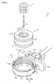
FIG. 2 is an exploded perspective view illustrating the configuration of a torque detection device of the electric power steering system according to the embodiment; -
FIG. 3A is an exploded perspective view of a first magnetism collection holder of the torque detection device; -
FIG. 3B is an exploded perspective view of a second magnetism collection holder of the torque detection device; -
FIG. 4 is a top view of the second magnetism collection holder of the torque detection device; -
FIG. 5 is a bottom view of the second magnetism collection holder of the torque detection device; -
FIG. 6 is a perspective view of a lid portion attached to the bottom surface of the second magnetism collection holder of the torque detection device; -
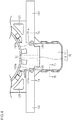
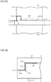
FIG. 7A is a schematic sectional view taken along theline 7a-7a inFIG. 4 , illustrating a path for intrusion of water into the torque detection device; and -
FIG. 7B is a schematic sectional view taken along theline 7b-7b inFIG. 4 , illustrating a path for intrusion of water into the torque detection device. - An embodiment in which a torque detection device according to the present invention is applied to an electric power steering system (hereinafter referred to as an "EPS") will be described below. As illustrated in
FIG. 1 , the EPS 1 includes a steering mechanism 2 that steers steeredwheels 18 on the basis of an operation of asteering wheel 10 performed by a driver, anassist mechanism 3 that assists the driver in performing a steering operation, and an electronic control unit (ECU) 40 that controls theassist mechanism 3. - The steering mechanism 2 includes the
steering wheel 10 and asteering shaft 11 that rotates together with thesteering wheel 10. Thesteering shaft 11 has acolumn shaft 12 coupled to thesteering wheel 10, anintermediate shaft 13 coupled to the lower end portion of thecolumn shaft 12, and apinion shaft 14 coupled to the lower end portion of theintermediate shaft 13. The lower end portion of thepinion shaft 14 is coupled to arack shaft 15, which serves as a steered shaft, via a rack-and-pinion mechanism 16. Thus, in the steering mechanism 2, rotational motion of thesteering shaft 11 is converted into reciprocal linear motion in the axial direction of the rack shaft 15 (the right-left direction inFIG. 1 ) via the rack-and-pinion mechanism 16 which is composed of a pinion gear provided at the distal end of thepinion shaft 14 and a rack provided on therack shaft 15. The reciprocal linear motion is transferred to the right and left steeredwheels 18 viatie rods 17 coupled to both ends of therack shaft 15 to vary the steered angle of the steeredwheels 18 to change the advancing direction of the vehicle. - The
assist mechanism 3 includes amotor 20 that applies an assist force to thesteering shaft 11. Arotary shaft 21 of themotor 20 is coupled to thecolumn shaft 12 via aspeed reduction mechanism 22. Thespeed reduction mechanism 22 reduces the speed of rotation of themotor 20, and transfers a rotational force at the reduced speed to thecolumn shaft 12. That is, a rotational force (motor torque) of themotor 20 is applied to thesteering shaft 11 as an assist force to assist the driver in performing a steering operation. Examples of themotor 20 include a three-phase brushless motor that is rotated on the basis of drive electric power with three phases (U-, V-, and W-phases). - The
ECU 40 controls themotor 20 on the basis of the results of detection performed by various sensors provided in the vehicle. Examples of the various sensors include atorque sensor 30 that serves as the torque detection device, and arotational angle sensor 31. Thetorque sensor 30 is provided to thecolumn shaft 12. Therotational angle sensor 31 is provided to themotor 20. Thecolumn shaft 12 is constituted of aninput shaft 12a on thesteering wheel 10 side and anoutput shaft 12b on theintermediate shaft 13 side. Theinput shaft 12a and theoutput shaft 12b are coupled to each other by atorsion bar 19. Thetorsion bar 19 is deformed to be warped when an operation of thesteering wheel 10 is transferred to theoutput shaft 12b via theinput shaft 12a. Thetorque sensor 30 detects steering torque Th applied to the steeringshaft 11 on the basis of a warp in thetorsion bar 19 caused along with a steering operation performed by the driver. Therotational angle sensor 31 detects a rotational angle θm of therotary shaft 21. TheECU 40 sets a target assist force on the basis of outputs from the sensors, and controls a current supplied to themotor 20 such that the actual assist force becomes the target assist force. - The torque sensor 30 (torque detection device) will be described in detail. As illustrated in
FIG. 2 , thetorque sensor 30 has thetorsion bar 19, apermanent magnet 50 coupled to theinput shaft 12a, acylindrical yoke 60 coupled to theoutput shaft 12b, and a tubularmagnetism collection unit 70 disposed so as to cover the periphery of theyoke 60. - The
yoke 60 is disposed coaxially with theoutput shaft 12b. Theyoke 60 is provided around thepermanent magnet 50 with a certain clearance therefrom. Theyoke 60 includes twomagnetic yokes 60a and 60b. Themagnetic yokes 60a and 60b each include lugs 61 a in an isosceles triangle shape provided at equal intervals in the circumferential direction to extend in a direction that is perpendicular to a flat surface of a plate-shapedannular portion 61. Thelugs 61a are molded in asynthetic resin body 62 with therespective lugs 61 a facing each other in the axial direction as displaced at certain intervals in the circumferential direction. Surfaces of themagnetic yokes 60a and 60b that face thepermanent magnet 50 are exposed from thesynthetic resin body 62. - In a neutral state in which torque is not applied to the
input shaft 12a, the distal ends of therespective lugs 61 a of themagnetic yokes 60a and 60b point toward the boundaries between the N poles and the S poles of thepermanent magnet 50. - The
magnetism collection unit 70 includes: two magnetism collection rings 71a and 71b that guide magnetic flux from themagnetic yokes 60a and 60b, respectively; first and secondmagnetism collection holders magnetic shield 80 that covers the outer peripheries of the magnetism collection rings 71a and 71b. The firstmagnetism collection holder 72a and the secondmagnetism collection holder 72b constitute amagnetism collection holder 72. That is, themagnetism collection holder 72 is constituted by assembling the firstmagnetism collection holder 72a and the secondmagnetism collection holder 72b which are adjacent to each other in the axial direction. - As illustrated in
FIG. 3A , the firstmagnetism collection holder 72a has an annularfirst ring portion 73 and a rectangular plate-shapedsubstrate housing portion 74 integrally coupled to the outer peripheral surface of thefirst ring portion 73 to project radially outward. A plurality of (four) recessedportions 78 are provided in the inner peripheral surface of thefirst ring portion 73 of the firstmagnetism collection holder 72a. The firstmagnetism collection holder 72a is made of a synthetic resin, for example. - As illustrated in
FIG. 2 , the magnetism collection ring 71 a is held on the inner peripheral surface of thefirst ring portion 73, and the inner peripheral surface of thefirst ring portion 73 faces the outer peripheral surface of theyoke 60 via a clearance in the radial direction. The magnetic yoke 60a and the magnetism collection ring 71a face each other via a clearance in the radial direction. In addition, themagnetic yoke 60b and themagnetism collection ring 71b face each other via a clearance in the radial direction. - A plurality of
flange portions 73a that project radially outward are provided on an end surface of thefirst ring portion 73 on the opposite side of the secondmagnetism collection holder 72b. As illustrated inFIG. 3B , the secondmagnetism collection holder 72b has an annularsecond ring portion 75 and a rectangular plate-shapedsubstrate housing portion 76 integrally coupled to the outer peripheral surface of thesecond ring portion 75 to project radially outward. The secondmagnetism collection holder 72b is made of a synthetic resin, for example. A substrate provided withHall ICs 90 is disposed in thesubstrate housing portion 76. The inside diameter and the outside diameter of thesecond ring portion 75 are the same as the inside diameter and the outside diameter, respectively, of thefirst ring portion 73 of the firstmagnetism collection holder 72a. As illustrated inFIG. 2 , themagnetism collection ring 71b is held on the inner peripheral surface of thesecond ring portion 75. The magnetic yoke 60a and themagnetism collection ring 71b are disposed so as to face each other via a clearance in the radial direction. In addition, themagnetic yoke 60b and themagnetism collection ring 71b are disposed so as to face each other via a clearance in the radial direction. - As illustrated in
FIG. 3B , a plurality of (four)engagement protrusions 77 that project toward the firstmagnetism collection holder 72a are provided on the outer peripheral surface of thesecond ring portion 75 of the secondmagnetism collection holder 72b. Engagement lugs provided at the distal ends of theengagement protrusions 77 are inserted into the plurality of recessedportions 78 to be engaged with an end surface of thefirst ring portion 73 of the firstmagnetism collection holder 72a in the axial direction. The secondmagnetism collection holder 72b is disposed coaxially with the firstmagnetism collection holder 72a with the engagement lugs of theengagement protrusions 77 engaged with thefirst ring portion 73. In addition,flange portions 75a that project radially outward are provided on the outer peripheral edge portion of an end portion of thesecond ring portion 75 on the opposite side of the firstmagnetism collection holder 72a. - The magnetism collection ring 71a and the
magnetism collection ring 71b face each other. TheHall ICs 90 which are disposed in thesubstrate housing portion 76 are covered by thesubstrate housing portion 74 with thesubstrate housing portion 74 assembled to thesubstrate housing portion 76. TheHall ICs 90 are connected to theECU 40, which is external, via a cord 91 (seeFIG. 1 ). - As illustrated in
FIG. 2 , themagnetic shield 80 is fitted with the outer peripheral surface of thefirst ring portion 73 and the outer peripheral surface of thesecond ring portion 75. A material that can block magnetism such as metal, for example, is adopted as the material of themagnetic shield 80. Themagnetic shield 80 is provided as curved in a C-shape in cross section. In addition, the length of themagnetic shield 80 in the axial direction is slightly larger than the total of the respective lengths of thefirst ring portion 73 and thesecond ring portion 75 in the axial direction. When theengagement protrusions 77 are engaged with an end portion of thefirst ring portion 73 in the axial direction, both end portions of themagnetic shield 80 in the axial direction abut against theflange portions 73a of thefirst ring portion 73 and theflange portions 75a of thesecond ring portion 75 in the axial direction. Themagnetic shield 80 is fixed to the firstmagnetism collection holder 72a and the secondmagnetism collection holder 72b. - As illustrated in
FIG. 3B , a pair offlanges substrate housing portion 76 in a direction that is orthogonal to the direction in which thesubstrate housing portion 76 extends from the secondmagnetism collection holder 72b. Theflanges flanges substrate housing portion 74. In the stacking direction, the length of theflanges substrate housing portion 76. Theflanges flat plate portion 111 of thesubstrate housing portion 76.Guide grooves flanges guide grooves substrate housing portion 74 and thesubstrate housing portion 76. - As illustrated in
FIGS. 2 and3A , a plate-shapedpartition wall 102 that extends along the stacking direction of thesubstrate housing portion 74 and thesubstrate housing portion 76 is provided on a surface of thesubstrate housing portion 74 on the opposite side of thesubstrate housing portion 76.Flange portions 103 that project laterally are provided on portions of both side surfaces of thepartition wall 102 on thefirst ring portion 73 side. Portions of both side surfaces of thepartition wall 102 that are not provided with theflange portions 103 are flush with both side surfaces of thesubstrate housing portion 74. Theflange portions 103 of thepartition wall 102 are fitted with theguide grooves flanges portion 104 as a concavo-convex shape notched into a rectangular shape is provided in a surface of thesubstrate housing portion 74 on the opposite side of thepartition wall 102. For example, the recessedportion 104 corresponds to thepartition wall 102 in the stacking direction of thesubstrate housing portion 74 and thesubstrate housing portion 76. As illustrated inFIG. 3B , asubstrate arrangement portion 110, which is a portion of thesubstrate housing portion 76 in which theHall ICs 90 are disposed, is formed so as to be lower than theflat plate portion 111, which is the other portion of thesubstrate housing portion 76. - As illustrated in
FIGS. 3B and4 , thesubstrate arrangement portion 110 is provided withpartitioning portions flat plate portion 111 toward thesecond ring portion 75. Anextended portion 105a is provided at the distal end of thepartitioning portion 105. Theextended portion 105a is positioned in correspondence with a portion of theflange 100 on thesecond ring portion 75 side with respect to a portion of theflange 100 provided with theguide groove 100a. Theextended portion 105a extends toward thesecond ring portion 75 with respect to a portion of theflange 100 provided with theguide groove 100a in a direction that is orthogonal to the direction in which thepartitioning portion 105 extends. Theextended portion 105a contacts a portion of theflange 100 on thesecond ring portion 75 side with respect to a portion of theflange 100 provided with theguide groove 100a. Meanwhile, thepartitioning portion 105 does not contact a portion of theflange 100 on the opposite side of thesecond ring portion 75 with respect to a portion of theflange 100 provided with theguide groove 100a. Similarly to thepartitioning portion 105, thepartitioning portion 106 is provided with an extended portion 106a at the distal end of thepartitioning portion 106. The extended portion 106a is positioned in correspondence with a portion of theflange 101 on thesecond ring portion 75 side with respect to a portion of theflange 101 provided with theguide groove 101a. - When the
substrate housing portion 74 and thesubstrate housing portion 76 are stacked on each other, theflange portions 103 of thepartition wall 102 are fitted with theguide grooves magnetism collection holder 72a and the secondmagnetism collection holder 72b. When thesubstrate housing portion 74 and thesubstrate housing portion 76 are stacked on each other, in addition, theextended portions 105a and 106a are fitted with the recessedportion 104. Thepartitioning portions extended portions 105a and 106a of are concavo-convex shapes of thesubstrate housing portions - A stepped
portion 107 is provided at the peripheral edge portion of theflat plate portion 111. The steppedportion 107 is provided at a lower position than theflat plate portion 111. When thesubstrate housing portion 74 and thesubstrate housing portion 76 are stacked on each other, the steppedportion 107 is fitted with aperipheral wall portion 74a provided at the peripheral edge portion of thesubstrate housing portion 74. That is, the upper surface of thesubstrate housing portion 76 is covered by thesubstrate housing portion 74 with theperipheral wall portion 74a disposed along the steppedportion 107. - As illustrated in
FIG. 4 , the secondmagnetism collection holder 72b is provided withtriangular reservoir portions second ring portion 75 and theflanges - As illustrated in
FIG. 5 , a hollowfitting portion 108 is provided in the bottom surface of thesubstrate housing portion 76 on the opposite side of thesubstrate housing portion 74. Thefitting portion 108 is provided to facilitate the work of fixing theHall ICs 90 when attaching theHall ICs 90 etc. - As illustrated in
FIGS. 5 and 6 , alid portion 130 with a bottom surface in a flat plate shape is attached to the bottom surface of thesubstrate housing portion 76. Thelid portion 130 has abottom wall portion 131. The contour shape of thebottom wall portion 131 corresponds to the bottom surface shape of thesubstrate housing portion 76. Areservoir portion 132 in a rectangular parallelepiped shape is provided on a surface of thebottom wall portion 131 of thelid portion 130 that faces thefitting portion 108. Thereservoir portion 132 is provided so as to project from thebottom wall portion 131, and the center portion of thereservoir portion 132 is recessed toward thebottom wall portion 131. In addition, thelid portion 130 is provided with fourengagement protrusions 133. The firstmagnetism collection holder 72a and the secondmagnetism collection holder 72b are held by thebottom wall portion 131 and the engagement protrusions 133 (lug portions at the distal ends) of the lid portion 130 (seeFIG. 2 ) with the firstmagnetism collection holder 72a (substrate housing portion 74) and the secondmagnetism collection holder 72b (substrate housing portion 76) stacked on each other. Consequently, the firstmagnetism collection holder 72a and the secondmagnetism collection holder 72b are assembled to each other. - The function and the effect of the embodiment will be described. Foreign matter such as water that has intruded into the EPS 1 may adhere to the outer surface of the
torque sensor 30. If water intrudes into the firstmagnetism collection holder 72a and the secondmagnetism collection holder 72b of thetorque sensor 30 to contact theHall ICs 90, an abnormality may be caused in theHall ICs 90. - In order for water to make its way to the
Hall ICs 90, it is necessary for the water to intrude along surfaces on which thesubstrate housing portion 74 and thesubstrate housing portion 76 are stacked on each other along a path indicated by the arrow C1 ofFIG. 7A and a path indicated by the arrow C2 ofFIG. 7B . - Specifically, as illustrated in
FIGS. 7A and4 , water that intrudes along the path indicated by the arrow C1 intrudes into a gap between theperipheral wall portion 74a of thesubstrate housing portion 74 and the steppedportion 107 of thesubstrate housing portion 76 from the outside of thesubstrate housing portion 74 and thesubstrate housing portion 76. Then, the water that has intruded makes its way to the vicinity of thepartitioning portions extended portions 105a and 106a. Thepartitioning portions extended portions 105a and 106a are provided at a higher position than the substrate arrangement portion 110 (in a projecting manner). Therefore, it is necessary for the water that has intruded to climb over the partitioningportions extended portions 105a and 106a in order to make its way to theHall ICs 90. In this event, it is necessary for the water that has intruded from the outside to intrude via corner portions V1 and V2, which accordingly makes it difficult for such water to intrude into themagnetism collection holder 72. The corner portions V1 and V2 form a cranked path. The corner portions V1 and V2 form a type of a labyrinth structure. - Meanwhile, as illustrated in
FIG. 7B , water that intrudes along the path indicated by the arrow C2 intrudes into a gap between theperipheral wall portion 74a of thesubstrate housing portion 74 and the steppedportion 107 of thesubstrate housing portion 76 from the outside of thesubstrate housing portion 74 and thesubstrate housing portion 76. Then, the water would intrude into a gap between theflat plate portion 111 and the bottom surface of the substrate housing portion 74 (a surface on thesubstrate housing portion 76 side) via two corner portions V3 and V4 formed between theperipheral wall portion 74a of thesubstrate housing portion 74 and the steppedportion 107 of thesubstrate housing portion 76 to make its way to theHall ICs 90 in thesubstrate arrangement portion 110. However, it is necessary for water that has intruded from the outside to intrude via the two corner portions V3 and V4 which are formed between theperipheral wall portion 74a of thesubstrate housing portion 74 and the steppedportion 107 of thesubstrate housing portion 76, which accordingly makes it difficult for such water to intrude into themagnetism collection holder 72. Intrusion of water into themagnetism collection holder 72 is suppressed also by the fact that the path for intrusion to thesubstrate arrangement portion 110 from the outside of thesubstrate housing portion 74 and thesubstrate housing portion 76 is elongated by providing the corner portions V3 and V4. The corner portions V3 and V4 form a type of a labyrinth structure. - Even if water would intrude through a gap between the
guide grooves flanges partition wall 102, it is necessary for the water to climb over the two corner portions V3 and V4 which are provided between theguide grooves flanges partition wall 102. Therefore, it is difficult for such water to intrude into themagnetism collection holder 72. - The
fitting portion 108 is filled with thereservoir portion 132 by attaching thelid portion 130 to the bottom surface of thesubstrate housing portion 76. Thus, intrusion of water from thefitting portion 108 is suppressed. This is because, in the case where water makes its way to theHall ICs 90 through a gap between thesubstrate housing portion 76 and thelid portion 130, the corner portions which are formed between thesubstrate housing portion 76 and thereservoir portion 132 of thelid portion 130 makes it necessary for the water which has intruded to progress against the direction of the gravitational force. When thetorque sensor 30 is mounted on the EPS 1, thesubstrate housing portion 76 is positioned on the lower side of thesubstrate housing portion 74 in the direction of the gravitational force. The water that has intruded can be stored in thereservoir portion 132 by providing thelid portion 130 with thereservoir portion 132. Therefore, it is possible to suppress such water reaching theHall ICs 90. - The concavo-convex shape which is formed by the
flange portion 103 and theguide grooves partition wall 102 and theflanges - Water that has intruded into the
magnetism collection holder 72 is stored in thereservoir portions magnetism collection holder 72b. Consequently, it is possible to suppress water reaching theHall ICs 90. For example, if water does not make its way to theHall ICs 90 but moves to thereservoir portion 120 as indicated by the arrow C3 (seeFIG. 4 ) even in the case where water has intruded into thesubstrate arrangement portion 110, the recess of thereservoir portion 120 suppresses water making its way to theHall ICs 90 thereafter. - The embodiment may be modified as follows. The following other embodiments may be combined with each other as long as the embodiments do not technically contradict with each other. In the embodiment, the
Hall ICs 90 are adopted as elements that detect torque. However, the embodiment is not limited thereto. For example, ICs that include elements that detect magnetism such as magnetoresistance effect elements and magnetoimpedance elements may be adopted as elements that detect torque. - In the embodiment, the two corner portions V3 and V4 which are formed between the
peripheral wall portion 74a of thesubstrate housing portion 74 and the steppedportion 107 of thesubstrate housing portion 76 suppress intrusion of water into themagnetism collection holder 72. However, the embodiment is not limited thereto. Three or more corner portions V3 and V4 may be provided. - In the embodiment, the two corner portions V1 and V2 which are formed by the
partitioning portions extended portions 105a and 106a suppress intrusion of water into themagnetism collection holder 72. However, the embodiment is not limited thereto. Three or more corner portions V1 and V2 may be provided. - In the description, intrusion of water into the
magnetism collection holder 72 is suppressed. However, the embodiment is not limited thereto. Intrusion of foreign matter such as dust is also suppressed. In the embodiment, the corner portions V1 and V2 and the corner portions V3 and V4 are provided. However, only the corner portions V1 and V2 or the corner portions V3 and V4 may be provided. - In the embodiment, the
substrate housing portion 76 of the secondmagnetism collection holder 72b is provided with thefitting portion 108. However, thesubstrate housing portion 76 may not be provided with thefitting portion 108. That is, the bottom surface of thesubstrate housing portion 76 on the opposite side of thesubstrate housing portion 74 may be filled in advance. In this case, thelid portion 130 may not be provided. - The
torque sensor 30 may be applied not only to the EPS 1 which assists linear motion of therack shaft 15, which is caused in conjunction with a steering operation, utilizing the rotational force of themotor 20, but also to a steer-by-wire (SBW) system. In addition, thetorque sensor 30 may be implemented not only as atorque sensor 30 for a front-wheel steering system, but also as atorque sensor 30 for a rear-wheel steering system or a four-wheel steering (4WS) system.
Claims (7)
- A torque detection device comprising:a permanent magnet;a magnetic yoke which is disposed in a magnetic field formed by the permanent magnet and a position of which relative to the permanent magnet is variable;a tubular magnetism collection unit that has a tubular magnetism collection holder and a magnetism collection ring, the magnetism collection holder being formed so as to surround the magnetic yoke and composed of a first magnetism collection holder and a second magnetism collection holder, which are adjacent to each other in an axial direction, assembled to each other, and the magnetism collection ring being attached to an inner peripheral surface of the magnetism collection holder to collect magnetic flux of the magnetic yoke; anda magnetic sensor that detects magnetic flux generated in a magnetic circuit formed by the permanent magnet, the magnetic yoke, and the magnetism collection ring, wherein:the first magnetism collection holder and the second magnetism collection holder have respective substrate housing portions that project in a radial direction to house the magnetic sensor; anda concavo-convex shape on a side of the substrate housing portion of the first magnetism collection holder and a concavo-convex shape on a side of the substrate housing portion of the second magnetism collection holder are formed on respective mating surfaces of the substrate housing portion of the first magnetism collection holder and the substrate housing portion of the second magnetism collection holder to be fitted with each other.
- The torque detection device according to claim 1, wherein
the concavo-convex shape of the substrate housing portion of the first magnetism collection holder and the concavo-convex shape of the substrate housing portion of the second magnetism collection holder are provided with a plurality of steps. - The torque detection device according to claim 1 or 2, wherein
the concavo-convex shapes have a portion that extends along a mating direction of the first magnetism collection holder and the second magnetism collection holder. - The torque detection device according to any one of claims 1 to 3, wherein:a pair of flanges are provided on both side surfaces of the substrate housing portion of the second magnetism collection holder;the pair of flanges face each other;a partition wall to be attached between the pair of flanges is provided on a surface of the substrate housing portion of the first magnetism collection holder on a opposite side of the second magnetism collection holder;a portion of the substrate housing portion of the second magnetism collection holder on the opposite side of the magnetism collection ring from a portion in which the magnetic sensor is disposed is provided with a partitioning portion that projects in a mating direction of the mating surfaces with respect to a portion of the substrate housing portion of the second magnetism collection holder in which the magnetic sensor is disposed, the partitioning portion serving as a part of the concavo-convex shape of the second magnetism collection holder;the substrate housing portion of the first magnetism collection holder is provided with a recessed portion corresponding to the partitioning portion and serving as a part of the concavo-convex shape of the first magnetism collection holder; andthe recessed portion is fitted with the partitioning portion with the partition wall attached between the pair of flanges.
- The torque detection device according to any one of claims 1 to 4, wherein:a peripheral edge portion of the substrate housing portion of the second magnetism collection holder is provided with a stepped portion that serves as a part of the concavo-convex shape of the second magnetism collection holder; anda peripheral edge portion of the substrate housing portion of the first magnetism collection holder is provided with a peripheral wall portion that serves as a part of the concavo-convex shape of the first magnetism collection holder to be fitted with the stepped portion.
- The torque detection device according to any one of claims 1 to 5, wherein:a hollow fitting portion is provided in an end surface of the second magnetism collection holder on the opposite side of the first magnetism collection holder; anda lid portion is attached to the second magnetism collection holder with the fitting portion fitted with a reservoir portion that projects toward the fitting portion along the mating direction of the mating surfaces, one surface of the reservoir portion being opened.
- An electric power steering system comprising:the torque detection device according to any one of claims 1 to 6.
Applications Claiming Priority (1)
| Application Number | Priority Date | Filing Date | Title |
|---|---|---|---|
| JP2016147771A JP6729135B2 (en) | 2016-07-27 | 2016-07-27 | Torque detection device and electric power steering device |
Publications (1)
| Publication Number | Publication Date |
|---|---|
| EP3276318A1 true EP3276318A1 (en) | 2018-01-31 |
Family
ID=59409187
Family Applications (1)
| Application Number | Title | Priority Date | Filing Date |
|---|---|---|---|
| EP17182856.9A Ceased EP3276318A1 (en) | 2016-07-27 | 2017-07-24 | Torque detection device and electric power steering system |
Country Status (5)
| Country | Link |
|---|---|
| US (1) | US10683032B2 (en) |
| EP (1) | EP3276318A1 (en) |
| JP (1) | JP6729135B2 (en) |
| CN (1) | CN107662635B (en) |
| DE (1) | DE202017007168U1 (en) |
Cited By (2)
| Publication number | Priority date | Publication date | Assignee | Title |
|---|---|---|---|---|
| WO2020120452A1 (en) | 2018-12-11 | 2020-06-18 | Thyssenkrupp Presta Ag | Magnetic shielding of a torque sensor for an electromechanical power steering system in a motor vehicle |
| WO2020178078A1 (en) | 2019-03-01 | 2020-09-10 | Thyssenkrupp Presta Ag | Torque sensor unit comprising a magnetic shield |
Families Citing this family (4)
| Publication number | Priority date | Publication date | Assignee | Title |
|---|---|---|---|---|
| JP7115113B2 (en) * | 2018-07-27 | 2022-08-09 | 株式会社ジェイテクト | sensor device |
| JP7124566B2 (en) * | 2018-08-29 | 2022-08-24 | 株式会社ジェイテクト | sensor device |
| KR102106294B1 (en) * | 2018-09-21 | 2020-05-04 | 주식회사 만도 | Vehicle Steering Apparatus |
| KR20240103429A (en) * | 2022-12-27 | 2024-07-04 | 엘지이노텍 주식회사 | Apparatus for sensing |
Citations (2)
| Publication number | Priority date | Publication date | Assignee | Title |
|---|---|---|---|---|
| WO2011048846A1 (en) * | 2009-10-20 | 2011-04-28 | 株式会社ホンダロック | Torque sensor |
| EP2833110A1 (en) * | 2013-08-02 | 2015-02-04 | Jtekt Corporation | Torque detecting device and electric power steering system |
Family Cites Families (5)
| Publication number | Priority date | Publication date | Assignee | Title |
|---|---|---|---|---|
| JP3954693B2 (en) * | 1997-07-14 | 2007-08-08 | 本田技研工業株式会社 | Input torque detection device for an electric auxiliary vehicle |
| JP3980716B2 (en) * | 1997-10-07 | 2007-09-26 | 本田技研工業株式会社 | Bicycle with auxiliary power |
| JP4794262B2 (en) * | 2005-09-30 | 2011-10-19 | 株式会社ジェイテクト | Torque detection device and electric power steering device using the same |
| KR101034113B1 (en) * | 2009-03-20 | 2011-05-13 | 대성전기공업 주식회사 | Non-contact Torque Sensor for Steering System |
| CN203606051U (en) * | 2013-11-13 | 2014-05-21 | 重庆长风机器有限责任公司 | Electromagnetic torque sensor in electric power steering system |
-
2016
- 2016-07-27 JP JP2016147771A patent/JP6729135B2/en active Active
-
2017
- 2017-07-19 US US15/653,839 patent/US10683032B2/en active Active
- 2017-07-21 CN CN201710599597.XA patent/CN107662635B/en active Active
- 2017-07-24 DE DE202017007168.1U patent/DE202017007168U1/en active Active
- 2017-07-24 EP EP17182856.9A patent/EP3276318A1/en not_active Ceased
Patent Citations (3)
| Publication number | Priority date | Publication date | Assignee | Title |
|---|---|---|---|---|
| WO2011048846A1 (en) * | 2009-10-20 | 2011-04-28 | 株式会社ホンダロック | Torque sensor |
| EP2833110A1 (en) * | 2013-08-02 | 2015-02-04 | Jtekt Corporation | Torque detecting device and electric power steering system |
| JP2015031600A (en) | 2013-08-02 | 2015-02-16 | 株式会社ジェイテクト | Torque detection device and electric power steering device |
Cited By (4)
| Publication number | Priority date | Publication date | Assignee | Title |
|---|---|---|---|---|
| WO2020120452A1 (en) | 2018-12-11 | 2020-06-18 | Thyssenkrupp Presta Ag | Magnetic shielding of a torque sensor for an electromechanical power steering system in a motor vehicle |
| DE102018131712A1 (en) | 2018-12-11 | 2020-06-18 | Thyssenkrupp Ag | Magnetic shielding of a torque sensor for an electromechanical power steering system of a motor vehicle |
| WO2020178078A1 (en) | 2019-03-01 | 2020-09-10 | Thyssenkrupp Presta Ag | Torque sensor unit comprising a magnetic shield |
| US12072258B2 (en) | 2019-03-01 | 2024-08-27 | Thyssenkrupp Presta Ag | Torque sensor unit comprising a magnetic shield |
Also Published As
| Publication number | Publication date |
|---|---|
| JP6729135B2 (en) | 2020-07-22 |
| DE202017007168U1 (en) | 2019-11-13 |
| US10683032B2 (en) | 2020-06-16 |
| US20180029638A1 (en) | 2018-02-01 |
| JP2018017596A (en) | 2018-02-01 |
| CN107662635A (en) | 2018-02-06 |
| CN107662635B (en) | 2021-08-17 |
Similar Documents
| Publication | Publication Date | Title |
|---|---|---|
| EP3276317B1 (en) | Torque detection device and electric power steering system | |
| US10683032B2 (en) | Torque detection device and electric power steering system | |
| EP2833110B1 (en) | Torque detecting device and electric power steering system | |
| US9302700B2 (en) | Torque sensor and power steering system using the torque sensor | |
| US9505431B2 (en) | Rotation detection device and power steering device | |
| US9004221B2 (en) | Torque sensor and power steering system using the torque sensor | |
| US10404142B2 (en) | Motor control apparatus and power steering apparatus | |
| JP5130097B2 (en) | Torque sensor | |
| US10794781B2 (en) | Sensor device | |
| EP3715221B1 (en) | Sensor device | |
| US9121784B2 (en) | Torque detector and electric power steering system including the torque detector | |
| JP6670230B2 (en) | Torque detector | |
| JP6726593B2 (en) | Torque sensor | |
| US12491927B2 (en) | Steer by wire type steering apparatus | |
| EP3734812B1 (en) | Motor | |
| JP2018047726A (en) | Steering device | |
| JP6753196B2 (en) | Insert molding method, insert molded product, torque detector, and electric power steering device | |
| JP6680130B2 (en) | Torque detection device and electric power steering device | |
| JP2019200135A (en) | Torque detection device and electrically-driven power steering device | |
| US9945742B2 (en) | Torque sensor and electric power steering apparatus | |
| JP2018131092A (en) | Electric power steering device | |
| JP2018059740A (en) | Torque sensor |
Legal Events
| Date | Code | Title | Description |
|---|---|---|---|
| PUAI | Public reference made under article 153(3) epc to a published international application that has entered the european phase |
Free format text: ORIGINAL CODE: 0009012 |
|
| AK | Designated contracting states |
Kind code of ref document: A1 Designated state(s): AL AT BE BG CH CY CZ DE DK EE ES FI FR GB GR HR HU IE IS IT LI LT LU LV MC MK MT NL NO PL PT RO RS SE SI SK SM TR |
|
| AX | Request for extension of the european patent |
Extension state: BA ME |
|
| 17P | Request for examination filed |
Effective date: 20180724 |
|
| RBV | Designated contracting states (corrected) |
Designated state(s): AL AT BE BG CH CY CZ DE DK EE ES FI FR GB GR HR HU IE IS IT LI LT LU LV MC MK MT NL NO PL PT RO RS SE SI SK SM TR |
|
| 17Q | First examination report despatched |
Effective date: 20181024 |
|
| STAA | Information on the status of an ep patent application or granted ep patent |
Free format text: STATUS: THE APPLICATION HAS BEEN REFUSED |
|
| 18R | Application refused |
Effective date: 20190808 |