EP3276245B1 - Eine membrangasbehälterkuppel mit reduziertem wärmeverlust - Google Patents
Eine membrangasbehälterkuppel mit reduziertem wärmeverlust Download PDFInfo
- Publication number
- EP3276245B1 EP3276245B1 EP17182451.9A EP17182451A EP3276245B1 EP 3276245 B1 EP3276245 B1 EP 3276245B1 EP 17182451 A EP17182451 A EP 17182451A EP 3276245 B1 EP3276245 B1 EP 3276245B1
- Authority
- EP
- European Patent Office
- Prior art keywords
- membrane
- gas holder
- gas
- holder dome
- metal foil
- Prior art date
- Legal status (The legal status is an assumption and is not a legal conclusion. Google has not performed a legal analysis and makes no representation as to the accuracy of the status listed.)
- Active
Links
Images


Classifications
-
- F—MECHANICAL ENGINEERING; LIGHTING; HEATING; WEAPONS; BLASTING
- F17—STORING OR DISTRIBUTING GASES OR LIQUIDS
- F17C—VESSELS FOR CONTAINING OR STORING COMPRESSED, LIQUEFIED OR SOLIDIFIED GASES; FIXED-CAPACITY GAS-HOLDERS; FILLING VESSELS WITH, OR DISCHARGING FROM VESSELS, COMPRESSED, LIQUEFIED, OR SOLIDIFIED GASES
- F17C3/00—Vessels not under pressure
- F17C3/02—Vessels not under pressure with provision for thermal insulation
- F17C3/022—Land-based bulk storage containers
-
- F—MECHANICAL ENGINEERING; LIGHTING; HEATING; WEAPONS; BLASTING
- F17—STORING OR DISTRIBUTING GASES OR LIQUIDS
- F17C—VESSELS FOR CONTAINING OR STORING COMPRESSED, LIQUEFIED OR SOLIDIFIED GASES; FIXED-CAPACITY GAS-HOLDERS; FILLING VESSELS WITH, OR DISCHARGING FROM VESSELS, COMPRESSED, LIQUEFIED, OR SOLIDIFIED GASES
- F17C2201/00—Vessel construction, in particular geometry, arrangement or size
- F17C2201/01—Shape
- F17C2201/0104—Shape cylindrical
- F17C2201/0109—Shape cylindrical with exteriorly curved end-piece
-
- F—MECHANICAL ENGINEERING; LIGHTING; HEATING; WEAPONS; BLASTING
- F17—STORING OR DISTRIBUTING GASES OR LIQUIDS
- F17C—VESSELS FOR CONTAINING OR STORING COMPRESSED, LIQUEFIED OR SOLIDIFIED GASES; FIXED-CAPACITY GAS-HOLDERS; FILLING VESSELS WITH, OR DISCHARGING FROM VESSELS, COMPRESSED, LIQUEFIED, OR SOLIDIFIED GASES
- F17C2201/00—Vessel construction, in particular geometry, arrangement or size
- F17C2201/01—Shape
- F17C2201/0176—Shape variable
- F17C2201/018—Shape variable with bladders
-
- F—MECHANICAL ENGINEERING; LIGHTING; HEATING; WEAPONS; BLASTING
- F17—STORING OR DISTRIBUTING GASES OR LIQUIDS
- F17C—VESSELS FOR CONTAINING OR STORING COMPRESSED, LIQUEFIED OR SOLIDIFIED GASES; FIXED-CAPACITY GAS-HOLDERS; FILLING VESSELS WITH, OR DISCHARGING FROM VESSELS, COMPRESSED, LIQUEFIED, OR SOLIDIFIED GASES
- F17C2201/00—Vessel construction, in particular geometry, arrangement or size
- F17C2201/01—Shape
- F17C2201/0176—Shape variable
- F17C2201/0185—Shape variable with separating membrane
-
- F—MECHANICAL ENGINEERING; LIGHTING; HEATING; WEAPONS; BLASTING
- F17—STORING OR DISTRIBUTING GASES OR LIQUIDS
- F17C—VESSELS FOR CONTAINING OR STORING COMPRESSED, LIQUEFIED OR SOLIDIFIED GASES; FIXED-CAPACITY GAS-HOLDERS; FILLING VESSELS WITH, OR DISCHARGING FROM VESSELS, COMPRESSED, LIQUEFIED, OR SOLIDIFIED GASES
- F17C2201/00—Vessel construction, in particular geometry, arrangement or size
- F17C2201/03—Orientation
- F17C2201/032—Orientation with substantially vertical main axis
-
- F—MECHANICAL ENGINEERING; LIGHTING; HEATING; WEAPONS; BLASTING
- F17—STORING OR DISTRIBUTING GASES OR LIQUIDS
- F17C—VESSELS FOR CONTAINING OR STORING COMPRESSED, LIQUEFIED OR SOLIDIFIED GASES; FIXED-CAPACITY GAS-HOLDERS; FILLING VESSELS WITH, OR DISCHARGING FROM VESSELS, COMPRESSED, LIQUEFIED, OR SOLIDIFIED GASES
- F17C2201/00—Vessel construction, in particular geometry, arrangement or size
- F17C2201/05—Size
- F17C2201/052—Size large (>1000 m3)
-
- F—MECHANICAL ENGINEERING; LIGHTING; HEATING; WEAPONS; BLASTING
- F17—STORING OR DISTRIBUTING GASES OR LIQUIDS
- F17C—VESSELS FOR CONTAINING OR STORING COMPRESSED, LIQUEFIED OR SOLIDIFIED GASES; FIXED-CAPACITY GAS-HOLDERS; FILLING VESSELS WITH, OR DISCHARGING FROM VESSELS, COMPRESSED, LIQUEFIED, OR SOLIDIFIED GASES
- F17C2203/00—Vessel construction, in particular walls or details thereof
- F17C2203/03—Thermal insulations
- F17C2203/0304—Thermal insulations by solid means
- F17C2203/0308—Radiation shield
- F17C2203/032—Multi-sheet layers
-
- F—MECHANICAL ENGINEERING; LIGHTING; HEATING; WEAPONS; BLASTING
- F17—STORING OR DISTRIBUTING GASES OR LIQUIDS
- F17C—VESSELS FOR CONTAINING OR STORING COMPRESSED, LIQUEFIED OR SOLIDIFIED GASES; FIXED-CAPACITY GAS-HOLDERS; FILLING VESSELS WITH, OR DISCHARGING FROM VESSELS, COMPRESSED, LIQUEFIED, OR SOLIDIFIED GASES
- F17C2203/00—Vessel construction, in particular walls or details thereof
- F17C2203/06—Materials for walls or layers thereof; Properties or structures of walls or their materials
- F17C2203/0602—Wall structures; Special features thereof
- F17C2203/0612—Wall structures
- F17C2203/0614—Single wall
- F17C2203/0621—Single wall with three layers
-
- F—MECHANICAL ENGINEERING; LIGHTING; HEATING; WEAPONS; BLASTING
- F17—STORING OR DISTRIBUTING GASES OR LIQUIDS
- F17C—VESSELS FOR CONTAINING OR STORING COMPRESSED, LIQUEFIED OR SOLIDIFIED GASES; FIXED-CAPACITY GAS-HOLDERS; FILLING VESSELS WITH, OR DISCHARGING FROM VESSELS, COMPRESSED, LIQUEFIED, OR SOLIDIFIED GASES
- F17C2203/00—Vessel construction, in particular walls or details thereof
- F17C2203/06—Materials for walls or layers thereof; Properties or structures of walls or their materials
- F17C2203/0602—Wall structures; Special features thereof
- F17C2203/0612—Wall structures
- F17C2203/0614—Single wall
- F17C2203/0624—Single wall with four or more layers
-
- F—MECHANICAL ENGINEERING; LIGHTING; HEATING; WEAPONS; BLASTING
- F17—STORING OR DISTRIBUTING GASES OR LIQUIDS
- F17C—VESSELS FOR CONTAINING OR STORING COMPRESSED, LIQUEFIED OR SOLIDIFIED GASES; FIXED-CAPACITY GAS-HOLDERS; FILLING VESSELS WITH, OR DISCHARGING FROM VESSELS, COMPRESSED, LIQUEFIED, OR SOLIDIFIED GASES
- F17C2203/00—Vessel construction, in particular walls or details thereof
- F17C2203/06—Materials for walls or layers thereof; Properties or structures of walls or their materials
- F17C2203/0634—Materials for walls or layers thereof
- F17C2203/0658—Synthetics
- F17C2203/066—Plastics
-
- F—MECHANICAL ENGINEERING; LIGHTING; HEATING; WEAPONS; BLASTING
- F17—STORING OR DISTRIBUTING GASES OR LIQUIDS
- F17C—VESSELS FOR CONTAINING OR STORING COMPRESSED, LIQUEFIED OR SOLIDIFIED GASES; FIXED-CAPACITY GAS-HOLDERS; FILLING VESSELS WITH, OR DISCHARGING FROM VESSELS, COMPRESSED, LIQUEFIED, OR SOLIDIFIED GASES
- F17C2203/00—Vessel construction, in particular walls or details thereof
- F17C2203/06—Materials for walls or layers thereof; Properties or structures of walls or their materials
- F17C2203/068—Special properties of materials for vessel walls
- F17C2203/0685—Special properties of materials for vessel walls flexible
-
- F—MECHANICAL ENGINEERING; LIGHTING; HEATING; WEAPONS; BLASTING
- F17—STORING OR DISTRIBUTING GASES OR LIQUIDS
- F17C—VESSELS FOR CONTAINING OR STORING COMPRESSED, LIQUEFIED OR SOLIDIFIED GASES; FIXED-CAPACITY GAS-HOLDERS; FILLING VESSELS WITH, OR DISCHARGING FROM VESSELS, COMPRESSED, LIQUEFIED, OR SOLIDIFIED GASES
- F17C2203/00—Vessel construction, in particular walls or details thereof
- F17C2203/06—Materials for walls or layers thereof; Properties or structures of walls or their materials
- F17C2203/068—Special properties of materials for vessel walls
- F17C2203/0692—Special properties of materials for vessel walls transparent
-
- F—MECHANICAL ENGINEERING; LIGHTING; HEATING; WEAPONS; BLASTING
- F17—STORING OR DISTRIBUTING GASES OR LIQUIDS
- F17C—VESSELS FOR CONTAINING OR STORING COMPRESSED, LIQUEFIED OR SOLIDIFIED GASES; FIXED-CAPACITY GAS-HOLDERS; FILLING VESSELS WITH, OR DISCHARGING FROM VESSELS, COMPRESSED, LIQUEFIED, OR SOLIDIFIED GASES
- F17C2221/00—Handled fluid, in particular type of fluid
- F17C2221/03—Mixtures
- F17C2221/032—Hydrocarbons
- F17C2221/033—Methane, e.g. natural gas, CNG, LNG, GNL, GNC, PLNG
-
- F—MECHANICAL ENGINEERING; LIGHTING; HEATING; WEAPONS; BLASTING
- F17—STORING OR DISTRIBUTING GASES OR LIQUIDS
- F17C—VESSELS FOR CONTAINING OR STORING COMPRESSED, LIQUEFIED OR SOLIDIFIED GASES; FIXED-CAPACITY GAS-HOLDERS; FILLING VESSELS WITH, OR DISCHARGING FROM VESSELS, COMPRESSED, LIQUEFIED, OR SOLIDIFIED GASES
- F17C2223/00—Handled fluid before transfer, i.e. state of fluid when stored in the vessel or before transfer from the vessel
- F17C2223/01—Handled fluid before transfer, i.e. state of fluid when stored in the vessel or before transfer from the vessel characterised by the phase
- F17C2223/0107—Single phase
- F17C2223/0123—Single phase gaseous, e.g. CNG, GNC
-
- F—MECHANICAL ENGINEERING; LIGHTING; HEATING; WEAPONS; BLASTING
- F17—STORING OR DISTRIBUTING GASES OR LIQUIDS
- F17C—VESSELS FOR CONTAINING OR STORING COMPRESSED, LIQUEFIED OR SOLIDIFIED GASES; FIXED-CAPACITY GAS-HOLDERS; FILLING VESSELS WITH, OR DISCHARGING FROM VESSELS, COMPRESSED, LIQUEFIED, OR SOLIDIFIED GASES
- F17C2223/00—Handled fluid before transfer, i.e. state of fluid when stored in the vessel or before transfer from the vessel
- F17C2223/03—Handled fluid before transfer, i.e. state of fluid when stored in the vessel or before transfer from the vessel characterised by the pressure level
- F17C2223/033—Small pressure, e.g. for liquefied gas
-
- F—MECHANICAL ENGINEERING; LIGHTING; HEATING; WEAPONS; BLASTING
- F17—STORING OR DISTRIBUTING GASES OR LIQUIDS
- F17C—VESSELS FOR CONTAINING OR STORING COMPRESSED, LIQUEFIED OR SOLIDIFIED GASES; FIXED-CAPACITY GAS-HOLDERS; FILLING VESSELS WITH, OR DISCHARGING FROM VESSELS, COMPRESSED, LIQUEFIED, OR SOLIDIFIED GASES
- F17C2250/00—Accessories; Control means; Indicating, measuring or monitoring of parameters
- F17C2250/04—Indicating or measuring of parameters as input values
- F17C2250/0404—Parameters indicated or measured
- F17C2250/0408—Level of content in the vessel
-
- F—MECHANICAL ENGINEERING; LIGHTING; HEATING; WEAPONS; BLASTING
- F17—STORING OR DISTRIBUTING GASES OR LIQUIDS
- F17C—VESSELS FOR CONTAINING OR STORING COMPRESSED, LIQUEFIED OR SOLIDIFIED GASES; FIXED-CAPACITY GAS-HOLDERS; FILLING VESSELS WITH, OR DISCHARGING FROM VESSELS, COMPRESSED, LIQUEFIED, OR SOLIDIFIED GASES
- F17C2250/00—Accessories; Control means; Indicating, measuring or monitoring of parameters
- F17C2250/04—Indicating or measuring of parameters as input values
- F17C2250/0486—Indicating or measuring characterised by the location
- F17C2250/0491—Parameters measured at or inside the vessel
-
- F—MECHANICAL ENGINEERING; LIGHTING; HEATING; WEAPONS; BLASTING
- F17—STORING OR DISTRIBUTING GASES OR LIQUIDS
- F17C—VESSELS FOR CONTAINING OR STORING COMPRESSED, LIQUEFIED OR SOLIDIFIED GASES; FIXED-CAPACITY GAS-HOLDERS; FILLING VESSELS WITH, OR DISCHARGING FROM VESSELS, COMPRESSED, LIQUEFIED, OR SOLIDIFIED GASES
- F17C2260/00—Purposes of gas storage and gas handling
- F17C2260/03—Dealing with losses
- F17C2260/031—Dealing with losses due to heat transfer
- F17C2260/033—Dealing with losses due to heat transfer by enhancing insulation
-
- F—MECHANICAL ENGINEERING; LIGHTING; HEATING; WEAPONS; BLASTING
- F17—STORING OR DISTRIBUTING GASES OR LIQUIDS
- F17C—VESSELS FOR CONTAINING OR STORING COMPRESSED, LIQUEFIED OR SOLIDIFIED GASES; FIXED-CAPACITY GAS-HOLDERS; FILLING VESSELS WITH, OR DISCHARGING FROM VESSELS, COMPRESSED, LIQUEFIED, OR SOLIDIFIED GASES
- F17C2270/00—Applications
- F17C2270/01—Applications for fluid transport or storage
- F17C2270/0134—Applications for fluid transport or storage placed above the ground
Definitions
- the present invention concerns the sector of equipment and components for the production of waste treatment plants. More specifically, it concerns a membrane gas holder dome with reduced heat loss, usable in particular for the storage of biogas generated by the digestion of sludge or slurry, or for the storage of gas emitted by liquid collection tanks.
- Membrane gas holder domes are designed to be positioned on a tank, in technical jargon defined as digester, inside which a waste treatment process is carried out at controlled temperature and generally comprise a first inner membrane which delimits a gas storage chamber and a second outer membrane which defines a pressurization chamber, generally air-operated, positioned over said gas storage chamber.
- the storage chamber communicates directly with the tank containing the waste, generally in the form of liquids or sludge, which emits the biogas.
- the pressurization chamber is connected to an auxiliary air fan which maintains a certain pressure inside said chamber, in collaboration with calibrated discharge valves.
- the pressure exerted by the pressurization chamber on the gas storage chamber allows delivery of the gas at the desired pressure, according to the use of the gas and the stabilization of the holder dome with respect to atmospheric agents.
- the membranes are flexible, generally made of polyester fibre fabric covered on both sides by a layer of plastic material, normally PVC.
- the membranes have a very reduced thickness which is ineffective against the transmission of heat by conduction.
- Said membranes are therefore not able to limit heat losses, both by conduction and convection, and above all by radiation.
- a membrane gas holder dome for positioning on a tank containing waste from which biogas is emitted.
- Said holder dome comprises two superimposed membranes impermeable to the gases.
- a first membrane delimits a storage chamber for the combustible gas;
- a second membrane delimits a pressurization chamber superimposed on said storage chamber.
- At least one of said membranes has a reflective surface, with heat insulating function, facing the tank containing the waste.
- the object of the present invention is to eliminate the drawbacks and disadvantages previously described.
- the main object of the present invention is to increase the energy efficiency of combustible biogas production plants, preventing heat losses through the gas holder domes, in order to reduce the energy consumption necessary to maintain the correct operating temperatures inside the digesters.
- the object of the present invention is to provide a gas holder dome with reduced heat loss which is easy and inexpensive to produce and is easy to install and maintain.
- a membrane gas holder dome with reduced heat loss adapted to be installed on a heated digester for the production of combustible gas, comprising:
- said membrane in plastic material comprises a panel made of polyethylene, and said reflective metal foil is made of aluminium.
- said reflective metal foil comprises an upper micro covering and a lower micro covering in polyethylene.
- said lower micro covering is transparent.
- said layer of composite material comprises a bubble polyethylene panel interposed between said membrane made of plastic material and said reflective metal foil, adapted to create an air gap between said layers.
- said gas holder dome comprises one or more panels made at least partially with said composite material, arranged above said first membrane, in contact with it.
- gaps are provided in said metal foil.
- said panels are associated with one another by means of elastic joints or bindings.
- said gas holder dome comprises a third membrane, impermeable to gases, made with said composite material with heat-insulating function and impermeably associated with said second membrane and adapted to delimit, in cooperation with the latter, said pressurization chamber.
- said panels comprise projecting edges produced with said membrane made of plastic material and can be associated with one another in a manner impermeable to gases by means of heat sealing of said projecting edges, so as to produce said third membrane.
- the main advantage obtained with the present invention consists in the considerable reduction in heat loss, in particular by radiation.
- the metal foil of the layer of composite material intercepts the heat radiations emitted from said first membrane and reflects them, returning them to the gas storage chamber.
- the heat loss by radiation of the gas holder dome are thus drastically reduced.
- the bubble polyethylene panel creates an air gap between the metal foil and the upper polyethylene panel: said air gap reduces heat loss by conduction as it prevents direct contact between the metal foil, conductor of the heat, and the polyethylene panel.
- the reduction in heat loss results in a reduction in energy costs for heating the digester.
- the bubble polyethylene panel provides close but discontinuous supporting points between the metal foil and the upper polyethylene panel: in this way, a uniform constant distance is maintained between foil and panel. Due to the greatly reduced thicknesses, and consequent flexibility of the materials, the metal foil and the upper panel would tend to come into contact, adhering to each other, if not correctly spaced, annulling the thickness of the air gap.
- the polyethylene upper covering of the reflective metal foil favours seal-coupling to the polyethylene panel impermeable to gases or to the bubble polyethylene intermediate panel.
- the polyethylene lower covering of the reflective metal foil acts as a protection of the foil against the oxidization caused by gases emitted from the waste being digested.
- said lower covering since it is transparent, does not absorb any heat radiation and guarantees full reflection of said radiation, with an efficiency of over 90%.
- Said insulating composite layer advantageously protects said first membrane both from sources of UV light coming from the outside and from the danger of oxidization caused by the air pumped by the inflation means. This results advantageously in less wear and longer duration of said first membrane.
- a plurality of panels made of composite material can be connected to one another to cover the entire surface of said first membrane.
- each panel is produced with the membrane made of plastic material and therefore they are easy to seal together to provide a stable coupling.
- a third membrane with said insulating composite layer constitutes a further barrier to the passage of gas from the storage chamber to the pressurization chamber. Any gas leaks from the storage chamber are confined within the space between the first membrane and the third membrane, from where they can flow to the outside, because the pressure in said space, directly in contact with the atmosphere, is considerably lower than both that of the gas and that of the air in the pressurization chamber.
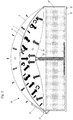
- a membrane gas holder dome 10 with reduced heat loss is illustrated, adapted to be installed on a heated digester adapted to produce combustible gas.
- Said digester consists of a tank 12 made of concrete, having circular shape, provided with a base 12' and a lateral wall 12", adapted to contain sludge or slurry L.
- Said membrane gas holder dome 10 essentially comprises:
- Said gas holder dome 10 comprises inflation means for inflating said pressurization chamber C2 by means of an auxiliary gas, preferably air.
- Said inflation means generally comprise a fan or air compressor 15 and pipes 16 connected to said second membrane. Further accessory elements belonging to the known art in the sector are relief and safety valves for the air 17 and for the gas 18.
- Said first membrane 1 and said second membrane 2 are anchored to the top of the lateral wall 12" of the tank 12 of the digester by flanged mechanical anchoring means of known type.
- a column 13 is provided adapted to support a mesh 14, anchored to the edge of said lateral wall 12", adapted to sustain said first membrane 1, preventing it from touching the free surface of the slurry L contained in the tank 12 during the intermediate phases of filling of the storage chamber C1.
- detection means 19 for detecting the volume of the storage chamber C1 are positioned, adapted to allow measurement of the quantity of gas contained in said chamber.
- Said first membrane 1 and said second membrane 2 are made of polyester fibre fabric 20 covered on both sides by a layer 21 of PVC.
- said gas holder dome 10 comprises a layer of composite material with heat insulating function arranged over said first membrane 1, resting on it.
- Said layer of composite material comprises:
- Said layer of composite material is oriented so that said metal foil 6 is facing said first membrane 1.
- said reflective metal foil 6 is extremely thin to guarantee the composite material maximum flexibility, and comprises an upper micro covering 7 and a lower micro covering 8 in polyethylene, in the order of 10-50 micron.
- Said micro coverings are made of transparent polyethylene.
- said layer of heat insulating composite material is made from one single panel 4 resting on said first membrane 1 (stratigraphy detail of Figure 3 ).
- said layer of heat insulating composite material could be made of several panels 4, associated with one another by means of joints or elastic seals or by means of bindings.
- said composite layer with heat insulating function creates a third membrane 3.
- said third membrane 3, impermeable to gases, is impermeably associated with said second membrane 2 and is adapted to delimit, in cooperation with it, said pressurization chamber C2.
- Said third membrane 3 is therefore interposed between said first membrane 1 and said second membrane 2.
- Said third membrane 3 is advantageously produced so as to rest on said first membrane 1 in a gas permeable manner, to allow any gas leaks to flow out between the two membranes 1, 2 towards the edge, and then to the outside, from any point of the storage chamber.
- the membrane made of plastic material 5 spills over from the layers below, to create projecting edges 4', i.e. a sort of selvage.
- the projecting edges 4' of adjacent panels can be sealed to each other in a gas impermeable manner, since the membrane made of plastic material 5 is heat sealable. In this way, it is possible to cover increasingly large areas, until entirely covering said first membrane 1 with a further membrane impermeable to gases.
Landscapes
- Engineering & Computer Science (AREA)
- Physics & Mathematics (AREA)
- Thermal Sciences (AREA)
- Mechanical Engineering (AREA)
- General Engineering & Computer Science (AREA)
- Separation Using Semi-Permeable Membranes (AREA)
- Cookers (AREA)
- Tents Or Canopies (AREA)
Claims (11)
- Eine Membrangasbehälterkuppel (10) mit reduziertem Wärmeverlust, geeignet, um auf einem beheizten Faulbehälter installiert zu werden, der dazu geeignet ist, brennbares Gas zu erzeugen, umfassend:- eine erste gasundurchlässige Membran (1), die geeignet ist, zumindest teilweise eine Speicherkammer (C1) für das brennbare Gas zu begrenzen;- eine zweite gasundurchlässige Membran (2), die geeignet ist, zumindest teilweise eine Druckkammer (C2) zu begrenzen, die der besagten Speicherkammer (C1) überlagert ist;- Aufblasmittel (15, 16, 17, 18) der besagten Druckkammer (C2) mit Hilfe eines Hilfsgases, vorzugsweise Luft;- eine Schicht aus Verbundmaterial mit wärmeisolierender Funktion, die zwischen der besagten ersten Membran (1) und der besagten zweiten Membran (2) angeordnet ist,wobei die besagte Schicht aus Verbundmaterial Folgendes umfasst:- eine Membran, gefertigt aus Kunststoffmaterial (5), die heißsiegelfähig und gasundurchlässig ist;- eine reflektierende Metallfolie (6);dadurch gekennzeichnet, dass die besagte Schicht aus Verbundmaterial über der besagten ersten Membran (1) angeordnet ist, auf ihr aufliegend, und so ausgerichtet ist, dass die besagte Metallfolie (6) der besagten ersten Membran (1) zugewandt ist.
- Eine Gasbehälterkuppel (10) gemäß Anspruch 1, dadurch gekennzeichnet, dass die besagte Membran aus Kunststoffmaterial (5) eine Platte aus Polyethylen umfasst.
- Eine Gasbehälterkuppel (10) gemäß Anspruch 1, dadurch gekennzeichnet, dass die besagte reflektierende Metallfolie (6) aus Aluminium hergestellt ist.
- Eine Gasbehälterkuppel (10) gemäß Anspruch 1, dadurch gekennzeichnet, dass die besagte reflektierende Metallfolie (6) eine obere Mikroabdeckung (7) und eine untere Mikroabdeckung (8) aus Polyethylen umfasst.
- Eine Gasbehälterkuppel (10) gemäß Anspruch 4, dadurch gekennzeichnet, dass die besagte untere Mikroabdeckung (8) transparent ist.
- Eine Gasbehälterkuppel (10) gemäß Anspruch 1, dadurch gekennzeichnet, dass die besagte Schicht aus Verbundmaterial eine Blasenpolyethylenplatte (9) umfasst, die zwischen der besagten Membran aus Kunststoffmaterial (5) und der besagten reflektierenden Metallfolie (6) eingefügt ist, dazu geeignet, einen Luftspalt (11) zwischen den besagten Schichten zu erzeugen.
- Eine Gasbehälterkuppel (10) gemäß Anspruch 1, dadurch gekennzeichnet, dass sie eine oder mehrere Platten (4) umfasst, die zumindest teilweise aus dem besagten Verbundmaterial hergestellt sind und über der besagten ersten Membran (1) angeordnet sind und mit dieser in Kontakt stehen.
- Eine Gasbehälterkuppel (10) gemäß Anspruch 7, dadurch gekennzeichnet, dass in der besagten Metallfolie (6) Lücken vorgesehen sind.
- Eine Gasbehälterkuppel (10) gemäß Anspruch 7, dadurch gekennzeichnet, dass die besagten Platten (4) mittels elastischer Verbindungen oder mittels Bindungen miteinander verbunden sind.
- Eine Gasbehälterkuppel (10) gemäß Anspruch 1, dadurch gekennzeichnet, dass sie eine dritte gasundurchlässige Membran (3) umfasst, gefertigt aus dem besagten Verbundmaterial mit wärmeisolierender Funktion und mit der besagten zweiten Membran (2) undurchlässig verbunden ist und dazu geeignet ist, in Zusammenarbeit mit dieser die besagte Druckkammer (C2) zu begrenzen.
- Eine Gasbehälterkuppel (10) gemäß den Ansprüchen 7 und 10, dadurch gekennzeichnet, dass die besagten Platten (4) vorspringende Ränder (4') umfassen, die mit der besagten Membran aus Kunststoffmaterial (5) hergestellt sind, und durch Heißsiegeln der besagten vorspringenden Ränder (4') gasundurchlässig miteinander verbunden werden können, so dass die besagte dritte Membran (3) gebildet wird.
Priority Applications (1)
| Application Number | Priority Date | Filing Date | Title |
|---|---|---|---|
| PL17182451T PL3276245T3 (pl) | 2016-07-28 | 2017-07-20 | Membranowa kopuła zbiornika gazu o zmniejszonych stratach ciepła |
Applications Claiming Priority (1)
| Application Number | Priority Date | Filing Date | Title |
|---|---|---|---|
| IT102016000079376A IT201600079376A1 (it) | 2016-07-28 | 2016-07-28 | Copertura gasometrica a membrane a ridotta dispersione di calore |
Publications (2)
| Publication Number | Publication Date |
|---|---|
| EP3276245A1 EP3276245A1 (de) | 2018-01-31 |
| EP3276245B1 true EP3276245B1 (de) | 2021-03-31 |
Family
ID=57610206
Family Applications (1)
| Application Number | Title | Priority Date | Filing Date |
|---|---|---|---|
| EP17182451.9A Active EP3276245B1 (de) | 2016-07-28 | 2017-07-20 | Eine membrangasbehälterkuppel mit reduziertem wärmeverlust |
Country Status (3)
| Country | Link |
|---|---|
| EP (1) | EP3276245B1 (de) |
| IT (1) | IT201600079376A1 (de) |
| PL (1) | PL3276245T3 (de) |
Families Citing this family (2)
| Publication number | Priority date | Publication date | Assignee | Title |
|---|---|---|---|---|
| IT202100006764A1 (it) * | 2021-03-22 | 2022-09-22 | Ecomembrane Srl | Gasometro pneumatico a membrane per lo stoccaggio di idrogeno gassoso a bassa pressione |
| CN113280252B (zh) * | 2021-05-11 | 2022-07-19 | 百穰新能源科技(深圳)有限公司 | 储气库、储能装置、储气库的控制方法与安装方法 |
Family Cites Families (5)
| Publication number | Priority date | Publication date | Assignee | Title |
|---|---|---|---|---|
| DE4120986A1 (de) * | 1991-06-25 | 1993-01-28 | Herrmannsdorfer Entwicklungsge | Abdeckung von oben offenen behaeltern, insbesondere fuer behaelter wie z. b. guellegruben fuer die biogas-erzeugung |
| DE19611475A1 (de) * | 1996-03-22 | 1997-09-25 | Wimmer Ulrich Dipl Ing Fh | Folienelemente |
| ITCR20020001A1 (it) * | 2002-02-21 | 2003-08-21 | Ecomembrane Srl | Accumulatore di gas a membrana |
| DE102005048403A1 (de) * | 2005-10-10 | 2007-04-12 | Verena Herzog-Loibl | Pneumatisch stabilisierte Hülle für ein Gebäude |
| GB2487564B (en) * | 2011-01-27 | 2014-06-04 | Base Structures Ltd | Gas accumulator |
-
2016
- 2016-07-28 IT IT102016000079376A patent/IT201600079376A1/it unknown
-
2017
- 2017-07-20 PL PL17182451T patent/PL3276245T3/pl unknown
- 2017-07-20 EP EP17182451.9A patent/EP3276245B1/de active Active
Non-Patent Citations (1)
| Title |
|---|
| None * |
Also Published As
| Publication number | Publication date |
|---|---|
| PL3276245T3 (pl) | 2021-10-18 |
| IT201600079376A1 (it) | 2018-01-28 |
| EP3276245A1 (de) | 2018-01-31 |
Similar Documents
| Publication | Publication Date | Title |
|---|---|---|
| US3047184A (en) | Storage tank | |
| US5741702A (en) | System for processing gases containing carbon dioxide | |
| US20130029410A1 (en) | Digester tank for a biogas plant | |
| EP3276245A1 (de) | Eine membrangasbehälterkuppel mit reduzierten wärmeverlust | |
| CN102348925B (zh) | 一种液化天然气罐的次级膜封闭区 | |
| CN204548988U (zh) | 一种拼接圆形筒体 | |
| US6360545B1 (en) | Containment enclosure | |
| DK0750569T3 (da) | Beholder til farmaceutiske stoffer | |
| KR20120031312A (ko) | 보강된 주름형 박막을 구비하는 탱크 | |
| US4871081A (en) | Dual wall vessel for primary and secondary liquid containment | |
| NO115290B (de) | ||
| RU2755830C2 (ru) | Герметизированный и теплоизолированный резервуар | |
| KR101477839B1 (ko) | 국제해사기구 규정 Type A방식 독립형 LNG운반선의 화물창 | |
| KR102782852B1 (ko) | 혐기성 이중발효조의 바이오가스 포집시스템 | |
| CN205984290U (zh) | 池式结构反应堆 | |
| US12352736B2 (en) | Pneumatic membrane gasometer for the storage of hydrogen gas at low pressure | |
| KR101291126B1 (ko) | 액화천연가스 저장탱크의 펌프타워 단열구조 | |
| CN205066207U (zh) | 一种太阳能储热水箱 | |
| US10683162B2 (en) | Digester cover left-in-place ballast ring | |
| NO146057B (no) | Analogifremgangsmaate ved fremstilling av terapeutisk aktive aminoalkoholderivater | |
| NO328612B1 (no) | Anordning ved vaeskelas for en gjaeringsbeholder for biologisk materiale | |
| AU2012200754B2 (en) | Vessel with a reinforced corrugated membrane | |
| CN107258652A (zh) | 一种工业化软体养殖池 | |
| FI106873B (fi) | Menetelmä uuttolaitteiston tiivistämiseksi | |
| KR20100027430A (ko) | 태양광을 이용할 수 있는 밀폐구조물의 제조 방법 |
Legal Events
| Date | Code | Title | Description |
|---|---|---|---|
| PUAI | Public reference made under article 153(3) epc to a published international application that has entered the european phase |
Free format text: ORIGINAL CODE: 0009012 |
|
| STAA | Information on the status of an ep patent application or granted ep patent |
Free format text: STATUS: THE APPLICATION HAS BEEN PUBLISHED |
|
| AK | Designated contracting states |
Kind code of ref document: A1 Designated state(s): AL AT BE BG CH CY CZ DE DK EE ES FI FR GB GR HR HU IE IS IT LI LT LU LV MC MK MT NL NO PL PT RO RS SE SI SK SM TR |
|
| AX | Request for extension of the european patent |
Extension state: BA ME |
|
| STAA | Information on the status of an ep patent application or granted ep patent |
Free format text: STATUS: REQUEST FOR EXAMINATION WAS MADE |
|
| 17P | Request for examination filed |
Effective date: 20180725 |
|
| RBV | Designated contracting states (corrected) |
Designated state(s): AL AT BE BG CH CY CZ DE DK EE ES FI FR GB GR HR HU IE IS IT LI LT LU LV MC MK MT NL NO PL PT RO RS SE SI SK SM TR |
|
| GRAP | Despatch of communication of intention to grant a patent |
Free format text: ORIGINAL CODE: EPIDOSNIGR1 |
|
| STAA | Information on the status of an ep patent application or granted ep patent |
Free format text: STATUS: GRANT OF PATENT IS INTENDED |
|
| RIC1 | Information provided on ipc code assigned before grant |
Ipc: F17C 3/02 20060101AFI20201013BHEP |
|
| INTG | Intention to grant announced |
Effective date: 20201112 |
|
| GRAS | Grant fee paid |
Free format text: ORIGINAL CODE: EPIDOSNIGR3 |
|
| GRAA | (expected) grant |
Free format text: ORIGINAL CODE: 0009210 |
|
| STAA | Information on the status of an ep patent application or granted ep patent |
Free format text: STATUS: THE PATENT HAS BEEN GRANTED |
|
| AK | Designated contracting states |
Kind code of ref document: B1 Designated state(s): AL AT BE BG CH CY CZ DE DK EE ES FI FR GB GR HR HU IE IS IT LI LT LU LV MC MK MT NL NO PL PT RO RS SE SI SK SM TR |
|
| REG | Reference to a national code |
Ref country code: GB Ref legal event code: FG4D Ref country code: CH Ref legal event code: EP |
|
| REG | Reference to a national code |
Ref country code: AT Ref legal event code: REF Ref document number: 1377313 Country of ref document: AT Kind code of ref document: T Effective date: 20210415 |
|
| REG | Reference to a national code |
Ref country code: DE Ref legal event code: R096 Ref document number: 602017035558 Country of ref document: DE |
|
| REG | Reference to a national code |
Ref country code: IE Ref legal event code: FG4D |
|
| REG | Reference to a national code |
Ref country code: NL Ref legal event code: FP |
|
| REG | Reference to a national code |
Ref country code: LT Ref legal event code: MG9D |
|
| PG25 | Lapsed in a contracting state [announced via postgrant information from national office to epo] |
Ref country code: BG Free format text: LAPSE BECAUSE OF FAILURE TO SUBMIT A TRANSLATION OF THE DESCRIPTION OR TO PAY THE FEE WITHIN THE PRESCRIBED TIME-LIMIT Effective date: 20210630 Ref country code: NO Free format text: LAPSE BECAUSE OF FAILURE TO SUBMIT A TRANSLATION OF THE DESCRIPTION OR TO PAY THE FEE WITHIN THE PRESCRIBED TIME-LIMIT Effective date: 20210630 Ref country code: FI Free format text: LAPSE BECAUSE OF FAILURE TO SUBMIT A TRANSLATION OF THE DESCRIPTION OR TO PAY THE FEE WITHIN THE PRESCRIBED TIME-LIMIT Effective date: 20210331 Ref country code: HR Free format text: LAPSE BECAUSE OF FAILURE TO SUBMIT A TRANSLATION OF THE DESCRIPTION OR TO PAY THE FEE WITHIN THE PRESCRIBED TIME-LIMIT Effective date: 20210331 |
|
| PG25 | Lapsed in a contracting state [announced via postgrant information from national office to epo] |
Ref country code: SE Free format text: LAPSE BECAUSE OF FAILURE TO SUBMIT A TRANSLATION OF THE DESCRIPTION OR TO PAY THE FEE WITHIN THE PRESCRIBED TIME-LIMIT Effective date: 20210331 Ref country code: RS Free format text: LAPSE BECAUSE OF FAILURE TO SUBMIT A TRANSLATION OF THE DESCRIPTION OR TO PAY THE FEE WITHIN THE PRESCRIBED TIME-LIMIT Effective date: 20210331 Ref country code: LV Free format text: LAPSE BECAUSE OF FAILURE TO SUBMIT A TRANSLATION OF THE DESCRIPTION OR TO PAY THE FEE WITHIN THE PRESCRIBED TIME-LIMIT Effective date: 20210331 |
|
| REG | Reference to a national code |
Ref country code: AT Ref legal event code: MK05 Ref document number: 1377313 Country of ref document: AT Kind code of ref document: T Effective date: 20210331 |
|
| PG25 | Lapsed in a contracting state [announced via postgrant information from national office to epo] |
Ref country code: LT Free format text: LAPSE BECAUSE OF FAILURE TO SUBMIT A TRANSLATION OF THE DESCRIPTION OR TO PAY THE FEE WITHIN THE PRESCRIBED TIME-LIMIT Effective date: 20210331 Ref country code: EE Free format text: LAPSE BECAUSE OF FAILURE TO SUBMIT A TRANSLATION OF THE DESCRIPTION OR TO PAY THE FEE WITHIN THE PRESCRIBED TIME-LIMIT Effective date: 20210331 Ref country code: CZ Free format text: LAPSE BECAUSE OF FAILURE TO SUBMIT A TRANSLATION OF THE DESCRIPTION OR TO PAY THE FEE WITHIN THE PRESCRIBED TIME-LIMIT Effective date: 20210331 Ref country code: AT Free format text: LAPSE BECAUSE OF FAILURE TO SUBMIT A TRANSLATION OF THE DESCRIPTION OR TO PAY THE FEE WITHIN THE PRESCRIBED TIME-LIMIT Effective date: 20210331 Ref country code: SM Free format text: LAPSE BECAUSE OF FAILURE TO SUBMIT A TRANSLATION OF THE DESCRIPTION OR TO PAY THE FEE WITHIN THE PRESCRIBED TIME-LIMIT Effective date: 20210331 |
|
| PG25 | Lapsed in a contracting state [announced via postgrant information from national office to epo] |
Ref country code: SK Free format text: LAPSE BECAUSE OF FAILURE TO SUBMIT A TRANSLATION OF THE DESCRIPTION OR TO PAY THE FEE WITHIN THE PRESCRIBED TIME-LIMIT Effective date: 20210331 Ref country code: RO Free format text: LAPSE BECAUSE OF FAILURE TO SUBMIT A TRANSLATION OF THE DESCRIPTION OR TO PAY THE FEE WITHIN THE PRESCRIBED TIME-LIMIT Effective date: 20210331 Ref country code: PT Free format text: LAPSE BECAUSE OF FAILURE TO SUBMIT A TRANSLATION OF THE DESCRIPTION OR TO PAY THE FEE WITHIN THE PRESCRIBED TIME-LIMIT Effective date: 20210802 Ref country code: IS Free format text: LAPSE BECAUSE OF FAILURE TO SUBMIT A TRANSLATION OF THE DESCRIPTION OR TO PAY THE FEE WITHIN THE PRESCRIBED TIME-LIMIT Effective date: 20210731 |
|
| REG | Reference to a national code |
Ref country code: DE Ref legal event code: R097 Ref document number: 602017035558 Country of ref document: DE |
|
| PG25 | Lapsed in a contracting state [announced via postgrant information from national office to epo] |
Ref country code: ES Free format text: LAPSE BECAUSE OF FAILURE TO SUBMIT A TRANSLATION OF THE DESCRIPTION OR TO PAY THE FEE WITHIN THE PRESCRIBED TIME-LIMIT Effective date: 20210331 Ref country code: AL Free format text: LAPSE BECAUSE OF FAILURE TO SUBMIT A TRANSLATION OF THE DESCRIPTION OR TO PAY THE FEE WITHIN THE PRESCRIBED TIME-LIMIT Effective date: 20210331 Ref country code: DK Free format text: LAPSE BECAUSE OF FAILURE TO SUBMIT A TRANSLATION OF THE DESCRIPTION OR TO PAY THE FEE WITHIN THE PRESCRIBED TIME-LIMIT Effective date: 20210331 |
|
| PLBE | No opposition filed within time limit |
Free format text: ORIGINAL CODE: 0009261 |
|
| STAA | Information on the status of an ep patent application or granted ep patent |
Free format text: STATUS: NO OPPOSITION FILED WITHIN TIME LIMIT |
|
| 26N | No opposition filed |
Effective date: 20220104 |
|
| GBPC | Gb: european patent ceased through non-payment of renewal fee |
Effective date: 20210720 |
|
| PG25 | Lapsed in a contracting state [announced via postgrant information from national office to epo] |
Ref country code: MC Free format text: LAPSE BECAUSE OF FAILURE TO SUBMIT A TRANSLATION OF THE DESCRIPTION OR TO PAY THE FEE WITHIN THE PRESCRIBED TIME-LIMIT Effective date: 20210331 |
|
| REG | Reference to a national code |
Ref country code: BE Ref legal event code: MM Effective date: 20210731 |
|
| PG25 | Lapsed in a contracting state [announced via postgrant information from national office to epo] |
Ref country code: GB Free format text: LAPSE BECAUSE OF NON-PAYMENT OF DUE FEES Effective date: 20210720 |
|
| PG25 | Lapsed in a contracting state [announced via postgrant information from national office to epo] |
Ref country code: IS Free format text: LAPSE BECAUSE OF FAILURE TO SUBMIT A TRANSLATION OF THE DESCRIPTION OR TO PAY THE FEE WITHIN THE PRESCRIBED TIME-LIMIT Effective date: 20210731 Ref country code: LU Free format text: LAPSE BECAUSE OF NON-PAYMENT OF DUE FEES Effective date: 20210720 |
|
| PG25 | Lapsed in a contracting state [announced via postgrant information from national office to epo] |
Ref country code: IE Free format text: LAPSE BECAUSE OF NON-PAYMENT OF DUE FEES Effective date: 20210720 Ref country code: BE Free format text: LAPSE BECAUSE OF NON-PAYMENT OF DUE FEES Effective date: 20210731 |
|
| PG25 | Lapsed in a contracting state [announced via postgrant information from national office to epo] |
Ref country code: HU Free format text: LAPSE BECAUSE OF FAILURE TO SUBMIT A TRANSLATION OF THE DESCRIPTION OR TO PAY THE FEE WITHIN THE PRESCRIBED TIME-LIMIT; INVALID AB INITIO Effective date: 20170720 |
|
| PG25 | Lapsed in a contracting state [announced via postgrant information from national office to epo] |
Ref country code: CY Free format text: LAPSE BECAUSE OF FAILURE TO SUBMIT A TRANSLATION OF THE DESCRIPTION OR TO PAY THE FEE WITHIN THE PRESCRIBED TIME-LIMIT Effective date: 20210331 |
|
| PG25 | Lapsed in a contracting state [announced via postgrant information from national office to epo] |
Ref country code: GR Free format text: LAPSE BECAUSE OF FAILURE TO SUBMIT A TRANSLATION OF THE DESCRIPTION OR TO PAY THE FEE WITHIN THE PRESCRIBED TIME-LIMIT Effective date: 20210331 |
|
| P01 | Opt-out of the competence of the unified patent court (upc) registered |
Effective date: 20230801 |
|
| PGFP | Annual fee paid to national office [announced via postgrant information from national office to epo] |
Ref country code: CH Payment date: 20230802 Year of fee payment: 7 |
|
| PG25 | Lapsed in a contracting state [announced via postgrant information from national office to epo] |
Ref country code: MK Free format text: LAPSE BECAUSE OF FAILURE TO SUBMIT A TRANSLATION OF THE DESCRIPTION OR TO PAY THE FEE WITHIN THE PRESCRIBED TIME-LIMIT Effective date: 20210331 |
|
| PG25 | Lapsed in a contracting state [announced via postgrant information from national office to epo] |
Ref country code: MT Free format text: LAPSE BECAUSE OF FAILURE TO SUBMIT A TRANSLATION OF THE DESCRIPTION OR TO PAY THE FEE WITHIN THE PRESCRIBED TIME-LIMIT Effective date: 20210331 |
|
| REG | Reference to a national code |
Ref country code: CH Ref legal event code: PL |
|
| PG25 | Lapsed in a contracting state [announced via postgrant information from national office to epo] |
Ref country code: CH Free format text: LAPSE BECAUSE OF NON-PAYMENT OF DUE FEES Effective date: 20240731 |
|
| PGFP | Annual fee paid to national office [announced via postgrant information from national office to epo] |
Ref country code: NL Payment date: 20250726 Year of fee payment: 9 |
|
| PGFP | Annual fee paid to national office [announced via postgrant information from national office to epo] |
Ref country code: DE Payment date: 20250729 Year of fee payment: 9 |
|
| PGFP | Annual fee paid to national office [announced via postgrant information from national office to epo] |
Ref country code: PL Payment date: 20250702 Year of fee payment: 9 Ref country code: IT Payment date: 20250612 Year of fee payment: 9 |
|
| PGFP | Annual fee paid to national office [announced via postgrant information from national office to epo] |
Ref country code: FR Payment date: 20250725 Year of fee payment: 9 |
|
| PG25 | Lapsed in a contracting state [announced via postgrant information from national office to epo] |
Ref country code: TR Free format text: LAPSE BECAUSE OF FAILURE TO SUBMIT A TRANSLATION OF THE DESCRIPTION OR TO PAY THE FEE WITHIN THE PRESCRIBED TIME-LIMIT Effective date: 20210331 |