EP3276198A1 - Boot attachment method and constant velocity universal joint - Google Patents
Boot attachment method and constant velocity universal joint Download PDFInfo
- Publication number
- EP3276198A1 EP3276198A1 EP16768323.4A EP16768323A EP3276198A1 EP 3276198 A1 EP3276198 A1 EP 3276198A1 EP 16768323 A EP16768323 A EP 16768323A EP 3276198 A1 EP3276198 A1 EP 3276198A1
- Authority
- EP
- European Patent Office
- Prior art keywords
- boot
- frequency induction
- induction heating
- end portion
- mounting
- Prior art date
- Legal status (The legal status is an assumption and is not a legal conclusion. Google has not performed a legal analysis and makes no representation as to the accuracy of the status listed.)
- Granted
Links
- 238000000034 method Methods 0.000 title claims abstract description 69
- 238000010438 heat treatment Methods 0.000 claims abstract description 254
- 230000006698 induction Effects 0.000 claims abstract description 245
- 230000013011 mating Effects 0.000 claims abstract description 125
- 239000002184 metal Substances 0.000 claims abstract description 26
- 229910052751 metal Inorganic materials 0.000 claims abstract description 26
- 239000011810 insulating material Substances 0.000 claims description 40
- 239000000463 material Substances 0.000 claims description 40
- 229920000728 polyester Polymers 0.000 claims description 13
- 229920001971 elastomer Polymers 0.000 claims description 12
- 239000000806 elastomer Substances 0.000 claims description 11
- 229920001169 thermoplastic Polymers 0.000 claims description 11
- 239000004416 thermosoftening plastic Substances 0.000 claims description 11
- 229910010272 inorganic material Inorganic materials 0.000 claims description 8
- 230000005540 biological transmission Effects 0.000 claims description 6
- 230000002093 peripheral effect Effects 0.000 claims description 6
- 150000002484 inorganic compounds Chemical class 0.000 claims description 4
- 230000009471 action Effects 0.000 abstract description 11
- 238000005304 joining Methods 0.000 description 47
- 230000000694 effects Effects 0.000 description 16
- 230000005674 electromagnetic induction Effects 0.000 description 16
- 229920005989 resin Polymers 0.000 description 12
- 239000011347 resin Substances 0.000 description 12
- 239000000853 adhesive Substances 0.000 description 8
- 230000001070 adhesive effect Effects 0.000 description 8
- 238000011156 evaluation Methods 0.000 description 8
- 239000004519 grease Substances 0.000 description 8
- 230000033001 locomotion Effects 0.000 description 8
- 238000000354 decomposition reaction Methods 0.000 description 7
- 230000009467 reduction Effects 0.000 description 7
- 239000007787 solid Substances 0.000 description 7
- 239000000919 ceramic Substances 0.000 description 6
- 239000012811 non-conductive material Substances 0.000 description 6
- 238000012546 transfer Methods 0.000 description 5
- RYGMFSIKBFXOCR-UHFFFAOYSA-N Copper Chemical compound [Cu] RYGMFSIKBFXOCR-UHFFFAOYSA-N 0.000 description 4
- 239000002826 coolant Substances 0.000 description 4
- 229910052802 copper Inorganic materials 0.000 description 4
- 239000010949 copper Substances 0.000 description 4
- 239000000428 dust Substances 0.000 description 4
- 239000011491 glass wool Substances 0.000 description 4
- 239000011147 inorganic material Substances 0.000 description 4
- 230000008569 process Effects 0.000 description 4
- 238000007789 sealing Methods 0.000 description 4
- 238000011144 upstream manufacturing Methods 0.000 description 4
- 238000001816 cooling Methods 0.000 description 3
- 239000011295 pitch Substances 0.000 description 3
- 238000012360 testing method Methods 0.000 description 3
- XLYOFNOQVPJJNP-UHFFFAOYSA-N water Substances O XLYOFNOQVPJJNP-UHFFFAOYSA-N 0.000 description 3
- 240000006829 Ficus sundaica Species 0.000 description 2
- 238000005452 bending Methods 0.000 description 2
- 230000015572 biosynthetic process Effects 0.000 description 2
- 230000015556 catabolic process Effects 0.000 description 2
- 239000004568 cement Substances 0.000 description 2
- 238000006731 degradation reaction Methods 0.000 description 2
- 230000005489 elastic deformation Effects 0.000 description 2
- 239000000835 fiber Substances 0.000 description 2
- 230000004048 modification Effects 0.000 description 2
- 238000012986 modification Methods 0.000 description 2
- 229920002379 silicone rubber Polymers 0.000 description 2
- 239000004945 silicone rubber Substances 0.000 description 2
- 229920002725 thermoplastic elastomer Polymers 0.000 description 2
- YCKRFDGAMUMZLT-UHFFFAOYSA-N Fluorine atom Chemical compound [F] YCKRFDGAMUMZLT-UHFFFAOYSA-N 0.000 description 1
- 239000004793 Polystyrene Substances 0.000 description 1
- BZHJMEDXRYGGRV-UHFFFAOYSA-N Vinyl chloride Chemical compound ClC=C BZHJMEDXRYGGRV-UHFFFAOYSA-N 0.000 description 1
- 238000009825 accumulation Methods 0.000 description 1
- 210000000078 claw Anatomy 0.000 description 1
- 238000003776 cleavage reaction Methods 0.000 description 1
- 230000008602 contraction Effects 0.000 description 1
- 229910052731 fluorine Inorganic materials 0.000 description 1
- 239000011737 fluorine Substances 0.000 description 1
- 239000006260 foam Substances 0.000 description 1
- 238000005242 forging Methods 0.000 description 1
- 238000004519 manufacturing process Methods 0.000 description 1
- 230000007246 mechanism Effects 0.000 description 1
- 239000007769 metal material Substances 0.000 description 1
- 230000010355 oscillation Effects 0.000 description 1
- 230000010399 physical interaction Effects 0.000 description 1
- 229920002647 polyamide Polymers 0.000 description 1
- 229920000098 polyolefin Polymers 0.000 description 1
- 229920001296 polysiloxane Polymers 0.000 description 1
- 229920002223 polystyrene Polymers 0.000 description 1
- 229920002635 polyurethane Polymers 0.000 description 1
- 239000004814 polyurethane Substances 0.000 description 1
- 238000012545 processing Methods 0.000 description 1
- 238000005096 rolling process Methods 0.000 description 1
- 230000007017 scission Effects 0.000 description 1
- 229920006346 thermoplastic polyester elastomer Polymers 0.000 description 1
- 230000003313 weakening effect Effects 0.000 description 1
Images











Classifications
-
- F—MECHANICAL ENGINEERING; LIGHTING; HEATING; WEAPONS; BLASTING
- F16—ENGINEERING ELEMENTS AND UNITS; GENERAL MEASURES FOR PRODUCING AND MAINTAINING EFFECTIVE FUNCTIONING OF MACHINES OR INSTALLATIONS; THERMAL INSULATION IN GENERAL
- F16D—COUPLINGS FOR TRANSMITTING ROTATION; CLUTCHES; BRAKES
- F16D3/00—Yielding couplings, i.e. with means permitting movement between the connected parts during the drive
- F16D3/84—Shrouds, e.g. casings, covers; Sealing means specially adapted therefor
- F16D3/843—Shrouds, e.g. casings, covers; Sealing means specially adapted therefor enclosed covers
- F16D3/845—Shrouds, e.g. casings, covers; Sealing means specially adapted therefor enclosed covers allowing relative movement of joint parts due to the flexing of the cover
-
- B—PERFORMING OPERATIONS; TRANSPORTING
- B29—WORKING OF PLASTICS; WORKING OF SUBSTANCES IN A PLASTIC STATE IN GENERAL
- B29C—SHAPING OR JOINING OF PLASTICS; SHAPING OF MATERIAL IN A PLASTIC STATE, NOT OTHERWISE PROVIDED FOR; AFTER-TREATMENT OF THE SHAPED PRODUCTS, e.g. REPAIRING
- B29C65/00—Joining or sealing of preformed parts, e.g. welding of plastics materials; Apparatus therefor
- B29C65/02—Joining or sealing of preformed parts, e.g. welding of plastics materials; Apparatus therefor by heating, with or without pressure
- B29C65/18—Joining or sealing of preformed parts, e.g. welding of plastics materials; Apparatus therefor by heating, with or without pressure using heated tools
- B29C65/24—Joining or sealing of preformed parts, e.g. welding of plastics materials; Apparatus therefor by heating, with or without pressure using heated tools characterised by the means for heating the tool
- B29C65/30—Electrical means
- B29C65/32—Induction
-
- B—PERFORMING OPERATIONS; TRANSPORTING
- B29—WORKING OF PLASTICS; WORKING OF SUBSTANCES IN A PLASTIC STATE IN GENERAL
- B29C—SHAPING OR JOINING OF PLASTICS; SHAPING OF MATERIAL IN A PLASTIC STATE, NOT OTHERWISE PROVIDED FOR; AFTER-TREATMENT OF THE SHAPED PRODUCTS, e.g. REPAIRING
- B29C66/00—General aspects of processes or apparatus for joining preformed parts
- B29C66/70—General aspects of processes or apparatus for joining preformed parts characterised by the composition, physical properties or the structure of the material of the parts to be joined; Joining with non-plastics material
- B29C66/74—Joining plastics material to non-plastics material
- B29C66/742—Joining plastics material to non-plastics material to metals or their alloys
-
- F—MECHANICAL ENGINEERING; LIGHTING; HEATING; WEAPONS; BLASTING
- F16—ENGINEERING ELEMENTS AND UNITS; GENERAL MEASURES FOR PRODUCING AND MAINTAINING EFFECTIVE FUNCTIONING OF MACHINES OR INSTALLATIONS; THERMAL INSULATION IN GENERAL
- F16D—COUPLINGS FOR TRANSMITTING ROTATION; CLUTCHES; BRAKES
- F16D3/00—Yielding couplings, i.e. with means permitting movement between the connected parts during the drive
- F16D3/84—Shrouds, e.g. casings, covers; Sealing means specially adapted therefor
-
- F—MECHANICAL ENGINEERING; LIGHTING; HEATING; WEAPONS; BLASTING
- F16—ENGINEERING ELEMENTS AND UNITS; GENERAL MEASURES FOR PRODUCING AND MAINTAINING EFFECTIVE FUNCTIONING OF MACHINES OR INSTALLATIONS; THERMAL INSULATION IN GENERAL
- F16J—PISTONS; CYLINDERS; SEALINGS
- F16J15/00—Sealings
- F16J15/50—Sealings between relatively-movable members, by means of a sealing without relatively-moving surfaces, e.g. fluid-tight sealings for transmitting motion through a wall
- F16J15/52—Sealings between relatively-movable members, by means of a sealing without relatively-moving surfaces, e.g. fluid-tight sealings for transmitting motion through a wall by means of sealing bellows or diaphragms
-
- F—MECHANICAL ENGINEERING; LIGHTING; HEATING; WEAPONS; BLASTING
- F16—ENGINEERING ELEMENTS AND UNITS; GENERAL MEASURES FOR PRODUCING AND MAINTAINING EFFECTIVE FUNCTIONING OF MACHINES OR INSTALLATIONS; THERMAL INSULATION IN GENERAL
- F16J—PISTONS; CYLINDERS; SEALINGS
- F16J3/00—Diaphragms; Bellows; Bellows pistons
- F16J3/04—Bellows
-
- F—MECHANICAL ENGINEERING; LIGHTING; HEATING; WEAPONS; BLASTING
- F16—ENGINEERING ELEMENTS AND UNITS; GENERAL MEASURES FOR PRODUCING AND MAINTAINING EFFECTIVE FUNCTIONING OF MACHINES OR INSTALLATIONS; THERMAL INSULATION IN GENERAL
- F16J—PISTONS; CYLINDERS; SEALINGS
- F16J3/00—Diaphragms; Bellows; Bellows pistons
- F16J3/04—Bellows
- F16J3/041—Non-metallic bellows
- F16J3/042—Fastening details
-
- B—PERFORMING OPERATIONS; TRANSPORTING
- B29—WORKING OF PLASTICS; WORKING OF SUBSTANCES IN A PLASTIC STATE IN GENERAL
- B29K—INDEXING SCHEME ASSOCIATED WITH SUBCLASSES B29B, B29C OR B29D, RELATING TO MOULDING MATERIALS OR TO MATERIALS FOR MOULDS, REINFORCEMENTS, FILLERS OR PREFORMED PARTS, e.g. INSERTS
- B29K2667/00—Use of polyesters or derivatives thereof for preformed parts, e.g. for inserts
-
- F—MECHANICAL ENGINEERING; LIGHTING; HEATING; WEAPONS; BLASTING
- F16—ENGINEERING ELEMENTS AND UNITS; GENERAL MEASURES FOR PRODUCING AND MAINTAINING EFFECTIVE FUNCTIONING OF MACHINES OR INSTALLATIONS; THERMAL INSULATION IN GENERAL
- F16D—COUPLINGS FOR TRANSMITTING ROTATION; CLUTCHES; BRAKES
- F16D3/00—Yielding couplings, i.e. with means permitting movement between the connected parts during the drive
- F16D3/16—Universal joints in which flexibility is produced by means of pivots or sliding or rolling connecting parts
- F16D3/20—Universal joints in which flexibility is produced by means of pivots or sliding or rolling connecting parts one coupling part entering a sleeve of the other coupling part and connected thereto by sliding or rolling members
- F16D3/22—Universal joints in which flexibility is produced by means of pivots or sliding or rolling connecting parts one coupling part entering a sleeve of the other coupling part and connected thereto by sliding or rolling members the rolling members being balls, rollers, or the like, guided in grooves or sockets in both coupling parts
- F16D3/223—Universal joints in which flexibility is produced by means of pivots or sliding or rolling connecting parts one coupling part entering a sleeve of the other coupling part and connected thereto by sliding or rolling members the rolling members being balls, rollers, or the like, guided in grooves or sockets in both coupling parts the rolling members being guided in grooves in both coupling parts
- F16D2003/22316—Means for fastening or attaching the bellows or gaiters
-
- F—MECHANICAL ENGINEERING; LIGHTING; HEATING; WEAPONS; BLASTING
- F16—ENGINEERING ELEMENTS AND UNITS; GENERAL MEASURES FOR PRODUCING AND MAINTAINING EFFECTIVE FUNCTIONING OF MACHINES OR INSTALLATIONS; THERMAL INSULATION IN GENERAL
- F16D—COUPLINGS FOR TRANSMITTING ROTATION; CLUTCHES; BRAKES
- F16D2250/00—Manufacturing; Assembly
- F16D2250/0084—Assembly or disassembly
Definitions
- the present invention relates to a boot mounting method for a constant velocity universal joint, and to a constant velocity universal joint which is constructed using the boot mounting method.
- a boot (boot for a constant velocity universal joint) is mounted for the purpose of preventing entry of foreign matters such as dust into the joint and preventing leakage of grease sealed in the joint.
- a constant velocity universal joint (fixed type constant velocity universal joint) includes an outer joint member 3, an inner joint member 6, a plurality of balls 7, and a cage 8.
- the outer joint member 3 has a plurality of track grooves 1, which are formed in a radially inner surface 2 and extend in an axial direction.
- the inner joint member 6 has a plurality of track grooves 4, which are formed in a radially outer surface 5 at equal intervals along a circumferential direction and extend in the axial direction.
- the plurality of balls 7 are interposed between the track grooves 1 of the outer joint member 3 and the track grooves 4 of the inner joint member 6 and are configured to transmit torque .
- the cage 8 is interposed between the radially inner surface 2 of the outer joint member 3 and the radially outer surface 5 of the inner joint member 6 and is configured to retain the balls 7.
- a female spline 9 is formed along an inner periphery of an axial center hole of the inner joint member 6, and an end portion male spline 11 of a shaft 10 is fitted into the axial center hole of the inner joint member 6 so that the female spline 9 and the end portion male spline 11 are fitted to each other. Further, the end portion male spline 11 of the shaft 10 has a circumferential groove 12. A stop ring 13 serving as a stopper is mounted to the circumferential groove 12.
- the boot 15 includes a large-diameter mounting portion 15a, a small-diameter mounting portion 15b, and a bellows portion 15c connecting the large-diameter mounting portion 15a and the small-diameter mounting portion 15b to each other.
- the large-diameter mounting portion 15a of the boot 15 is fastened and fixed by a fastening band 16 at an opening end of the outer joint member 3, and the small-diameter mounting portion of the boot 15 is fastened and fixed by a fastening band 17 at a predetermined portion of the shaft 10.
- the lever type boot band includes a band main body and a lever.
- the band main body is formed on a ring portion.
- the lever is provided to a joined portion of the band main body.
- the lever is folded back so that an inner surface of the lever overlaps a radially outer surface of the band main body.
- Patent Literature 2 a fastening band using an engagement claw and an engagement hole. According to the fastening band disclosed in Patent Literature 2, an ear portion protruding radially outward is formed, and the ear portion is compressed to reduce a diameter of a ring portion.
- Patent Literature 3 high-frequency induction
- Patent Literature 4 laser light
- a high-frequency induction heating coil is arranged on an outer peripheral portion of the boot end portion, and a high-frequency current is applied to the high-frequency induction heating coil.
- the receiving surface of the mating member having conductivity is heated by high-frequency waves through the boot end portion, with the result that the boot end portion and the receiving surface of the mating member are joined and integrated to each other by the heat.
- a metal material and a resin material are joined to each other by a physical interaction caused by irradiation of laser light from a resin material surface side.
- the electromagnetic induction heating with high-frequency waves is generally used in, for example, heat treatment for metal.
- This heating method involves self-heating through use of an induced current generated in a heated object. Therefore, only a material having conductivity can be heated, and a non-conductive material is not heated.
- a clearance (gap) needs to be formed between the coil and the heated object. This is because the coil is damaged when the coil that is electrified is brought into contact with the heated object. Further, rapid heating and surface heating can be performed through use of the high-frequency induction, and a heating temperature is changed in accordance with an oscillation frequency, a current, and a distance (gap amount) between the coil and the heated object.
- the high-frequency induction heating coil so as to be coaxial with a shaft or an outer joint member.
- the gap amount between the coil and the shaft or between the coil and the outer joint member is not uniform in any phase in the circumferential direction, surface temperatures in respective phases may vary, with the result that the joining strength may also vary.
- there is difficulty in arranging the coil so as to be coaxial with the shaft or the outer joint member with high accuracy and there is a fear in that a uniform gap amount cannot be set.
- the electromagnetic induction heating often causes the rise in temperature of the coil itself by transferred heat or radiant heat from the heated object. Therefore, when the electromagnetic induction heating is used in heat treatment for metal, the coil is also cooled together with the heated object by a coolant or the like, with the result that accumulation of heat in the coil due to the transferred heat or the radiant heat from the heated object is cancelled.
- the method using the laser light requires a laser irradiation device, and it is necessary to irradiate the laser light to an irradiated portion over an entire periphery in a circumferential direction and over an entire length in an axial direction. Therefore, the device is complicated, with the result that the cost is increased.
- the fixing of the boot requires a joining strength, which can tolerate generation of a rotary force caused by a differential motion in a case of expansion and contraction of the boot or a contact with the bellows, and a function of preventing leakage from the boot. Therefore, consideration is made of the case where the non-adhering portion or the like is formed in the joined portion corresponding to the mating portion of the coil.
- the joining strength can be compensated through increase in a joining area. Meanwhile, with regard to the leakage of grease, the leakage of grease is more liable to occur when there is any phase in which the boot is not joined in the circumferential direction.
- the receiving surface being the radially outer surface of the mating member is a cylindrical surface, and hence the method using the high-frequency induction cannot achieve an effect of causing an adhesive to enter a hole or a cleavage of a material surface and be hardened thereat (anchor effect) . Therefore, there is difficulty in obtaining a large joining strength.
- a first object of the present invention is to provide a boot mounting method which is capable of achieving a uniform adhesive strength (joining strength) in a circumferential direction and obtaining a stable joining strength, and to provide a constant velocity universal joint using the boot mounting method.
- a second object of the present invention is to provide a boot mounting method which prevents loss of sealability even when joining is performed under a state in which employment of a separable coil causes a gap formed between mating surfaces of the separable coil and in which portions corresponding to the joining surfaces are in non-contact state, and to provide a constant velocity universal joint using the boot mounting method.
- a third object of the present invention is to provide a boot mounting method which is capable of achieving a uniform adhesive strength (joining strength) in the circumferential direction to obtain a stable joining strength, achieving longer lifetime of the high-frequency induction heating coil which is to be used, and obtaining a stable output, and to provide a constant velocity universal joint by the boot mounting method.
- a fourth object of the present invention is to provide a boot mounting method which is capable of obtaining a stable and large joining strength, and to provide a constant velocity universal joint by the boot mounting method.
- a boot mounting method for a constant velocity universal joint in which a boot end portion is mounted and fixed to a mating member made of metal, the boot mounting method comprising: fitting the boot end portion over a receiving surface being a radially outer surface of the mating member; fitting a high-frequency induction heating coil having a ring shape over the boot end portion; and heating only a top portion of the receiving surface of the mating member by high-frequency induction through application of a high-frequency current to the high-frequency induction heating coil so that a mounting surface being a radially inner surface of the boot end portion and the receiving surface being the radially outer surface of the mating member are integrally joined to each other.
- the electromagnetic induction causes the mating member made of metal being a conductive member to generate heat through core loss (sum of eddy current loss and hysteresis loss).
- the heat causes a boundary portion of the boot end portion in contact with the mating member to be rapidly heated to a temperature equal to or higher than a decomposition temperature, and then the boundary portion of the boot end portion is decomposed, thereby generating bubbles.
- high-temperature and high-pressure conditions are given to the high-temperature melt in the periphery of the above-mentioned bubbles and to the surface of the mating member.
- the joined portion is obtained between the mounting surface of the boot end portion and the receiving surface of the mating member.
- the boot end portion is mounted and fixed to the mating member made of metal.
- the boot end portion is present (interposed) between the high-frequency induction heating coil and the heated object (mating member) .
- the boot material is resin, which is a non-conductive material. Therefore, even when the high-frequency induction heating coil and the boot end portion are brought into contact with each other, the high-frequency induction heating coil is prevented from being broken. Further, the thickness of the boot end portion is generally constant. Therefore, when the high-frequency induction heating coil is brought into contact with a radially outer portion (non-adhering surface) of the mounting surface of the boot end portion, a gap formed between the mating member being the heated object and the high-frequency induction heating coil can be maintained accurately in the circumferential direction.
- the high-frequency induction heating coil having the ring shape may be fitted over the boot end portion under a state in which a heat-insulating material is interposed between an inner peripheral surface of the high-frequency induction heating coil and the boot end portion.
- a heat-insulating material is interposed as described above, the heat-insulating material and the boot end portion are present (interposed) between the high-frequency induction heating coil and the heated object (mating member), thereby being capable of suppressing transfer of heat to the coil.
- the boot material is resin, which is a non-conductive material. Therefore, even when the high-frequency induction heating coil is brought into contact with the boot end portion through intermediation of the heat-insulating material, the high-frequency induction heating coil is prevented from being broken.
- the thickness of the boot end portion is generally constant. Therefore, when the high-frequency induction heating coil is brought into contact with the radially outer portion (non-adhering surface) of the mounting surface of the boot end port ion, a gap formed between the mating member being the heated object and the high-frequency induction heating coil can be maintained accurately in the circumferential direction.
- heating be performed by high-frequency induction under the state in which the non-mounting surface being the radially outer surface of the boot end portion and the radially inner surface of the heat-insulating material are held in contact with each other and in which the radially outer surface of the heat-insulating material and the radially inner surface of the high-frequency induction heating coil are held in contact with each other.
- a gap between the high-frequency induction heating coil and the mated member can be set uniform over an entire periphery in the circumferential direction.
- the heat-insulating material may be a general heat-insulating material such as ceramics, glass wool, ceramics fiber, cement plate, or silicone rubber. However, it is preferred that the heat-insulating material be made of an inorganic compound (inorganic material) such as ceramics or glass wool having high heat resistance.
- a slit may be formed in the receiving surface being the radially outer surface of the mating member, and after the boot end portion is fitted over the receiving surface of the mating member, the high-frequency induction heating coil having the ring shape may be fitted over the boot end portion.
- the boot material melted by the high-frequency induction enters the slit. That is, the boot material enters a space formed in the receiving surface and is hardened therein, thereby achieving the anchor effect. Further, through formation of the slit in the receiving surface being a cylindrical surface, an edge portion is formed. The proximity effect of the electromagnetic induction causes the edge portion of the slit to be more likely to raise its temperature, and a desired temperature can be obtained over a wide range of the coil contact surface (boot joining surface).
- the slit formed in the receiving surface of the mating member may have a depth set within a range of from 0.1 mm to 1 mm.
- the depth of the slit is more than 1 mm, the slit is excessively deep, with the result that the strength of the mating member (outer joint member or shaft) is degraded.
- the electromagnetic induction is performed at high frequency for a short period of time. Therefore, there is a fear in that heating is less likely to be performed.
- the anchor effect of causing the boot material to enter the space formed in the receiving surface and be hardened therein is less likely to be achieved, and the proximity effect by the electromagnetic induction is less likely to be obtained.
- the high-frequency induction heating coil comprise a dividable ring member comprising two arcuate members combined with each other, and that a contact between the radially inner surface of the high-frequency induction heating coil and the radially outer surface being the non-mounting surface of the boot end portion have an interference. Even a small interference in the boot may stabilize the gap amount of the joined portion in the circumferential direction. Further, when the interference is excessively large, the coil cannot be fully closed, with the result that the function cannot be achieved, that is, the high-frequency induction heating coil cannot be constructed. Therefore, in this case, it is preferred that an interference of from 0.05 mm to 0.3 mm be set.
- each mating surface of the high-frequency induction heating coil has a stepped structure, and the non-joined portion or the portion having a small joining strength has a so-called labyrinth structure.
- the stepped structure may comprise: a protruding portion formed on the mating surface of one of the arcuate members; and a recessed portion, which is formed in the mating surface of another of the arcuate members and receives the protruding portion fitted to the recessed portion.
- a diameter (inner diameter) of the mounting surface of the boot end portion and a diameter (outer diameter) of the receiving surface of the mating member have an interference corresponding to a ratio of from 0.995 to 0.98.
- the diameter ratio between the mounting surface of the boot end portion and the receiving surface of the mating member is less than 0.995 (smaller interference)
- a microscopic contact between the metal and the boot material is poor.
- the interference is larger than 0.98 (larger interference)
- the press-fit resistance of the boot is large, with the result that there is a fear in that assembly is hindered.
- the high-frequency induction heating coil may comprise a non-dividable ring member, and the radially inner surface of the high-frequency induction heating coil and the radially outer surface being the non-mounting surface of the boot end portion each may have a tapered surface reduced in diameter from a boot bellows portion side toward a boot end portion side. With such setting, the side of the high-frequency induction heating coil, which is larger in diameter, can be fitted into the boot end portion from a small-diameter side of the boot end portion.
- the tapered surface may have a taper angle of from 5° to 30°. This is based on the moldability of the boot. When the taper angle is less than 5°, the ease of fitting is degraded. When the taper angle is more than 30°, a gap of the coil with respect to the heated portion significantly differs at an axial end portion. Therefore, there is a fear in that the surface temperature of the mating member may vary.
- the boot material be thermoplastic polyester-based elastomer.
- the thermoplastic polyester-based elastomer is excellent in mechanical strength, moldability, and elasticity, and hence is preferred as a material providing functions such as bending resistance required for the boot.
- a first constant velocity universal joint comprising: an outer joint member; an inner joint member; and a torque transmission member interposed between the outer joint member and the inner joint member, the outer joint member having an opening portion sealed with a boot, the boot comprising: a large-diameter mounting portion mounted to a boot receiving portion formed in a radially outer surface on the opening portion side of the outer joint member; a small-diameter mounting portion mounted to a boot receiving portion of a shaft fitted into the inner joint member; and a bent portion connecting the large-diameter mounting portion and the small-diametermounting portion, the large-diameter mounting portion of the boot being the boot end portion, the boot receiving portion formed in the radially outer surface of the outer joint member on the opening portion side being the receiving surface of the mating member, the large-diameter mounting portion of the boot and the boot receiving portion of the outer joint member being integrally joined to each other through use of the boot mounting method.
- a second constant velocity universal joint comprising: an outer joint member; an inner joint member; and a torque transmission member interposed between the outer joint member and the inner joint member, the outer joint member having the opening portion sealed with a boot, the boot comprising: a large-diameter mounting portion mounted to a boot receiving portion formed in a radially outer surface on an opening portion side of the outer joint member; a small-diameter mounting portion mounted to a boot receiving portion of a shaft fitted into the inner joint member; and a bent portion connecting the large-diameter mounting portion and the small-diameter mounting portion, the small-diameter mounting portion of the boot being the boot end portion, the boot receiving portion of the shaft being the receiving surface of the mating member, the small-diameter mounting portion of the boot and the boot receiving portion of the shaft being integrally joined to each other through use of the boot mounting method.
- a gap formed between the mating member being the heated object and the high-frequency induction heating coil can be maintained accurately in the circumferential direction. Therefore, the adhesive strength (joining strength) in the circumferential direction is uniform, thereby achieving the stable joining strength. Further, relative movement between the mating member and the high-frequency induction heating coil is not required. Therefore, is possible to reduce the size and weight of the high-frequency induction heating device which comprises the high-frequency induction heating coil, thus contributing to reduction in cost.
- the heat-insulating material and the boot end portion are present (interposed) between the high-frequency induction heating coil and the heated object (mating member), thereby being capable of suppressing transfer of heat to the coil. Therefore, there are advantages in that the stable output and joining strength can be obtained even during continuous use and that longer lifetime of the coil can be achieved. Further, adhesion of the boot material and the coil caused by the rise in temperature of the coil can be prevented, thereby being excellent in operability.
- a gap formed between the mating member being the heated object and the high-frequency induction heating coil can be maintained accurately in the circumferential direction. Therefore, the adhesive strength (joining strength) in the circumferential direction is uniform, thereby achieving the stable joining strength. Further, relative movement between the mating member and the high-frequency induction heating coil is not required. Therefore, is possible to reduce the size and weight of the high-frequency induction heating device which comprises the high-frequency induction heating coil, thus contributing to reduction in cost.
- the inorganic material inorganic compound
- excellent heat resistance and durability can be achieved.
- the joining strength between the boot end portion and the mating member is increased by the anchor effect and the proximity effect of the electromagnetic induction. Therefore, the stable joining strength is achieved between the boot end portion and the mating member, thereby being capable of achieving highly accurate sealing performance during rotation under the state in which the constant velocity universal joint takes the operating angle. Further, relative movement between the mating member and the high-frequency induction heating coil is not required. Therefore, is possible to reduce the size and weight of the high-frequency induction heating device which comprises the high-frequency induction heating coil, thus contributing to reduction in cost.
- the labyrinth structure achieves the function of preventing entry of foreign matters such as dust into the joint or preventing leakage of grease sealed in the joint.
- the stepped structure may have a protruding portion and a recessed portion to which the protruding portion is fitted, thereby being capable of forming the stepped structure with a simple configuration.
- the degree of close contact between the boot end portion and the mating member is enhanced, thereby being capable of improving the reliability of the joining.
- the radially inner surface of the high-frequency induction heating coil and the radially outer surface being the non-mounting surface of the boot end portion each have a tapered surface, the ease of mounting of the coil can be improved, and the coil can be press-fitted so that the contact strength between the coil and the boot end portion is increased, thereby being capable of obtaining more stable joining strength.
- thermoplastic polyester-based elastomer When the thermoplastic polyester-based elastomer is used as the boot material, thermal deformation is less liable to occur, and the heat-resistant temperature is high. Therefore, when this material is used for the boot which is exposed to a high temperature, for example, during operation of the constant velocity universal joint, the degradation of the durability of the boot due to the high temperature can be prevented.
- thermoplastic polyester-based elastomer has a decomposition temperature of from about 400°C to about 500°C, which is a temperature range being likely to be obtained through the electromagnetic induction heating. Therefore, the thermoplastic polyester-based elastomer is most suitable for use as the boot material in the boot mounting method.
- the boot can be joined with the stable joining strength, thereby achieving excellent sealability for a long period of time.
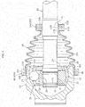
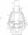
- FIG. 3 is an illustration of a constant velocity universal joint (fixed type constant velocity universal joint of a Barfield-type) according to the present invention.
- the constant velocity universal joint comprises an outer joint member 23, an inner joint member 26, a plurality of balls 27, and a cage 28.
- the outer joint member 23 has a plurality of track grooves 21, which are formed in a radially inner surface 22 at equal intervals along a circumferential direction of the outer joint member 23 and extend in an axial direction of the outer joint member 23.
- the inner joint member 26 has a plurality of track grooves 24, which are formed in a radially outer surface 25 of the inner joint member 26 at equal intervals along the circumferential direction and extend in the axial direction.
- the plurality of balls 27 are interposed between the track grooves 21 of the outer joint member 23 and the track grooves 24 of the inner joint member 26 and serve as torque transmission members configured to transmit torque.
- the cage 28 is interposed between the radially inner surface 22 of the outer joint member 23 and the radially outer surface 25 of the inner joint member 26 and is configured to retain the balls 27.
- a female spline 29 is formed along an inner periphery of an axial center hole of the inner joint member 26, and an end portion male spline 31 of a shaft 30 is fitted into the axial center hole of the inner joint member 26 so that the female spline 29 and the end portion male spline 31 are fitted to each other. Further, the end portion male spline 31 of the shaft 30 has a circumferential groove 32. A stop ring 33 serving as a stopper is mounted to the circumferential groove 32.
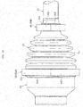
- the boot 35 comprises a large-diameter mounting portion (boot end portion) 35a, a small-diameter mounting portion (boot end portion) 35b, and a bellows portion 35c being a bent portion connecting the large-diameter mounting portion 35a and the small -diameter mounting portion 35b to each other.
- the boot material is a resin material mainly containing, for example, polyester-based, silicone-based, polyurethane-based, polyolefin-based, polyamide-based, polystyrene-based, vinyl-chloride-based, or fluorine-based thermoplastic elastomer.
- the boot material is a resin material mainly containing the polyester-based thermoplastic elastomer (thermoplastic polyester elastomer) being excellent in characteristics such as mechanical strength, heat resistance, oil resistance, and the like with respect to cost.
- the large-diameter mounting portion (one boot end portion) 35a of the boot 35 is mounted and fixed to a receiving surface (receiving surface of a mating member made of metal) 40 of a radially outer surface of the outer joint member 23 on an opening side, and the small-diameter mounting portion (another boot end portion) 35b is mounted and fixed to a radially outer surface (receiving surface of a mating member made of metal) 41 of a large-diameter portion of the shaft 30.
- first high-frequency induction heating coils 50 (50A and 50B) are used.
- radially outer surfaces 45A and 45B being non-mounting surfaces of the boot end portions 35a and 35b are tapered surfaces 51A and 51B each reduced in diameter from the boot bellows portion side toward the boot end portion side, that is, tapered surfaces each reduced in diameter from the boot inner side toward the boot outer side.
- the tapered surfaces 51A and 51B each have an inclination angle ⁇ set to from about 5° to about 30°.
- the high-frequency induction heating coils 50 are ring members, and radially inner surfaces 50Aa and 50Ba of the high-frequency induction heating coils 50 are tapered surfaces 52A and 52B each reduced in diameter from the boot bellows portion side toward the boot end portion side.
- the tapered surfaces 52A and 52B each have an inclination angle ⁇ 1 set to from about 5° to about 30°.
- the high-frequency induction heating coils 50A and 50B are each formed of copper wires or the like having conductivity and may be solid members or hollow members. When the high-frequency induction heating coils 50A and 50B are the hollow members, coolant water can pass therein. When the high-frequency induction heating coils 50A and 50B are the solid members, separate cooling jackets may be provided to the high-frequency induction heating coils 50A and 50B.
- FIG. 2A description is made of the outer joint member 23 side.
- the one boot end portion 35a is fitted over the receiving surface 40 being a boot receiving portion of the outer joint member 23.
- the high-frequency induction heating coil 50A is fitted into the one boot end portion 35a from the non-opening portion side of the outer joint member 23.
- an inner diameter dimension DA of the coil 50A on a downstream side in the fitting direction is larger, and an outer diameter dimension Da of the boot end portion 35a on an upstream side in the fitting direction is smaller. That is, DA>Da is satisfied, and such a setting enables smooth fitting.
- a minimum inner diameter dimension of the high-frequency induction heating coil 50A is larger in diameter than a maximum outer diameter of the outer joint member 23.
- the other boot end portion 35b is fitted over the receiving surface 41 being the boot receiving portion of the shaft 30.
- the high-frequency induction heating coil 50B is fitted into the other boot end portion 35b from the non-constant velocity universal joint side.
- an inner diameter dimension DB of the coil 50B on the downstream side in the fitting direction is larger, and an outer diameter dimension Db of the boot end portion 35b on the upstream side in the fitting direction is smaller. That is, DB>Db is satisfied, and such a setting enables smooth fitting.
- a minimum inner diameter dimension of the high-frequency induction heating coil 50B is larger in diameter than a maximum outer diameter of the shaft 30.
- the high-frequency induction heating coils 50 (50A and 50B) are set as illustrated in FIG. 1 .
- a high-frequency current is applied to the coils 50A and 50B.
- electromagnetic induction causes metal being conductive members (receiving surface 40 of outer joint member 23 and receiving surface 41 of shaft 30) to generate heat through core loss (sum of eddy current loss and hysteresis loss) .
- the heat causes a boundary portion of resin (mounting surface 53A of one boot end portion 35a and mounting surface 53B of another boot end portion 35b) in contact with the metal (receiving surface 40 of outer joint member 23 and receiving surface 41 of shaft 30) to be rapidly heated to a temperature equal to or higher than a decomposition temperature, and then the boundary portion is decomposed, thereby generating bubbles.
- high-temperature and high-pressure conditions are given to the high-temperature melt in the periphery of the above-mentioned bubbles and to the surface of the metal (receiving surface 40 of outer joint member 23 and receiving surface 41 of shaft 30).
- joined portions 55 and 56 are obtained between the mounting surface 53A of the one end portion 35a of the boot 35 and the receiving surface 40 of the outer joint member 23 and between the mounting surface 53B of the other end portion 35b of the boot 35 and the receiving surface 41 of the shaft 30.
- the mounting surface 53A of the boot end portion 35a and the receiving surface 40 of the outer joint member 23 are integrally joined to each other, and the mounting surface 53B of the boot end portion 35b and the receiving surface 41 of the shaft 30 are integrally joined to each other, thereby being capable of mounting and fixing the boot end portion 35a to the outer joint member 23 and mounting and fixing the boot end portion 35b to the shaft 30.
- FIG. 4 is an illustration of second high-frequency induction heating coils 50A and 50B.
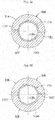
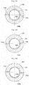
- the second high-frequency induction heating coils 50A and 50B comprise dividable ring members comprising a combined pair of arcuate members 60A and 60A and a combined pair of arcuate members 60B and 60B. Therefore, radially outer surfaces 45A and 45B of the boot end portions 35a and 35b (see FIG. 6 ) are formed into cylindrical surfaces 61A and 61B.
- the arcuate members 60A and 60A can be mounted (set) to the outer joint member 23 from a radially outer direction, and the arcuate members 60B and 60B can be mounted (set) to the shaft 30 from the radially outer direction.
- FIG. 5 is a sectional view for illustrating a state in which the high-frequency induction heating coil 50B is mounted to the mounting surface 53B of the boot end portion 35b and the receiving surface 41 of the shaft 30.
- the arcuate members 60B and 60B each have a semi-circular shape.
- the high-frequency induction heating coils 50A and 50B of the dividable type can be mounted (set) from the radially outer direction after the boot 35 is mounted to the outer joint member 23 and the shaft 30.
- the mounting surface 53A of the boot end portion 35a and the receiving surface 40 of the outer joint member 23 are integrally joined to each other, and the mounting surface 53B of the boot end portion 35b and the receiving surface 41 of the shaft 30 are integrally joined to each other, thereby being capable of mounting and fixing the boot end portion 35a to the outer joint member 23, and mounting and fixing the boot end portion 35b to the shaft 30, as illustrated in FIG. 6 .
- the boot end portions 35a and 35b are present (interposed) between the high-frequency induction heating coils 50A and 50B and the heated objects (mating members).
- the boot material is rubber or resin and is a non-conductive material. Therefore, even when the high-frequency induction heating coils 50A and 50B and the boot end portions 35a and 35b are brought into contact with each other, the high-frequency induction heating coils 50A and 50B are prevented from being broken. Further, the thickness of the boot end portions 3 5a and 35b is generally constant.
- the gaps formed between the mating members (outer joint member 23 and shaft 30) being heated objects and the high-frequency induction heating coils 50A and 50B can be maintained accurately in the circumferential direction. Therefore, the adhesive strength (joining strength) in the circumferential direction is uniform, thereby achieving the stable joining strength. Further, relative movement between the mating members (outer joint member 23 and shaft 30) and the high-frequency induction heating coils 50A and 50B is not required. Therefore, is possible to reduce the size and weight of the high-frequency induction heating device which comprises the high-frequency induction heating coils 50A and 50B, thus contributing to reduction in cost.
- the mounting surfaces 53A and 53B of the boot end portions 35a and 35b and the receiving surfaces 40 and 41 of the mating members (outer joint member 23 and shaft 30) have an interference corresponding to a diameter ratio of from 0.995 to 0.98.
- the interference is equal to or more than 0.995, a microscopic contact is poor between the metal (outer joint member 23 and shaft 30) and the boot material.
- the interference is larger than 0.98, the press-fit resistance of the boot 35 is large, with the result that there is a fear in that assembly is hindered.
- the contact strength can be increased. With this action, more stable joining strength can be obtained.
- the tapered surfaces 51A, 51B, 52A, and 52B each have a taper angle set to from 5° to 30° based on the moldability of the boot 35.
- the taper angle is less than 5°, the ease of fitting is degraded.
- the taper angle is more than 30°, the gaps of the high-frequency induction heating coils 50A and 50B with respect to the heated portions may significantly differ at axial end portions. Therefore, there is a fear in that the surface temperature of the mating members may vary.
- the contact between the radially inner surfaces 50Aa and 50Ba and the radially outer surfaces 45A and 45B being the non-mounting surfaces of the boot end portions 35a and 35b have an interference. Even a small interference in the boot 35 may stabilize the gap amount of the joined portions in the circumferential direction. Further, when the interference is excessively large, the high-frequency induction heating coils 50A and 50B cannot be fully closed, with the result that the function cannot be achieved, that is, the high-frequency induction heating coils 50A and 50B cannot be constructed. Therefore, in this case, it is preferred that the interference be from 0.05 mm to 0.3 mm.
- the inner diameter difference may be from 0 mm to 0.3 mm.
- third high-frequency induction heating coils 50 (50A and 50B) are used.
- the high-frequency induction heating coils 50A and 50B comprise the dividable ring members comprising the combined pair of arcuate members 60A and 60A and the combined pair of arcuate members 60B and 60B.
- Radially inner surfaces 50Aa and 50Ba and radially outer surfaces 50Ab and 50Bb of the high-frequency induction heating coils 50A and 50B are formed into cylindrical surfaces as illustrated in FIG. 8A, FIG. 8B , FIG. 9A, and FIG. 9B . Therefore, as illustrated in FIG. 6 , the radially outer surfaces 45A and 45B of the boot end portions 35a and 35b are formed into cylindrical surfaces.
- the arcuate members 60A and 60A are formed into rings by bringing joined surfaces thereof into abutment against each other.
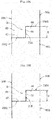
- mating surfaces of the arcuate members 60A and 60A (60B and 60B) each have the stepped structure M.
- both end surfaces of each of the arcuate members 60A and 60A (60B and 60B) serve as abutment surfaces.
- any one of the abutment surfaces which are opposed to (brought into abutment against) each other, has a protruding portion 66 and a recessed portion 67, and another of the abutment surfaces has a recessed portion 68, which is fitted to the protruding portion 66, and a protruding portion 69, thereby forming the stepped structure M.
- the stepped structure M has a step difference D of, for example, from about 3.0 mm to about 4.0 mm.
- the high-frequency induction heating coils 50A and 50B are each formed of copper wires or the like having conductivity and may be solid members or hollow members. When the high-frequency induction heating coils 50A and 50B are the hollow members, coolant water can pass therein. When the high-frequency induction heating coils 50A and 50B are the solid members, it is preferred that the separate cooling jackets be provided to the high-frequency induction heating coils 50A and 50B.
- FIG. 7 to FIG. 10A and FIG. 10B description is made of a boot mounting method using the third high-frequency induction heating coils 50 (50A and 50B) illustrated in FIG. 7 to FIG. 10A and FIG. 10B .
- the outer joint member 23 side In this case, the one boot end portion 35a (see FIG. 6 ) is fitted over the receiving surface 40 (see FIG. 6 ) being the boot receiving portion of the outer joint member 23.
- the abutment surfaces of the pair of arcuate members 60A and 60A are brought into abutment against each other from a radially outer side of the boot end portion 35a, thereby fitting the high-frequency induction heating coil 50A over the boot end portion 35a.
- the other boot end portion 35b (see FIG. 6 ) is fitted over the receiving surface 41 (see FIG. 6 ) being the boot receiving portion of the shaft 30.
- the abutment surfaces of the pair of arcuate members 60B and 60B are brought into abutment against each other from a radially outer side of the boot end portion 35b, thereby fitting the high-frequency induction heating coil 50B over the boot end portion 35b.
- the heat causes a boundary portion of resin (mounting surface 53A of one boot end portion 35a and mounting surface 53B of another boot end portion 35b) in contact with the metal (receiving surface 40 of outer joint member 23 and receiving surface 41 of shaft 30) to be rapidly heated to a temperature equal to or higher than a decomposition temperature, and then the boundary portion is decomposed, thereby generating bubbles.
- high-temperature and high-pressure conditions are given to the high-temperature melt in the periphery of the above-mentioned bubbles and to the surface of the metal (receiving surface 40 of outer joint member 23 and receiving surface 41 of shaft 30).
- the joined portions 55 and 56 are obtained between the mounting surface 53A of the one end portion 35a of the boot 35 and the receiving surface 40 of the outer joint member 23 and between the mounting surface 53B of the other end portion 35b of the boot 35 and the receiving surface 41 of the shaft 30.
- the pair of mating portions 70A1 and 70A2 (70B1 and 70B2), which extend in the axial direction, and a mating portion 71A (71B), which is continuously provided from the mating portions 70A1 and 70A2 (70B1 and 70B2) and extends in the circumferential direction.
- the pair of matingportions 70A1 and 70A2 (70B1 and 70B2) are different in phases, that is, different in positions in the circumferential direction.
- FIG. 11 is an illustration of a fixed portion between the boot end portion 35b and the shaft 30. Even at the fixed portion between the boot end portion 35a and the outer joint member 23, when the gap is formed among the mating portions 70A1, 70A2, and 71A, such a weak joined portion S1 and a rigid joined portion S are formed.
- the weak joined portion S1 and the rigid joined portion S are formed, the weak joined portion S1 has a stepped shape and forms a so-called labyrinth structure. Therefore, the sealing function capable of achieving functions of preventing entry of foreign matters such as dust into the joint or preventing leakage of grease sealed in the joint can be achieved.
- any one of the abutment surfaces has the pair of protruding portions 66 and 66 and the recessed portion 67 formed between the protruding portions 66 and 66, and another of the abutment surfaces has the pair of recessed portions 68 and 68, which are fitted to the protruding portions 66 and 66, and the protruding portion 69, which is fitted to the recessed portion 67.
- the width dimensions are set so as to satisfy W2>W1.
- the stepped structure M has the step difference D of from about 3.0 mm to about 4.0 mm.
- the pair of mating portions 70A1 and 70A2 (70B1 and 70B2), which extend in the axial direction
- mating portions 71A1 and 71A2 (71B1 and 71B2), which are continuously provided from the mating portions 70A1 and 70A2 (70B1 and 70B2) and extend in the circumferential direction
- the mating portion 72A (72B), which connects the mating portions 71A1 and 71A2 (71B1 and 71B2) to each other and extends in the axial direction.
- the mating portions 70A1 and 70A2 (70B1 and 70B2) and the mating portion 72A (72B) are different in phases, that is, different in positions in the circumferential direction.
- FIG. 16 is an illustration of a fixed portion between the boot end portion 35b and the shaft 30.
- the weak joined portion S1 has the stepped shape and forms the so-called labyrinth structure. Therefore, the sealing function capable of achieving the functions of preventing entry of foreign matters such as dust into the joint or preventing leakage of grease sealed in the joint can be achieved. With a constant velocity universal joint using the above-mentioned boot mounting method, excellent sealability can be achieved for a long period of time.
- the mounting surfaces 53A and 53B of the boot end portions 35a and 35b and the receiving surfaces 40 and 41 of the mating members have an interference corresponding to a diameter ratio of from 0.995 to 0.98.
- the interference is equal to or more than 0.995, a microscopic contact is poor between the metal and the boot material.
- the interference is larger than 0.98, the press-fit resistance of the boot is large, with the result that there is a fear in that assembly is hindered.
- fifth high-frequency induction heating coils 50 (50A and 50B) are used.
- the radially outer surfaces 45A and 45B being the non-mounting surfaces of the boot end portions 35a and 35b are the tapered surfaces 51A and 51B each reduced in diameter from the boot bellows portion side toward the boot end portion side.
- the tapered surfaces 51A and 51B each have the inclination angle ⁇ set to from about 5° to about 30°.
- the high-frequency induction heating coils 50 comprise ring members, and heat-insulating materials 46A and 46B are provided to the radially inner surfaces 50Aa and 50Ba of the high-frequency induction heating coils 50 (50A and 50B) .
- Radially outer surfaces 46Aa and 46Ba of the heat-insulating materials 46A and 46B are formed into cylindrical surfaces, and radially inner surfaces 46Ab and 46Bb of the heat-insulating materials 46A and 46B are formed into tapered surfaces 47A and 47B each reduced in diameter from the boot bellows portion side toward the boot end portion side.
- the tapered surfaces 47A and 47B each have an inclination angle ⁇ 1 set to from about 5° to about 30°.
- the high-frequency induction heating coils 50A and 50B are each formed of copper wires or the like having conductivity and may be solid members or hollow members.
- the heat-insulating materials 46 may be of a general heat-insulating material such as ceramics, glass wool, ceramics fiber, cement plate, or silicone rubber.
- the heat-insulating materials be made of an inorganic material (inorganic compound) such as ceramics or glass wool having high heat resistance.
- the heat-insulating material may be formed of foams of the inorganic material having a high heat insulating property.
- the heat-insulating materials 46 (46A and 46B) are interposed to reduce transfer of heat to the high-frequency induction heating coils 50 (50A and 50B) because the heated objects (outer joint member 23 and shaft 30 being mating members) and the high-frequency induction heating coils 50 (50A and 50B) are not cooled.
- various thicknesses may be employed for the heat-insulating materials 46 (46A and 46B) in accordance with a material to be used. However, it is necessary to set a dimension which can reduce the transfer of heat to the high-frequency induction heating coils 50 (50A and 50B).
- FIG. 18A description is made of the outer joint member 23 side.
- the one boot end portion 35a is fitted over the receiving surface 40 being the boot receiving portion of the outer joint member 23.
- the high-frequency induction heating coil 50A is fitted into the one boot end portion 35a from the non-opening portion side of the outer joint member 23.
- the inner diameter dimension (inner diameter dimension of heat-insulating material) DA of the coil 50A on the downstream side in the fitting direction is larger, and the outer diameter dimension Da of the boot end portion 35a on the upstream side in the fitting direction is smaller. That is, DA>Da is satisfied, and such a setting enables smooth fitting.
- the other boot end portion 35b is fitted over the receiving surface 41 being the boot receiving portion of the shaft 30.
- the high-frequency induction heating coil 50B is fitted into the other boot end portion 35b from the non-constant velocity universal joint side.
- the inner diameter dimension (inner diameter dimension of heat-insulating material) DB of the coil 50B on the downstream side in the fitting direction is larger, and the outer diameter dimension Db of the boot end portion 3 5b on the upstream side in the fitting direction is smaller. That is, DB>Db is satisfied, and such a setting enables smooth fitting.
- the high-frequency induction heating coils 50 (50A and 50B) are set as illustrated in FIG. 17 .
- a high-frequency current is applied to the coils 50A and 50B.
- electromagnetic induction causes metal being conductive members (receiving surface 40 of outer joint member 23 and receiving surface 41 of the shaft 30) to generate heat through core loss (sum of eddy current loss and hysteresis loss) .
- the heat causes a boundary portion of resin (mounting surface 53A of one boot end portion 35a (see FIG. 18A ) and mounting surface 53B of another boot end portion 35b (see FIG.
- the mounting surface 53A of the boot end portion 35a (see FIG. 18A ) and the receiving surface 40 of the outer joint member 23 are integrally joined to each other, and the mounting surface 53B of the boot end portion 35b (see FIG. 18B ) and the receiving surface 41 of the shaft 30 are integrally joined to each other, thereby being capable of mounting and fixing the boot end portion 35a to the outer joint member 23 and mounting and fixing the boot end portion 35b to the shaft 30.
- FIG. 19 is an illustration of sixth high-frequency induction heating coils 50A and 50B.
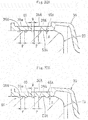
- the sixth high-frequency induction heating coils 50A and 50B comprise the dividable ring members comprising the combined pair of arcuate members 60A and 60A and the combined pair of arcuate members 60B and 60B. Therefore, the radially outer surfaces 45A and 45B of the boot end portions 35a and 35b are formed into the cylindrical surfaces 61A and 61B (see FIG. 6 ). Also in this case, as illustrated in FIG. 20A and FIG. 20B , the heat-insulating materials 48A and 48B are provided to the radially inner surfaces of the high-frequency induction heating coils 50A and 50B, respectively.
- the heat-insulating material 48A comprises a pair of semi-arcuate members 49A and 49A
- the heat-insulating material 48B comprises a pair of semi-arcuate members 49B and 49B.
- the semi-arcuate members 49A, 49A, 49B, and 49B are provided to the arcuate members 60A, 60A, 60B, and 60B.
- radially outer surfaces 48Aa and 48Ba and radially inner surfaces 48Ab and 48Bb of the heat-insulating materials 48A and 48B are formed into cylindrical surfaces.
- the arcuate members 60A and 60A can be mounted (set) to the outer joint member 23 from the radially outer direction, and the arcuate members 60B and 60B can be mounted (set) to the shaft 30 from the radially outer direction.
- the mounting surface 53A of the boot end portion 35a (see FIG. 6 ) and the receiving surface 40 of the outer joint member 23 (see FIG. 6 ) are integrally joined to each other, and the mounting surface 53B of the boot end portion 35b (see FIG. 6 ) and the receiving surface 41 of the shaft 30 (see FIG. 6 ) are integrally joined to each other, thereby being capable of mounting and fixing the boot end portion 35a to the outer joint member 23, and mounting and fixing the boot end portion 35b to the shaft 30, as illustrated in FIG. 6 .
- the boot end portions 35a and 35b are present (interposed) between the high-frequency induction heating coils 50A and 50B and the heated objects (mating members).
- the boot material is resin and is a non-conductive material. Therefore, even when the high-frequency induction heating coils 50A and 50B and the boot end portions 35a and 35b are brought into contact with each other through intermediation of the heat-insulating materials 46A and 46B, the high-frequency induction heating coils 50A and 50B are prevented from being broken. Further, the thickness of the boot end portions 35a and 35b is generally constant.
- the gaps formed between the mating members being the heated objects and the high-frequency induction heating coils 50A and 50B can be maintained accurately in the circumferential direction.
- the gaps formed between the mating members (outer joint member 23 and shaft 30) being the heated objects and the high-frequency induction heating coils 50A and 50B can be maintained accurately in the circumferential direction. Therefore, the adhesive strength (joining strength) in the circumferential direction is uniform, thereby achieving the stable joining strength. Further, relative movement between the mating members (outer joint member 23 and shaft 30) and the high-frequency induction heating coils 50A and 50B is not required, thereby being capable of reducing the size and weight of the high-frequency induction heating device which comprises the high-frequency induction heating coils 50A and 50B, thus contributing to reduction in cost.
- the heat-insulating materials 46A and 46B and the boot end portions 35a and 35b are present (interposed) between the high-frequency induction heating coils 50A and 50B and the heated objects (mating member), thereby being capable of suppressing the transfer of heat to the high-frequency induction heating coils 50A and 50B. Therefore, there are advantages in that the stable output and joining strength can be obtained even during continuous use and that longer lifetime of the coil can be achieved. Further, adhesion of the boot 35 and the high-frequency induction heating coils 50A and 50B caused by the rise in temperature of the coil can be prevented, thereby being excellent in operability.
- the mounting surfaces 53A and 53B of the boot end portions 35a and 35b and the receiving surfaces 40 and 41 of the mating members (outer joint member 23 and shaft 30) have an interference corresponding to a diameter ratio of from 0.995 to 0.98.
- the interference is less than 0.995, a microscopic contact is poor between the metal (outer joint member 23 and shaft 30) and the boot material.
- the interference is larger than 0.98, the press-fit resistance of the boot 35 is large, with the result that there is a fear in that assembly is hindered.
- the contact strength can be increased. With this action, more stable joining strength can be obtained.
- the tapered surfaces 47A, 47B, 51A, and 51B each have a taper angle set to from 5° to 30° based on the moldability of the boot 35.
- the taper angle is less than 5°, the ease of fitting is degraded.
- the taper angle is more than 30°, the gaps of the high-frequency induction heating coils 50A and 50B with respect to the heated portions may significantly differ at the axial end portions. Therefore, there is a fear in that the surface temperatures of the mating members may vary.
- the contact between the radially inner surfaces 46Ab and 46Bb of the heat-insulating materials 46A and 46B and the radially outer surfaces 45A and 45B being the non-mounting surfaces of the boot end portions 35a and 35b have an interference. Even a small interference in the boot 35 may stabilize the gap amount of the joined portions in the circumferential direction. Further, when the interference is excessively large, the high-frequency induction heating coils 50A and 50B cannot be fully closed, with the result that the function cannot be achieved, that is, the high-frequency induction heating coils 50A and 50B cannot be constructed. Therefore, in this case, it is preferred that the interference be from 0.05 mm to 0.3 mm.
- the inner diameter differences may be from 0 mm to 0.3 mm.
- FIG. 21 is an illustration of a case where seventh high-frequency induction heating coils 50 (50A and 50B) being the ring members are used.
- an inner diameter dimension of a radially inner surface 50Aa of the high-frequency induction heating coil 50A is set larger than an outer diameter dimension of the boot end portion 35a which is fitted over the receiving surface 40 of the outer joint member 23.
- the radially outer surface 45A of the boot end portion 35a has a circumferential recessed groove 36A, and a diameter dimension of a bottom surface of the circumferential recessed groove 36A corresponds to an outer diameter dimension of the boot end portion 35a.
- an inner diameter dimension of a radially inner surface 50Ba of the high-frequency induction heating coil 50B is set larger than an outer diameter dimension of the boot end portion 35b which is fitted over the receiving surface 41 of the shaft 30.
- the radially outer surface 45B of the boot end portion 35b has a circumferential recessed groove 36B, and a diameter dimension of a bottom surface of the circumferential recessed groove 3 6B corresponds to an outer diameter dimension of the boot end portion 35b.
- the radially inner surface of the high-frequency induction heating coil 50A be set larger than the maximum outer diameter of the boot 35. Further, it is preferred that the radially inner surface of the high-frequency induction heating coil 50A be set larger than the maximum outer diameter of the boot end portion 35b.
- the high-frequency induction heating coils 50A and 50B are each formed of copper wires or the like having conductivity and may be solid members or hollow members. When the high-frequency induction heating coils 50A and 50B are the hollow members, coolant water can pass therein. When the high-frequency induction heating coils 50A and 50B are solid members, the separate cooling jackets may be provided to the high-frequency induction heating coils 50A and 50B.
- the receiving surface 40 of the outer joint member 23 (receiving surface 41 of shaft 30) has a plurality of (five in the illustrated example) slits (recessed grooves) 38A and 38B extending in the circumferential direction.
- the slits 38A and 38B each have a semi-arcuate sectional shape.
- the slits 38A and 38B each have a depth dimension A being set within a range of from 0.1 mm to 1 mm and a width dimension W being set within a range of from 0.3 mm to 1 mm.
- An arrangement pitch P of the slits 38A and 38B is set within a range of from 1 mm to 10 mm.
- the slits 38A may be formed in the receiving surface 40 at the time of forging the outer joint member 23, or may be formed by turning.
- the slits 38B may be formed in the receiving surface 41 of the shaft 30 by turning, or may be formed by rolling.
- the values of A, W, and P may suitably be set in accordance with influence on strength of a member which is to be mounted, a width of the boot joined portion, and easiness in processing of a part which is to be mounted.
- FIG. 21 description is made of a boot mounting method using the high-frequency induction heating coils 50 (50A and 50B) illustrated in FIG. 21 .
- the outer joint member 23 side As illustrated in FIG. 22A , the one boot end portion 35a is fitted over the receiving surface 40 being the boot receiving portion of the outer joint member 23.
- the high-frequency induction heating coil 50A is loosely fitted over the outer peripheral side of the boot end portion 35a (see FIG. 21 ).
- the gap GA between the radially inner surface of the high-frequency induction heating coil 50A and the radially outer surface of the boot end portion 35a is set to about 2 mm.
- the other boot end portion 35b is fitted over the receiving surface 41 being the boot receiving portion of the shaft 30.
- the high-frequency induction heating coil 50B is loosely fitted over the outer peripheral side of the boot end portion 35b (see FIG. 21 ) .
- the gap GB between the radially inner surface of the high-frequency induction heating coil 50B and the radially outer surface of the boot end portion 35b is set to about 2 mm.
- the high-frequency induction heating coils 50 (50A and 50B) are set as illustrated in FIG. 21 .
- a high-frequency current is applied to the coils 50A and 50B.
- electromagnetic induction causes metal being conductive members (receiving surface 40 of outer joint member 23 and receiving surface 41 of shaft 30) to generate heat through core loss (sum of eddy current loss and hysteresis loss) .
- the heat causes a boundary portion of the boot material (mounting surface 53A of one boot end portion 35a and mounting surface 53B of another boot end portion 35b) in contact with the metal (receiving surface 40 of outer joint member 23 and receiving surface 41 of shaft 30) to be rapidly heated to a temperature equal to or higher than a decomposition temperature, and then the boundary portion of the boot material is decomposed, thereby generating bubbles.
- high-temperature and high-pressure conditions are given to the high-temperature melt in the periphery of the above-mentioned bubbles and to the surface of the metal (receiving surface 40 of outer joint member 23 and receiving surface 41 of shaft 30).
- the joined portions 55 and 56 are obtained between the mounting surface 53A of the one end portion 35a of the boot 35 and the receiving surface 40 of the outer joint member 23 and between the mounting surface 53B of the other end portion 35b of the boot 35 and the receiving surface 41 of the shaft 30.
- the mounting surface 53A of the boot end portion 35a and the receiving surface 40 of the outer joint member 23 are integrally joined to each other, and the mounting surface 53B of the boot end portion 35b and the receiving surface 41 of the shaft 30 are integrally joined to each other, thereby being capable of mounting and fixing the boot end portion 35a to the outer joint member 23 and mounting and fixing the boot end portion 35b to the shaft 30.
- the slits 38A and 38B are formed in the receiving surfaces 40 and 41 being the radially outer surfaces of the mating members. Therefore, the boot material melted by the high-frequency induction heating enters the slits 38A and 38B. That is, the boot material enters the space formed in the receiving surfaces 40 and 41 and is hardened, thereby achieving the anchor effect (see FIG. 22B and FIG. 23B ).
- the joining strength between the boot end portions 35a and 35b and the mating members (outer joint member 23 and shaft 30) is increased by the anchor effect, thereby achieving the stable joining strength between the boot end portions 35a and 35b and the mating members (outer joint member 23 and shaft 30). Therefore, highly accurate sealing performance can be achieved also during rotation under the state in which the constant velocity universal joint takes the operating angle.
- edge portions are formed.
- the proximity effect of the electromagnetic induction causes the edge portions to be more likely to raise its temperature, and a desired temperature is likely to be obtained in a wide range, thereby being capable of improving the operability.
- relative movement between the mating members (outer joint member 23 and shaft 30) and the high-frequency induction heating coils 50A and 50B is not required, thereby being capable of reducing the size and weight of the high-frequency induction heating device which comprises the high-frequency induction heating coils 50A and 50B, thus contributing to reduction in cost.
- FIG. 25 is an illustration of the seventh high-frequency induction heating coils 50A and 50B.
- the seventh high-frequency induction heating coils 50A and 50B comprise the dividable ring members comprising the combined pair of arcuate members 60A and 60A and the combined pair of arcuate members 60B and 60B.
- the arcuate members 60A and 60A can be mounted (set) to the outer joint member 23 from the radially outer direction, and the arcuate members 60B and 60B can be mounted (set) to the shaft 30 from the radially outer direction.
- the radially inner surfaces 50Aa and 50Ba of the high-frequency induction heating coils 50A and 50B are brought into contact with the non-mounting surfaces 45A and 45B being the radially outer surfaces of the boot end portions 35a and 35b at both the end portions of the boot 35.
- the mounting surface 53A of the boot end portion 35a (see FIG. 24 ) and the receiving surface 40 of the outer joint member 23 (see FIG. 24 ) are integrally joined to each other, and the mounting surface 53B of the boot end portion 35b (see FIG. 24 ) and the receiving surface 41 of the shaft 30 (see FIG. 24 ) are integrally joined to each other, thereby being capable of mounting and fixing the boot end portion 35a to the outer joint member 23, and mounting and fixing the boot end portion 35b to the shaft 30.
- the slits 38A and 38B are formed in the receiving surface 40 of the outer joint member 23 and the receiving surface 41 of the shaft 30. Therefore, even with the high-frequency induction heating coils 50A and 50B of the separable type illustrated in FIG. 25 , the action and effect which are similar to those of the mounting method using the high-frequency induction heating coils 50A and 50B of the non-separable type illustrated in FIG. 21 can be achieved.
- the boot end portions 35a and 35b are present (interposed) between the high-frequency induction heating coils 50A and 50B and the heated objects (mating members).
- the boot material is resin and is a non-conductive material. Therefore, even when the high-frequency induction heating coils 50A and 50B and the boot end portions 35a and 35b are brought into contact with each other, the high-frequency induction heating coils 50A and 50B are prevented from being broken. Further, the thickness of the boot end portions 35a and 35b is generally constant.
- the gaps formed between the mating members being the heated objects and the high-frequency induction heating coils 50A and 50B can be maintained accurately in the circumferential direction.
- the gaps formed between the mating members (outer joint member 23 and shaft 30) being the heated objects and the high-frequency induction heating coils 50A and 50B can be maintained accurately in the circumferential direction. Therefore, the adhesive strength (joining strength) in the circumferential direction is uniform, thereby achieving the stable joining strength. Further, relative movement between the mating members (outer joint member 23 and shaft 30) and the high-frequency induction heating coils 50A and 50B is not required, thereby being capable of reducing the size and weight of the high-frequency induction heating device which comprises the high-frequency induction heating coils 50A and 50B, thus contributing to reduction in cost.
- the mounting surfaces 53A and 53B of the boot end portions 35a and 35b and the receiving surfaces 40 and 41 of the mating members (outer joint member 23 and shaft 30) have an interference corresponding to a diameter ratio of from 0.995 to 0.98.
- the interference is equal to or more than 0.995, a microscopic contact is poor between the metal (outer joint member 23 and shaft 30) and the boot material.
- the interference is larger than 0.98, the press-fit resistance of the boot 35 is large, with the result that there is a fear in that assembly is hindered.
- the contact between the radially inner surfaces 50Aa and 50Ba and the radially outer surfaces 45A and 45B being the non-mounting surfaces of the boot end portions 35a and 35b have an interference (see FIG. 6 ). Even a small interference in the boot 35 may stabilize the gap amount of the joined portions in the circumferential direction. Further, when the interference is excessively large, the high-frequency induction heating coils 50A and 50B cannot be fully closed, with the result that the function cannot be achieved, that is, the high-frequency induction heating coils 50A and 50B cannot be constructed. Therefore, in this case, it is preferred that the interference be from 0.05 mm to 0.3 mm.
- FIGS. 27 are illustrations of modification examples of the slits 38.
- each slit 38 has a rectangular sectional shape. That is, the slits 38 illustrated in FIG. 21 and FIG. 27A each have a start end and a terminal end matching with each other and are each formed of a circumferential recessed groove.
- the slits illustrated in FIG. 27B are each a spiral groove having a start end and a terminal end different from each other.
- FIG. 27A and FIG. 27B are illustrations of the receiving surface 41 of the shaft 30.
- the slits 38 having such a shape may be formed in the receiving surface 40 of the outer joint member 23.
- the boot material be thermoplastic polyester-based elastomer.
- the thermoplastic polyester-based elastomer is excellent in mechanical strength, moldability, and elasticity, and hence is preferred as a material providing functions such as bending resistance required for the boot. Further, the thermoplastic polyester-based elastomer is less liable to be thermally deformed and has high heat-resistant temperature. Therefore, when this material is applied to the boot which is exposed to high temperature such as during an operation of the constant velocity universal joint, degradation of the durability of the boot due to high temperature can be prevented.
- the decomposition temperature of the thermoplastic polyester-based elastomer is from about 400°C to about 500°C, which is a temperature range being likely to be obtained through the electromagnetic induction heating. Therefore, the thermoplastic polyester-based elastomer is most suitable for use as the boot material in the boot mounting method.
- the high-frequency induction heating is used on both the outer joint member side and the shaft side without use of the boot band.
- any one of the outer joint member side and the shaft side may be subjected to the known mounting and fixing method using the boot band.
- boot end portions 35a and 35b and the high-frequency induction heating coils 50A and 50B may be brought into contact with each other or may be prevented from being brought into contact with each other.
- the gap between the heated object (mating member) and the coil be uniform over an entire periphery in the circumferential direction. Therefore, it is preferred that the boot end portions 35a and 35b and the high-frequency induction heating coils 50A and 50B be brought into contact with each other
- both the boot end portions 35a and 35b may be simultaneously mounted.
- a process of mounting one of the boot end portions 35a and 35b may be performed first and after the process, a process of mounting another of the boot end portions 35a and 35b may be performed.
- a thickness dimension of the heat-insulating material 38 may suitably be set. However, it is necessary to set the thickness dimension so as to prevent insufficient heating of the mating member due to an excessively large gap between the mating member being the heated object and the high-frequency induction heating coils 50A and 50B.
- each slit formed in the receiving surface match with each other, the number of slits and arrangement pitches of the slits may suitably be set. For example, unequal pitches may be set. Further, even in the case of the spiral groove illustrated in FIG. 27(b) , the number of turns may suitably be set.
- the sectional shape of each slit is not limited to the semi-arcuate shape or the rectangular shape, and may be a triangular shape, a semi-polygonal shape, a semi-oval shape, or the like. However, these slits also need to be formed so as to allow entry and hardening of the boot material, achieve the anchor effect, and be likely to obtain a desired temperature in a wide range with the proximity effect of the induction heating.
- Table 1 and Table 2 are record tables with regard to an interference between an inner diameter (diameter) of the boot end portion and an outer diameter (diameter) of the receiving surface of the mating member.
- connection between the boot end portion (mounting portion) 35b and the shaft 30 is shown, in a case in which an inner diameter dimension of the boot end portion (mounting portion) 35b is 22 mm (diameter).
- connection between the boot end portion (mounting portion) 35a and the outer joint member (outer ring) 23 is shown, in a case in which an inner diameter dimension of the boot end portion (mounting portion) 35a is 70 mm (diameter).
- the comprehensive evaluation of "excellent” is denoted by ⁇ .
- the comprehensive evaluation of "good” is denoted by ⁇ .
- the comprehensive evaluation of "acceptable” is denoted by ⁇ .
- the comprehensive evaluation of "not acceptable” is denoted by ⁇ .
- the inner diameter of the mounting surface of the boot end portion and the outer diameter of the receiving surface of the mating member have an interference corresponding to the diameter ratio of from 0.995 to 0.98. That is, the comprehensive evaluations of ⁇ and ⁇ are given in this range.
- the straight mating surface having no stepped structure caused leakage after 50 hours.
- the labyrinth 1 did not cause leakage after operation for 70 hours.
- the labyrinth 2 did not cause leakage after operation for 85 hours.
- the fixed type constant velocity universal joint is not limited to the illustrated example, and may be a fixed type constant velocity universal joint of an undercut-free type, or a plunging type constant velocity universal joint of a double-offset type, cross-groove type, or a tripod type.
Landscapes
- Engineering & Computer Science (AREA)
- General Engineering & Computer Science (AREA)
- Mechanical Engineering (AREA)
- Physics & Mathematics (AREA)
- Thermal Sciences (AREA)
- Diaphragms And Bellows (AREA)
- General Induction Heating (AREA)
Abstract
Description
- The present invention relates to a boot mounting method for a constant velocity universal joint, and to a constant velocity universal joint which is constructed using the boot mounting method.
- For a constant velocity universal joint which is to be assembled to, for example, a power transmission mechanism of automobiles and various industrial machines, a boot (boot for a constant velocity universal joint) is mounted for the purpose of preventing entry of foreign matters such as dust into the joint and preventing leakage of grease sealed in the joint.
- As illustrated in
FIG. 28 , a constant velocity universal joint (fixed type constant velocity universal joint) includes anouter joint member 3, aninner joint member 6, a plurality of balls 7, and acage 8. Theouter joint member 3 has a plurality oftrack grooves 1, which are formed in a radially inner surface 2 and extend in an axial direction. Theinner joint member 6 has a plurality of track grooves 4, which are formed in a radially outer surface 5 at equal intervals along a circumferential direction and extend in the axial direction. The plurality of balls 7 are interposed between thetrack grooves 1 of theouter joint member 3 and the track grooves 4 of theinner joint member 6 and are configured to transmit torque . Thecage 8 is interposed between the radially inner surface 2 of theouter joint member 3 and the radially outer surface 5 of theinner joint member 6 and is configured to retain the balls 7. - A
female spline 9 is formed along an inner periphery of an axial center hole of theinner joint member 6, and an end portionmale spline 11 of ashaft 10 is fitted into the axial center hole of theinner joint member 6 so that thefemale spline 9 and the end portionmale spline 11 are fitted to each other. Further, the end portionmale spline 11 of theshaft 10 has acircumferential groove 12. Astop ring 13 serving as a stopper is mounted to thecircumferential groove 12. - An opening portion of the
outer joint member 3 is sealed with aboot 15. Theboot 15 includes a large-diameter mounting portion 15a, a small-diameter mounting portion 15b, and abellows portion 15c connecting the large-diameter mounting portion 15a and the small-diameter mounting portion 15b to each other. The large-diameter mounting portion 15a of theboot 15 is fastened and fixed by afastening band 16 at an opening end of theouter joint member 3, and the small-diameter mounting portion of theboot 15 is fastened and fixed by afastening band 17 at a predetermined portion of theshaft 10. - There has been known a lever type boot band (Patent Literature 1) as such a fastening band. Specifically, the lever type boot band includes a band main body and a lever. The band main body is formed on a ring portion. The lever is provided to a joined portion of the band main body. The lever is folded back so that an inner surface of the lever overlaps a radially outer surface of the band main body.
- Further, as the fastening band, there has been known a fastening band using an engagement claw and an engagement hole (Patent Literature 2). According to the fastening band disclosed in Patent Literature 2, an ear portion protruding radially outward is formed, and the ear portion is compressed to reduce a diameter of a ring portion.
- However, when such a band is used, it is necessary to use the band as a separate component, and the number of components is increased. As a result, manufacture cost required for assembly of the constant velocity universal joint is increased. Further, under a state in which the band is mounted, it is necessary to highly accurately fasten the band with a predetermined interference in order to secure sealability. However, there is difficulty in achieving highly accurate fastening while dealing with variation in individuals.
- Therefore, there have hitherto been proposed methods of mounting and fixing a boot end portion to a mating member using high-frequency induction (Patent Literature 3) or laser light (Patent Literature 4) without use of the fastening band (boot band) .
- According to the method using the high-frequency induction, under a state in which a boot end portion is fitted over a receiving surface of a mating member, a high-frequency induction heating coil is arranged on an outer peripheral portion of the boot end portion, and a high-frequency current is applied to the high-frequency induction heating coil. Specifically, the receiving surface of the mating member having conductivity is heated by high-frequency waves through the boot end portion, with the result that the boot end portion and the receiving surface of the mating member are joined and integrated to each other by the heat.
- Further, according to the method using the laser light, a metal material and a resin material are joined to each other by a physical interaction caused by irradiation of laser light from a resin material surface side.
-
- Patent Literature 1:
JP 2011-252594 A - Patent Literature 2:
JP 2004-510113 A - Patent Literature 3:
JP 2009-52688 A - Patent Literature 4:
JP 2009-185879 A - With the method using the high-frequency induction, as compared to the related-art fastening method using the band, there are advantages in that the number of components can be reduced and that assembly of the constant velocity universal joint can be simplified. Incidentally, the electromagnetic induction heating with high-frequency waves is generally used in, for example, heat treatment for metal. This heating method involves self-heating through use of an induced current generated in a heated object. Therefore, only a material having conductivity can be heated, and a non-conductive material is not heated.
- At the time of heating, a clearance (gap) needs to be formed between the coil and the heated object. This is because the coil is damaged when the coil that is electrified is brought into contact with the heated object. Further, rapid heating and surface heating can be performed through use of the high-frequency induction, and a heating temperature is changed in accordance with an oscillation frequency, a current, and a distance (gap amount) between the coil and the heated object.
- Therefore, in order to mount and fix the boot by the high-frequency induction heating, it is necessary to arrange the high-frequency induction heating coil so as to be coaxial with a shaft or an outer joint member. Specifically, this is because, when the gap amount between the coil and the shaft or between the coil and the outer joint member is not uniform in any phase in the circumferential direction, surface temperatures in respective phases may vary, with the result that the joining strength may also vary. However, there is difficulty in arranging the coil so as to be coaxial with the shaft or the outer joint member with high accuracy, and there is a fear in that a uniform gap amount cannot be set.
- Further, the electromagnetic induction heating often causes the rise in temperature of the coil itself by transferred heat or radiant heat from the heated object. Therefore, when the electromagnetic induction heating is used in heat treatment for metal, the coil is also cooled together with the heated object by a coolant or the like, with the result that accumulation of heat in the coil due to the transferred heat or the radiant heat from the heated object is cancelled.
- However, when a boot is mounted to a constant velocity universal joint, a heated object (outer joint member or shaft) and a coil are not cooled. Therefore, there is a fear in that a stable output of the coil is less likely to be obtained or that the lifetime of the coil is shortened.
- Further, the method using the laser light requires a laser irradiation device, and it is necessary to irradiate the laser light to an irradiated portion over an entire periphery in a circumferential direction and over an entire length in an axial direction. Therefore, the device is complicated, with the result that the cost is increased.
- Further, when the high-frequency induction heating coil is used, it is preferred that a separated structure be employed in consideration of simplification of assembly steps.
- However, when the separated structure is employed, a mating surface is formed on the coil. When such a mating surface is formed, there is a fear in that a non-adhering portion or a portion having a smaller joining strength is formed in the joined portion corresponding to the mating surface.
- Incidentally, the fixing of the boot requires a joining strength, which can tolerate generation of a rotary force caused by a differential motion in a case of expansion and contraction of the boot or a contact with the bellows, and a function of preventing leakage from the boot. Therefore, consideration is made of the case where the non-adhering portion or the like is formed in the joined portion corresponding to the mating portion of the coil. The joining strength can be compensated through increase in a joining area. Meanwhile, with regard to the leakage of grease, the leakage of grease is more liable to occur when there is any phase in which the boot is not joined in the circumferential direction.
- Further, when the constant velocity universal joint is rotated in a state of taking an operating angle, a relatively large force is received at a joined portion between the boot and the outer joint member and at a joined portion between the shaft and the boot. Therefore, in the joining method for a boot through use of the electromagnetic induction heating, it is necessary to obtain a large joining strength at those joined portions.
- However, the receiving surface being the radially outer surface of the mating member is a cylindrical surface, and hence the method using the high-frequency induction cannot achieve an effect of causing an adhesive to enter a hole or a cleavage of a material surface and be hardened thereat (anchor effect) . Therefore, there is difficulty in obtaining a large joining strength.
- Accordingly, a first object of the present invention is to provide a boot mounting method which is capable of achieving a uniform adhesive strength (joining strength) in a circumferential direction and obtaining a stable joining strength, and to provide a constant velocity universal joint using the boot mounting method. A second object of the present invention is to provide a boot mounting method which prevents loss of sealability even when joining is performed under a state in which employment of a separable coil causes a gap formed between mating surfaces of the separable coil and in which portions corresponding to the joining surfaces are in non-contact state, and to provide a constant velocity universal joint using the boot mounting method. A third object of the present invention is to provide a boot mounting method which is capable of achieving a uniform adhesive strength (joining strength) in the circumferential direction to obtain a stable joining strength, achieving longer lifetime of the high-frequency induction heating coil which is to be used, and obtaining a stable output, and to provide a constant velocity universal joint by the boot mounting method. A fourth object of the present invention is to provide a boot mounting method which is capable of obtaining a stable and large joining strength, and to provide a constant velocity universal joint by the boot mounting method.
- There is provided a boot mounting method for a constant velocity universal joint in which a boot end portion is mounted and fixed to a mating member made of metal, the boot mounting method comprising: fitting the boot end portion over a receiving surface being a radially outer surface of the mating member; fitting a high-frequency induction heating coil having a ring shape over the boot end portion; and heating only a top portion of the receiving surface of the mating member by high-frequency induction through application of a high-frequency current to the high-frequency induction heating coil so that a mounting surface being a radially inner surface of the boot end portion and the receiving surface being the radially outer surface of the mating member are integrally joined to each other.
- With the boot mounting method according to the present invention, when a high-frequency current is applied to the high-frequency induction heating coil, the electromagnetic induction causes the mating member made of metal being a conductive member to generate heat through core loss (sum of eddy current loss and hysteresis loss). The heat causes a boundary portion of the boot end portion in contact with the mating member to be rapidly heated to a temperature equal to or higher than a decomposition temperature, and then the boundary portion of the boot end portion is decomposed, thereby generating bubbles. With this action, high-temperature and high-pressure conditions are given to the high-temperature melt in the periphery of the above-mentioned bubbles and to the surface of the mating member. As a result, the joined portion is obtained between the mounting surface of the boot end portion and the receiving surface of the mating member. With this action, the boot end portion is mounted and fixed to the mating member made of metal.
- With this method, the boot end portion is present (interposed) between the high-frequency induction heating coil and the heated object (mating member) . The boot material is resin, which is a non-conductive material. Therefore, even when the high-frequency induction heating coil and the boot end portion are brought into contact with each other, the high-frequency induction heating coil is prevented from being broken. Further, the thickness of the boot end portion is generally constant. Therefore, when the high-frequency induction heating coil is brought into contact with a radially outer portion (non-adhering surface) of the mounting surface of the boot end portion, a gap formed between the mating member being the heated object and the high-frequency induction heating coil can be maintained accurately in the circumferential direction.
- Further, the high-frequency induction heating coil having the ring shape may be fitted over the boot end portion under a state in which a heat-insulating material is interposed between an inner peripheral surface of the high-frequency induction heating coil and the boot end portion. When the heat-insulating material is interposed as described above, the heat-insulating material and the boot end portion are present (interposed) between the high-frequency induction heating coil and the heated object (mating member), thereby being capable of suppressing transfer of heat to the coil. Further, the boot material is resin, which is a non-conductive material. Therefore, even when the high-frequency induction heating coil is brought into contact with the boot end portion through intermediation of the heat-insulating material, the high-frequency induction heating coil is prevented from being broken. Further, the thickness of the boot end portion is generally constant. Therefore, when the high-frequency induction heating coil is brought into contact with the radially outer portion (non-adhering surface) of the mounting surface of the boot end port ion, a gap formed between the mating member being the heated object and the high-frequency induction heating coil can be maintained accurately in the circumferential direction.
- It is preferred that heating be performed by high-frequency induction under the state in which the non-mounting surface being the radially outer surface of the boot end portion and the radially inner surface of the heat-insulating material are held in contact with each other and in which the radially outer surface of the heat-insulating material and the radially inner surface of the high-frequency induction heating coil are held in contact with each other. Through such a contact, a gap between the high-frequency induction heating coil and the mated member can be set uniform over an entire periphery in the circumferential direction.
- The heat-insulating material may be a general heat-insulating material such as ceramics, glass wool, ceramics fiber, cement plate, or silicone rubber. However, it is preferred that the heat-insulating material be made of an inorganic compound (inorganic material) such as ceramics or glass wool having high heat resistance.
- A slit may be formed in the receiving surface being the radially outer surface of the mating member, and after the boot end portion is fitted over the receiving surface of the mating member, the high-frequency induction heating coil having the ring shape may be fitted over the boot end portion.
- As described above, when the slit is formed in the receiving surface being the radially outer surface of the mating member, the boot material melted by the high-frequency induction enters the slit. That is, the boot material enters a space formed in the receiving surface and is hardened therein, thereby achieving the anchor effect. Further, through formation of the slit in the receiving surface being a cylindrical surface, an edge portion is formed. The proximity effect of the electromagnetic induction causes the edge portion of the slit to be more likely to raise its temperature, and a desired temperature can be obtained over a wide range of the coil contact surface (boot joining surface).
- The slit formed in the receiving surface of the mating member may have a depth set within a range of from 0.1 mm to 1 mm. When the depth of the slit is more than 1 mm, the slit is excessively deep, with the result that the strength of the mating member (outer joint member or shaft) is degraded. Further, the electromagnetic induction is performed at high frequency for a short period of time. Therefore, there is a fear in that heating is less likely to be performed. In contrast, when the depth of the slit is less than 0.1 mm, the anchor effect of causing the boot material to enter the space formed in the receiving surface and be hardened therein is less likely to be achieved, and the proximity effect by the electromagnetic induction is less likely to be obtained.
- It is preferred that the high-frequency induction heating coil comprise a dividable ring member comprising two arcuate members combined with each other, and that a contact between the radially inner surface of the high-frequency induction heating coil and the radially outer surface being the non-mounting surface of the boot end portion have an interference. Even a small interference in the boot may stabilize the gap amount of the joined portion in the circumferential direction. Further, when the interference is excessively large, the coil cannot be fully closed, with the result that the function cannot be achieved, that is, the high-frequency induction heating coil cannot be constructed. Therefore, in this case, it is preferred that an interference of from 0.05 mm to 0.3 mm be set.
- Further, when the high-frequency induction heating coil is a dividable ring member, a small gap is formed between mating surfaces. Therefore, there is a fear in that the joined portions corresponding to the mating surfaces become non-joined portions with respect to the boot and the mating member or become a portion having a small joining strength. Therefore, each mating surface of the high-frequency induction heating coil has a stepped structure, and the non-joined portion or the portion having a small joining strength has a so-called labyrinth structure.
- The stepped structure may comprise: a protruding portion formed on the mating surface of one of the arcuate members; and a recessed portion, which is formed in the mating surface of another of the arcuate members and receives the protruding portion fitted to the recessed portion.
- In particular, it is preferred that a diameter (inner diameter) of the mounting surface of the boot end portion and a diameter (outer diameter) of the receiving surface of the mating member have an interference corresponding to a ratio of from 0.995 to 0.98. When the diameter ratio between the mounting surface of the boot end portion and the receiving surface of the mating member is less than 0.995 (smaller interference), a microscopic contact between the metal and the boot material is poor. When the interference is larger than 0.98 (larger interference), the press-fit resistance of the boot is large, with the result that there is a fear in that assembly is hindered.
- The high-frequency induction heating coil may comprise a non-dividable ring member, and the radially inner surface of the high-frequency induction heating coil and the radially outer surface being the non-mounting surface of the boot end portion each may have a tapered surface reduced in diameter from a boot bellows portion side toward a boot end portion side. With such setting, the side of the high-frequency induction heating coil, which is larger in diameter, can be fitted into the boot end portion from a small-diameter side of the boot end portion.
- The tapered surface may have a taper angle of from 5° to 30°. This is based on the moldability of the boot. When the taper angle is less than 5°, the ease of fitting is degraded. When the taper angle is more than 30°, a gap of the coil with respect to the heated portion significantly differs at an axial end portion. Therefore, there is a fear in that the surface temperature of the mating member may vary.
- It is preferred that the boot material be thermoplastic polyester-based elastomer. The thermoplastic polyester-based elastomer is excellent in mechanical strength, moldability, and elasticity, and hence is preferred as a material providing functions such as bending resistance required for the boot.
- According to one embodiment of the present invention, there is provided a first constant velocity universal joint, comprising: an outer joint member; an inner joint member; and a torque transmission member interposed between the outer joint member and the inner joint member, the outer joint member having an opening portion sealed with a boot, the boot comprising: a large-diameter mounting portion mounted to a boot receiving portion formed in a radially outer surface on the opening portion side of the outer joint member; a small-diameter mounting portion mounted to a boot receiving portion of a shaft fitted into the inner joint member; and a bent portion connecting the large-diameter mounting portion and the small-diametermounting portion, the large-diameter mounting portion of the boot being the boot end portion, the boot receiving portion formed in the radially outer surface of the outer joint member on the opening portion side being the receiving surface of the mating member, the large-diameter mounting portion of the boot and the boot receiving portion of the outer joint member being integrally joined to each other through use of the boot mounting method.
- According to one embodiment of the present invention, there is provided a second constant velocity universal joint, comprising: an outer joint member; an inner joint member; and a torque transmission member interposed between the outer joint member and the inner joint member, the outer joint member having the opening portion sealed with a boot, the boot comprising: a large-diameter mounting portion mounted to a boot receiving portion formed in a radially outer surface on an opening portion side of the outer joint member; a small-diameter mounting portion mounted to a boot receiving portion of a shaft fitted into the inner joint member; and a bent portion connecting the large-diameter mounting portion and the small-diameter mounting portion, the small-diameter mounting portion of the boot being the boot end portion, the boot receiving portion of the shaft being the receiving surface of the mating member, the small-diameter mounting portion of the boot and the boot receiving portion of the shaft being integrally joined to each other through use of the boot mounting method.
- According to the present invention, a gap formed between the mating member being the heated object and the high-frequency induction heating coil can be maintained accurately in the circumferential direction. Therefore, the adhesive strength (joining strength) in the circumferential direction is uniform, thereby achieving the stable joining strength. Further, relative movement between the mating member and the high-frequency induction heating coil is not required. Therefore, is possible to reduce the size and weight of the high-frequency induction heating device which comprises the high-frequency induction heating coil, thus contributing to reduction in cost.
- When the heat-insulating material is interposed, the heat-insulating material and the boot end portion are present (interposed) between the high-frequency induction heating coil and the heated object (mating member), thereby being capable of suppressing transfer of heat to the coil. Therefore, there are advantages in that the stable output and joining strength can be obtained even during continuous use and that longer lifetime of the coil can be achieved. Further, adhesion of the boot material and the coil caused by the rise in temperature of the coil can be prevented, thereby being excellent in operability.
- A gap formed between the mating member being the heated object and the high-frequency induction heating coil can be maintained accurately in the circumferential direction. Therefore, the adhesive strength (joining strength) in the circumferential direction is uniform, thereby achieving the stable joining strength. Further, relative movement between the mating member and the high-frequency induction heating coil is not required. Therefore, is possible to reduce the size and weight of the high-frequency induction heating device which comprises the high-frequency induction heating coil, thus contributing to reduction in cost.
- When the inorganic material (inorganic compound) is used as the heat-insulating material, excellent heat resistance and durability can be achieved.
- When the slit is formed in the receiving surface being the radially outer surface of the mating member, the joining strength between the boot end portion and the mating member is increased by the anchor effect and the proximity effect of the electromagnetic induction. Therefore, the stable joining strength is achieved between the boot end portion and the mating member, thereby being capable of achieving highly accurate sealing performance during rotation under the state in which the constant velocity universal joint takes the operating angle. Further, relative movement between the mating member and the high-frequency induction heating coil is not required. Therefore, is possible to reduce the size and weight of the high-frequency induction heating device which comprises the high-frequency induction heating coil, thus contributing to reduction in cost.
- When the mating portion of the coil, which is liable to cause non-joining or weakening of the joining strength, has the so-called labyrinth structure, even when the non-joining or the portion having a small joining strength is given, the labyrinth structure achieves the function of preventing entry of foreign matters such as dust into the joint or preventing leakage of grease sealed in the joint.
- The stepped structure may have a protruding portion and a recessed portion to which the protruding portion is fitted, thereby being capable of forming the stepped structure with a simple configuration.
- When the mounting surface of the boot end portion and the receiving surface of the mating member have an interference, or when the contact between the radially inner surface of the coil and the radially outer surface being the non-mounting surface of the boot end portion have an interference, the degree of close contact between the boot end portion and the mating member is enhanced, thereby being capable of improving the reliability of the joining.
- When the radially inner surface of the high-frequency induction heating coil and the radially outer surface being the non-mounting surface of the boot end portion each have a tapered surface, the ease of mounting of the coil can be improved, and the coil can be press-fitted so that the contact strength between the coil and the boot end portion is increased, thereby being capable of obtaining more stable joining strength.
- When the thermoplastic polyester-based elastomer is used as the boot material, thermal deformation is less liable to occur, and the heat-resistant temperature is high. Therefore, when this material is used for the boot which is exposed to a high temperature, for example, during operation of the constant velocity universal joint, the degradation of the durability of the boot due to the high temperature can be prevented. In particular, thermoplastic polyester-based elastomer has a decomposition temperature of from about 400°C to about 500°C, which is a temperature range being likely to be obtained through the electromagnetic induction heating. Therefore, the thermoplastic polyester-based elastomer is most suitable for use as the boot material in the boot mounting method.
- With the constant velocity universal joint using the above-mentioned boot mounting method, the boot can be joined with the stable joining strength, thereby achieving excellent sealability for a long period of time.
-
-
FIG. 1 is a sectional view for illustrating a first constant velocity universal joint according to the present invention under a state in which a boot is mounted. -
FIG. 2A is an illustration of a mounting method for a first high-frequency induction heating coil and is an enlarged sectional view of an outer joint member side. -
FIG. 2B is an illustration of the mounting method for the first high-frequency induction heating coil and is an enlarged sectional view of a shaft side. -
FIG. 3 is a sectional view of the constant velocity universal joint after the boot is mounted through use of the first high-frequency induction heating coils of a non-separable type. -
FIG. 4 is a side view for illustrating a state in which the boot is mounted through use of second high-frequency induction heating coils of a separable type. -
FIG. 5 is a cross-sectional view for illustrating a relationship between the boot and the second high-frequency induction heating coil of the separable type. -
FIG. 6 is a sectional view for illustrating the constant velocity universal joint after the boot is mounted through use of the second high-frequency induction heating coils of the separable type illustrated inFIG. 4 . -
FIG. 7 is a side view for illustrating a state in which the boot is mounted through use of third high-frequency induction heating coils of the separable type. -
FIG. 8A is an illustration of a relationship between the third high-frequency induction heating coil and one boot end portion and is a sectional view taken along the line A1-A1 ofFIG. 7 . -
FIG. 8B is an illustration of the relationship between the third high-frequency induction heating coil and the one boot end portion and is a sectional view taken along the line B1-B1 ofFIG. 7 . -
FIG. 9A is an illustration of a relationship between the third high-frequency induction heating coil and another boot end portion and is a sectional view taken along the line A2-A2 ofFIG. 7 . -
FIG. 9B is an illustration of the relationship between the third high-frequency induction heating coil and the other boot end portion and is a sectional view taken along the line B2-B2 ofFIG. 7 . -
FIG. 10A is an illustration of the third high-frequency induction heating coil and is a schematic expansion view for illustrating the stepped structure illustrated inFIG. 8A and FIG. 8B . -
FIG. 10B is an illustration of the third high-frequency induction heating coil and is a schematic expansion view for illustrating the stepped structure illustrated inFIG. 9A and FIG. 9B . -
FIG. 11 is an explanatory view for illustrating a joined portion between the boot and a mating member. -
FIG. 12 is a side view of the constant velocity universal joint under a state in which the boot is mounted through use of fourth high-frequency induction heating coils. -
FIG. 13A is an illustration of a relationship between the fourth high-frequency induction heating coil and one boot end portion and is a sectional view taken along the line C1-C1 ofFIG. 12 and a sectional view taken along the line E1-E1 ofFIG. 12 . -
FIG. 13B is an illustration of the relationship between the fourth high-frequency induction heating coil and the one boot end portion and is a sectional view taken along the line D1-D1 ofFIG. 12 . -
FIG. 14A is an illustration of a relationship between the fourth high-frequency induction heating coil and another boot end portion and is a sectional view taken along the line C2-C2 ofFIG. 12 . -
FIG. 14B is an illustration of the relationship between the fourth high-frequency induction heating coil and the other boot end portion and is a sectional view taken along the line D2-D2 ofFIG. 12 . -
FIG. 14C is an illustration of the relationship between the fourth high-frequency induction heating coil and the other boot end portion and is a sectional view taken along the line E2-E2 ofFIG. 12 . -
FIG. 15A is an illustration of the fourth high-frequency induction heating coil and is a schematic expansion view for illustrating the stepped structure illustrated inFIG. 13A and FIG. 13B . -
FIG. 15B is an illustration of the fourth high-frequency induction heating coil and is a schematic expansion view for illustrating the stepped structure of the high-frequency induction heating coil illustrated inFIG. 14A and FIG. 14B . -
FIG. 16 is an explanatory view for illustrating a joined port ion between the boot and the mating member. -
FIG. 17 is a side view of the constant velocity universal joint under a state in which the boot is mounted through use of fifth high-frequency induction heating coils. -
FIG. 18A is an illustration of a mounting method for the fifth high-frequency induction heating coil and is an enlarged sectional view of the outer joint member side. -
FIG. 18B is an illustration of the mounting method for the fifth high-frequency induction heating coil and is an enlarged sectional view of the shaft side. -
FIG. 19 is a side view for illustrating a state in which the boot is mounted through use of sixth high-frequency induction heating coils of the separable type. -
FIG. 20A is an illustration of a relationship between the boot and the sixth high-frequency induction heating coil of the separable type and is a sectional view for illustrating the outer joint member side. -
FIG. 20B is an illustration of the relationship between the boot and the sixth high-frequency induction heating coil of the separable type and is a sectional view for illustrating the shaft side. -
FIG. 21 is a sectional view of a second constant velocity universal joint under a state in which the boot is mounted through use of seventh high-frequency induction heating coils. -
FIG. 22A is an illustration of a mounting method on the outer joint member side through use of the seventh high-frequency induction heating coil and is an enlarged sectional view for illustrating a non-joined state of the boot end portion and the outer j oint member. -
FIG. 22B is an illustration of the mounting method on the outer joint member side through use of the seventh high-frequency induction heating coil and is an enlarged sectional view for illustrating a joined state of the boot end portion and the outer joint member. -
FIG. 23A is an illustration of the mounting method on the shaft side through use of the seventh high-frequency induction heating coil and is an enlarged sectional view for illustrating a non-joined state of the boot end portion and the shaft. -
FIG. 23B is an illustration of the mounting method on the shaft side through use of the seventh high-frequency induction heating coil and is an enlarged sectional view for illustrating a joined state of the boot end portion and the shaft. -
FIG. 24 is a sectional view for illustrating a state after the boot is mounted to the second constant velocity universal joint. -
FIG. 25 is a side view for illustrating the second constant velocity universal joint under a state in which the boot is mounted through use of the seventh high-frequency induction heating coils of the separable type. -
FIG. 26A is a sectional view on the outer joint member side and is an illustration of a relationship between the seventh high-frequency induction heating coil of the separable type and the boot end portion. -
FIG. 26B is a sectional view on the shaft side and is an illustration of the relationship between the seventh high-frequency induction heating coil of the separable type and the boot end portion. -
FIG. 27A is an illustration of a receiving surface of the shaft of the second constant velocity universal joint and is a side view of the receiving surface having a slit which has a start end and a terminal end matching with each other. -
FIG. 27B is an illustration of the receiving surface of the shaft of the second constant velocity universal joint and is a side view of the receiving surface having the slit which has a start end and a terminal end unmatching with each other. -
FIG. 28 is a sectional view for illustrating the constant velocity universal joint after the boot is mounted through use of the boot bands. - Description is made of embodiments of the present invention with reference to
FIG. 1 to FIGS. 27 .FIG. 3 is an illustration of a constant velocity universal joint (fixed type constant velocity universal joint of a Barfield-type) according to the present invention. The constant velocity universal joint comprises an outerjoint member 23, an innerjoint member 26, a plurality ofballs 27, and acage 28. The outerjoint member 23 has a plurality oftrack grooves 21, which are formed in a radiallyinner surface 22 at equal intervals along a circumferential direction of the outerjoint member 23 and extend in an axial direction of the outerjoint member 23. The innerjoint member 26 has a plurality oftrack grooves 24, which are formed in a radiallyouter surface 25 of the innerjoint member 26 at equal intervals along the circumferential direction and extend in the axial direction. The plurality ofballs 27 are interposed between thetrack grooves 21 of the outerjoint member 23 and thetrack grooves 24 of the innerjoint member 26 and serve as torque transmission members configured to transmit torque. Thecage 28 is interposed between the radiallyinner surface 22 of the outerjoint member 23 and the radiallyouter surface 25 of the innerjoint member 26 and is configured to retain theballs 27. - A
female spline 29 is formed along an inner periphery of an axial center hole of the innerjoint member 26, and an endportion male spline 31 of ashaft 30 is fitted into the axial center hole of the innerjoint member 26 so that thefemale spline 29 and the endportion male spline 31 are fitted to each other. Further, the endportion male spline 31 of theshaft 30 has acircumferential groove 32. Astop ring 33 serving as a stopper is mounted to thecircumferential groove 32. - An opening portion of the outer
joint member 23 is sealed with aboot 35. Theboot 35 comprises a large-diameter mounting portion (boot end portion) 35a, a small-diameter mounting portion (boot end portion) 35b, and abellows portion 35c being a bent portion connecting the large-diameter mounting portion 35a and the small -diameter mounting portion 35b to each other. The boot material is a resin material mainly containing, for example, polyester-based, silicone-based, polyurethane-based, polyolefin-based, polyamide-based, polystyrene-based, vinyl-chloride-based, or fluorine-based thermoplastic elastomer. In this embodiment, the boot material is a resin material mainly containing the polyester-based thermoplastic elastomer (thermoplastic polyester elastomer) being excellent in characteristics such as mechanical strength, heat resistance, oil resistance, and the like with respect to cost. - The large-diameter mounting portion (one boot end portion) 35a of the
boot 35 is mounted and fixed to a receiving surface (receiving surface of a mating member made of metal) 40 of a radially outer surface of the outerjoint member 23 on an opening side, and the small-diameter mounting portion (another boot end portion) 35b is mounted and fixed to a radially outer surface (receiving surface of a mating member made of metal) 41 of a large-diameter portion of theshaft 30. - For those mounting and fixing, as illustrated in
FIG. 1 andFIGS. 2 , first high-frequency induction heating coils 50 (50A and 50B) are used. In this case, radiallyouter surfaces boot end portions surfaces tapered surfaces - Further, the high-frequency induction heating coils 50 (50A and 50B) are ring members, and radially inner surfaces 50Aa and 50Ba of the high-frequency induction heating coils 50 are tapered
surfaces tapered surfaces induction heating coils induction heating coils induction heating coils induction heating coils - Next, description is made of a boot mounting method using the high-frequency induction heating coils 50 (50A and 50B) illustrated in
FIG. 1 andFIGS. 2 . First, description is made of the outerjoint member 23 side. In this case, as illustrated inFIG. 2A , the oneboot end portion 35a is fitted over the receivingsurface 40 being a boot receiving portion of the outerjoint member 23. Next, the high-frequencyinduction heating coil 50A is fitted into the oneboot end portion 35a from the non-opening portion side of the outerjoint member 23. In this fitting, an inner diameter dimension DA of thecoil 50A on a downstream side in the fitting direction is larger, and an outer diameter dimension Da of theboot end portion 35a on an upstream side in the fitting direction is smaller. That is, DA>Da is satisfied, and such a setting enables smooth fitting. A minimum inner diameter dimension of the high-frequencyinduction heating coil 50A is larger in diameter than a maximum outer diameter of the outerjoint member 23. - Further, on the
shaft 30 side, as illustrated inFIG. 2B , the otherboot end portion 35b is fitted over the receivingsurface 41 being the boot receiving portion of theshaft 30. Next, the high-frequencyinduction heating coil 50B is fitted into the otherboot end portion 35b from the non-constant velocity universal joint side. In this fitting, an inner diameter dimension DB of thecoil 50B on the downstream side in the fitting direction is larger, and an outer diameter dimension Db of theboot end portion 35b on the upstream side in the fitting direction is smaller. That is, DB>Db is satisfied, and such a setting enables smooth fitting. A minimum inner diameter dimension of the high-frequencyinduction heating coil 50B is larger in diameter than a maximum outer diameter of theshaft 30. - Under the state in which the high-frequency induction heating coils 50 (50A and 50B) are set as illustrated in
FIG. 1 , a high-frequency current is applied to thecoils surface 40 of outerjoint member 23 and receivingsurface 41 of shaft 30) to generate heat through core loss (sum of eddy current loss and hysteresis loss) . The heat causes a boundary portion of resin (mountingsurface 53A of oneboot end portion 35a and mountingsurface 53B of anotherboot end portion 35b) in contact with the metal (receivingsurface 40 of outerjoint member 23 and receivingsurface 41 of shaft 30) to be rapidly heated to a temperature equal to or higher than a decomposition temperature, and then the boundary portion is decomposed, thereby generating bubbles. With this action, high-temperature and high-pressure conditions are given to the high-temperature melt in the periphery of the above-mentioned bubbles and to the surface of the metal (receivingsurface 40 of outerjoint member 23 and receivingsurface 41 of shaft 30). As a result, as illustrated inFIG. 1 , joinedportions 55 and 56 (seeFIG. 3 ) are obtained between the mountingsurface 53A of the oneend portion 35a of theboot 35 and the receivingsurface 40 of the outerjoint member 23 and between the mountingsurface 53B of theother end portion 35b of theboot 35 and the receivingsurface 41 of theshaft 30. - As a result, the mounting
surface 53A of theboot end portion 35a and the receivingsurface 40 of the outerjoint member 23 are integrally joined to each other, and the mountingsurface 53B of theboot end portion 35b and the receivingsurface 41 of theshaft 30 are integrally joined to each other, thereby being capable of mounting and fixing theboot end portion 35a to the outerjoint member 23 and mounting and fixing theboot end portion 35b to theshaft 30. - Next,
FIG. 4 is an illustration of second high-frequencyinduction heating coils induction heating coils arcuate members arcuate members outer surfaces boot end portions FIG. 6 ) are formed intocylindrical surfaces - Thus, with the high-frequency
induction heating coils arcuate members joint member 23 from a radially outer direction, and thearcuate members shaft 30 from the radially outer direction.FIG. 5 is a sectional view for illustrating a state in which the high-frequencyinduction heating coil 50B is mounted to the mountingsurface 53B of theboot end portion 35b and the receivingsurface 41 of theshaft 30. InFIG. 5 , thearcuate members induction heating coils boot 35 is mounted to the outerjoint member 23 and theshaft 30. - Under the state in which the high-frequency induction heating coils 50 (50A and 50B) of the dividable type are set as illustrated in
FIG. 4 , when a high-frequency current is applied to thecoils surface 53A of theboot end portion 35a and the receivingsurface 40 of the outerjoint member 23 are integrally joined to each other, and the mountingsurface 53B of theboot end portion 35b and the receivingsurface 41 of theshaft 30 are integrally joined to each other, thereby being capable of mounting and fixing theboot end portion 35a to the outerjoint member 23, and mounting and fixing theboot end portion 35b to theshaft 30, as illustrated inFIG. 6 . - As described above, with the above-mentioned boot mounting method, the
boot end portions induction heating coils induction heating coils boot end portions induction heating coils boot end portions 3 5a and 35b is generally constant. Therefore, when the high-frequencyinduction heating coils boot end portions induction heating coils - Specifically, the gaps formed between the mating members (outer
joint member 23 and shaft 30) being heated objects and the high-frequencyinduction heating coils joint member 23 and shaft 30) and the high-frequencyinduction heating coils induction heating coils - Incidentally, it is preferred that the mounting
surfaces boot end portions joint member 23 and shaft 30) have an interference corresponding to a diameter ratio of from 0.995 to 0.98. When the interference is equal to or more than 0.995, a microscopic contact is poor between the metal (outerjoint member 23 and shaft 30) and the boot material. When the interference is larger than 0.98, the press-fit resistance of theboot 35 is large, with the result that there is a fear in that assembly is hindered. - Further, as illustrated in
FIG. 1 and some other drawings, when the radially inner surfaces of the high-frequencyinduction heating coils outer surfaces boot end portions tapered surfaces induction heating coils boot end portions induction heating coils induction heating coils - The tapered surfaces 51A, 51B, 52A, and 52B each have a taper angle set to from 5° to 30° based on the moldability of the
boot 35. When the taper angle is less than 5°, the ease of fitting is degraded. When the taper angle is more than 30°, the gaps of the high-frequencyinduction heating coils - When the second high-frequency
induction heating coils FIG. 4 , it is preferred that the contact between the radially inner surfaces 50Aa and 50Ba and the radiallyouter surfaces boot end portions boot 35 may stabilize the gap amount of the joined portions in the circumferential direction. Further, when the interference is excessively large, the high-frequencyinduction heating coils induction heating coils - There arises no problem as long as an inner diameter difference between the
boot end portion 35a (35b) and thecoil 50A (50B) is set within a range in which theboot end portion 35a (35b) and thecoil 50A (50B) can be brought into complete close contact with each other by elastic deformation of the boot material when thecoil 50A (50B) is closed. However, the inner diameter difference may be from 0 mm to 0.3 mm. - In
FIG. 7 , third high-frequency induction heating coils 50 (50A and 50B) are used. The high-frequencyinduction heating coils arcuate members arcuate members induction heating coils FIG. 8A, FIG. 8B ,FIG. 9A, and FIG. 9B . Therefore, as illustrated inFIG. 6 , the radiallyouter surfaces boot end portions - The
arcuate members arcuate members arcuate members FIG. 10A and FIG. 10B , any one of the abutment surfaces, which are opposed to (brought into abutment against) each other, has a protrudingportion 66 and a recessedportion 67, and another of the abutment surfaces has a recessedportion 68, which is fitted to the protrudingportion 66, and a protrudingportion 69, thereby forming the stepped structure M. The stepped structure M has a step difference D of, for example, from about 3.0 mm to about 4.0 mm. - The high-frequency
induction heating coils induction heating coils induction heating coils induction heating coils - Next, description is made of a boot mounting method using the third high-frequency induction heating coils 50 (50A and 50B) illustrated in
FIG. 7 to FIG. 10A andFIG. 10B . First, description is made of the outerjoint member 23 side. In this case, the oneboot end portion 35a (seeFIG. 6 ) is fitted over the receiving surface 40 (seeFIG. 6 ) being the boot receiving portion of the outerjoint member 23. Next, the abutment surfaces of the pair ofarcuate members boot end portion 35a, thereby fitting the high-frequencyinduction heating coil 50A over theboot end portion 35a. - Further, on the
shaft 30 side, the otherboot end portion 35b (seeFIG. 6 ) is fitted over the receiving surface 41 (seeFIG. 6 ) being the boot receiving portion of theshaft 30. The abutment surfaces of the pair ofarcuate members boot end portion 35b, thereby fitting the high-frequencyinduction heating coil 50B over theboot end portion 35b. - As described above, under the state in which the high-frequency induction heating coils 50 (50A and 50B) are set as illustrated in
FIG. 7 , a high-frequency current is applied to thecoils surface 40 of outerjoint member 23 and receivingsurface 41 of shaft 30) to generate heat through core loss (sum of eddy current loss and hysteresis loss) . The heat causes a boundary portion of resin (mountingsurface 53A of oneboot end portion 35a and mountingsurface 53B of anotherboot end portion 35b) in contact with the metal (receivingsurface 40 of outerjoint member 23 and receivingsurface 41 of shaft 30) to be rapidly heated to a temperature equal to or higher than a decomposition temperature, and then the boundary portion is decomposed, thereby generating bubbles. With this action, high-temperature and high-pressure conditions are given to the high-temperature melt in the periphery of the above-mentioned bubbles and to the surface of the metal (receivingsurface 40 of outerjoint member 23 and receivingsurface 41 of shaft 30). As a result, as illustrated inFIG. 7 , the joinedportions 55 and 56 (seeFIG. 6 ) are obtained between the mountingsurface 53A of the oneend portion 35a of theboot 35 and the receivingsurface 40 of the outerjoint member 23 and between the mountingsurface 53B of theother end portion 35b of theboot 35 and the receivingsurface 41 of theshaft 30. - In the stepped structure M of the high-frequency
induction heating coil 50A (50B), as illustrated inFIG. 10A and FIG. 10B , there are formed a pair of mating portions 70A1 and 70A2 (70B1 and 70B2), which extend in the axial direction, and amating portion 71A (71B), which is continuously provided from the mating portions 70A1 and 70A2 (70B1 and 70B2) and extends in the circumferential direction. In this case, the pair of matingportions 70A1 and 70A2 (70B1 and 70B2) are different in phases, that is, different in positions in the circumferential direction. - Incidentally, when the high-frequency
induction heating coils boot end portions FIG. 7 , there is a fear in that a gap is formed among the mating portions 70A1, 70A2, and 71A (70B1, 70B2, and 71B). As described above, when the gap is formed, as illustrated inFIG. 11 , a portion corresponding to the gap becomes a weak joined portion S1 between the boot end portion and the mating member. A portion which does not correspond to the gap becomes a rigid joined portion S.FIG. 11 is an illustration of a fixed portion between theboot end portion 35b and theshaft 30. Even at the fixed portion between theboot end portion 35a and the outerjoint member 23, when the gap is formed among the mating portions 70A1, 70A2, and 71A, such a weak joined portion S1 and a rigid joined portion S are formed. - However, even though the weak joined portion S1 and the rigid joined portion S are formed, the weak joined portion S1 has a stepped shape and forms a so-called labyrinth structure. Therefore, the sealing function capable of achieving functions of preventing entry of foreign matters such as dust into the joint or preventing leakage of grease sealed in the joint can be achieved.
- Next, in abutment surfaces of each of
arcuate members induction heating coils FIG. 12 to FIG. 16 , as illustrated inFIG. 15A and FIG. 15B , any one of the abutment surfaces has the pair of protrudingportions portion 67 formed between the protrudingportions portions portions portion 69, which is fitted to the recessedportion 67. When a width dimension of the protrudingportion 66 is W1, and a width dimension of the recessedportion 67 is W2, the width dimensions are set so as to satisfy W2>W1. Further, the stepped structure M has the step difference D of from about 3.0 mm to about 4.0 mm. - Therefore, even with those high-frequency
induction heating coils boot end portions portions 55 and 56 (seeFIG. 6 ) are obtained between the mountingsurface 53A of the oneend portion 35a of theboot 35 and the receivingsurface 40 of the outerjoint member 23 and between the mountingsurface 53B of theother end portion 35b of theboot 35 and the receivingsurface 41 of theshaft 30. - In the stepped structure M of the high-frequency
induction heating coil 50A (50B), there are formed the pair of mating portions 70A1 and 70A2 (70B1 and 70B2), which extend in the axial direction, mating portions 71A1 and 71A2 (71B1 and 71B2), which are continuously provided from the mating portions 70A1 and 70A2 (70B1 and 70B2) and extend in the circumferential direction, and themating portion 72A (72B), which connects the mating portions 71A1 and 71A2 (71B1 and 71B2) to each other and extends in the axial direction. In this case, the mating portions 70A1 and 70A2 (70B1 and 70B2) and themating portion 72A (72B) are different in phases, that is, different in positions in the circumferential direction. - Also in this case, there is a fear in that a gap is formed among the mating portions 70A1, 70A2, 71A1, 71A2, and 72A (70B1, 70B2, 71B1, 71B2, and 72B). As described above, when the gap is formed, as illustrated in
FIG. 16 , a portion corresponding to the gap becomes the weak joined portion S1 between the boot end portion and the mating member. The portion which does not correspond to the gap becomes the rigid joined portion S.FIG. 16 is an illustration of a fixed portion between theboot end portion 35b and theshaft 30. Even at the fixed portion between theboot end portion 35a and the outerjoint member 23, when the gap is formed among the mating portions 70A1, 70A2, 71A1, 71A2, and 72A, such a weak joined portion S1 and a rigid joined portion S are formed. - However, also in this case, the weak joined portion S1 has the stepped shape and forms the so-called labyrinth structure. Therefore, the sealing function capable of achieving the functions of preventing entry of foreign matters such as dust into the joint or preventing leakage of grease sealed in the joint can be achieved. With a constant velocity universal joint using the above-mentioned boot mounting method, excellent sealability can be achieved for a long period of time.
- Incidentally, in each of the above-mentioned embodiments, it is preferred that the mounting
surfaces boot end portions joint member 23 and shaft 30) have an interference corresponding to a diameter ratio of from 0.995 to 0.98. When the interference is equal to or more than 0.995, a microscopic contact is poor between the metal and the boot material. When the interference is larger than 0.98, the press-fit resistance of the boot is large, with the result that there is a fear in that assembly is hindered. - As illustrated in
FIG. 17 ,FIG. 18A, and FIG. 18B , fifth high-frequency induction heating coils 50 (50A and 50B) are used. In this case, the radiallyouter surfaces boot end portions tapered surfaces tapered surfaces - Further, the high-frequency induction heating coils 50 (50A and 50B) comprise ring members, and heat-insulating
materials materials materials surfaces tapered surfaces induction heating coils - The heat-insulating materials 46 (46A and 46B) may be of a general heat-insulating material such as ceramics, glass wool, ceramics fiber, cement plate, or silicone rubber. In this case, it is preferred that the heat-insulating materials be made of an inorganic material (inorganic compound) such as ceramics or glass wool having high heat resistance. Further, the heat-insulating material may be formed of foams of the inorganic material having a high heat insulating property.
- Incidentally, the heat-insulating materials 46 (46A and 46B) are interposed to reduce transfer of heat to the high-frequency induction heating coils 50 (50A and 50B) because the heated objects (outer
joint member 23 andshaft 30 being mating members) and the high-frequency induction heating coils 50 (50A and 50B) are not cooled. Thus, various thicknesses may be employed for the heat-insulating materials 46 (46A and 46B) in accordance with a material to be used. However, it is necessary to set a dimension which can reduce the transfer of heat to the high-frequency induction heating coils 50 (50A and 50B). - Next, description is made of a mounting method for a
boot 35 using the fifth high-frequency induction heating coils 50 (50A and 50B) illustrated inFIG. 17 to FIG. 18B . First, description is made of the outerjoint member 23 side. In this case, as illustrated inFIG. 18A , the oneboot end portion 35a is fitted over the receivingsurface 40 being the boot receiving portion of the outerjoint member 23. Next, the high-frequencyinduction heating coil 50A is fitted into the oneboot end portion 35a from the non-opening portion side of the outerjoint member 23. In this fitting, the inner diameter dimension (inner diameter dimension of heat-insulating material) DA of thecoil 50A on the downstream side in the fitting direction is larger, and the outer diameter dimension Da of theboot end portion 35a on the upstream side in the fitting direction is smaller. That is, DA>Da is satisfied, and such a setting enables smooth fitting. - Further, on the
shaft 30 side, as illustrated inFIG. 18B , the otherboot end portion 35b is fitted over the receivingsurface 41 being the boot receiving portion of theshaft 30. Next, the high-frequencyinduction heating coil 50B is fitted into the otherboot end portion 35b from the non-constant velocity universal joint side. In this fitting, the inner diameter dimension (inner diameter dimension of heat-insulating material) DB of thecoil 50B on the downstream side in the fitting direction is larger, and the outer diameter dimension Db of theboot end portion 3 5b on the upstream side in the fitting direction is smaller. That is, DB>Db is satisfied, and such a setting enables smooth fitting. - As described above, under the state in which the high-frequency induction heating coils 50 (50A and 50B) are set as illustrated in
FIG. 17 , a high-frequency current is applied to thecoils surface 40 of outerjoint member 23 and receivingsurface 41 of the shaft 30) to generate heat through core loss (sum of eddy current loss and hysteresis loss) . The heat causes a boundary portion of resin (mountingsurface 53A of oneboot end portion 35a (seeFIG. 18A ) and mountingsurface 53B of anotherboot end portion 35b (seeFIG. 18B )) in contact with the metal (receivingsurface 40 of outerjoint member 23 and receivingsurface 41 of shaft 30) to be rapidly heated to a temperature equal to or higher than a decomposition temperature, and then the boundary portion is decomposed, thereby generating bubbles. With this action, high-temperature and high-pressure conditions are given to the high-temperature melt in the periphery of the above-mentioned bubbles and to the surface of the metal (receivingsurface 40 of outerjoint member 23 and receivingsurface 41 of shaft 30). As a result, as illustrated inFIG. 1 , joinedportions 55 and 56 (seeFIG. 17 ) are obtained between the mountingsurface 53A of the oneend portion 35a of the boot 35 (seeFIG. 18A ) and the receivingsurface 40 of the outerjoint member 23 and between the mountingsurface 53B of theother end portion 35b of the boot 35 (seeFIG. 18B ) and the receivingsurface 41 of theshaft 30. - As a result, the mounting
surface 53A of theboot end portion 35a (seeFIG. 18A ) and the receivingsurface 40 of the outerjoint member 23 are integrally joined to each other, and the mountingsurface 53B of theboot end portion 35b (seeFIG. 18B ) and the receivingsurface 41 of theshaft 30 are integrally joined to each other, thereby being capable of mounting and fixing theboot end portion 35a to the outerjoint member 23 and mounting and fixing theboot end portion 35b to theshaft 30. - Next,
FIG. 19 is an illustration of sixth high-frequencyinduction heating coils induction heating coils arcuate members arcuate members outer surfaces boot end portions cylindrical surfaces FIG. 6 ). Also in this case, as illustrated inFIG. 20A and FIG. 20B , the heat-insulatingmaterials induction heating coils - The heat-insulating
material 48A comprises a pair ofsemi-arcuate members material 48B comprises a pair ofsemi-arcuate members semi-arcuate members arcuate members materials - Thus, with the high-frequency
induction heating coils FIG. 19 , thearcuate members joint member 23 from the radially outer direction, and thearcuate members shaft 30 from the radially outer direction. - Under the state in which the high-frequency induction heating coils 50 (50A and 50B) of the dividable type are set as illustrated in
FIG. 19 , when a high-frequency current is applied to thecoils surface 53A of theboot end portion 35a (seeFIG. 6 ) and the receivingsurface 40 of the outer joint member 23 (seeFIG. 6 ) are integrally joined to each other, and the mountingsurface 53B of theboot end portion 35b (seeFIG. 6 ) and the receivingsurface 41 of the shaft 30 (seeFIG. 6 ) are integrally joined to each other, thereby being capable of mounting and fixing theboot end portion 35a to the outerjoint member 23, and mounting and fixing theboot end portion 35b to theshaft 30, as illustrated inFIG. 6 . - As described above, with the above-mentioned boot mounting method, the
boot end portions induction heating coils induction heating coils boot end portions materials induction heating coils boot end portions induction heating coils boot end portions materials induction heating coils - Specifically, the gaps formed between the mating members (outer
joint member 23 and shaft 30) being the heated objects and the high-frequencyinduction heating coils joint member 23 and shaft 30) and the high-frequencyinduction heating coils induction heating coils - Further, the heat-insulating
materials boot end portions induction heating coils induction heating coils boot 35 and the high-frequencyinduction heating coils - Incidentally, it is preferred that the mounting
surfaces boot end portions joint member 23 and shaft 30) have an interference corresponding to a diameter ratio of from 0.995 to 0.98. When the interference is less than 0.995, a microscopic contact is poor between the metal (outerjoint member 23 and shaft 30) and the boot material. When the interference is larger than 0.98, the press-fit resistance of theboot 35 is large, with the result that there is a fear in that assembly is hindered. - Further, as illustrated in
FIG. 18 and some other drawings, when the radially inner surfaces 46Ab and 46Bb of the heat-insulatingmaterials outer surfaces boot end portions tapered surfaces induction heating coils boot end portions induction heating coils induction heating coils - The tapered surfaces 47A, 47B, 51A, and 51B each have a taper angle set to from 5° to 30° based on the moldability of the
boot 35. When the taper angle is less than 5°, the ease of fitting is degraded. When the taper angle is more than 30°, the gaps of the high-frequencyinduction heating coils - When the high-frequency
induction heating coils FIG. 19 , it is preferred that the contact between the radially inner surfaces 46Ab and 46Bb of the heat-insulatingmaterials outer surfaces boot end portions boot 35 may stabilize the gap amount of the joined portions in the circumferential direction. Further, when the interference is excessively large, the high-frequencyinduction heating coils induction heating coils - There arises no problem as long as inner diameter differences between the
boot end portions materials boot end portions coils coils -
FIG. 21 is an illustration of a case where seventh high-frequency induction heating coils 50 (50A and 50B) being the ring members are used. In this case, an inner diameter dimension of a radially inner surface 50Aa of the high-frequencyinduction heating coil 50A is set larger than an outer diameter dimension of theboot end portion 35a which is fitted over the receivingsurface 40 of the outerjoint member 23. As illustrated inFIG. 22 , the radiallyouter surface 45A of theboot end portion 35a has a circumferential recessedgroove 36A, and a diameter dimension of a bottom surface of the circumferential recessedgroove 36A corresponds to an outer diameter dimension of theboot end portion 35a. - Further, as illustrated in
FIG. 21 , an inner diameter dimension of a radially inner surface 50Ba of the high-frequencyinduction heating coil 50B is set larger than an outer diameter dimension of theboot end portion 35b which is fitted over the receivingsurface 41 of theshaft 30. As illustrated inFIG. 22A and FIG. 22B , the radiallyouter surface 45B of theboot end portion 35b has a circumferential recessedgroove 36B, and a diameter dimension of a bottom surface of the circumferential recessedgroove 3 6B corresponds to an outer diameter dimension of theboot end portion 35b. - Therefore, as illustrated in
FIG. 21 , when the inner diameter dimension of the radially inner surface of the high-frequencyinduction heating coil 50A is DA, and the outer diameter dimension of the radially outer surface of theboot end portion 35a is D1A, DA>D1A is satisfied. When the inner diameter dimension of the radially inner surface of the high-frequencyinduction heating coil 50B is DB, and the outer diameter dimension of the radially outer surface of theboot end portion 35b is D1B, DB>D1B is satisfied. A difference (DA-D1A) is set to from 1 mm to 10 mm, and a difference (DB-D1B) is set to from 1 mm to 10 mm. - That is, when the difference (DA-D1A) or (DB-D1B) is excessively large, gaps GA and GB between the mating members (outer
joint member 23 and shaft 30) and the high-frequencyinduction heating coils FIG. 21 , there is a fear in that the high-frequencyinduction heating coils boot end portions surface 40 of the outer joint member 23 (receivingsurface 41 of shaft 30). Therefore, it is preferred that the radially inner surface of the high-frequencyinduction heating coil 50A be set larger than the maximum outer diameter of theboot 35. Further, it is preferred that the radially inner surface of the high-frequencyinduction heating coil 50A be set larger than the maximum outer diameter of theboot end portion 35b. - The high-frequency
induction heating coils induction heating coils induction heating coils induction heating coils - Incidentally, as illustrated in
FIG. 22A, FIG. 22B ,FIG. 23A, and FIG. 23B , the receivingsurface 40 of the outer joint member 23 (receivingsurface 41 of shaft 30) has a plurality of (five in the illustrated example) slits (recessed grooves) 38A and 38B extending in the circumferential direction. In this case, theslits slits slits slits 38A may be formed in the receivingsurface 40 at the time of forging the outerjoint member 23, or may be formed by turning. Theslits 38B may be formed in the receivingsurface 41 of theshaft 30 by turning, or may be formed by rolling. The values of A, W, and P may suitably be set in accordance with influence on strength of a member which is to be mounted, a width of the boot joined portion, and easiness in processing of a part which is to be mounted. - Next, description is made of a boot mounting method using the high-frequency induction heating coils 50 (50A and 50B) illustrated in
FIG. 21 . First, description is made of the outerjoint member 23 side. In this case, as illustrated inFIG. 22A , the oneboot end portion 35a is fitted over the receivingsurface 40 being the boot receiving portion of the outerjoint member 23. In this state, the high-frequencyinduction heating coil 50A is loosely fitted over the outer peripheral side of theboot end portion 35a (seeFIG. 21 ). At this time, the gap GA between the radially inner surface of the high-frequencyinduction heating coil 50A and the radially outer surface of theboot end portion 35a is set to about 2 mm. - Further, on the
shaft 30 side, as illustrated inFIG. 23A , the otherboot end portion 35b is fitted over the receivingsurface 41 being the boot receiving portion of theshaft 30. In this state, the high-frequencyinduction heating coil 50B is loosely fitted over the outer peripheral side of theboot end portion 35b (seeFIG. 21 ) . At this time, the gap GB between the radially inner surface of the high-frequencyinduction heating coil 50B and the radially outer surface of theboot end portion 35b is set to about 2 mm. - Under the state in which the high-frequency induction heating coils 50 (50A and 50B) are set as illustrated in
FIG. 21 , a high-frequency current is applied to thecoils surface 40 of outerjoint member 23 and receivingsurface 41 of shaft 30) to generate heat through core loss (sum of eddy current loss and hysteresis loss) . The heat causes a boundary portion of the boot material (mountingsurface 53A of oneboot end portion 35a and mountingsurface 53B of anotherboot end portion 35b) in contact with the metal (receivingsurface 40 of outerjoint member 23 and receivingsurface 41 of shaft 30) to be rapidly heated to a temperature equal to or higher than a decomposition temperature, and then the boundary portion of the boot material is decomposed, thereby generating bubbles. With this action, high-temperature and high-pressure conditions are given to the high-temperature melt in the periphery of the above-mentioned bubbles and to the surface of the metal (receivingsurface 40 of outerjoint member 23 and receivingsurface 41 of shaft 30). As a result, the joinedportions 55 and 56 (seeFIG. 24 ) are obtained between the mountingsurface 53A of the oneend portion 35a of theboot 35 and the receivingsurface 40 of the outerjoint member 23 and between the mountingsurface 53B of theother end portion 35b of theboot 35 and the receivingsurface 41 of theshaft 30. - As a result, the mounting
surface 53A of theboot end portion 35a and the receivingsurface 40 of the outerjoint member 23 are integrally joined to each other, and the mountingsurface 53B of theboot end portion 35b and the receivingsurface 41 of theshaft 30 are integrally joined to each other, thereby being capable of mounting and fixing theboot end portion 35a to the outerjoint member 23 and mounting and fixing theboot end portion 35b to theshaft 30. - The
slits slits FIG. 22B andFIG. 23B ). The joining strength between theboot end portions joint member 23 and shaft 30) is increased by the anchor effect, thereby achieving the stable joining strength between theboot end portions joint member 23 and shaft 30). Therefore, highly accurate sealing performance can be achieved also during rotation under the state in which the constant velocity universal joint takes the operating angle. - Further, through formation of the
slits joint member 23 and shaft 30) and the high-frequencyinduction heating coils induction heating coils - Next,
FIG. 25 is an illustration of the seventh high-frequencyinduction heating coils induction heating coils arcuate members arcuate members induction heating coils arcuate members joint member 23 from the radially outer direction, and thearcuate members shaft 30 from the radially outer direction. At this time, as illustrated inFIG. 26A and FIG. 26B , the radially inner surfaces 50Aa and 50Ba of the high-frequencyinduction heating coils non-mounting surfaces boot end portions boot 35. - Under the state in which the high-frequency induction heating coils 50 (50A and 50B) of the dividable type are set as illustrated in
FIG. 25 , when a high-frequency current is applied to thecoils surface 53A of theboot end portion 35a (seeFIG. 24 ) and the receivingsurface 40 of the outer joint member 23 (seeFIG. 24 ) are integrally joined to each other, and the mountingsurface 53B of theboot end portion 35b (seeFIG. 24 ) and the receivingsurface 41 of the shaft 30 (seeFIG. 24 ) are integrally joined to each other, thereby being capable of mounting and fixing theboot end portion 35a to the outerjoint member 23, and mounting and fixing theboot end portion 35b to theshaft 30. - Also in the constant velocity universal joint illustrated in
FIG. 25 , similarly toFIG. 24 , theslits surface 40 of the outerjoint member 23 and the receivingsurface 41 of theshaft 30. Therefore, even with the high-frequencyinduction heating coils FIG. 25 , the action and effect which are similar to those of the mounting method using the high-frequencyinduction heating coils FIG. 21 can be achieved. - Further, as illustrated in
FIG. 25 , when the high-frequencyinduction heating coils boot end portions induction heating coils induction heating coils boot end portions induction heating coils boot end portions induction heating coils boot end portions induction heating coils - Specifically, the gaps formed between the mating members (outer
joint member 23 and shaft 30) being the heated objects and the high-frequencyinduction heating coils joint member 23 and shaft 30) and the high-frequencyinduction heating coils induction heating coils - Incidentally, it is preferred that the mounting
surfaces boot end portions joint member 23 and shaft 30) have an interference corresponding to a diameter ratio of from 0.995 to 0.98. When the interference is equal to or more than 0.995, a microscopic contact is poor between the metal (outerjoint member 23 and shaft 30) and the boot material. When the interference is larger than 0.98, the press-fit resistance of theboot 35 is large, with the result that there is a fear in that assembly is hindered. - When the high-frequency
induction heating coils FIG. 25 , it is preferred that the contact between the radially inner surfaces 50Aa and 50Ba and the radiallyouter surfaces boot end portions FIG. 6 ). Even a small interference in theboot 35 may stabilize the gap amount of the joined portions in the circumferential direction. Further, when the interference is excessively large, the high-frequencyinduction heating coils induction heating coils -
FIGS. 27 are illustrations of modification examples of theslits 38. InFIG. 27A , each slit 38 has a rectangular sectional shape. That is, theslits 38 illustrated inFIG. 21 andFIG. 27A each have a start end and a terminal end matching with each other and are each formed of a circumferential recessed groove. In contrast, the slits illustrated inFIG. 27B are each a spiral groove having a start end and a terminal end different from each other. - Even with the slits illustrated in
FIG. 27A and FIG. 27B , the action and effect similar to those of theslits FIGS. 22 andFIGS. 23 can be achieved.FIG. 27A and FIG. 27B are illustrations of the receivingsurface 41 of theshaft 30. However, theslits 38 having such a shape may be formed in the receivingsurface 40 of the outerjoint member 23. - It is preferred that the boot material be thermoplastic polyester-based elastomer. The thermoplastic polyester-based elastomer is excellent in mechanical strength, moldability, and elasticity, and hence is preferred as a material providing functions such as bending resistance required for the boot. Further, the thermoplastic polyester-based elastomer is less liable to be thermally deformed and has high heat-resistant temperature. Therefore, when this material is applied to the boot which is exposed to high temperature such as during an operation of the constant velocity universal joint, degradation of the durability of the boot due to high temperature can be prevented. In particular, the decomposition temperature of the thermoplastic polyester-based elastomer is from about 400°C to about 500°C, which is a temperature range being likely to be obtained through the electromagnetic induction heating. Therefore, the thermoplastic polyester-based elastomer is most suitable for use as the boot material in the boot mounting method.
- In the above, description is made of the embodiments of the present invention. However, the present invention is not limited to the embodiments described above, and various modifications can be made. According to the above-mentioned embodiments, the high-frequency induction heating is used on both the outer joint member side and the shaft side without use of the boot band. However, any one of the outer joint member side and the shaft side may be subjected to the known mounting and fixing method using the boot band.
- Further, the
boot end portions induction heating coils boot end portions induction heating coils - As a process of mounting the
boot end portions boot end portions boot end portions boot end portions - A thickness dimension of the heat-insulating
material 38 may suitably be set. However, it is necessary to set the thickness dimension so as to prevent insufficient heating of the mating member due to an excessively large gap between the mating member being the heated object and the high-frequencyinduction heating coils - When the start end and the terminal end of each slit formed in the receiving surface match with each other, the number of slits and arrangement pitches of the slits may suitably be set. For example, unequal pitches may be set. Further, even in the case of the spiral groove illustrated in
FIG. 27(b) , the number of turns may suitably be set. Further, the sectional shape of each slit is not limited to the semi-arcuate shape or the rectangular shape, and may be a triangular shape, a semi-polygonal shape, a semi-oval shape, or the like. However, these slits also need to be formed so as to allow entry and hardening of the boot material, achieve the anchor effect, and be likely to obtain a desired temperature in a wide range with the proximity effect of the induction heating. - The interference between the boot end portion and the shaft was changed, and the ease of mounting of the boot and the joining strength for each interference were studied. The results are shown in the following Table 1 and Table 2. Table 1 and Table 2 are record tables with regard to an interference between an inner diameter (diameter) of the boot end portion and an outer diameter (diameter) of the receiving surface of the mating member. In Table 1, connection between the boot end portion (mounting portion) 35b and the
shaft 30 is shown, in a case in which an inner diameter dimension of the boot end portion (mounting portion) 35b is 22 mm (diameter). In Table 2, connection between the boot end portion (mounting portion) 35a and the outer joint member (outer ring) 23 is shown, in a case in which an inner diameter dimension of the boot end portion (mounting portion) 35a is 70 mm (diameter). In Table 1 and Table 2, the comprehensive evaluation of "excellent" is denoted by ⊚. The comprehensive evaluation of "good" is denoted by ○. The comprehensive evaluation of "acceptable" is denoted by Δ. The comprehensive evaluation of "not acceptable" is denoted by ×.[Table 1] Inner Diameter of Boot ϕ22 Shaft Diameter ϕ22 ϕ22.1 ϕ22.2 ϕ22.3 ϕ22.4 Diameter Ratio between Mounting Surface of Boot End Portion and Receiving Surface of Mating Member 1 0.995 0.991 0.987 0.982 Interference between Boot and Shaft 0 mm 0.1 mm 0.2 mm 0.3 mm 0.4 mm Ease of Mounting of Boot (Ease of Fitting to Shaft) ⊚ ○ Δ to ○ Δ Δ Joining Strength by Close Contact × Δ ○ ⊚ ⊚ Comprehensive Evaluation × Δ to ○ ○ Δ to ○ Δ [Table 2] Inner Diameter of Boot ϕ70 Outer Ring Diameter ϕ70 ϕ70.5 ϕ71 ϕ71.4 ϕ71.7 Diameter Ratio between Mounting Surface of Boot End Portion and Receiving Surface of Mating Member 1 0.993 0.986 0.980 0.976 Interference between Boot and Outer Ring 0 mm 0.5 mm 1.0mm 1.4 mm 1.7 mm Ease of Mounting of Boot (Ease of Fitting to Shaft) ⊚ ⊚ ○ Δ to ○ Δ to × Joining Strength by Close Contact × Δ ○ ⊚ ⊚ Comprehensive Evaluation × Δ to ○ ○ ○ × - As can be understood from the comprehensive evaluations, it is preferred that the inner diameter of the mounting surface of the boot end portion and the outer diameter of the receiving surface of the mating member have an interference corresponding to the diameter ratio of from 0.995 to 0.98. That is, the comprehensive evaluations of Δ and ○ are given in this range.
- A grease leakage test was conducted for the boot having the boot end portion mounted and fixed to the shaft through use of coils having different shapes of the mating surface. Results thereof are shown in the following Table 3. For this test, the fixed type constant velocity universal joint illustrated in
FIG. 5 was used, and a swing angle of from 25 degrees to 40 degrees and the rotation speed of 500 rpm were set.[Table 3] Straight Labyrinth 1 Labyrinth 2 Coil Mating Surface 


Grease Leakage Test 50 hours 70 hours 85 hours - According to the results, the straight mating surface having no stepped structure caused leakage after 50 hours. The labyrinth 1 (stepped structure illustrated in
FIG. 7 ) did not cause leakage after operation for 70 hours. The labyrinth 2 (stepped structure illustrated inFIG. 12 ) did not cause leakage after operation for 85 hours. - The fixed type constant velocity universal joint is not limited to the illustrated example, and may be a fixed type constant velocity universal joint of an undercut-free type, or a plunging type constant velocity universal joint of a double-offset type, cross-groove type, or a tripod type.
-
- 23
- outer joint member
- 26
- inner joint member
- 30
- shaft
- 35
- boot
- 35a
- boot end portion (mounting portion)
- 35b
- boot end portion (mounting portion)
- 35c
- bellows portion (bent portion)
- 38, 38A, 38B
- slit
- 40, 41
- receiving surface
- 45A, 45B
- radially outer surface
- 46, 46A, 46B
- heat-insulating material
- 46Aa, 46Ba
- radially outer surface
- 48A, 48B
- heat-insulating material
- 48Aa
- radially outer surface
- 48Ab
- radially inner surface
- 49A, 49A, 49B, 49B
- semi-arcuate member
- 50, 50A, 50B
- high-frequency induction heating coil
- 50Aa, 50Bb
- radially inner surface
- 51A, 51B
- tapered surface
- 52A, 52B
- tapered surface
- 53A, 53B
- mounting surface
- 60A, 60B
- arcuate member
- 65, 65
- mating surface
- 66, 69
- protruding portion
- 67, 68
- recessed portion
- M
- stepped structure
Claims (17)
- A boot mounting method for a constant velocity universal joint in which a boot end portion is mounted and fixed to a mating member made of metal, the boot mounting method comprising:fitting the boot end portion over a receiving surface being a radially outer surface of the mating member;fitting a high-frequency induction heating coil having a ring shape over the boot end portion; andheating only a top portion of the receiving surface of the mating member by high-frequency induction through application of a high-frequency current to the high-frequency induction heating coil so that a mounting surface being a radially inner surface of the boot end portion and the receiving surface being the radially outer surface of the mating member are integrally joined to each other.
- The boot mounting method according to claim 1, further comprising fitting a radially inner surface of the high-frequency induction heating coil over the boot end portion under a state in which the radially inner surface of the high-frequency induction heating coil is held in contact with a radially outer surface being a non-mounting surface of the boot end portion.
- The boot mounting method according to claim 1, further comprising fitting the high-frequency induction heating coil having the ring shape over the boot end portion under a state in which a heat-insulating material is interposed between an inner peripheral surface of the high-frequency induction heating coil and the boot end portion.
- The boot mounting portion according to claim 1, further comprising performing heating by the high-frequency induction under a state in which a non-mounting surface being a radially outer surface of the boot end portion and a radially inner surface of a heat-insulating material are held in contact with each other, and a radially outer surface of the heat-insulating material and a radially inner surface of the high-frequency induction heating coil are held in contact with each other.
- The boot mounting method according to claim 3 or 4, wherein the heat-insulating material is made of an inorganic compound.
- The boot mounting method according to claim 1,
wherein the receiving surface being the radially outer surface of the mating member has a slit formed therein, and
wherein the boot mounting method further comprises:fitting the boot end portion over the receiving surface of the mating member; andfitting the high-frequency induction heating coil having the ring shape over the boot end portion. - The boot mounting method according to claim 6, wherein the slit formed in the receiving surface of the mating member has a depth set within a range of from 0.1 mm to 1 mm.
- The boot mounting method according to any one of claims 1 to 7,
wherein the high-frequency induction heating coil comprises a dividable ring member comprising two arcuate members combined with each other, and
wherein a contact between the radially inner surface of the high-frequency induction heating coil and the radially outer surface being the non-mounting surface of the boot end portion has an interference. - The boot mounting method according to claim 8, wherein the radially inner surface of the high-frequency induction heating coil and the radially outer surface being the non-mounting surface of the boot end portion have an interference of from 0.05 mm to 0.3 mm.
- The boot mounting method according to any one of claims 1 to 7,
wherein the high-frequency induction heating coil comprises a dividable ring member comprising two arcuate members combined with each other, and
wherein mating surfaces of the arcuate members each have a stepped structure. - The boot mounting method according to claim 10, wherein the stepped structure comprises:a protruding portion formed on the mating surface of one of the arcuate members; anda recessed portion, which is formed in the mating surface of another of the arcuate members and receives the protruding portion fitted to the recessed portion.
- The boot mounting method according to any one of claims 1 to 10, wherein an inner diameter of the mounting surface of the boot end portion and an outer diameter of the receiving surface of the mating member have an interference corresponding to a diameter ratio of from 0.995 to 0.98.
- The boot mounting method according to any one of claims 1 to 7,
wherein the high-frequency induction heating coil comprises a non-dividable ring member, and
wherein the radially inner surface of the high-frequency induction heating coil and the radially outer surface being the non-mounting surface of the boot end portion each have a tapered surface reduced in diameter from a boot bellows portion side toward a boot end portion side. - The boot mounting method according to claim 13, wherein the tapered surface has a taper angle of from 5° to 30°.
- The boot mounting method according to any one of claims 1 to 14, wherein a boot material is thermoplastic polyester-based elastomer.
- A constant velocity universal joint, comprising:an outer joint member;an inner joint member; anda torque transmission member interposed between the outer joint member and the inner joint member,the outer joint member having an opening portion sealed with a boot,the boot comprising:a large-diameter mounting portion mounted to a boot receiving portion formed in a radially outer surface on the opening portion side of the outer joint member;a small-diameter mounting portion mounted to a boot receiving portion of a shaft fitted into the inner joint member; anda bent portion connecting the large-diameter mounting portion and the small-diameter mounting portion,the large-diameter mounting portion of the boot being the boot end portion,the boot receiving portion formed in the radially outer surface of the outer joint member on the opening portion side being the receiving surface of the mating member,the large-diameter mounting portion of the boot and the boot receiving portion of the outer joint member being integrally joined to each other through use of the boot mounting method of any one of claims 1 to 15.
- A constant velocity universal joint, comprising:an outer joint member;an inner joint member; anda torque transmission member interposed between the outer joint member and the inner joint member,the outer joint member having an opening portion sealed with a boot,the boot comprising:a large-diameter mounting portion mounted to a boot receiving portion formed in a radially outer surface on the opening portion side of the outer joint member;a small-diameter mounting portion mounted to a boot receiving portion of a shaft fitted into the inner joint member; anda bent portion connecting the large-diameter mounting portion and the small-diameter mounting portion,the small-diameter mounting portion of the boot being the boot end portion,the boot receiving portion of the shaft being the receiving surface of the mating member,the small-diameter mounting portion of the boot and the boot receiving portion of the shaft being integrally joined to each other through use of the boot mounting method of any one of claims 1 to 15.
Applications Claiming Priority (5)
| Application Number | Priority Date | Filing Date | Title |
|---|---|---|---|
| JP2015064517A JP6612048B2 (en) | 2015-03-26 | 2015-03-26 | Boot installation method |
| JP2015064495A JP6612046B2 (en) | 2015-03-26 | 2015-03-26 | Boot installation method |
| JP2015064520A JP6612049B2 (en) | 2015-03-26 | 2015-03-26 | Boot installation method |
| JP2015064506A JP6612047B2 (en) | 2015-03-26 | 2015-03-26 | Boot installation method |
| PCT/JP2016/056428 WO2016152420A1 (en) | 2015-03-26 | 2016-03-02 | Boot attachment method and constant velocity universal joint |
Publications (3)
| Publication Number | Publication Date |
|---|---|
| EP3276198A1 true EP3276198A1 (en) | 2018-01-31 |
| EP3276198A4 EP3276198A4 (en) | 2018-12-05 |
| EP3276198B1 EP3276198B1 (en) | 2021-07-14 |
Family
ID=56978027
Family Applications (1)
| Application Number | Title | Priority Date | Filing Date |
|---|---|---|---|
| EP16768323.4A Active EP3276198B1 (en) | 2015-03-26 | 2016-03-02 | Boot attachment method and constant velocity universal joint |
Country Status (4)
| Country | Link |
|---|---|
| US (1) | US10907692B2 (en) |
| EP (1) | EP3276198B1 (en) |
| CN (1) | CN107429753B (en) |
| WO (1) | WO2016152420A1 (en) |
Families Citing this family (2)
| Publication number | Priority date | Publication date | Assignee | Title |
|---|---|---|---|---|
| CN111575448B (en) * | 2020-06-16 | 2021-10-22 | 广西汇恒机械制造有限公司 | Processing method of shaft |
| CN115045922B (en) * | 2022-07-14 | 2024-04-19 | 新疆伊犁钢铁有限责任公司 | Safety protection cover for motor coupler |
Family Cites Families (17)
| Publication number | Priority date | Publication date | Assignee | Title |
|---|---|---|---|---|
| US1813591A (en) * | 1928-05-01 | 1931-07-07 | Westinghouse Lamp Co | Electric coil |
| US3528867A (en) * | 1966-08-15 | 1970-09-15 | Heller William C Jun | Method for selective heat sealing or joining of materials |
| JPS5788987A (en) * | 1980-11-26 | 1982-06-03 | Furukawa Electric Co Ltd:The | Production of small diameter pipe |
| JP2721517B2 (en) | 1988-09-24 | 1998-03-04 | 株式会社日立製作所 | High frequency induction heating coil |
| JPH02168024A (en) | 1988-12-19 | 1990-06-28 | Ntn Corp | Method for mounting boots on constant-speed joint |
| JP3694364B2 (en) | 1996-08-28 | 2005-09-14 | 新日本製鐵株式会社 | Induction heating diffusion bonding method |
| US5810958A (en) * | 1997-05-14 | 1998-09-22 | Ashland, Inc. | Process for forming fluid flow conduit systems and products thereof |
| JP2001140849A (en) * | 1999-11-17 | 2001-05-22 | Ntn Corp | Drive shaft |
| JP2001334371A (en) * | 2000-05-25 | 2001-12-04 | Showa Denko Kk | Eutectic bonding for copper-aluminum pipe |
| PT1191270E (en) | 2000-09-26 | 2005-01-31 | Oetiker Hans Maschinen | FLEXIBLE PIPE TOOTHBRUSH |
| WO2009016813A1 (en) | 2007-07-31 | 2009-02-05 | Ntn Corporation | Boot fixing method |
| JP5122218B2 (en) | 2007-08-28 | 2013-01-16 | Ntn株式会社 | Boot installation method |
| JP5352874B2 (en) | 2008-02-05 | 2013-11-27 | Ntn株式会社 | Method for manufacturing constant velocity universal joint |
| JP2011144850A (en) | 2010-01-13 | 2011-07-28 | Ntn Corp | Constant velocity universal joint |
| JP2011252594A (en) | 2010-06-04 | 2011-12-15 | Ntn Corp | Boot band |
| JP2013234733A (en) * | 2012-05-10 | 2013-11-21 | Ntn Corp | Constant velocity universal joint |
| CN204061607U (en) * | 2014-08-20 | 2014-12-31 | 杭州戴宏机械有限公司 | The external ball cage of firm connection dust-proof cover |
-
2016
- 2016-03-02 WO PCT/JP2016/056428 patent/WO2016152420A1/en not_active Ceased
- 2016-03-02 US US15/560,218 patent/US10907692B2/en not_active Expired - Fee Related
- 2016-03-02 CN CN201680018289.7A patent/CN107429753B/en not_active Expired - Fee Related
- 2016-03-02 EP EP16768323.4A patent/EP3276198B1/en active Active
Also Published As
| Publication number | Publication date |
|---|---|
| EP3276198A4 (en) | 2018-12-05 |
| CN107429753B (en) | 2021-03-26 |
| CN107429753A (en) | 2017-12-01 |
| US10907692B2 (en) | 2021-02-02 |
| EP3276198B1 (en) | 2021-07-14 |
| US20180045251A1 (en) | 2018-02-15 |
| WO2016152420A1 (en) | 2016-09-29 |
Similar Documents
| Publication | Publication Date | Title |
|---|---|---|
| US8360655B2 (en) | Bearing device for wheel | |
| US6860639B2 (en) | Rotator with bearing, and method for manufacturing the same | |
| CN101779067B (en) | Boot fixing method | |
| US10240682B2 (en) | Over-molded splines for rotary valves | |
| JP5202887B2 (en) | Steering joint | |
| EP3276198B1 (en) | Boot attachment method and constant velocity universal joint | |
| US10027207B2 (en) | Shrink-fitting method for laminated rotor | |
| CN101641225B (en) | Bearing device for wheel | |
| US10550894B2 (en) | Constant velocity universal joint | |
| US7237961B2 (en) | Rolling bearing | |
| JP6612049B2 (en) | Boot installation method | |
| EP2489893A1 (en) | Power-transmission shaft and assembly | |
| JP6612046B2 (en) | Boot installation method | |
| JP6612048B2 (en) | Boot installation method | |
| CN108448286B (en) | Gap eliminating piece | |
| JP2001056024A (en) | Cross roller bearing | |
| JP5122218B2 (en) | Boot installation method | |
| US7568977B2 (en) | Shaft for constant velocity universal joint | |
| JP6612047B2 (en) | Boot installation method | |
| JP2018084307A (en) | Fixing structure of dynamic damper | |
| JP2010281431A (en) | Shaft coupling and constant velocity universal joint | |
| JP5366378B2 (en) | Constant velocity universal joint boot fixing method | |
| CN107850096B (en) | protective cover strap | |
| JP2005195100A (en) | Fixed type constant velocity universal joint and its manufacturing method | |
| JP2011226616A (en) | Constant velocity joint, resin boot for constant velocity joint, method of manufacturing resin boot for constant velocity joint |
Legal Events
| Date | Code | Title | Description |
|---|---|---|---|
| STAA | Information on the status of an ep patent application or granted ep patent |
Free format text: STATUS: THE INTERNATIONAL PUBLICATION HAS BEEN MADE |
|
| PUAI | Public reference made under article 153(3) epc to a published international application that has entered the european phase |
Free format text: ORIGINAL CODE: 0009012 |
|
| STAA | Information on the status of an ep patent application or granted ep patent |
Free format text: STATUS: REQUEST FOR EXAMINATION WAS MADE |
|
| 17P | Request for examination filed |
Effective date: 20171023 |
|
| AK | Designated contracting states |
Kind code of ref document: A1 Designated state(s): AL AT BE BG CH CY CZ DE DK EE ES FI FR GB GR HR HU IE IS IT LI LT LU LV MC MK MT NL NO PL PT RO RS SE SI SK SM TR |
|
| AX | Request for extension of the european patent |
Extension state: BA ME |
|
| DAV | Request for validation of the european patent (deleted) | ||
| DAX | Request for extension of the european patent (deleted) | ||
| A4 | Supplementary search report drawn up and despatched |
Effective date: 20181029 |
|
| RIC1 | Information provided on ipc code assigned before grant |
Ipc: F16D 3/84 20060101AFI20181023BHEP Ipc: F16J 3/04 20060101ALI20181023BHEP Ipc: F16J 15/52 20060101ALI20181023BHEP |
|
| GRAP | Despatch of communication of intention to grant a patent |
Free format text: ORIGINAL CODE: EPIDOSNIGR1 |
|
| STAA | Information on the status of an ep patent application or granted ep patent |
Free format text: STATUS: GRANT OF PATENT IS INTENDED |
|
| INTG | Intention to grant announced |
Effective date: 20201209 |
|
| GRAJ | Information related to disapproval of communication of intention to grant by the applicant or resumption of examination proceedings by the epo deleted |
Free format text: ORIGINAL CODE: EPIDOSDIGR1 |
|
| STAA | Information on the status of an ep patent application or granted ep patent |
Free format text: STATUS: REQUEST FOR EXAMINATION WAS MADE |
|
| INTC | Intention to grant announced (deleted) | ||
| GRAP | Despatch of communication of intention to grant a patent |
Free format text: ORIGINAL CODE: EPIDOSNIGR1 |
|
| STAA | Information on the status of an ep patent application or granted ep patent |
Free format text: STATUS: GRANT OF PATENT IS INTENDED |
|
| INTG | Intention to grant announced |
Effective date: 20210331 |
|
| GRAS | Grant fee paid |
Free format text: ORIGINAL CODE: EPIDOSNIGR3 |
|
| GRAA | (expected) grant |
Free format text: ORIGINAL CODE: 0009210 |
|
| STAA | Information on the status of an ep patent application or granted ep patent |
Free format text: STATUS: THE PATENT HAS BEEN GRANTED |
|
| AK | Designated contracting states |
Kind code of ref document: B1 Designated state(s): AL AT BE BG CH CY CZ DE DK EE ES FI FR GB GR HR HU IE IS IT LI LT LU LV MC MK MT NL NO PL PT RO RS SE SI SK SM TR |
|
| REG | Reference to a national code |
Ref country code: GB Ref legal event code: FG4D |
|
| REG | Reference to a national code |
Ref country code: IE Ref legal event code: FG4D |
|
| REG | Reference to a national code |
Ref country code: DE Ref legal event code: R096 Ref document number: 602016060623 Country of ref document: DE |
|
| REG | Reference to a national code |
Ref country code: AT Ref legal event code: REF Ref document number: 1410891 Country of ref document: AT Kind code of ref document: T Effective date: 20210815 |
|
| REG | Reference to a national code |
Ref country code: LT Ref legal event code: MG9D |
|
| REG | Reference to a national code |
Ref country code: NL Ref legal event code: MP Effective date: 20210714 |
|
| REG | Reference to a national code |
Ref country code: AT Ref legal event code: MK05 Ref document number: 1410891 Country of ref document: AT Kind code of ref document: T Effective date: 20210714 |
|
| PG25 | Lapsed in a contracting state [announced via postgrant information from national office to epo] |
Ref country code: HR Free format text: LAPSE BECAUSE OF FAILURE TO SUBMIT A TRANSLATION OF THE DESCRIPTION OR TO PAY THE FEE WITHIN THE PRESCRIBED TIME-LIMIT Effective date: 20210714 Ref country code: FI Free format text: LAPSE BECAUSE OF FAILURE TO SUBMIT A TRANSLATION OF THE DESCRIPTION OR TO PAY THE FEE WITHIN THE PRESCRIBED TIME-LIMIT Effective date: 20210714 Ref country code: ES Free format text: LAPSE BECAUSE OF FAILURE TO SUBMIT A TRANSLATION OF THE DESCRIPTION OR TO PAY THE FEE WITHIN THE PRESCRIBED TIME-LIMIT Effective date: 20210714 Ref country code: PT Free format text: LAPSE BECAUSE OF FAILURE TO SUBMIT A TRANSLATION OF THE DESCRIPTION OR TO PAY THE FEE WITHIN THE PRESCRIBED TIME-LIMIT Effective date: 20211115 Ref country code: NO Free format text: LAPSE BECAUSE OF FAILURE TO SUBMIT A TRANSLATION OF THE DESCRIPTION OR TO PAY THE FEE WITHIN THE PRESCRIBED TIME-LIMIT Effective date: 20211014 Ref country code: NL Free format text: LAPSE BECAUSE OF FAILURE TO SUBMIT A TRANSLATION OF THE DESCRIPTION OR TO PAY THE FEE WITHIN THE PRESCRIBED TIME-LIMIT Effective date: 20210714 Ref country code: LT Free format text: LAPSE BECAUSE OF FAILURE TO SUBMIT A TRANSLATION OF THE DESCRIPTION OR TO PAY THE FEE WITHIN THE PRESCRIBED TIME-LIMIT Effective date: 20210714 Ref country code: AT Free format text: LAPSE BECAUSE OF FAILURE TO SUBMIT A TRANSLATION OF THE DESCRIPTION OR TO PAY THE FEE WITHIN THE PRESCRIBED TIME-LIMIT Effective date: 20210714 Ref country code: BG Free format text: LAPSE BECAUSE OF FAILURE TO SUBMIT A TRANSLATION OF THE DESCRIPTION OR TO PAY THE FEE WITHIN THE PRESCRIBED TIME-LIMIT Effective date: 20211014 Ref country code: SE Free format text: LAPSE BECAUSE OF FAILURE TO SUBMIT A TRANSLATION OF THE DESCRIPTION OR TO PAY THE FEE WITHIN THE PRESCRIBED TIME-LIMIT Effective date: 20210714 Ref country code: RS Free format text: LAPSE BECAUSE OF FAILURE TO SUBMIT A TRANSLATION OF THE DESCRIPTION OR TO PAY THE FEE WITHIN THE PRESCRIBED TIME-LIMIT Effective date: 20210714 |
|
| PG25 | Lapsed in a contracting state [announced via postgrant information from national office to epo] |
Ref country code: PL Free format text: LAPSE BECAUSE OF FAILURE TO SUBMIT A TRANSLATION OF THE DESCRIPTION OR TO PAY THE FEE WITHIN THE PRESCRIBED TIME-LIMIT Effective date: 20210714 Ref country code: LV Free format text: LAPSE BECAUSE OF FAILURE TO SUBMIT A TRANSLATION OF THE DESCRIPTION OR TO PAY THE FEE WITHIN THE PRESCRIBED TIME-LIMIT Effective date: 20210714 Ref country code: GR Free format text: LAPSE BECAUSE OF FAILURE TO SUBMIT A TRANSLATION OF THE DESCRIPTION OR TO PAY THE FEE WITHIN THE PRESCRIBED TIME-LIMIT Effective date: 20211015 |
|
| REG | Reference to a national code |
Ref country code: DE Ref legal event code: R097 Ref document number: 602016060623 Country of ref document: DE |
|
| PG25 | Lapsed in a contracting state [announced via postgrant information from national office to epo] |
Ref country code: DK Free format text: LAPSE BECAUSE OF FAILURE TO SUBMIT A TRANSLATION OF THE DESCRIPTION OR TO PAY THE FEE WITHIN THE PRESCRIBED TIME-LIMIT Effective date: 20210714 |
|
| PGFP | Annual fee paid to national office [announced via postgrant information from national office to epo] |
Ref country code: DE Payment date: 20220324 Year of fee payment: 7 |
|
| PLBE | No opposition filed within time limit |
Free format text: ORIGINAL CODE: 0009261 |
|
| STAA | Information on the status of an ep patent application or granted ep patent |
Free format text: STATUS: NO OPPOSITION FILED WITHIN TIME LIMIT |
|
| PG25 | Lapsed in a contracting state [announced via postgrant information from national office to epo] |
Ref country code: SM Free format text: LAPSE BECAUSE OF FAILURE TO SUBMIT A TRANSLATION OF THE DESCRIPTION OR TO PAY THE FEE WITHIN THE PRESCRIBED TIME-LIMIT Effective date: 20210714 Ref country code: SK Free format text: LAPSE BECAUSE OF FAILURE TO SUBMIT A TRANSLATION OF THE DESCRIPTION OR TO PAY THE FEE WITHIN THE PRESCRIBED TIME-LIMIT Effective date: 20210714 Ref country code: RO Free format text: LAPSE BECAUSE OF FAILURE TO SUBMIT A TRANSLATION OF THE DESCRIPTION OR TO PAY THE FEE WITHIN THE PRESCRIBED TIME-LIMIT Effective date: 20210714 Ref country code: EE Free format text: LAPSE BECAUSE OF FAILURE TO SUBMIT A TRANSLATION OF THE DESCRIPTION OR TO PAY THE FEE WITHIN THE PRESCRIBED TIME-LIMIT Effective date: 20210714 Ref country code: CZ Free format text: LAPSE BECAUSE OF FAILURE TO SUBMIT A TRANSLATION OF THE DESCRIPTION OR TO PAY THE FEE WITHIN THE PRESCRIBED TIME-LIMIT Effective date: 20210714 Ref country code: AL Free format text: LAPSE BECAUSE OF FAILURE TO SUBMIT A TRANSLATION OF THE DESCRIPTION OR TO PAY THE FEE WITHIN THE PRESCRIBED TIME-LIMIT Effective date: 20210714 |
|
| PGFP | Annual fee paid to national office [announced via postgrant information from national office to epo] |
Ref country code: FR Payment date: 20220322 Year of fee payment: 7 |
|
| 26N | No opposition filed |
Effective date: 20220419 |
|
| PG25 | Lapsed in a contracting state [announced via postgrant information from national office to epo] |
Ref country code: IT Free format text: LAPSE BECAUSE OF FAILURE TO SUBMIT A TRANSLATION OF THE DESCRIPTION OR TO PAY THE FEE WITHIN THE PRESCRIBED TIME-LIMIT Effective date: 20210714 |
|
| PG25 | Lapsed in a contracting state [announced via postgrant information from national office to epo] |
Ref country code: MC Free format text: LAPSE BECAUSE OF FAILURE TO SUBMIT A TRANSLATION OF THE DESCRIPTION OR TO PAY THE FEE WITHIN THE PRESCRIBED TIME-LIMIT Effective date: 20210714 |
|
| REG | Reference to a national code |
Ref country code: CH Ref legal event code: PL |
|
| GBPC | Gb: european patent ceased through non-payment of renewal fee |
Effective date: 20220302 |
|
| REG | Reference to a national code |
Ref country code: BE Ref legal event code: MM Effective date: 20220331 |
|
| PG25 | Lapsed in a contracting state [announced via postgrant information from national office to epo] |
Ref country code: LU Free format text: LAPSE BECAUSE OF NON-PAYMENT OF DUE FEES Effective date: 20220302 Ref country code: LI Free format text: LAPSE BECAUSE OF NON-PAYMENT OF DUE FEES Effective date: 20220331 Ref country code: IE Free format text: LAPSE BECAUSE OF NON-PAYMENT OF DUE FEES Effective date: 20220302 Ref country code: GB Free format text: LAPSE BECAUSE OF NON-PAYMENT OF DUE FEES Effective date: 20220302 Ref country code: CH Free format text: LAPSE BECAUSE OF NON-PAYMENT OF DUE FEES Effective date: 20220331 |
|
| PG25 | Lapsed in a contracting state [announced via postgrant information from national office to epo] |
Ref country code: BE Free format text: LAPSE BECAUSE OF NON-PAYMENT OF DUE FEES Effective date: 20220331 |
|
| REG | Reference to a national code |
Ref country code: DE Ref legal event code: R119 Ref document number: 602016060623 Country of ref document: DE |
|
| PG25 | Lapsed in a contracting state [announced via postgrant information from national office to epo] |
Ref country code: FR Free format text: LAPSE BECAUSE OF NON-PAYMENT OF DUE FEES Effective date: 20230331 Ref country code: DE Free format text: LAPSE BECAUSE OF NON-PAYMENT OF DUE FEES Effective date: 20231003 |
|
| PG25 | Lapsed in a contracting state [announced via postgrant information from national office to epo] |
Ref country code: HU Free format text: LAPSE BECAUSE OF FAILURE TO SUBMIT A TRANSLATION OF THE DESCRIPTION OR TO PAY THE FEE WITHIN THE PRESCRIBED TIME-LIMIT; INVALID AB INITIO Effective date: 20160302 |
|
| PG25 | Lapsed in a contracting state [announced via postgrant information from national office to epo] |
Ref country code: MK Free format text: LAPSE BECAUSE OF FAILURE TO SUBMIT A TRANSLATION OF THE DESCRIPTION OR TO PAY THE FEE WITHIN THE PRESCRIBED TIME-LIMIT Effective date: 20210714 Ref country code: CY Free format text: LAPSE BECAUSE OF FAILURE TO SUBMIT A TRANSLATION OF THE DESCRIPTION OR TO PAY THE FEE WITHIN THE PRESCRIBED TIME-LIMIT Effective date: 20210714 |
|
| PG25 | Lapsed in a contracting state [announced via postgrant information from national office to epo] |
Ref country code: TR Free format text: LAPSE BECAUSE OF FAILURE TO SUBMIT A TRANSLATION OF THE DESCRIPTION OR TO PAY THE FEE WITHIN THE PRESCRIBED TIME-LIMIT Effective date: 20210714 |
|
| PG25 | Lapsed in a contracting state [announced via postgrant information from national office to epo] |
Ref country code: MT Free format text: LAPSE BECAUSE OF FAILURE TO SUBMIT A TRANSLATION OF THE DESCRIPTION OR TO PAY THE FEE WITHIN THE PRESCRIBED TIME-LIMIT Effective date: 20210714 |