EP3275722A1 - Terminal block for a motor vehicle, voltage converter including same, and electrical equipment including such a voltage converter - Google Patents
Terminal block for a motor vehicle, voltage converter including same, and electrical equipment including such a voltage converter Download PDFInfo
- Publication number
- EP3275722A1 EP3275722A1 EP17182523.5A EP17182523A EP3275722A1 EP 3275722 A1 EP3275722 A1 EP 3275722A1 EP 17182523 A EP17182523 A EP 17182523A EP 3275722 A1 EP3275722 A1 EP 3275722A1
- Authority
- EP
- European Patent Office
- Prior art keywords
- power trace
- power
- distances
- voltage converter
- trace
- Prior art date
- Legal status (The legal status is an assumption and is not a legal conclusion. Google has not performed a legal analysis and makes no representation as to the accuracy of the status listed.)
- Granted
Links
- 238000001914 filtration Methods 0.000 claims abstract description 34
- 239000003990 capacitor Substances 0.000 claims description 11
- 239000002184 metal Substances 0.000 description 5
- 229910052751 metal Inorganic materials 0.000 description 5
- 239000012777 electrically insulating material Substances 0.000 description 3
- 230000005611 electricity Effects 0.000 description 2
- 230000010354 integration Effects 0.000 description 2
- 239000000463 material Substances 0.000 description 2
- 238000005457 optimization Methods 0.000 description 2
- 239000011347 resin Substances 0.000 description 2
- 229920005989 resin Polymers 0.000 description 2
- RYGMFSIKBFXOCR-UHFFFAOYSA-N Copper Chemical compound [Cu] RYGMFSIKBFXOCR-UHFFFAOYSA-N 0.000 description 1
- 229910052802 copper Inorganic materials 0.000 description 1
- 239000010949 copper Substances 0.000 description 1
- 230000003292 diminished effect Effects 0.000 description 1
- 238000004519 manufacturing process Methods 0.000 description 1
Images
Classifications
-
- H—ELECTRICITY
- H02—GENERATION; CONVERSION OR DISTRIBUTION OF ELECTRIC POWER
- H02M—APPARATUS FOR CONVERSION BETWEEN AC AND AC, BETWEEN AC AND DC, OR BETWEEN DC AND DC, AND FOR USE WITH MAINS OR SIMILAR POWER SUPPLY SYSTEMS; CONVERSION OF DC OR AC INPUT POWER INTO SURGE OUTPUT POWER; CONTROL OR REGULATION THEREOF
- H02M7/00—Conversion of ac power input into dc power output; Conversion of dc power input into ac power output
- H02M7/003—Constructional details, e.g. physical layout, assembly, wiring or busbar connections
-
- B—PERFORMING OPERATIONS; TRANSPORTING
- B60—VEHICLES IN GENERAL
- B60L—PROPULSION OF ELECTRICALLY-PROPELLED VEHICLES; SUPPLYING ELECTRIC POWER FOR AUXILIARY EQUIPMENT OF ELECTRICALLY-PROPELLED VEHICLES; ELECTRODYNAMIC BRAKE SYSTEMS FOR VEHICLES IN GENERAL; MAGNETIC SUSPENSION OR LEVITATION FOR VEHICLES; MONITORING OPERATING VARIABLES OF ELECTRICALLY-PROPELLED VEHICLES; ELECTRIC SAFETY DEVICES FOR ELECTRICALLY-PROPELLED VEHICLES
- B60L53/00—Methods of charging batteries, specially adapted for electric vehicles; Charging stations or on-board charging equipment therefor; Exchange of energy storage elements in electric vehicles
- B60L53/10—Methods of charging batteries, specially adapted for electric vehicles; Charging stations or on-board charging equipment therefor; Exchange of energy storage elements in electric vehicles characterised by the energy transfer between the charging station and the vehicle
- B60L53/14—Conductive energy transfer
- B60L53/16—Connectors, e.g. plugs or sockets, specially adapted for charging electric vehicles
-
- H—ELECTRICITY
- H01—ELECTRIC ELEMENTS
- H01R—ELECTRICALLY-CONDUCTIVE CONNECTIONS; STRUCTURAL ASSOCIATIONS OF A PLURALITY OF MUTUALLY-INSULATED ELECTRICAL CONNECTING ELEMENTS; COUPLING DEVICES; CURRENT COLLECTORS
- H01R13/00—Details of coupling devices of the kinds covered by groups H01R12/70 or H01R24/00 - H01R33/00
- H01R13/66—Structural association with built-in electrical component
- H01R13/6608—Structural association with built-in electrical component with built-in single component
- H01R13/6625—Structural association with built-in electrical component with built-in single component with capacitive component
-
- H—ELECTRICITY
- H01—ELECTRIC ELEMENTS
- H01R—ELECTRICALLY-CONDUCTIVE CONNECTIONS; STRUCTURAL ASSOCIATIONS OF A PLURALITY OF MUTUALLY-INSULATED ELECTRICAL CONNECTING ELEMENTS; COUPLING DEVICES; CURRENT COLLECTORS
- H01R13/00—Details of coupling devices of the kinds covered by groups H01R12/70 or H01R24/00 - H01R33/00
- H01R13/66—Structural association with built-in electrical component
- H01R13/719—Structural association with built-in electrical component specially adapted for high frequency, e.g. with filters
-
- H—ELECTRICITY
- H01—ELECTRIC ELEMENTS
- H01R—ELECTRICALLY-CONDUCTIVE CONNECTIONS; STRUCTURAL ASSOCIATIONS OF A PLURALITY OF MUTUALLY-INSULATED ELECTRICAL CONNECTING ELEMENTS; COUPLING DEVICES; CURRENT COLLECTORS
- H01R4/00—Electrically-conductive connections between two or more conductive members in direct contact, i.e. touching one another; Means for effecting or maintaining such contact; Electrically-conductive connections having two or more spaced connecting locations for conductors and using contact members penetrating insulation
- H01R4/58—Electrically-conductive connections between two or more conductive members in direct contact, i.e. touching one another; Means for effecting or maintaining such contact; Electrically-conductive connections having two or more spaced connecting locations for conductors and using contact members penetrating insulation characterised by the form or material of the contacting members
- H01R4/64—Connections between or with conductive parts having primarily a non-electric function, e.g. frame, casing, rail
-
- H—ELECTRICITY
- H02—GENERATION; CONVERSION OR DISTRIBUTION OF ELECTRIC POWER
- H02M—APPARATUS FOR CONVERSION BETWEEN AC AND AC, BETWEEN AC AND DC, OR BETWEEN DC AND DC, AND FOR USE WITH MAINS OR SIMILAR POWER SUPPLY SYSTEMS; CONVERSION OF DC OR AC INPUT POWER INTO SURGE OUTPUT POWER; CONTROL OR REGULATION THEREOF
- H02M1/00—Details of apparatus for conversion
- H02M1/14—Arrangements for reducing ripples from dc input or output
-
- H—ELECTRICITY
- H02—GENERATION; CONVERSION OR DISTRIBUTION OF ELECTRIC POWER
- H02M—APPARATUS FOR CONVERSION BETWEEN AC AND AC, BETWEEN AC AND DC, OR BETWEEN DC AND DC, AND FOR USE WITH MAINS OR SIMILAR POWER SUPPLY SYSTEMS; CONVERSION OF DC OR AC INPUT POWER INTO SURGE OUTPUT POWER; CONTROL OR REGULATION THEREOF
- H02M1/00—Details of apparatus for conversion
- H02M1/44—Circuits or arrangements for compensating for electromagnetic interference in converters or inverters
-
- B—PERFORMING OPERATIONS; TRANSPORTING
- B60—VEHICLES IN GENERAL
- B60L—PROPULSION OF ELECTRICALLY-PROPELLED VEHICLES; SUPPLYING ELECTRIC POWER FOR AUXILIARY EQUIPMENT OF ELECTRICALLY-PROPELLED VEHICLES; ELECTRODYNAMIC BRAKE SYSTEMS FOR VEHICLES IN GENERAL; MAGNETIC SUSPENSION OR LEVITATION FOR VEHICLES; MONITORING OPERATING VARIABLES OF ELECTRICALLY-PROPELLED VEHICLES; ELECTRIC SAFETY DEVICES FOR ELECTRICALLY-PROPELLED VEHICLES
- B60L2270/00—Problem solutions or means not otherwise provided for
- B60L2270/10—Emission reduction
- B60L2270/14—Emission reduction of noise
- B60L2270/147—Emission reduction of noise electro magnetic [EMI]
-
- H—ELECTRICITY
- H01—ELECTRIC ELEMENTS
- H01R—ELECTRICALLY-CONDUCTIVE CONNECTIONS; STRUCTURAL ASSOCIATIONS OF A PLURALITY OF MUTUALLY-INSULATED ELECTRICAL CONNECTING ELEMENTS; COUPLING DEVICES; CURRENT COLLECTORS
- H01R2103/00—Two poles
-
- H—ELECTRICITY
- H01—ELECTRIC ELEMENTS
- H01R—ELECTRICALLY-CONDUCTIVE CONNECTIONS; STRUCTURAL ASSOCIATIONS OF A PLURALITY OF MUTUALLY-INSULATED ELECTRICAL CONNECTING ELEMENTS; COUPLING DEVICES; CURRENT COLLECTORS
- H01R2201/00—Connectors or connections adapted for particular applications
- H01R2201/26—Connectors or connections adapted for particular applications for vehicles
-
- H—ELECTRICITY
- H02—GENERATION; CONVERSION OR DISTRIBUTION OF ELECTRIC POWER
- H02K—DYNAMO-ELECTRIC MACHINES
- H02K11/00—Structural association of dynamo-electric machines with electric components or with devices for shielding, monitoring or protection
- H02K11/30—Structural association with control circuits or drive circuits
- H02K11/33—Drive circuits, e.g. power electronics
-
- H—ELECTRICITY
- H02—GENERATION; CONVERSION OR DISTRIBUTION OF ELECTRIC POWER
- H02M—APPARATUS FOR CONVERSION BETWEEN AC AND AC, BETWEEN AC AND DC, OR BETWEEN DC AND DC, AND FOR USE WITH MAINS OR SIMILAR POWER SUPPLY SYSTEMS; CONVERSION OF DC OR AC INPUT POWER INTO SURGE OUTPUT POWER; CONTROL OR REGULATION THEREOF
- H02M1/00—Details of apparatus for conversion
- H02M1/12—Arrangements for reducing harmonics from ac input or output
- H02M1/123—Suppression of common mode voltage or current
-
- Y—GENERAL TAGGING OF NEW TECHNOLOGICAL DEVELOPMENTS; GENERAL TAGGING OF CROSS-SECTIONAL TECHNOLOGIES SPANNING OVER SEVERAL SECTIONS OF THE IPC; TECHNICAL SUBJECTS COVERED BY FORMER USPC CROSS-REFERENCE ART COLLECTIONS [XRACs] AND DIGESTS
- Y02—TECHNOLOGIES OR APPLICATIONS FOR MITIGATION OR ADAPTATION AGAINST CLIMATE CHANGE
- Y02T—CLIMATE CHANGE MITIGATION TECHNOLOGIES RELATED TO TRANSPORTATION
- Y02T10/00—Road transport of goods or passengers
- Y02T10/60—Other road transportation technologies with climate change mitigation effect
- Y02T10/70—Energy storage systems for electromobility, e.g. batteries
-
- Y—GENERAL TAGGING OF NEW TECHNOLOGICAL DEVELOPMENTS; GENERAL TAGGING OF CROSS-SECTIONAL TECHNOLOGIES SPANNING OVER SEVERAL SECTIONS OF THE IPC; TECHNICAL SUBJECTS COVERED BY FORMER USPC CROSS-REFERENCE ART COLLECTIONS [XRACs] AND DIGESTS
- Y02—TECHNOLOGIES OR APPLICATIONS FOR MITIGATION OR ADAPTATION AGAINST CLIMATE CHANGE
- Y02T—CLIMATE CHANGE MITIGATION TECHNOLOGIES RELATED TO TRANSPORTATION
- Y02T10/00—Road transport of goods or passengers
- Y02T10/60—Other road transportation technologies with climate change mitigation effect
- Y02T10/7072—Electromobility specific charging systems or methods for batteries, ultracapacitors, supercapacitors or double-layer capacitors
-
- Y—GENERAL TAGGING OF NEW TECHNOLOGICAL DEVELOPMENTS; GENERAL TAGGING OF CROSS-SECTIONAL TECHNOLOGIES SPANNING OVER SEVERAL SECTIONS OF THE IPC; TECHNICAL SUBJECTS COVERED BY FORMER USPC CROSS-REFERENCE ART COLLECTIONS [XRACs] AND DIGESTS
- Y02—TECHNOLOGIES OR APPLICATIONS FOR MITIGATION OR ADAPTATION AGAINST CLIMATE CHANGE
- Y02T—CLIMATE CHANGE MITIGATION TECHNOLOGIES RELATED TO TRANSPORTATION
- Y02T90/00—Enabling technologies or technologies with a potential or indirect contribution to GHG emissions mitigation
- Y02T90/10—Technologies relating to charging of electric vehicles
- Y02T90/14—Plug-in electric vehicles
Definitions
- the invention relates to a terminal block for electrically connecting a voltage converter, in particular embedded in a motor vehicle, and an electrical network.
- the invention also relates to a voltage converter comprising such a terminal block and an electrical equipment comprising an electric machine and such a voltage converter.
- an electric motor particularly for a motor vehicle, comprises a voltage converter, supported by a chassis, comprising electronic power units controlled by an electronic control unit.
- the voltage converter may also include a capacitor block configured to stabilize an electrical voltage received by the electronic power units and to reduce the electromagnetic disturbances generated by the electronic power and control units.
- the electronic power units are powered by a power interface, for example included in a terminal block.
- a power interface for example included in a terminal block.
- the ground of the power interface of the terminal block is connected by an electric cable to the voltage converter, which results in a generation of electromagnetic disturbances within said voltage converter, and in particular at the electronic power and control units.
- a common mode filter is generally integrated at the level of the electronic control unit.
- the electronic control unit is electrically connected to the chassis, to make a common mode filter between the chassis and the power interface.
- Such a common mode filter comprises two capacitors connected by over-molded resin power traces and connected to terminals of the terminal block power interface and the chassis.
- the common mode filter also includes a protection configured to protect the resin from the heat emitted by the electronic power and control units within the voltage converter.
- a common mode filter directly into a capacitor block of a voltage converter.
- Such a common mode filter comprises two capacitors of the capacitor block connected by power traces connected to terminals of the power interface of the terminal block and to the chassis.
- the present invention aims to overcome these disadvantages by providing a terminal block incorporating a common mode filter.
- a terminal block allows an optimization of the integration of the common mode filter at the level of the voltage converter and an optimization of the electromagnetic compatibility of the electronic units within the voltage converter.
- the terminal block according to the invention makes it possible to optimize the electromagnetic compatibility between the voltage converter and the electrical network. More precisely, the relationship between the distances D1, D2, D3, D4 makes it possible to limit, or even to render negligible, the electromagnetic disturbances emitted in the voltage converter.
- the invention also relates to a voltage converter for controlling an electrical energy exchanged between an electrical machine and a power supply source, in particular an electrical network of a motor vehicle, said voltage converter comprising a terminal block according to the invention, and wherein the third connection terminal of the third power trace is connected to a support of the voltage converter, said support forming the reference potential pole.
- the integration of a common mode filter at the terminal block of said voltage converter makes it possible to reduce the production costs of said voltage converter.
- the invention also relates to an electrical equipment comprising an electrical machine and a voltage converter according to the invention for controlling an electrical energy exchanged between the electrical machine and a power supply source, and in which the voltage converter is mounted on the electric machine.
- the invention relates to an electrical equipment, particularly for a motor vehicle, comprising an electric machine and a voltage converter.
- the voltage converter is for controlling electrical energy exchanged between the electrical machine and a power source.
- the voltage converter can be embedded in a motor vehicle.
- the voltage converter can be for example a voltage inverter.
- the voltage converter is mounted on the electric machine.
- the power source can be an electrical network, including an electrical network of a motor vehicle.
- An electrical network is for example an electrical network powered by an electrical voltage of + 48V.
- the electrical network is a network of continuous electrical energy.
- the electrical network may include a battery supplying said electrical network.
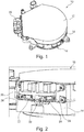
- FIG. figure 1 An example of a voltage converter according to the invention is shown in FIG. figure 1 .
- the voltage converter 10 may have a shape, in particular a substantially cylindrical shape, comprising two bases 12 and an outer lateral wall 14 connecting the two bases 12.
- the voltage converter 10 comprises a terminal block 20.
- the terminal block 20 can be fixed to the voltage converter 10 by screwing, as shown in FIG. figure 2 .
- the terminal block 20 can be fixed on the outer side wall 14 of the voltage converter 10.
- the figure 2 represents an enlarged view of the terminal block of the voltage converter according to the invention.
- the terminal block 20 is intended to electrically connect the voltage converter 10 and an electrical network, for example an electrical network of a motor vehicle.
- the terminal 20 comprises a first filtering component 22 and a second filtering component 24.
- the first and second filtering components may comprise one or more capacitors.
- the terminal block 20 also comprises a first power trace 26, a second power trace 28 and a third power trace 30.
- a trace of power is an electrically conductive trace, especially metal, for example copper.
- a power trace may be a metal blade or a metal bar.
- a power trace is intended to transmit an electric current between the electrical network and the electrical machine.
- the first power trace 26 is intended to electrically connect a first pole of the electrical network to the voltage converter.
- the first pole of the power grid is a positive polarity pole + 48V.
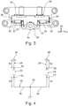
- the first power trace 26 comprises a first connection terminal 32, in particular represented on the figure 3 , electrically connected to the first filtering component 22 and a second connection terminal 34, also visible on the figure 3 , intended to be electrically connected to the first pole of the electrical network.
- the second power trace 28 is intended to electrically connect a second pole of the electrical network to the voltage converter.
- the second pole of the electrical network is a polarity pole equal to 0V.
- the second power trace 28 comprises a first connection terminal 36 electrically connected to the second filtering component 24 and a second connection terminal 38 intended to be electrically connected to the second pole of the electrical network, the first and second connection terminals 36, 38 being represented on the figure 3 .
- the third power trace 30 is for electrically connecting a reference potential pole to the first and second filtering components 22, 24.
- the reference potential pole is a polarity pole equal to 12V, or the pole of reference potential is a pole having a potential of electrical mass.
- the reference potential pole is formed by a chassis on which the voltage converter 10 is mounted.
- the third power trace 30 may be electrically connected to the reference potential pole via the side wall 14.
- the third power trace 30 comprises a first connection terminal 40 electrically connected to the first filtering component 22, a second connection terminal 42 electrically connected to the second filtering component 24, and a third connection terminal 44 intended to be electrically connected to the reference potential pole.
- the third connection terminal 44 of the third power trace 30 is connected to the voltage converter and in particular to a support of the voltage converter having the reference potential.
- the first, second and third power traces 26, 28, 30 are distinct from each other and may be partially overmolded electrically insulating material, for example plastic material.
- the figure 4 represents a schematic view of a terminal block, and in particular a common mode filter.
- the common mode filter may comprise two filtering components, here two capacitors.
- the common mode filter may include a plurality of filtering components.
- the first filtering component 22 is electrically connected to the first power trace 26 and to a ground via the third power trace 30.
- the second filtering component 24 is electrically connected to the second power trace 28 and to a ground via the third power trace 30, as shown in FIG. figure 4 .
- D1 denotes the distance between the first and second connection terminals 32, 34 of the first power trace 26 along the first power trace 26.
- the distance D1 corresponds to the length of the first power trace. 26 between the first and second connection terminals 32, 34.
- D3 denotes the distance between the first and third connection terminals 40, 44 of the third power trace 30 along the third power trace 30.
- the distance D3 corresponds to the length of the third trace of power 30 between the first and third terminals 40,44.
- D2 denotes the distance between the first and second connection terminals 36, 38 of the second power trace 28 along the second power trace 28 and D4 the distance between the second and third connection terminals 42, 44 of the third power trace 30 along the third power trace 30.
- the distances D1, D2, D3 and D4 are configured so that the sum of the distances D1 and D3 is greater than or equal to 85% of the sum of the distances D2 and D4 and less than or equal to 115% of the sum of the distances D2 and D4.
- the distances D1, D2, D3 and D4 are configured so as to respect equations (1) and (2). 85 % D 2 + D 4 ⁇ D 1 + D 3 D 1 + D 3 ⁇ 115 % D 2 + D 4
- the distances D1, D2, D3 and D4 can be configured so that the sum of the distances D2 and D4 is greater than or equal to 85% of the sum of the distances D1 and D3 and less than or equal to 115% of the sum of the distances D1 and D3.
- the electromagnetic disturbances that may occur during a current flow in the power traces 26, 28, 30 are limited.
- the difference between the distances D1 and D2 may be less than or equal to 10% of the maximum distance between the distances D1 and D2.
- the absolute value of the difference between the distances D1 and D2 is less than or equal to 10% of the maximum distance among the distances D1 and D2.
- the difference between the distances D1 and D2 is the smallest distance possible. In other words, the difference between the distances D1 and D2 tends to be zero. According to a preferred embodiment, the distances D1 and D2 are equal.
- the difference between the distances D3 and D4 may be less than or equal to 10% of the maximum distance between the distances D3 and D4. According to a preferred embodiment, the distances D3 and D4 are equal. In other words, the difference between the distances D3 and D4 is zero.
- a symmetry between the distances D1 and D3 and between the distances D2 and D4, as well as between the sum of the distances D1 and D2 and the sum of the distances D3 and D4, makes it possible to reduce the electromagnetic disturbances emitted within the voltage converter, and therefore improve the electromagnetic compatibility between the voltage converter and the power grid.
- the sum of the distances D1 and D3 may be less than or equal to 100 mm, and preferably less than or equal to 60 mm.
- the distances D1 and D3 are as short as possible, for example the sum of the distances D1 and D3 may be less than or equal to 20 mm.
- the distances D1 and D3 are each less than or equal to 10 mm
- the sum of the distances D2 and D4 may be less than or equal to 100 mm, preferably less than or equal to 60 mm, and more preferably less than or equal to 20 mm
- the distances D1, D2, D3 and D4 respect the equations (3) and (4).
- a voltage converter comprising a terminal block in which the distances D1, D2, D3 and D4 comply with the two preceding equations fulfills the criteria of class 4 of the CISPR25 standard.
- a voltage converter comprising a terminal block in which the distances D1, D2, D3 and D4 are configured such that the distances D1 and D3 comply with equation (5) and distances D2 and D4 comply with equation (6), partially meets the criteria of class 4 of CISPR25.
- a voltage converter comprising a terminal block in which the distances D1, D2, D3 and D4 are configured so that the distances D1 and D3 respect the equation (7) and the distances D2 and D4 respect the equation (8). ) does not meet the criteria of Class 4 of CISPR25. 60 mm ⁇ D 1 + D 3 60 mm ⁇ D 2 + D 4
- the third power trace 30 may comprise a first portion 46 and a second portion 48, in particular visible on the figure 4 .
- the first portion 46 of the third power trace 30 may comprise the first and third connection terminals 40, 44 of the third power trace 30.
- the distance D3 may correspond to the length of the first portion 46 of the third trace of power 30.
- the second portion 48 of the third power trace 30 may comprise the second and third connection terminals 42, 44 of the third power trace 30.
- the distance D4 may correspond to the length of the second portion 48 of the third trace of power 30.
- the first power trace 26, the first filtering component 22 and the first portion 46 of the third power trace 30 may be respectively symmetrical to the second power trace 28, to the second filtering component 24 and to the second portion 48 of the third power trace 30 with respect to a plane of symmetry passing through the third connection terminal 44 of the third power trace 30.
- a first portion of the common mode filter comprising the first power trace 26, the first filtering component 22 and the first portion 46 of the third power trace 30 may be symmetrical to a second portion of the common mode filter comprising the second power trace 28, the second filter component 24 and the second portion 48 of the third power trace 30 with respect to a plane orthogonal to an axis noted (y) on the figure 3 .
- connection terminals 34, 38 of the first and second power traces 26, 28 may be arranged symmetrically with respect to the plane passing through the third connection terminal 44 of the third power trace 30.
- connection terminals 34, 38 of the first and second power traces 26, 28 may be arranged symmetrically with respect to a plane extending orthogonally with respect to the axis (y).
- the first connection terminals 32, 36 of the first and second power traces 26, 28 may be arranged symmetrically with respect to the plane passing through the third connection terminal 44 of the third power trace 30.
- the first, second and third power traces 26, 28, 30 may extend longitudinally along the axis (y) and / or along axes noted (x) and (z) on the figure 3 .
- the (x), (y) and (z) axes may be orthogonal to each other.
- the first connection terminals 32, 36 of the first and second power traces 26, 28 may be located respectively on a portion of the first and second power traces 26, 28 extending along the axis (x).
- the first and second connection terminals 40, 42 of the third power trace 30 may be respectively located on a portion of the third power trace 30 extending along the axis (z).
- the second connection terminals 34, 38 of the first and second power traces 26, 28 may be located respectively on a portion of the first and second power traces 26, 28 extending along the axis (y).
- the second connection terminals 34, 38 of the first and second power traces 26, 28 may be adjacent. More specifically, the distance between the second connection terminals 34, 38 of the first and second power traces 26, 28 may be less than 10 mm
- the terminal block according to the invention has been described in the context of a voltage converter on board a motor vehicle and an electrical network of the motor vehicle.
- the invention is not limited to the embodiments described and illustrated, which have been given only as examples. On the contrary, other applications of the terminal block according to the invention are also possible outside the scope of the invention.
Abstract
L'invention concerne un bornier (10), destiné à connecter électriquement un convertisseur de tension, notamment embarqué dans un véhicule automobile, et un réseau électrique, le bornier (10) comprenant : - un premier composant de filtrage (22), - un deuxième composant de filtrage (24), - une première trace de puissance (26), - une deuxième trace de puissance (28), - une troisième trace de puissance (30), dans lequel la distance D1 le long de la première trace de puissance (26), la distance D2 le long de la deuxième trace de puissance (28), les distances D3 et D4 le long de la troisième trace de puissance (30) sont configurées de sorte que la somme des distances D1 et D3 est supérieure ou égale à 85% de la somme des distances D2 et D4 et inférieure ou égale à 115% de la somme des distances D2 et D4.The invention relates to a terminal block (10) for electrically connecting a voltage converter, in particular embedded in a motor vehicle, and an electrical network, the terminal block (10) comprising: a first filtering component (22), a second filtering component (24), a first trace of power (26), a second power trace (28), a third power trace (30), wherein the distance D1 along the first power trace (26), the distance D2 along the second power trace (28), the distances D3 and D4 along the third power trace (30) are configured so that the sum of the distances D1 and D3 is greater than or equal to 85% of the sum of the distances D2 and D4 and less than or equal to 115% of the sum of the distances D2 and D4.
Description
L'invention a pour objet un bornier destiné à connecter électriquement un convertisseur de tension, notamment embarqué dans un véhicule automobile, et un réseau électrique.The invention relates to a terminal block for electrically connecting a voltage converter, in particular embedded in a motor vehicle, and an electrical network.
L'invention concerne également un convertisseur de tension comprenant un tel bornier et un équipement électrique comprenant une machine électrique et un tel convertisseur de tension.The invention also relates to a voltage converter comprising such a terminal block and an electrical equipment comprising an electric machine and such a voltage converter.
En général, un moteur électrique, notamment pour véhicule automobile, comprend un convertisseur de tension, supporté par un châssis, comprenant des unités électroniques de puissance contrôlées par une unité électronique de contrôle.In general, an electric motor, particularly for a motor vehicle, comprises a voltage converter, supported by a chassis, comprising electronic power units controlled by an electronic control unit.
Le convertisseur de tension peut également comprendre un bloc de condensateurs configuré pour stabiliser une tension électrique reçue par les unités électroniques de puissance et pour réduire les perturbations électromagnétiques générées par les unités électroniques de puissance et de contrôle.The voltage converter may also include a capacitor block configured to stabilize an electrical voltage received by the electronic power units and to reduce the electromagnetic disturbances generated by the electronic power and control units.
En particulier, les unités électroniques de puissance sont alimentées par une interface de puissance, par exemple comprise dans un bornier. Cependant, dans un tel moteur électrique, la masse de l'interface de puissance du bornier est reliée par un câble électrique au convertisseur de tension, ce qui a pour conséquence une génération de perturbations électromagnétiques au sein dudit convertisseur de tension, et notamment au niveau des unités électroniques de puissance et de contrôle.In particular, the electronic power units are powered by a power interface, for example included in a terminal block. However, in such an electric motor, the ground of the power interface of the terminal block is connected by an electric cable to the voltage converter, which results in a generation of electromagnetic disturbances within said voltage converter, and in particular at the electronic power and control units.
Afin de réduire, voire supprimer, ces perturbations électromagnétiques, un filtre de mode commun est généralement intégré au niveau de l'unité électronique de contrôle.In order to reduce or even eliminate these electromagnetic disturbances, a common mode filter is generally integrated at the level of the electronic control unit.
Pour réaliser ce filtre de mode commun, l'unité électronique de contrôle est connectée électriquement au châssis, afin de faire un filtre de mode commun entre le châssis et l'interface de puissance.To achieve this common mode filter, the electronic control unit is electrically connected to the chassis, to make a common mode filter between the chassis and the power interface.
Il est connu l'intégration d'un filtre de mode commun externe à un convertisseur de tension. Un tel filtre de mode commun comprend deux condensateurs reliés par des traces de puissance surmoulées de résine et connectées à des bornes de l'interface de puissance du bornier et au châssis. Le filtre de mode commun comprend également une protection configurée pour protéger la résine de la chaleur émise par les unités électroniques de puissance et de contrôle au sein du convertisseur de tension.It is known to integrate an external common mode filter with a voltage converter. Such a common mode filter comprises two capacitors connected by over-molded resin power traces and connected to terminals of the terminal block power interface and the chassis. The common mode filter also includes a protection configured to protect the resin from the heat emitted by the electronic power and control units within the voltage converter.
Cependant, cette solution technique est coûteuse car elle utilise des pièces spécifiques, notamment une protection et des traces de puissance suffisamment longues pour connecter électriquement l'interface de puissance du bornier au châssis.However, this technical solution is expensive because it uses specific parts, including protection and traces of power long enough to electrically connect the power interface of the terminal block to the chassis.
De plus, cette solution technique est encombrante, et de ce fait, le filtre de mode commun est difficile à intégrer au convertisseur de tension.In addition, this technical solution is cumbersome, and because of this, the common mode filter is difficult to integrate with the voltage converter.
En outre, de telles traces de puissance ne permettent pas de supprimer la génération de perturbations électromagnétiques au sein du convertisseur de tension.In addition, such power traces do not make it possible to suppress the generation of electromagnetic disturbances within the voltage converter.
Il est également connu l'intégration d'un filtre de mode commun directement dans un bloc de condensateurs d'un convertisseur de tension. Un tel filtre de mode commun comprend deux condensateurs du bloc de condensateurs reliés par des traces de puissance connectées à des bornes de l'interface de puissance du bornier et au châssis.It is also known to integrate a common mode filter directly into a capacitor block of a voltage converter. Such a common mode filter comprises two capacitors of the capacitor block connected by power traces connected to terminals of the power interface of the terminal block and to the chassis.
Néanmoins, le bloc de condensateurs étant volumineux, le filtre de mode commun est difficile à intégrer au convertisseur de tension.Nevertheless, since the capacitor block is bulky, the common mode filter is difficult to integrate with the voltage converter.
De plus, cette solution technique nécessite des traces de puissance suffisamment longues pour connecter électriquement l'interface de puissance du bornier au châssis.In addition, this technical solution requires sufficiently long power traces to electrically connect the power interface of the terminal block to the chassis.
En outre, la connexion électrique entre le bloc de condensateurs et le châssis est difficile à réaliser.In addition, the electrical connection between the capacitor block and the chassis is difficult to achieve.
La présente invention vise à remédier à ces inconvénients en proposant un bornier intégrant un filtre de mode commun. Un tel bornier permet une optimisation de l'intégration du filtre de mode commun au niveau du convertisseur de tension et une optimisation de la compatibilité électromagnétique des unités électroniques au sein du convertisseur de tension.The present invention aims to overcome these disadvantages by providing a terminal block incorporating a common mode filter. Such a terminal block allows an optimization of the integration of the common mode filter at the level of the voltage converter and an optimization of the electromagnetic compatibility of the electronic units within the voltage converter.
A cet effet, l'invention a pour objet un bornier destiné à connecter électriquement un convertisseur de tension, notamment embarqué dans un véhicule automobile, et un réseau électrique, le bornier comprenant :
- un premier composant de filtrage,
- un deuxième composant de filtrage,
- une première trace de puissance, destinée à relier électriquement un premier pôle du réseau électrique au convertisseur de tension, la première trace de puissance comprenant une première borne de connexion connectée électriquement au premier composant de filtrage et une deuxième borne de connexion destinée à être connectée électriquement au premier pôle du réseau électrique,
- une deuxième trace de puissance, destinée à relier électriquement un deuxième pôle du réseau électrique au convertisseur de tension, la deuxième trace de puissance comprenant une première borne de connexion connectée électriquement au deuxième composant de filtrage et une deuxième borne de connexion destinée à être connectée électriquement au deuxième pôle du réseau électrique,
- une troisième trace de puissance, destinée à connecter électriquement un pôle de potentiel de référence aux premier et deuxième composants de filtrage, la troisième trace de puissance comprenant une première borne de connexion connectée électriquement au premier composant de filtrage, une deuxième borne de connexion connectée électriquement au deuxième composant de filtrage, et une troisième borne de connexion destinée à être connectée électriquement au pôle de potentiel de référence,
- a first filtering component,
- a second filtering component,
- a first power trace, for electrically connecting a first pole of the power network to the voltage converter, the first power trace comprising a first connection terminal electrically connected to the first filtering component and a second connection terminal intended to be electrically connected at the first pole of the electricity network,
- a second power trace, for electrically connecting a second pole of the electrical network to the voltage converter, the second power trace comprising a first connection terminal electrically connected to the second filtering component and a second connection terminal intended to be electrically connected at the second pole of the electricity network,
- a third power trace, for electrically connecting a reference potential pole to the first and second filtering components, the third power trace comprising a first connection terminal electrically connected to the first filtering component, a second electrically connected connecting terminal; to the second filter component, and a third connection terminal to be electrically connected to the reference potential pole,
Notamment, les distances D1, D2, D3, D4 sont telles que D1+D3 = D2+D4.In particular, the distances D1, D2, D3, D4 are such that D1 + D3 = D2 + D4.
Avantageusement, le bornier selon l'invention permet d'optimiser la compatibilité électromagnétique entre le convertisseur de tension et le réseau électrique. Plus précisément, la relation entre les distances D1, D2, D3, D4 permet de limiter, voire même de rendre négligeables, les perturbations électromagnétiques émises dans le convertisseur de tension.Advantageously, the terminal block according to the invention makes it possible to optimize the electromagnetic compatibility between the voltage converter and the electrical network. More precisely, the relationship between the distances D1, D2, D3, D4 makes it possible to limit, or even to render negligible, the electromagnetic disturbances emitted in the voltage converter.
Le bornier selon l'invention peut également comprendre une ou plusieurs des caractéristiques suivantes, considérées individuellement ou selon toutes les combinaisons possibles :
- la différence entre les distances D1 et D2 est inférieure ou égale 10% de la distance maximale entre les distances D1 et D2, et la différence entre les distances D3 et D4 est inférieure ou égale 10% de la distance maximale entre les distances D3 et D4 ; notamment les distances D1 et D2 sont égales, et les distances D3 et D4 sont égales et/ou
- la somme des distances D1 et D3, et la somme des distances D2 et D4, sont inférieures ou égale à 100 mm, de préférence inférieure ou égale à 60 mm, et plus préférentiellement inférieure ou égale à 20 mm ; et/ou
- les premier et deuxième composants de filtrage comprennent respectivement au moins un condensateur ; et/ou
- la troisième trace de puissance comprend une première portion, comprenant les première et troisième bornes de connexion de la troisième trace de puissance, et une deuxième portion, comprenant les deuxième et troisième bornes de connexion de la troisième trace de puissance, et dans lequel la première trace de puissance, le premier composant de filtrage et la première portion de la troisième trace de puissance sont respectivement symétriques à la deuxième trace de puissance, au deuxième composant de filtrage et à la deuxième portion de la troisième trace de puissance par rapport à un plan de symétrie passant par la troisième borne de connexion de la troisième trace de puissance ; et/ou
- les deuxièmes bornes de connexion des première et deuxième traces de puissance sont disposées symétriquement par rapport au plan passant par la troisième borne de connexion de la troisième trace de puissance ; et/ou
- les premières bornes de connexion des première et deuxième traces de puissance sont disposées symétriquement par rapport au plan passant par la troisième borne de connexion de la troisième trace de puissance ; et/ou
- les première, deuxième et troisième traces de puissance s'étendent longitudinalement selon un premier axe (x), un deuxième axe (y) et un troisième axe (z), les axes (x, y, z) étant orthogonaux entre eux ; et/ou
- les premières bornes de connexion des première et deuxième traces de puissance sont respectivement situées sur une portion des première et deuxième traces de puissance s'étendant selon le premier axe (x) ; et/ou
- les deuxièmes bornes de connexion des première et deuxième traces de puissance sont respectivement situées sur une portion des première et deuxième traces de puissance s'étendant selon le deuxième axe (y) ; et/ou
- les première et deuxième bornes de connexion de la troisième trace de puissance sont respectivement situées sur une portion de la troisième trace de puissance s'étendant selon le troisième axe (z) ; et/ou
- les deuxièmes bornes de connexion des première et deuxième traces de puissance sont adjacentes ; et/ou
- les première, deuxième et troisième traces de puissance sont en partie surmoulées de matériau isolant électriquement ; et/ou
- le matériau isolant électriquement est un matériau plastique ; et/ou
- les première, deuxième et troisième traces de puissance sont des lames métalliques ; et/ou
- les première, deuxième et troisième traces de puissance sont des barreaux métalliques.
- the difference between the distances D1 and D2 is less than or equal to 10% of the maximum distance between the distances D1 and D2, and the difference between the distances D3 and D4 is less than or equal to 10% of the maximum distance between the distances D3 and D4 ; in particular the distances D1 and D2 are equal, and the distances D3 and D4 are equal and / or
- the sum of the distances D1 and D3, and the sum of the distances D2 and D4, are less than or equal to 100 mm, preferably less than or equal to 60 mm, and more preferably less than or equal to 20 mm; and or
- the first and second filtering components respectively comprise at least one capacitor; and or
- the third power trace comprises a first portion, comprising the first and third connection terminals of the third power trace, and a second portion, comprising the second and third connection terminals of the third power trace, and wherein the first trace of power, the first filtering component and the first portion of the third power trace are respectively symmetrical to the second power trace, the second filter component and the second portion of the third power trace with respect to a plane of symmetry passing through the third connection terminal of the third trace of power; and or
- the second connection terminals of the first and second power traces are arranged symmetrically with respect to the plane passing through the third connection terminal of the third power trace; and or
- the first connection terminals of the first and second power traces are arranged symmetrically with respect to the plane passing through the third connection terminal of the third power trace; and or
- the first, second and third power traces extend longitudinally along a first axis (x), a second axis (y) and a third axis (z), the axes (x, y, z) being orthogonal to each other; and or
- the first connection terminals of the first and second power traces are respectively located on a portion of the first and second power traces extending along the first axis (x); and or
- the second connection terminals of the first and second power traces are respectively located on a portion of the first and second power traces extending along the second axis (y); and or
- the first and second terminals of the third power trace are respectively located on a portion of the third power trace extending along the third axis (z); and or
- the second connection terminals of the first and second power traces are adjacent; and or
- the first, second and third power traces are partially overmolded with electrically insulating material; and or
- the electrically insulating material is a plastic material; and or
- the first, second and third power traces are metal blades; and or
- the first, second and third power traces are metal bars.
L'invention se rapporte également à un convertisseur de tension destiné à contrôler une énergie électrique échangée entre une machine électrique et une source d'alimentation électrique, notamment d'un réseau électrique d'un véhicule automobile, ledit convertisseur de tension comprenant un bornier selon l'invention, et dans lequel la troisième borne de connexion de la troisième trace de puissance est connectée à un support du convertisseur de tension, ledit support formant le pôle de potentiel de référence.The invention also relates to a voltage converter for controlling an electrical energy exchanged between an electrical machine and a power supply source, in particular an electrical network of a motor vehicle, said voltage converter comprising a terminal block according to the invention, and wherein the third connection terminal of the third power trace is connected to a support of the voltage converter, said support forming the reference potential pole.
Avantageusement, l'intégration d'un filtre de mode commun au niveau du bornier dudit convertisseur de tension permet de réduire les coûts de production dudit convertisseur de tension.Advantageously, the integration of a common mode filter at the terminal block of said voltage converter makes it possible to reduce the production costs of said voltage converter.
En outre, un tel convertisseur de tension a une compatibilité électromagnétique améliorée par rapport aux convertisseurs de tension de l'art antérieur.In addition, such a voltage converter has improved electromagnetic compatibility over voltage converters of the prior art.
Le convertisseur de tension selon l'invention peut également comprendre une ou plusieurs des caractéristiques suivantes, considérées individuellement ou selon toutes les combinaisons possibles :
- le bornier est fixé au convertisseur de tension par vissage ; et/ou
- le convertisseur de tension a une forme sensiblement cylindrique, le bornier étant fixé sur une paroi latérale extérieure de la forme sensiblement cylindrique du convertisseur de tension.
- the terminal block is fixed to the voltage converter by screwing; and or
- the voltage converter has a substantially cylindrical shape, the terminal block being fixed on an outer side wall of the substantially cylindrical shape of the voltage converter.
L'invention concerne également un équipement électrique comprenant une machine électrique et un convertisseur de tension selon l'invention destiné à contrôler une énergie électrique échangée entre la machine électrique et une source d'alimentation électrique, et dans lequel le convertisseur de tension est monté sur la machine électrique.The invention also relates to an electrical equipment comprising an electrical machine and a voltage converter according to the invention for controlling an electrical energy exchanged between the electrical machine and a power supply source, and in which the voltage converter is mounted on the electric machine.
D'autres caractéristiques et avantages de la présente invention apparaitront à la lecture de la description détaillée de modes de réalisation donnés à titre d'exemples non limitatifs et illustrés, accompagnée des figures suivantes :
- la
figure 1 représente un convertisseur de tension selon un mode de réalisation de l'invention, - la
figure 2 représente une vue agrandie d'un convertisseur de tension selon un mode de réalisation de l'invention, - la
figure 3 est une vue en coupe d'un bornier selon l'invention, et - la
figure 4 est une vue schématique d'un bornier selon un mode de réalisation de l'invention.
- the
figure 1 represents a voltage converter according to one embodiment of the invention, - the
figure 2 represents an enlarged view of a voltage converter according to one embodiment of the invention, - the
figure 3 is a sectional view of a terminal block according to the invention, and - the
figure 4 is a schematic view of a terminal block according to one embodiment of the invention.
Il est à noter que ces dessins n'ont d'autre but que d'illustrer le texte de la description et ne constituent en aucune sorte une limitation de la portée de l'invention.It should be noted that these drawings have no other purpose than to illustrate the text of the description and do not constitute in any way a limitation of the scope of the invention.
Sur les différentes figures, les éléments analogues sont désignés par des références identiques.In the various figures, the analogous elements are designated by identical references.
L'invention concerne un équipement électrique, notamment pour véhicule automobile, comprenant une machine électrique et un convertisseur de tension.The invention relates to an electrical equipment, particularly for a motor vehicle, comprising an electric machine and a voltage converter.
Le convertisseur de tension est destiné à contrôler une énergie électrique échangée entre la machine électrique et une source d'alimentation électrique. Le convertisseur de tension peut être embarqué dans un véhicule automobile. Le convertisseur de tension peut être par exemple un onduleur de tension. En particulier, le convertisseur de tension est monté sur la machine électrique.The voltage converter is for controlling electrical energy exchanged between the electrical machine and a power source. The voltage converter can be embedded in a motor vehicle. The voltage converter can be for example a voltage inverter. In particular, the voltage converter is mounted on the electric machine.
La source d'alimentation électrique peut être un réseau électrique, notamment un réseau électrique d'un véhicule automobile. Un réseau électrique est par exemple un réseau électrique alimenté par une tension électrique de +48V. De préférence, le réseau électrique est un réseau d'énergie électrique continue. Le réseau électrique peut comprendre une batterie alimentant ledit réseau électrique.The power source can be an electrical network, including an electrical network of a motor vehicle. An electrical network is for example an electrical network powered by an electrical voltage of + 48V. Preferably, the electrical network is a network of continuous electrical energy. The electrical network may include a battery supplying said electrical network.
Un exemple d'un convertisseur de tension selon l'invention est représenté en
Le convertisseur de tension 10 peut avoir une forme, notamment sensiblement cylindrique, comprenant deux bases 12 et une paroi latérale extérieure 14 reliant les deux bases 12.The
Le convertisseur de tension 10 comprend un bornier 20. En particulier, le bornier 20 peut être fixé au convertisseur de tension 10 par vissage, comme représenté sur la
La
Le bornier 20 est destiné à connecter électriquement le convertisseur de tension 10 et un réseau électrique, par exemple un réseau électrique d'un véhicule automobile.The
Le bornier 20 comprend un premier composant de filtrage 22 et un deuxième composant de filtrage 24. Les premier et deuxième composants de filtrage peuvent comprendre un ou plusieurs condensateurs.The terminal 20 comprises a
Le bornier 20 comprend également une première trace de puissance 26, une deuxième trace de puissance 28 et une troisième trace de puissance 30.The
Une trace de puissance est une trace conductrice électriquement, notamment métallique, par exemple en cuivre. Une trace de puissance peut être une lame métallique ou un barreau métallique. Une trace de puissance est destinée à transmettre un courant électrique entre le réseau électrique et la machine électrique.A trace of power is an electrically conductive trace, especially metal, for example copper. A power trace may be a metal blade or a metal bar. A power trace is intended to transmit an electric current between the electrical network and the electrical machine.
La première trace de puissance 26 est destinée à relier électriquement un premier pôle du réseau électrique au convertisseur de tension. Par exemple, le premier pôle du réseau électrique est un pôle de polarité positive +48V.The
La première trace de puissance 26 comprend une première borne de connexion 32, notamment représentée sur la
La deuxième trace de puissance 28 est destinée à relier électriquement un deuxième pôle du réseau électrique au convertisseur de tension. Par exemple, le deuxième pôle du réseau électrique est un pôle de polarité égale à 0V.The
La deuxième trace de puissance 28 comprend une première borne de connexion 36 connectée électriquement au deuxième composant de filtrage 24 et une deuxième borne de connexion 38 destinée à être connectée électriquement au deuxième pôle du réseau électrique, les première et deuxièmes bornes de connexion 36, 38 étant représentées sur la
La troisième trace de puissance 30 est destinée à connecter électriquement un pôle de potentiel de référence aux premier et deuxième composants de filtrage 22, 24. Par exemple, le pôle de potentiel de référence est un pôle de polarité égale à 12V, ou le pôle de potentiel de référence est un pôle ayant un potentiel de masse électrique. En particulier, le pôle de potentiel de référence est formé par un châssis sur lequel le convertisseur de tension 10 est monté. Par exemple, la troisième trace de puissance 30 peut être reliée électriquement au pôle de potentiel de référence par l'intermédiaire de la paroi latérale 14.The
Comme illustré sur la
Comme représenté sur la
Les première, deuxième et troisième traces de puissance 26, 28, 30 sont distinctes l'une de l'autre et peuvent être en partie surmoulées de matériau isolant électriquement, par exemple de matériau plastique.The first, second and third power traces 26, 28, 30 are distinct from each other and may be partially overmolded electrically insulating material, for example plastic material.
La
Le filtre de mode commun peut comprendre deux composants de filtrage, ici deux condensateurs. Bien entendu, le filtre de mode commun peut comprendre une pluralité de composants de filtrage.The common mode filter may comprise two filtering components, here two capacitors. Of course, the common mode filter may include a plurality of filtering components.
Sur la
Le deuxième composant de filtrage 24 est connecté électriquement à la deuxième trace de puissance 28 et à une masse via la troisième trace de puissance 30, comme représenté sur la
Comme représenté sur la
De plus, on note D3 la distance entre les première et troisième bornes de connexion 40, 44 de la troisième trace de puissance 30 le long de la troisième trace de puissance 30. Autrement dit, la distance D3 correspond à la longueur de la troisième trace de puissance 30 entre les première et troisième bornes de connexion 40,44.In addition, D3 denotes the distance between the first and
De façon analogue, comme illustré sur la
Les distances D1, D2, D3 et D4 sont configurées de sorte que la somme des distances D1 et D3 est supérieure ou égale à 85% de la somme des distances D2 et D4 et inférieure ou égale à 115% de la somme des distances D2 et D4.The distances D1, D2, D3 and D4 are configured so that the sum of the distances D1 and D3 is greater than or equal to 85% of the sum of the distances D2 and D4 and less than or equal to 115% of the sum of the distances D2 and D4.
Autrement dit, les distances D1, D2, D3 et D4 sont configurées de sorte à respecter les équations (1) et (2). ![]()
![]()
![]()
![]()
De façon similaire, les distances D1, D2, D3 et D4 peuvent être configurées de sorte que la somme des distances D2 et D4 est supérieure ou égale à 85% de la somme des distances D1 et D3 et inférieure ou égale à 115% de la somme des distances D1 et D3.Similarly, the distances D1, D2, D3 and D4 can be configured so that the sum of the distances D2 and D4 is greater than or equal to 85% of the sum of the distances D1 and D3 and less than or equal to 115% of the sum of the distances D1 and D3.
En limitant la différence entre la somme D1+D3 des distances D1, D3 et la somme D2+D4 des distances D2, D4, les perturbations électromagnétiques susceptibles d'apparaitre lors d'une circulation de courant dans les traces de puissance 26, 28, 30 sont limitées.By limiting the difference between the sum D1 + D3 of the distances D1, D3 and the sum D2 + D4 of the distances D2, D4, the electromagnetic disturbances that may occur during a current flow in the power traces 26, 28, 30 are limited.
En particulier, les distances D1, D2, D3 et D4 peuvent être telles que D1+D3 = D2+D4, ce qui permet de rendre négligeable ces perturbations électromagnétiques.In particular, the distances D1, D2, D3 and D4 can be such that D1 + D3 = D2 + D4, which makes negligible these electromagnetic disturbances.
La différence entre les distances D1 et D2 peut être inférieure ou égale 10% de la distance maximale entre les distances D1 et D2. Autrement dit, la valeur absolue de la différence entre les distances D1 et D2 est inférieure ou égale à 10% de la distance maximale parmi les distances D1 et D2.The difference between the distances D1 and D2 may be less than or equal to 10% of the maximum distance between the distances D1 and D2. In other words, the absolute value of the difference between the distances D1 and D2 is less than or equal to 10% of the maximum distance among the distances D1 and D2.
De préférence, la différence entre les distances D1 et D2 est la distance la plus petite possible. Autrement dit, la différence entre les distances D1 et D2 tend à être nulle. Selon un mode de réalisation préféré, les distances D1 et D2 sont égales.Preferably, the difference between the distances D1 and D2 is the smallest distance possible. In other words, the difference between the distances D1 and D2 tends to be zero. According to a preferred embodiment, the distances D1 and D2 are equal.
De façon similaire, la différence entre les distances D3 et D4 peut être inférieure ou égale 10% de la distance maximale entre les distances D3 et D4. Selon un mode de réalisation préféré, les distances D3 et D4 sont égales. Autrement dit, la différence entre les distances D3 et D4 est nulle.Similarly, the difference between the distances D3 and D4 may be less than or equal to 10% of the maximum distance between the distances D3 and D4. According to a preferred embodiment, the distances D3 and D4 are equal. In other words, the difference between the distances D3 and D4 is zero.
Grâce à ces relations entre les distances D1, D2 d'une part et les distances D3, D4 d'autre part, les perturbations électromagnétiques sont encore plus diminuées.Thanks to these relations between the distances D1, D2 on the one hand and the distances D3, D4 on the other hand, the electromagnetic disturbances are even more diminished.
Une symétrie entre les distances D1 et D3 et entre les distances D2 et D4, ainsi qu'entre la somme des distances D1 et D2 et la somme des distances D3 et D4, permet de réduire les perturbations électromagnétiques émises au sein du convertisseur de tension, et par conséquent d'améliorer la compatibilité électromagnétique entre le convertisseur de tension et le réseau électrique.A symmetry between the distances D1 and D3 and between the distances D2 and D4, as well as between the sum of the distances D1 and D2 and the sum of the distances D3 and D4, makes it possible to reduce the electromagnetic disturbances emitted within the voltage converter, and therefore improve the electromagnetic compatibility between the voltage converter and the power grid.
La somme des distances D1 et D3 peut être inférieure ou égale à 100 mm, et de préférence inférieure ou égale à 60 mm. Préférentiellement, les distances D1 et D3 sont les plus courtes possibles, par exemple la somme des distances D1 et D3 peut être inférieure ou égale à 20 mm. Selon un mode de réalisation préféré, les distances D1 et D3 sont chacune inférieure ou égale à 10 mmThe sum of the distances D1 and D3 may be less than or equal to 100 mm, and preferably less than or equal to 60 mm. Preferably, the distances D1 and D3 are as short as possible, for example the sum of the distances D1 and D3 may be less than or equal to 20 mm. According to a preferred embodiment, the distances D1 and D3 are each less than or equal to 10 mm
De la même manière, la somme des distances D2 et D4 peut être inférieure ou égale à 100 mm, de préférence inférieure ou égale à 60 mm, et plus préférentiellement inférieure ou égale à 20 mmIn the same manner, the sum of the distances D2 and D4 may be less than or equal to 100 mm, preferably less than or equal to 60 mm, and more preferably less than or equal to 20 mm
Selon un mode de réalisation préféré, les distances D1, D2, D3 et D4 respectent les équations (3) et (4). ![]()
![]()
![]()
![]()
Avantageusement, un convertisseur de tension comprenant un bornier dans lequel les distances D1, D2, D3 et D4 respectent les deux équations précédentes remplit les critères de la classe 4 de la norme CISPR25.Advantageously, a voltage converter comprising a terminal block in which the distances D1, D2, D3 and D4 comply with the two preceding equations fulfills the criteria of class 4 of the CISPR25 standard.
De plus, un convertisseur de tension comprenant un bornier dans lequel les distances D1, D2, D3 et D4 sont configurées telles que les distances D1 et D3 respectent l'équation (5) et les distances D2 et D4 respectent l'équation (6), remplit partiellement les critères de la classe 4 de la norme CISPR25. ![]()
![]()
![]()
![]()
En outre, un convertisseur de tension comprenant un bornier dans lequel les distances D1, D2, D3 et D4 sont configurées de sorte que les distances D1 et D3 respectent l'équation (7) et les distances D2 et D4 respectent l'équation (8) ne remplit pas les critères de la classe 4 de la norme CISPR25. ![]()
![]()
![]()
![]()
En outre, la troisième trace de puissance 30 peut comprendre une première portion 46 et une deuxième portion 48, notamment visibles sur la
La première portion 46 de la troisième trace de puissance 30 peut comprendre les première et troisième bornes de connexion 40, 44 de la troisième trace de puissance 30. Par exemple, la distance D3 peut correspondre à la longueur de la première portion 46 de la troisième trace de puissance 30.The
La deuxième portion 48 de la troisième trace de puissance 30 peut comprendre les deuxième et troisième bornes de connexion 42, 44 de la troisième trace de puissance 30. Par exemple, la distance D4 peut correspondre à la longueur de la deuxième portion 48 de la troisième trace de puissance 30.The
Comme représenté sur la
Autrement dit, une première portion du filtre de mode commun comprenant la première trace de puissance 26, le premier composant de filtrage 22 et la première portion 46 de la troisième trace de puissance 30 peut être symétrique à une deuxième portion du filtre de mode commun comprenant la deuxième trace de puissance 28, au deuxième composant de filtrage 24 et à la deuxième portion 48 de la troisième trace de puissance 30 par rapport à un plan orthogonal à un axe noté (y) sur la
En particulier, les deuxièmes bornes de connexion 34, 38 des première et deuxième traces de puissance 26, 28 peuvent être disposées symétriquement par rapport au plan passant par la troisième borne de connexion 44 de la troisième trace de puissance 30.In particular, the
Autrement dit, les deuxièmes bornes de connexion 34, 38 des première et deuxième traces de puissance 26, 28 peuvent être disposées symétriquement par rapport à un plan s'étendant orthogonalement par rapport à l'axe (y).In other words, the
Les premières bornes de connexion 32, 36 des première et deuxième traces de puissance 26, 28 peuvent être disposées symétriquement par rapport au plan passant par la troisième borne de connexion 44 de la troisième trace de puissance 30.The
Les première, deuxième et troisième traces de puissance 26, 28, 30 peuvent s'étendre longitudinalement selon l'axe (y) et/ou selon des axes notés (x) et (z) sur la
Les premières bornes de connexion 32, 36 des première et deuxième traces de puissance 26, 28 peuvent être respectivement situées sur une portion des première et deuxième traces de puissance 26, 28 s'étendant selon l'axe (x).The
Les première et deuxième bornes de connexion 40, 42 de la troisième trace de puissance 30 peuvent être respectivement situées sur une portion de la troisième trace de puissance 30 s'étendant selon l'axe (z).The first and
Les deuxièmes bornes de connexion 34, 38 des première et deuxième traces de puissance 26, 28 peuvent être respectivement situées sur une portion des première et deuxième traces de puissance 26, 28 s'étendant selon l'axe (y).The
Les deuxièmes bornes de connexion 34, 38 des première et deuxième traces de puissance 26, 28 peuvent être adjacentes. Plus précisément, la distance entre les deuxièmes bornes de connexion 34, 38 des première et deuxième traces de puissance 26, 28 peut être inférieure à 10 mmThe
Le bornier selon l'invention a été décrit dans le cadre d'un convertisseur de tension embarqué dans un véhicule automobile et d'un réseau électrique du véhicule automobile. Bien entendu, l'invention n'est nullement limitée aux modes de réalisation décrits et illustrés, qui n'ont été donnés qu'à titre d'exemples. Au contraire, d'autres applications du bornier conforme à l'invention sont également possibles dans sortir du cadre de l'invention.The terminal block according to the invention has been described in the context of a voltage converter on board a motor vehicle and an electrical network of the motor vehicle. Of course, the invention is not limited to the embodiments described and illustrated, which have been given only as examples. On the contrary, other applications of the terminal block according to the invention are also possible outside the scope of the invention.
Claims (7)
Applications Claiming Priority (1)
| Application Number | Priority Date | Filing Date | Title |
|---|---|---|---|
| FR1657151A FR3054498B1 (en) | 2016-07-26 | 2016-07-26 | TERMINAL FOR A MOTOR VEHICLE, VOLTAGE CONVERTER COMPRISING SAME, AND ELECTRICAL EQUIPMENT COMPRISING SUCH A VOLTAGE CONVERTER |
Publications (2)
| Publication Number | Publication Date |
|---|---|
| EP3275722A1 true EP3275722A1 (en) | 2018-01-31 |
| EP3275722B1 EP3275722B1 (en) | 2021-07-21 |
Family
ID=57190106
Family Applications (1)
| Application Number | Title | Priority Date | Filing Date |
|---|---|---|---|
| EP17182523.5A Active EP3275722B1 (en) | 2016-07-26 | 2017-07-21 | Terminal block for a motor vehicle, voltage converter including same, and electrical equipment including such a voltage converter |
Country Status (3)
| Country | Link |
|---|---|
| EP (1) | EP3275722B1 (en) |
| CN (1) | CN107659165B (en) |
| FR (1) | FR3054498B1 (en) |
Families Citing this family (1)
| Publication number | Priority date | Publication date | Assignee | Title |
|---|---|---|---|---|
| CN112655250B (en) * | 2018-10-31 | 2023-06-27 | Oppo广东移动通信有限公司 | Wireless communication method, terminal equipment and network equipment |
Citations (8)
| Publication number | Priority date | Publication date | Assignee | Title |
|---|---|---|---|---|
| US4359764A (en) * | 1980-04-08 | 1982-11-16 | Block Roger R | Connector for electromagnetic impulse suppression |
| DE3400899A1 (en) * | 1983-01-26 | 1984-08-09 | Feller Ag, Horgen | Device having an interference protection filter for an apparatus which can be connected to AC mains |
| DE29621936U1 (en) * | 1996-12-17 | 1997-09-11 | Shin Jiuh Corp | High voltage suppression filter |
| WO1999017408A1 (en) * | 1997-09-30 | 1999-04-08 | Yun Hyoung Cho | Auxiliary device for removing electronic wave |
| EP1148602A1 (en) * | 2000-04-20 | 2001-10-24 | Mannesmann VDO Aktiengesellschaft | Overvoltage arrester device |
| US20050239305A1 (en) * | 2004-04-22 | 2005-10-27 | Kabushiki Kaisha Audio-Technica | Microphone connector |
| FR2940528A1 (en) * | 2008-12-22 | 2010-06-25 | Valeo Sys Controle Moteur Sas | ELECTRONIC COMPONENT, IN PARTICULAR HALL EFFECT SENSOR |
| DE102010056008A1 (en) * | 2010-12-23 | 2012-06-28 | Volkswagen Ag | Device for electrically contacting electrical component e.g. inverter used in motor car, has electrically-functional element that is connected with electrical component so as to provide electrical contact within housing |
Family Cites Families (7)
| Publication number | Priority date | Publication date | Assignee | Title |
|---|---|---|---|---|
| JP4314513B2 (en) * | 2003-06-18 | 2009-08-19 | アイシン・エィ・ダブリュ株式会社 | Inverter noise remover |
| US7459996B2 (en) * | 2003-12-16 | 2008-12-02 | High & Low Electronics Co., Ltd. | Stable filter and method for forming the same |
| JP4756935B2 (en) * | 2005-06-29 | 2011-08-24 | 本田技研工業株式会社 | Inverter unit with capacitor |
| KR101543039B1 (en) * | 2009-10-26 | 2015-08-10 | 현대자동차주식회사 | Method for constructing capacitor module circuit of inverter using impedance matching |
| ITTO20111086A1 (en) * | 2011-11-25 | 2013-05-26 | Gate Srl | ELECTRICALLY CURRENT MOTOR WITH BRUSHES, PROVIDED WITH A FILTER AGAINST THE EMISSION OF ELECTROMAGNETIC DISORDERS |
| CN204145292U (en) * | 2014-11-06 | 2015-02-04 | 昆明通渡电气有限公司 | A kind of high power switching power supply Electro Magnetic Compatibility filter and filter assembly thereof |
| CN204517653U (en) * | 2014-12-05 | 2015-07-29 | 佛山市顺德区尚研电子科技有限公司 | Difference common mode compound inductance filter band |
-
2016
- 2016-07-26 FR FR1657151A patent/FR3054498B1/en active Active
-
2017
- 2017-07-21 EP EP17182523.5A patent/EP3275722B1/en active Active
- 2017-07-26 CN CN201710616765.1A patent/CN107659165B/en active Active
Patent Citations (8)
| Publication number | Priority date | Publication date | Assignee | Title |
|---|---|---|---|---|
| US4359764A (en) * | 1980-04-08 | 1982-11-16 | Block Roger R | Connector for electromagnetic impulse suppression |
| DE3400899A1 (en) * | 1983-01-26 | 1984-08-09 | Feller Ag, Horgen | Device having an interference protection filter for an apparatus which can be connected to AC mains |
| DE29621936U1 (en) * | 1996-12-17 | 1997-09-11 | Shin Jiuh Corp | High voltage suppression filter |
| WO1999017408A1 (en) * | 1997-09-30 | 1999-04-08 | Yun Hyoung Cho | Auxiliary device for removing electronic wave |
| EP1148602A1 (en) * | 2000-04-20 | 2001-10-24 | Mannesmann VDO Aktiengesellschaft | Overvoltage arrester device |
| US20050239305A1 (en) * | 2004-04-22 | 2005-10-27 | Kabushiki Kaisha Audio-Technica | Microphone connector |
| FR2940528A1 (en) * | 2008-12-22 | 2010-06-25 | Valeo Sys Controle Moteur Sas | ELECTRONIC COMPONENT, IN PARTICULAR HALL EFFECT SENSOR |
| DE102010056008A1 (en) * | 2010-12-23 | 2012-06-28 | Volkswagen Ag | Device for electrically contacting electrical component e.g. inverter used in motor car, has electrically-functional element that is connected with electrical component so as to provide electrical contact within housing |
Also Published As
| Publication number | Publication date |
|---|---|
| CN107659165A (en) | 2018-02-02 |
| CN107659165B (en) | 2022-03-08 |
| EP3275722B1 (en) | 2021-07-21 |
| FR3054498B1 (en) | 2018-07-13 |
| FR3054498A1 (en) | 2018-02-02 |
Similar Documents
| Publication | Publication Date | Title |
|---|---|---|
| EP3501908A1 (en) | Electrical equipment with offset wall | |
| FR2882444A1 (en) | Contact unit for multicontact connector, has body detachably mounted in pocket recess of insulating insert, and opto-electronic converter that converts optical signal or electrical signal into electrical or optical signal | |
| FR2984623A1 (en) | CHARGE CONNECTING / DISCONNECTING DEVICE FOR ENERGY STORAGE UNIT IN A MOTOR VEHICLE | |
| EP3275722B1 (en) | Terminal block for a motor vehicle, voltage converter including same, and electrical equipment including such a voltage converter | |
| EP3668288A1 (en) | Electrical device comprising an insulating film | |
| FR2888661A1 (en) | ELECTRIC CABLE. | |
| FR3076095A1 (en) | HOUSING ELEMENT FOR ELECTRICAL EQUIPMENT | |
| EP2441629A3 (en) | Motor vehicle comprising means to automatically replace a battery and corresponding method of replacing batteries | |
| FR3050878B1 (en) | ELECTRICAL CONNECTION BAR FOR EXCHANGING ELECTRICAL ENERGY BETWEEN AN ELECTRICAL EQUIPMENT AND AN ELECTRICITY NETWORK | |
| WO2016135393A1 (en) | Capacitive box and casing for electric power train | |
| CN105525976A (en) | Cooling fan drive system of vehicle-mounted generator set | |
| FR3083382A1 (en) | ELECTRICAL SYSTEM AND METHOD FOR CHARGING A BATTERY, PARTICULARLY FOR A VEHICLE | |
| EP3727944B1 (en) | Electrically conductive part for an electrical assembly | |
| FR3027854B1 (en) | ELECTRICAL CONNECTION CABLE FOR CHARGING AN ENERGY ACCUMULATOR OF A MOTOR VEHICLE | |
| WO2012072913A1 (en) | Electrical connector socket, and associated connector | |
| FR3056679A1 (en) | DEVICE WITH MASTER AND SLAVE LIGHT MODULES | |
| FR3073096A1 (en) | ELECTRICAL INSULATION BAR, IN PARTICULAR FOR AN ELECTRONIC POWER MODULE OF AN INVERTER | |
| WO2017008859A1 (en) | Electrical heating circuit for a windscreen wiper blade | |
| EP3727943B1 (en) | Electrical connection bar for an electrical assembly | |
| FR3040114A1 (en) | MULTIFUNCTIONAL ELECTRICAL DEVICE | |
| FR3091048A1 (en) | Electrical connection bar | |
| FR3084972A1 (en) | ELECTRICAL ASSEMBLY | |
| WO2016124334A1 (en) | Electronic circuit for controlling a half h bridge | |
| FR3090228B1 (en) | Electric current supply device using a motor vehicle accumulator battery | |
| FR3082693A1 (en) | SUPPLY DEVICE FOR ELECTRIC RADIATOR AND RADIATOR COMPRISING SUCH A DEVICE |
Legal Events
| Date | Code | Title | Description |
|---|---|---|---|
| PUAI | Public reference made under article 153(3) epc to a published international application that has entered the european phase |
Free format text: ORIGINAL CODE: 0009012 |
|
| STAA | Information on the status of an ep patent application or granted ep patent |
Free format text: STATUS: REQUEST FOR EXAMINATION WAS MADE |
|
| STAA | Information on the status of an ep patent application or granted ep patent |
Free format text: STATUS: EXAMINATION IS IN PROGRESS |
|
| 17P | Request for examination filed |
Effective date: 20170721 |
|
| AK | Designated contracting states |
Kind code of ref document: A1 Designated state(s): AL AT BE BG CH CY CZ DE DK EE ES FI FR GB GR HR HU IE IS IT LI LT LU LV MC MK MT NL NO PL PT RO RS SE SI SK SM TR |
|
| AX | Request for extension of the european patent |
Extension state: BA ME |
|
| 17Q | First examination report despatched |
Effective date: 20180119 |
|
| STAA | Information on the status of an ep patent application or granted ep patent |
Free format text: STATUS: EXAMINATION IS IN PROGRESS |
|
| REG | Reference to a national code |
Ref country code: DE Ref legal event code: R079 Ref document number: 602017042381 Country of ref document: DE Free format text: PREVIOUS MAIN CLASS: B60L0011180000 Ipc: H01R0013719000 |
|
| GRAP | Despatch of communication of intention to grant a patent |
Free format text: ORIGINAL CODE: EPIDOSNIGR1 |
|
| STAA | Information on the status of an ep patent application or granted ep patent |
Free format text: STATUS: GRANT OF PATENT IS INTENDED |
|
| RIC1 | Information provided on ipc code assigned before grant |
Ipc: H01R 103/00 20060101ALN20210114BHEP Ipc: H02M 1/42 20070101ALI20210114BHEP Ipc: H02M 1/14 20060101ALI20210114BHEP Ipc: H01R 13/719 20110101AFI20210114BHEP |
|
| RIC1 | Information provided on ipc code assigned before grant |
Ipc: H01R 13/719 20110101AFI20210118BHEP Ipc: H01R 103/00 20060101ALN20210118BHEP Ipc: H02M 1/14 20060101ALI20210118BHEP Ipc: H02M 1/42 20070101ALI20210118BHEP |
|
| INTG | Intention to grant announced |
Effective date: 20210201 |
|
| GRAS | Grant fee paid |
Free format text: ORIGINAL CODE: EPIDOSNIGR3 |
|
| GRAA | (expected) grant |
Free format text: ORIGINAL CODE: 0009210 |
|
| STAA | Information on the status of an ep patent application or granted ep patent |
Free format text: STATUS: THE PATENT HAS BEEN GRANTED |
|
| AK | Designated contracting states |
Kind code of ref document: B1 Designated state(s): AL AT BE BG CH CY CZ DE DK EE ES FI FR GB GR HR HU IE IS IT LI LT LU LV MC MK MT NL NO PL PT RO RS SE SI SK SM TR |
|
| REG | Reference to a national code |
Ref country code: GB Ref legal event code: FG4D Free format text: NOT ENGLISH |
|
| REG | Reference to a national code |
Ref country code: CH Ref legal event code: EP |
|
| REG | Reference to a national code |
Ref country code: DE Ref legal event code: R096 Ref document number: 602017042381 Country of ref document: DE |
|
| REG | Reference to a national code |
Ref country code: AT Ref legal event code: REF Ref document number: 1413476 Country of ref document: AT Kind code of ref document: T Effective date: 20210815 |
|
| REG | Reference to a national code |
Ref country code: IE Ref legal event code: FG4D Free format text: LANGUAGE OF EP DOCUMENT: FRENCH |
|
| REG | Reference to a national code |
Ref country code: LT Ref legal event code: MG9D |
|
| REG | Reference to a national code |
Ref country code: NL Ref legal event code: MP Effective date: 20210721 |
|
| REG | Reference to a national code |
Ref country code: AT Ref legal event code: MK05 Ref document number: 1413476 Country of ref document: AT Kind code of ref document: T Effective date: 20210721 |
|
| PG25 | Lapsed in a contracting state [announced via postgrant information from national office to epo] |
Ref country code: SE Free format text: LAPSE BECAUSE OF FAILURE TO SUBMIT A TRANSLATION OF THE DESCRIPTION OR TO PAY THE FEE WITHIN THE PRESCRIBED TIME-LIMIT Effective date: 20210721 Ref country code: RS Free format text: LAPSE BECAUSE OF FAILURE TO SUBMIT A TRANSLATION OF THE DESCRIPTION OR TO PAY THE FEE WITHIN THE PRESCRIBED TIME-LIMIT Effective date: 20210721 Ref country code: LT Free format text: LAPSE BECAUSE OF FAILURE TO SUBMIT A TRANSLATION OF THE DESCRIPTION OR TO PAY THE FEE WITHIN THE PRESCRIBED TIME-LIMIT Effective date: 20210721 Ref country code: AT Free format text: LAPSE BECAUSE OF FAILURE TO SUBMIT A TRANSLATION OF THE DESCRIPTION OR TO PAY THE FEE WITHIN THE PRESCRIBED TIME-LIMIT Effective date: 20210721 Ref country code: BG Free format text: LAPSE BECAUSE OF FAILURE TO SUBMIT A TRANSLATION OF THE DESCRIPTION OR TO PAY THE FEE WITHIN THE PRESCRIBED TIME-LIMIT Effective date: 20211021 Ref country code: NO Free format text: LAPSE BECAUSE OF FAILURE TO SUBMIT A TRANSLATION OF THE DESCRIPTION OR TO PAY THE FEE WITHIN THE PRESCRIBED TIME-LIMIT Effective date: 20211021 Ref country code: NL Free format text: LAPSE BECAUSE OF FAILURE TO SUBMIT A TRANSLATION OF THE DESCRIPTION OR TO PAY THE FEE WITHIN THE PRESCRIBED TIME-LIMIT Effective date: 20210721 Ref country code: PT Free format text: LAPSE BECAUSE OF FAILURE TO SUBMIT A TRANSLATION OF THE DESCRIPTION OR TO PAY THE FEE WITHIN THE PRESCRIBED TIME-LIMIT Effective date: 20211122 Ref country code: HR Free format text: LAPSE BECAUSE OF FAILURE TO SUBMIT A TRANSLATION OF THE DESCRIPTION OR TO PAY THE FEE WITHIN THE PRESCRIBED TIME-LIMIT Effective date: 20210721 Ref country code: ES Free format text: LAPSE BECAUSE OF FAILURE TO SUBMIT A TRANSLATION OF THE DESCRIPTION OR TO PAY THE FEE WITHIN THE PRESCRIBED TIME-LIMIT Effective date: 20210721 Ref country code: FI Free format text: LAPSE BECAUSE OF FAILURE TO SUBMIT A TRANSLATION OF THE DESCRIPTION OR TO PAY THE FEE WITHIN THE PRESCRIBED TIME-LIMIT Effective date: 20210721 |
|
| PG25 | Lapsed in a contracting state [announced via postgrant information from national office to epo] |
Ref country code: PL Free format text: LAPSE BECAUSE OF FAILURE TO SUBMIT A TRANSLATION OF THE DESCRIPTION OR TO PAY THE FEE WITHIN THE PRESCRIBED TIME-LIMIT Effective date: 20210721 Ref country code: LV Free format text: LAPSE BECAUSE OF FAILURE TO SUBMIT A TRANSLATION OF THE DESCRIPTION OR TO PAY THE FEE WITHIN THE PRESCRIBED TIME-LIMIT Effective date: 20210721 Ref country code: GR Free format text: LAPSE BECAUSE OF FAILURE TO SUBMIT A TRANSLATION OF THE DESCRIPTION OR TO PAY THE FEE WITHIN THE PRESCRIBED TIME-LIMIT Effective date: 20211022 |
|
| REG | Reference to a national code |
Ref country code: CH Ref legal event code: PL |
|
| REG | Reference to a national code |
Ref country code: BE Ref legal event code: MM Effective date: 20210731 |
|
| REG | Reference to a national code |
Ref country code: DE Ref legal event code: R097 Ref document number: 602017042381 Country of ref document: DE |
|
| PG25 | Lapsed in a contracting state [announced via postgrant information from national office to epo] |
Ref country code: LI Free format text: LAPSE BECAUSE OF NON-PAYMENT OF DUE FEES Effective date: 20210731 Ref country code: DK Free format text: LAPSE BECAUSE OF FAILURE TO SUBMIT A TRANSLATION OF THE DESCRIPTION OR TO PAY THE FEE WITHIN THE PRESCRIBED TIME-LIMIT Effective date: 20210721 Ref country code: CH Free format text: LAPSE BECAUSE OF NON-PAYMENT OF DUE FEES Effective date: 20210731 |
|
| PLBE | No opposition filed within time limit |
Free format text: ORIGINAL CODE: 0009261 |
|
| STAA | Information on the status of an ep patent application or granted ep patent |
Free format text: STATUS: NO OPPOSITION FILED WITHIN TIME LIMIT |
|
| PG25 | Lapsed in a contracting state [announced via postgrant information from national office to epo] |
Ref country code: SM Free format text: LAPSE BECAUSE OF FAILURE TO SUBMIT A TRANSLATION OF THE DESCRIPTION OR TO PAY THE FEE WITHIN THE PRESCRIBED TIME-LIMIT Effective date: 20210721 Ref country code: SK Free format text: LAPSE BECAUSE OF FAILURE TO SUBMIT A TRANSLATION OF THE DESCRIPTION OR TO PAY THE FEE WITHIN THE PRESCRIBED TIME-LIMIT Effective date: 20210721 Ref country code: RO Free format text: LAPSE BECAUSE OF FAILURE TO SUBMIT A TRANSLATION OF THE DESCRIPTION OR TO PAY THE FEE WITHIN THE PRESCRIBED TIME-LIMIT Effective date: 20210721 Ref country code: MC Free format text: LAPSE BECAUSE OF FAILURE TO SUBMIT A TRANSLATION OF THE DESCRIPTION OR TO PAY THE FEE WITHIN THE PRESCRIBED TIME-LIMIT Effective date: 20210721 Ref country code: LU Free format text: LAPSE BECAUSE OF NON-PAYMENT OF DUE FEES Effective date: 20210721 Ref country code: EE Free format text: LAPSE BECAUSE OF FAILURE TO SUBMIT A TRANSLATION OF THE DESCRIPTION OR TO PAY THE FEE WITHIN THE PRESCRIBED TIME-LIMIT Effective date: 20210721 Ref country code: CZ Free format text: LAPSE BECAUSE OF FAILURE TO SUBMIT A TRANSLATION OF THE DESCRIPTION OR TO PAY THE FEE WITHIN THE PRESCRIBED TIME-LIMIT Effective date: 20210721 Ref country code: AL Free format text: LAPSE BECAUSE OF FAILURE TO SUBMIT A TRANSLATION OF THE DESCRIPTION OR TO PAY THE FEE WITHIN THE PRESCRIBED TIME-LIMIT Effective date: 20210721 |
|
| 26N | No opposition filed |
Effective date: 20220422 |
|
| GBPC | Gb: european patent ceased through non-payment of renewal fee |
Effective date: 20211021 |
|
| PG25 | Lapsed in a contracting state [announced via postgrant information from national office to epo] |
Ref country code: IT Free format text: LAPSE BECAUSE OF FAILURE TO SUBMIT A TRANSLATION OF THE DESCRIPTION OR TO PAY THE FEE WITHIN THE PRESCRIBED TIME-LIMIT Effective date: 20210721 Ref country code: IE Free format text: LAPSE BECAUSE OF NON-PAYMENT OF DUE FEES Effective date: 20210721 Ref country code: GB Free format text: LAPSE BECAUSE OF NON-PAYMENT OF DUE FEES Effective date: 20211021 Ref country code: BE Free format text: LAPSE BECAUSE OF NON-PAYMENT OF DUE FEES Effective date: 20210731 |
|
| PG25 | Lapsed in a contracting state [announced via postgrant information from national office to epo] |
Ref country code: HU Free format text: LAPSE BECAUSE OF FAILURE TO SUBMIT A TRANSLATION OF THE DESCRIPTION OR TO PAY THE FEE WITHIN THE PRESCRIBED TIME-LIMIT; INVALID AB INITIO Effective date: 20170721 |
|
| PG25 | Lapsed in a contracting state [announced via postgrant information from national office to epo] |
Ref country code: CY Free format text: LAPSE BECAUSE OF FAILURE TO SUBMIT A TRANSLATION OF THE DESCRIPTION OR TO PAY THE FEE WITHIN THE PRESCRIBED TIME-LIMIT Effective date: 20210721 |
|
| P01 | Opt-out of the competence of the unified patent court (upc) registered |
Effective date: 20230528 |
|
| PGFP | Annual fee paid to national office [announced via postgrant information from national office to epo] |
Ref country code: FR Payment date: 20230727 Year of fee payment: 7 Ref country code: DE Payment date: 20230712 Year of fee payment: 7 |