EP3501908A1 - Electrical equipment with offset wall - Google Patents
Electrical equipment with offset wall Download PDFInfo
- Publication number
- EP3501908A1 EP3501908A1 EP18210582.5A EP18210582A EP3501908A1 EP 3501908 A1 EP3501908 A1 EP 3501908A1 EP 18210582 A EP18210582 A EP 18210582A EP 3501908 A1 EP3501908 A1 EP 3501908A1
- Authority
- EP
- European Patent Office
- Prior art keywords
- electrical
- electrical conductor
- terminals
- positive
- electrical equipment
- Prior art date
- Legal status (The legal status is an assumption and is not a legal conclusion. Google has not performed a legal analysis and makes no representation as to the accuracy of the status listed.)
- Granted
Links
- 239000004020 conductor Substances 0.000 claims abstract description 89
- 239000000463 material Substances 0.000 claims abstract description 18
- 206010014357 Electric shock Diseases 0.000 description 6
- 238000004519 manufacturing process Methods 0.000 description 2
- 239000004065 semiconductor Substances 0.000 description 2
- HEZMWWAKWCSUCB-PHDIDXHHSA-N (3R,4R)-3,4-dihydroxycyclohexa-1,5-diene-1-carboxylic acid Chemical compound O[C@@H]1C=CC(C(O)=O)=C[C@H]1O HEZMWWAKWCSUCB-PHDIDXHHSA-N 0.000 description 1
- 206010014405 Electrocution Diseases 0.000 description 1
- 229920007776 PBT GF30 Polymers 0.000 description 1
- 230000000903 blocking effect Effects 0.000 description 1
- 238000006243 chemical reaction Methods 0.000 description 1
- 238000000465 moulding Methods 0.000 description 1
- 239000007787 solid Substances 0.000 description 1
Images


Classifications
-
- H—ELECTRICITY
- H01—ELECTRIC ELEMENTS
- H01M—PROCESSES OR MEANS, e.g. BATTERIES, FOR THE DIRECT CONVERSION OF CHEMICAL ENERGY INTO ELECTRICAL ENERGY
- H01M10/00—Secondary cells; Manufacture thereof
- H01M10/42—Methods or arrangements for servicing or maintenance of secondary cells or secondary half-cells
- H01M10/425—Structural combination with electronic components, e.g. electronic circuits integrated to the outside of the casing
- H01M10/4257—Smart batteries, e.g. electronic circuits inside the housing of the cells or batteries
-
- H—ELECTRICITY
- H05—ELECTRIC TECHNIQUES NOT OTHERWISE PROVIDED FOR
- H05K—PRINTED CIRCUITS; CASINGS OR CONSTRUCTIONAL DETAILS OF ELECTRIC APPARATUS; MANUFACTURE OF ASSEMBLAGES OF ELECTRICAL COMPONENTS
- H05K7/00—Constructional details common to different types of electric apparatus
- H05K7/14—Mounting supporting structure in casing or on frame or rack
- H05K7/1422—Printed circuit boards receptacles, e.g. stacked structures, electronic circuit modules or box like frames
- H05K7/1427—Housings
- H05K7/1432—Housings specially adapted for power drive units or power converters
-
- B—PERFORMING OPERATIONS; TRANSPORTING
- B60—VEHICLES IN GENERAL
- B60R—VEHICLES, VEHICLE FITTINGS, OR VEHICLE PARTS, NOT OTHERWISE PROVIDED FOR
- B60R16/00—Electric or fluid circuits specially adapted for vehicles and not otherwise provided for; Arrangement of elements of electric or fluid circuits specially adapted for vehicles and not otherwise provided for
- B60R16/02—Electric or fluid circuits specially adapted for vehicles and not otherwise provided for; Arrangement of elements of electric or fluid circuits specially adapted for vehicles and not otherwise provided for electric constitutive elements
- B60R16/023—Electric or fluid circuits specially adapted for vehicles and not otherwise provided for; Arrangement of elements of electric or fluid circuits specially adapted for vehicles and not otherwise provided for electric constitutive elements for transmission of signals between vehicle parts or subsystems
- B60R16/0239—Electronic boxes
-
- H—ELECTRICITY
- H01—ELECTRIC ELEMENTS
- H01M—PROCESSES OR MEANS, e.g. BATTERIES, FOR THE DIRECT CONVERSION OF CHEMICAL ENERGY INTO ELECTRICAL ENERGY
- H01M50/00—Constructional details or processes of manufacture of the non-active parts of electrochemical cells other than fuel cells, e.g. hybrid cells
- H01M50/20—Mountings; Secondary casings or frames; Racks, modules or packs; Suspension devices; Shock absorbers; Transport or carrying devices; Holders
-
- H—ELECTRICITY
- H01—ELECTRIC ELEMENTS
- H01M—PROCESSES OR MEANS, e.g. BATTERIES, FOR THE DIRECT CONVERSION OF CHEMICAL ENERGY INTO ELECTRICAL ENERGY
- H01M50/00—Constructional details or processes of manufacture of the non-active parts of electrochemical cells other than fuel cells, e.g. hybrid cells
- H01M50/50—Current conducting connections for cells or batteries
-
- H—ELECTRICITY
- H02—GENERATION; CONVERSION OR DISTRIBUTION OF ELECTRIC POWER
- H02M—APPARATUS FOR CONVERSION BETWEEN AC AND AC, BETWEEN AC AND DC, OR BETWEEN DC AND DC, AND FOR USE WITH MAINS OR SIMILAR POWER SUPPLY SYSTEMS; CONVERSION OF DC OR AC INPUT POWER INTO SURGE OUTPUT POWER; CONTROL OR REGULATION THEREOF
- H02M7/00—Conversion of ac power input into dc power output; Conversion of dc power input into ac power output
- H02M7/003—Constructional details, e.g. physical layout, assembly, wiring or busbar connections
-
- H—ELECTRICITY
- H05—ELECTRIC TECHNIQUES NOT OTHERWISE PROVIDED FOR
- H05K—PRINTED CIRCUITS; CASINGS OR CONSTRUCTIONAL DETAILS OF ELECTRIC APPARATUS; MANUFACTURE OF ASSEMBLAGES OF ELECTRICAL COMPONENTS
- H05K5/00—Casings, cabinets or drawers for electric apparatus
- H05K5/0017—Casings, cabinets or drawers for electric apparatus with operator interface units
-
- H—ELECTRICITY
- H05—ELECTRIC TECHNIQUES NOT OTHERWISE PROVIDED FOR
- H05K—PRINTED CIRCUITS; CASINGS OR CONSTRUCTIONAL DETAILS OF ELECTRIC APPARATUS; MANUFACTURE OF ASSEMBLAGES OF ELECTRICAL COMPONENTS
- H05K5/00—Casings, cabinets or drawers for electric apparatus
- H05K5/02—Details
- H05K5/0247—Electrical details of casings, e.g. terminals, passages for cables or wiring
-
- H—ELECTRICITY
- H05—ELECTRIC TECHNIQUES NOT OTHERWISE PROVIDED FOR
- H05K—PRINTED CIRCUITS; CASINGS OR CONSTRUCTIONAL DETAILS OF ELECTRIC APPARATUS; MANUFACTURE OF ASSEMBLAGES OF ELECTRICAL COMPONENTS
- H05K7/00—Constructional details common to different types of electric apparatus
- H05K7/14—Mounting supporting structure in casing or on frame or rack
- H05K7/1422—Printed circuit boards receptacles, e.g. stacked structures, electronic circuit modules or box like frames
- H05K7/1427—Housings
- H05K7/1432—Housings specially adapted for power drive units or power converters
- H05K7/14329—Housings specially adapted for power drive units or power converters specially adapted for the configuration of power bus bars
-
- H—ELECTRICITY
- H01—ELECTRIC ELEMENTS
- H01M—PROCESSES OR MEANS, e.g. BATTERIES, FOR THE DIRECT CONVERSION OF CHEMICAL ENERGY INTO ELECTRICAL ENERGY
- H01M10/00—Secondary cells; Manufacture thereof
- H01M10/42—Methods or arrangements for servicing or maintenance of secondary cells or secondary half-cells
- H01M10/425—Structural combination with electronic components, e.g. electronic circuits integrated to the outside of the casing
- H01M2010/4271—Battery management systems including electronic circuits, e.g. control of current or voltage to keep battery in healthy state, cell balancing
-
- Y—GENERAL TAGGING OF NEW TECHNOLOGICAL DEVELOPMENTS; GENERAL TAGGING OF CROSS-SECTIONAL TECHNOLOGIES SPANNING OVER SEVERAL SECTIONS OF THE IPC; TECHNICAL SUBJECTS COVERED BY FORMER USPC CROSS-REFERENCE ART COLLECTIONS [XRACs] AND DIGESTS
- Y02—TECHNOLOGIES OR APPLICATIONS FOR MITIGATION OR ADAPTATION AGAINST CLIMATE CHANGE
- Y02E—REDUCTION OF GREENHOUSE GAS [GHG] EMISSIONS, RELATED TO ENERGY GENERATION, TRANSMISSION OR DISTRIBUTION
- Y02E60/00—Enabling technologies; Technologies with a potential or indirect contribution to GHG emissions mitigation
- Y02E60/10—Energy storage using batteries
Definitions
- the present invention relates to the field of high voltage electrical equipment for electric and hybrid vehicles and more particularly relates to a housing element for electrical equipment, especially for electric and hybrid vehicles.
- the invention aims in particular to allow a reliable and secure connection of a battery pack on an electrical equipment.
- an electric or hybrid motor vehicle comprises an electric motor system powered by a high voltage power supply battery via a high voltage on-board electrical network and a plurality of auxiliary electrical equipment powered by a low voltage power supply battery. via a low voltage on-board electrical network.
- the high voltage power supply battery provides a power supply function of the electric drive system for propelling the vehicle. More specifically, in order to control the electrical machine driving the wheels of the vehicle, it is known to use an inverter for converting the direct current supplied by the high voltage power supply battery into one or more alternating control currents, for example sinusoidal currents. .
- the inverter is in the form of a housing in which are mounted an electronic power module and an electronic control unit.
- the electronic power module comprises a body having electrical components through which the energy supplying the electric machine passes.
- the electronic control unit comprises electronic components for controlling the electronic power module.
- the electronic power module comprises three electrical conductors, called “phase conductors", for connecting the electronic power module to the electric motor to control it using three currents called “phase” out of phase two by two, for example 120 °.
- phase conductors are generated by the inverter from the direct current delivered by the high voltage battery.
- the inverter further comprises an electrical conductor intended to be connected to the positive potential of the high voltage supply battery and an electrical conductor intended to be connected to the negative potential of the the high voltage power supply battery.
- An electronic power module may be provided with a plurality of positive terminals and a plurality of negative terminals for receiving an electrical signal from a source of electrical power.
- the electrical signal is modified by power components of the power electronic module to be delivered at the output of the electronic power module.
- the arrangement of said electrical conductors may present a risk of electrocution for an operator. which would manipulate the inverter, especially when connecting or disconnecting the battery pack on the inverter, which has a major drawback.
- the side wall forms a belt surrounding the electronic power module and partly covering the first electrical conductor and the second electrical conductor so as not to revealing, on the outside of said lateral wall, only one fixing element of each of the electrical conductors to a positive or negative terminal of the source of electrical energy, for example a high voltage supply battery.
- the connection area thus delimited has a restricted area which reduces the risk of electric shock for an operator. More specifically, a first portion of the terminals of the first conductor are outside the limp so as to form at least one external terminal of the electrical equipment for a connection with the source of electrical energy and a second part of the terminals of the first driver are inside the case.
- a first part of the terminals of the second conductor are outside the limp so as to form at least one external terminal of the electrical equipment for a connection with the source of electrical energy and a second part of the terminals of the second driver are inside the case.
- the arrangement of the interior space defined by the side wall thus makes it possible to protect the second parts of the terminals of the electrical conductors from the outside so as to prevent an operator from touching them and receiving an electric shock.
- the material offset makes it possible to reveal from the outside only the useful portion of the potential electrical conductors to reduce the risk of electric shock.
- the second parts of the terminals of the electrical conductors are in the interior space of the housing, unlike the prior art where they are outside the housing to be connected to the source of electrical energy.
- the side wall makes it possible to increase the volume of the internal space of the housing element so that an electronic control unit can extend not only above the electronic power module. , but also above the positive potential electrical conductor and the negative potential electrical conductor.
- the electrical connection bar makes it possible to connect together, on the one hand, the positive terminals of the electronic power module, and on the other hand the negative terminals of the electronic power module. Thus, it is not necessary to have a conductor for each positive or negative terminal of the electronic power module.
- the side wall has at least partly a U-shape, the material offset forming the connection zone corresponding to the recess located between the branches of the U.
- the housing element further comprises a plurality of support elements interconnecting a plurality of portions of the side wall and in particular allowing the support of the electronic power module, the first electrical conductor and the second electrical conductor. .
- the housing member is integral, which makes it solid, easy to handle during assembly and easy to manufacture, in particular by overmolding.
- the electrical connection bar further comprises a fixing bar on which are mounted the first electrical conductor and the second electrical conductor.
- the electrical equipment further comprises a cover closing one side of the side wall of the housing member.
- the electrical equipment further comprises an electronic control unit, said electronic control unit being mounted in the interior space defined by the side wall of the housing element and being configured to control the electronic power module. , in particular so that it converts a direct current into at least one alternating current.
- the electrical equipment is an inverter intended to be electrically connected, on the one hand, to an electric machine, in particular an electric or hybrid vehicle and, on the other hand, to a battery pack high voltage, including an electric or hybrid vehicle.
- the electronic power module is able to convert a direct current into a plurality of alternating currents known as "phase currents".
- phase currents By the term “electronic power module adapted to convert a direct current into a plurality of alternating currents”, it is meant that the electronic power module can be configured to convert a direct current into a plurality of alternating currents and / or to convert a plurality of alternating current in a direct current.
- the power module comprises a body.
- the first electrical conductor and the second electrical conductor are mounted on the body of the electronic power module.
- the invention also relates to an electric or hybrid vehicle comprising an electric machine, for example a motorization machine, powered by a high-voltage power supply battery via a high-voltage on-board electrical network and electrical equipment, as presented previously, connected to said electric machine.
- an electric machine for example a motorization machine
- powered by a high-voltage power supply battery via a high-voltage on-board electrical network and electrical equipment, as presented previously, connected to said electric machine.
- the vehicle comprises in particular an electric machine, an electrical equipment in the form of an inverter, a high voltage power supply battery, a high voltage on-board electrical network, a battery pack low voltage, a low voltage onboard electrical network and a plurality of auxiliary electrical equipment.
- the electrical equipment according to the invention is described below in its implementation for an inverter, without however limiting the scope of the present invention. It should be noted that the electrical equipment could be anything other than an inverter, for example a charger or a DCDC converter embedded in the vehicle.
- the high voltage on-board electrical network connects the high voltage battery and the inverter so that the high voltage power supply battery provides a power supply function of the electrical machine via the inverter.
- the high-voltage power supply battery typically delivers a voltage of between 100 V and 900 V, preferably between 100 V and 500 V.
- the electrical energy recharge of the high-voltage power supply battery is achieved by connecting it via the network. continuous high voltage electrical vehicle, to an external electrical network, for example the domestic alternative power grid.
- the electric machine is a rotating electrical machine, preferably for driving the wheels of the vehicle from the energy supplied by the high-voltage battery. More specifically, the electrical machine is an AC electric machine powered by a source of polyphase currents.
- the electric machine may be an AC motor.
- the electrical machine is powered by a three-phase current source without this being limited by the scope of the present invention.
- the electronic power module 10 comprises a body 100 on which the electrical conductors 30, 40, 111, 112, 113. are fixed. Moreover, the power electronic module 10 comprises electronic power components through which the energy supply passes. the electrical machine, in particular for converting the direct current into alternating currents or vice versa. These electronic power components may comprise electronic switches, such as for example semiconductor transistors, arranged in electrical circuit to allow a controlled passage of electrical energy between the high voltage power supply battery and the electric machine. In particular, power electronic components are bare semiconductor chips for which the body 100 encapsulates.
- the power electronic module 10 comprises nine external electrical terminals, forming in particular on the one hand three phase ports 121, 122, 123 each delivering a motor control phase current and on the other hand three positive external electrical terminals 124 and three negative external electrical terminals 125.
- the inverter 1 comprises a first electrical conductor 30 for electrically connecting the inverter 1 to the positive potential terminal of the high voltage supply battery (not shown), for example via a cable and a positive battery connector. (not visible).
- the inverter 1 also comprises a second electrical conductor 40, intended to electrically connect the inverter 1 to the negative potential terminal of the high voltage supply battery, for example via a cable and a positive battery connector (not visible).
- the inverter 1 also comprises three so-called "phase" conductors 111, 112, 113 for electrically connecting the power electronic module 10 to the electrical machine.
- each electrical conductor 30, 40 is in the form of a blade of which three elements (or points) 301, 401, 301-C, 401-C extend perpendicularly.
- the two fastening elements 301, 401 located at the ends of the blade are used to fix the first electrical conductor 30 and the second electrical conductor 40 respectively to the positive external electrical terminals 124 and to the negative external electrical terminals 125 of the electronic power module 10 by means of a screw 131.
- the two central fixing elements 301-C, 401-C of the positive potential electrical conductor 30 and the negative potential electrical conductor 40 are left free and apparent to subsequently connect the positive and negative terminals of the high voltage power supply battery via electrical cables (not shown) attached to the two central fasteners 301-C, 401-C with the aid of a screw.
- the two central fastening elements 301-C, 401-C thus constitute apparent terminals, respectively positive and negative, respectively of the first electrical conductor 30 and the second electrical conductor 40, having a double function of electrical connection between the external electrical terminals.
- the inverter 1 further comprises an electrically insulating fixing bar 50 separating the positive potential electrical conductor 30 from the negative potential electrical conductor 40, in particular to prevent short circuits between the positive potential electrical conductor 30 and the conductor
- the fixing bar 50 is preferably made of a plastic material such as, for example, PBT GF30.
- Each phase conductor 111, 112, 113 makes it possible to electrically connect a phase of the electrical machine controlled by the inverter 1 with the electronic module of power 10. It will be noted that, in another embodiment, the inverter 1 could comprise a number of different phase conductors 111, 112, 113, notably a number depending on the number of phases of the electric machine controlled by the inverter. 1.
- Each phase connector 111, 112, 113 is mounted on a corresponding phase port 121, 122, 123 of the power electronic module 10 by means of a fixing means, for example a screw (not shown).
- Each phase conductor 111, 112, 113 passes through an opening of the housing 5 to enable the inverter 1 to be connected to the electrical machine and in particular to allow the circulation of the alternating currents between the power electronic module 10 and the electrical machine.
- the electronic control unit 20 comprises components for controlling the components of the power electronic module 10. More precisely, the electronic control unit 20 controls the electronic power module 10 so that it performs the DC conversion function. received from the high voltage battery, defining a DC voltage between the first electrical conductor 30 and the second electrical conductor 40, in three reciprocating motor control phase currents (or vice versa).
- the housing 5 comprises a housing element 5-1 and a cover 5-2 mounted on the housing element 5.
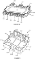
- the inverter 1 comprises a bottom 6 extending under the housing element 5-1 (FIG. figure 6 ).
- the inverter 1 further comprises, without limitation, two signal connectors 5-31, 5-32 and a power connector 5-4, mounted on the cover 5-2 of the housing 5.
- the signal connectors 5-31, 5-32 are intended to allow an exchange of data signals between the components of the inverter 1 and the outside of the inverter 1, for example with a vehicle controller.
- these signal connectors 5-31, 5-32 can be connected to the electronic control unit 20.
- the power connector 5-4 is intended to connect the inverter 1 to a power supply cable. , for example connected to the low-voltage on-board electrical network, in order to allow the power supply of the electronic control unit 20
- the housing member 5-1 is in the form of a one-piece piece made by molding an electrically insulating plastic material.
- the housing member 5-1 comprises a side wall 5-10 in the form of a U-shaped belt and support members 5-11 configured to receive the power electronics module 10 and the electronics unit. control 20 when mounted in said ESP interior space.
- the support elements 5-11 include 5-11A longitudinal members for receiving the body 100 of the power electronic module 10 and the electronic control unit.
- the housing member 5 comprises blocking walls 5-12 for mounting the phase conductors 111, 112, 113.
- the side wall 5-10 of the housing member 5-1 comprises a 5-10A material offset to its interior space (ESP) forming a connection area of the positive terminal and the negative terminal of the power supply battery. high tension.
- ESP interior space
- this material offset 5-10A overlaps the first electrical conductor 30 and the second electrical conductor 40 by revealing only the fastening element 301-C, 401-C on the outside of said side wall 5-10. central of each of the electrical conductors of potential 30, 40.
- the material 5-10A offset is formed so that the side wall 5-10 has a part of a U shape.
- the 5-10A material offset thus makes it possible to limit the area visible and accessible to an operator of the electrical conductors 30, 40 (connection zone) in order to reduce the risk of electric shock while allowing the use of electrical conductors 30, 40 extending along the entire length of one side of the housing 5.
- the fixing surfaces of the electrical conductors 30, 40 are in the interior space ESP defined by the side wall 5-10, they are no longer accessible. for an operator who thus sees the risk of receiving a considerably reduced electric shock.
- the extension of the side wall 5-10 of the housing 5 so as to cover the ends of the electrical conductors 30, 40 allows to release the so-called "extension" EXT areas above said ends, which advantageously allows to extend in particular the surface of the electronic card of the electronic control unit 20.
- the first electrical conductor 30 and the second electrical conductor 40 are first mounted on the insulating support bar 50 and their fastening elements 301, 401 are fixed to the positive external electrical terminals. 124 and the negative external electrical terminals 125 of the power electronic module 10 with four screws 131.
- the body 100 of the power electronics module 10 is then positioned in the housing element 5-1.
- Each phase conductor 111, 112, 113 is force-fitted, by sliding between each pair of walls 5-12A, 5-12B so as to be blocked by the gadroons between the first 5-12A wall and the second wall 5-12B of each pair of walls 5-12A, 5-12B, then screwed on the corresponding phase port 121, 122, 123 so as to connect it electrically to said phase ports 121, 122 , 123 of the power electronics module 10.
- the electronic control unit 20 is then mounted on the power electronics module 10.
- the cover 5-2 of the housing 5 is then attached to the housing element 5-1 so as to close the housing 5.
- the bottom 6 is fixed on the body of the power electronic module 10 so as to partially cover it, as shown in FIG. figure 6 , in particular to limit the risk for an operator to receive an electric shock by touching the body 100.
- phase conductors 111, 112, 113 of the inverter 1 can then be electrically connected to the electrical machine just as the electrical conductors 30, 40 can be electrically connected, via the positive and negative apparent terminals, respectively to the potential terminals. positive and negative of the vehicle's high voltage battery.
Abstract
L'invention a pour objet un équipement électrique (1), notamment pour véhicule électrique ou hybride, comprenant un boîtier (5), ledit boîtier (5) comprenant un élément de boîtier (5-1) comprenant une paroi latérale (5-10) et définissant un espace intérieur (ESP). La paroi latérale (5-10) de l'élément de boîtier (5-1) comprend un déport de matière (5-10A) vers son espace intérieur (ESP) formant une zone de connexion de la borne positive et de la borne négative de la source d'énergie électrique de sorte que ledit déport de matière (5-10A) chevauche le premier conducteur électrique (30) et le deuxième conducteur électrique (40) en ne laissant apparaître, de l'extérieur de ladite paroi latérale (5-10), que la borne apparente positive et la borne apparente négative.The invention relates to an electrical equipment (1), in particular for an electric or hybrid vehicle, comprising a housing (5), said housing (5) comprising a housing element (5-1) comprising a side wall (5-10). ) and defining an interior space (ESP). The side wall (5-10) of the housing element (5-1) comprises a material offset (5-10A) towards its interior space (ESP) forming a connection zone of the positive terminal and the negative terminal. the source of electrical energy so that said material offset (5-10A) overlaps the first electrical conductor (30) and the second electrical conductor (40) by not letting out from outside said side wall (5); -10), that the positive apparent terminal and the apparent negative terminal.
Description
La présente invention se rapporte au domaine des équipements électriques haute tension pour véhicules électriques et hybrides et concerne plus particulièrement un élément de boîtier pour un équipement électrique, notamment pour véhicule électrique et hybride.The present invention relates to the field of high voltage electrical equipment for electric and hybrid vehicles and more particularly relates to a housing element for electrical equipment, especially for electric and hybrid vehicles.
L'invention vise notamment à permettre une connexion fiable et sécurisée d'une batterie d'alimentation sur un équipement électrique.The invention aims in particular to allow a reliable and secure connection of a battery pack on an electrical equipment.
Comme cela est connu, un véhicule automobile électrique ou hybride comprend un système de motorisation électrique alimenté par une batterie d'alimentation haute tension via un réseau électrique embarqué haute tension et une pluralité d'équipements électriques auxiliaires alimentés par une batterie d'alimentation basse tension via un réseau électrique embarqué basse tension. La batterie d'alimentation haute tension assure une fonction d'alimentation en énergie du système de motorisation électrique permettant la propulsion du véhicule. Plus précisément, afin de commander la machine électrique entrainant les roues du véhicule, il est connu d'utiliser un onduleur permettant de convertir le courant continu fourni par la batterie d'alimentation haute tension en un ou plusieurs courants de commande alternatifs, par exemple sinusoïdaux.As is known, an electric or hybrid motor vehicle comprises an electric motor system powered by a high voltage power supply battery via a high voltage on-board electrical network and a plurality of auxiliary electrical equipment powered by a low voltage power supply battery. via a low voltage on-board electrical network. The high voltage power supply battery provides a power supply function of the electric drive system for propelling the vehicle. More specifically, in order to control the electrical machine driving the wheels of the vehicle, it is known to use an inverter for converting the direct current supplied by the high voltage power supply battery into one or more alternating control currents, for example sinusoidal currents. .
Dans une solution connue, l'onduleur se présente sous la forme d'un boîtier dans lequel sont montés un module électronique de puissance et une unité électronique de contrôle. Le module électronique de puissance comprend un corps comportant des composants électriques par lesquels passe l'énergie alimentant la machine électrique. L'unité électronique de contrôle comprend des composants électroniques permettant de contrôler le module électronique de puissance.In a known solution, the inverter is in the form of a housing in which are mounted an electronic power module and an electronic control unit. The electronic power module comprises a body having electrical components through which the energy supplying the electric machine passes. The electronic control unit comprises electronic components for controlling the electronic power module.
Par exemple, dans le cas où la machine électrique est un moteur électrique triphasé, le module électronique de puissance comprend trois conducteurs électriques, dits « conducteurs de phase », permettant de relier le module électronique de puissance au moteur électrique afin de le commander en utilisant trois courants dits « de phase » déphasés deux à deux, par exemple de 120°. Ces courants de phase sont générés par l'onduleur à partir du courant continu délivré par la batterie haute tension. Afin de connecter le module électronique de puissance à la batterie haute tension, l'onduleur comprend en outre un conducteur électrique destiné à être relié au potentiel positif de la batterie d'alimentation haute tension et un conducteur électrique destiné à être relié au potentiel négatif de la batterie d'alimentation haute tension.For example, in the case where the electric machine is a three-phase electric motor, the electronic power module comprises three electrical conductors, called "phase conductors", for connecting the electronic power module to the electric motor to control it using three currents called "phase" out of phase two by two, for example 120 °. These phase currents are generated by the inverter from the direct current delivered by the high voltage battery. In order to connect the electronic power module to the high voltage battery, the inverter further comprises an electrical conductor intended to be connected to the positive potential of the high voltage supply battery and an electrical conductor intended to be connected to the negative potential of the the high voltage power supply battery.
Un module électronique de puissance peut être fourni avec plusieurs bornes positives et plusieurs bornes négatives destinées à recevoir un signal électrique à partir d'une source d'énergie électrique. Typiquement, le signal électrique est modifié par des composants de puissance du module électronique de puissance pour être délivré en sortie du module électronique de puissance. Cependant, dans certaines applications, il n'est pas nécessaire de délivrer des signaux électriques différents sur les couples de bornes positive/négative. Il est alors nécessaire de relier chaque paire de borne positive/négative à la même source d'énergie électrique. Entre la source d'énergie électrique, il faut donc utiliser un connecteur pour chaque borne. Ce qui complique la connexion du module électronique de puissance à la source d'énergie électrique.An electronic power module may be provided with a plurality of positive terminals and a plurality of negative terminals for receiving an electrical signal from a source of electrical power. Typically, the electrical signal is modified by power components of the power electronic module to be delivered at the output of the electronic power module. However, in some applications, it is not necessary to provide different electrical signals on the positive / negative terminal pairs. It is then necessary to connect each pair of positive / negative terminals to the same source of electrical energy. Between the source of electrical energy, it is necessary to use a connector for each terminal. This complicates the connection of the electronic power module to the source of electrical energy.
De plus, l'intensité des courants pouvant circuler dans les conducteurs électriques reliés à la batterie d'alimentation haute tension étant relativement élevée, par exemple supérieur à 100 A, l'agencement desdits conducteurs électriques peut présenter un risque d'électrocution pour un opérateur qui manipulerait l'onduleur, notamment lors de la connexion ou la déconnexion de la batterie d'alimentation sur l'onduleur, ce qui présente un inconvénient majeur.In addition, since the intensity of the currents that can circulate in the electrical conductors connected to the high voltage supply battery is relatively high, for example greater than 100 A, the arrangement of said electrical conductors may present a risk of electrocution for an operator. which would manipulate the inverter, especially when connecting or disconnecting the battery pack on the inverter, which has a major drawback.
Il existe donc un besoin d'une solution simple de connexion d'un équipement électrique à une source d'énergie électrique.There is therefore a need for a simple solution for connecting an electrical equipment to a source of electrical energy.
L'invention concerne un équipement électrique, notamment pour véhicule électrique ou hybride, comprenant un boîtier, ledit boîtier comprenant un élément de boîtier comprenant une paroi latérale et définissant un espace intérieur dans lequel sont montés :
- un module électronique de puissance comprenant une pluralité de paires de bornes externes positive et négative destinées à échanger une énergie d'alimentation avec une source d'énergie électrique,
- une barre de connexion électrique comportant un premier conducteur électrique et un deuxième conducteur électrique, le premier conducteur électrique comprenant des bornes en contact avec les bornes positives du module électronique de puissance, de manière à mettre les bornes positives au même potentiel électrique par l'intermédiaire du premier conducteur électrique, le deuxième conducteur électrique comprenant des bornes en contact avec les bornes négatives du module électronique de puissance, de manière à mettre les bornes négatives au même potentiel électrique par l'intermédiaire du deuxième conducteur électrique, au moins une desdites bornes du premier conducteur électrique, dite « borne apparente positive », et au moins une desdites bornes du deuxième conducteur électrique, dite « borne apparente négative », étant adaptées pour être reliées respectivement à une borne positive et à une borne négative d'une source d'énergie électrique, équipement électrique dans lequel la paroi latérale de l'élément de boîtier comprend un déport de matière vers son espace intérieur formant une zone de connexion de la borne positive et de la borne négative de la source d'énergie électrique de sorte que ledit déport de matière chevauche le premier conducteur électrique et le deuxième conducteur électrique en ne laissant apparaître, de l'extérieur de ladite paroi latérale, que la borne apparente positive et la borne apparente négative.
- an electronic power module comprising a plurality of positive and negative external terminal pairs for exchanging power supply with a source of electrical energy,
- an electrical connection bar comprising a first electrical conductor and a second electrical conductor, the first electrical conductor comprising terminals in contact with the positive terminals of the power electronic module, so as to put the positive terminals at the same electrical potential via the first electrical conductor, the second electrical conductor comprising terminals in contact with the negative terminals of the power electronic module, so as to set the negative terminals to the same electrical potential via the second electrical conductor, at least one of said terminals of the first electrical conductor, said "positive apparent terminal", and at least one of said terminals of the second electrical conductor, said "negative apparent terminal", being adapted to be respectively connected to a positive terminal and a negative terminal of a source of electrical energy team electrical system in which the side wall of the housing comprises an offset of material towards its interior space forming a connection zone of the positive terminal and the negative terminal of the electrical energy source so that said material offset overlaps the first electrical conductor and the second electrical conductor does not. revealing, from the outside of said side wall, that the positive apparent terminal and the negative apparent terminal.
Ainsi, lorsque le module électronique de puissance et les conducteurs électriques sont montés dans l'élément de boîtier, la paroi latérale forme une ceinture entourant le module électronique de puissance et recouvrant en partie le premier conducteur électrique et le deuxième conducteur électrique de manière à ne laisser apparaître, à l'extérieur de ladite paroi latérale, qu'un seul élément de fixation de chacun des conducteurs électriques à une borne positive ou négative de la source d'énergie électrique, par exemple une batterie d'alimentation haute tension. La zone de connexion ainsi délimitée présente une surface restreinte qui réduit les risques de choc électrique pour un opérateur. Plus précisément, une première partie des bornes du premier conducteur sont à l'extérieur du boiter de manière à former au moins une borne externe de l'équipement électrique pour une connexion avec la source d'énergie électrique et une deuxième partie des bornes du premier conducteur sont à l'intérieur du boitier. De même, une première partie des bornes du deuxième conducteur sont à l'extérieur du boiter de manière à former au moins une borne externe de l'équipement électrique pour une connexion avec la source d'énergie électrique et une deuxième partie des bornes du deuxième conducteur sont à l'intérieur du boitier. L'agencement de l'espace intérieur défini par la paroi latérale permet ainsi de protéger la deuxième parties des bornes des conducteurs électriques de l'extérieur afin d'éviter à un opérateur de les toucher et de recevoir un choc électrique. Autrement dit, le déport de matière permet de ne faire apparaître de l'extérieur que la portion utile des conducteurs électriques de potentiel afin de réduire les risques de choc électrique. Les deuxièmes parties des bornes des conducteurs électriques sont dans l'espace intérieur du boitier, contrairement à l'art antérieur où elles sont à l'extérieur du boitier pour pouvoir être connectées à la source d'énergie électrique. De plus, un tel agencement de la paroi latérale permet d'augmenter le volume de l'espace interne de l'élément de boîtier de sorte qu'une unité électronique de contrôle peut s'étendre non seulement au-dessus du module électronique de puissance, mais également au-dessus du conducteur électrique de potentiel positif et du conducteur électrique de potentiel négatif. Dans l'équipement électrique selon l'invention, la barre de connexion électrique permet de relier ensemble d'une part, les bornes positives du module électronique de puissance, et d'autre part les bornes négatives du module électronique de puissance. Ainsi, il n'est pas nécessaire d'avoir un conducteur pour chaque borne positive ou négative du module électronique de puissance. Il suffit de connecter la borne apparente positive avec la borne positive de la source d'énergie électrique et la borne apparente négative avec la borne négative de la source d'énergie électrique de sorte que les bornes du module électronique de puissance reçoivent, via le premier conducteur électrique et le deuxième conducteur électrique le signal électrique généré par la source d'énergie électrique. Il est donc facile de connecter le module électronique de puissance à la source d'énergie électrique. En outre, on évite l'utilisation de plusieurs paires de connecteurs entre le module électronique de puissance et la source d'énergie électrique, ce qui réduit la résistance d'entrée du module électronique de puissance.Thus, when the electronic power module and the electrical conductors are mounted in the housing element, the side wall forms a belt surrounding the electronic power module and partly covering the first electrical conductor and the second electrical conductor so as not to revealing, on the outside of said lateral wall, only one fixing element of each of the electrical conductors to a positive or negative terminal of the source of electrical energy, for example a high voltage supply battery. The connection area thus delimited has a restricted area which reduces the risk of electric shock for an operator. More specifically, a first portion of the terminals of the first conductor are outside the limp so as to form at least one external terminal of the electrical equipment for a connection with the source of electrical energy and a second part of the terminals of the first driver are inside the case. Similarly, a first part of the terminals of the second conductor are outside the limp so as to form at least one external terminal of the electrical equipment for a connection with the source of electrical energy and a second part of the terminals of the second driver are inside the case. The arrangement of the interior space defined by the side wall thus makes it possible to protect the second parts of the terminals of the electrical conductors from the outside so as to prevent an operator from touching them and receiving an electric shock. In other words, the material offset makes it possible to reveal from the outside only the useful portion of the potential electrical conductors to reduce the risk of electric shock. The second parts of the terminals of the electrical conductors are in the interior space of the housing, unlike the prior art where they are outside the housing to be connected to the source of electrical energy. In addition, such an arrangement of the side wall makes it possible to increase the volume of the internal space of the housing element so that an electronic control unit can extend not only above the electronic power module. , but also above the positive potential electrical conductor and the negative potential electrical conductor. In the electrical equipment according to the invention, the electrical connection bar makes it possible to connect together, on the one hand, the positive terminals of the electronic power module, and on the other hand the negative terminals of the electronic power module. Thus, it is not necessary to have a conductor for each positive or negative terminal of the electronic power module. Just connect the positive apparent terminal with the positive terminal of the electrical power source and the negative apparent terminal with the negative terminal of the electrical power source so that the terminals of the electronic power module receive, via the first driver electrical and the second electrical conductor the electrical signal generated by the source of electrical energy. It is therefore easy to connect the electronic power module to the source of electrical energy. In addition, it avoids the use of several pairs of connectors between the electronic power module and the power source, which reduces the input resistance of the electronic power module.
De préférence, la paroi latérale présente au moins en partie une forme de U, le déport de matière formant la zone de connexion correspondant à l'évidemment situé entre les branches du U.Preferably, the side wall has at least partly a U-shape, the material offset forming the connection zone corresponding to the recess located between the branches of the U.
De manière avantageuse, l'élément de boîtier comprend en outre une pluralité d'éléments de support reliant entre elles une pluralité de portions de la paroi latérale et permettant notamment le support du module électronique de puissance, du premier conducteur électrique et du deuxième conducteur électrique.Advantageously, the housing element further comprises a plurality of support elements interconnecting a plurality of portions of the side wall and in particular allowing the support of the electronic power module, the first electrical conductor and the second electrical conductor. .
De préférence encore, l'élément de boîtier est monobloc, ce qui le rend solide, aisé à manipuler lors de l'assemblage et aisé à fabriquer, notamment par surmoulage.More preferably, the housing member is integral, which makes it solid, easy to handle during assembly and easy to manufacture, in particular by overmolding.
Selon un aspect de l'invention, l'élément de boîtier étant réalisé en un matériau plastique, ce qui le rend léger, solide et aisé à fabriquer, notamment par surmoulage.According to one aspect of the invention, the housing member being made of a plastic material, which makes it light, strong and easy to manufacture, in particular by overmolding.
Avantageusement, la barre de connexion électrique comprend en outre une barre de fixation sur laquelle sont montés le premier conducteur électrique et le deuxième conducteur électrique.Advantageously, the electrical connection bar further comprises a fixing bar on which are mounted the first electrical conductor and the second electrical conductor.
Selon un aspect de l'invention, l'équipement électrique comprend en outre un couvercle fermant une face de la paroi latérale de l'élément de boîtier.According to one aspect of the invention, the electrical equipment further comprises a cover closing one side of the side wall of the housing member.
De manière avantageuse, l'équipement électrique comprend en outre une unité électronique de contrôle, ladite unité électronique de contrôle étant montée dans l'espace intérieur défini par la paroi latérale de l'élément de boîtier et étant configurée pour contrôler le module électronique de puissance, notamment afin qu'il convertisse un courant continu en au moins un courant alternatif.Advantageously, the electrical equipment further comprises an electronic control unit, said electronic control unit being mounted in the interior space defined by the side wall of the housing element and being configured to control the electronic power module. , in particular so that it converts a direct current into at least one alternating current.
Dans une forme de réalisation, l'équipement électrique est un onduleur destiné à être électriquement connecté, d'une part, à une machine électrique, notamment d'un véhicule électrique ou hybride et, d'autre part, à une batterie d'alimentation haute tension, notamment d'un véhicule électrique ou hybride.In one embodiment, the electrical equipment is an inverter intended to be electrically connected, on the one hand, to an electric machine, in particular an electric or hybrid vehicle and, on the other hand, to a battery pack high voltage, including an electric or hybrid vehicle.
Selon un aspect de l'invention, le module électronique de puissance est apte à convertir un courant continu en une pluralité de courants alternatifs dits « courants de phase ». Par les termes « module électronique de puissance apte à convertir un courant continu en une pluralité de courants alternatifs », on entend que le module électronique de puissance peut être configuré pour convertir un courant continu en une pluralité de courant alternatifs et/ou pour convertir une pluralité de courant alternatifs en un courant continu.According to one aspect of the invention, the electronic power module is able to convert a direct current into a plurality of alternating currents known as "phase currents". By the term "electronic power module adapted to convert a direct current into a plurality of alternating currents", it is meant that the electronic power module can be configured to convert a direct current into a plurality of alternating currents and / or to convert a plurality of alternating current in a direct current.
De manière préférée, le module de puissance comprend un corps.Preferably, the power module comprises a body.
Selon un aspect de l'invention, le premier conducteur électrique et le deuxième conducteur électrique sont montés sur le corps du module électronique de puissance.According to one aspect of the invention, the first electrical conductor and the second electrical conductor are mounted on the body of the electronic power module.
L'invention concerne aussi un véhicule électrique ou hybride comprenant une machine électrique, par exemple une machine de motorisation, alimentée par une batterie d'alimentation haute tension via un réseau électrique embarqué haute tension et un équipement électrique, tel que présenté précédemment, connecté à ladite machine électrique.The invention also relates to an electric or hybrid vehicle comprising an electric machine, for example a motorization machine, powered by a high-voltage power supply battery via a high-voltage on-board electrical network and electrical equipment, as presented previously, connected to said electric machine.
L'invention sera mieux comprise à la lecture de la description qui va suivre, donnée uniquement à titre d'exemple, et se référant aux dessins annexés donnés à titre d'exemples non limitatifs, dans lesquels des références identiques sont données à des objets semblables et sur lesquels :
- la
figure 1 est une vue en perspective d'une forme de réalisation d'un onduleur selon l'invention, - la
figure 2A est une vue partielle en perspective de l'ensemble formé du module électronique de puissance, de l'unité électronique de contrôle, du premier conducteur électrique de potentiel positif, du premier conducteur électrique de potentiel négatif et de la barre de fixation de l'onduleur de lafigure 1 , - la
figure 2B est une vue partielle en perspective du module électronique de puissance, - la
figure 3 est une vue en perspective de dessus de l'élément de boîtier de l'onduleur de la figure, - la
figure 4 est une vue en perspective de dessous de l'élément de boîtier de l'onduleur de lafigure 1 , - la
figure 5 est une vue en perspective de dessus de l'élément de boitier desfigures 3 et4 dans lequel est monté l'ensemble de lafigure 2A et trois conducteurs de phase, - la
figure 6 est une vue en perspective de dessous de l'ensemble illustré à lafigure 5 , - la
figure 7 est une vue de dessus partielle de l'onduleur de lafigure 1 montrant le montage de l'unité électronique de contrôle sur le module électronique de puissance.
- the
figure 1 is a perspective view of an embodiment of an inverter according to the invention, - the
Figure 2A is a partial perspective view of the assembly formed of the electronic power module, the electronic control unit, the first positive potential electrical conductor, the first negative potential electrical conductor and the inverter fixing bar. of thefigure 1 , - the
Figure 2B is a partial perspective view of the electronic power module, - the
figure 3 is a perspective view from above of the inverter housing element of the figure, - the
figure 4 is a perspective view from below of the inverter case element of thefigure 1 , - the
figure 5 is a perspective view from above of the box element of thefigures 3 and4 in which is mounted the whole of theFigure 2A and three phase drivers, - the
figure 6 is a perspective view from below of the set shown in thefigure 5 , - the
figure 7 is a partial top view of the inverter of thefigure 1 showing the mounting of the electronic control unit on the electronic power module.
Il faut noter que les figures exposent l'invention de manière détaillée pour mettre en oeuvre l'invention, lesdites figures pouvant bien entendu servir à mieux définir l'invention le cas échéant.It should be noted that the figures disclose the invention in detail to implement the invention, said figures can of course be used to better define the invention where appropriate.
Dans la description qui sera faite ci-après, l'invention sera décrite dans son application à un véhicule automobile électrique ou hybride sans que cela ne soit limitatif de la portée de la présente invention.In the description which will be given below, the invention will be described in its application to an electric or hybrid motor vehicle without this being limiting to the scope of the present invention.
Dans l'exemple décrit ci-après, le véhicule comprend notamment une machine électrique, un équipement électrique se présentant sous la forme d'un onduleur, une batterie d'alimentation haute tension, un réseau électrique embarqué haute tension, une batterie d'alimentation basse tension, un réseau électrique embarqué basse tension et une pluralité d'équipements électriques auxiliaires.In the example described below, the vehicle comprises in particular an electric machine, an electrical equipment in the form of an inverter, a high voltage power supply battery, a high voltage on-board electrical network, a battery pack low voltage, a low voltage onboard electrical network and a plurality of auxiliary electrical equipment.
L'équipement électrique selon l'invention est décrit ci-après dans sa mise en oeuvre pour un onduleur, sans toutefois que cela ne limite la portée de la présente invention. On notera ainsi que l'équipement électrique pourrait être autre chose qu'un onduleur, par exemple un chargeur ou un convertisseur DCDC embarqués dans le véhicule.The electrical equipment according to the invention is described below in its implementation for an inverter, without however limiting the scope of the present invention. It should be noted that the electrical equipment could be anything other than an inverter, for example a charger or a DCDC converter embedded in the vehicle.
Le réseau électrique embarqué basse tension relie la batterie d'alimentation basse tension et la pluralité d'équipements électriques auxiliaires afin que la batterie d'alimentation basse tension alimente lesdits équipements électriques auxiliaires, tels que des calculateurs embarqués, des moteurs de lève-vitres, un système multimédia, etc. La batterie d'alimentation basse tension délivre typiquement par exemple une tension de l'ordre de 12 V, 24 V ou 48 V. La recharge de la batterie basse tension est réalisée à partir de la batterie haute tension via un convertisseur de tension continue en tension continue, appelé communément convertisseur continu-continu.The low voltage on-board electrical network connects the low-voltage battery and the plurality of auxiliary electrical equipment so that the low-voltage battery supply supplies said auxiliary electrical equipment, such as on-board computers, window motors, a multimedia system, etc. The low voltage supply battery typically delivers, for example, a voltage of the order of 12 V, 24 V or 48 V. The low voltage battery is recharged from the high voltage battery via a DC voltage converter. DC voltage, commonly called DC-DC converter.
Le réseau électrique embarqué haute tension relie la batterie d'alimentation haute tension et l'onduleur afin que la batterie d'alimentation haute tension assure une fonction d'alimentation en énergie de la machine électrique via l'onduleur. La batterie d'alimentation haute tension délivre typiquement une tension comprise entre 100 V et 900 V, de préférence entre 100 V et 500 V. La recharge en énergie électrique de la batterie d'alimentation haute tension est réalisée en la connectant, via le réseau électrique haute tension continue du véhicule, à un réseau électrique externe, par exemple le réseau électrique alternatif domestique.The high voltage on-board electrical network connects the high voltage battery and the inverter so that the high voltage power supply battery provides a power supply function of the electrical machine via the inverter. The high-voltage power supply battery typically delivers a voltage of between 100 V and 900 V, preferably between 100 V and 500 V. The electrical energy recharge of the high-voltage power supply battery is achieved by connecting it via the network. continuous high voltage electrical vehicle, to an external electrical network, for example the domestic alternative power grid.
La machine électrique est une machine électrique tournante, de préférence destinée à entrainer les roues du véhicule à partir de l'énergie fournie par la batterie d'alimentation haute-tension. Plus précisément, la machine électrique est une machine électrique à courant alternatif alimentée par une source de courants polyphasés. Par exemple, la machine électrique peut être un moteur à courant alternatif. Dans l'exemple préféré décrit ci-après, la machine électrique est alimentée par une source de courants triphasés sans que cela ne soit limitatif de la portée de la présente invention.The electric machine is a rotating electrical machine, preferably for driving the wheels of the vehicle from the energy supplied by the high-voltage battery. More specifically, the electrical machine is an AC electric machine powered by a source of polyphase currents. For example, the electric machine may be an AC motor. In the preferred example described below, the electrical machine is powered by a three-phase current source without this being limited by the scope of the present invention.
Dans cet exemple, la commande de la machine électrique est réalisée au moyen de l'onduleur. Ledit onduleur permet de convertir le courant continu fourni par la batterie d'alimentation haute tension en trois courants de commande alternatifs, par exemple sinusoïdaux. Autrement dit, l'onduleur a pour fonction de transformer le courant continu délivré en entrée par la batterie d'alimentation haute tension en trois courants de phase permettant de commander la machine électrique. A l'inverse, dans un autre mode de fonctionnement, la machine électrique peut également fournir trois courants alternatifs à l'onduleur afin que ledit onduleur les transforme en un courant continu permettant de charger la batterie d'alimentation haute-tension.In this example, the control of the electric machine is carried out by means of the inverter. Said inverter makes it possible to convert the direct current supplied by the high voltage supply battery into three alternating control currents, for example sinusoidal currents. In other words, the function of the inverter is to transform the DC current delivered to the input by the high voltage supply battery into three phase currents for controlling the electric machine. Conversely, in another mode of operation, the electric machine can also provide three alternating currents to the inverter so that said inverter transforms them into a direct current for charging the high-voltage battery.
Dans l'exemple des
En référence aux
En référence à la
En référence aux
En référence à la
Toujours en référence à la
Chaque conducteur de phase 111, 112, 113 permet de connecter électriquement une phase de la machine électrique commandée par l'onduleur 1 avec le module électronique de puissance 10. On notera que, dans une autre forme de réalisation, l'onduleur 1 pourrait comprendre un nombre de conducteurs de phase 111, 112, 113 différent, notamment un nombre fonction du nombre de phases de la machine électrique commandée par l'onduleur 1. Chaque connecteur de phase 111, 112, 113 est monté sur un port de phase 121, 122, 123 correspondant du module électronique de puissance 10 par l'intermédiaire d'un moyen de fixation, par exemple une vis (non représentée). Chaque conducteur de phase 111, 112, 113 traverse une ouverture du boîtier 5 pour permettre de relier l'onduleur 1 à la machine électrique et notamment permettre la circulation des courants alternatifs entre le module électronique de puissance 10 et la machine électrique.Each
L'unité électronique de contrôle 20 comprend des composants pour contrôler les composants du module électronique de puissance 10. Plus précisément, l'unité électronique de contrôle 20 commande le module électronique de puissance 10 afin qu'il réalise la fonction de conversion du courant continu reçu de la batterie haute tension, définissant une tension continue entre le premier conducteur électrique 30 et le deuxième conducteur électrique 40, en trois courants de phase alternatifs de commande du moteur (ou vice-et-versa).The
Comme illustré sur la
En référence désormais aux
Toujours dans cet exemple, l'élément de boîtier 5 comprend des parois de blocage 5-12 permettant de monter les conducteurs de phase 111, 112, 113.Still in this example, the housing member 5 comprises blocking walls 5-12 for mounting the
La paroi latérale 5-10 de l'élément de boîtier 5-1 comprend un déport de matière 5-10A vers son espace intérieur (ESP) formant une zone de connexion de la borne positive et de la borne négative de la batterie d'alimentation haute tension.The side wall 5-10 of the housing member 5-1 comprises a 5-10A material offset to its interior space (ESP) forming a connection area of the positive terminal and the negative terminal of the power supply battery. high tension.
Comme illustré sur les
Dans l'exemple illustré et de manière non limitative, le déport de matière 5-10A est formé de sorte que la paroi 5-10 latérale présente en partie une forme de U. L'évidemment formé entre les branches du U, délimité par le déport de matière 5-10A de la paroi latérale 5-10 vers l'espace intérieur ESP, constituant la zone de connexion des bornes positives et négative de la batterie d'alimentation haute tension.In the illustrated example and in a nonlimiting manner, the material 5-10A offset is formed so that the side wall 5-10 has a part of a U shape. The recess formed between the branches of the U, delimited by the material offset 5-10A from the side wall 5-10 to the ESP interior space, constituting the connection area of the positive and negative terminals of the high voltage supply battery.
Le déport de matière 5-10A permet ainsi de limiter la zone visible et accessible à un opérateur des conducteurs électriques 30, 40 (zone de connexion) afin de réduire le risque de choc électrique tout en permettant l'utilisation de conducteurs électriques 30, 40 s'étendant sur toute la longueur d'un côté du boîtier 5. En effet, les surfaces de fixation des conducteurs électriques 30, 40 se trouvant dans l'espace intérieur ESP défini par la paroi latérale 5-10, elles ne sont plus accessibles pour un opérateur qui voit ainsi le risque de recevoir un choc électrique considérablement réduit. De plus, l'extension de la paroi latérale 5-10 du boîtier 5 de sorte à recouvrir les extrémités des conducteurs électriques 30, 40 permet de libérer des zones dites « d'extension » EXT au-dessus desdites extrémités, ce qui permet avantageusement d'étendre notamment la surface de la carte électronique de l'unité électronique de contrôle 20.The 5-10A material offset thus makes it possible to limit the area visible and accessible to an operator of the
Lors de l'assemblage de l'onduleur 1, le premier conducteur électrique 30 et le deuxième conducteur électrique 40 sont tout d'abord montés sur la barre de support isolante 50 puis leurs éléments de fixation 301, 401 sont fixés aux bornes électriques externes positives 124 et sur les bornes électriques externes négatives 125 du module électronique de puissance 10 à l'aide de quatre vis 131.During the assembly of the
Le corps 100 du module électronique de puissance 10 est ensuite positionné dans l'élément de boîtier 5-1.The
Chaque conducteur de phase 111, 112, 113 est monté à force, par glissement entre chaque paire de parois 5-12A, 5-12B de sorte à être bloqués par les godrons entre la première paroi 5-12A et la deuxième paroi 5-12B de chaque paire de parois 5-12A, 5-12B, puis vissé sur le port de phase 121, 122, 123 correspondant de manière à le relier électriquement auxdits ports de phase 121, 122, 123 du module électronique de puissance 10.Each
L'unité électronique de contrôle 20 est ensuite montée sur le module électronique de puissance 10. Le couvercle 5-2 du boîtier 5 est ensuite être fixé sur l'élément de boîtier 5-1 de manière à fermer le boîtier 5. De même, le fond 6 est fixé sur le corps du module électronique de puissance 10 de manière à le recouvrir en partie, comme illustré sur la
Les conducteurs de phase 111, 112, 113 de l'onduleur 1 peuvent ensuite être connectés électriquement à la machine électrique de même que les conducteurs électriques 30, 40 peuvent être connectés électriquement, via les bornes apparentes positive et négative, respectivement aux bornes de potentiel positif et négatif de la batterie d'alimentation haute tension du véhicule.The
L'invention ne se limite pas au seul exemple décrit ci-dessus. Les figures représentent un exemple particulier de réalisation qui combine plusieurs modes de réalisation. Cependant, les caractéristiques liées aux modes de réalisation peuvent-être indépendantes entre elles d'un mode à l'autre, ou combinées entre elles, comme cela ressort des revendications.The invention is not limited to the single example described above. The figures represent a particular embodiment which combines several embodiments. However, the features related to the embodiments may be independent of each other from one mode to another, or combined with one another, as is apparent from the claims.
Claims (10)
Applications Claiming Priority (1)
| Application Number | Priority Date | Filing Date | Title |
|---|---|---|---|
| FR1762950A FR3076175B1 (en) | 2017-12-22 | 2017-12-22 | REMOTE WALL ELECTRICAL EQUIPMENT |
Publications (2)
| Publication Number | Publication Date |
|---|---|
| EP3501908A1 true EP3501908A1 (en) | 2019-06-26 |
| EP3501908B1 EP3501908B1 (en) | 2020-09-09 |
Family
ID=61224161
Family Applications (1)
| Application Number | Title | Priority Date | Filing Date |
|---|---|---|---|
| EP18210582.5A Active EP3501908B1 (en) | 2017-12-22 | 2018-12-05 | Electrical equipment with offset wall |
Country Status (5)
| Country | Link |
|---|---|
| US (2) | US10966336B2 (en) |
| EP (1) | EP3501908B1 (en) |
| CN (1) | CN109962193B (en) |
| FR (1) | FR3076175B1 (en) |
| HU (1) | HUE051822T2 (en) |
Families Citing this family (7)
| Publication number | Priority date | Publication date | Assignee | Title |
|---|---|---|---|---|
| USD954667S1 (en) | 2017-01-13 | 2022-06-14 | Wolfspeed, Inc. | Power module |
| USD929462S1 (en) * | 2018-06-04 | 2021-08-31 | Semikron Elektronik Gmbh & Co. Kg | Module |
| JP7087834B2 (en) * | 2018-08-28 | 2022-06-21 | トヨタ自動車株式会社 | In-vehicle structure of electrical equipment |
| USD903590S1 (en) * | 2018-09-12 | 2020-12-01 | Cree Fayetteville, Inc. | Power module |
| USD962950S1 (en) * | 2019-12-18 | 2022-09-06 | Assa Abloy Ab | Combined cover and base assembly for a control panel for an access control system |
| USD963656S1 (en) | 2019-12-18 | 2022-09-13 | Assa Abloy Ab | Control panel for an access control system |
| USD979565S1 (en) | 2019-12-18 | 2023-02-28 | Assa Abloy Ab | Control panel |
Citations (5)
| Publication number | Priority date | Publication date | Assignee | Title |
|---|---|---|---|---|
| EP1870969A1 (en) * | 2006-06-22 | 2007-12-26 | Omron Corporation | Electronic equipment and method of manufacturing the electronic equipment |
| FR2979177A1 (en) * | 2011-08-19 | 2013-02-22 | Valeo Sys Controle Moteur Sas | POWER BLOCK FOR ELECTRIC VEHICLE INVERTER |
| WO2013102720A1 (en) * | 2012-01-05 | 2013-07-11 | Valeo Equipements Electriques Moteur | Device for assembling capacitors for an electronic converter |
| EP3002999A1 (en) * | 2014-09-30 | 2016-04-06 | Valeo Systèmes De Contrôle Moteur | Modular electrical device in which each module is intended for being secured to a respective mounting, and electrical system comprising such an electrical device |
| WO2017081245A1 (en) * | 2015-11-13 | 2017-05-18 | Valeo Systemes De Controle Moteur | Electrical busbar |
Family Cites Families (36)
| Publication number | Priority date | Publication date | Assignee | Title |
|---|---|---|---|---|
| US5748456A (en) * | 1995-11-24 | 1998-05-05 | Asea Brown Boveri Ag | Power semiconductor module system |
| US5898128A (en) * | 1996-09-11 | 1999-04-27 | Motorola, Inc. | Electronic component |
| KR200200492Y1 (en) * | 2000-05-10 | 2000-10-16 | 엘지산전주식회사 | A thermal overload relay with an independent install equipment and security cover |
| WO2002082543A1 (en) * | 2001-03-30 | 2002-10-17 | Hitachi, Ltd. | Semiconductor device |
| JP4155048B2 (en) * | 2003-02-14 | 2008-09-24 | 住友電装株式会社 | Power module and manufacturing method thereof |
| US6987670B2 (en) * | 2003-05-16 | 2006-01-17 | Ballard Power Systems Corporation | Dual power module power system architecture |
| JP5041798B2 (en) * | 2006-12-15 | 2012-10-03 | 三菱電機株式会社 | Semiconductor device |
| JP4436843B2 (en) * | 2007-02-07 | 2010-03-24 | 株式会社日立製作所 | Power converter |
| JP2008228398A (en) * | 2007-03-09 | 2008-09-25 | Toyota Motor Corp | Power conversion device |
| JP5108421B2 (en) * | 2007-09-05 | 2012-12-26 | 株式会社ケーヒン | Inverter device having split module terminals |
| EP2208225B1 (en) * | 2007-11-13 | 2018-10-10 | Siemens Aktiengesellschaft | Power semiconductor module |
| EP2099121B1 (en) * | 2008-03-04 | 2017-10-18 | Kabushiki Kaisha Toyota Jidoshokki | Power converter apparatus |
| JP4580997B2 (en) * | 2008-03-11 | 2010-11-17 | 日立オートモティブシステムズ株式会社 | Power converter |
| JP5002568B2 (en) * | 2008-10-29 | 2012-08-15 | 日立オートモティブシステムズ株式会社 | Power converter |
| WO2010131679A1 (en) * | 2009-05-14 | 2010-11-18 | ローム株式会社 | Semiconductor device |
| CN201478200U (en) * | 2009-08-25 | 2010-05-19 | 东莞市宇韵自动化器材有限公司 | Relay with electric shock protection |
| JP5740986B2 (en) * | 2010-03-17 | 2015-07-01 | 株式会社安川電機 | Power converter |
| JP2012005301A (en) * | 2010-06-18 | 2012-01-05 | Fuji Electric Co Ltd | Power semiconductor module |
| US9685888B2 (en) * | 2011-06-10 | 2017-06-20 | Fuji Electric Co., Ltd. | Semiconductor module, upper and lower arm kit, and three-level inverter |
| JP5831626B2 (en) * | 2012-03-28 | 2015-12-09 | 富士電機株式会社 | Semiconductor device and manufacturing method of semiconductor device |
| CN104170085B (en) * | 2012-03-28 | 2017-05-10 | 富士电机株式会社 | Semiconductor device |
| JP5796257B2 (en) * | 2012-05-31 | 2015-10-21 | アイシン・エィ・ダブリュ株式会社 | Inverter device |
| JP6044321B2 (en) * | 2012-12-19 | 2016-12-14 | 富士電機株式会社 | Semiconductor module |
| JP6171586B2 (en) * | 2013-06-04 | 2017-08-02 | 富士電機株式会社 | Semiconductor device |
| JP6112073B2 (en) * | 2014-06-20 | 2017-04-12 | 株式会社豊田自動織機 | Semiconductor device |
| JP6382097B2 (en) * | 2014-12-24 | 2018-08-29 | 株式会社 日立パワーデバイス | Semiconductor power module and power converter using the same |
| JP6262159B2 (en) * | 2015-01-14 | 2018-01-17 | 矢崎総業株式会社 | Fuse unit |
| JP6232001B2 (en) * | 2015-01-14 | 2017-11-15 | 矢崎総業株式会社 | Fuse unit |
| US9431311B1 (en) * | 2015-02-19 | 2016-08-30 | Semiconductor Components Industries, Llc | Semiconductor package with elastic coupler and related methods |
| US10091903B2 (en) * | 2015-02-19 | 2018-10-02 | Hitachi Automotive Systems, Ltd. | Power conversion device having bus bar with improved vibration resistance |
| JP6511979B2 (en) * | 2015-06-18 | 2019-05-15 | 富士電機株式会社 | Semiconductor device and method of manufacturing semiconductor device |
| JP6682824B2 (en) * | 2015-11-25 | 2020-04-15 | 富士電機株式会社 | Semiconductor device |
| US20190206810A1 (en) * | 2016-08-22 | 2019-07-04 | Neturen Co., Ltd. | Power semiconductor module, snubber circuit, and induction heating power supply apparatus |
| WO2018135176A1 (en) * | 2017-01-17 | 2018-07-26 | 富士電機株式会社 | Semiconductor device |
| US10779445B2 (en) * | 2018-03-23 | 2020-09-15 | Chongqing Jinkang New Energy Vehicle Co., Ltd. | Inverter module having multiple half-bridge modules for a power converter of an electric vehicle |
| US10778117B2 (en) * | 2018-04-17 | 2020-09-15 | Chongqing Jinkang New Energy Vehicle Co., Ltd. | Inverter module of an electric vehicle |
-
2017
- 2017-12-22 FR FR1762950A patent/FR3076175B1/en active Active
-
2018
- 2018-12-05 EP EP18210582.5A patent/EP3501908B1/en active Active
- 2018-12-05 HU HUE18210582A patent/HUE051822T2/en unknown
- 2018-12-20 US US16/226,837 patent/US10966336B2/en active Active
- 2018-12-21 CN CN201811572083.6A patent/CN109962193B/en active Active
-
2021
- 2021-02-25 US US17/185,141 patent/US11844185B2/en active Active
Patent Citations (5)
| Publication number | Priority date | Publication date | Assignee | Title |
|---|---|---|---|---|
| EP1870969A1 (en) * | 2006-06-22 | 2007-12-26 | Omron Corporation | Electronic equipment and method of manufacturing the electronic equipment |
| FR2979177A1 (en) * | 2011-08-19 | 2013-02-22 | Valeo Sys Controle Moteur Sas | POWER BLOCK FOR ELECTRIC VEHICLE INVERTER |
| WO2013102720A1 (en) * | 2012-01-05 | 2013-07-11 | Valeo Equipements Electriques Moteur | Device for assembling capacitors for an electronic converter |
| EP3002999A1 (en) * | 2014-09-30 | 2016-04-06 | Valeo Systèmes De Contrôle Moteur | Modular electrical device in which each module is intended for being secured to a respective mounting, and electrical system comprising such an electrical device |
| WO2017081245A1 (en) * | 2015-11-13 | 2017-05-18 | Valeo Systemes De Controle Moteur | Electrical busbar |
Also Published As
| Publication number | Publication date |
|---|---|
| EP3501908B1 (en) | 2020-09-09 |
| CN109962193A (en) | 2019-07-02 |
| FR3076175A1 (en) | 2019-06-28 |
| HUE051822T2 (en) | 2021-03-29 |
| FR3076175B1 (en) | 2020-01-10 |
| US11844185B2 (en) | 2023-12-12 |
| US20190200475A1 (en) | 2019-06-27 |
| CN109962193B (en) | 2023-09-29 |
| US10966336B2 (en) | 2021-03-30 |
| US20210185845A1 (en) | 2021-06-17 |
Similar Documents
| Publication | Publication Date | Title |
|---|---|---|
| EP3501908B1 (en) | Electrical equipment with offset wall | |
| EP3501907B1 (en) | Housing element of electrical equipment, in particular comprising u-shaped magnetic parts | |
| EP3501910A1 (en) | Housing element for electrical equipment | |
| FR3064832A1 (en) | THREE PHASE AND SINGLE PHASE ELECTRIC CHARGER SYSTEM FOR ELECTRIC OR HYBRID VEHICLE | |
| EP3668288A1 (en) | Electrical device comprising an insulating film | |
| EP3476665B1 (en) | Electrical insulation bar, in particular for a power electronics module of an inverter | |
| EP3727944B1 (en) | Electrically conductive part for an electrical assembly | |
| FR3027854B1 (en) | ELECTRICAL CONNECTION CABLE FOR CHARGING AN ENERGY ACCUMULATOR OF A MOTOR VEHICLE | |
| FR3076063A1 (en) | ELECTRICALLY INSULATING MONOBLOCK FIXING BAR FOR VEHICLE ELECTRICAL EQUIPMENT | |
| EP3727943B1 (en) | Electrical connection bar for an electrical assembly | |
| WO2012072913A1 (en) | Electrical connector socket, and associated connector | |
| EP3492301B1 (en) | Electrical device for an electric or hybrid vehicle | |
| EP3668289B1 (en) | Electrical device comprising a folded-on insulating film | |
| EP3474025A1 (en) | Sensor for measuring an output current of an electrical system | |
| WO2019122289A1 (en) | Electrical connection bar | |
| FR3064126A1 (en) | ELECTRICAL SYSTEM FOR MOTOR VEHICLE WITH ELECTRIC OR HYBRID MOTOR | |
| EP3331336B1 (en) | Compact power electronics system for electric powertrain | |
| WO2023094701A1 (en) | Power converter with a decoupling module | |
| WO2016079300A2 (en) | Power electronic module, dual voltage converter and dual-voltage polyphase rotating electric machine of a motor vehicle | |
| FR3083375A1 (en) | GRID FOR INTERFACE CONNECTOR | |
| FR3140718A1 (en) | Electrical connection device between an electrical machine and a power electronics module | |
| WO2018219905A1 (en) | Dc-dc converter for an electric or hybrid vehicle |
Legal Events
| Date | Code | Title | Description |
|---|---|---|---|
| PUAI | Public reference made under article 153(3) epc to a published international application that has entered the european phase |
Free format text: ORIGINAL CODE: 0009012 |
|
| STAA | Information on the status of an ep patent application or granted ep patent |
Free format text: STATUS: THE APPLICATION HAS BEEN PUBLISHED |
|
| AK | Designated contracting states |
Kind code of ref document: A1 Designated state(s): AL AT BE BG CH CY CZ DE DK EE ES FI FR GB GR HR HU IE IS IT LI LT LU LV MC MK MT NL NO PL PT RO RS SE SI SK SM TR |
|
| AX | Request for extension of the european patent |
Extension state: BA ME |
|
| STAA | Information on the status of an ep patent application or granted ep patent |
Free format text: STATUS: REQUEST FOR EXAMINATION WAS MADE |
|
| 17P | Request for examination filed |
Effective date: 20191212 |
|
| RBV | Designated contracting states (corrected) |
Designated state(s): AL AT BE BG CH CY CZ DE DK EE ES FI FR GB GR HR HU IE IS IT LI LT LU LV MC MK MT NL NO PL PT RO RS SE SI SK SM TR |
|
| GRAP | Despatch of communication of intention to grant a patent |
Free format text: ORIGINAL CODE: EPIDOSNIGR1 |
|
| STAA | Information on the status of an ep patent application or granted ep patent |
Free format text: STATUS: GRANT OF PATENT IS INTENDED |
|
| RIC1 | Information provided on ipc code assigned before grant |
Ipc: B60R 16/023 20060101AFI20200120BHEP |
|
| INTG | Intention to grant announced |
Effective date: 20200212 |
|
| GRAS | Grant fee paid |
Free format text: ORIGINAL CODE: EPIDOSNIGR3 |
|
| GRAA | (expected) grant |
Free format text: ORIGINAL CODE: 0009210 |
|
| STAA | Information on the status of an ep patent application or granted ep patent |
Free format text: STATUS: THE PATENT HAS BEEN GRANTED |
|
| AK | Designated contracting states |
Kind code of ref document: B1 Designated state(s): AL AT BE BG CH CY CZ DE DK EE ES FI FR GB GR HR HU IE IS IT LI LT LU LV MC MK MT NL NO PL PT RO RS SE SI SK SM TR |
|
| REG | Reference to a national code |
Ref country code: GB Ref legal event code: FG4D Free format text: NOT ENGLISH |
|
| REG | Reference to a national code |
Ref country code: AT Ref legal event code: REF Ref document number: 1311206 Country of ref document: AT Kind code of ref document: T Effective date: 20200915 Ref country code: CH Ref legal event code: EP |
|
| REG | Reference to a national code |
Ref country code: IE Ref legal event code: FG4D Free format text: LANGUAGE OF EP DOCUMENT: FRENCH |
|
| REG | Reference to a national code |
Ref country code: DE Ref legal event code: R096 Ref document number: 602018007643 Country of ref document: DE |
|
| REG | Reference to a national code |
Ref country code: LT Ref legal event code: MG4D |
|
| PG25 | Lapsed in a contracting state [announced via postgrant information from national office to epo] |
Ref country code: FI Free format text: LAPSE BECAUSE OF FAILURE TO SUBMIT A TRANSLATION OF THE DESCRIPTION OR TO PAY THE FEE WITHIN THE PRESCRIBED TIME-LIMIT Effective date: 20200909 Ref country code: SE Free format text: LAPSE BECAUSE OF FAILURE TO SUBMIT A TRANSLATION OF THE DESCRIPTION OR TO PAY THE FEE WITHIN THE PRESCRIBED TIME-LIMIT Effective date: 20200909 Ref country code: HR Free format text: LAPSE BECAUSE OF FAILURE TO SUBMIT A TRANSLATION OF THE DESCRIPTION OR TO PAY THE FEE WITHIN THE PRESCRIBED TIME-LIMIT Effective date: 20200909 Ref country code: GR Free format text: LAPSE BECAUSE OF FAILURE TO SUBMIT A TRANSLATION OF THE DESCRIPTION OR TO PAY THE FEE WITHIN THE PRESCRIBED TIME-LIMIT Effective date: 20201210 Ref country code: LT Free format text: LAPSE BECAUSE OF FAILURE TO SUBMIT A TRANSLATION OF THE DESCRIPTION OR TO PAY THE FEE WITHIN THE PRESCRIBED TIME-LIMIT Effective date: 20200909 Ref country code: BG Free format text: LAPSE BECAUSE OF FAILURE TO SUBMIT A TRANSLATION OF THE DESCRIPTION OR TO PAY THE FEE WITHIN THE PRESCRIBED TIME-LIMIT Effective date: 20201209 Ref country code: NO Free format text: LAPSE BECAUSE OF FAILURE TO SUBMIT A TRANSLATION OF THE DESCRIPTION OR TO PAY THE FEE WITHIN THE PRESCRIBED TIME-LIMIT Effective date: 20201209 |
|
| REG | Reference to a national code |
Ref country code: AT Ref legal event code: MK05 Ref document number: 1311206 Country of ref document: AT Kind code of ref document: T Effective date: 20200909 |
|
| REG | Reference to a national code |
Ref country code: NL Ref legal event code: MP Effective date: 20200909 |
|
| PG25 | Lapsed in a contracting state [announced via postgrant information from national office to epo] |
Ref country code: LV Free format text: LAPSE BECAUSE OF FAILURE TO SUBMIT A TRANSLATION OF THE DESCRIPTION OR TO PAY THE FEE WITHIN THE PRESCRIBED TIME-LIMIT Effective date: 20200909 Ref country code: PL Free format text: LAPSE BECAUSE OF FAILURE TO SUBMIT A TRANSLATION OF THE DESCRIPTION OR TO PAY THE FEE WITHIN THE PRESCRIBED TIME-LIMIT Effective date: 20200909 Ref country code: RS Free format text: LAPSE BECAUSE OF FAILURE TO SUBMIT A TRANSLATION OF THE DESCRIPTION OR TO PAY THE FEE WITHIN THE PRESCRIBED TIME-LIMIT Effective date: 20200909 |
|
| REG | Reference to a national code |
Ref country code: HU Ref legal event code: AG4A Ref document number: E051822 Country of ref document: HU |
|
| PG25 | Lapsed in a contracting state [announced via postgrant information from national office to epo] |
Ref country code: CZ Free format text: LAPSE BECAUSE OF FAILURE TO SUBMIT A TRANSLATION OF THE DESCRIPTION OR TO PAY THE FEE WITHIN THE PRESCRIBED TIME-LIMIT Effective date: 20200909 Ref country code: RO Free format text: LAPSE BECAUSE OF FAILURE TO SUBMIT A TRANSLATION OF THE DESCRIPTION OR TO PAY THE FEE WITHIN THE PRESCRIBED TIME-LIMIT Effective date: 20200909 Ref country code: PT Free format text: LAPSE BECAUSE OF FAILURE TO SUBMIT A TRANSLATION OF THE DESCRIPTION OR TO PAY THE FEE WITHIN THE PRESCRIBED TIME-LIMIT Effective date: 20210111 Ref country code: EE Free format text: LAPSE BECAUSE OF FAILURE TO SUBMIT A TRANSLATION OF THE DESCRIPTION OR TO PAY THE FEE WITHIN THE PRESCRIBED TIME-LIMIT Effective date: 20200909 Ref country code: SM Free format text: LAPSE BECAUSE OF FAILURE TO SUBMIT A TRANSLATION OF THE DESCRIPTION OR TO PAY THE FEE WITHIN THE PRESCRIBED TIME-LIMIT Effective date: 20200909 |
|
| PG25 | Lapsed in a contracting state [announced via postgrant information from national office to epo] |
Ref country code: ES Free format text: LAPSE BECAUSE OF FAILURE TO SUBMIT A TRANSLATION OF THE DESCRIPTION OR TO PAY THE FEE WITHIN THE PRESCRIBED TIME-LIMIT Effective date: 20200909 Ref country code: AT Free format text: LAPSE BECAUSE OF FAILURE TO SUBMIT A TRANSLATION OF THE DESCRIPTION OR TO PAY THE FEE WITHIN THE PRESCRIBED TIME-LIMIT Effective date: 20200909 Ref country code: AL Free format text: LAPSE BECAUSE OF FAILURE TO SUBMIT A TRANSLATION OF THE DESCRIPTION OR TO PAY THE FEE WITHIN THE PRESCRIBED TIME-LIMIT Effective date: 20200909 Ref country code: IS Free format text: LAPSE BECAUSE OF FAILURE TO SUBMIT A TRANSLATION OF THE DESCRIPTION OR TO PAY THE FEE WITHIN THE PRESCRIBED TIME-LIMIT Effective date: 20210109 |
|
| REG | Reference to a national code |
Ref country code: DE Ref legal event code: R097 Ref document number: 602018007643 Country of ref document: DE |
|
| PG25 | Lapsed in a contracting state [announced via postgrant information from national office to epo] |
Ref country code: SK Free format text: LAPSE BECAUSE OF FAILURE TO SUBMIT A TRANSLATION OF THE DESCRIPTION OR TO PAY THE FEE WITHIN THE PRESCRIBED TIME-LIMIT Effective date: 20200909 |
|
| PLBE | No opposition filed within time limit |
Free format text: ORIGINAL CODE: 0009261 |
|
| STAA | Information on the status of an ep patent application or granted ep patent |
Free format text: STATUS: NO OPPOSITION FILED WITHIN TIME LIMIT |
|
| 26N | No opposition filed |
Effective date: 20210610 |
|
| PG25 | Lapsed in a contracting state [announced via postgrant information from national office to epo] |
Ref country code: SI Free format text: LAPSE BECAUSE OF FAILURE TO SUBMIT A TRANSLATION OF THE DESCRIPTION OR TO PAY THE FEE WITHIN THE PRESCRIBED TIME-LIMIT Effective date: 20200909 Ref country code: DK Free format text: LAPSE BECAUSE OF FAILURE TO SUBMIT A TRANSLATION OF THE DESCRIPTION OR TO PAY THE FEE WITHIN THE PRESCRIBED TIME-LIMIT Effective date: 20200909 Ref country code: MC Free format text: LAPSE BECAUSE OF FAILURE TO SUBMIT A TRANSLATION OF THE DESCRIPTION OR TO PAY THE FEE WITHIN THE PRESCRIBED TIME-LIMIT Effective date: 20200909 |
|
| REG | Reference to a national code |
Ref country code: BE Ref legal event code: MM Effective date: 20201231 |
|
| PG25 | Lapsed in a contracting state [announced via postgrant information from national office to epo] |
Ref country code: IT Free format text: LAPSE BECAUSE OF FAILURE TO SUBMIT A TRANSLATION OF THE DESCRIPTION OR TO PAY THE FEE WITHIN THE PRESCRIBED TIME-LIMIT Effective date: 20200909 Ref country code: LU Free format text: LAPSE BECAUSE OF NON-PAYMENT OF DUE FEES Effective date: 20201205 Ref country code: IE Free format text: LAPSE BECAUSE OF NON-PAYMENT OF DUE FEES Effective date: 20201205 |
|
| PG25 | Lapsed in a contracting state [announced via postgrant information from national office to epo] |
Ref country code: TR Free format text: LAPSE BECAUSE OF FAILURE TO SUBMIT A TRANSLATION OF THE DESCRIPTION OR TO PAY THE FEE WITHIN THE PRESCRIBED TIME-LIMIT Effective date: 20200909 Ref country code: MT Free format text: LAPSE BECAUSE OF FAILURE TO SUBMIT A TRANSLATION OF THE DESCRIPTION OR TO PAY THE FEE WITHIN THE PRESCRIBED TIME-LIMIT Effective date: 20200909 Ref country code: CY Free format text: LAPSE BECAUSE OF FAILURE TO SUBMIT A TRANSLATION OF THE DESCRIPTION OR TO PAY THE FEE WITHIN THE PRESCRIBED TIME-LIMIT Effective date: 20200909 |
|
| PG25 | Lapsed in a contracting state [announced via postgrant information from national office to epo] |
Ref country code: MK Free format text: LAPSE BECAUSE OF FAILURE TO SUBMIT A TRANSLATION OF THE DESCRIPTION OR TO PAY THE FEE WITHIN THE PRESCRIBED TIME-LIMIT Effective date: 20200909 |
|
| PG25 | Lapsed in a contracting state [announced via postgrant information from national office to epo] |
Ref country code: BE Free format text: LAPSE BECAUSE OF NON-PAYMENT OF DUE FEES Effective date: 20201231 |
|
| REG | Reference to a national code |
Ref country code: CH Ref legal event code: PL |
|
| PG25 | Lapsed in a contracting state [announced via postgrant information from national office to epo] |
Ref country code: LI Free format text: LAPSE BECAUSE OF NON-PAYMENT OF DUE FEES Effective date: 20211231 Ref country code: CH Free format text: LAPSE BECAUSE OF NON-PAYMENT OF DUE FEES Effective date: 20211231 |
|
| PG25 | Lapsed in a contracting state [announced via postgrant information from national office to epo] |
Ref country code: NL Free format text: LAPSE BECAUSE OF NON-PAYMENT OF DUE FEES Effective date: 20200923 |
|
| P01 | Opt-out of the competence of the unified patent court (upc) registered |
Effective date: 20230629 |
|
| PGFP | Annual fee paid to national office [announced via postgrant information from national office to epo] |
Ref country code: GB Payment date: 20231221 Year of fee payment: 6 |
|
| PGFP | Annual fee paid to national office [announced via postgrant information from national office to epo] |
Ref country code: HU Payment date: 20231130 Year of fee payment: 6 Ref country code: FR Payment date: 20231220 Year of fee payment: 6 Ref country code: DE Payment date: 20231208 Year of fee payment: 6 |