EP3275566A1 - Method for producing press-molded product, press-molded product, die and pressing device - Google Patents
Method for producing press-molded product, press-molded product, die and pressing device Download PDFInfo
- Publication number
- EP3275566A1 EP3275566A1 EP16783249.2A EP16783249A EP3275566A1 EP 3275566 A1 EP3275566 A1 EP 3275566A1 EP 16783249 A EP16783249 A EP 16783249A EP 3275566 A1 EP3275566 A1 EP 3275566A1
- Authority
- EP
- European Patent Office
- Prior art keywords
- top plate
- blank
- punch
- die
- exemplary embodiment
- Prior art date
- Legal status (The legal status is an assumption and is not a legal conclusion. Google has not performed a legal analysis and makes no representation as to the accuracy of the status listed.)
- Granted
Links
- 238000004519 manufacturing process Methods 0.000 title claims abstract description 84
- 238000003825 pressing Methods 0.000 title description 103
- 229910000831 Steel Inorganic materials 0.000 claims description 23
- 239000010959 steel Substances 0.000 claims description 23
- 238000000034 method Methods 0.000 description 89
- 230000000052 comparative effect Effects 0.000 description 84
- 230000000694 effects Effects 0.000 description 47
- 238000011156 evaluation Methods 0.000 description 35
- 238000004088 simulation Methods 0.000 description 21
- 238000005452 bending Methods 0.000 description 11
- 239000000463 material Substances 0.000 description 8
- 238000013461 design Methods 0.000 description 3
- 230000001747 exhibiting effect Effects 0.000 description 3
- 238000005304 joining Methods 0.000 description 3
- 238000009864 tensile test Methods 0.000 description 2
- 238000012360 testing method Methods 0.000 description 2
- 238000003466 welding Methods 0.000 description 2
- 102100028250 Conserved oligomeric Golgi complex subunit 8 Human genes 0.000 description 1
- 101000860644 Homo sapiens Conserved oligomeric Golgi complex subunit 8 Proteins 0.000 description 1
- 101100010147 Oryza sativa subsp. japonica DOF1 gene Proteins 0.000 description 1
- 230000001154 acute effect Effects 0.000 description 1
- 230000003466 anti-cipated effect Effects 0.000 description 1
- 230000037396 body weight Effects 0.000 description 1
- 238000010586 diagram Methods 0.000 description 1
- 230000005489 elastic deformation Effects 0.000 description 1
- 239000000446 fuel Substances 0.000 description 1
- 238000011835 investigation Methods 0.000 description 1
- 239000013589 supplement Substances 0.000 description 1
Images


Classifications
-
- B—PERFORMING OPERATIONS; TRANSPORTING
- B21—MECHANICAL METAL-WORKING WITHOUT ESSENTIALLY REMOVING MATERIAL; PUNCHING METAL
- B21D—WORKING OR PROCESSING OF SHEET METAL OR METAL TUBES, RODS OR PROFILES WITHOUT ESSENTIALLY REMOVING MATERIAL; PUNCHING METAL
- B21D22/00—Shaping without cutting, by stamping, spinning, or deep-drawing
- B21D22/20—Deep-drawing
- B21D22/22—Deep-drawing with devices for holding the edge of the blanks
-
- B—PERFORMING OPERATIONS; TRANSPORTING
- B21—MECHANICAL METAL-WORKING WITHOUT ESSENTIALLY REMOVING MATERIAL; PUNCHING METAL
- B21D—WORKING OR PROCESSING OF SHEET METAL OR METAL TUBES, RODS OR PROFILES WITHOUT ESSENTIALLY REMOVING MATERIAL; PUNCHING METAL
- B21D22/00—Shaping without cutting, by stamping, spinning, or deep-drawing
- B21D22/20—Deep-drawing
- B21D22/26—Deep-drawing for making peculiarly, e.g. irregularly, shaped articles
-
- B—PERFORMING OPERATIONS; TRANSPORTING
- B21—MECHANICAL METAL-WORKING WITHOUT ESSENTIALLY REMOVING MATERIAL; PUNCHING METAL
- B21D—WORKING OR PROCESSING OF SHEET METAL OR METAL TUBES, RODS OR PROFILES WITHOUT ESSENTIALLY REMOVING MATERIAL; PUNCHING METAL
- B21D19/00—Flanging or other edge treatment, e.g. of tubes
- B21D19/08—Flanging or other edge treatment, e.g. of tubes by single or successive action of pressing tools, e.g. vice jaws
-
- B—PERFORMING OPERATIONS; TRANSPORTING
- B21—MECHANICAL METAL-WORKING WITHOUT ESSENTIALLY REMOVING MATERIAL; PUNCHING METAL
- B21D—WORKING OR PROCESSING OF SHEET METAL OR METAL TUBES, RODS OR PROFILES WITHOUT ESSENTIALLY REMOVING MATERIAL; PUNCHING METAL
- B21D22/00—Shaping without cutting, by stamping, spinning, or deep-drawing
- B21D22/20—Deep-drawing
- B21D22/30—Deep-drawing to finish articles formed by deep-drawing
-
- B—PERFORMING OPERATIONS; TRANSPORTING
- B21—MECHANICAL METAL-WORKING WITHOUT ESSENTIALLY REMOVING MATERIAL; PUNCHING METAL
- B21D—WORKING OR PROCESSING OF SHEET METAL OR METAL TUBES, RODS OR PROFILES WITHOUT ESSENTIALLY REMOVING MATERIAL; PUNCHING METAL
- B21D5/00—Bending sheet metal along straight lines, e.g. to form simple curves
- B21D5/01—Bending sheet metal along straight lines, e.g. to form simple curves between rams and anvils or abutments
Definitions
- the present disclosure relates to a manufacturing method for a pressed component, a pressed component, a mold, and a press apparatus.
- Automotive bodies are assembled by superimposing edges of multiple formed panels, joining the formed panels together by spot welding to configure a box body, and joining structural members to required locations on the box body by spot welding.
- Examples of structural members employed at a side section of an automotive body include side sills joined to both sides of a floor panel, an A-pillar lower and an A-pillar upper provided standing upward from a front portion of the side sill, a roof rail joined to an upper end portion of the A-pillar upper, and a B-pillar joining the side sill and the roof rail together.
- configuration elements such as respective outer panels of structural members including A-pillar lowers, A-pillar uppers, and roof rails often have a substantially hat-shaped lateral cross-section profile configured by a top plate extending in a length direction, two convex ridge line portions respectively connected to both sides of the top plate, two vertical walls respectively connected to the two convex ridge line portions, two concave ridge line portions respectively connected to the two vertical walls, and two flanges respectively connected to the two concave ridge line portions.
- the configuration elements described above have comparatively complex lateral cross-section profiles and are elongated.
- the above configuration elements are generally manufactured by cold pressing.
- thickness reduction of the above structural members is being promoted through the use of, for example, high tensile sheet steel having a tensile strength of 440 MPa or greater.
- roof members are automotive structural members
- spring-back occurs during removal from the press mold, leading to concerns of twisting in the top plate.
- Patent Document 1 Japanese Patent Application Laid-Open ( JP-A) No. 2004-314123 (referred to below as "Patent Document 1”) describes an invention in which a pressed component having a uniform hat-shaped lateral cross-section along its length direction is applied with a step during manufacture in order to suppress opening-out, and thus improve the shape fixability.
- Patent Document 2 describes an invention in which, during the manufacture of a pressed component that includes a top plate, vertical walls, and flanges, and that curves along its length direction, flanges formed in a first process are bent back in a second process so as to reduce residual stress in the flanges, thereby improving the shape fixability.
- An object of the present disclosure is to provide a manufacturing method for a specific pressed component in which the vertical walls are suppressed from closing in due to spring-back.
- a “specific pressed component” is a pressed component configured including an elongated top plate, ridge line portions at both short direction ends of the top plate, and vertical walls that face each other in a state extending from the ridge line portions.
- a manufacturing method for a pressed component of a first aspect is a manufacturing method for a specific pressed component.
- the manufacturing method includes employing a die and a punch to bend a blank into a profile protruding from the punch side toward the die side in a state in which a punch is caused to contact a first portion of the blank where the two end ridge line portions are to be formed, and to sandwich a second portion of the blank where the top plate is to be formed between the die and the punch, and indent the second portion from the die side toward the punch side.
- a manufacturing method for a pressed component of a second aspect is a manufacturing method for a specific pressed component, wherein a punch and a die are employed to bend a blank from the punch side toward the die side in a state in which the punch is caused to contact a first portion of the blank where the two end ridge line portions are to be formed, and to sandwich a second portion of the blank where the top plate is to be formed between the die and the punch and indenting the second portion from the die side toward the punch side such that the second portion has a radius of curvature R (mm) that satisfies Equation (1).
- Equation (1) each parameter in Equation (1) is as follows:
- a manufacturing method for a pressed component of a third aspect according to the present disclosure is a manufacturing method for a specific pressed component, wherein a die and a punch are employed to bend a blank from the punch side toward the die side in a state in which the punch is caused to contact a first portion of the blank where the two end ridge line portions are to be formed, and to sandwich a second portion of the blank where the top plate is to be formed between the die and the punch and to indent the second portion from the die side toward the punch side such that the second portion has a radius of curvature R (mm) that satisfies Equation (2) t ⁇ E ⁇ 1000 2 ⁇ ⁇ TS ⁇ R ⁇ t ⁇ E ⁇ 1000 ⁇ YP wherein each parameter in Equation (2) is as follows:
- a manufacturing method for a pressed component of a fourth aspect according to the present disclosure is the manufacturing method for a specific pressed component of the first to the third aspect, wherein an apex face of the punch is curved as viewed along a direction in which the punch and the die face each other, and a groove that is curved so as to follow the apex face of the punch is formed in the die, and a pressed component is manufactured in which the top plate is curved as viewed along a plate thickness direction of the top plate.
- a manufacturing method for a pressed component of a fifth aspect is the manufacturing method for a specific pressed component of the first to the fourth aspect, wherein an apex face of the punch is curved in a convex profile bowing toward the die side as viewed along an orthogonal direction orthogonal to both a direction in which the punch and the die face each other and the length direction of the punch, and a groove that is curved so as to follow the apex face of the punch is formed in the die, and a pressed component is manufactured in which the top plate is curved as viewed along a short direction of the top plate.
- a pressed component according to the present disclosure is a specific pressed component, in which the top plate includes a minimum portion where the Vickers hardness value is a minimum value between one end and another end in a short direction of the top plate, and maximum portions where the Vickers hardness value is a maximum value in each range out of a first range between the minimum portion and the one end, and a second range between the minimum portion and the other end.
- a mold according to the present disclosure is a mold for manufacturing a pressed component configured including an elongated top plate, ridge line portions at both short direction ends of the top plate, and vertical walls that face each other in a state extending from the ridge line portions.
- the mold includes a punch and die.
- An apex face of the punch is a recessed face having a radius of curvature R (mm) of from 38 mm to 725 mm, and a blank is pressed between the punch and the die by sandwiching a portion of the blank where the top plate is to be formed between the die and the punch and indenting the portion of the blank from the die side toward the punch side.
- a press apparatus includes the mold according to the present disclosure, as described above, and a moving section that moves the punch relative to the die.
- a specific pressed component in which closing in of the vertical walls due to spring-back is suppressed can be manufactured by employing the manufacturing method for a pressed component according to the present disclosure.
- the amount by which the vertical walls close in due to spring-back is small.
- a specific pressed component in which closing in of the vertical walls due to spring-back is suppressed can be manufactured by employing the mold according to the present disclosure.
- a specific pressed component in which closing in of the vertical walls due to spring-back is suppressed can be manufactured by employing the press device according to the present disclosure.
- roof member 1 is an example of a pressed component and a specific pressed component.
- the roof member 1 is an elongated member and has a substantially hat-shaped cross-section profile integrally configured including a top plate 2, two convex ridge line portions 3a, 3b, two vertical walls 4a, 4b, two concave ridge line portions 5a, 5b, and two flanges 6a, 6b,.
- the convex ridge line portions 3a, 3b are an example of ridge line portions.
- the roof member 1 is, for example, configured by a component cold pressed from a high tensile steel stock sheet having 1310 MPa grade tensile strength.
- the roof member 1 of the present exemplary embodiment is, for example, configured by a component cold pressed from a high tensile steel stock sheet having a tensile strength of from 440 MPa to 1600 MPa.
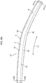
- the top plate 2 is elongated. As illustrated in Fig. 1A , the top plate 2 is curved along its length direction when viewed from the upper side of the top plate 2, namely, curved along arrow L1 in the drawings. As illustrated in Fig. 1B , the top plate 2 is also curved along its length direction when viewed from the side of a side-face of the top plate 2, namely, curved along arrow L2 in the drawings. Namely, in side view, the roof member 1 is curved along its length direction such that the top plate 2 is curved in a convex profile bowing toward the top plate 2 side.
- the two convex ridge line portions 3a, 3b are formed at both short direction ends of the top plate 2.
- the two vertical walls 4a, 4b face each other in a state extending from the respective convex ridge line portions 3a, 3b.
- the roof member 1 of the present exemplary embodiment is configured including the elongated top plate 2, the convex ridge line portions 3a, 3b at both short direction ends of the top plate 2, and the vertical walls 4a, 4b opposing each other in a state extending from the respective convex ridge line portions 3a, 3b.
- respective cross-sections taken perpendicularly to the length direction of the top plate 2 extend in a straight-line shape along the short direction at each length direction position.
- the top plate 2 of the present exemplary embodiment is viewed in respective perpendicular cross-sections along the length direction, as illustrated in Fig. 1C and Fig. 1D , the top plate 2 is flat at each length direction position.
- the convex ridge line portion 3a is a portion that connects the top plate 2 and the vertical wall 4a together, and is a curved portion when viewed in respective cross-sections taken perpendicularly to the length direction of the top plate 2.
- the two single-dotted dashed lines in the drawings respectively indicate the two ends of the convex ridge line portion 3a connected to the top plate 2 and the vertical wall 4a. Illustration of both ends of the convex ridge line portion 3b by single-dotted dashed lines is omitted from the drawings; however, the convex ridge line portion 3b is a portion that connects the top plate 2 and the vertical wall 4b together, and is a curved portion when viewed in respective cross-sections taken perpendicularly to the length direction of the top plate 2. As illustrated in Fig.
- the top plate 2 of the present exemplary embodiment includes a central portion at the short direction center of the top plate 2 where the Vickers hardness value of the top plate 2 is a minimum value, and maximum portions where the respective Vickers hardness value of the top plate 2 is a maximum value, namely, at a maximum value in each range out of a first range that is the range between the central portion and one short direction end of the top plate 2 and a second range that is the range between the center portion and another short direction end of the top plate 2.
- the central portion at the short direction center of the top plate 2 where the Vickers hardness value is the minimum value is called the minimum portion.
- the roof member 1 of the present exemplary embodiment is a member manufactured by pressing a blank BL, illustrated in Fig. 2B , using a manufacturing method of the roof member 1 of the present exemplary embodiment, described later.
- the Vickers hardness of the blank BL is, for example, 430 HV.
- the Vickers hardness of the minimum portion of the top plate 2 of the roof member 1 is, for example, approximately 417 HV, as illustrated in Fig. 14 .
- the Vickers hardness of the central portion of the top plate 2 is less than the Vickers hardness of the blank BL prior to being pressed.
- the Vickers hardness of an end portion of the flange 6b of the roof member 1 is, for example, 430 HV.
- the Vickers hardness of the central portion of the top plate 2 is less than the Vickers hardness of the end portion of the flange 6b.
- the top plate 2 is softer than the end portion of the flange 6b.
- the end portion of the flange 6b refers to a portion of the flange 6b of the roof member 1 from an end on the opposite side to the side connected to the concave ridge line portion 5b to up to 5 mm toward the ridge line portion 5b side. Note that as explained above, the reason the end portion of the flange 6b is harder than the top plate 2 is thought to be because the flange 6b is not deformed as much as the top plate 2 in the manufacturing method of the roof member 1, described later.
- the two concave ridge line portions 5a, 5b are respectively formed at end portions of the two vertical walls 4a, 4b on the opposite side to the side connected to the top plate 2.
- the two flanges 6a, 6b are connected to the two respective concave ridge line portions 5a, 5b. Illustration of the concave ridge line portion 5a is omitted from the drawings; however, the concave ridge line portion 5a is a portion that connects the vertical wall 4a and the flange 6a together, and is a curved portion when viewed in respective cross-sections taken perpendicularly to the length direction of the top plate 2.
- the concave ridge line portion 5b is a portion that connects the vertical wall 4b and the flange 6b together, and is a curved portion when viewed in respective cross-sections taken perpendicularly to the length direction of the top plate 2.
- the roof member 1 As illustrated in Fig. 1A , as viewed from the top plate 2 side in a state in which the top plate 2 is disposed so as to be orientated at a position on the upper side, the roof member 1 is curved from a front end portion 1a, namely one length direction end portion, to a rear end portion 1b, namely another length direction end portion. From another perspective, as illustrated in Fig. 1A and Fig. 1B , it may be said that the roof member 1 is integrally configured including a first section 8 including the front end portion 1 a, a third section 10 including the rear end portion 1b, and a second section 9 connecting the first section 8 and the third section 10 together.
- the radius of curvature R of the first section 8 is, for example, set to from 2000 mm to 9000 mm
- the radius of curvature R of the second section 9 is, for example, set to from 500 mm to 2000 mm
- the radius of curvature R of the third section 10 is, for example, set to from 2500 mm to 9000 mm.
- the radius of curvature R of the first section 8 is, for example, set to from 3000 mm to 15000 mm
- the radius of curvature R of the second section 9 is, for example, set to from 1000 mm at 15000 mm
- the radius of curvature R of the third section 10 is, for example, set to from 3000 mm at 15000 mm.
- the radius of curvature R of the first section 8 and the radius of curvature R of the third section 10 are each larger than the radius of curvature R of the second section 9.
- a step 11a having a step amount a2 (mm) is formed on the vertical wall 4a, so as to span the length direction of the vertical wall 4a at a portion thereof that is a distance of not less than 40% of the height h away from the plate thickness center of the top plate 2.
- a height from a plate thickness center of the end of curvature at a curvature start point on the top plate 2 side of the convex ridge line portion 3b, namely, from a plate thickness center of the top plate 2, up to an end of the vertical wall 4b on the concave ridge line portion 5b side, is a height h'.
- a step 11a' having a step amount a2' (mm) is formed on the vertical wall 4b, so as to span the length direction of the vertical wall 4b at a portion thereof that is a distance of not less than 40% of the height h away from the plate thickness center of the top plate 2.
- the cross-section profiles of the flanges 6a, 6b differ between the front end portion 1a and the rear end portion 1b in the length direction of the roof member 1.
- the angle of the flange 6b with respect to the vertical wall 4b is 30° at the front end portion 1a and 40° at the rear end portion 1b.
- the respective angles of the flanges 6a, 6b with respect to the vertical wall 4a change progressively along the length direction.
- the width of the short direction of the top plate 2 changes along the length direction so as become progressively wider from the front end portion 1a to the rear end portion 1b.
- the angle formed between the vertical wall 4b and the flange 6b at the first section 8 is preferably no less than the angle formed between the vertical wall 4b and the flange 6b at the third section 10.
- the foregoing explanation relates to configuration of the roof member 1 of the present exemplary embodiment.
- the press apparatus 17 of the present exemplary embodiment is used to manufacture the roof member 1 of the present exemplary embodiment.
- the press apparatus 17 is configured including a first press device 18 and a second press device 19.
- the press apparatus 17 of the present exemplary embodiment employs the first press device 18 to draw the blank BL illustrated in Fig. 2B so as to press the blank BL to form an intermediate formed component 30, illustrated in Fig. 3B , and then uses the second press device 19 to press the intermediate formed component 30 to manufacture a manufactured component, namely the roof member 1.
- the blank BL is configured by elongated high tensile sheet steel as a base material for manufacturing the roof member 1.
- the intermediate formed component 30 is a substantially hat-shaped member configured including the top plate 2, two convex ridge line portions 32a, 32b, two vertical walls 33a, 33b, two concave ridge line portions 34a, 34b, and two flanges 35a, 35b.
- pressing refers to a process of setting a forming target in a mold, closing the mold, and then opening the mold.
- the blank BL and the intermediate formed component 30 are examples of forming targets.
- a first mold 20 and a second mold 40 described later, are examples of molds.
- the first press device 18 is configured including the first mold 20 and a first moving device 25. As illustrated in Fig. 2B , the first mold 20 includes an upper mold 21, a lower mold 22, a first holder 23, and a second holder 24. The upper mold 21 is disposed at the upper side, and the lower mold 22 is disposed at the lower side. The first press device 18 is an example of a press device. The first mold 20 is an example of a mold. The upper mold 21 is an example of a die. The lower mold 22 is an example of a punch.
- the first press device 20 When forming the blank BL into the intermediate formed component 30, the first press device 20 has a function of, in a state in which the blank BL is in contact with the lower mold 22 at portions of the blank where the two convex ridge line portions 3a, 3b are to be formed, employing the upper mold 21 and the lower mold 22 to bend the blank BL into a profile protruding from the lower mold 22 side toward the upper mold 21 side, before sandwiching the portion of the blank BL where the top plate 2 is to be formed between the upper mold 21 and the lower mold 22 and indenting the portion of the blank BL where the top plate 2 is to be formed from the upper mold 21 side toward the lower mold 22 side, such that the portion of the blank BL where the top plate 2 is to be formed has a radius of curvature R (mm) that satisfies the following Equation (1).
- R radius of curvature
- the portions of the blank BL where the two convex ridge line portions 3a, 3b are to be formed are an example of a first portion. Further, the portion of the blank BL where the top plate 2 is to be formed is an example of a second portion.
- the first press device 18 is configured so as to sandwich the second portion between the upper mold 21 and the lower mold 22 and to indent the second portion from the upper mold 21 side toward the lower mold 22 side such that a portion of the second portion contacting the lower mold 22 satisfies the radius of curvature R (mm) in Equation (1).
- Equation (1) ⁇ s and ⁇ m are found by performing forming analysis of conditions to achieve a flat top plate 2.
- the radius of curvature R (mm) in Equation (1) is from 38 mm 1300 mm. Moreover, for a high tensile sheet steel blank having 1310 MPa grade tensile strength, the radius of curvature R (mm) in Equation (1) is from 32 mm 1020 mm. Moreover, for a high tensile sheet steel blank having 1470 MPa grade tensile strength, the radius of curvature R (mm) in Equation (1) is from 30 mm 725 mm.
- the first press device 20 has a function to sandwich the portion of the blank BL that will form the top plate 2 between the upper mold 21 and the lower mold 2 and to indent the portion of the blank BL that will form the top plate 2 from the upper mold 21 side toward the lower mold 22 side such that the radius of curvature R (mm) of the portion of the blank BL that will form the top plate 2 is within a range of from 38 mm to 725 mm.
- the upper mold 21 and the lower mold 22 are each elongated.
- An apex face of the lower mold 22 projects out and is curved along the length direction when the upper mold 21 and the lower mold 22 are viewed along the direction in which the upper mold 21 and the lower mold 22 face each other, and a groove that curves so as to follow the apex face of the lower mold 22 is formed in the upper mold 21, as illustrated in Fig. 2A and Fig. 2B .
- the apex face of the lower mold 22 is curved in a convex profile bowing toward the upper mold 21 side, and the groove that curves following the apex face of the lower mold 22 is formed in the upper mold 21, as illustrated in Fig. 2A and Fig. 2B .
- An apex face 22c of the lower mold 22 is configured by a recessed face having a radius of curvature R (mm) of from 38 mm to 725 mm.
- the groove-bottom of the groove of the upper mold 21 projects out with a radius of curvature R (mm) toward the lower mold 22 side, and a portion of the lower mold 22 opposing the bottom of the groove of the upper mold 21 (apex face) is recessed toward the upper mold 21 side with a radius of curvature R (mm) (see Fig. 2B ).
- the radius of curvature R (mm) of the present exemplary embodiment is, for example, 100 mm.
- each shoulder 22d corresponds to a portion of the lower mold 22 contacting the second portion of the blank BL.
- step portions 22a, 22a' are respectively formed at the two side faces of the lower mold 22, as illustrated in Fig. 2B . Further, step portions 21a, 21a' that follow the step portions 22a, 22a' are respectively formed to the two side faces of the groove in the upper mold 21.
- the first holder 23 and the second holder 24 are elongated following the upper mold 21 and the lower mold 22. As illustrated in Fig. 2B , the first holder 23 and the second holder 24 are respectively disposed at the two short direction sides of the lower mold 22. Further, the first holder 23 and the second holder 24 are biased toward the upper side by springs 26, 27.
- the first moving device 25 is configured so as to move the upper mold 21 toward the lower mold 22. Namely, the first moving device 25 is configured so as to move the upper mold 21 relative to the lower mold 22.
- the first moving device moves the upper mold 21 toward the lower mold 22 in a state in which the blank BL is disposed at a predetermined position in a gap between the upper mold 21 and the lower mold 22, as illustrated in Fig. 2B , the blank BL is pressed so as to form the intermediate formed component 30 in a state in which both short direction end sides of the blank BL are sandwiched between the respective first holder 23 and the second holder 24, and the upper mold 21.
- the first press device 18 is configured to curve the second portion of the blank BL in a convex profile bowing from the upper mold 21 side toward the lower mold 22 side such that the second portion has a radius of curvature R mm that satisfies Equation (1).
- the first press device 18 may curve the second portion of the blank BL in a convex profile bowing from the upper mold 21 side toward the lower mold 22 side such that the second portion has a radius of curvature R (mm) that satisfies Equation (2) instead of Equation (1).
- ⁇ TS is, for example, a shipment test value from the mill sheet listing obtained based on Tensile Testing for a JIS No. 5 sample.
- ⁇ YP is, for example, a shipment test value from the mill sheet listing obtained based on Tensile Testing for a JIS No. 5 sample.
- the inventors of the present application have made investigation pertaining to numerical value analysis of stress generated at the outer surface, namely an upper face, and at the inner surface, namely a back face, of the top plate 2 when forming the roof member 1 and roof members 1A, 1B, described later, with the plate thickness and material strength of the blank BL, the shape of the top plate 2, the pressing method, such as bending or drawing, and so on serving as the parameters. It was discovered from the results that when the roof members 1, 1A, and 1B are pressed without using a pad, deviatoric stress ⁇ that contributes to warping of the top plate 2 changes depending on the material strength of the blank BL and satisfies the following condition A.
- relationship B between the radius of curvature R (mm), the deviatoric stress ⁇ (MPa), the plate thickness (mm) of the blank BL, and the Young's Modulus (GPa) of the sheet steel configuring the blank BL satisfy the following relationship.
- Equation (2) is derived from condition A and relationship B above.
- Equation (2) ⁇ TS and ⁇ YP are found by performing forming analysis under the condition of forming a flat top plate 2.
- the second press device 19 is configured including the second mold 40 and a second moving device 45.
- the second mold 40 includes an upper mold 41, a lower mold 43, and a holder 43.
- the upper mold 41 is disposed at the upper side
- the lower mold 42 is disposed at the lower side.
- the upper mold 41 is moved toward the lower mold 43 side by the second moving device so as to change the angles of the two flanges 35a, 35b of the intermediate formed component 30.
- step portions 43a are respectively formed at the two side faces of the lower mold 43, as illustrated in Fig. 3B . Further, step portions 41a following the respective step portions 43 a are formed at the two side faces of the groove of the upper mold 41.
- the manufacturing method of the roof member 1 of the present exemplary embodiment is performed using the press apparatus 17. Further, the manufacturing method of the roof member 1 of the present exemplary embodiment includes a first pressing process, this being a process performed by the first press device 18, and a second pressing process, this being a process performed by the second press device 19.
- the blank BL is disposed at the predetermined position in the gap between the upper mold 21 and the lower mold 22, namely, the blank BL is set in the mold 40 at a predetermined position.
- an operator operates the first press device 18 such that the upper mold 21 is moved toward the lower mold 22 side by the first moving device 25, and the blank BL is drawn so as to press the blank BL.
- the first press device 18 bends the blank BL into a profile protruding from the lower mold 22 side toward the upper mold 21 side, as illustrated in Fig. 2B .
- the first press device 18 sandwiches the second portion of the blank BL between the upper mold 21 and the lower mold 22 and indents the second portion from the upper mold 21 side toward the lower mold 22 side. Namely, in the first pressing process, the upper mold 21 and the lower mold 22 are used to press the blank BL.
- the intermediate formed component 30 is formed from the blank BL as a result.
- the mold 40 employed in the first pressing process is manufactured according to the parameters of the blank BL so as to satisfy the conditions of Equation (1) or Equation (2).
- the first pressing process is performed using an upper mold 21 and lower mold 22, namely the mold 40, manufactured according to the plate thickness t of the blank BL and the Young's modulus E of the sheet steel configuring the blank BL so as to satisfy Equation (1) or Equation (2).
- plural molds 40 having different shapes to each other are prepared, and the first pressing process is performed after selecting the mold 40 according to the plate thickness t of the blank BL and the Young's Modulus E of the sheet steel configuring the blank BL so as to satisfy Equation (1) or Equation (2), and attaching the selected mold 40 to the body of the first press device 18.
- steps 36a, 36a' having a step amount a1 (mm) as defined by the following Equation (3) and Equation (4) are respectively formed on the two vertical walls 33a, 33b of the intermediate formed component 30, at portions thereof at a distance of not less than 40% of the height h, h' away from the top plate 2.
- the reference sign a1 indicates the step amount (mm) of the intermediate formed component 30
- the reference sign a2 indicates the step amount (mm) of the roof member 1
- the reference sign W indicates the short direction width (mm) of the top plate 2 of the roof member 1.
- the vertical wall 33a and the flange 35a are formed such that an angle DI1 formed between the vertical wall 33a and the flange 35a of the intermediate formed component 30 satisfies the following Equation (5).
- Equation (5) 1.0 ⁇ DI 2 ⁇ DI 1 ⁇ 1.2 ⁇ DI 2
- the reference sign DI1 indicates the angle formed between the vertical wall 33a and the flange 35a of the intermediate formed component 30, and the reference sign DI2 indicates the angle formed between the vertical wall 4a and the flange 6a of the roof member 1.
- the vertical wall 33b and the flange 35b of the intermediate formed component 30 are formed so as to satisfy the following Equation (6). 0.9 ⁇ DOF 1 / DOR 1 ⁇ 1
- DOF1 is the angle formed between the flange 35b and the vertical wall 33b including one end portion of the intermediate formed component 30
- DOR1 is the angle formed between the flange 35b and the vertical wall 33b including another end portion of the intermediate formed component 30.
- an end of the material of the blank BL flows in and the blank BL is flexed so as to form the flange 35b at the outside of the intermediate formed component 30.
- the intermediate formed component 30 is then removed from the first mold 20, thereby completing the first pressing process.
- the second portion of the blank BL is indented from the upper mold 21 side toward the lower mold 22 side such that the radius of curvature R (mm) of the second portion satisfies Equation (1) or Equation (2).
- the cross-section of the intermediate formed component 30 in the length direction of the top plate 2 adopts a deformed state that is flatter than when the mold was closed, namely, a state in which the radius of curvature has become larger.
- the intermediate formed component 30 is fitted onto the lower mold 43 of the second mold 40 of the second press device 19. Then, when an operator operates the second press device 19, the upper mold 41 is moved toward the lower mold 43 side by the second moving device, and the angles of the two flanges 35a, 35B of the intermediate formed component 30 are changed.
- the roof member 1 is thus manufactured from the intermediate formed component 30.
- the intermediate formed component 30 is pressed such that the step amounts of the vertical walls 33a, 33b of the intermediate formed component 30 become a2. Further, in the second pressing process, as illustrated in Fig. 7A , Fig. 7B , Fig. 7C , and Fig.
- the intermediate formed component 30 is sandwiched between the upper mold 41 and the lower mold 43 and the intermediate formed component 30 is then pressed such that the vertical wall 33a and the flange 35a of the intermediate formed component 30 form the vertical wall 4a and the flange 6a of the roof member 1.
- the intermediate formed component 30 is sandwiched between the upper mold 41 and the lower mold 43, and between the upper mold 41 and the holder 43, and the intermediate formed component 30 is then pressed such that the vertical wall 33b and the flange 35b of the intermediate formed component 30 form the vertical wall 4b and the flange 6b of the roof member 1.
- first portion prior contacting advantageous effect An advantageous effect of causing prior contact of the lower mold 22 against the first portion of the blank BL (referred to below as first portion prior contacting advantageous effect), is an advantageous effect in which, as illustrated in Fig. 2B , the blank BL is bent into a profile protruding from the lower mold 22 side toward the upper mold 21 side in a state in which the end portions 22d of the lower mold 22 are caused to contact the first portion of the blank BL, prior to then sandwiching the blank BL between the upper mold 21 and the lower mold 22 and indenting the blank BL from the upper mold 21 side toward the lower mold 22 side.
- this is an advantageous effect to form the first portion of the blank BL before the second portion.
- the second portion of the blank BL is formed prior to the first portion.
- compressive stress arises in the top plate 2 during mold closure in the first pressing process as a result of surplus material that arises when indenting the blank BL.
- spring-back occurs in the intermediate formed component 30 after the mold is opened in the first pressing process.
- the blank BL is bent into a profile protruding from the lower mold 22 side toward the upper mold 21 side in a state in which the end portions 22d of the lower mold 22 are caused to contact the first portion of the blank BL, prior to then sandwiching the blank BL between the upper mold 21 and the lower mold 22 and indenting the blank BL from the upper mold 21 side toward the lower mold 22 side.
- the first portion is formed before the second portion, thereby enabling a reduction in surplus material when indenting the blank BL compared to in the case of the first comparative embodiment. Accordingly, in the case of the present exemplary embodiment, compressive stress that arises in the top plate 2 during mold closure in the first pressing process can be reduced compared to in the case of the first comparative embodiment.
- the manufacturing method of the roof member 1 of the present exemplary embodiment thereby enables the roof member 1 to be manufactured such that closing in of the vertical walls 4a, 4b due to spring-back is suppressed compared to in the first comparative embodiment.
- An advantageous effect of performing the first pressing so as to obtain a radius of curvature R satisfying Equation (1) is an advantageous effect in which the second portion is indented from the upper mold 21 side toward the lower mold 22 side in the first pressing process such that the portion of the blank BL that will form the top plate 2 attains a radius of curvature R (mm) satisfying Equation (1), in other words, attains a radius of curvature satisfying Equation (2), or in yet other words, such that the radius of curvature R (mm) of the second portion of the blank BL is within a range of from 38 mm to 725 mm.
- the bottom of the groove in the upper mold 21 of the first press device 18 is flat in cross-section viewed along its length direction, and a portion of a lower mold 22 opposing the bottom of the groove of the upper mold 21 is flat in cross-section viewed along its length direction.
- step portions 21a are not formed to the upper mold 21, and step portions 22a are not formed to the lower mold 22.
- the second comparative embodiment is similar to the present exemplary embodiment with the exception of the points described above.
- twisting occurs in the top plate 2 due to residual deviatoric stress in the top plate 2 when the intermediate formed component 30 is formed in the first pressing process.
- a roof member 1 manufactured by a manufacturing method of the roof member 1 of the second comparative embodiment adopts a twisted state, as indicated by Comparative Examples 2 to 6 in the table in Fig. 15 .
- This result is thought to be due to the vertical walls 33a, 33b closing in due to spring-back after the first pressing, namely, after the mold is opened. Note that in the case of the second comparative embodiment, it is thought that the closing in of the vertical walls 33a, 33b due to spring-back after the first pressing occurs via the following mechanism.
- the intermediate formed component 30 is formed by deforming the second portion of the blank BL into a profile protruding toward the upper side by the time that the mold is closed.
- the second portion of the blank BL is formed by being bent into a profile protruding toward the upper side.
- the top plate 2 of the intermediate formed component 30 of the second comparative embodiment is bent into a profile protruding toward an outer surface side configuring the outer side in cross-section view.
- the intermediate formed component 30 is curved along its length direction, such that differences in stress can occur between the two short direction end sides of the top plate 2, at respective positions perpendicular to the length direction of the top plate 2.
- the roof member 1 manufactured according to the manufacturing method of the roof member 1 of the second comparative embodiment adopts a twisted state.
- the second portion is indented from the upper mold 21 side toward the lower mold 22 side in the first pressing process such that the portion of the blank BL that will form the top plate 2 attains a radius of curvature R (mm) that satisfies Equation (1), in other words, a radius of curvature that satisfies Equation (2), or in yet other words, such that the radius of curvature R (mm) of the second portion of the blank BL is within a range of from 38 mm to 725 mm.
- the blank BL is deformed into a profile protruding toward the upper side accompanying mold closure, and next, the portion of the blank BL that will form the top plate 2 is deformed to achieve a profile of the top plate 2 curving toward the lower side during mold closure.
- the mold is then opened, thereby forming the intermediate formed component 30.
- the top plate 2 of the intermediate formed component 30 of the present exemplary embodiment bears load from the upper side toward the lower side, thereby attaining a state in which the Bauschinger effect acts.
- twisting is less liable to arise in the top plate 2 of the intermediate formed component 30 formed by the first pressing process of the present exemplary embodiment than in the case of the second comparative embodiment.
- This result is thought to be due to the fact that the amount by which the vertical walls 33a, 33b close in due to spring-back after the first pressing process is less than that in the case of the second comparative embodiment.
- the second pressing process is performed after the first pressing process, the top plate 2 of the intermediate formed component 30 undergoes hardly any deformation in the second pressing process even when pressed.
- the top plate 2 of the intermediate formed component 30 has a (substantially) flat shape in cross-section view along its length direction due to forming the intermediate formed component 30 based on Equation (1) computed on the relationship between t, ⁇ s , ⁇ m , and E serving as the parameters for the top plate 2, or based on Equation (2) computed on the relationship between t, ⁇ TS , ⁇ YP , and E serving as the parameters for the top plate 2.
- Equation (1) computed on the relationship between t, ⁇ s , ⁇ m , and E serving as the parameters for the top plate 2
- Equation (2) computed on the relationship between t, ⁇ TS , ⁇ YP , and E serving as the parameters for the top plate 2.
- the intermediate formed component 30 is completed only after the second portion of the blank BL has been indented from the upper mold 21 side toward the lower mold 22 side. Accordingly, at respective positions perpendicular to the length direction of the top plate 2, the convex ridge line portions 32a, 32b at the two short direction ends of the top plate 2 can be formed with angles that are more acute than in the case of the second comparative embodiment. As a result, in the case of the present exemplary embodiment, spring-back that attempts to open out the vertical walls 33a, 33b is canceled out more easily than in the case of the second comparative embodiment.
- the roof member 1 in the present exemplary embodiment is less liable to twist due to the intermediate formed component 30 curving along its length direction compared to the roof member 1 of the second comparative embodiment, regardless of the fact that differences arise between the stresses at the two short direction end sides of the top plate 2, at the respective positions perpendicular to the length direction of the top plate 2.
- the manufacturing method of the roof member 1 of the present exemplary embodiment enables a roof member 1 to be manufactured that suppresses closing in of the vertical walls 4a, 4b due to spring-back more effectively than in the second comparative embodiment, namely, compared to cases in which the portion of the blank BL that will form the top plate 2 is pressed flat during mold closure in the first pressing process.
- the manufacturing method of the roof member 1 of the present exemplary embodiment enables a roof member 1 to be manufactured that suppresses twisting of the top plate 2 more effectively than in the second comparative embodiment, namely, compared to cases in which the portion of the blank BL that will form the top plate 2 is pressed flat during mold closure in the first pressing process. Further, as illustrated by the graph in Fig.
- twisting of the top plate 2 of a roof member 1 manufactured by the manufacturing method of the roof member 1 of the present exemplary embodiment is smaller than in a roof member 1 manufactured by the manufacturing method of the roof member 1 of the second comparative embodiment.
- the first press device 18, or the press apparatus 17 of the present exemplary embodiment enables a roof member 1 to be manufactured in which closing in of the vertical walls 4a, 4b due to spring-back is more effectively suppressed than in the case of the second comparative embodiment.
- the first press device 18, or the press apparatus 17 of the present exemplary embodiment enables a roof member 1 to be manufactured in which twisting of the top plate 2 is more effectively suppressed from occurring than in the case of the second comparative embodiment.
- the present exemplary embodiment exhibits the advantageous effect of being in accordance with Equation (1) in cases in which a blank BL configured by a high tensile sheet steel is pressed. Further, the advantageous effect of being accordance with Equation (1) is exhibited even in cases in which the top plate 2 is curved along its length direction when viewing the top plate 2 from the upper side, as in the case of the roof member 1 of the present exemplary embodiment. Moreover, the advantageous effect of being in accordance with Equation (1) is exhibited even in cases in which the roof member 1 is curved in a convex profile bowing toward the top plate 2 side when viewing the top plate 2 along the short direction, as in the case of the roof member 1 of the present exemplary embodiment.
- the steps 36a, 36a' are formed to the vertical walls 33a, 33b, and in the second pressing process, the step amount a1 of the steps 36a, 36a', namely the offset amount, is changed.
- the residual stress is reduced in each of the vertical walls 4a, 4b, such that residual deviatoric stress in the vertical walls 4a, 4b is also reduced.
- the vertical wall 33b and the flange 35b of the intermediate formed component 30 are formed in the first pressing process such that the angle therebetween satisfies Equation (6).
- twisting in the top plate 2 is reduced as a result of residual compressive stress being reduced in the flange 35b of the roof member 1.
- the intermediate formed component 30 is pressed in the second pressing process such that the vertical wall 33b and the flange 35b form the vertical wall 4b and the flange 6b of the roof member 1.
- compressive stress is reduced due to the differences in line lengths of the vertical wall 33b and the flange 35b that arise accompanying changing the angle between the vertical wall 33b and the flange 35b.
- the flange 35b of the intermediate formed component 30 is formed in the first pressing process by causing a material end of the blank BL to flow in and flexing the blank BL.
- the amount of spring-back in the first pressing process is reduced due to residual compressive stress being reduced.
- roof member 1A is an example of a pressed component and a specific pressed component.
- the roof member 1A of the present exemplary embodiment is not provided with the flanges 6a, 6b of the first exemplary embodiment illustrated in Fig. 1A , Fig. 1B , Fig. 1C , and Fig. 1D .
- the roof member 1A of the present exemplary embodiment has the same configuration as the roof member 1 of the first exemplary embodiment with the exception of this point.
- the press apparatus 17A of the present exemplary embodiment is used to manufacture the roof member 1A of the present exemplary embodiment.
- a first press device 18A of the present exemplary embodiment is not provided with the holders 23, 24 illustrated in Fig. 2B .
- the first press device 18A is an example of a press device.
- the press apparatus 17A of the present exemplary embodiment has the same configuration as the press apparatus 17 of the first exemplary embodiment with the exception of this point.
- an intermediate formed component 30A has the same configuration as the intermediate formed component 30 of the first exemplary embodiment with the exception of the point that the two flanges 35a, 35b are not provided.
- the intermediate formed component 30A of the present exemplary embodiment is configured as a gutter shaped member.
- a manufacturing method of the roof member 1A of the present exemplary embodiment is performed employing the press apparatus 17A.
- a first pressing process is the same as that of the first exemplary embodiment, with the exception of the point that it is performed using the first press device 18A. Note that in the present exemplary embodiment, in the first pressing process, the blank BL is pressed by bending to form the intermediate formed component 30A illustrated in Fig. 10 .
- the present exemplary embodiment exhibits the following advantageous effects of the first exemplary embodiment: the advantageous effect of first portion prior contacting, the advantageous effect of being in accordance with Equation (1), and the Advantageous Effects 1, 2, and 3.
- the roof member 1B is an example of a pressed component and a specific pressed component.
- the roof member 1B of the present exemplary embodiment is not provided with the flanges 6a, 6b illustrated in Fig. 1A , Fig. 1B , Fig. 1C , and Fig. 1D .
- a length direction central portion of the roof member 1B of the present exemplary embodiment is not curved in the short direction as viewed from the upper side of the top plate 2.
- the roof member 1 of the present exemplary embodiment is not curved in a convex profile bowing toward the top plate 2 side as viewed along the short direction of the top plate 2.
- Configuration of the roof member 1B of the present exemplary embodiment is similar to that of the roof member 1 of the first exemplary embodiment with the exception of these points.
- the press apparatus of the present exemplary embodiment is used to manufacture the roof member 1B of the present exemplary embodiment.
- a first press device and a second press device, not illustrated in the drawings, of the present exemplary embodiment are, similarly to the respective first press device 18A and the second press device 19 of the second exemplary embodiment, not provided with the first holders 23, 24 illustrated in Fig. 2B .
- a groove in the upper mold 21 of the first press device of the present exemplary embodiment is formed in a straight line shape that does not curve as viewed along the direction in which the upper mold 21 and the lower mold 22 face each other, nor in the short direction of the upper mold 21 and the lower mold 22.
- the lower mold 22 projects out in a straight line shape along its length direction. Configuration of the press apparatus of the present exemplary embodiment is similar to that of the press apparatus 17A of the second exemplary embodiment with the exception of the points above.
- An intermediate formed component, not illustrated in the drawings, formed by a first pressing process of the present exemplary embodiment is configured similarly to the intermediate formed component 30A of the second exemplary embodiment with the exception of the point that the top plate 2 and the vertical walls 33a, 33b are not curved along the length direction.
- the intermediate formed component of the present exemplary embodiment is configured by a gutter shaped member.
- the manufacturing method of the roof member 1B of the present exemplary embodiment is the same as that of the second exemplary embodiment with the exception of the point that the press apparatus of the present exemplary embodiment is employed. Note that in the case of the present exemplary embodiment, a blank BL is pressed by bending to form the intermediate formed component in the first pressing process.
- the present exemplary embodiment exhibits the following advantageous effects of the first exemplary embodiment: the advantageous effect first portion prior contacting and the advantageous effect of the vertical walls 4a, 4b being suppressed from closing in due to spring-back, as explained by the advantageous effect of being in accordance with Equation (1), and the Other Advantageous Effects 1 and 2.
- twisting and bending were compared between a roof member 1 configuring Example 1, manufactured by the manufacturing method of the roof member of the first exemplary embodiment described above, and a roof member configuring Comparative Example 1, manufactured by the manufacturing method of the roof member of the second comparative embodiment described above. Further, in the first evaluation, the Vickers hardness of the top plate 2 and the convex ridge line portions 3a, 3b of the roof member 1 of Example 1 and of the roof member of Comparative Example 1 were measured and compared.
- the roof member 1 of Example 1 A high tensile sheet steel blank having a plate thickness of 1.2 mm and 1310 MPa grade tensile strength was employed as the blank BL.
- the radius of curvature R of the first section 8 was 3000 mm
- the radius of curvature R of the second section 9 was 800 mm
- the radius of curvature R of the third section 10 was 4000 mm as viewed from the upper side of the top plate 2.
- the radius of curvature R of the first section 8 was 4000 mm
- the radius of curvature R of the second section 9 was 2000 mm
- the radius of curvature R of the third section 10 was 10000 mm as viewed along the short direction of the top plate 2, namely, as viewed from the side of a side-face of the roof member 1.
- the bend outer surface stress ⁇ s of the blank BL was 1234 MPa and the average stress ⁇ m was 100 MPa.
- the Young's Modulus E of the blank BL was 208 GPa.
- the roof member of Comparative Example 1 was manufactured by the manufacturing method of the roof member of the second comparative embodiment employing a high tensile sheet steel blank having a plate thickness of 1.2 mm and 1310 MPa grade tensile strength as the blank BL, similarly to in Example 1. Note that the roof member of Comparative Example 1 was manufactured such that each portion of the respective first, second, and third portions would have the same radius of curvature R as in Example 1.
- a 3-dimension measuring device not illustrated in the drawings, was used to measure the shapes of the roof member 1 of Example 1 and the roof member of Comparative Example 1.
- a computer not illustrated in the drawings, was used to compare measured data SD for the roof member 1 of Example 1 and the roof member of Comparative Example 1 against design data DD. Specifically, as illustrated in Fig.
- the cross-sections of length direction central portions of the top plate 2 were aligned (best-fit), and an angle of the top plate 2 along the short direction at a front end (rear end) in the design data DD was taken as a reference, and the amount of change in the angle of the top plate 2 at the front end (rear end) of each measured data point with respect to this reference was evaluated as twisting. Further, as illustrated in Fig. 12 , the offset amount in the width direction of a center position 02 of a front end face (rear end face) of each measured data point with respect to a center position O1 of the front end face (rear end face) in the design data DD was taken as bending.
- the graph in Fig. 13 illustrates evaluation results for Example 1 and Comparative Example 1. From the graph in Fig. 13 , it is apparent that the top plate 2 underwent less twisting in Example 1 than in Comparative Example 1. Further, from the graph in Fig. 13 , it is apparent that the vertical walls 33a, 33b underwent less bending in Example 1 than in Comparative Example 1. According to the evaluation results above, Example 1 may be considered as exhibiting the advantageous effects explained in the first exemplary embodiment.
- the graph in Fig. 14 illustrates the results of measuring Vickers hardness of the top plate, measured in a range spanning from one end to another end in the short direction of the top plate 2 of Example 1, and the Vickers hardness of the top plate measured in a range spanning from one end to another end in the short direction of the top plate of Comparative Example 1.
- the top plate 2 of Example 1 has a Vickers hardness value that is smaller than that of the top plate of Comparative Example 1 throughout, namely, over the entirety of a region spanning from the one end to the other end in the short direction of the top plate 2.
- the value of the Vickers hardness is equal throughout, whereas in the case of the top plate 2 of Example 1, the value of the Vickers hardness differs as follows. Namely, in the case of the top plate 2 of Example 1, the top plate 2 includes the central portion where the Vickers hardness value is a minimum value at the short direction center of the top plate 2, namely, the minimum portion. The top plate 2 also includes the maximum portions where the respective Vickers hardness value is a maximum value in each range out of a first range that is the range between the central portion and the one short direction end of the top plate 2 and a second range that is the range between the center portion and the other short direction end of the top plate 2.
- the reason the Vickers hardness characteristics of the top plate 2 of Example 1 and the top plate of Comparative Example 1 differ from each other in this manner is due to the top plate 2 of Example 1 having the advantageous effect of being in accordance with Equation (1), namely, the advantageous effect as a result of the Bauschinger effect. Further, as in the evaluation results described above, the roof member 1 of Example 1 does not twist, namely, has a smaller spring-back amount than the roof member of Comparative Example 1. From another perspective, the roof member 1 of Example 1 may be said to be of a higher precision than the roof member that includes a top plate having a Vickers hardness value that is equal throughout.
- each maximum portion is to indicate that portions where the Vickers hardness is a maximum value within each range are not at the two short direction ends of the top plate 2.
- the Vickers hardness value of the central portion namely, the minimum portion of the top plate 2 of Example 1 is at least 2.3% smaller than the Vickers hardness values of the respective maximum portions.
- twisting at the front end and the rear end of the top plate 2 was evaluated for roof members 1 of Examples 2 to 8 produced by simulation based on the roof member manufacturing method of the first exemplary embodiment described above, and for roof members of Comparative Examples 2 to 6 produced by simulation based on the roof member manufacturing method of the second comparative embodiment described above.
- the table in Fig. 15 lists the simulation parameters and evaluation results for Examples 2 to 8 and Comparative Examples 2 to 6.
- plate thickness refers to the thickness of the blank BL that is employed in the simulation.
- Strength refers to the tensile strength of the blank BL that is used in the simulation.
- Shape of top plate portion refers to there being a curved cross-section profile on the first mold 20 used in the simulation. The curved cross-section profile in the shape of the top plate portion of the first mold 20 used in the simulation corresponds to the radius of curvature R in Equation (1) or Equation (2).
- Example 2 the evaluation of cross-section 2 twisting in Example 2 was -7.52°, with the "-" sign indicating twisting that is clockwise. Thus, it may be said that when comparing the absolute values of the angles, the top plate 2 underwent less twisting in the roof member of Example 2 than in the roof member of Comparative Example 2. Further, when comparing combinations having the same simulation parameters for plate thickness and strength (for example, Example 3 and Comparative Example 2, Example 4 and Comparative Example 4, etc.), it is apparent that the top plate 2 underwent less twisting in the respective Examples than in the respective Comparative Examples. According to the evaluation results above, Examples 2 to 8 satisfy the conditions in Equation (1) and Equation (2), and thus may be considered as exhibiting the advantageous effect of being in accordance with Equation (1) irrespective of the differences in tensile strength between the blanks BL.
- twisting at the front end and the rear end was compared between roof members 1A of Examples 9 to 14 produced by simulation based on the roof member manufacturing method of the second exemplary embodiment described above, and for roof members of Comparative Examples 7 to 11 produced by simulation based on the roof member manufacturing method explained below.
- the roof members of Comparative Examples 7 to 11 were not provided with the flanges 6a, 6b illustrated in Fig. 1A , Fig. 1B , Fig. 1C , and Fig. 1D , similarly to in Examples 9 to 15, namely similarly to the roof member 1A of the second exemplary embodiment.
- the roof members of Comparative Examples 7 to 11 were produced by simulation under the assumption of pressing by bending.
- the table in Fig. 16 lists the simulation parameters and evaluation results for Examples 9 to 14 and Comparative Examples 7 to 11.
- "Plate thickness”, “strength”, “ top plate portion profile” “evaluation of cross-section 1 twisting” and “evaluation of cross-section 2 twisting” in the table in Fig. 15 refer to the same things as in the case of the table in Fig. 15 .
- Example 9 and Comparative Example 7 had the same simulation parameters for both plate thickness and strength.
- the simulation results for evaluation of cross-section 1 twisting it is apparent that the top plate 2 underwent less twisting in the roof member of Example 9 than in the roof member of Comparative Example 7.
- the simulation results for evaluation of cross-section 2 twisting it is apparent that the top plate 2 underwent less twisting in the roof member of Example 9 than in the roof member of Comparative Example 7.
- each Example satisfies the condition in Equation (1), and thus may be considered as exhibiting the advantageous effect of being in accordance with Equation (1) irrespective of the differences in tensile strength between the blanks BL.
- the pressed component may be an automotive component other than a roof member as long as it is manufactured by pressing that satisfies the conditions in Equation (1) or Equation (2).
- the pressed component may also be a component other than an automotive component as long as it is manufactured by pressing that satisfies the conditions in Equation (1) or Equation (2).
- the steps 11a, 11a' are respectively formed to the vertical walls 4a, 4b.
- the pressed component may be configured without forming the steps 11a, 11a' to the vertical walls 4a, 4b, as long as the pressed component is manufactured by pressing that satisfies the conditions in Equation (1) or Equation (2).
- the roof members 1, 1A, and 1B of the respective exemplary embodiments are manufactured by bending a blank BL from the lower mold 22 side toward the upper mold 21 side in a state in which the end portions 22d of the lower mold 22 contact the first portion of the blank BL, before sandwiching the blank BL between the upper mold 21 and the lower mold 22 and indenting the blank BL from the upper mold 21 side toward the lower mold 22 side.
- the roof members 1, 1A, and 1B of the respective exemplary embodiments are manufactured by forming the first portion of the blank BL prior to forming the second portion.
- the pressed component may have a different shape to that of the roof members 1, 1A, and 1B of the present exemplary embodiment as long as the pressed component is manufactured such that the first portion of the blank BL is formed prior to the second portion of the blank BL.
- the pressed component may be configured with the shapes of the respective modified examples described above.
- the additional disclosure is "A manufacturing method for a pressed component, the manufacturing method comprising:
Landscapes
- Engineering & Computer Science (AREA)
- Mechanical Engineering (AREA)
- Shaping Metal By Deep-Drawing, Or The Like (AREA)
- Bending Of Plates, Rods, And Pipes (AREA)
- Body Structure For Vehicles (AREA)
Abstract

Description
- The present disclosure relates to a manufacturing method for a pressed component, a pressed component, a mold, and a press apparatus.
- Automotive bodies are assembled by superimposing edges of multiple formed panels, joining the formed panels together by spot welding to configure a box body, and joining structural members to required locations on the box body by spot welding. Examples of structural members employed at a side section of an automotive body (body side) include side sills joined to both sides of a floor panel, an A-pillar lower and an A-pillar upper provided standing upward from a front portion of the side sill, a roof rail joined to an upper end portion of the A-pillar upper, and a B-pillar joining the side sill and the roof rail together.
- Generally speaking, configuration elements (such as respective outer panels) of structural members including A-pillar lowers, A-pillar uppers, and roof rails often have a substantially hat-shaped lateral cross-section profile configured by a top plate extending in a length direction, two convex ridge line portions respectively connected to both sides of the top plate, two vertical walls respectively connected to the two convex ridge line portions, two concave ridge line portions respectively connected to the two vertical walls, and two flanges respectively connected to the two concave ridge line portions.
- The configuration elements described above have comparatively complex lateral cross-section profiles and are elongated. In order to suppress an increase in manufacturing costs, the above configuration elements are generally manufactured by cold pressing. Moreover, in order to both increase strength and achieve a reduction in vehicle body weight in the interests of improving fuel consumption, thickness reduction of the above structural members is being promoted through the use of, for example, high tensile sheet steel having a tensile strength of 440 MPa or greater.
- However, when a high tensile sheet steel blank is cold pressed in an attempt to manufacture configuration elements that curve along their length direction, such as roof rail outer panels (referred to below as "roof members"; roof members are automotive structural members), spring-back occurs during removal from the press mold, leading to concerns of twisting in the top plate. There are therefore issues with shape fixability, whereby roof members cannot be formed in a desired shape.
- For example, Japanese Patent Application Laid-Open (
JP-A) No. 2004-314123 Patent Document 1") describes an invention in which a pressed component having a uniform hat-shaped lateral cross-section along its length direction is applied with a step during manufacture in order to suppress opening-out, and thus improve the shape fixability. - Moreover, the specification of Japanese Patent No.
5382281 Patent Document 2") describes an invention in which, during the manufacture of a pressed component that includes a top plate, vertical walls, and flanges, and that curves along its length direction, flanges formed in a first process are bent back in a second process so as to reduce residual stress in the flanges, thereby improving the shape fixability. - According to the invention described in
Patent Document 1, when manufacturing pressed components having a shape that curves along the length direction, such as in configuration elements of configuration members such as A-pillar lowers, A-pillar uppers, or roof rails, spring-back occurs in the top plate after removal from the mold, such that the desired shape cannot be formed. - According to the invention described in
Patent Document 2, when manufacturing pressed components that curve along the length direction and height direction and that include a bent portion in the vicinity of the length direction center, residual stress arises in the flange, residual stress arises within the faces of the vertical walls and the top plate, and residual deviatoric stress arises within the faces of the vertical walls and the top plate. As a result, spring-back occurs in the top plate after removal of the press component manufactured according to the invention described inPatent Document 2 from the mold, such that the desired shape cannot be formed. - An object of the present disclosure is to provide a manufacturing method for a specific pressed component in which the vertical walls are suppressed from closing in due to spring-back. Note that in the present specification, a "specific pressed component" is a pressed component configured including an elongated top plate, ridge line portions at both short direction ends of the top plate, and vertical walls that face each other in a state extending from the ridge line portions.
- A manufacturing method for a pressed component of a first aspect according to the present disclosure is a manufacturing method for a specific pressed component. The manufacturing method includes employing a die and a punch to bend a blank into a profile protruding from the punch side toward the die side in a state in which a punch is caused to contact a first portion of the blank where the two end ridge line portions are to be formed, and to sandwich a second portion of the blank where the top plate is to be formed between the die and the punch, and indent the second portion from the die side toward the punch side.
- A manufacturing method for a pressed component of a second aspect according to the present disclosure is a manufacturing method for a specific pressed component, wherein a punch and a die are employed to bend a blank from the punch side toward the die side in a state in which the punch is caused to contact a first portion of the blank where the two end ridge line portions are to be formed, and to sandwich a second portion of the blank where the top plate is to be formed between the die and the punch and indenting the second portion from the die side toward the punch side such that the second portion has a radius of curvature R (mm) that satisfies Equation (1).

- t is a plate thickness (mm) of the blank;
- σs is a short direction bend outer surface stress (MPa) of the blank to form the top plate in the short direction;
- σm is an average stress in cross section of short direction (MPa) of the portion of the blank to form the top plate; and
- E is a Young's Modulus (GPa) of sheet steel configuring the blank.
- A manufacturing method for a pressed component of a third aspect according to the present disclosure is a manufacturing method for a specific pressed component, wherein a die and a punch are employed to bend a blank from the punch side toward the die side in a state in which the punch is caused to contact a first portion of the blank where the two end ridge line portions are to be formed, and to sandwich a second portion of the blank where the top plate is to be formed between the die and the punch and to indent the second portion from the die side toward the punch side such that the second portion has a radius of curvature R (mm) that satisfies Equation (2)

- t is a plate thickness (mm) of the blank;
- σTS is a tensile strength (MPa) of the blank;
- σYP is a yield stress (MPa) of the blank; and
- E is a Young's Modulus (GPa) of sheet steel configuring the blank.
- A manufacturing method for a pressed component of a fourth aspect according to the present disclosure is the manufacturing method for a specific pressed component of the first to the third aspect, wherein an apex face of the punch is curved as viewed along a direction in which the punch and the die face each other, and a groove that is curved so as to follow the apex face of the punch is formed in the die, and a pressed component is manufactured in which the top plate is curved as viewed along a plate thickness direction of the top plate.
- A manufacturing method for a pressed component of a fifth aspect according to the present disclosure is the manufacturing method for a specific pressed component of the first to the fourth aspect, wherein an apex face of the punch is curved in a convex profile bowing toward the die side as viewed along an orthogonal direction orthogonal to both a direction in which the punch and the die face each other and the length direction of the punch, and a groove that is curved so as to follow the apex face of the punch is formed in the die, and a pressed component is manufactured in which the top plate is curved as viewed along a short direction of the top plate.
- A pressed component according to the present disclosure is a specific pressed component, in which the top plate includes a minimum portion where the Vickers hardness value is a minimum value between one end and another end in a short direction of the top plate, and maximum portions where the Vickers hardness value is a maximum value in each range out of a first range between the minimum portion and the one end, and a second range between the minimum portion and the other end.
- A mold according to the present disclosure is a mold for manufacturing a pressed component configured including an elongated top plate, ridge line portions at both short direction ends of the top plate, and vertical walls that face each other in a state extending from the ridge line portions. The mold includes a punch and die. An apex face of the punch is a recessed face having a radius of curvature R (mm) of from 38 mm to 725 mm, and a blank is pressed between the punch and the die by sandwiching a portion of the blank where the top plate is to be formed between the die and the punch and indenting the portion of the blank from the die side toward the punch side.
- A press apparatus according to the present disclosure includes the mold according to the present disclosure, as described above, and a moving section that moves the punch relative to the die.
- A specific pressed component in which closing in of the vertical walls due to spring-back is suppressed can be manufactured by employing the manufacturing method for a pressed component according to the present disclosure.
- In the pressed component according to the present disclosure, the amount by which the vertical walls close in due to spring-back is small.
- A specific pressed component in which closing in of the vertical walls due to spring-back is suppressed can be manufactured by employing the mold according to the present disclosure.
- A specific pressed component in which closing in of the vertical walls due to spring-back is suppressed can be manufactured by employing the press device according to the present disclosure.
-
-
Fig. 1A is a top view illustrating a roof member (pressed component) of a first exemplary embodiment. -
Fig. 1B is a side view illustrating a roof member of the first exemplary embodiment. -
Fig. 1C is a cross-section taken along 1C-1C inFig. 1A . -
Fig. 1D is a cross-section taken along 1D-1D inFig. 1A . -
Fig. 2A is a perspective view of a mold of a first press device employed in a first pressing process of a manufacturing method of a roof member of the first exemplary embodiment. -
Fig. 2B is a vertical cross-section of a first press device employed in a first pressing process of a manufacturing method of a roof member of the first exemplary embodiment. -
Fig. 3A is a perspective view of a mold of a second press device employed in a second pressing process of a manufacturing method of a roof member of the first exemplary embodiment. -
Fig. 3B is a vertical cross-section of a second press device employed in a second pressing process of a manufacturing method of a roof member of the first exemplary embodiment. -
Fig. 4A is a cross-section of an intermediate formed component formed by a first pressing process of the first exemplary embodiment, taken along 1C-1C inFig. 1A . -
Fig. 4B is a cross-section of an intermediate formed component formed by a first pressing process of the first exemplary embodiment, taken along 1D-1D inFig. 1A . -
Fig. 4C is a cross-section of a roof member manufactured by undergoing a second pressing process of the first exemplary embodiment, taken along 1C-1C inFig. 1A . -
Fig. 4D is a cross-section of an intermediate formed component formed by undergoing a second pressing process of the first exemplary embodiment, taken along 1D-1D inFig. 1A . -
Fig. 5A is a cross-section of an intermediate formed component formed by a first pressing process of the first exemplary embodiment, and illustrates the cross-section taken along 1C-1C inFig. 1A in detail. -
Fig. 5B is a cross-section of an intermediate formed component formed by a first pressing process of the first exemplary embodiment, and illustrates the cross-section taken along 1D-1D inFig. 1A in detail. -
Fig. 5C is a cross-section of a roof member manufactured by undergoing a second pressing process of the first exemplary embodiment, and illustrates the cross-section taken along 1C-1C inFig. 1A in detail. -
Fig. 5D is a cross-section of a roof member manufactured by undergoing a second pressing process of the first exemplary embodiment, and illustrates the cross-section taken along 1D-1D inFig. 1A in detail. -
Fig. 6A is a cross-section of a length direction central portion of an intermediate formed component formed by a first pressing process of the first exemplary embodiment. -
Fig. 6B is a cross-section of a portion of an intermediate formed component formed by a first pressing process of the first exemplary embodiment that corresponds to a cross-section taken along 1C-1C inFig. 1A . -
Fig. 6C is a cross-section of a length direction central portion of a roof member manufactured by undergoing a second pressing process of the first exemplary embodiment. -
Fig. 6D is a cross-section of a roof member manufactured by undergoing a second pressing process of the first exemplary embodiment, taken along 1C-1C inFig. 1A . -
Fig. 7A is a cross-section taken along 1C-1C inFig. 1A of an intermediate formed component formed by a first pressing process of the first exemplary embodiment, and is a cross-section that illustrates angles formed between vertical walls and flanges in detail. -
Fig. 7B is a cross-section taken along 1D-1D inFig. 1A of an intermediate formed component formed by a first pressing process of the first exemplary embodiment, and is a cross-section that illustrates angles formed between vertical walls and flanges in detail. -
Fig. 7C is a cross-section taken along 1C-1C inFig. 1A of a roof member manufactured by undergoing a second pressing process of the first exemplary embodiment, and is a cross-section that illustrates angles formed between vertical walls and flanges in detail. -
Fig. 7D is a cross-section taken along 1D-1D inFig. 1A of a roof member manufactured by undergoing a second pressing process of the first exemplary embodiment, and is a cross-section that illustrates angles formed between vertical walls and flanges in detail. -
Fig. 8A is a top view illustrating a roof member of a second exemplary embodiment. -
Fig. 8B is a side view illustrating a roof member of the second exemplary embodiment. -
Fig. 8C is a cross-section taken along 8C-8C inFig. 8A . -
Fig. 8D is a cross-section taken along 8D-8D inFig. 8A . -
Fig. 9 is a vertical cross-section of a first press device employed in a first pressing process of a manufacturing method of a roof member of the second exemplary embodiment. -
Fig. 10 is a vertical cross-section of a second press device employed in a second pressing process of a manufacturing method of a roof member of the second exemplary embodiment. -
Fig. 11A is a top view illustrating a roof member of a third exemplary embodiment. -
Fig. 11B is a side view illustrating a roof member of the third exemplary embodiment. -
Fig. 11C is a cross-section taken along 11C-11C inFig. 11A . -
Fig. 11D is a cross-section taken along 11D-11D inFig. 11A . -
Fig. 12 is a diagram for explaining an evaluation method for twisting and bending. -
Fig. 13 is a graph illustrating results from measuring twisting and bending in a top plate of a roof member 1 (Example 1) manufactured by a roof member manufacturing method of the first exemplary embodiment, and a roof member (Comparative Example 1) manufactured by a roof member manufacturing method of a second comparative embodiment. -
Fig. 14 is a graph illustrating results from measuring the Vickers hardness of a top plate as measured in a range spanning from one short direction end to another short direction end of a top plate of Example 1, and the Vickers hardness of a top plate as measured in a range spanning from one short direction end to another short direction end of a top plate of Comparative Example 1. -
Fig. 15 is a table illustrating evaluation results based on simulation regarding twisting in top plates of roof members of respective Examples (Examples 2 to 8) of the first exemplary embodiment, and twisting in top plates of roof members of respective Comparative Examples (Comparative Examples 2 to 6) of the second comparative embodiment. -
Fig. 16 is a table illustrating evaluation results based on simulation regarding twisting in top plates of roof members of respective Examples (Examples 9 to 14) of the second exemplary embodiment, and twisting in top plates of roof members of respective Comparative Examples (Comparative Examples 7 to 11) of the second comparative embodiment. - Explanation follows regarding the three exemplary embodiments (a first, a second, and a third exemplary embodiment) as embodiments for implementing the present disclosure. This will be followed by explanation regarding Examples. Note that in the present specification, exemplary embodiments refer to embodiments for implementing the present disclosure.
- Explanation follows regarding the first exemplary embodiment. First, explanation follows regarding configuration of a roof member (see
Fig. 1A ,Fig. 1B ,Fig. 1C , andFig. 1D ) of the present exemplary embodiment. Next, explanation is given regarding configuration of a press apparatus 17 (seeFig. 2A ,Fig. 2B ,Fig. 3A , andFig. 3B ) of the present exemplary embodiment. This will be followed by explanation regarding a manufacturing method of the roof member of the present exemplary embodiment. This will then be followed by explanation regarding advantageous effects of the present exemplary embodiment. - First, explanation follows regarding configuration of the
roof member 1 of the present exemplary embodiment, with reference to the drawings. Note that theroof member 1 is an example of a pressed component and a specific pressed component. - As illustrated in
Fig. 1A ,Fig. 1B ,Fig. 1C , andFig. 1D , theroof member 1 is an elongated member and has a substantially hat-shaped cross-section profile integrally configured including atop plate 2, two convexridge line portions vertical walls ridge line portions flanges ridge line portions roof member 1 is, for example, configured by a component cold pressed from a high tensile steel stock sheet having 1310 MPa grade tensile strength. Namely, theroof member 1 of the present exemplary embodiment is, for example, configured by a component cold pressed from a high tensile steel stock sheet having a tensile strength of from 440 MPa to 1600 MPa. - As illustrated in
Fig. 1A andFig. 1B , thetop plate 2 is elongated. As illustrated inFig. 1A , thetop plate 2 is curved along its length direction when viewed from the upper side of thetop plate 2, namely, curved along arrow L1 in the drawings. As illustrated inFig. 1B , thetop plate 2 is also curved along its length direction when viewed from the side of a side-face of thetop plate 2, namely, curved along arrow L2 in the drawings. Namely, in side view, theroof member 1 is curved along its length direction such that thetop plate 2 is curved in a convex profile bowing toward thetop plate 2 side. - As illustrated in
Fig. 1A andFig. 1B , the two convexridge line portions top plate 2. The twovertical walls ridge line portions roof member 1 of the present exemplary embodiment is configured including the elongatedtop plate 2, the convexridge line portions top plate 2, and thevertical walls ridge line portions - In the present exemplary embodiment, for example, respective cross-sections taken perpendicularly to the length direction of the
top plate 2 extend in a straight-line shape along the short direction at each length direction position. Namely, when thetop plate 2 of the present exemplary embodiment is viewed in respective perpendicular cross-sections along the length direction, as illustrated inFig. 1C andFig. 1D , thetop plate 2 is flat at each length direction position. Note that as illustrated inFig. 1D , the convexridge line portion 3a is a portion that connects thetop plate 2 and thevertical wall 4a together, and is a curved portion when viewed in respective cross-sections taken perpendicularly to the length direction of thetop plate 2. The two single-dotted dashed lines in the drawings respectively indicate the two ends of the convexridge line portion 3a connected to thetop plate 2 and thevertical wall 4a. Illustration of both ends of the convexridge line portion 3b by single-dotted dashed lines is omitted from the drawings; however, the convexridge line portion 3b is a portion that connects thetop plate 2 and thevertical wall 4b together, and is a curved portion when viewed in respective cross-sections taken perpendicularly to the length direction of thetop plate 2. As illustrated inFig. 14 , thetop plate 2 of the present exemplary embodiment includes a central portion at the short direction center of thetop plate 2 where the Vickers hardness value of thetop plate 2 is a minimum value, and maximum portions where the respective Vickers hardness value of thetop plate 2 is a maximum value, namely, at a maximum value in each range out of a first range that is the range between the central portion and one short direction end of thetop plate 2 and a second range that is the range between the center portion and another short direction end of thetop plate 2. Note that in the present specification, the central portion at the short direction center of thetop plate 2 where the Vickers hardness value is the minimum value is called the minimum portion. - The
roof member 1 of the present exemplary embodiment is a member manufactured by pressing a blank BL, illustrated inFig. 2B , using a manufacturing method of theroof member 1 of the present exemplary embodiment, described later. Note that the Vickers hardness of the blank BL is, for example, 430 HV. By contrast, the Vickers hardness of the minimum portion of thetop plate 2 of theroof member 1 is, for example, approximately 417 HV, as illustrated inFig. 14 . Namely, the Vickers hardness of the central portion of thetop plate 2 is less than the Vickers hardness of the blank BL prior to being pressed. Further, the Vickers hardness of an end portion of theflange 6b of theroof member 1 is, for example, 430 HV. Namely, the Vickers hardness of the central portion of thetop plate 2 is less than the Vickers hardness of the end portion of theflange 6b. In other words, it may be said that in theroof member 1 of the present exemplary embodiment, thetop plate 2 is softer than the end portion of theflange 6b. The end portion of theflange 6b refers to a portion of theflange 6b of theroof member 1 from an end on the opposite side to the side connected to the concaveridge line portion 5b to up to 5 mm toward theridge line portion 5b side. Note that as explained above, the reason the end portion of theflange 6b is harder than thetop plate 2 is thought to be because theflange 6b is not deformed as much as thetop plate 2 in the manufacturing method of theroof member 1, described later. - Further, the two concave
ridge line portions vertical walls top plate 2. The twoflanges ridge line portions ridge line portion 5a is omitted from the drawings; however, the concaveridge line portion 5a is a portion that connects thevertical wall 4a and theflange 6a together, and is a curved portion when viewed in respective cross-sections taken perpendicularly to the length direction of thetop plate 2. Illustration of the two ends of the concaveridge line portion 5b by single-dotted dashed lines is omitted from the drawings; however, the concaveridge line portion 5b is a portion that connects thevertical wall 4b and theflange 6b together, and is a curved portion when viewed in respective cross-sections taken perpendicularly to the length direction of thetop plate 2. - As illustrated in
Fig. 1A , as viewed from thetop plate 2 side in a state in which thetop plate 2 is disposed so as to be orientated at a position on the upper side, theroof member 1 is curved from afront end portion 1a, namely one length direction end portion, to arear end portion 1b, namely another length direction end portion. From another perspective, as illustrated inFig. 1A andFig. 1B , it may be said that theroof member 1 is integrally configured including afirst section 8 including thefront end portion 1 a, athird section 10 including therear end portion 1b, and asecond section 9 connecting thefirst section 8 and thethird section 10 together. - Note that in the present exemplary embodiment, in top view (as viewed from the upper side of the top plate 2) the radius of curvature R of the
first section 8 is, for example, set to from 2000 mm to 9000 mm, the radius of curvature R of thesecond section 9 is, for example, set to from 500 mm to 2000 mm, and the radius of curvature R of thethird section 10 is, for example, set to from 2500 mm to 9000 mm. Moreover, as illustrated inFig. 1B , in the present exemplary embodiment, in side view (as viewed from a width direction side of the top plate 2) the radius of curvature R of thefirst section 8 is, for example, set to from 3000 mm to 15000 mm, the radius of curvature R of thesecond section 9 is, for example, set to from 1000 mm at 15000 mm, and the radius of curvature R of thethird section 10 is, for example, set to from 3000 mm at 15000 mm. As described above, the radius of curvature R of thefirst section 8 and the radius of curvature R of thethird section 10 are each larger than the radius of curvature R of thesecond section 9. - As illustrated in
Fig. 1D , a height from a plate thickness center at the end of curvature at a curvature start point on thetop plate 2 side of the convexridge line portion 3a, namely, from a plate thickness center of thetop plate 2, up to an end of thevertical wall 4a on the concaveridge line portion 5a side, is a height h. In this configuration, astep 11a having a step amount a2 (mm) is formed on thevertical wall 4a, so as to span the length direction of thevertical wall 4a at a portion thereof that is a distance of not less than 40% of the height h away from the plate thickness center of thetop plate 2. Further, as illustrated inFig. 1D , a height from a plate thickness center of the end of curvature at a curvature start point on thetop plate 2 side of the convexridge line portion 3b, namely, from a plate thickness center of thetop plate 2, up to an end of thevertical wall 4b on the concaveridge line portion 5b side, is a height h'. In this configuration, astep 11a' having a step amount a2' (mm) is formed on thevertical wall 4b, so as to span the length direction of thevertical wall 4b at a portion thereof that is a distance of not less than 40% of the height h away from the plate thickness center of thetop plate 2. - As illustrated in
Fig. 1C andFig. 1D , the cross-section profiles of theflanges front end portion 1a and therear end portion 1b in the length direction of theroof member 1. Specifically, the angle of theflange 6b with respect to thevertical wall 4b is 30° at thefront end portion rear end portion 1b. Further, the respective angles of theflanges vertical wall 4a change progressively along the length direction. Further, the width of the short direction of thetop plate 2 changes along the length direction so as become progressively wider from thefront end portion 1a to therear end portion 1b. Note that as illustrated inFig. 1A to Fig. 1D , the angle formed between thevertical wall 4b and theflange 6b at thefirst section 8 is preferably no less than the angle formed between thevertical wall 4b and theflange 6b at thethird section 10. - The foregoing explanation relates to configuration of the
roof member 1 of the present exemplary embodiment. - Next, explanation follows regarding the
press apparatus 17 of the present exemplary embodiment, with reference to the drawings. Thepress apparatus 17 of the present exemplary embodiment is used to manufacture theroof member 1 of the present exemplary embodiment. As illustrated inFig. 2A ,Fig. 2B ,Fig. 3A , andFig. 3B , thepress apparatus 17 is configured including afirst press device 18 and asecond press device 19. Thepress apparatus 17 of the present exemplary embodiment employs thefirst press device 18 to draw the blank BL illustrated inFig. 2B so as to press the blank BL to form an intermediate formedcomponent 30, illustrated inFig. 3B , and then uses thesecond press device 19 to press the intermediate formedcomponent 30 to manufacture a manufactured component, namely theroof member 1. Note that the blank BL is configured by elongated high tensile sheet steel as a base material for manufacturing theroof member 1. - Note that as illustrated in
Fig. 3B , the intermediate formedcomponent 30 is a substantially hat-shaped member configured including thetop plate 2, two convexridge line portions vertical walls ridge line portions flanges component 30 are examples of forming targets. Further, afirst mold 20 and asecond mold 40, described later, are examples of molds. - The
first press device 18 is configured including thefirst mold 20 and a first movingdevice 25. As illustrated inFig. 2B , thefirst mold 20 includes anupper mold 21, alower mold 22, afirst holder 23, and asecond holder 24. Theupper mold 21 is disposed at the upper side, and thelower mold 22 is disposed at the lower side. Thefirst press device 18 is an example of a press device. Thefirst mold 20 is an example of a mold. Theupper mold 21 is an example of a die. Thelower mold 22 is an example of a punch. When forming the blank BL into the intermediate formedcomponent 30, thefirst press device 20 has a function of, in a state in which the blank BL is in contact with thelower mold 22 at portions of the blank where the two convexridge line portions upper mold 21 and thelower mold 22 to bend the blank BL into a profile protruding from thelower mold 22 side toward theupper mold 21 side, before sandwiching the portion of the blank BL where thetop plate 2 is to be formed between theupper mold 21 and thelower mold 22 and indenting the portion of the blank BL where thetop plate 2 is to be formed from theupper mold 21 side toward thelower mold 22 side, such that the portion of the blank BL where thetop plate 2 is to be formed has a radius of curvature R (mm) that satisfies the following Equation (1). The portions of the blank BL where the two convexridge line portions top plate 2 is to be formed is an example of a second portion.
- t is a plate thickness (mm) of the blank BL;
- σs is a short direction bend outer surface stress (MPa) of the portion of the blank BL to form the top plate;
- σm is an average stress in cross section of short direction (MPa) of the portion of the blank BL to form the top plate; and
- E is a Young's Modulus (GPa) of sheet steel configuring the blank BL.
- Note that the
first press device 18 is configured so as to sandwich the second portion between theupper mold 21 and thelower mold 22 and to indent the second portion from theupper mold 21 side toward thelower mold 22 side such that a portion of the second portion contacting thelower mold 22 satisfies the radius of curvature R (mm) in Equation (1). - Further, of the parameters in Equation (1), σs and σm are found by performing forming analysis of conditions to achieve a flat
top plate 2. - For a high tensile sheet steel blank having 980 MPa grade tensile strength, the radius of curvature R (mm) in Equation (1) is from 38 mm 1300 mm. Moreover, for a high tensile sheet steel blank having 1310 MPa grade tensile strength, the radius of curvature R (mm) in Equation (1) is from 32 mm 1020 mm. Moreover, for a high tensile sheet steel blank having 1470 MPa grade tensile strength, the radius of curvature R (mm) in Equation (1) is from 30 mm 725 mm. Accordingly, when sandwiching the portion of the blank BL that will form the
top plate 2 between theupper mold 21 and thelower mold 22 and indenting this portion from theupper mold 21 side toward thelower mold 22 side such that the radius of curvature R (mm) of the portion of the blank BL that will form thetop plate 2 is within a range of from 38 mm to 725 mm, pressing that satisfies Equation (1) is performed on a high tensile sheet steel blank having at least a strength within a range of from 980 MPa grade to 1470 MPa grade. As described above, it may be said that when the blank BL is formed into the intermediate formedcomponent 30, thefirst press device 20 has a function to sandwich the portion of the blank BL that will form thetop plate 2 between theupper mold 21 and thelower mold 2 and to indent the portion of the blank BL that will form thetop plate 2 from theupper mold 21 side toward thelower mold 22 side such that the radius of curvature R (mm) of the portion of the blank BL that will form thetop plate 2 is within a range of from 38 mm to 725 mm. - As illustrated in
Fig. 2A , theupper mold 21 and thelower mold 22 are each elongated. An apex face of thelower mold 22 projects out and is curved along the length direction when theupper mold 21 and thelower mold 22 are viewed along the direction in which theupper mold 21 and thelower mold 22 face each other, and a groove that curves so as to follow the apex face of thelower mold 22 is formed in theupper mold 21, as illustrated inFig. 2A andFig. 2B . Further, when theupper mold 21 and thelower mold 22 are viewed along the short direction of theupper mold 21 and thelower mold 22, this being a direction orthogonal to the direction in which theupper mold 21 and thelower mold 22 face each other, the apex face of thelower mold 22 is curved in a convex profile bowing toward theupper mold 21 side, and the groove that curves following the apex face of thelower mold 22 is formed in theupper mold 21, as illustrated inFig. 2A andFig. 2B . Anapex face 22c of thelower mold 22 is configured by a recessed face having a radius of curvature R (mm) of from 38 mm to 725 mm. Moreover, as viewed along the length direction, the groove-bottom of the groove of theupper mold 21 projects out with a radius of curvature R (mm) toward thelower mold 22 side, and a portion of thelower mold 22 opposing the bottom of the groove of the upper mold 21 (apex face) is recessed toward theupper mold 21 side with a radius of curvature R (mm) (seeFig. 2B ). The radius of curvature R (mm) of the present exemplary embodiment is, for example, 100 mm. - Note that as illustrated in
Fig. 2A andFig. 2B , the two short direction ends of theapex face 22c of thelower mold 22 are referred to asshoulders 22d. When thefirst press device 20 forms the blank BL into the intermediate formedcomponent 30, eachshoulder 22d corresponds to a portion of thelower mold 22 contacting the second portion of the blank BL. - Further, when the
lower mold 22 is viewed along the length direction,step portions lower mold 22, as illustrated inFig. 2B . Further,step portions step portions upper mold 21. - The
first holder 23 and thesecond holder 24 are elongated following theupper mold 21 and thelower mold 22. As illustrated inFig. 2B , thefirst holder 23 and thesecond holder 24 are respectively disposed at the two short direction sides of thelower mold 22. Further, thefirst holder 23 and thesecond holder 24 are biased toward the upper side bysprings - The first moving
device 25 is configured so as to move theupper mold 21 toward thelower mold 22. Namely, the first movingdevice 25 is configured so as to move theupper mold 21 relative to thelower mold 22. When the first moving device moves theupper mold 21 toward thelower mold 22 in a state in which the blank BL is disposed at a predetermined position in a gap between theupper mold 21 and thelower mold 22, as illustrated inFig. 2B , the blank BL is pressed so as to form the intermediate formedcomponent 30 in a state in which both short direction end sides of the blank BL are sandwiched between the respectivefirst holder 23 and thesecond holder 24, and theupper mold 21. - In the above explanation, the
first press device 18 is configured to curve the second portion of the blank BL in a convex profile bowing from theupper mold 21 side toward thelower mold 22 side such that the second portion has a radius of curvature R mm that satisfies Equation (1). However, thefirst press device 18 may curve the second portion of the blank BL in a convex profile bowing from theupper mold 21 side toward thelower mold 22 side such that the second portion has a radius of curvature R (mm) that satisfies Equation (2) instead of Equation (1).
- t is a plate thickness (mm) of the blank;
- σTS is a tensile strength (MPa) of the blank;
- σYP is a yield stress (MPa) of the blank; and
- E is a Young's Modulus (GPa) of sheet steel configuring the blank.
- σTS is, for example, a shipment test value from the mill sheet listing obtained based on Tensile Testing for a JIS No. 5 sample. Further, σYP is, for example, a shipment test value from the mill sheet listing obtained based on Tensile Testing for a JIS No. 5 sample.
- The inventors of the present application have made investigation pertaining to numerical value analysis of stress generated at the outer surface, namely an upper face, and at the inner surface, namely a back face, of the
top plate 2 when forming theroof member 1 androof members top plate 2, the pressing method, such as bending or drawing, and so on serving as the parameters. It was discovered from the results that when theroof members top plate 2 changes depending on the material strength of the blank BL and satisfies the following condition A. - Further, based on the assumption that deformation of the
top plate 2 during pressing is elastic deformation, relationship B between the radius of curvature R (mm), the deviatoric stress σ (MPa), the plate thickness (mm) of the blank BL, and the Young's Modulus (GPa) of the sheet steel configuring the blank BL satisfy the following relationship.
- Equation (2) is derived from condition A and relationship B above.
- Note that of the parameters in Equation (2), σTS and σYP are found by performing forming analysis under the condition of forming a flat
top plate 2. - The
second press device 19 is configured including thesecond mold 40 and a second movingdevice 45. As illustrated inFig. 3B , thesecond mold 40 includes anupper mold 41, alower mold 43, and aholder 43. Theupper mold 41 is disposed at the upper side, and thelower mold 42 is disposed at the lower side. In thesecond press device 19, in a state in which the intermediate formedcomponent 30 has been fitted onto thelower mold 43, theupper mold 41 is moved toward thelower mold 43 side by the second moving device so as to change the angles of the twoflanges component 30. - Further, when viewing the
lower mold 43 along the short direction,step portions 43a are respectively formed at the two side faces of thelower mold 43, as illustrated inFig. 3B . Further,step portions 41a following therespective step portions 43 a are formed at the two side faces of the groove of theupper mold 41. - The foregoing was an explanation relating to configuration of the
press apparatus 17 of the present exemplary embodiment. - Explanation follows regarding a manufacturing method of the
roof member 1 of the present exemplary embodiment, with reference to the drawings. The manufacturing method of theroof member 1 of the present exemplary embodiment is performed using thepress apparatus 17. Further, the manufacturing method of theroof member 1 of the present exemplary embodiment includes a first pressing process, this being a process performed by thefirst press device 18, and a second pressing process, this being a process performed by thesecond press device 19. - In the first pressing process, the blank BL is disposed at the predetermined position in the gap between the
upper mold 21 and thelower mold 22, namely, the blank BL is set in themold 40 at a predetermined position. Next, an operator operates thefirst press device 18 such that theupper mold 21 is moved toward thelower mold 22 side by the first movingdevice 25, and the blank BL is drawn so as to press the blank BL. When this is performed, first, in a state in which the first portion of the blank BL is in contact with theshoulders 22d of thelower mold 22, thefirst press device 18 bends the blank BL into a profile protruding from thelower mold 22 side toward theupper mold 21 side, as illustrated inFig. 2B . Next, thefirst press device 18 sandwiches the second portion of the blank BL between theupper mold 21 and thelower mold 22 and indents the second portion from theupper mold 21 side toward thelower mold 22 side. Namely, in the first pressing process, theupper mold 21 and thelower mold 22 are used to press the blank BL. The intermediate formedcomponent 30 is formed from the blank BL as a result. - Note that the
mold 40 employed in the first pressing process is manufactured according to the parameters of the blank BL so as to satisfy the conditions of Equation (1) or Equation (2). For example, the first pressing process is performed using anupper mold 21 andlower mold 22, namely themold 40, manufactured according to the plate thickness t of the blank BL and the Young's modulus E of the sheet steel configuring the blank BL so as to satisfy Equation (1) or Equation (2). Further, for example,plural molds 40 having different shapes to each other are prepared, and the first pressing process is performed after selecting themold 40 according to the plate thickness t of the blank BL and the Young's Modulus E of the sheet steel configuring the blank BL so as to satisfy Equation (1) or Equation (2), and attaching the selectedmold 40 to the body of thefirst press device 18. - Further, in the first pressing process, as illustrated in
Fig. 5A ,Fig. 5B ,Fig. 6A , andFig. 6B , steps 36a, 36a' having a step amount a1 (mm) as defined by the following Equation (3) and Equation (4) are respectively formed on the twovertical walls component 30, at portions thereof at a distance of not less than 40% of the height h, h' away from thetop plate 2.

- Note that the reference sign a1 indicates the step amount (mm) of the intermediate formed
component 30, the reference sign a2 indicates the step amount (mm) of theroof member 1, and the reference sign W indicates the short direction width (mm) of thetop plate 2 of theroof member 1. - Further, in the first pressing process, as illustrated in
Fig. 7A andFig. 7B , thevertical wall 33a and theflange 35a are formed such that an angle DI1 formed between thevertical wall 33a and theflange 35a of the intermediate formedcomponent 30 satisfies the following Equation (5).
- The reference sign DI1 indicates the angle formed between the
vertical wall 33a and theflange 35a of the intermediate formedcomponent 30, and the reference sign DI2 indicates the angle formed between thevertical wall 4a and theflange 6a of theroof member 1. - Further, in the first pressing process, the
vertical wall 33b and theflange 35b of the intermediate formedcomponent 30 are formed so as to satisfy the following Equation (6).
- Note that DOF1 is the angle formed between the
flange 35b and thevertical wall 33b including one end portion of the intermediate formedcomponent 30, and DOR1 is the angle formed between theflange 35b and thevertical wall 33b including another end portion of the intermediate formedcomponent 30. - Further, in the first pressing process, an end of the material of the blank BL flows in and the blank BL is flexed so as to form the
flange 35b at the outside of the intermediate formedcomponent 30. - The intermediate formed
component 30 is then removed from thefirst mold 20, thereby completing the first pressing process. - Note that as described above, when the intermediate formed
component 30 is formed by thefirst press device 18, the second portion of the blank BL is indented from theupper mold 21 side toward thelower mold 22 side such that the radius of curvature R (mm) of the second portion satisfies Equation (1) or Equation (2). When thefirst mold 20 is opened, as illustrated inFig. 4A andFig. 4B , the cross-section of the intermediate formedcomponent 30 in the length direction of thetop plate 2 adopts a deformed state that is flatter than when the mold was closed, namely, a state in which the radius of curvature has become larger. - Next, the intermediate formed
component 30 is fitted onto thelower mold 43 of thesecond mold 40 of thesecond press device 19. Then, when an operator operates thesecond press device 19, theupper mold 41 is moved toward thelower mold 43 side by the second moving device, and the angles of the twoflanges 35a, 35B of the intermediate formedcomponent 30 are changed. Theroof member 1 is thus manufactured from the intermediate formedcomponent 30. Note that in the second pressing process, the intermediate formedcomponent 30 is pressed such that the step amounts of thevertical walls component 30 become a2. Further, in the second pressing process, as illustrated inFig. 7A ,Fig. 7B ,Fig. 7C , andFig. 7D , the intermediate formedcomponent 30 is sandwiched between theupper mold 41 and thelower mold 43 and the intermediate formedcomponent 30 is then pressed such that thevertical wall 33a and theflange 35a of the intermediate formedcomponent 30 form thevertical wall 4a and theflange 6a of theroof member 1. Further, in the second pressing process, as illustrated inFig. 7A ,Fig. 7B ,Fig. 7C , andFig. 7D , the intermediate formedcomponent 30 is sandwiched between theupper mold 41 and thelower mold 43, and between theupper mold 41 and theholder 43, and the intermediate formedcomponent 30 is then pressed such that thevertical wall 33b and theflange 35b of the intermediate formedcomponent 30 form thevertical wall 4b and theflange 6b of theroof member 1. - The foregoing was an explanation relating to the manufacturing method of the
roof member 1 of the present exemplary embodiment. - Next, explanation follows regarding advantageous effects of the present exemplary embodiment, with reference to the drawings.
- Advantageous Effect of Causing Prior Contact of
Lower Mold 22 against First Portion of Blank BL - An advantageous effect of causing prior contact of the
lower mold 22 against the first portion of the blank BL (referred to below as first portion prior contacting advantageous effect), is an advantageous effect in which, as illustrated inFig. 2B , the blank BL is bent into a profile protruding from thelower mold 22 side toward theupper mold 21 side in a state in which theend portions 22d of thelower mold 22 are caused to contact the first portion of the blank BL, prior to then sandwiching the blank BL between theupper mold 21 and thelower mold 22 and indenting the blank BL from theupper mold 21 side toward thelower mold 22 side. In other words, this is an advantageous effect to form the first portion of the blank BL before the second portion. Explanation follows regarding the first portion prior contacting advantageous effect by comparing the present exemplary embodiment to a first comparative embodiment described below. Note that in the first comparative embodiment, where components and the like employed in the present exemplary embodiment are also employed, the same names and the like are used for such components, even if they are not illustrated in the drawings. - In the case of the first comparative embodiment, the second portion of the blank BL is formed prior to the first portion. Thus, in the case of the first comparative embodiment, compressive stress arises in the
top plate 2 during mold closure in the first pressing process as a result of surplus material that arises when indenting the blank BL. As a result, in the case of the first comparative embodiment, spring-back occurs in the intermediate formedcomponent 30 after the mold is opened in the first pressing process. - By contrast, in the case of the present exemplary embodiment, as illustrated in
Fig. 2A , the blank BL is bent into a profile protruding from thelower mold 22 side toward theupper mold 21 side in a state in which theend portions 22d of thelower mold 22 are caused to contact the first portion of the blank BL, prior to then sandwiching the blank BL between theupper mold 21 and thelower mold 22 and indenting the blank BL from theupper mold 21 side toward thelower mold 22 side. Namely, in the case of the present exemplary embodiment, the first portion is formed before the second portion, thereby enabling a reduction in surplus material when indenting the blank BL compared to in the case of the first comparative embodiment. Accordingly, in the case of the present exemplary embodiment, compressive stress that arises in thetop plate 2 during mold closure in the first pressing process can be reduced compared to in the case of the first comparative embodiment. - The manufacturing method of the
roof member 1 of the present exemplary embodiment thereby enables theroof member 1 to be manufactured such that closing in of thevertical walls - An advantageous effect of performing the first pressing so as to obtain a radius of curvature R satisfying Equation (1) (referred to below as advantageous effect of accordance to Equation (1)) is an advantageous effect in which the second portion is indented from the
upper mold 21 side toward thelower mold 22 side in the first pressing process such that the portion of the blank BL that will form thetop plate 2 attains a radius of curvature R (mm) satisfying Equation (1), in other words, attains a radius of curvature satisfying Equation (2), or in yet other words, such that the radius of curvature R (mm) of the second portion of the blank BL is within a range of from 38 mm to 725 mm. Explanation follows regarding the advantageous effect of accordance to Equation (1) by comparing the present exemplary embodiment to a second comparative embodiment described below. Note that in the second comparative embodiment, where components and the like employed in the present exemplary embodiment are also employed, the same names and the like are used for such components, even if they are not illustrated in the drawings. - In the case of the second comparative embodiment, the bottom of the groove in the
upper mold 21 of thefirst press device 18 is flat in cross-section viewed along its length direction, and a portion of alower mold 22 opposing the bottom of the groove of theupper mold 21 is flat in cross-section viewed along its length direction. Further, in the case of the second comparative embodiment,step portions 21a are not formed to theupper mold 21, andstep portions 22a are not formed to thelower mold 22. The second comparative embodiment is similar to the present exemplary embodiment with the exception of the points described above. - In the case of the second comparative embodiment, twisting occurs in the
top plate 2 due to residual deviatoric stress in thetop plate 2 when the intermediate formedcomponent 30 is formed in the first pressing process. As a result, aroof member 1 manufactured by a manufacturing method of theroof member 1 of the second comparative embodiment adopts a twisted state, as indicated by Comparative Examples 2 to 6 in the table inFig. 15 . This result is thought to be due to thevertical walls vertical walls component 30 is formed by deforming the second portion of the blank BL into a profile protruding toward the upper side by the time that the mold is closed. Namely, in the gap between theupper mold 21 and thelower mold 22, the second portion of the blank BL is formed by being bent into a profile protruding toward the upper side. Thus, thetop plate 2 of the intermediate formedcomponent 30 of the second comparative embodiment is bent into a profile protruding toward an outer surface side configuring the outer side in cross-section view. As a result, stress attempting to cause thevertical walls top plate 2. Moreover, in the case of the second comparative embodiment, the intermediate formedcomponent 30 is curved along its length direction, such that differences in stress can occur between the two short direction end sides of thetop plate 2, at respective positions perpendicular to the length direction of thetop plate 2. As a result, theroof member 1 manufactured according to the manufacturing method of theroof member 1 of the second comparative embodiment adopts a twisted state. - By contrast, in the case of the present exemplary embodiment, the second portion is indented from the
upper mold 21 side toward thelower mold 22 side in the first pressing process such that the portion of the blank BL that will form thetop plate 2 attains a radius of curvature R (mm) that satisfies Equation (1), in other words, a radius of curvature that satisfies Equation (2), or in yet other words, such that the radius of curvature R (mm) of the second portion of the blank BL is within a range of from 38 mm to 725 mm. Thus, in the first pressing process of the present exemplary embodiment, the blank BL is deformed into a profile protruding toward the upper side accompanying mold closure, and next, the portion of the blank BL that will form thetop plate 2 is deformed to achieve a profile of thetop plate 2 curving toward the lower side during mold closure. The mold is then opened, thereby forming the intermediate formedcomponent 30. Namely, it is speculated that after being plastically deformed toward the upper side, thetop plate 2 of the intermediate formedcomponent 30 of the present exemplary embodiment bears load from the upper side toward the lower side, thereby attaining a state in which the Bauschinger effect acts. As a result, twisting is less liable to arise in thetop plate 2 of the intermediate formedcomponent 30 formed by the first pressing process of the present exemplary embodiment than in the case of the second comparative embodiment. This result is thought to be due to the fact that the amount by which thevertical walls top plate 2 of the intermediate formedcomponent 30 undergoes hardly any deformation in the second pressing process even when pressed. It is thought that as a result there is no twisting or any twisting amount is small in theroof member 1 manufactured according to the manufacturing method of theroof member 1 of the present exemplary embodiment, compared to in the case of the second comparative embodiment, as illustrated by the graph inFig. 13 , described later. Note that in the case of the present exemplary embodiment, thetop plate 2 of the intermediate formedcomponent 30 has a (substantially) flat shape in cross-section view along its length direction due to forming the intermediate formedcomponent 30 based on Equation (1) computed on the relationship between t, σs, σm, and E serving as the parameters for thetop plate 2, or based on Equation (2) computed on the relationship between t, σTS, σYP, and E serving as the parameters for thetop plate 2. This enables residual deviatoric stress to be suppressed from occurring at the press bottom dead center in the second pressing process performed after the first pressing process. Further, in the case of the present exemplary embodiment, in the first pressing process, the intermediate formedcomponent 30 is completed only after the second portion of the blank BL has been indented from theupper mold 21 side toward thelower mold 22 side. Accordingly, at respective positions perpendicular to the length direction of thetop plate 2, the convexridge line portions top plate 2 can be formed with angles that are more acute than in the case of the second comparative embodiment. As a result, in the case of the present exemplary embodiment, spring-back that attempts to open out thevertical walls roof member 1 in the present exemplary embodiment is less liable to twist due to the intermediate formedcomponent 30 curving along its length direction compared to theroof member 1 of the second comparative embodiment, regardless of the fact that differences arise between the stresses at the two short direction end sides of thetop plate 2, at the respective positions perpendicular to the length direction of thetop plate 2. - Thus, the manufacturing method of the
roof member 1 of the present exemplary embodiment enables aroof member 1 to be manufactured that suppresses closing in of thevertical walls top plate 2 is pressed flat during mold closure in the first pressing process. Thus, the manufacturing method of theroof member 1 of the present exemplary embodiment enables aroof member 1 to be manufactured that suppresses twisting of thetop plate 2 more effectively than in the second comparative embodiment, namely, compared to cases in which the portion of the blank BL that will form thetop plate 2 is pressed flat during mold closure in the first pressing process. Further, as illustrated by the graph inFig. 13 , twisting of thetop plate 2 of aroof member 1 manufactured by the manufacturing method of theroof member 1 of the present exemplary embodiment is smaller than in aroof member 1 manufactured by the manufacturing method of theroof member 1 of the second comparative embodiment. Further, using thefirst mold 20, thefirst press device 18, or thepress apparatus 17 of the present exemplary embodiment enables aroof member 1 to be manufactured in which closing in of thevertical walls first mold 20, thefirst press device 18, or thepress apparatus 17 of the present exemplary embodiment enables aroof member 1 to be manufactured in which twisting of thetop plate 2 is more effectively suppressed from occurring than in the case of the second comparative embodiment. - In particular, the present exemplary embodiment exhibits the advantageous effect of being in accordance with Equation (1) in cases in which a blank BL configured by a high tensile sheet steel is pressed. Further, the advantageous effect of being accordance with Equation (1) is exhibited even in cases in which the
top plate 2 is curved along its length direction when viewing thetop plate 2 from the upper side, as in the case of theroof member 1 of the present exemplary embodiment. Moreover, the advantageous effect of being in accordance with Equation (1) is exhibited even in cases in which theroof member 1 is curved in a convex profile bowing toward thetop plate 2 side when viewing thetop plate 2 along the short direction, as in the case of theroof member 1 of the present exemplary embodiment. - Explanation follows regarding other advantageous effects of the present exemplary embodiment.
- In the case of the present exemplary embodiment, in the first pressing process, the
steps vertical walls steps vertical walls vertical walls vertical walls roof member 1, namely, portions above thesteps steps top plate 2 and bending in thevertical walls Fig. 13 . Note that in the case of the present exemplary embodiment, stress is reduced throughout the entirety of thevertical walls steps vertical walls - Generally, when a non-illustrated pressed component is manufactured having a shape curved along its length direction as viewed from the upper side of a top plate, residual tensile stress is liable to occur in vertical walls and flanges at the inside of the curved portion. However, in the case of the present exemplary embodiment, the
vertical wall 33a and theflange 35a are formed in the first pressing process such that the angle DI1 formed between thevertical wall 33a and theflange 35a of the intermediate formedcomponent 30 satisfies Equation (5). Thus, in the present exemplary embodiment, twisting in thetop plate 2 is reduced as a result of residual tensile stress being reduced in thevertical wall 4a and theflange 6a of theroof member 1. Note that in the case of the present exemplary embodiment, residual stress at lower portions of thevertical walls steps vertical walls - Further, in the case of the present exemplary embodiment, the
vertical wall 33b and theflange 35b of the intermediate formedcomponent 30 are formed in the first pressing process such that the angle therebetween satisfies Equation (6). Thus, in the present exemplary embodiment, twisting in thetop plate 2 is reduced as a result of residual compressive stress being reduced in theflange 35b of theroof member 1. Note that in the case of the present exemplary embodiment, as illustrated in inFig. 7A ,Fig. 7B ,Fig. 7C , andFig. 7D , the intermediate formedcomponent 30 is pressed in the second pressing process such that thevertical wall 33b and theflange 35b form thevertical wall 4b and theflange 6b of theroof member 1. In such cases, compressive stress is reduced due to the differences in line lengths of thevertical wall 33b and theflange 35b that arise accompanying changing the angle between thevertical wall 33b and theflange 35b. - Further, in the case of the present exemplary embodiment, the
flange 35b of the intermediate formedcomponent 30 is formed in the first pressing process by causing a material end of the blank BL to flow in and flexing the blank BL. Thus, in the first pressing process of the present exemplary embodiment, the amount of spring-back in the first pressing process is reduced due to residual compressive stress being reduced. - The foregoing was an explanation relating to advantageous effects of the present exemplary embodiment.
- Next, explanation follows regarding the second exemplary embodiment. First, explanation follows regarding configuration of a
roof member 1A of the present exemplary embodiment illustrated inFig. 8A ,Fig. 8B ,Fig. 8C , andFig. 8D . Explanation then follows regarding configuration of a press apparatus 17A of the present exemplary embodiment illustrated inFig. 9 andFig. 10 . This will be followed by explanation regarding a manufacturing method of the roof member of the present exemplary embodiment. This will then be followed by explanation regarding advantageous effects of the present exemplary embodiment. Note that the following explanation describes portions of the present exemplary embodiment differing from those of the first exemplary embodiment. - First, explanation follows regarding configuration of the
roof member 1A of the present exemplary embodiment, with reference to the drawings. Note that theroof member 1A is an example of a pressed component and a specific pressed component. - As illustrated in
Fig. 8A ,Fig. 8B ,Fig. 8C , andFig. 8D , theroof member 1A of the present exemplary embodiment is not provided with theflanges Fig. 1A ,Fig. 1B ,Fig. 1C , andFig. 1D . Theroof member 1A of the present exemplary embodiment has the same configuration as theroof member 1 of the first exemplary embodiment with the exception of this point. - Explanation follows regarding the press apparatus 17A of the present exemplary embodiment, with reference to the drawings. The press apparatus 17A of the present exemplary embodiment is used to manufacture the
roof member 1A of the present exemplary embodiment. - A first press device 18A of the present exemplary embodiment, as illustrated in
Fig. 9 , is not provided with theholders Fig. 2B . Note that the first press device 18A is an example of a press device. The press apparatus 17A of the present exemplary embodiment has the same configuration as thepress apparatus 17 of the first exemplary embodiment with the exception of this point. Note that an intermediate formedcomponent 30A has the same configuration as the intermediate formedcomponent 30 of the first exemplary embodiment with the exception of the point that the twoflanges component 30A of the present exemplary embodiment is configured as a gutter shaped member. - Next, explanation follows regarding a manufacturing method of the
roof member 1A of the present exemplary embodiment. The manufacturing method of theroof member 1A of the present exemplary embodiment is performed employing the press apparatus 17A. Moreover, in the manufacturing method of theroof member 1A of the present exemplary embodiment, a first pressing process is the same as that of the first exemplary embodiment, with the exception of the point that it is performed using the first press device 18A. Note that in the present exemplary embodiment, in the first pressing process, the blank BL is pressed by bending to form the intermediate formedcomponent 30A illustrated inFig. 10 . - The present exemplary embodiment exhibits the following advantageous effects of the first exemplary embodiment: the advantageous effect of first portion prior contacting, the advantageous effect of being in accordance with Equation (1), and the
Advantageous Effects - The foregoing was an explanation relating to the second exemplary embodiment.
- Explanation follows regarding the third exemplary embodiment. First, explanation is given regarding configuration of a
roof member 1B of the present exemplary embodiment illustrated inFig. 11A ,Fig. 11B ,Fig. 11C , andFig. 11D . Next, explanation will be given regarding configuration of a press apparatus, not illustrated in the drawings, of the present exemplary embodiment. Then, explanation will be given regarding a manufacturing method of the roof member of the present exemplary embodiment. This will be followed by explanation regarding advantageous effects of the present exemplary embodiment. Note that in the following explanation, explanation will be given regarding portions of the present exemplary embodiment which differ from those of the first and second exemplary embodiments. In the explanation of the present exemplary embodiment, when the reference signs used for components and the like are similar to the reference signs used for components and the like in the first and second exemplary embodiments, similar reference signs are used in the explanation even if not illustrated in the drawings. - First, explanation follows regarding configuration of the
roof member 1B of the present exemplary embodiment, with reference to the drawings. Theroof member 1B is an example of a pressed component and a specific pressed component. - As illustrated in
Fig. 11A ,Fig. 11B ,Fig. 11C , andFig. 11D , theroof member 1B of the present exemplary embodiment is not provided with theflanges Fig. 1A ,Fig. 1B ,Fig. 1C , andFig. 1D . Further, a length direction central portion of theroof member 1B of the present exemplary embodiment is not curved in the short direction as viewed from the upper side of thetop plate 2. Moreover, theroof member 1 of the present exemplary embodiment is not curved in a convex profile bowing toward thetop plate 2 side as viewed along the short direction of thetop plate 2. Configuration of theroof member 1B of the present exemplary embodiment is similar to that of theroof member 1 of the first exemplary embodiment with the exception of these points. - Explanation follows regarding the press apparatus, not illustrated in the drawings, of the present exemplary embodiment. The press apparatus of the present exemplary embodiment is used to manufacture the
roof member 1B of the present exemplary embodiment. - A first press device and a second press device, not illustrated in the drawings, of the present exemplary embodiment are, similarly to the respective first press device 18A and the
second press device 19 of the second exemplary embodiment, not provided with thefirst holders Fig. 2B . Further, a groove in theupper mold 21 of the first press device of the present exemplary embodiment is formed in a straight line shape that does not curve as viewed along the direction in which theupper mold 21 and thelower mold 22 face each other, nor in the short direction of theupper mold 21 and thelower mold 22. Further, thelower mold 22 projects out in a straight line shape along its length direction. Configuration of the press apparatus of the present exemplary embodiment is similar to that of the press apparatus 17A of the second exemplary embodiment with the exception of the points above. An intermediate formed component, not illustrated in the drawings, formed by a first pressing process of the present exemplary embodiment is configured similarly to the intermediate formedcomponent 30A of the second exemplary embodiment with the exception of the point that thetop plate 2 and thevertical walls - Explanation follows regarding the manufacturing method of the
roof member 1B of the present exemplary embodiment. The manufacturing method of theroof member 1B of the present exemplary embodiment is the same as that of the second exemplary embodiment with the exception of the point that the press apparatus of the present exemplary embodiment is employed. Note that in the case of the present exemplary embodiment, a blank BL is pressed by bending to form the intermediate formed component in the first pressing process. - The present exemplary embodiment exhibits the following advantageous effects of the first exemplary embodiment: the advantageous effect first portion prior contacting and the advantageous effect of the
vertical walls Advantageous Effects - The foregoing was an explanation relating to the third exemplary embodiment.
- Explanation follows regarding first, second, and third evaluations in which Examples and Comparative Examples were evaluated, with reference to the drawings. Note that in the following explanation, when the reference signs used for components and the like are similar to the reference signs used for components and the like in the present exemplary embodiment and the second comparative embodiment, the reference signs for these components and the like are being carried over as-is.
- In the first evaluation, twisting and bending were compared between a
roof member 1 configuring Example 1, manufactured by the manufacturing method of the roof member of the first exemplary embodiment described above, and a roof member configuring Comparative Example 1, manufactured by the manufacturing method of the roof member of the second comparative embodiment described above. Further, in the first evaluation, the Vickers hardness of thetop plate 2 and the convexridge line portions roof member 1 of Example 1 and of the roof member of Comparative Example 1 were measured and compared. - First, explanation follows regarding the
roof member 1 of Example 1. A high tensile sheet steel blank having a plate thickness of 1.2 mm and 1310 MPa grade tensile strength was employed as the blank BL. In theroof member 1 of Example 1 manufactured by the manufacturing method of the roof member of the present exemplary embodiment, the radius of curvature R of thefirst section 8 was 3000 mm, the radius of curvature R of thesecond section 9 was 800 mm, and the radius of curvature R of thethird section 10 was 4000 mm as viewed from the upper side of thetop plate 2. Further, in theroof member 1 of Example 1, the radius of curvature R of thefirst section 8 was 4000 mm, the radius of curvature R of thesecond section 9 was 2000 mm, and the radius of curvature R of thethird section 10 was 10000 mm as viewed along the short direction of thetop plate 2, namely, as viewed from the side of a side-face of theroof member 1. Note that in the first pressing process, the bend outer surface stress σs of the blank BL was 1234 MPa and the average stress σm was 100 MPa. Further, the Young's Modulus E of the blank BL was 208 GPa. - The roof member of Comparative Example 1 was manufactured by the manufacturing method of the roof member of the second comparative embodiment employing a high tensile sheet steel blank having a plate thickness of 1.2 mm and 1310 MPa grade tensile strength as the blank BL, similarly to in Example 1. Note that the roof member of Comparative Example 1 was manufactured such that each portion of the respective first, second, and third portions would have the same radius of curvature R as in Example 1.
- In the comparison method of the present evaluation, first, a 3-dimension measuring device, not illustrated in the drawings, was used to measure the shapes of the
roof member 1 of Example 1 and the roof member of Comparative Example 1. Next, a computer, not illustrated in the drawings, was used to compare measured data SD for theroof member 1 of Example 1 and the roof member of Comparative Example 1 against design data DD. Specifically, as illustrated inFig. 12 , the cross-sections of length direction central portions of thetop plate 2 were aligned (best-fit), and an angle of thetop plate 2 along the short direction at a front end (rear end) in the design data DD was taken as a reference, and the amount of change in the angle of thetop plate 2 at the front end (rear end) of each measured data point with respect to this reference was evaluated as twisting. Further, as illustrated inFig. 12 , the offset amount in the width direction of acenter position 02 of a front end face (rear end face) of each measured data point with respect to a center position O1 of the front end face (rear end face) in the design data DD was taken as bending. - The graph in
Fig. 13 illustrates evaluation results for Example 1 and Comparative Example 1. From the graph inFig. 13 , it is apparent that thetop plate 2 underwent less twisting in Example 1 than in Comparative Example 1. Further, from the graph inFig. 13 , it is apparent that thevertical walls - Further, the graph in
Fig. 14 illustrates the results of measuring Vickers hardness of the top plate, measured in a range spanning from one end to another end in the short direction of thetop plate 2 of Example 1, and the Vickers hardness of the top plate measured in a range spanning from one end to another end in the short direction of the top plate of Comparative Example 1. Thetop plate 2 of Example 1 has a Vickers hardness value that is smaller than that of the top plate of Comparative Example 1 throughout, namely, over the entirety of a region spanning from the one end to the other end in the short direction of thetop plate 2. Further, in the case of the top plate of Comparative Example 1, the value of the Vickers hardness is equal throughout, whereas in the case of thetop plate 2 of Example 1, the value of the Vickers hardness differs as follows. Namely, in the case of thetop plate 2 of Example 1, thetop plate 2 includes the central portion where the Vickers hardness value is a minimum value at the short direction center of thetop plate 2, namely, the minimum portion. Thetop plate 2 also includes the maximum portions where the respective Vickers hardness value is a maximum value in each range out of a first range that is the range between the central portion and the one short direction end of thetop plate 2 and a second range that is the range between the center portion and the other short direction end of thetop plate 2. It is thought that the reason the Vickers hardness characteristics of thetop plate 2 of Example 1 and the top plate of Comparative Example 1 differ from each other in this manner is due to thetop plate 2 of Example 1 having the advantageous effect of being in accordance with Equation (1), namely, the advantageous effect as a result of the Bauschinger effect. Further, as in the evaluation results described above, theroof member 1 of Example 1 does not twist, namely, has a smaller spring-back amount than the roof member of Comparative Example 1. From another perspective, theroof member 1 of Example 1 may be said to be of a higher precision than the roof member that includes a top plate having a Vickers hardness value that is equal throughout. Note that as explained above, the reason for defining each maximum portion as where the respective Vickers hardness value is a maximum value within each range out of the first range and the second range, is to indicate that portions where the Vickers hardness is a maximum value within each range are not at the two short direction ends of thetop plate 2. Further, the Vickers hardness value of the central portion, namely, the minimum portion of thetop plate 2 of Example 1 is at least 2.3% smaller than the Vickers hardness values of the respective maximum portions. - In the second evaluation, twisting at the front end and the rear end of the
top plate 2 was evaluated forroof members 1 of Examples 2 to 8 produced by simulation based on the roof member manufacturing method of the first exemplary embodiment described above, and for roof members of Comparative Examples 2 to 6 produced by simulation based on the roof member manufacturing method of the second comparative embodiment described above. - The table in
Fig. 15 lists the simulation parameters and evaluation results for Examples 2 to 8 and Comparative Examples 2 to 6. In the table inFig. 15 , "plate thickness" refers to the thickness of the blank BL that is employed in the simulation. "Strength" refers to the tensile strength of the blank BL that is used in the simulation. "Shape of top plate portion" refers to there being a curved cross-section profile on thefirst mold 20 used in the simulation. The curved cross-section profile in the shape of the top plate portion of thefirst mold 20 used in the simulation corresponds to the radius of curvature R in Equation (1) or Equation (2). "Evaluation ofcross-section 1 twisting" refers to twisting at aportion 10 mm toward the center from the front end in the length direction, and "evaluation ofcross-section 2 twisting" refers to twisting at aportion 10 mm toward the center from the rear end in the length direction. Note that each combination of plate thickness, strength, and top plate portion profile in Examples 2 to 8 satisfies the conditions in both Equation (1) and Equation (2). Further, where each top plate portion profile is listed as "none" in Comparative Examples 2 to 6, this indicates thetop plate 2 remaining flat when pressed in the first pressing process. - From the table in
Fig. 15 , it is apparent that thetop plate 2 underwent less twisting in the roof members of Examples 2 to 8 than in the roof members of Comparative Examples 2 to 6. For example, the respective simulation parameter for plate thickness and strength were the same in Example 2 and Comparative Example 2. When comparing the simulation results for evaluation ofcross-section 1 twisting, it is apparent that thetop plate 2 underwent less twisting in the roof member of Example 2 than in the roof member of Comparative Example 2. Further, when comparing the simulation results of evaluation ofcross-section 2 twisting, it is apparent that thetop plate 2 underwent less twisting in the roof member of Example 2 than in the roof member of Comparative Example 2. Note that the evaluation ofcross-section 2 twisting in Example 2 was -7.52°, with the "-" sign indicating twisting that is clockwise. Thus, it may be said that when comparing the absolute values of the angles, thetop plate 2 underwent less twisting in the roof member of Example 2 than in the roof member of Comparative Example 2. Further, when comparing combinations having the same simulation parameters for plate thickness and strength (for example, Example 3 and Comparative Example 2, Example 4 and Comparative Example 4, etc.), it is apparent that thetop plate 2 underwent less twisting in the respective Examples than in the respective Comparative Examples. According to the evaluation results above, Examples 2 to 8 satisfy the conditions in Equation (1) and Equation (2), and thus may be considered as exhibiting the advantageous effect of being in accordance with Equation (1) irrespective of the differences in tensile strength between the blanks BL. - In the third evaluation, twisting at the front end and the rear end was compared between
roof members 1A of Examples 9 to 14 produced by simulation based on the roof member manufacturing method of the second exemplary embodiment described above, and for roof members of Comparative Examples 7 to 11 produced by simulation based on the roof member manufacturing method explained below. - The roof members of Comparative Examples 7 to 11 were not provided with the
flanges Fig. 1A ,Fig. 1B ,Fig. 1C , andFig. 1D , similarly to in Examples 9 to 15, namely similarly to theroof member 1A of the second exemplary embodiment. Thus, the roof members of Comparative Examples 7 to 11 were produced by simulation under the assumption of pressing by bending. - The table in
Fig. 16 lists the simulation parameters and evaluation results for Examples 9 to 14 and Comparative Examples 7 to 11. "Plate thickness", "strength", " top plate portion profile" "evaluation ofcross-section 1 twisting" and "evaluation ofcross-section 2 twisting" in the table inFig. 15 refer to the same things as in the case of the table inFig. 15 . Note that the combinations of plate thickness, strength, and top plate portion profile in each of Examples 9 to 14 satisfy the conditions in both Equation (1) and Equation (2). - From the table in
Fig. 16 , it is apparent that thetop plate 2 underwent less twisting in the roof members of Examples 9 to 14 than in the roof members of Comparative Examples 7 to 11. For example, Example 9 and Comparative Example 7 had the same simulation parameters for both plate thickness and strength. When comparing the simulation results for evaluation ofcross-section 1 twisting, it is apparent that thetop plate 2 underwent less twisting in the roof member of Example 9 than in the roof member of Comparative Example 7. Further, when comparing the simulation results for evaluation ofcross-section 2 twisting, it is apparent that thetop plate 2 underwent less twisting in the roof member of Example 9 than in the roof member of Comparative Example 7. Moreover, when comparing combinations having the same simulation parameters for plate thickness and strength, for example, Example 12 and Comparative Example 10, Example 13 and Comparative Example 11, and so on, it is apparent that thetop plate 2 underwent less twisting in each Example than in the respective Comparative Example. According to the evaluation results described above, in the case of Examples 9 to 14, each Example satisfies the condition in Equation (1), and thus may be considered as exhibiting the advantageous effect of being in accordance with Equation (1) irrespective of the differences in tensile strength between the blanks BL. - As explained above, explanation has been given regarding advantageous effects of the first and the second exemplary embodiments based on the first to the third evaluations. However, it is apparent from the second and third evaluations that the roof members of Examples 2 to 14 underwent less twisting than the roof members of Comparative Examples 2 to 11, irrespective of the presence or absence of the
flanges roof member 1. Note that Examples have not been described for the third exemplary embodiment; however, it is anticipated that there would be less twisting due to the advantageous effect of being in accordance with Equation (1) in the case of the third exemplary embodiment as well. - As explained above, explanation has been given regarding specific exemplary embodiments of the present disclosure and Examples thereof, namely, the first, second, and third exemplary embodiments and Examples 2 to 14. However, configurations other than those of the first, second, and third exemplary embodiments and Examples 2 to 14 described above are also included within the technical scope of the present disclosure. For example, modified examples of the following configurations are also included within the technical scope of the present disclosure.
- In each of the exemplary embodiments, explanation has been given using a roof member as an example of a pressed component. However, the pressed component may be an automotive component other than a roof member as long as it is manufactured by pressing that satisfies the conditions in Equation (1) or Equation (2). Moreover, the pressed component may also be a component other than an automotive component as long as it is manufactured by pressing that satisfies the conditions in Equation (1) or Equation (2).
- In each exemplary embodiment, explanation has been given in which the
steps vertical walls steps vertical walls - Explanation has been given in which the manufacturing method of the roof member of each exemplary embodiment includes the first pressing process and the second pressing process. However, the pressed component need not be subjected to the second pressing process as long as the pressed component is manufactured by pressing that satisfies the conditions in Equation (1) or Equation (2).
- Explanation has been given in which, in the manufacturing method of the roof member of each exemplary embodiment, the intermediate formed
component 30 formed by the first pressing process undergoes the second pressing process so as to manufacture the pressed component. However, since the pressed component is manufactured by pressing that satisfies the conditions in Equation (1) or Equation (2), the intermediate formedcomponents - Examples of the plate thickness, the tensile strength, the top plate portion profile, and the like of the blank BL were given in the explanation of each of the exemplary embodiments and in the explanation of the first to third evaluations of the Examples. However, combinations other than the combinations given as examples in each of the exemplary embodiments and the Examples may be implemented as long as the parameters of these combinations satisfy the conditions in Equation (1) or Equation (2). For example, even if the tensile strength of the blank BL were more than 1470 (MPa) or were less than 590 (MPa), this would be acceptable as long as the conditions in Equation (1) and Equation (2) were satisfied based on the relationships between the other parameters (σs, σm, E, and so on). Further, for example, even if the plate thickness of the blank BL were less than 1.0 mm or were the blank BL to have a thickness greater than 1.2 mm, this would be acceptable as long as the conditions in Equation (1) or Equation (2) were satisfied based on the relationships between the other parameters described above.
- Explanation has been given in which the
roof members lower mold 22 side toward theupper mold 21 side in a state in which theend portions 22d of thelower mold 22 contact the first portion of the blank BL, before sandwiching the blank BL between theupper mold 21 and thelower mold 22 and indenting the blank BL from theupper mold 21 side toward thelower mold 22 side. Namely, explanation has been given in which theroof members roof members - The following additional disclosure is a generalization from the present specification.
- Namely, the additional disclosure is
"A manufacturing method for a pressed component, the manufacturing method comprising: - a first pressing performed employing a punch, a die, and a holder to manufacture a blank into an intermediate formed component having a substantially hat-shaped lateral cross-section profile configured by a top plate extending in a length direction, two ridge lines respectively connected at both sides of the top plate, two vertical walls connected to the two respective ridge lines, two concave ridge line portions connected to the two respective vertical walls, and two flanges connected to the two respective concave ridge line portions;
- a second pressing performed employing a punch, a die, and a holder to manufacture the intermediate formed component into a pressed component that is a cold pressed component configured from sheet steel having a tensile strength of from 440 to 1600 MPa, that has a total length of 500 mm or more, and that has a substantially hat-shaped lateral cross-section profile configured by a substantially flat top plate that extends in the length direction and that has a width of 40 mm or less, two ridge lines respectively connected at both sides of the top plate, two vertical walls that are connected to the two respective ridge lines, two concave ridge line portions connected to the two respective vertical walls, and two flanges connected to the two respective concave ridge line portions, wherein
- in the first pressing, the top plate of the intermediate formed component is formed into a curved shape such that in a cross-section perpendicular to a length direction of the top plate, the top plate is indented toward the inside of the substantially hat-shaped cross-section with a radius of curvature R (mm) as defined in the equation below, and
- in the second pressing, the cross-section profile of the top plate of intermediate formed component is formed into the cross-section profile of the pressed component.

- t is a plate thickness (mm) of the blank;
- σs is a short direction bend outer surface stress (MPa) of a portion of the blank to form the top plate;
- σm is an average stress in cross section of short direction (MPa) of the portion of the blank to form the top plate; and
- E is a Young's Modulus (GPa) of sheet steel configuring the blank.
- The disclosures of Japanese Patent Application No.
2015-087502 2015-087503, filed on April 22, 2015
Claims (8)
- A manufacturing method for a pressed component configured including an elongated top plate, ridge line portions at both short direction ends of the top plate, and vertical walls that face each other in a state extending from the ridge line portions, the manufacturing method comprising:employing a die and a punch tocurve a blank into a convex profile bowing from the punch side toward the die side in a state in which a punch is caused to contact a first portion of the blank where the two end ridge line portions are to be formed, and tosandwich a second portion of the blank where the top plate is to be formed between the die and the punch, and indent the second portion from the die side toward the punch side.
- The pressed component manufacturing method of claim 1, wherein the second portion is sandwiched between the die and the punch and the second portion is indented from the die side toward the punch side such that the second portion has a radius of curvature R (mm) that satisfies Equation (1)
 t is a plate thickness (mm) of the blank;σs is a short direction bend outer surface stress (MPa) of the portion of the blank to form the top plate;σm is an average stress in cross section of short direction (MPa) of the portion of the blank to form the top plate; andE is a Young's Modulus (GPa) of sheet steel configuring the blank.
 - The pressed component manufacturing method of claim 1, wherein the second portion is sandwiched between the die and the punch and the second portion is indented from the die side toward the punch side such that the second portion has a radius of curvature R (mm) that satisfies Equation (2)
 t is a plate thickness (mm) of the blank;σTS is a tensile strength (MPa) of the blank;σYP is a yield stress (MPa) of the blank; andE is a Young's Modulus (GPa) of sheet steel configuring the blank.
 - The pressed component manufacturing method of any one of claim 1 to claim 3, wherein:an apex face of the punch is curved as viewed along a direction in which the punch and the die face each other, and a groove that is curved so as to follow the apex face of the punch is formed in the die; anda pressed component is manufactured in which the top plate is curved as viewed along a plate thickness direction of the top plate.
- The pressed component manufacturing method of any one of claim 1 to claim 4, wherein:an apex face of the punch is curved in a convex profile bowing toward the die side as viewed along an orthogonal direction orthogonal to both an a direction in which the punch and the die face each other and the length direction of the punch, and a groove that is curved so as to follow the apex face of the punch is formed in the die; anda pressed component is manufactured in which the top plate is curved as viewed along a short direction of the top plate.
- A pressed component comprisingan elongated top plate;ridge line portions at both short direction ends of the top plate; andvertical walls that face each other in a state extending from the ridge line portions; and the top plate includinga minimum portion where the Vickers hardness value is a minimum value between one end and another end in the short direction of the top plate, andmaximum portions where the Vickers hardness value is a maximum value in each range out of a first range between the minimum portion and the one end, and a second range between the minimum portion and the other end.
- A mold for manufacturing a pressed component configured including an elongated top plate, ridge line portions at both short direction ends of the top plate, and vertical walls that face each other in a state extending from the ridge line portions, the mold comprising:a punch; anda die, whereinan apex face of the punch is a recessed face having a radius of curvature R (mm) of from 38 mm to 725 mm, anda blank is pressed between the punch and the die by sandwiching a portion of the blank where the top plate is to be formed between the die and the punch and indenting the portion of the blank from the die side toward the punch side.
- A press apparatus comprising:the mold of claim 7; anda moving section that moves the punch relative to the die.
Priority Applications (1)
| Application Number | Priority Date | Filing Date | Title |
|---|---|---|---|
| EP19152403.2A EP3520918A1 (en) | 2015-04-22 | 2016-04-21 | Pressed component |
Applications Claiming Priority (3)
| Application Number | Priority Date | Filing Date | Title |
|---|---|---|---|
| JP2015087502 | 2015-04-22 | ||
| JP2015087503 | 2015-04-22 | ||
| PCT/JP2016/062681 WO2016171228A1 (en) | 2015-04-22 | 2016-04-21 | Method for producing press-molded product, press-molded product, die and pressing device |
Related Child Applications (2)
| Application Number | Title | Priority Date | Filing Date |
|---|---|---|---|
| EP19152403.2A Division EP3520918A1 (en) | 2015-04-22 | 2016-04-21 | Pressed component |
| EP19152403.2A Division-Into EP3520918A1 (en) | 2015-04-22 | 2016-04-21 | Pressed component |
Publications (3)
| Publication Number | Publication Date |
|---|---|
| EP3275566A1 true EP3275566A1 (en) | 2018-01-31 |
| EP3275566A4 EP3275566A4 (en) | 2019-01-23 |
| EP3275566B1 EP3275566B1 (en) | 2019-08-21 |
Family
ID=57143958
Family Applications (2)
| Application Number | Title | Priority Date | Filing Date |
|---|---|---|---|
| EP19152403.2A Withdrawn EP3520918A1 (en) | 2015-04-22 | 2016-04-21 | Pressed component |
| EP16783249.2A Active EP3275566B1 (en) | 2015-04-22 | 2016-04-21 | Methods for producing press-molded product |
Family Applications Before (1)
| Application Number | Title | Priority Date | Filing Date |
|---|---|---|---|
| EP19152403.2A Withdrawn EP3520918A1 (en) | 2015-04-22 | 2016-04-21 | Pressed component |
Country Status (13)
| Country | Link |
|---|---|
| US (2) | US10252312B2 (en) |
| EP (2) | EP3520918A1 (en) |
| JP (1) | JP6135829B2 (en) |
| KR (2) | KR101874277B1 (en) |
| CN (1) | CN107530753B (en) |
| BR (1) | BR112017022630A2 (en) |
| CA (2) | CA2983388C (en) |
| ES (1) | ES2749706T3 (en) |
| MX (1) | MX2017013452A (en) |
| MY (1) | MY190422A (en) |
| RU (1) | RU2674364C1 (en) |
| TW (1) | TWI629122B (en) |
| WO (1) | WO2016171228A1 (en) |
Cited By (2)
| Publication number | Priority date | Publication date | Assignee | Title |
|---|---|---|---|---|
| EP3287205A4 (en) * | 2015-04-22 | 2019-05-01 | Nippon Steel & Sumitomo Metal Corporation | Method for producing press-molded product, press-molded product, and pressing device |
| WO2023020950A1 (en) * | 2021-08-20 | 2023-02-23 | Thyssenkrupp Steel Europe Ag | Method for the production of sheet metal parts and device therefor |
Families Citing this family (6)
| Publication number | Priority date | Publication date | Assignee | Title |
|---|---|---|---|---|
| JP6354955B2 (en) * | 2015-06-30 | 2018-07-11 | Jfeスチール株式会社 | Method for producing press-formed product having hat-shaped cross-sectional shape |
| WO2019102972A1 (en) * | 2017-11-21 | 2019-05-31 | 本田技研工業株式会社 | Press forming method |
| JP6844593B2 (en) * | 2018-07-31 | 2021-03-17 | Jfeスチール株式会社 | Press molding method |
| JP6760551B1 (en) * | 2019-05-20 | 2020-09-23 | Jfeスチール株式会社 | Manufacturing method of pressed parts and mold for shape correction |
| TWI693115B (en) * | 2019-07-03 | 2020-05-11 | 力山工業股份有限公司 | Molding apparatus and method for forming treadmill frame |
| CN113828690A (en) * | 2021-08-23 | 2021-12-24 | 中国第一汽车股份有限公司 | Size control method for tail area of automobile roof |
Family Cites Families (15)
| Publication number | Priority date | Publication date | Assignee | Title |
|---|---|---|---|---|
| RU2057606C1 (en) * | 1992-10-20 | 1996-04-10 | Челябинский государственный технический университет | Shape making method |
| US6550302B1 (en) * | 1999-07-27 | 2003-04-22 | The Regents Of The University Of Michigan | Sheet metal stamping die design for warm forming |
| JP4198445B2 (en) * | 2002-11-19 | 2008-12-17 | 菊池プレス工業株式会社 | Method and apparatus for manufacturing load receiving article for vehicle |
| JP3864899B2 (en) | 2002-12-05 | 2007-01-10 | Jfeスチール株式会社 | Press working method with excellent shape freezing property and processing tool used therefor |
| JP4021793B2 (en) * | 2003-04-16 | 2007-12-12 | 新日本製鐵株式会社 | Press molding method for hat-shaped molded parts with excellent shape freezing properties |
| JP4934283B2 (en) * | 2005-03-02 | 2012-05-16 | 住友金属工業株式会社 | Body reinforcement members |
| JP5422454B2 (en) * | 2010-03-23 | 2014-02-19 | 本田技研工業株式会社 | Body side structure |
| JP5835768B2 (en) * | 2011-07-27 | 2015-12-24 | ダイハツ工業株式会社 | Manufacturing method of frame parts |
| JP6069223B2 (en) | 2011-12-22 | 2017-02-01 | 新日鐵住金株式会社 | Press molded product |
| JP5965159B2 (en) | 2012-02-22 | 2016-08-03 | 東プレ株式会社 | Molding method for press parts |
| JP5926089B2 (en) | 2012-03-29 | 2016-05-25 | 東プレ株式会社 | Press molded product |
| US9878362B2 (en) | 2012-12-19 | 2018-01-30 | Nippon Steel & Sumitomo Metal Corporation | Press-forming tool and method for manufacturing press-formed product |
| US9962752B2 (en) | 2013-01-16 | 2018-05-08 | Nippon Steel & Sumitomo Metal Corporation | Press-forming method |
| JP2015087502A (en) | 2013-10-30 | 2015-05-07 | 株式会社リコー | Image projection device and image projection system |
| JP2015087503A (en) | 2013-10-30 | 2015-05-07 | 日本電信電話株式会社 | Sound effect producing device, sound effect producing method, and program |
-
2016
- 2016-04-21 KR KR1020177030291A patent/KR101874277B1/en active IP Right Grant
- 2016-04-21 MY MYPI2017703960A patent/MY190422A/en unknown
- 2016-04-21 US US15/567,652 patent/US10252312B2/en active Active
- 2016-04-21 EP EP19152403.2A patent/EP3520918A1/en not_active Withdrawn
- 2016-04-21 CN CN201680022707.XA patent/CN107530753B/en active Active
- 2016-04-21 EP EP16783249.2A patent/EP3275566B1/en active Active
- 2016-04-21 CA CA2983388A patent/CA2983388C/en not_active Expired - Fee Related
- 2016-04-21 ES ES16783249T patent/ES2749706T3/en active Active
- 2016-04-21 CA CA3013745A patent/CA3013745C/en not_active Expired - Fee Related
- 2016-04-21 WO PCT/JP2016/062681 patent/WO2016171228A1/en active Application Filing
- 2016-04-21 RU RU2017136964A patent/RU2674364C1/en active
- 2016-04-21 MX MX2017013452A patent/MX2017013452A/en unknown
- 2016-04-21 JP JP2016556053A patent/JP6135829B2/en active Active
- 2016-04-21 BR BR112017022630-8A patent/BR112017022630A2/en not_active Application Discontinuation
- 2016-04-21 KR KR1020187015361A patent/KR102148746B1/en active IP Right Grant
- 2016-04-22 TW TW105112645A patent/TWI629122B/en not_active IP Right Cessation
-
2018
- 2018-11-19 US US16/195,543 patent/US20190118238A1/en not_active Abandoned
Cited By (3)
| Publication number | Priority date | Publication date | Assignee | Title |
|---|---|---|---|---|
| EP3287205A4 (en) * | 2015-04-22 | 2019-05-01 | Nippon Steel & Sumitomo Metal Corporation | Method for producing press-molded product, press-molded product, and pressing device |
| US11014139B2 (en) | 2015-04-22 | 2021-05-25 | Nippon Steel Corporation | Pressed component manufacturing method, pressed component, and pressing apparatus |
| WO2023020950A1 (en) * | 2021-08-20 | 2023-02-23 | Thyssenkrupp Steel Europe Ag | Method for the production of sheet metal parts and device therefor |
Also Published As
| Publication number | Publication date |
|---|---|
| CN107530753B (en) | 2018-11-13 |
| MX2017013452A (en) | 2018-02-19 |
| WO2016171228A1 (en) | 2016-10-27 |
| BR112017022630A2 (en) | 2018-07-17 |
| JP6135829B2 (en) | 2017-05-31 |
| MY190422A (en) | 2022-04-21 |
| EP3275566A4 (en) | 2019-01-23 |
| US20190118238A1 (en) | 2019-04-25 |
| KR20170124605A (en) | 2017-11-10 |
| EP3520918A1 (en) | 2019-08-07 |
| KR102148746B1 (en) | 2020-08-27 |
| CA3013745C (en) | 2019-11-26 |
| US20180093315A1 (en) | 2018-04-05 |
| CA2983388A1 (en) | 2016-10-27 |
| US10252312B2 (en) | 2019-04-09 |
| RU2674364C1 (en) | 2018-12-07 |
| CA3013745A1 (en) | 2016-10-27 |
| KR20180063906A (en) | 2018-06-12 |
| KR101874277B1 (en) | 2018-07-03 |
| JPWO2016171228A1 (en) | 2017-06-01 |
| TWI629122B (en) | 2018-07-11 |
| EP3275566B1 (en) | 2019-08-21 |
| ES2749706T3 (en) | 2020-03-23 |
| CN107530753A (en) | 2018-01-02 |
| CA2983388C (en) | 2018-11-20 |
| TW201703893A (en) | 2017-02-01 |
Similar Documents
| Publication | Publication Date | Title |
|---|---|---|
| EP3275566B1 (en) | Methods for producing press-molded product | |
| US11517954B2 (en) | Pressed component manufacturing method and press apparatus | |
| EP3287205B1 (en) | Method for producing press-molded product and pressing device | |
| EP3320996A1 (en) | Method and apparatus for manufacturing press component | |
| JP4700568B2 (en) | Multi-stage press forming method with excellent shape freezing property | |
| CN110997173B (en) | Method for manufacturing press-formed article | |
| US11260443B2 (en) | Method for manufacturing press formed product | |
| RU2684802C1 (en) | Method of manufacturing stamped component, stamped component and device for processing thereof by pressure | |
| EP3597512A1 (en) | Molded body, structural member, and method for manufacturing molded body |
Legal Events
| Date | Code | Title | Description |
|---|---|---|---|
| STAA | Information on the status of an ep patent application or granted ep patent |
Free format text: STATUS: THE INTERNATIONAL PUBLICATION HAS BEEN MADE |
|
| PUAI | Public reference made under article 153(3) epc to a published international application that has entered the european phase |
Free format text: ORIGINAL CODE: 0009012 |
|
| STAA | Information on the status of an ep patent application or granted ep patent |
Free format text: STATUS: REQUEST FOR EXAMINATION WAS MADE |
|
| 17P | Request for examination filed |
Effective date: 20171020 |
|
| AK | Designated contracting states |
Kind code of ref document: A1 Designated state(s): AL AT BE BG CH CY CZ DE DK EE ES FI FR GB GR HR HU IE IS IT LI LT LU LV MC MK MT NL NO PL PT RO RS SE SI SK SM TR |
|
| AX | Request for extension of the european patent |
Extension state: BA ME |
|
| DAV | Request for validation of the european patent (deleted) | ||
| DAX | Request for extension of the european patent (deleted) | ||
| RIC1 | Information provided on ipc code assigned before grant |
Ipc: B21D 22/26 20060101AFI20180911BHEP Ipc: B21D 5/01 20060101ALI20180911BHEP |
|
| A4 | Supplementary search report drawn up and despatched |
Effective date: 20181221 |
|
| RIC1 | Information provided on ipc code assigned before grant |
Ipc: B21D 22/26 20060101AFI20181217BHEP Ipc: B21D 5/01 20060101ALI20181217BHEP |
|
| GRAP | Despatch of communication of intention to grant a patent |
Free format text: ORIGINAL CODE: EPIDOSNIGR1 |
|
| STAA | Information on the status of an ep patent application or granted ep patent |
Free format text: STATUS: GRANT OF PATENT IS INTENDED |
|
| RIC1 | Information provided on ipc code assigned before grant |
Ipc: B21D 22/26 20060101AFI20190301BHEP Ipc: B21D 5/01 20060101ALI20190301BHEP |
|
| INTG | Intention to grant announced |
Effective date: 20190320 |
|
| RAP1 | Party data changed (applicant data changed or rights of an application transferred) |
Owner name: NIPPON STEEL CORPORATION |
|
| GRAS | Grant fee paid |
Free format text: ORIGINAL CODE: EPIDOSNIGR3 |
|
| GRAA | (expected) grant |
Free format text: ORIGINAL CODE: 0009210 |
|
| STAA | Information on the status of an ep patent application or granted ep patent |
Free format text: STATUS: THE PATENT HAS BEEN GRANTED |
|
| AK | Designated contracting states |
Kind code of ref document: B1 Designated state(s): AL AT BE BG CH CY CZ DE DK EE ES FI FR GB GR HR HU IE IS IT LI LT LU LV MC MK MT NL NO PL PT RO RS SE SI SK SM TR |
|
| REG | Reference to a national code |
Ref country code: GB Ref legal event code: FG4D |
|
| RIN1 | Information on inventor provided before grant (corrected) |
Inventor name: YOSHIDA, HIROSHI Inventor name: NAKAZAWA, YOSHIAKI Inventor name: KUBO, MASAHIRO Inventor name: MIYAGI, TAKASHI Inventor name: SUZUKI, TOSHIYA |
|
| REG | Reference to a national code |
Ref country code: CH Ref legal event code: EP |
|
| REG | Reference to a national code |
Ref country code: DE Ref legal event code: R096 Ref document number: 602016019123 Country of ref document: DE |
|
| REG | Reference to a national code |
Ref country code: AT Ref legal event code: REF Ref document number: 1169116 Country of ref document: AT Kind code of ref document: T Effective date: 20190915 |
|
| REG | Reference to a national code |
Ref country code: IE Ref legal event code: FG4D |
|
| REG | Reference to a national code |
Ref country code: LT Ref legal event code: MG4D |
|
| REG | Reference to a national code |
Ref country code: NL Ref legal event code: MP Effective date: 20190821 |
|
| PG25 | Lapsed in a contracting state [announced via postgrant information from national office to epo] |
Ref country code: NO Free format text: LAPSE BECAUSE OF FAILURE TO SUBMIT A TRANSLATION OF THE DESCRIPTION OR TO PAY THE FEE WITHIN THE PRESCRIBED TIME-LIMIT Effective date: 20191121 Ref country code: BG Free format text: LAPSE BECAUSE OF FAILURE TO SUBMIT A TRANSLATION OF THE DESCRIPTION OR TO PAY THE FEE WITHIN THE PRESCRIBED TIME-LIMIT Effective date: 20191121 Ref country code: SE Free format text: LAPSE BECAUSE OF FAILURE TO SUBMIT A TRANSLATION OF THE DESCRIPTION OR TO PAY THE FEE WITHIN THE PRESCRIBED TIME-LIMIT Effective date: 20190821 Ref country code: NL Free format text: LAPSE BECAUSE OF FAILURE TO SUBMIT A TRANSLATION OF THE DESCRIPTION OR TO PAY THE FEE WITHIN THE PRESCRIBED TIME-LIMIT Effective date: 20190821 Ref country code: LT Free format text: LAPSE BECAUSE OF FAILURE TO SUBMIT A TRANSLATION OF THE DESCRIPTION OR TO PAY THE FEE WITHIN THE PRESCRIBED TIME-LIMIT Effective date: 20190821 Ref country code: FI Free format text: LAPSE BECAUSE OF FAILURE TO SUBMIT A TRANSLATION OF THE DESCRIPTION OR TO PAY THE FEE WITHIN THE PRESCRIBED TIME-LIMIT Effective date: 20190821 Ref country code: PT Free format text: LAPSE BECAUSE OF FAILURE TO SUBMIT A TRANSLATION OF THE DESCRIPTION OR TO PAY THE FEE WITHIN THE PRESCRIBED TIME-LIMIT Effective date: 20191223 Ref country code: HR Free format text: LAPSE BECAUSE OF FAILURE TO SUBMIT A TRANSLATION OF THE DESCRIPTION OR TO PAY THE FEE WITHIN THE PRESCRIBED TIME-LIMIT Effective date: 20190821 |
|
| PG25 | Lapsed in a contracting state [announced via postgrant information from national office to epo] |
Ref country code: GR Free format text: LAPSE BECAUSE OF FAILURE TO SUBMIT A TRANSLATION OF THE DESCRIPTION OR TO PAY THE FEE WITHIN THE PRESCRIBED TIME-LIMIT Effective date: 20191122 Ref country code: AL Free format text: LAPSE BECAUSE OF FAILURE TO SUBMIT A TRANSLATION OF THE DESCRIPTION OR TO PAY THE FEE WITHIN THE PRESCRIBED TIME-LIMIT Effective date: 20190821 Ref country code: LV Free format text: LAPSE BECAUSE OF FAILURE TO SUBMIT A TRANSLATION OF THE DESCRIPTION OR TO PAY THE FEE WITHIN THE PRESCRIBED TIME-LIMIT Effective date: 20190821 Ref country code: IS Free format text: LAPSE BECAUSE OF FAILURE TO SUBMIT A TRANSLATION OF THE DESCRIPTION OR TO PAY THE FEE WITHIN THE PRESCRIBED TIME-LIMIT Effective date: 20191221 Ref country code: RS Free format text: LAPSE BECAUSE OF FAILURE TO SUBMIT A TRANSLATION OF THE DESCRIPTION OR TO PAY THE FEE WITHIN THE PRESCRIBED TIME-LIMIT Effective date: 20190821 |
|
| REG | Reference to a national code |
Ref country code: AT Ref legal event code: MK05 Ref document number: 1169116 Country of ref document: AT Kind code of ref document: T Effective date: 20190821 |
|
| REG | Reference to a national code |
Ref country code: ES Ref legal event code: FG2A Ref document number: 2749706 Country of ref document: ES Kind code of ref document: T3 Effective date: 20200323 |
|
| PG25 | Lapsed in a contracting state [announced via postgrant information from national office to epo] |
Ref country code: DK Free format text: LAPSE BECAUSE OF FAILURE TO SUBMIT A TRANSLATION OF THE DESCRIPTION OR TO PAY THE FEE WITHIN THE PRESCRIBED TIME-LIMIT Effective date: 20190821 Ref country code: PL Free format text: LAPSE BECAUSE OF FAILURE TO SUBMIT A TRANSLATION OF THE DESCRIPTION OR TO PAY THE FEE WITHIN THE PRESCRIBED TIME-LIMIT Effective date: 20190821 Ref country code: EE Free format text: LAPSE BECAUSE OF FAILURE TO SUBMIT A TRANSLATION OF THE DESCRIPTION OR TO PAY THE FEE WITHIN THE PRESCRIBED TIME-LIMIT Effective date: 20190821 Ref country code: IT Free format text: LAPSE BECAUSE OF FAILURE TO SUBMIT A TRANSLATION OF THE DESCRIPTION OR TO PAY THE FEE WITHIN THE PRESCRIBED TIME-LIMIT Effective date: 20190821 Ref country code: AT Free format text: LAPSE BECAUSE OF FAILURE TO SUBMIT A TRANSLATION OF THE DESCRIPTION OR TO PAY THE FEE WITHIN THE PRESCRIBED TIME-LIMIT Effective date: 20190821 Ref country code: RO Free format text: LAPSE BECAUSE OF FAILURE TO SUBMIT A TRANSLATION OF THE DESCRIPTION OR TO PAY THE FEE WITHIN THE PRESCRIBED TIME-LIMIT Effective date: 20190821 |
|
| PG25 | Lapsed in a contracting state [announced via postgrant information from national office to epo] |
Ref country code: IS Free format text: LAPSE BECAUSE OF FAILURE TO SUBMIT A TRANSLATION OF THE DESCRIPTION OR TO PAY THE FEE WITHIN THE PRESCRIBED TIME-LIMIT Effective date: 20200224 Ref country code: SK Free format text: LAPSE BECAUSE OF FAILURE TO SUBMIT A TRANSLATION OF THE DESCRIPTION OR TO PAY THE FEE WITHIN THE PRESCRIBED TIME-LIMIT Effective date: 20190821 Ref country code: SM Free format text: LAPSE BECAUSE OF FAILURE TO SUBMIT A TRANSLATION OF THE DESCRIPTION OR TO PAY THE FEE WITHIN THE PRESCRIBED TIME-LIMIT Effective date: 20190821 |
|
| PGFP | Annual fee paid to national office [announced via postgrant information from national office to epo] |
Ref country code: CZ Payment date: 20200330 Year of fee payment: 5 |
|
| REG | Reference to a national code |
Ref country code: DE Ref legal event code: R097 Ref document number: 602016019123 Country of ref document: DE |
|
| PLBE | No opposition filed within time limit |
Free format text: ORIGINAL CODE: 0009261 |
|
| STAA | Information on the status of an ep patent application or granted ep patent |
Free format text: STATUS: NO OPPOSITION FILED WITHIN TIME LIMIT |
|
| PG2D | Information on lapse in contracting state deleted |
Ref country code: IS |
|
| PGFP | Annual fee paid to national office [announced via postgrant information from national office to epo] |
Ref country code: TR Payment date: 20200421 Year of fee payment: 5 Ref country code: ES Payment date: 20200504 Year of fee payment: 5 |
|
| 26N | No opposition filed |
Effective date: 20200603 |
|
| PG25 | Lapsed in a contracting state [announced via postgrant information from national office to epo] |
Ref country code: SI Free format text: LAPSE BECAUSE OF FAILURE TO SUBMIT A TRANSLATION OF THE DESCRIPTION OR TO PAY THE FEE WITHIN THE PRESCRIBED TIME-LIMIT Effective date: 20190821 |
|
| PGFP | Annual fee paid to national office [announced via postgrant information from national office to epo] |
Ref country code: GB Payment date: 20200408 Year of fee payment: 5 |
|
| PG25 | Lapsed in a contracting state [announced via postgrant information from national office to epo] |
Ref country code: MC Free format text: LAPSE BECAUSE OF FAILURE TO SUBMIT A TRANSLATION OF THE DESCRIPTION OR TO PAY THE FEE WITHIN THE PRESCRIBED TIME-LIMIT Effective date: 20190821 |
|
| REG | Reference to a national code |
Ref country code: CH Ref legal event code: PL |
|
| PG25 | Lapsed in a contracting state [announced via postgrant information from national office to epo] |
Ref country code: LU Free format text: LAPSE BECAUSE OF NON-PAYMENT OF DUE FEES Effective date: 20200421 Ref country code: LI Free format text: LAPSE BECAUSE OF NON-PAYMENT OF DUE FEES Effective date: 20200430 Ref country code: CH Free format text: LAPSE BECAUSE OF NON-PAYMENT OF DUE FEES Effective date: 20200430 |
|
| REG | Reference to a national code |
Ref country code: BE Ref legal event code: MM Effective date: 20200430 |
|
| PG25 | Lapsed in a contracting state [announced via postgrant information from national office to epo] |
Ref country code: BE Free format text: LAPSE BECAUSE OF NON-PAYMENT OF DUE FEES Effective date: 20200430 |
|
| PG25 | Lapsed in a contracting state [announced via postgrant information from national office to epo] |
Ref country code: IE Free format text: LAPSE BECAUSE OF NON-PAYMENT OF DUE FEES Effective date: 20200421 |
|
| GBPC | Gb: european patent ceased through non-payment of renewal fee |
Effective date: 20210421 |
|
| PG25 | Lapsed in a contracting state [announced via postgrant information from national office to epo] |
Ref country code: CZ Free format text: LAPSE BECAUSE OF NON-PAYMENT OF DUE FEES Effective date: 20210421 Ref country code: GB Free format text: LAPSE BECAUSE OF NON-PAYMENT OF DUE FEES Effective date: 20210421 |
|
| PG25 | Lapsed in a contracting state [announced via postgrant information from national office to epo] |
Ref country code: MT Free format text: LAPSE BECAUSE OF FAILURE TO SUBMIT A TRANSLATION OF THE DESCRIPTION OR TO PAY THE FEE WITHIN THE PRESCRIBED TIME-LIMIT Effective date: 20190821 Ref country code: CY Free format text: LAPSE BECAUSE OF FAILURE TO SUBMIT A TRANSLATION OF THE DESCRIPTION OR TO PAY THE FEE WITHIN THE PRESCRIBED TIME-LIMIT Effective date: 20190821 |
|
| PG25 | Lapsed in a contracting state [announced via postgrant information from national office to epo] |
Ref country code: MK Free format text: LAPSE BECAUSE OF FAILURE TO SUBMIT A TRANSLATION OF THE DESCRIPTION OR TO PAY THE FEE WITHIN THE PRESCRIBED TIME-LIMIT Effective date: 20190821 |
|
| REG | Reference to a national code |
Ref country code: ES Ref legal event code: FD2A Effective date: 20220704 |
|
| PG25 | Lapsed in a contracting state [announced via postgrant information from national office to epo] |
Ref country code: ES Free format text: LAPSE BECAUSE OF NON-PAYMENT OF DUE FEES Effective date: 20210422 |
|
| PGFP | Annual fee paid to national office [announced via postgrant information from national office to epo] |
Ref country code: FR Payment date: 20240308 Year of fee payment: 9 |
|
| PGFP | Annual fee paid to national office [announced via postgrant information from national office to epo] |
Ref country code: DE Payment date: 20240227 Year of fee payment: 9 |