EP3275561A1 - Method for manufacturing molded article provided with gas barrier layer - Google Patents
Method for manufacturing molded article provided with gas barrier layer Download PDFInfo
- Publication number
- EP3275561A1 EP3275561A1 EP16768859.7A EP16768859A EP3275561A1 EP 3275561 A1 EP3275561 A1 EP 3275561A1 EP 16768859 A EP16768859 A EP 16768859A EP 3275561 A1 EP3275561 A1 EP 3275561A1
- Authority
- EP
- European Patent Office
- Prior art keywords
- gas barrier
- drier
- coater
- manufacturing device
- surface modifier
- Prior art date
- Legal status (The legal status is an assumption and is not a legal conclusion. Google has not performed a legal analysis and makes no representation as to the accuracy of the status listed.)
- Withdrawn
Links
- 230000004888 barrier function Effects 0.000 title claims abstract description 431
- 238000004519 manufacturing process Methods 0.000 title claims abstract description 213
- 238000000034 method Methods 0.000 title description 20
- 239000000463 material Substances 0.000 claims abstract description 174
- 239000003607 modifier Substances 0.000 claims abstract description 144
- 238000012546 transfer Methods 0.000 claims abstract description 126
- 238000005192 partition Methods 0.000 claims abstract description 25
- 238000004804 winding Methods 0.000 claims description 18
- 230000007547 defect Effects 0.000 claims description 8
- 239000000203 mixture Substances 0.000 claims description 6
- 238000001579 optical reflectometry Methods 0.000 claims description 6
- 239000007789 gas Substances 0.000 description 428
- 239000010408 film Substances 0.000 description 223
- 150000002500 ions Chemical class 0.000 description 53
- 229920001709 polysilazane Polymers 0.000 description 50
- 230000004048 modification Effects 0.000 description 46
- 238000012986 modification Methods 0.000 description 46
- 238000000576 coating method Methods 0.000 description 32
- 239000011248 coating agent Substances 0.000 description 30
- 238000005259 measurement Methods 0.000 description 29
- 238000001035 drying Methods 0.000 description 25
- 238000010438 heat treatment Methods 0.000 description 15
- -1 n-octyl group Chemical group 0.000 description 15
- 238000012545 processing Methods 0.000 description 9
- 150000001875 compounds Chemical class 0.000 description 8
- 238000002347 injection Methods 0.000 description 8
- 239000007924 injection Substances 0.000 description 8
- 238000000691 measurement method Methods 0.000 description 8
- 125000000217 alkyl group Chemical group 0.000 description 7
- 125000003118 aryl group Chemical group 0.000 description 7
- 125000004432 carbon atom Chemical group C* 0.000 description 7
- XKRFYHLGVUSROY-UHFFFAOYSA-N Argon Chemical compound [Ar] XKRFYHLGVUSROY-UHFFFAOYSA-N 0.000 description 6
- 125000004435 hydrogen atom Chemical group [H]* 0.000 description 6
- 125000003342 alkenyl group Chemical group 0.000 description 5
- 239000012298 atmosphere Substances 0.000 description 5
- 125000000753 cycloalkyl group Chemical group 0.000 description 5
- 239000012299 nitrogen atmosphere Substances 0.000 description 5
- 229920005989 resin Polymers 0.000 description 5
- 239000011347 resin Substances 0.000 description 5
- IJGRMHOSHXDMSA-UHFFFAOYSA-N Atomic nitrogen Chemical compound N#N IJGRMHOSHXDMSA-UHFFFAOYSA-N 0.000 description 4
- 239000004952 Polyamide Substances 0.000 description 4
- 238000004833 X-ray photoelectron spectroscopy Methods 0.000 description 4
- 230000003247 decreasing effect Effects 0.000 description 4
- 230000002349 favourable effect Effects 0.000 description 4
- 239000007788 liquid Substances 0.000 description 4
- 125000001997 phenyl group Chemical group [H]C1=C([H])C([H])=C(*)C([H])=C1[H] 0.000 description 4
- 229920002647 polyamide Polymers 0.000 description 4
- 229920006267 polyester film Polymers 0.000 description 4
- 230000003595 spectral effect Effects 0.000 description 4
- UHOVQNZJYSORNB-UHFFFAOYSA-N Benzene Chemical compound C1=CC=CC=C1 UHOVQNZJYSORNB-UHFFFAOYSA-N 0.000 description 3
- 229920000089 Cyclic olefin copolymer Polymers 0.000 description 3
- YXFVVABEGXRONW-UHFFFAOYSA-N Toluene Chemical compound CC1=CC=CC=C1 YXFVVABEGXRONW-UHFFFAOYSA-N 0.000 description 3
- 229910052786 argon Inorganic materials 0.000 description 3
- 239000012300 argon atmosphere Substances 0.000 description 3
- 229910052801 chlorine Inorganic materials 0.000 description 3
- 229910052731 fluorine Inorganic materials 0.000 description 3
- VLKZOEOYAKHREP-UHFFFAOYSA-N n-Hexane Chemical compound CCCCCC VLKZOEOYAKHREP-UHFFFAOYSA-N 0.000 description 3
- OFBQJSOFQDEBGM-UHFFFAOYSA-N n-pentane Natural products CCCCC OFBQJSOFQDEBGM-UHFFFAOYSA-N 0.000 description 3
- 229920001230 polyarylate Polymers 0.000 description 3
- 239000010409 thin film Substances 0.000 description 3
- YBYIRNPNPLQARY-UHFFFAOYSA-N 1H-indene Chemical compound C1=CC=C2CC=CC2=C1 YBYIRNPNPLQARY-UHFFFAOYSA-N 0.000 description 2
- 125000000590 4-methylphenyl group Chemical group [H]C1=C([H])C(=C([H])C([H])=C1*)C([H])([H])[H] 0.000 description 2
- ZCYVEMRRCGMTRW-UHFFFAOYSA-N 7553-56-2 Chemical group [I] ZCYVEMRRCGMTRW-UHFFFAOYSA-N 0.000 description 2
- QGZKDVFQNNGYKY-UHFFFAOYSA-N Ammonia Chemical compound N QGZKDVFQNNGYKY-UHFFFAOYSA-N 0.000 description 2
- WKBOTKDWSSQWDR-UHFFFAOYSA-N Bromine atom Chemical group [Br] WKBOTKDWSSQWDR-UHFFFAOYSA-N 0.000 description 2
- KAKZBPTYRLMSJV-UHFFFAOYSA-N Butadiene Chemical compound C=CC=C KAKZBPTYRLMSJV-UHFFFAOYSA-N 0.000 description 2
- XDTMQSROBMDMFD-UHFFFAOYSA-N Cyclohexane Chemical compound C1CCCCC1 XDTMQSROBMDMFD-UHFFFAOYSA-N 0.000 description 2
- 238000004566 IR spectroscopy Methods 0.000 description 2
- UFWIBTONFRDIAS-UHFFFAOYSA-N Naphthalene Chemical compound C1=CC=CC2=CC=CC=C21 UFWIBTONFRDIAS-UHFFFAOYSA-N 0.000 description 2
- PXHVJJICTQNCMI-UHFFFAOYSA-N Nickel Chemical compound [Ni] PXHVJJICTQNCMI-UHFFFAOYSA-N 0.000 description 2
- KDLHZDBZIXYQEI-UHFFFAOYSA-N Palladium Chemical compound [Pd] KDLHZDBZIXYQEI-UHFFFAOYSA-N 0.000 description 2
- 239000004962 Polyamide-imide Substances 0.000 description 2
- 239000004695 Polyether sulfone Substances 0.000 description 2
- 239000004734 Polyphenylene sulfide Substances 0.000 description 2
- ATUOYWHBWRKTHZ-UHFFFAOYSA-N Propane Chemical compound CCC ATUOYWHBWRKTHZ-UHFFFAOYSA-N 0.000 description 2
- BLRPTPMANUNPDV-UHFFFAOYSA-N Silane Chemical compound [SiH4] BLRPTPMANUNPDV-UHFFFAOYSA-N 0.000 description 2
- 125000005103 alkyl silyl group Chemical group 0.000 description 2
- QVGXLLKOCUKJST-UHFFFAOYSA-N atomic oxygen Chemical compound [O] QVGXLLKOCUKJST-UHFFFAOYSA-N 0.000 description 2
- 125000001309 chloro group Chemical group Cl* 0.000 description 2
- LPIQUOYDBNQMRZ-UHFFFAOYSA-N cyclopentene Chemical compound C1CC=CC1 LPIQUOYDBNQMRZ-UHFFFAOYSA-N 0.000 description 2
- 125000003700 epoxy group Chemical group 0.000 description 2
- 239000003822 epoxy resin Substances 0.000 description 2
- 125000001495 ethyl group Chemical group [H]C([H])([H])C([H])([H])* 0.000 description 2
- 125000001153 fluoro group Chemical group F* 0.000 description 2
- 239000011521 glass Substances 0.000 description 2
- 125000005843 halogen group Chemical group 0.000 description 2
- 239000001307 helium Substances 0.000 description 2
- 229910052734 helium Inorganic materials 0.000 description 2
- SWQJXJOGLNCZEY-UHFFFAOYSA-N helium atom Chemical compound [He] SWQJXJOGLNCZEY-UHFFFAOYSA-N 0.000 description 2
- 239000001257 hydrogen Substances 0.000 description 2
- 229910052739 hydrogen Inorganic materials 0.000 description 2
- 125000002887 hydroxy group Chemical group [H]O* 0.000 description 2
- 229910052740 iodine Inorganic materials 0.000 description 2
- 229910052743 krypton Inorganic materials 0.000 description 2
- DNNSSWSSYDEUBZ-UHFFFAOYSA-N krypton atom Chemical compound [Kr] DNNSSWSSYDEUBZ-UHFFFAOYSA-N 0.000 description 2
- VNWKTOKETHGBQD-UHFFFAOYSA-N methane Chemical compound C VNWKTOKETHGBQD-UHFFFAOYSA-N 0.000 description 2
- 125000002496 methyl group Chemical group [H]C([H])([H])* 0.000 description 2
- 229910052754 neon Inorganic materials 0.000 description 2
- GKAOGPIIYCISHV-UHFFFAOYSA-N neon atom Chemical compound [Ne] GKAOGPIIYCISHV-UHFFFAOYSA-N 0.000 description 2
- 229910052757 nitrogen Inorganic materials 0.000 description 2
- 229910052756 noble gas Inorganic materials 0.000 description 2
- 239000001301 oxygen Substances 0.000 description 2
- 229910052760 oxygen Inorganic materials 0.000 description 2
- 125000003854 p-chlorophenyl group Chemical group [H]C1=C([H])C(*)=C([H])C([H])=C1Cl 0.000 description 2
- 230000000149 penetrating effect Effects 0.000 description 2
- YNPNZTXNASCQKK-UHFFFAOYSA-N phenanthrene Chemical compound C1=CC=C2C3=CC=CC=C3C=CC2=C1 YNPNZTXNASCQKK-UHFFFAOYSA-N 0.000 description 2
- BASFCYQUMIYNBI-UHFFFAOYSA-N platinum Chemical compound [Pt] BASFCYQUMIYNBI-UHFFFAOYSA-N 0.000 description 2
- 229920002492 poly(sulfone) Polymers 0.000 description 2
- 229920002312 polyamide-imide Polymers 0.000 description 2
- 229920000647 polyepoxide Polymers 0.000 description 2
- 229920006393 polyether sulfone Polymers 0.000 description 2
- 229920001721 polyimide Polymers 0.000 description 2
- 229920000069 polyphenylene sulfide Polymers 0.000 description 2
- 230000008569 process Effects 0.000 description 2
- 238000000391 spectroscopic ellipsometry Methods 0.000 description 2
- 125000001424 substituent group Chemical group 0.000 description 2
- 229920005992 thermoplastic resin Polymers 0.000 description 2
- 229920001187 thermosetting polymer Polymers 0.000 description 2
- 125000003396 thiol group Chemical group [H]S* 0.000 description 2
- XLYOFNOQVPJJNP-UHFFFAOYSA-N water Substances O XLYOFNOQVPJJNP-UHFFFAOYSA-N 0.000 description 2
- 229910001868 water Inorganic materials 0.000 description 2
- 229910052724 xenon Inorganic materials 0.000 description 2
- FHNFHKCVQCLJFQ-UHFFFAOYSA-N xenon atom Chemical compound [Xe] FHNFHKCVQCLJFQ-UHFFFAOYSA-N 0.000 description 2
- PMJHHCWVYXUKFD-SNAWJCMRSA-N (E)-1,3-pentadiene Chemical compound C\C=C\C=C PMJHHCWVYXUKFD-SNAWJCMRSA-N 0.000 description 1
- 125000004973 1-butenyl group Chemical group C(=CCC)* 0.000 description 1
- 125000001637 1-naphthyl group Chemical group [H]C1=C([H])C([H])=C2C(*)=C([H])C([H])=C([H])C2=C1[H] 0.000 description 1
- 125000006017 1-propenyl group Chemical group 0.000 description 1
- 125000004974 2-butenyl group Chemical group C(C=CC)* 0.000 description 1
- 125000001622 2-naphthyl group Chemical group [H]C1=C([H])C([H])=C2C([H])=C(*)C([H])=C([H])C2=C1[H] 0.000 description 1
- 125000003903 2-propenyl group Chemical group [H]C([*])([H])C([H])=C([H])[H] 0.000 description 1
- 125000004975 3-butenyl group Chemical group C(CC=C)* 0.000 description 1
- 239000004925 Acrylic resin Substances 0.000 description 1
- 229920000178 Acrylic resin Polymers 0.000 description 1
- ZAMOUSCENKQFHK-UHFFFAOYSA-N Chlorine atom Chemical compound [Cl] ZAMOUSCENKQFHK-UHFFFAOYSA-N 0.000 description 1
- VYZAMTAEIAYCRO-UHFFFAOYSA-N Chromium Chemical compound [Cr] VYZAMTAEIAYCRO-UHFFFAOYSA-N 0.000 description 1
- RYGMFSIKBFXOCR-UHFFFAOYSA-N Copper Chemical compound [Cu] RYGMFSIKBFXOCR-UHFFFAOYSA-N 0.000 description 1
- LVZWSLJZHVFIQJ-UHFFFAOYSA-N Cyclopropane Chemical compound C1CC1 LVZWSLJZHVFIQJ-UHFFFAOYSA-N 0.000 description 1
- OTMSDBZUPAUEDD-UHFFFAOYSA-N Ethane Chemical compound CC OTMSDBZUPAUEDD-UHFFFAOYSA-N 0.000 description 1
- PXGOKWXKJXAPGV-UHFFFAOYSA-N Fluorine Chemical compound FF PXGOKWXKJXAPGV-UHFFFAOYSA-N 0.000 description 1
- ZOKXTWBITQBERF-UHFFFAOYSA-N Molybdenum Chemical compound [Mo] ZOKXTWBITQBERF-UHFFFAOYSA-N 0.000 description 1
- 229920002292 Nylon 6 Polymers 0.000 description 1
- 229920002302 Nylon 6,6 Polymers 0.000 description 1
- 239000004687 Nylon copolymer Substances 0.000 description 1
- CTQNGGLPUBDAKN-UHFFFAOYSA-N O-Xylene Chemical compound CC1=CC=CC=C1C CTQNGGLPUBDAKN-UHFFFAOYSA-N 0.000 description 1
- 239000004696 Poly ether ether ketone Substances 0.000 description 1
- BQCADISMDOOEFD-UHFFFAOYSA-N Silver Chemical compound [Ag] BQCADISMDOOEFD-UHFFFAOYSA-N 0.000 description 1
- NINIDFKCEFEMDL-UHFFFAOYSA-N Sulfur Chemical compound [S] NINIDFKCEFEMDL-UHFFFAOYSA-N 0.000 description 1
- RTAQQCXQSZGOHL-UHFFFAOYSA-N Titanium Chemical compound [Ti] RTAQQCXQSZGOHL-UHFFFAOYSA-N 0.000 description 1
- 238000000441 X-ray spectroscopy Methods 0.000 description 1
- 230000002411 adverse Effects 0.000 description 1
- 150000001335 aliphatic alkanes Chemical class 0.000 description 1
- 150000001336 alkenes Chemical class 0.000 description 1
- 150000001345 alkine derivatives Chemical class 0.000 description 1
- 125000003545 alkoxy group Chemical group 0.000 description 1
- HSFWRNGVRCDJHI-UHFFFAOYSA-N alpha-acetylene Natural products C#C HSFWRNGVRCDJHI-UHFFFAOYSA-N 0.000 description 1
- 229910052782 aluminium Inorganic materials 0.000 description 1
- XAGFODPZIPBFFR-UHFFFAOYSA-N aluminium Chemical compound [Al] XAGFODPZIPBFFR-UHFFFAOYSA-N 0.000 description 1
- 229910021529 ammonia Inorganic materials 0.000 description 1
- 238000004458 analytical method Methods 0.000 description 1
- 239000004760 aramid Substances 0.000 description 1
- 150000004945 aromatic hydrocarbons Chemical class 0.000 description 1
- 229920003235 aromatic polyamide Polymers 0.000 description 1
- 239000001273 butane Substances 0.000 description 1
- UBAZGMLMVVQSCD-UHFFFAOYSA-N carbon dioxide;molecular oxygen Chemical compound O=O.O=C=O UBAZGMLMVVQSCD-UHFFFAOYSA-N 0.000 description 1
- 150000001768 cations Chemical class 0.000 description 1
- 239000000919 ceramic Substances 0.000 description 1
- 238000006243 chemical reaction Methods 0.000 description 1
- 239000000460 chlorine Substances 0.000 description 1
- 238000004737 colorimetric analysis Methods 0.000 description 1
- 239000008162 cooking oil Substances 0.000 description 1
- 229910052802 copper Inorganic materials 0.000 description 1
- 239000010949 copper Substances 0.000 description 1
- 239000002537 cosmetic Substances 0.000 description 1
- 125000004093 cyano group Chemical group *C#N 0.000 description 1
- 150000001924 cycloalkanes Chemical class 0.000 description 1
- 150000001925 cycloalkenes Chemical class 0.000 description 1
- 125000001995 cyclobutyl group Chemical group [H]C1([H])C([H])([H])C([H])(*)C1([H])[H] 0.000 description 1
- 125000000582 cycloheptyl group Chemical group [H]C1([H])C([H])([H])C([H])([H])C([H])([H])C([H])(*)C([H])([H])C1([H])[H] 0.000 description 1
- 125000000113 cyclohexyl group Chemical group [H]C1([H])C([H])([H])C([H])([H])C([H])(*)C([H])([H])C1([H])[H] 0.000 description 1
- 125000001511 cyclopentyl group Chemical group [H]C1([H])C([H])([H])C([H])([H])C([H])(*)C1([H])[H] 0.000 description 1
- 150000001993 dienes Chemical class 0.000 description 1
- 239000003814 drug Substances 0.000 description 1
- 239000000428 dust Substances 0.000 description 1
- 125000001301 ethoxy group Chemical group [H]C([H])([H])C([H])([H])O* 0.000 description 1
- 125000002534 ethynyl group Chemical group [H]C#C* 0.000 description 1
- 239000011737 fluorine Substances 0.000 description 1
- NBVXSUQYWXRMNV-UHFFFAOYSA-N fluoromethane Chemical compound FC NBVXSUQYWXRMNV-UHFFFAOYSA-N 0.000 description 1
- 235000011194 food seasoning agent Nutrition 0.000 description 1
- PCHJSUWPFVWCPO-UHFFFAOYSA-N gold Chemical compound [Au] PCHJSUWPFVWCPO-UHFFFAOYSA-N 0.000 description 1
- 229910052737 gold Inorganic materials 0.000 description 1
- 239000010931 gold Substances 0.000 description 1
- 238000007756 gravure coating Methods 0.000 description 1
- 125000000959 isobutyl group Chemical group [H]C([H])([H])C([H])(C([H])([H])[H])C([H])([H])* 0.000 description 1
- 125000001972 isopentyl group Chemical group [H]C([H])([H])C([H])(C([H])([H])[H])C([H])([H])C([H])([H])* 0.000 description 1
- 125000001449 isopropyl group Chemical group [H]C([H])([H])C([H])(*)C([H])([H])[H] 0.000 description 1
- 238000010030 laminating Methods 0.000 description 1
- 239000004973 liquid crystal related substance Substances 0.000 description 1
- 229910052751 metal Inorganic materials 0.000 description 1
- 239000002184 metal Substances 0.000 description 1
- 150000002739 metals Chemical class 0.000 description 1
- VUZPPFZMUPKLLV-UHFFFAOYSA-N methane;hydrate Chemical compound C.O VUZPPFZMUPKLLV-UHFFFAOYSA-N 0.000 description 1
- 125000000956 methoxy group Chemical group [H]C([H])([H])O* 0.000 description 1
- 229910052750 molybdenum Inorganic materials 0.000 description 1
- 239000011733 molybdenum Substances 0.000 description 1
- IJDNQMDRQITEOD-UHFFFAOYSA-N n-butane Chemical compound CCCC IJDNQMDRQITEOD-UHFFFAOYSA-N 0.000 description 1
- 125000004108 n-butyl group Chemical group [H]C([H])([H])C([H])([H])C([H])([H])C([H])([H])* 0.000 description 1
- 125000003136 n-heptyl group Chemical group [H]C([H])([H])C([H])([H])C([H])([H])C([H])([H])C([H])([H])C([H])([H])C([H])([H])* 0.000 description 1
- 125000001280 n-hexyl group Chemical group C(CCCCC)* 0.000 description 1
- 125000000740 n-pentyl group Chemical group [H]C([H])([H])C([H])([H])C([H])([H])C([H])([H])C([H])([H])* 0.000 description 1
- 125000004123 n-propyl group Chemical group [H]C([H])([H])C([H])([H])C([H])([H])* 0.000 description 1
- 125000001971 neopentyl group Chemical group [H]C([*])([H])C(C([H])([H])[H])(C([H])([H])[H])C([H])([H])[H] 0.000 description 1
- 229910052759 nickel Inorganic materials 0.000 description 1
- 229910052758 niobium Inorganic materials 0.000 description 1
- 239000010955 niobium Substances 0.000 description 1
- GUCVJGMIXFAOAE-UHFFFAOYSA-N niobium atom Chemical compound [Nb] GUCVJGMIXFAOAE-UHFFFAOYSA-N 0.000 description 1
- 125000000449 nitro group Chemical group [O-][N+](*)=O 0.000 description 1
- 150000002835 noble gases Chemical class 0.000 description 1
- 239000003960 organic solvent Substances 0.000 description 1
- 229910052763 palladium Inorganic materials 0.000 description 1
- RGSFGYAAUTVSQA-UHFFFAOYSA-N pentamethylene Natural products C1CCCC1 RGSFGYAAUTVSQA-UHFFFAOYSA-N 0.000 description 1
- YWAKXRMUMFPDSH-UHFFFAOYSA-N pentene Chemical compound CCCC=C YWAKXRMUMFPDSH-UHFFFAOYSA-N 0.000 description 1
- 239000005011 phenolic resin Substances 0.000 description 1
- 229910052697 platinum Inorganic materials 0.000 description 1
- 229920001643 poly(ether ketone) Polymers 0.000 description 1
- 229920003207 poly(ethylene-2,6-naphthalate) Polymers 0.000 description 1
- 229920001707 polybutylene terephthalate Polymers 0.000 description 1
- 229920006289 polycarbonate film Polymers 0.000 description 1
- 229920002530 polyetherether ketone Polymers 0.000 description 1
- 239000011112 polyethylene naphthalate Substances 0.000 description 1
- 229920000139 polyethylene terephthalate Polymers 0.000 description 1
- 239000005020 polyethylene terephthalate Substances 0.000 description 1
- 229920000642 polymer Polymers 0.000 description 1
- 229920006254 polymer film Polymers 0.000 description 1
- 229920000098 polyolefin Polymers 0.000 description 1
- 229920001955 polyphenylene ether Polymers 0.000 description 1
- 239000002243 precursor Substances 0.000 description 1
- 238000004886 process control Methods 0.000 description 1
- 239000001294 propane Substances 0.000 description 1
- MWWATHDPGQKSAR-UHFFFAOYSA-N propyne Chemical group CC#C MWWATHDPGQKSAR-UHFFFAOYSA-N 0.000 description 1
- 239000002096 quantum dot Substances 0.000 description 1
- 238000005096 rolling process Methods 0.000 description 1
- 238000007650 screen-printing Methods 0.000 description 1
- 125000002914 sec-butyl group Chemical group [H]C([H])([H])C([H])([H])C([H])(*)C([H])([H])[H] 0.000 description 1
- 239000004065 semiconductor Substances 0.000 description 1
- 229910000077 silane Inorganic materials 0.000 description 1
- 150000003377 silicon compounds Chemical class 0.000 description 1
- 229920002050 silicone resin Polymers 0.000 description 1
- 229910052709 silver Inorganic materials 0.000 description 1
- 239000004332 silver Substances 0.000 description 1
- 238000004528 spin coating Methods 0.000 description 1
- 238000005507 spraying Methods 0.000 description 1
- 239000000758 substrate Substances 0.000 description 1
- 239000011593 sulfur Substances 0.000 description 1
- 229910052717 sulfur Inorganic materials 0.000 description 1
- 229910052715 tantalum Inorganic materials 0.000 description 1
- GUVRBAGPIYLISA-UHFFFAOYSA-N tantalum atom Chemical compound [Ta] GUVRBAGPIYLISA-UHFFFAOYSA-N 0.000 description 1
- 238000010345 tape casting Methods 0.000 description 1
- 125000000999 tert-butyl group Chemical group [H]C([H])([H])C(*)(C([H])([H])[H])C([H])([H])[H] 0.000 description 1
- 238000012360 testing method Methods 0.000 description 1
- 229920002803 thermoplastic polyurethane Polymers 0.000 description 1
- 239000010936 titanium Substances 0.000 description 1
- 229910052719 titanium Inorganic materials 0.000 description 1
- 238000002834 transmittance Methods 0.000 description 1
- 125000000025 triisopropylsilyl group Chemical group C(C)(C)[Si](C(C)C)(C(C)C)* 0.000 description 1
- 125000000026 trimethylsilyl group Chemical group [H]C([H])([H])[Si]([*])(C([H])([H])[H])C([H])([H])[H] 0.000 description 1
- WFKWXMTUELFFGS-UHFFFAOYSA-N tungsten Chemical compound [W] WFKWXMTUELFFGS-UHFFFAOYSA-N 0.000 description 1
- 229910052721 tungsten Inorganic materials 0.000 description 1
- 239000010937 tungsten Substances 0.000 description 1
- 125000000391 vinyl group Chemical group [H]C([*])=C([H])[H] 0.000 description 1
- 239000008096 xylene Substances 0.000 description 1
- 229910052727 yttrium Inorganic materials 0.000 description 1
Images






Classifications
-
- B—PERFORMING OPERATIONS; TRANSPORTING
- B05—SPRAYING OR ATOMISING IN GENERAL; APPLYING FLUENT MATERIALS TO SURFACES, IN GENERAL
- B05D—PROCESSES FOR APPLYING FLUENT MATERIALS TO SURFACES, IN GENERAL
- B05D3/00—Pretreatment of surfaces to which liquids or other fluent materials are to be applied; After-treatment of applied coatings, e.g. intermediate treating of an applied coating preparatory to subsequent applications of liquids or other fluent materials
- B05D3/02—Pretreatment of surfaces to which liquids or other fluent materials are to be applied; After-treatment of applied coatings, e.g. intermediate treating of an applied coating preparatory to subsequent applications of liquids or other fluent materials by baking
- B05D3/0254—After-treatment
-
- B—PERFORMING OPERATIONS; TRANSPORTING
- B05—SPRAYING OR ATOMISING IN GENERAL; APPLYING FLUENT MATERIALS TO SURFACES, IN GENERAL
- B05C—APPARATUS FOR APPLYING FLUENT MATERIALS TO SURFACES, IN GENERAL
- B05C13/00—Means for manipulating or holding work, e.g. for separate articles
- B05C13/02—Means for manipulating or holding work, e.g. for separate articles for particular articles
-
- B—PERFORMING OPERATIONS; TRANSPORTING
- B05—SPRAYING OR ATOMISING IN GENERAL; APPLYING FLUENT MATERIALS TO SURFACES, IN GENERAL
- B05C—APPARATUS FOR APPLYING FLUENT MATERIALS TO SURFACES, IN GENERAL
- B05C5/00—Apparatus in which liquid or other fluent material is projected, poured or allowed to flow on to the surface of the work
- B05C5/02—Apparatus in which liquid or other fluent material is projected, poured or allowed to flow on to the surface of the work the liquid or other fluent material being discharged through an outlet orifice by pressure, e.g. from an outlet device in contact or almost in contact, with the work
- B05C5/0245—Apparatus in which liquid or other fluent material is projected, poured or allowed to flow on to the surface of the work the liquid or other fluent material being discharged through an outlet orifice by pressure, e.g. from an outlet device in contact or almost in contact, with the work for applying liquid or other fluent material to a moving work of indefinite length, e.g. to a moving web
-
- B—PERFORMING OPERATIONS; TRANSPORTING
- B05—SPRAYING OR ATOMISING IN GENERAL; APPLYING FLUENT MATERIALS TO SURFACES, IN GENERAL
- B05C—APPARATUS FOR APPLYING FLUENT MATERIALS TO SURFACES, IN GENERAL
- B05C9/00—Apparatus or plant for applying liquid or other fluent material to surfaces by means not covered by any preceding group, or in which the means of applying the liquid or other fluent material is not important
- B05C9/08—Apparatus or plant for applying liquid or other fluent material to surfaces by means not covered by any preceding group, or in which the means of applying the liquid or other fluent material is not important for applying liquid or other fluent material and performing an auxiliary operation
- B05C9/12—Apparatus or plant for applying liquid or other fluent material to surfaces by means not covered by any preceding group, or in which the means of applying the liquid or other fluent material is not important for applying liquid or other fluent material and performing an auxiliary operation the auxiliary operation being performed after the application
-
- B—PERFORMING OPERATIONS; TRANSPORTING
- B05—SPRAYING OR ATOMISING IN GENERAL; APPLYING FLUENT MATERIALS TO SURFACES, IN GENERAL
- B05C—APPARATUS FOR APPLYING FLUENT MATERIALS TO SURFACES, IN GENERAL
- B05C9/00—Apparatus or plant for applying liquid or other fluent material to surfaces by means not covered by any preceding group, or in which the means of applying the liquid or other fluent material is not important
- B05C9/08—Apparatus or plant for applying liquid or other fluent material to surfaces by means not covered by any preceding group, or in which the means of applying the liquid or other fluent material is not important for applying liquid or other fluent material and performing an auxiliary operation
- B05C9/14—Apparatus or plant for applying liquid or other fluent material to surfaces by means not covered by any preceding group, or in which the means of applying the liquid or other fluent material is not important for applying liquid or other fluent material and performing an auxiliary operation the auxiliary operation involving heating or cooling
-
- B—PERFORMING OPERATIONS; TRANSPORTING
- B05—SPRAYING OR ATOMISING IN GENERAL; APPLYING FLUENT MATERIALS TO SURFACES, IN GENERAL
- B05C—APPARATUS FOR APPLYING FLUENT MATERIALS TO SURFACES, IN GENERAL
- B05C5/00—Apparatus in which liquid or other fluent material is projected, poured or allowed to flow on to the surface of the work
- B05C5/02—Apparatus in which liquid or other fluent material is projected, poured or allowed to flow on to the surface of the work the liquid or other fluent material being discharged through an outlet orifice by pressure, e.g. from an outlet device in contact or almost in contact, with the work
-
- B—PERFORMING OPERATIONS; TRANSPORTING
- B05—SPRAYING OR ATOMISING IN GENERAL; APPLYING FLUENT MATERIALS TO SURFACES, IN GENERAL
- B05D—PROCESSES FOR APPLYING FLUENT MATERIALS TO SURFACES, IN GENERAL
- B05D1/00—Processes for applying liquids or other fluent materials
- B05D1/26—Processes for applying liquids or other fluent materials performed by applying the liquid or other fluent material from an outlet device in contact with, or almost in contact with, the surface
-
- B—PERFORMING OPERATIONS; TRANSPORTING
- B05—SPRAYING OR ATOMISING IN GENERAL; APPLYING FLUENT MATERIALS TO SURFACES, IN GENERAL
- B05D—PROCESSES FOR APPLYING FLUENT MATERIALS TO SURFACES, IN GENERAL
- B05D2201/00—Polymeric substrate or laminate
-
- B—PERFORMING OPERATIONS; TRANSPORTING
- B05—SPRAYING OR ATOMISING IN GENERAL; APPLYING FLUENT MATERIALS TO SURFACES, IN GENERAL
- B05D—PROCESSES FOR APPLYING FLUENT MATERIALS TO SURFACES, IN GENERAL
- B05D2203/00—Other substrates
- B05D2203/30—Other inorganic substrates, e.g. ceramics, silicon
-
- B—PERFORMING OPERATIONS; TRANSPORTING
- B05—SPRAYING OR ATOMISING IN GENERAL; APPLYING FLUENT MATERIALS TO SURFACES, IN GENERAL
- B05D—PROCESSES FOR APPLYING FLUENT MATERIALS TO SURFACES, IN GENERAL
- B05D2203/00—Other substrates
- B05D2203/30—Other inorganic substrates, e.g. ceramics, silicon
- B05D2203/35—Glass
-
- B—PERFORMING OPERATIONS; TRANSPORTING
- B05—SPRAYING OR ATOMISING IN GENERAL; APPLYING FLUENT MATERIALS TO SURFACES, IN GENERAL
- B05D—PROCESSES FOR APPLYING FLUENT MATERIALS TO SURFACES, IN GENERAL
- B05D2252/00—Sheets
- B05D2252/02—Sheets of indefinite length
-
- B—PERFORMING OPERATIONS; TRANSPORTING
- B05—SPRAYING OR ATOMISING IN GENERAL; APPLYING FLUENT MATERIALS TO SURFACES, IN GENERAL
- B05D—PROCESSES FOR APPLYING FLUENT MATERIALS TO SURFACES, IN GENERAL
- B05D3/00—Pretreatment of surfaces to which liquids or other fluent materials are to be applied; After-treatment of applied coatings, e.g. intermediate treating of an applied coating preparatory to subsequent applications of liquids or other fluent materials
- B05D3/04—Pretreatment of surfaces to which liquids or other fluent materials are to be applied; After-treatment of applied coatings, e.g. intermediate treating of an applied coating preparatory to subsequent applications of liquids or other fluent materials by exposure to gases
- B05D3/0406—Pretreatment of surfaces to which liquids or other fluent materials are to be applied; After-treatment of applied coatings, e.g. intermediate treating of an applied coating preparatory to subsequent applications of liquids or other fluent materials by exposure to gases the gas being air
- B05D3/0413—Heating with air
-
- B—PERFORMING OPERATIONS; TRANSPORTING
- B05—SPRAYING OR ATOMISING IN GENERAL; APPLYING FLUENT MATERIALS TO SURFACES, IN GENERAL
- B05D—PROCESSES FOR APPLYING FLUENT MATERIALS TO SURFACES, IN GENERAL
- B05D3/00—Pretreatment of surfaces to which liquids or other fluent materials are to be applied; After-treatment of applied coatings, e.g. intermediate treating of an applied coating preparatory to subsequent applications of liquids or other fluent materials
- B05D3/14—Pretreatment of surfaces to which liquids or other fluent materials are to be applied; After-treatment of applied coatings, e.g. intermediate treating of an applied coating preparatory to subsequent applications of liquids or other fluent materials by electrical means
-
- B—PERFORMING OPERATIONS; TRANSPORTING
- B05—SPRAYING OR ATOMISING IN GENERAL; APPLYING FLUENT MATERIALS TO SURFACES, IN GENERAL
- B05D—PROCESSES FOR APPLYING FLUENT MATERIALS TO SURFACES, IN GENERAL
- B05D3/00—Pretreatment of surfaces to which liquids or other fluent materials are to be applied; After-treatment of applied coatings, e.g. intermediate treating of an applied coating preparatory to subsequent applications of liquids or other fluent materials
- B05D3/14—Pretreatment of surfaces to which liquids or other fluent materials are to be applied; After-treatment of applied coatings, e.g. intermediate treating of an applied coating preparatory to subsequent applications of liquids or other fluent materials by electrical means
- B05D3/141—Plasma treatment
- B05D3/145—After-treatment
- B05D3/148—After-treatment affecting the surface properties of the coating
Definitions
- the present invention relates to a manufacturing device of a molded product provided with a gas barrier layer.
- Patent Literature 1 In order to provide an alternative of a substrate in a form of glass used in an organic EL device, there have been typically proposed a manufacturing method and the like of a gas barrier film having an excellent gas barrier property in a short manufacturing time (see, for instance, Patent Literature 1).
- the manufacturing method of the gas barrier film includes: coating at least one surface of a base material with a polysilazane-containing liquid; heating and drying the base material to provide a polysilazane film; and subjecting the polysilazane film to an atmospheric pressure plasma processing or a vacuum plasma processing.
- Patent Literature 1 JP2007-237588A
- An object of the invention is to provide a manufacturing device configured to efficiently manufacture a molded product provided with a gas barrier layer (hereinafter, also referred to as a "gas barrier layer-formed product) having a favorable gas barrier property.
- a gas barrier layer hereinafter, also referred to as a "gas barrier layer-formed product
- a manufacturing device of a molded product provided with a gas barrier layer, in which the gas barrier layer is formed on a surface of the molded product includes: a coater configured to coat the molded product with a gas barrier material; a drier configured to dry the gas barrier material applied by the coater; a surface modifier configured to modify a surface of the gas barrier material dried in the drier, and a transfer unit configured to transfer the molded product to the coater, the drier, and the surface modifier, in which the coater, the drier, and the surface modifier are consecutively connected, and the coater, the drier, and the surface modifier are separated from each other by partitions.
- the molded product can be transferred in a short time by the transfer unit, so that the molded product provided with the gas barrier layer can be efficiently manufactured.
- a manufacturing device configured to efficiently manufacture a molded product provided with a gas barrier layer having a favorable gas barrier property can be provided.
- the drier is disposed at a center of the manufacturing device, a transfer opening of the coater and a transfer opening of the surface modifier are positioned facing the drier, and the transfer unit is disposed in the drier.
- the gas barrier layer after the gas barrier layer is formed on the surface of the molded product by the coater, drying of the gas barrier layer by the drier can be started simply by the transfer unit carrying the molded product out of the coater. Accordingly, the gas barrier layer can be dried in the drier during being transferred from the coater to the surface modifier, so that the gas barrier layer-formed product can be further efficiently manufactured.
- a transfer opening of the coater, a transfer opening of the drier, and a transfer opening of the surface modifier face a space in which the transfer unit is disposed.
- the molded product is an elongated base material in a form of a roll
- the transfer unit includes: a feeding roller configured to feed the elongated base material; and a winding roller configured to wind the elongated base material
- the coater includes: a support roller supporting the elongated base material; and a die coater that is disposed opposite to the support roller across the elongated base material and is configured to coat the elongated base material with the gas barrier material
- the drier includes: a plurality of transfer rollers configured to transfer the elongated base material; and a heater disposed opposite to the plurality of transfer rollers across the elongated base material.
- the elongated base material fed by the feeding roller can be coated with the gas barrier material by the die coater, and the gas barrier material can be dried on the transfer rollers by the heater, so that the gas barrier layer-formed product can be quickly manufactured.
- the surface modifier includes: an electrode roller configured to be wound with the elongated base material; a voltage applying unit configured to apply a voltage onto the electrode roller; and an electrode disposed opposite to the electrode roller across the elongated base material.
- the surface modification of the gas barrier layer formed on the elongated base material can be conducted during the transfer of the elongated base material, all of the coating step, the drying step and the surface modification step can be continuously conducted during the transfer of the elongated base material, so that the molded product provided with the gas barrier layer can be more quickly manufactured.
- the manufacturing device further includes a measuring unit configured to measure at least one of the gas barrier material applied by the coater, the gas barrier material dried by the drier, and the gas barrier material modified by the surface modifier.
- the state of the gas barrier layer can be measured in a manufacture line after each of the coating step, the drying step, and the modification step (i.e., in-line measurement).
- the film can be continuously evaluated and controlled and the molded product provided with the gas barrier layer can be continuously manufactured in a series from the coating of the gas barrier material to the ion injecting.
- the measuring unit is consecutively connected to the coater, the drier, and the surface modifier, and the coater, the drier, the surface modifier, and the measuring unit are separated from each other by the partitions.
- the measuring unit is disposed inside at least one of the coater, the drier, and the surface modifier.
- the gas barrier layer-formed product can be efficiently manufactured in the same manner as described above even by the manufacturing device installed with the in-line measurement. Further, with the above arrangement, generation of defects and the like on the gas barrier layer is preventable in the same manner as described above.
- the molded product is preferably transferred to the coater, the drier, and the measuring unit in this order.
- the measuring unit is also preferably disposed between the drier and the surface modifier.
- the measuring unit is interposed between the drier and the surface modifier, the state of the gas barrier layer before the surface modification is measurable. Accordingly, it can be checked before the surface modification whether the gas barrier layer formed on the elongated base material is in a state suitable for the surface modification.
- the measuring unit preferably measures at least one selected from the group consisting of a refractive index, light transmissivity, light reflectivity, chromaticity, film composition, film density, film defects and film thickness of the gas barrier layer.
- the film can be more suitably evaluated and controlled.
- a gas barrier layer-formed product is a molded product provided with a gas barrier layer.
- the gas barrier layer is preferably formed at any portion of the molded product.
- the portion where the gas barrier layer is formed is appropriately selected according to usage of the gas barrier layer-formed product.
- the gas barrier layer is preferably formed on a surface of the molded product.
- the molded product may be of any nature.
- Examples of the molded product include plate-like components, various containers and various electronic device components.
- Examples of the plate-like components include a film, sheet and plate.
- Examples of the various containers include a food container, drink container, cosmetics container, clothing item container, medicine container, and bottles such as a food bottle, drink bottle, cooking oil bottle, and seasoning bottle.
- Examples of the electronic device components include an organic EL device, liquid crystal device, quantum dot device, electronic paper device, organic solar cell device, thin-film battery, organic thin-film transistor device, organic sensor device and Micro Electro Mechanical Systems (MEMS) device.
- MEMS Micro Electro Mechanical Systems
- a gas barrier film will be described below as an example of the gas barrier layer-formed product.
- Fig. 1 shows a gas barrier film 1 according to an exemplary embodiment of the invention.
- the gas barrier film 1 is manufactured by forming a gas barrier layer 2 on a molded product 3.
- the gas barrier layer 2 is formed of polysilazane to have a thickness approximately from 10 nm to 500 nm.
- the thickness of the polysilazane layer is approximately from 10 nm to 500 nm, a refractive index of the gas barrier layer 2 is easily controllable and the gas barrier layer 2 is stably formable to provide the gas barrier film 1 having an excellent gas barrier property and an excellent transparency (total light transmissivity).
- the gas barrier layer 2 exhibits an excellent flexibility and a favorable adherence to the molded product.
- the thickness of the polysilazane layer is less than 10 nm, it is sometimes difficult to control the thickness to be uniform and/or to control the refractive index.
- the thickness of the polysilazane layer is less than 10 nm, a mechanical strength of the gas barrier film 1 is sometimes decreased and a steam transmissivity is sometimes increased to provide an insufficient gas barrier property.
- the thickness of the polysilazane layer exceeds 500 nm, it is sometimes difficult to control the refractive index. Further, when the gas barrier film 1 has the gas barrier layer in a form of the polysilazane layer having the thickness exceeding 500 nm, flexibility of the gas barrier film 1 is sometimes excessively decreased, adherence between the gas barrier layer 2 and the molded product 3 and the like is sometimes excessively decreased, and transparency of the gas barrier layer 2 is sometimes excessively decreased.
- a polysilazane material used for forming the polysilazane layer is a polymer compound having a repeating unit including a bond of -Si-N- (silazane bond) in a molecule.
- a polysilazane compound is preferably a compound having a repeating unit represented by a formula (1) below.
- a number average molecular weight of the polysilazane compound to be used is not particularly limited.
- the number average molecular weight of the polysilazane compound preferably ranges from 100 to 50000.
- Rx, Ry and Rz each independently represent a hydrogen atom or a non-hydrolyzable group such as a substituted or unsubstituted alkyl group, a substituted or unsubstituted cycloalkyl group, a substituted or unsubstituted alkenyl group, a substituted or unsubstituted aryl group, or an alkylsilyl group.
- a suffix "n" represents any natural number.
- alkyl group in the above "substituted or unsubstituted alkyl group” examples include alkyl groups having 1 to 10 carbon atoms such as a methyl group, ethyl group, n-propyl group, isopropyl group, n-butyl group, isobutyl group, sec-butyl group, t-butyl group, n-pentyl group, isopentyl group, neopentyl group, n-hexyl group, n-heptyl group, and n-octyl group.
- alkyl groups having 1 to 10 carbon atoms such as a methyl group, ethyl group, n-propyl group, isopropyl group, n-butyl group, isobutyl group, sec-butyl group, t-butyl group, n-pentyl group, isopentyl group, neopentyl group, n
- cycloalkyl group in the above "substituted or unsubstituted cycloalkyl group” examples include cycloalkyl groups having 3 to 10 carbon atoms such as a cyclobutyl group, cyclopentyl group, cyclohexyl group, and cycloheptyl group.
- alkenyl group in the above "substituted or unsubstituted alkenyl group” examples include alkenyl groups having 2 to 10 carbon atoms such as a vinyl group, 1-propenyl group, 2-propenyl group, 1-butenyl group, 2-butenyl group, and 3-butenyl group.
- Examples of a substituent that may substitute the alkyl group, cycloalkyl group, and alkenyl group include: halogen atom such as a fluorine atom, chlorine atom, bromine atom, and iodine atom; hydroxyl group; thiol group; epoxy group; glycidoxy group; (meth)acryloyloxy group; a substituted or unsubstituted aryl group such as a phenyl group, 4-methylphenyl group, and 4-chlorophenyl group.
- Examples of the above substituted or unsubstituted aryl group include aryl groups having 6 to 10 carbon atoms such as a phenyl group, 1-naphthyl group, and 2-naphthyl group.
- Examples of a substituent that may substitute the aryl group include: halogen atom such as a fluorine atom, chlorine atom, bromine atom, and iodine atom; an alkyl group having 1 to 6 carbon atoms such as a methyl group and ethyl group; an alkoxy group having 1 to 6 carbon atoms such as a methoxy group and ethoxy group; nitro group; cyano group; hydroxyl group; thiol group; epoxy group; glycidoxy group; (meth)acryloyloxy group; a substituted or unsubstituted aryl group such as a phenyl group, 4-methylphenyl group, and 4-chlorophenyl group.
- halogen atom such as a fluorine atom, chlorine atom, bromine atom, and iodine atom
- an alkyl group having 1 to 6 carbon atoms such as a methyl group and ethyl group
- alkylsilyl group examples include a trimethylsilyl group, triethylsilyl group, triisopropylsilyl group, tri-t-butylsilyl group, methyldiethylsilyl group, dimethylsilyl group, diethylsilyl group, methylsilyl group, and ethylsilyl group.
- Rx, Ry and Rz are preferably each independently a hydrogen atom, an alkyl group having 1 to 6 carbon atoms, or a phenyl group, particularly preferably a hydrogen atom.
- the polysilazane compound having the repating unit represented by the formula (1) is preferably an inorganic polysilazane compound in which all of Rx, Ry and Rz are hydrogen atoms.
- the molded product 3 may be of any nature.
- the molded product 3 is in a form of a plate-like component, one or a combination of two or more of the plate-like components selected from the group consisting of a glass plate, ceramic plate, thermoplastic resin film, thermosetting resin film and photo-curable resin film may be used.
- thermoplastic resin film examples include a polyester film, polyolefin film, polycarbonate film, polyimide film, polyamide film, polyamideimide film, polyphenylene ether film, polyether ketone film, polyether ether ketone film, polysulfone film, polyethersulfone film, polyphenylene sulfide film, polyarylate film, acryl resin film, cycloolefin polymer film, and aromatic polymer film.
- thermosetting resin film examples include an epoxy resin film, silicone resin film, and phenol resin film.
- photo-curable resin film examples include a photo-curable acrylic resin film, photo-curable urethane resin film, and photo-curable epoxy resin film.
- a thickness of the molded product 3 in a form of a plate and a film is not particularly limited.
- the thickness of the molded product 3 preferably typically ranges from 0.5 ⁇ m to 1000 ⁇ m, more preferably from 1 ⁇ m to 300 ⁇ m, further preferably from 5 ⁇ m to 200 ⁇ m.
- the molded product 3 is preferably a polyester film, polyamide film, polyimide film, polyamideimide film, polysulfone film, polyether sulfone film, polyphenylene sulfide film, polyarylate film or cycloolefin polymer film, more preferably a polyester film, polyamide film or cycloolefin polymer film.
- polyester film examples include films made of polyethylene terephthalate, polybutylene terephthalate, polyethylene naphthalate, polyarylate or the like.
- polyamide film examples include films made of all aromatic polyamides, nylon 6, nylon 66, or nylon copolymer.
- a first exemplary embodiment of a manufacturing device and a manufacturing method of a gas barrier film 1 as a gas barrier layer-formed product will be described.
- the manufacturing device of the gas barrier film is also usable as a manufacturing device of a gas barrier layer.
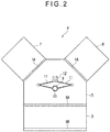
- Fig. 2 schematically shows a plan view of a manufacturing device 4 of the gas barrier film according to the first exemplary embodiment.
- the manufacturing device 4 of the gas barrier film includes a drier 5 set in the middle of the manufacturing device, a coater 6, a surface modifier 7, and a load lock chamber 8.
- the coater 6, the drier 5, the surface modifier 7, and the load lock chamber 8 are consecutively connected.
- Each of the coater 6, the surface modifier 7, and the load lock chamber 8 includes an opening for loading and unloading the molded product 3 (hereinafter, also referred to as a "transfer opening").
- the respective openings of the coater 6, the surface modifier 7, and the load lock chamber 8 are disposed facing the drier 5.
- the openings of the coater 6, the surface modifier 7, and the load lock chamber 8 are respectively blocked with a gate shutter 6A, a gate shutter 7A, and a gate shutter 8A which are openable and closeable partitions with respect to the drier 5.
- the drier 5 is configured to dry the gas barrier layer 2 formed of the gas barrier material applied by the coater 6.
- a transfer robot 9 as a transfer unit is disposed at the center of the drier 5.
- the transfer robot 9 includes: a column 10 rotatable by a motor (not shown); a pair of arms 11 horizontally projecting from the column 10; and a platform 12 attached to leading ends of the arms 11.
- the pair of arms 11 are expandable in a direction away from the column 10. By expanding the arms 11, the molded product 3 of the gas barrier film 1, which is mounted on the platform 12, can be carried into the coater 6, the surface modifier 7, and the load lock chamber 8.
- the load lock chamber 8 is connected to the drier 5.
- the load lock chamber 8 includes: an opening provided facing the drier 5; and a transfer gate 8B.
- the opening of the load lock chamber 8 is blocked with the gate shutter 8A as a partition.
- the molded product 3 is carried through the transfer gate 8B and a door of the transfer gate 8B is closed, and subsequently, the gate shutter 8A facing the drier 5 is opened and the molded product 3 is carried by the transfer robot 9.
- the coater 6 is configured to coat the molded product 3 with the gas barrier material to form the gas barrier layer 2.
- the coater 6 is connected to the drier 5.
- the gas barrier layer 2 before being subjected to heating is sometimes referred to as a gas barrier material layer or a polysilazane layer.
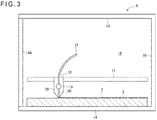
- the coater 6 includes a top board 13, a bottom board 14, a backboard 15, and a pair of sideboards 16.
- the coater 6 has an opening facing the drier 5. The opening of the coater 6 is blocked with the gate shutter 6A as a partition.
- An inside of the coater 6 is isolated from an outside. Since the inside of the coater 6 is isolated from the outside, undesired dust and the like can be prevented from adhering on the molded product 3 when the gas barrier layer 2 is formed on the molded product 3. In order to prevent a progress of a polysilazane conversion reaction in the inside of the coater 6 isolated from the outside, the gas barrier material is applied at an atmospheric pressure under nitrogen atmosphere.
- a pair of rails 17 are provided to the respective sideboards 16 in the coater 6.
- a die coater 18 is slidably attached to the pair of rails 17.
- the die coater 18 is configured to slide on the rails 17 by a drive motor (not shown).
- the die coater 18 includes a pair of dies 19 having narrow leading ends.
- a lip 20 is defined between the pair of dies 19.
- the gas barrier material such as polysilazane is applied through the lip 20 to a surface of the molded product 3.
- An interval between the pair of dies 19 is adjustable.
- a coating amount of the gas barrier material is adjustable by adjusting a width of the lip 20.
- the gas barrier material is fed into the lip 20 through a delivery hose 21.
- the gas barrier material is fed into the lip 20 through the delivery hose 21 from a tank (not shown) storing the gas barrier material by a pump configured to transfer the gas barrier material from the tank.
- the gas barrier layer 2 In order to apply the gas barrier layer 2 at a uniform thickness, for instance, it is preferable to blend an organic solvent and the like with a polysilazane compound to provide a liquid and apply the liquid onto the molded product 3.
- a coating method of the gas barrier material onto the molded product 3 in the coater 6 is not limited to the above method.
- various known methods such as a screen printing, knife coating, roll coating, inkjet coating, spin coating, spray coating, gravure coating and bar coating may be used.
- Heating conditions in the drier 5 preferably include a heating temperature ranging from 50 degrees C to 200 degrees C and a heating time ranging from 30 seconds to 60 minutes.
- the gas barrier layer 2 formed of polysilazane can be dried to form a film without damaging the molded product 3 and the like, so that the gas barrier film 1 having an extremely excellent gas barrier property can be stably produced.
- the heating conditions more preferably include the heating temperature ranging from 60 degrees C to 180 degrees C and the heating time ranging from 1 minute to 50 minutes, further preferably the heating temperature ranging from 70 degrees C to 150 degrees C and the heating time ranging from 2 minutes to 30 minutes.
- the heating conditions in the drier 5 are not limited to the above conditions.
- Various drying units are usable as the drier 5 as long as being capable of drying the gas barrier layer 2. Examples of the drying units include a hot air heater and an IR heater.
- the gas barrier layer 2 dried by the drier 5 is sometimes referred to as a modified polysilazane layer.
- the gas barrier material is dried at the atmospheric pressure under nitrogen atmosphere or under humidified atmosphere.
- the surface modifier 7 is configured to modify a surface of the gas barrier layer 2 (a modified polysilazane layer) dried by the drier 5.
- the surface modifier 7 injects plasma ions into the gas barrier layer 2 to modify the surface of the gas barrier layer 2.
- the surface modifier 7 includes a chamber including a top board 22, a bottom board 23, a backboard 24, and a pair of sideboards 25 opposed to each other.
- the surface modifier 7 is connected to the drier 5.
- the surface modifier 7 has an opening facing the drier 5. The opening of the surface modifier 7 is blocked with the gate shutter 7A as a partition.
- An inside of the surface modifier 7 is isolated from the outside.
- a gas inlet 26 penetrating the surface modifier 7 is provided on one of the sideboards 25 of the surface modifier 7.
- An exhaust outlet 27 is provided at an upper part of the backboard 24.
- An electrode 28 is provided in the inside of the surface modifier 7.
- a high-frequency power source 29A and a high-voltage pulse power source 29B are connected as a voltage applying unit to the electrode 28.
- the top board 22, the bottom board 23, the backboard 24, and the pair of sideboards 25 are made of a metallic plate and grounded.
- a basic method of injecting plasma ions using the surface modifier 7 is exemplified by a method of injecting ions (cations) present in plasma onto a surface of the modified polysilazane layer, the method including plasma generation under atmosphere containing a plasma generation gas (e.g., noble gas) and application of a negative high voltage pulse.
- a plasma generation gas e.g., noble gas
- the high-frequency power source 29A is turned on to generate plasma on the surface of the gas barrier layer 2 and subsequently the high-voltage pulse power source 29B is turned on to apply a high voltage to the electrode 28, thereby injecting plasma ions.
- the ions injected to the gas barrier layer 2 may be of any nature. Examples of the ions injected to the gas barrier layer 2 include ions shown in (a) to (k) below.
- the ions of at least one selected from the group consisting of hydrogen, nitrogen, oxygen, water, argon, helium, neon, xenon and krypton are preferable since the ions can be more easily injected to a predetermined depth of the gas barrier layer 2 to obtain the gas barrier film 1 stably having an excellent gas barrier property even though the gas barrier film 1 is a thin film.
- a pressure for injecting the plasma ions into the chamber when injecting the ions is preferably in a range from 0.01 Pa to 1 Pa.
- the pressure for injecting the plasma ions falls within the above range, the ions can be injected easily, efficiently and uniformly, so that the gas barrier film 1 having both of flexural resistance and gas barrier property can be efficiently formed.
- the pressure for injecting the plasma ions is more preferably in a range from 0.02 Pa to 0.8 Pa, further preferably in a range from 0.03 Pa to 0.6 Pa.
- a voltage applied when injecting the ions is preferably in a range from -1 kV to - 50 kV.
- the molded product 3 in the first exemplary embodiment is a thin plate-like component (film).
- a controller such as a computer is connected to the manufacturing device 4 of the gas barrier film.
- the controller is configured to perform not only a typical transfer process control of a semiconductor manufacturing device but also a coating amount control to adjust an opening size of the lip 20 of the die coater 18 in the coater 6, humidity adjustment and temperature control in the drier 5, and an electrode adjustment control and applied voltage adjustment control in the surface modifier 7.
- the manufacturing device 4 of the gas barrier film is used as a gas barrier layer-manufacturing device.
- the manufacturing method of the gas barrier film 1 includes: coating the surface of the molded product 3 with the gas barrier material in the coater 6; subsequently carrying the molded product 3 coated with the gas barrier material into the drier 5; drying the applied gas barrier material in the drier 5; carrying the molded product 3 to the surface modifier 7 after the gas barrier material is dried; and modifying a surface of the dried gas barrier material in the surface modifier 7.
- the molded product 3 is fed to the load lock chamber 8 through the transfer gate 8B and a door of the transfer gate 8B is closed. After the door is closed, the gate shutter 8A is opened and the molded product 3 is carried out of the load lock chamber 8 by the transfer robot 9.
- the transfer robot 9 revolves to carry the molded product 3 to a front of the coater 6. After the gate shutter 6A of the coater 6 is opened, the transfer robot 9 carries the molded product 3 to an inside of the coater 6.
- the gate shutter 6A is closed and the die coater 18 slides along the rails 17 and coats the surface of the molded product 3 with the gas barrier material to form the gas barrier layer 2.
- the gate shutter 6A is opened, the transfer robot 9 carries the molded product 3 out of the coater 6 to the drier 5 and holds the molded product 3 in the drier 5 for a predetermined time to dry the gas barrier material of the gas barrier layer 2.
- the transfer robot 9 transfers the molded product 3 to the front of the surface modifier 7.
- the transfer robot 9 carries the molded product 3 into the surface modifier 7.
- an argon gas or the like is injected into the surface modifier 7 through the gas inlet 26 while air inside the surface modifier 7 is removed through the exhaust outlet 27, and the high-frequency power source 29A and the high-voltage pulse power source 29B apply voltage, thereby injecting plasma ions.
- the transfer robot 9 After the plasma ions are injected, air is injected into the surface modifier 7.
- the transfer robot 9 When an internal pressure of the surface modifier 7 reaches the atmospheric pressure, the transfer robot 9 carries the molded product 3 out of the surface modifier 7 and carries the molded product 3 into the load lock chamber 8.
- An operator takes out the molded product 3 having the gas barrier layer 2 (i.e., the gas barrier film 1) through the transfer gate 8B.
- the molded product 3 can be transferred in a short time by the transfer robot 9, so that the gas barrier film 1 can be efficiently manufactured.
- a gas barrier film having a favorable gas barrier property can be manufactured.
- drying of the gas barrier layer 2 by the drier 5 can be started simply by the transfer robot 9 carrying the molded product 3 out of the coater 6. Accordingly, the gas barrier layer 2 can be dried in the drier 5 during being transferred from the coater 6 to surface modifier 7, so that the gas barrier film 1 can be further efficiently manufactured.
- the thin molded product 3 is transferred to the coater 6, the drier 5, and the surface modifier 7 using the transfer robot 9, thereby coating, drying and surface-modifying the gas barrier layer 2.
- a manufacturing device 30 of a gas barrier film according to the second exemplary embodiment is different from the manufacturing device 4 of the gas barrier film according to the first exemplary embodiment in that the manufacturing device 30 manufactures the gas barrier film by a so-called roll-to-roll method.
- the manufacturing device 30 of the gas barrier film in the exemplary embodiment transfers an elongated base material 3A and an elongated base material 3B, which are rolled as a molded product, using a drive roller 35 and a drive roller 36.
- the elongated base material 3A and the elongated base material 3B are subjected to processings in a coater 32, a drier 33, and a surface modifier 34.
- the elongated base material 3A and the elongated base material 3B are the molded product in a form of a film.
- the word of "elongated” means, for instance, that a length of the material is ten times or more as long as a width thereof.
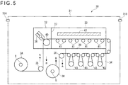
- the manufacturing device 30 of the gas barrier film in the exemplary embodiment includes a chamber 31, the coater 32, the drier 33, the surface modifier 34, the drive roller 35, the drive roller 36, a partition 37, and a partition 38.
- the manufacturing device 30 is entirely housed in the chamber 31. Specifically, the coater 32, the drier 33, the surface modifier 34, the drive roller 35, the drive roller 36, the partition 37, and the partition 38 are housed in the chamber 31.
- the chamber 31 has a gas inlet 31A and an exhaust outlet 31B each penetrating the chamber 31.
- an inside of the chamber 31 is at the atmospheric pressure under nitrogen atmosphere.
- the base materials in B direction in Fig. 5 since plasma ions are injected, the inside of the chamber 31 is at a low pressure under argon atmosphere. Conditions for each of the coating, drying and injecting plasma ions are the same as those in the first exemplary embodiment.
- the coater 32 includes a die coater 39 and a backup roller 40 as a support roller.
- the elongated base material 3A is wound around the backup roller 40.
- the die coater 39 is disposed opposite to the backup roller 40 across the elongated base material 3A.
- the die coater 39 coats the elongated base material 3A with the gas barrier material.
- the drier 33 includes a plurality of transfer rollers 41 and a heater 42.
- the plurality of transfer rollers 41 transfer the elongated base material 3A wound around a winding shaft X.
- the plurality of transfer rollers 41 are disposed opposite to the heater 42 across the elongated base material 3A.
- the gas barrier layer on the elongated base material 3A is dried by heat of the heater 42.
- the number of the transfer rollers 41 and a length of the heater 42 may be determined as needed according to a feeding speed of the elongated base material 3A and a heating temperature of the heater 42.
- the surface modifier 34 includes a plurality of plasma ion injecting units 43 as described in detail later.
- the surface modifier 34 is configured to inject plasma ions into the gas barrier layer formed on the elongated base material 3A.
- coating conditions in the coater 32, drying conditions in the drier 33, and surface-modifying conditions in the surface modifier 34 are the same as those in the first exemplary embodiment.
- Each of the drive roller 35 and the drive roller 36 has a drive motor (not shown) at its shaft.
- the elongated base material 3A in a roll can be fed by the drive roller 35 in the A direction and can be wound around a winding shaft Y by the drive roller 36.
- the drive roller 35 serves as a feeding roller and the drive roller 36 serves as a winding roller.
- the elongated base material 3B can be fed by the drive roller 36 in the B direction and can be wound around a winding shaft X by the drive roller 35.
- the drive roller 35 serves as a winding roller and the drive roller 36 serves as a feeding roller.
- the partition 37 is provided between the coater 32 and the drier 33.
- the partition 38 is provided between the drier 33 and the surface modifier 34. Processing units (the coater 32, the drier 33 and the surface modifier 34) are separated from each other with the partition 37 and the partition 38.
- Each of the partition 37 and the partition 38 has a slit through which the elongated base material 3A and the elongated base material 3B pass.
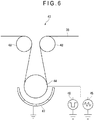
- Each of the plasma ion injecting units 43 forming the surface modifier 34 includes an electrode roller 44, a high-frequency power source 45, a high-voltage pulse power source 46, an electrode member 47 (electrode), and a guide roller 48 as shown in Fig. 6 .
- the elongated base material 3B is wound around the electrode roller 44.
- the electrode roller 44 is electrically connected to the high-frequency power source 45 and the high-voltage pulse power source 46 which serve as a voltage applying unit.
- a structure and an operation of each of the high-frequency power source 45 and the high-voltage pulse power source 46 are the same as those in the first exemplary embodiment.
- the electrode member 47 is disposed opposite to the electrode roller 44 across the elongated base material 3B.
- the electrode member 47 is disposed along an outer circumference of the electrode roller 44 in a manner to surround the electrode roller 44.
- the electrode member 47 is grounded.
- the guide roller 48 is configured to introduce the elongated base material 3B to the electrode roller 44 and guide the elongated base material 3B to the next one of the plasma ion injecting units 43.
- a plurality of plasma ion injecting units 43 are used.
- the number of the plasma ion injecting units 43 may be set as needed according to a required frequency of injecting plasma ions.
- a controller such as a computer is connected to the manufacturing device 30 of the gas barrier film.
- the controller is configured to perform not only feeding and winding control of the elongated base material 3A and the elongated base material 3B and a coating amount control of the gas barrier material in the coater 32 but also humid adjustment and temperature control in the drier 33, and an electrode adjustment control and applied voltage adjustment control in the surface modifier 7.
- the manufacturing device 30 of the gas barrier film is used as a gas barrier layer-manufacturing device.
- the manufacturing method of the gas barrier film according to the exemplary embodiment includes: feeding the elongated base material 3A; coating the surface of the elongated base material 3A with the gas barrier material in the coater 32; carrying the elongated base material 3A coated with the gas barrier material into the drier 33; drying the coated gas barrier material in the drier 33; winding the elongated base material 3A after the gas barrier material is dried; subsequently feeding the wound elongated base material 3A as the elongated base material 3B; carrying the elongated base material 3B to the surface modifier 34; and modifying a surface of the dried gas barrier material in the surface modifier 34.
- a step of changing an atmosphere inside the gas barrier layer-manufacturing device from the atmosphere in the drying is preferably performed.
- Changing of the atmosphere inside the gas barrier layer-manufacturing device is exemplified by changing a nitrogen atmosphere to an argon atmosphere.
- an inside of the chamber 31 is set at the atmospheric pressure under nitrogen atmosphere.
- the drive roller 35 is rotated in the feeding direction to feed the elongated base material 3A, which is wound around the winding shaft X, in the A direction.
- the die coater 39 of the coater 32 coats the elongated base material 3A with the gas barrier material. After coating of the gas barrier material, the gas barrier layer is dried by the heater 42 of the drier 33.
- the elongated base material 3A is wound around the winding shaft Y by the drive roller 36.
- a rotation direction of the drive roller 36 is reversed to feed the elongated base material 3B, which is wound around the winding shaft Y, in the B direction.
- the surface modifier 34 injects plasma ions into the gas barrier layer on the elongated base material 3B to modify the surface of the gas barrier layer.
- the elongated base material 3B is wound around the winding shaft X by the drive roller 35.
- the following advantages are obtainable in addition to the above-described advantages of the first exemplary embodiment.
- the die coater 39 can continuously coat the elongated base material 3A fed by the drive roller 35 with the gas barrier material
- the heater 42 can dry the gas barrier material on the transfer rollers 41
- the high-frequency power source 45 and the high-voltage pulse power source 46 can modify the surface of the gas barrier layer on the elongated base material 3B fed by the drive roller 36. Accordingly, with the manufacturing device and the manufacturing method according to the exemplary embodiment, a gas barrier film can be manufactured continuously and quickly.
- a space where the transfer robot 9 is disposed also functions as the drier 5.
- the transfer robot 9 as the transfer unit is housed in the drier 5.
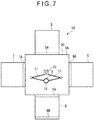
- a manufacturing device 50 of a gas barrier film according to the third exemplary embodiment is different from the manufacturing device 4 of the gas barrier film according to the first exemplary embodiment in that the drier 5 is independent of a space 9A where the transfer robot 9 is disposed.
- the manufacturing device 50 of the gas barrier film includes a transfer chamber 90 provided in the middle of the manufacturing device, the drier 5, the coater 6, the surface modifier 7, and the load lock chamber 8.
- the transfer robot 9 is disposed in the space 9A.
- a pair of arms of the transfer robot 9 are expandable in a direction away from the column 10. By expanding the arms 11, the molded product 3 mounted on the platform 12 can be carried into the drier 5, the coater 6, the surface modifier 7, and the load lock chamber 8.
- the transfer chamber 90, the coater 6, the drier 5, the surface modifier 7, and the load lock chamber 8 are consecutively connected.
- the drier 5 is connected to the transfer chamber 90.
- the drier 5 has an opening facing the space 9A of the transfer chamber 90.
- the opening of the drier 5 is blocked with a gate shutter 5A.
- the coater 6 is connected to the transfer chamber 90.
- the coater 6 has an opening facing the space 9A of the transfer chamber 90. The opening of the coater 6 is blocked with the gate shutter 6A.
- the surface modifier 7 is connected to the transfer chamber 90.
- the surface modifier 7 has an opening facing the space 9A of the transfer chamber 90. The opening of the surface modifier 7 is blocked with the gate shutter 7A.
- the load lock chamber 8 is connected to the transfer chamber 90.
- the load lock chamber 8 includes: an opening provided facing the transfer chamber 90; and the transfer gate 8B. The opening of the load lock chamber 8 is blocked with the gate shutter 8A.
- the coater 6, the drier 5, the surface modifier 7 and the load lock chamber 8 are consecutively connected in an anticlockwise order around the space 9A of the transfer chamber 90.
- the structure and the operation of the coater 6, the drier 5, the surface modifier 7 and the load lock chamber 8 are the same as those in the first exemplary embodiment.
- the manufacturing device 50 of the gas barrier film is used as a gas barrier layer-manufacturing device.
- the molded product 3 in the third exemplary embodiment is a thin plate-like component.
- the manufacturing method of the gas barrier film according to the third exemplary embodiment includes: coating the surface of the molded product 3 with the gas barrier material in the coater 6; transferring the molded product 3 coated with the gas barrier material into the transfer chamber 90 through the transfer opening of the drier 5 and transferring the molded product 3 transferred from the coater 6 into the drier 5 through the transfer opening of the drier 5; drying the coated gas barrier material in the drier 5; after the gas barrier material is dried, transferring the molded product 3 into the transfer chamber 90 through the transfer opening of the drier 5 and transferring the molded product 3 transferred from the drier 5 into the surface modifier 7 through the transfer opening of the surface modifier 7; and modifying a surface of the dried gas barrier material in the surface modifier 7.
- the transfer robot 9 carries the molded product 3 to a front of the drier 5. After the gate shutter 5A is opened, the transfer robot 9 carries the molded product 3 into the drier 5 and further places the molded product 3 at a predetermined position.
- the gas barrier layer 2 is dried in the drier 5. Heating conditions in the drier 5 are the same as those in the first exemplary embodiment.
- the gate shutter 5A is opened, the transfer robot 9 carries the molded product 3 out of the drier 5 and then carries the molded product 3 into the surface modifier 7, where plasma ions injection is performed in the same manner as in the first exemplary embodiment.
- a step of taking out the gas barrier film 1 through the transfer gate 8B is the same as in the first exemplary embodiment, an explanation of the step will be omitted.
- the same operation and the advantages as in the first exemplary embodiment are obtainable.
- the gas barrier film can be taken out of the manufacturing device through the transfer chamber 90 and the load lock chamber 8 without passing through the drier 5.
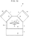
- Fig. 8 shows a schematic plan view of a structure of a manufacturing device 60 of a gas barrier film according to the fourth exemplary embodiment.
- the manufacturing device 60 of the gas barrier film is mainly different from the manufacturing device 4 of the gas barrier film according to the first exemplary embodiment in that the manufacturing device 60 includes a measuring unit 100 for measuring the gas barrier layer 2.
- the manufacturing device 60 of the gas barrier film includes the drier 5 set in the middle of the manufacturing device, the coater 6, the surface modifier 7, the load lock chamber 8, and the measuring unit 100.
- a pair of arms of the transfer robot 9 are expandable in a direction away from the column 10. By expanding the arms 11, the molded product 3 mounted on the platform 12 can be carried into the coater 6, the surface modifier 7, the measuring unit 100, and the load lock chamber 8.
- the structure and the operation of the coater 6, the drier 5, the surface modifier 7 and the load lock chamber 8 are the same as those in the first exemplary embodiment.
- the measuring unit 100 is configured to measure at least one of the gas barrier material applied by the coater 6, the gas barrier material dried in the drier 5, and the gas barrier material modified in the surface modifier 7. In other words, the measuring unit 100 measures the gas barrier layer 2 formed on the molded product 3.
- the measuring unit 100 is connected to the drier 5. As shown in Fig. 8 , a connection portion between the measuring unit 100 and the drier 5 is positioned between a connection portion between the coater 6 and the drier 5 and a connection portion between the surface modifier 7 and the drier 5.
- the measuring unit 100 has an opening facing the drier 5.
- the opening of the drier 100 is blocked with a partition in a form of a gate shutter 100A.
- a measurement item(s) of the gas barrier layer 2 by the measuring unit 100 is preferably at least one measurement item selected from the group consisting of a refractive index, light transmissivity, light reflectivity, chromaticity, film composition, film density, film defects and film thickness.
- a refractive index of the gas barrier layer 2 can be measured according to spectroscopic ellipsometry.
- a light transmissivity of the gas barrier layer 2 can be measured according to a spectral transmittance measurement method.
- a light reflectivity of the gas barrier layer 2 can be measured according to a spectral reflectance measurement method.
- a chromaticity of the gas barrier layer 2 can be measured according to spectral colorimetry.
- a film composition of the gas barrier layer 2 can be measured according to at least one of an XPS measurement method (X-ray photoelectron spectroscopy) and an IR measurement method (infrared spectroscopy).
- XPS is an abbreviation of X-ray Photoelectron Spectroscopy.
- IR is an abbreviation of Infrared Spectroscopy.
- a film density of the gas barrier layer 2 can be measured according to an XRR measurement method (X-ray reflection measurement method).
- XRR is an abbreviation of X-ray Reflection.
- Film defects of the gas barrier layer 2 can be measured according to a method of taking an image of the gas barrier layer 2 using at least one of a transmitted light and a reflected light and subjecting the taken image of the gas barrier layer 2 to an image processing.
- a film thickness of the gas barrier layer 2 can be measured according to at least one of the spectroscopic ellipsometry, the spectral reflectance measurement method, fluorescent X-ray spectroscopy, and a measurement method using a contact step gauge.
- a measuring device (not shown) is housed inside the measuring unit 100.
- the measuring device is appropriately selected depending on the measurement items and the measurement methods.
- the measuring device housed inside the measuring unit 100 is not limited to a single type. It is only necessary that an appropriate measurement device(s) required according to a type and the number of the measurement items is housed inside the measuring unit 100.
- a controller such as a computer is connected to the manufacturing device 60 of the gas barrier film in the same manner as in the first exemplary embodiment.
- the controller in the fourth exemplary embodiment can conduct not only the control explained in the first exemplary embodiment but also, for instance, a control of the measuring device of the gas barrier layer 2 in the measuring unit 100 and collection and analysis of measurement data.
- the manufacturing device 60 of the gas barrier film is used as a gas barrier layer-manufacturing device.
- the molded product 3 in the fourth exemplary embodiment is a thin plate-like component.
- the manufacturing method of the gas barrier film according to the fourth exemplary embodiment further includes measuring at least one of the gas barrier material applied by the coater 6, the gas barrier material dried by the drier 5, and the gas barrier material modified by the surface modifier 7.
- the manufacturing method of the gas barrier film according to the fourth exemplary embodiment it is preferable to measure the gas barrier material before the gas barrier material is modified in the surface modifier 7.
- the transfer robot 9 After the drying in the drier 5 is finished, the transfer robot 9 carries the molded product 3 to a front of the measuring unit 100. After the gate shutter 100A is opened, the transfer robot 9 carries the molded product 3 into the measuring unit 100 and further places the molded product 3 at a predetermined position. The gas barrier layer 2 is measured in the measuring unit 100. Measurement items to be measured after the gas barrier layer 2 is dried and before the gas barrier layer 2 is subjected to the surface modification are as described above.
- the gas barrier layer 2 After the gas barrier layer 2 is dried and before the gas barrier layer 2 is subjected to the surface modification, it is preferable to measure a modified polysilazane layer and control a progress degree of a conversion reaction of a polysilazane film and a coating film thickness.
- the progress degree of the conversion reaction can be checked by measuring at least one of a refractive index, light reflectivity, film composition and film density of the modified polysilazane layer. It is preferable to check the progress degree of the conversion reaction of the polysilazane film by measuring the refractive index. Data on the refractive index obtained by the refractive index measurement is preferably fed back to the above-described controller. In this arrangement, the controller can suitably control the heating conditions in the drier 5 based on the refractive index data.
- the refractive index of the modified polysilazane layer after the gas barrier layer 2 is dried and before the gas barrier layer 2 is subjected to the surface modification is controlled in a range from 1.48 to 1.70.
- a gas barrier film having the gas barrier layer 2 excellent in the gas barrier property e.g., a steam transmissivity), transparency (e.g., total light transmissivity) and the like can be obtained with the plasma ion injection in the surface modification step.
- the refractive index of the modified polysilazane layer is less than 1.48, the steam transmissivity and an oxygen transmissivity of the gas barrier film sometimes become excessively high.
- the refractive index of the modified polysilazane layer exceeds 1.70, the transparency (total light transmissivity) of the gas barrier film is sometimes excessively lowered or the gas barrier film is sometimes colored.
- the refractive index of the modified polysilazane layer after the gas barrier layer 2 is dried and before the gas barrier layer 2 is subjected to the surface modification is controlled in a range from 1.49 to 1.65, further preferably in a range from 1.50 to 1.60.
- the gate shutter 100A is opened and the transfer robot 9 transfers the molded product 3 from the measuring unit 100 into the surface modifier 7.
- the transfer robot 9 transfers the molded product 3 from the surface modifier 7 to the measuring unit 100 and measures the gas barrier layer 2 subjected to the surface modification.
- a modification degree of the modified polysilazane layer can be checked by measuring at least one of the refractive index, light transmissivity, light reflectivity, chromaticity, film composition and film density of the modified polysilazane layer.
- the modification degree of the modified polysilazane layer is preferably checked by measuring the light transmissivity.
- Data on the light transmissivity obtained by the light transmissivity measurement is preferably fed back to the above-described controller.
- the controller can suitably control conditions for the plasma ion injection in the surface modifier 7 based on the light transmissivity data.
- the transfer robot 9 transfers the molded product 3 from the measuring unit 100. Since a subsequent procedure until the step of taking out the gas barrier film 1 through the transfer gate 8B is the same as in the first exemplary embodiment, an explanation of the subsequent procedure will be omitted.
- a film state after the ion injection greatly depends on a state of the modified polysilazane layer before the ion injection (i.e., after the coating and before the surface modification). It is considered that a control of the film state after the surface modification is an important test item for judging effectiveness of the surface modification.
- the state of the gas barrier layer can be measured in a manufacture line from the coating step through the drying step to the modification step (i.e., in-line measurement).
- the film can be continuously evaluated and controlled and the gas barrier film can be continuously manufactured in a series from the coating of the gas barrier material to the ion injecting.
- the progress degree of the conversion reaction of the polysilazane film and the coating film thickness of the polysilazane film can be suitably controlled. Consequently, according to the fourth exemplary embodiment, the gas barrier film having the gas barrier layer 2 excellent in the gas barrier property (e.g., a steam transmissivity), transparency (e.g., total light transmissivity) and the like can be obtained.
- a steam transmissivity e.g., a steam transmissivity
- transparency e.g., total light transmissivity
- the drier 5, the coater 6, the surface modifier 7, and the measuring unit 100 are separated from each other by the gate shutters as the partitions. Accordingly, it is easy to keep the inside of the measuring unit 100 in a state suitable for the measurement, so that accuracy and quickness of the measurement can be improved.
- Fig. 9 shows a schematic plan view of a structure of a manufacturing device 70 of a gas barrier film according to the fifth exemplary embodiment.
- the manufacturing device 70 of the gas barrier film is mainly different from the manufacturing device 50 of the gas barrier film according to the third exemplary embodiment in that the manufacturing device 70 includes the measuring unit 100 for measuring the gas barrier layer 2.
- the manufacturing device 70 of the gas barrier film includes a transfer chamber 90A provided in the middle of the manufacturing device, the drier 5, the coater 6, the surface modifier 7, the load lock chamber 8, and the measuring unit 100.
- the structure and the operation of the coater 6, the drier 5, the surface modifier 7 and the load lock chamber 8 are the same as those in the first or the third exemplary embodiment.
- the structure and the operation of the measuring unit 100 and the measurement items of the gas barrier layer 2 in the measuring unit 100 are the same as those in the fourth exemplary embodiment.
- a controller (not shown) such as a computer is connected to the manufacturing device 70 of the gas barrier film in the same manner as in the fourth exemplary embodiment.
- the transfer chamber 90A, the coater 6, the drier 5, the surface modifier 7, the load lock chamber 8, and the measuring unit 100 are consecutively connected.
- the transfer chamber 90A is formed substantially in a pentagon in a plan view as shown in the schematic plan view of Fig. 9 .
- An inside of the transfer chamber 90A is defined as the space 9A.
- the transfer robot 9 is disposed in the space 9A.
- a pair of arms of the transfer robot 9 are expandable in a direction away from the column 10. By expanding the arms 11, the molded product 3 mounted on the platform 12 can be carried into the coater 6, the drier 5, the surface modifier 7, the measuring unit 100, and the load lock chamber 8.
- the coater 6, the drier 5, the surface modifier 7, the load lock chamber 8, and the measuring unit 100 are respectively connected to portions of the transfer chamber 90A corresponding to sides of the substantial pentagon in a plan view.
- the coater 6, the drier 5, the surface modifier 7, the load lock chamber 8, and the measuring unit 100 respectively have openings facing the space 9A of the transfer chamber 90A.
- the respective openings of the coater 6, the drier 5, the surface modifier 7, the load lock chamber 8, and the measuring unit 100 are respectively blocked with the gate shutter 6A, the gate shutter 5A, the gate shutter 7A, the gate shutter 8A, and the gate shutter 100A.
- the manufacturing device 70 of the gas barrier film is used as a gas barrier layer-manufacturing device.
- the molded product 3 in the fifth exemplary embodiment is a thin plate-like component.
- the manufacturing method of the gas barrier film according to the fifth exemplary embodiment further includes measuring at least one of the gas barrier material applied by the coater 6, the gas barrier material dried by the drier 5, and the gas barrier material modified by the surface modifier 7. Further, in the manufacturing method of the gas barrier film according to the fifth exemplary embodiment, the molded product 3 is transferred to the measuring unit 100 when measuring the gas barrier material.
- the manufacturing method of the gas barrier film according to the fifth exemplary embodiment it is preferable to measure the gas barrier material before the gas barrier material is modified in the surface modifier 7.
- the transfer robot 9 After the drying step is finished, the transfer robot 9 carries the molded product 3 to a front of the measuring unit 100. After the gate shutter 100A is opened, the transfer robot 9 carries the molded product 3 into the measuring unit 100 and further places the molded product 3 at a predetermined position. Since the measurement in the measuring unit 100 is the same as in the fourth exemplary embodiment, an explanation of the measurement will be omitted.
- steps subsequent to the measurement of the gas barrier layer 2 specifically, the step of injecting plasma ions in the surface modifier 7 and the step of measuring the gas barrier layer 2 after the surface modification and taking out the gas barrier film 1 through the transfer gate 8B are the same as in the previous exemplary embodiments, an explanation of the step will be omitted.
- the gas barrier film can be taken out of the manufacturing device through the transfer chamber 90 and the load lock chamber 8 without passing through the drier 5.
- Fig. 10 shows a schematic plan view of a structure of a manufacturing device 80 of a gas barrier film according to the sixth exemplary embodiment.
- the manufacturing device 80 of the gas barrier film in the sixth exemplary embodiment is mainly different from the manufacturing device 4 of the gas barrier film according to the first exemplary embodiment in that the manufacturing device 80 includes measuring units 101, 102 and 103 for measuring the gas barrier layer 2.
- the structure and the operation of the coater 6, the drier 5, the surface modifier 7 and the load lock chamber 8 are the same as those in the first exemplary embodiment.
- the sixth exemplary embodiment is mainly different from the fourth exemplary embodiment and the fifth exemplary embodiment in that the coater 6, the drier 5, and the surface modifier 7 house the respective measuring units in the manufacturing device 80 of the gas barrier film according to the sixth exemplary embodiment, whereas the measuring unit 100 is independent of the coater 6, the drier 5, and the surface modifier 7 in the manufacturing device of the gas barrier film in the fourth and fifth exemplary embodiments.
- the coater 6 has the measuring unit 101
- the drier 5 has the measuring unit 103
- the surface modifier 7 has the measuring unit 102.
- a setting position of the measuring unit 101 is not particularly limited, as long as the measuring unit 101 is set inside the coater 6. It is only required to select the setting position depending on the measurement items in the coater 6. For instance, as shown in Fig. 11 , the measuring unit 101 may be attached to the top board 13 of the coater 6.
- a setting position of the measuring unit 102 is not particularly limited, as long as the measuring unit 102 is set inside the surface modifier 7. It is only required to select the setting position depending on the measurement items in the surface modifier 7. For instance, as shown in Fig. 12 , the measuring unit 102 may be attached to the top board 22 of the surface modifier 7.
- the measuring units 101, 102 and 103 are not limited to the measuring unit 100 as long as the measuring units 101, 102 and 103 can measure the same measurement items as those of the measuring unit 100.
- a measuring device similar to the measuring device used as the measuring unit 100 is also usable as the measuring units 101, 102 and 103.
- a controller such as a computer is connected to the manufacturing device 80 of the gas barrier film in the same manner as in the fourth exemplary embodiment.
- the manufacturing device 80 of the gas barrier film is used as a gas barrier layer-manufacturing device.
- the molded product 3 in the sixth exemplary embodiment is a thin plate-like component.
- the manufacturing method of the gas barrier film according to the sixth exemplary embodiment further includes measuring at least one of the gas barrier material applied by the coater 6, the gas barrier material dried by the drier 5, and the gas barrier material modified by the surface modifier 7.
- at least one of the measuring units housed in the drier 5, the coater 6 and the surface modifier 7 measures the gas barrier material.
- the manufacturing method of the gas barrier film according to the sixth exemplary embodiment it is preferable to measure the gas barrier material before the gas barrier material is modified in the surface modifier 7.
- the manufacturing device 80 of the gas barrier film is different from the manufacturing device 4 of the gas barrier film according to the first exemplary embodiment in that at least one of the measuring units 101, 102 and 103 can measure the gas barrier layer 2.
- the measuring unit 101 of the coater 6 preferably measures a film thickness of the gas barrier layer 2 before the gas barrier layer 2 is dried.
- the measuring unit 102 of the drier 5 can measure the gas barrier layer 2 before and after the gas barrier layer 2 is subjected to the surface modification.
- the measuring unit 103 of the surface modifier 7 can measure the gas barrier layer 2 before and after the gas barrier layer 2 is subjected to the surface modification.
- the measuring units are respectively housed in the drier 5, the coater 6 and the surface modifier 7, the measurement can be quickly started each time the processing is finished in each of the drier 5, the coater 6 and the surface modifier 7.
- Fig. 13 shows a schematic view of a structure of a manufacturing device 30A of a gas barrier film according to the seventh exemplary embodiment.
- the manufacturing device 30A of the gas barrier film has the same structure as that of the manufacturing device 30 of the gas barrier film according to the second exemplary embodiment, and further includes a measuring unit 104 and a measuring unit 105.
- the measuring unit 104 is disposed between the drier 33 and the surface modifier 34.
- the measuring units 104 and 105 may have any arrangement as long as the measuring units 104 and 105 can measure the same measurement item as those of the measuring unit 100. For instance, a measuring device similar to the measuring device used as the measuring unit 100 is also usable as the measuring units 104 and 105.
- the structure and the operation of the chamber 31, the coater 32, the drier 33, the surface modifier 34, the drive roller 35, the drive roller 36, the partition 37, and the partition 38 are the same as those in the second exemplary embodiment.
- a controller such as a computer is also connected to the manufacturing device 30A of the gas barrier film in the same manner as in the second exemplary embodiment.
- the manufacturing device 30A of the gas barrier film is used as a gas barrier layer-manufacturing device.
- the manufacturing method of the elongated gas barrier film according to the seventh exemplary embodiment further includes measuring at least one of the gas barrier material applied by the coater 6, the gas barrier material dried by the drier 5, and the gas barrier material modified by the surface modifier 7.
- the manufacturing method of the gas barrier film according to the seventh exemplary embodiment it is preferable to measure the gas barrier material before drying the gas barrier material applied by the coater 6.
- the seventh exemplary embodiment is the same as in the second exemplary embodiment except for the measurement in the measuring units 104 and 105, an explanation of the same structure will be omitted.
- the measuring unit 104 measures the gas barrier layer 2 (the modified polysilazane layer) before being subjected to the surface modification. Also while the elongated base material 3B after being subjected to the surface modification 34 by the surface modifier 34 is transferred toward the drier 33, the measuring unit 104 can measure the gas barrier layer 2 after being subjected to the surface modification.
- the measuring unit 105 is disposed between the surface modifier 34 and the winding shaft Y. After the elongated base material 3A is subjected to the surface modification in the surface modifier 34 and before the elongated base material 3A is wound around the winding shaft Y, the measuring unit 105 measures the gas barrier layer 2 after being subjected to the surface modification.
- the seventh exemplary embodiment the following advantages are obtainable in addition to the above-described advantages of the second exemplary embodiment.
- the gas barrier material of the elongated base material 3A can be measured while the elongated base material 3A is transferred from the drier 33 to the surface modifier 34. Accordingly, it can be checked in advance whether the gas barrier layer 2 is in a state suitable for the surface modification.
- the manufacturing device and the manufacturing method according to the seventh exemplary embodiment by constantly controlling the film state in a roll-to-roll manufacture line, the film can be continuously evaluated and controlled and the gas barrier film can be continuously manufactured in a series from the coating of the gas barrier material to the ion injecting.
- the manufacturing device and the manufacturing method according to the seventh exemplary embodiment even in the roll-to-roll manufacture line, after the gas barrier layer 2 is dried and before the gas barrier layer 2 is subjected to the surface modification, the progress degree of the conversion reaction of the polysilazane film and the coating film thickness of the polysilazane film can be suitably controlled. Consequently, the gas barrier film having the gas barrier layer 2 excellent in the gas barrier property (e.g., a steam transmissivity), transparency (e.g., total light transmissivity) and the like can be manufactured by the roll-to-roll process.
- a steam transmissivity e.g., a steam transmissivity
- transparency e.g., total light transmissivity
- the manufacturing method and the manufacturing device mainly for manufacturing the gas barrier film are described as an example, but the method and the device are not limited those for manufacturing the gas barrier film.
- the manufacturing method and the manufacturing device described in the above exemplary embodiments are applicable for the molded product in a form of various containers and various electronic device components.
- the scope of the invention is not limited to the embodiment of forming a single gas barrier layer on the molded product, but encompasses an arrangement in which one or more gas barrier layers are further laminated on the formed gas barrier layer.
- a molded product having a gas barrier layer with a predetermined thickness can be manufactured by laminating the gas barrier layers.
- the molded product needs not to be carried out of the load lock chamber but may be again transferred to the coater, the drier, and the surface modifier in this order, whereby another gas barrier layer can be laminated on the previously formed gas barrier layer.
- the elongated base material subjected to the surface modification may be again fed in the A direction to be subjected to the processings in the coater and the drier, and further fed in the B direction to be subjected to the processing in the surface modifier, whereby another gas barrier layer can be laminated on the previously formed gas barrier layer.
- the measuring unit measures the film state of each of the gas barrier layers each time the gas barrier layer is formed.
- the measuring unit measures the gas barrier layer before and after the surface modification step.
- the scope of the invention is not limited to such embodiments.
- the coater, the drier, and the surface modifier have the respective measuring units.
- the scope of the invention is not limited to such an embodiment.
- the manufacturing device of the gas barrier film provided with the measuring unit includes a measuring unit in any one of the coater, the drier, and the surface modifier.
- the measuring unit is not independent of the coater, the drier, and the surface modifier, at least one of the coater, the drier, and the surface modifier preferably includes the measuring unit.
- the coater has the measuring unit but the drier and the surface modifier do not have the measuring unit.
- the drier has the measuring unit but the coater and the surface modifier do not have the measuring unit.
- the surface modifier has the measuring unit but the coater and the drier do not have the measuring unit.
- a setting position of the measuring unit is not particularly limited as long as the modified polysilazane layer is measurable.
- the manufacturing device 30A of the gas barrier film having the measuring units 104 and 105 is described as an example.
- the scope of the invention is not limited to such an embodiment.
- it is preferable that such a roll-to-roll manufacturing device as shown in the third and seventh exemplary embodiments has at least one measuring unit. It is preferable to measure the modified polysilazane layer after the gas barrier layer is dried and before the gas barrier layer is subjected to the surface modification.
- a setting position of the measuring unit in a roll-to-roll manufacturing device is not particularly limited as long as the modified polysilazane layer is measurable.
- high-voltage pulse power source 47... electrode member, 48...guide roller, 50...manufacturing device of a gas barrier film, 60...manufacturing device of a gas barrier film, 70...manufacturing device of a gas barrier film, 80...manufacturing device of a gas barrier film, 90...transfer chamber, 90A...transfer chamber, 100...measuring unit, 100A...gate shutter, 101...measuring unit, 102...measuring unit, 103...measuring unit, 104...measuring unit, 105...measuring unit, X...winding shaft, Y...winding shaft.
Landscapes
- Application Of Or Painting With Fluid Materials (AREA)
- Laminated Bodies (AREA)
- Coating Apparatus (AREA)
- Electroluminescent Light Sources (AREA)
- Coating Of Shaped Articles Made Of Macromolecular Substances (AREA)
Abstract
Description
- The present invention relates to a manufacturing device of a molded product provided with a gas barrier layer.
- In order to provide an alternative of a substrate in a form of glass used in an organic EL device, there have been typically proposed a manufacturing method and the like of a gas barrier film having an excellent gas barrier property in a short manufacturing time (see, for instance, Patent Literature 1).
- More specifically, the manufacturing method of the gas barrier film includes: coating at least one surface of a base material with a polysilazane-containing liquid; heating and drying the base material to provide a polysilazane film; and subjecting the polysilazane film to an atmospheric pressure plasma processing or a vacuum plasma processing.
- Patent Literature 1:
JP2007-237588A - In the technique disclosed in
Patent Literature 1, since the coating step, the heating-drying step, and the vacuum plasma processing step are each independently performed, productivity is deteriorated and polysilazane in the coating liquid adversely reacts with moisture in the air to easily generate defects on the gas barrier film. - An object of the invention is to provide a manufacturing device configured to efficiently manufacture a molded product provided with a gas barrier layer (hereinafter, also referred to as a "gas barrier layer-formed product) having a favorable gas barrier property.
- According to an aspect of the invention, a manufacturing device of a molded product provided with a gas barrier layer, in which the gas barrier layer is formed on a surface of the molded product, includes: a coater configured to coat the molded product with a gas barrier material; a drier configured to dry the gas barrier material applied by the coater; a surface modifier configured to modify a surface of the gas barrier material dried in the drier, and a transfer unit configured to transfer the molded product to the coater, the drier, and the surface modifier, in which the coater, the drier, and the surface modifier are consecutively connected, and the coater, the drier, and the surface modifier are separated from each other by partitions.
- With the manufacturing device according to the above aspect of the invention, since the coater, the drier, and the surface modifier are consecutively connected, the molded product can be transferred in a short time by the transfer unit, so that the molded product provided with the gas barrier layer can be efficiently manufactured.
- Moreover, with the manufacturing device according to the above aspect of the invention, since a transfer time of the molded product is shortened, a reaction between the gas barrier layer and moisture in the air during the transfer is reducible, so that generation of defects or the like on the gas barrier layer is preventable.
- In other words, in the above arrangement, a manufacturing device configured to efficiently manufacture a molded product provided with a gas barrier layer having a favorable gas barrier property can be provided.
- In the manufacturing device according to the above aspect of the invention, preferably, the drier is disposed at a center of the manufacturing device, a transfer opening of the coater and a transfer opening of the surface modifier are positioned facing the drier, and the transfer unit is disposed in the drier.
- With the above arrangement, after the gas barrier layer is formed on the surface of the molded product by the coater, drying of the gas barrier layer by the drier can be started simply by the transfer unit carrying the molded product out of the coater. Accordingly, the gas barrier layer can be dried in the drier during being transferred from the coater to the surface modifier, so that the gas barrier layer-formed product can be further efficiently manufactured.
- In the manufacturing device according to the above aspect of the invention, preferably, a transfer opening of the coater, a transfer opening of the drier, and a transfer opening of the surface modifier face a space in which the transfer unit is disposed.
- With the above arrangement, the same operation and the advantages as the above are obtainable.
- In the manufacturing device according to the above aspect of the invention, preferably, the molded product is an elongated base material in a form of a roll, the transfer unit includes: a feeding roller configured to feed the elongated base material; and a winding roller configured to wind the elongated base material, the coater includes: a support roller supporting the elongated base material; and a die coater that is disposed opposite to the support roller across the elongated base material and is configured to coat the elongated base material with the gas barrier material, and the drier includes: a plurality of transfer rollers configured to transfer the elongated base material; and a heater disposed opposite to the plurality of transfer rollers across the elongated base material.
- With the above arrangement, the elongated base material fed by the feeding roller can be coated with the gas barrier material by the die coater, and the gas barrier material can be dried on the transfer rollers by the heater, so that the gas barrier layer-formed product can be quickly manufactured.
- In the manufacturing device according to the above aspect of the invention, preferably, the surface modifier includes: an electrode roller configured to be wound with the elongated base material; a voltage applying unit configured to apply a voltage onto the electrode roller; and an electrode disposed opposite to the electrode roller across the elongated base material.
- With the above arrangement, since the surface modification of the gas barrier layer formed on the elongated base material can be conducted during the transfer of the elongated base material, all of the coating step, the drying step and the surface modification step can be continuously conducted during the transfer of the elongated base material, so that the molded product provided with the gas barrier layer can be more quickly manufactured.
- In the manufacturing device according to the above aspect of the invention, preferably, the manufacturing device further includes a measuring unit configured to measure at least one of the gas barrier material applied by the coater, the gas barrier material dried by the drier, and the gas barrier material modified by the surface modifier.
- With the above arrangement, the state of the gas barrier layer can be measured in a manufacture line after each of the coating step, the drying step, and the modification step (i.e., in-line measurement). By constantly controlling the film state in the manufacture line of the gas barrier layer-formed product, the film can be continuously evaluated and controlled and the molded product provided with the gas barrier layer can be continuously manufactured in a series from the coating of the gas barrier material to the ion injecting.
- In the manufacturing device according to the above aspect of the invention, preferably, the measuring unit is consecutively connected to the coater, the drier, and the surface modifier, and the coater, the drier, the surface modifier, and the measuring unit are separated from each other by the partitions.
- In the manufacturing device according to the above aspect of the invention, preferably, the measuring unit is disposed inside at least one of the coater, the drier, and the surface modifier.
- With the above arrangement, since the coater, the drier, the surface modifier and the measuring unit are consecutively connected, the gas barrier layer-formed product can be efficiently manufactured in the same manner as described above even by the manufacturing device installed with the in-line measurement. Further, with the above arrangement, generation of defects and the like on the gas barrier layer is preventable in the same manner as described above.
- In the manufacturing device according to the above aspect of the invention, the molded product is preferably transferred to the coater, the drier, and the measuring unit in this order.
- With the above arrangement, since the molded product is transferred to the coater, the drier, and the measuring unit in this order, a state of the gas barrier layer before the surface modification is measurable. Accordingly, it can be checked before the surface modification whether the gas barrier layer is in a state suitable for the surface modification.
- In the manufacturing device according to the above aspect of the invention, when the molded product is an elongated base material in a form of a roll, the measuring unit is also preferably disposed between the drier and the surface modifier.
- With the above arrangement, since the measuring unit is interposed between the drier and the surface modifier, the state of the gas barrier layer before the surface modification is measurable. Accordingly, it can be checked before the surface modification whether the gas barrier layer formed on the elongated base material is in a state suitable for the surface modification.
- In the manufacturing device according to the above aspect of the invention, the measuring unit preferably measures at least one selected from the group consisting of a refractive index, light transmissivity, light reflectivity, chromaticity, film composition, film density, film defects and film thickness of the gas barrier layer.
- With the above arrangement, the film can be more suitably evaluated and controlled.
-
-
Fig. 1 is a schematic cross-sectional view showing a structure of a gas barrier layer-formed product manufactured according to an exemplary embodiment of the invention. -
Fig. 2 is a schematic plan view showing a structure of a manufacturing device of a molded product provided with a gas barrier layer according to a first exemplary embodiment of the invention. -
Fig. 3 is a schematic side view showing a structure of a coater in the above exemplary embodiment. -
Fig. 4 is a schematic side view showing a structure of a surface modifier in the above exemplary embodiment. -
Fig. 5 is a schematic illustration showing a structure of a manufacturing device of a molded product provided with a gas barrier layer according to a second exemplary embodiment of the invention. -
Fig. 6 is a schematic illustration showing a structure of a surface modifier in the above exemplary embodiment. -
Fig. 7 is a schematic plan view showing a structure of a manufacturing device of a molded product provided with a gas barrier layer according to a third exemplary embodiment of the invention. -
Fig. 8 is a schematic plan view showing a structure of a manufacturing device of a molded product provided with a gas barrier layer according to a fourth exemplary embodiment of the invention. -
Fig. 9 is a schematic plan view showing a structure of a manufacturing device of a molded product provided with a gas barrier layer according to a fifth exemplary embodiment of the invention. -
Fig. 10 is a schematic plan view showing a structure of a manufacturing device of a molded product provided with a gas barrier layer according to a sixth exemplary embodiment of the invention. -
Fig. 11 is a schematic side view showing a structure of a coater in the sixth exemplary embodiment. -
Fig. 12 is a schematic side view showing a structure of a surface modifier in the sixth exemplary embodiment. -
Fig. 13 is a schematic illustration showing a structure of a manufacturing device of a molded product provided with a gas barrier layer according to a seventh exemplary embodiment of the invention. - Exemplary embodiments of the invention will be described below with reference to the attached drawings.
- [1] A gas barrier layer-formed product is a molded product provided with a gas barrier layer. The gas barrier layer is preferably formed at any portion of the molded product. The portion where the gas barrier layer is formed is appropriately selected according to usage of the gas barrier layer-formed product. For instance, the gas barrier layer is preferably formed on a surface of the molded product.
- The molded product may be of any nature. Examples of the molded product include plate-like components, various containers and various electronic device components. Examples of the plate-like components include a film, sheet and plate. Examples of the various containers include a food container, drink container, cosmetics container, clothing item container, medicine container, and bottles such as a food bottle, drink bottle, cooking oil bottle, and seasoning bottle. Examples of the electronic device components include an organic EL device, liquid crystal device, quantum dot device, electronic paper device, organic solar cell device, thin-film battery, organic thin-film transistor device, organic sensor device and Micro Electro Mechanical Systems (MEMS) device. In the exemplary embodiments, even a thin plate-like component and an elongated plate-like component are usable as the molded product.
- A gas barrier film will be described below as an example of the gas barrier layer-formed product.
-
Fig. 1 shows agas barrier film 1 according to an exemplary embodiment of the invention. Thegas barrier film 1 is manufactured by forming agas barrier layer 2 on a moldedproduct 3. - The
gas barrier layer 2 is formed of polysilazane to have a thickness approximately from 10 nm to 500 nm. - When the thickness of the polysilazane layer is approximately from 10 nm to 500 nm, a refractive index of the
gas barrier layer 2 is easily controllable and thegas barrier layer 2 is stably formable to provide thegas barrier film 1 having an excellent gas barrier property and an excellent transparency (total light transmissivity). - When the thickness of the polysilazane layer is approximately from 10 nm to 500 nm, the
gas barrier layer 2 exhibits an excellent flexibility and a favorable adherence to the molded product. - When the thickness of the polysilazane layer is less than 10 nm, it is sometimes difficult to control the thickness to be uniform and/or to control the refractive index.
- Moreover, when the thickness of the polysilazane layer is less than 10 nm, a mechanical strength of the
gas barrier film 1 is sometimes decreased and a steam transmissivity is sometimes increased to provide an insufficient gas barrier property. - On the other hand, when the thickness of the polysilazane layer exceeds 500 nm, it is sometimes difficult to control the refractive index. Further, when the
gas barrier film 1 has the gas barrier layer in a form of the polysilazane layer having the thickness exceeding 500 nm, flexibility of thegas barrier film 1 is sometimes excessively decreased, adherence between thegas barrier layer 2 and the moldedproduct 3 and the like is sometimes excessively decreased, and transparency of thegas barrier layer 2 is sometimes excessively decreased. - A polysilazane material used for forming the polysilazane layer is a polymer compound having a repeating unit including a bond of -Si-N- (silazane bond) in a molecule.
- Specifically, a polysilazane compound is preferably a compound having a repeating unit represented by a formula (1) below.
- A number average molecular weight of the polysilazane compound to be used is not particularly limited. The number average molecular weight of the polysilazane compound preferably ranges from 100 to 50000.

- In the formula (1), Rx, Ry and Rz each independently represent a hydrogen atom or a non-hydrolyzable group such as a substituted or unsubstituted alkyl group, a substituted or unsubstituted cycloalkyl group, a substituted or unsubstituted alkenyl group, a substituted or unsubstituted aryl group, or an alkylsilyl group. A suffix "n" represents any natural number.
- Examples of the alkyl group in the above "substituted or unsubstituted alkyl group" include alkyl groups having 1 to 10 carbon atoms such as a methyl group, ethyl group, n-propyl group, isopropyl group, n-butyl group, isobutyl group, sec-butyl group, t-butyl group, n-pentyl group, isopentyl group, neopentyl group, n-hexyl group, n-heptyl group, and n-octyl group.
- Examples of the cycloalkyl group in the above "substituted or unsubstituted cycloalkyl group" include cycloalkyl groups having 3 to 10 carbon atoms such as a cyclobutyl group, cyclopentyl group, cyclohexyl group, and cycloheptyl group.
- Examples of the alkenyl group in the above "substituted or unsubstituted alkenyl group" include alkenyl groups having 2 to 10 carbon atoms such as a vinyl group, 1-propenyl group, 2-propenyl group, 1-butenyl group, 2-butenyl group, and 3-butenyl group.
- Examples of a substituent that may substitute the alkyl group, cycloalkyl group, and alkenyl group include: halogen atom such as a fluorine atom, chlorine atom, bromine atom, and iodine atom; hydroxyl group; thiol group; epoxy group; glycidoxy group; (meth)acryloyloxy group; a substituted or unsubstituted aryl group such as a phenyl group, 4-methylphenyl group, and 4-chlorophenyl group.
- Examples of the above substituted or unsubstituted aryl group include aryl groups having 6 to 10 carbon atoms such as a phenyl group, 1-naphthyl group, and 2-naphthyl group.
- Examples of a substituent that may substitute the aryl group include: halogen atom such as a fluorine atom, chlorine atom, bromine atom, and iodine atom; an alkyl group having 1 to 6 carbon atoms such as a methyl group and ethyl group; an alkoxy group having 1 to 6 carbon atoms such as a methoxy group and ethoxy group; nitro group; cyano group; hydroxyl group; thiol group; epoxy group; glycidoxy group; (meth)acryloyloxy group; a substituted or unsubstituted aryl group such as a phenyl group, 4-methylphenyl group, and 4-chlorophenyl group.
- Examples of the alkylsilyl group include a trimethylsilyl group, triethylsilyl group, triisopropylsilyl group, tri-t-butylsilyl group, methyldiethylsilyl group, dimethylsilyl group, diethylsilyl group, methylsilyl group, and ethylsilyl group.
- Among the above examples, Rx, Ry and Rz are preferably each independently a hydrogen atom, an alkyl group having 1 to 6 carbon atoms, or a phenyl group, particularly preferably a hydrogen atom.
- The polysilazane compound having the repating unit represented by the formula (1) is preferably an inorganic polysilazane compound in which all of Rx, Ry and Rz are hydrogen atoms.
- The molded
product 3 may be of any nature. When the moldedproduct 3 is in a form of a plate-like component, one or a combination of two or more of the plate-like components selected from the group consisting of a glass plate, ceramic plate, thermoplastic resin film, thermosetting resin film and photo-curable resin film may be used. Examples of the thermoplastic resin film include a polyester film, polyolefin film, polycarbonate film, polyimide film, polyamide film, polyamideimide film, polyphenylene ether film, polyether ketone film, polyether ether ketone film, polysulfone film, polyethersulfone film, polyphenylene sulfide film, polyarylate film, acryl resin film, cycloolefin polymer film, and aromatic polymer film. Examples of the thermosetting resin film include an epoxy resin film, silicone resin film, and phenol resin film. Examples of the photo-curable resin film include a photo-curable acrylic resin film, photo-curable urethane resin film, and photo-curable epoxy resin film. - A thickness of the molded
product 3 in a form of a plate and a film is not particularly limited. The thickness of the moldedproduct 3 preferably typically ranges from 0.5 µm to 1000 µm, more preferably from 1 µm to 300 µm, further preferably from 5 µm to 200 µm. - Among the examples, in view of an excellent transparency and versatility, the molded
product 3 is preferably a polyester film, polyamide film, polyimide film, polyamideimide film, polysulfone film, polyether sulfone film, polyphenylene sulfide film, polyarylate film or cycloolefin polymer film, more preferably a polyester film, polyamide film or cycloolefin polymer film. - Specific examples of the polyester film include films made of polyethylene terephthalate, polybutylene terephthalate, polyethylene naphthalate, polyarylate or the like.
- Specific examples of the polyamide film include films made of all aromatic polyamides,
nylon 6, nylon 66, or nylon copolymer. - A first exemplary embodiment of a manufacturing device and a manufacturing method of a
gas barrier film 1 as a gas barrier layer-formed product will be described. The manufacturing device of the gas barrier film is also usable as a manufacturing device of a gas barrier layer. -
Fig. 2 schematically shows a plan view of amanufacturing device 4 of the gas barrier film according to the first exemplary embodiment. Themanufacturing device 4 of the gas barrier film includes a drier 5 set in the middle of the manufacturing device, acoater 6, asurface modifier 7, and aload lock chamber 8. - In the
manufacturing device 4 of the gas barrier film, thecoater 6, the drier 5, thesurface modifier 7, and theload lock chamber 8 are consecutively connected. - Each of the
coater 6, thesurface modifier 7, and theload lock chamber 8 includes an opening for loading and unloading the molded product 3 (hereinafter, also referred to as a "transfer opening"). The respective openings of thecoater 6, thesurface modifier 7, and theload lock chamber 8 are disposed facing the drier 5. The openings of thecoater 6, thesurface modifier 7, and theload lock chamber 8 are respectively blocked with agate shutter 6A, agate shutter 7A, and agate shutter 8A which are openable and closeable partitions with respect to the drier 5. - The drier 5 is configured to dry the
gas barrier layer 2 formed of the gas barrier material applied by thecoater 6. - A
transfer robot 9 as a transfer unit is disposed at the center of the drier 5. Thetransfer robot 9 includes: acolumn 10 rotatable by a motor (not shown); a pair ofarms 11 horizontally projecting from thecolumn 10; and aplatform 12 attached to leading ends of thearms 11. - The pair of
arms 11 are expandable in a direction away from thecolumn 10. By expanding thearms 11, the moldedproduct 3 of thegas barrier film 1, which is mounted on theplatform 12, can be carried into thecoater 6, thesurface modifier 7, and theload lock chamber 8. - The
load lock chamber 8 is connected to the drier 5. Theload lock chamber 8 includes: an opening provided facing the drier 5; and atransfer gate 8B. The opening of theload lock chamber 8 is blocked with thegate shutter 8A as a partition. In order to carry the moldedproduct 3 into themanufacturing device 4, the moldedproduct 3 is carried through thetransfer gate 8B and a door of thetransfer gate 8B is closed, and subsequently, thegate shutter 8A facing the drier 5 is opened and the moldedproduct 3 is carried by thetransfer robot 9. - The
coater 6 is configured to coat the moldedproduct 3 with the gas barrier material to form thegas barrier layer 2. Thecoater 6 is connected to the drier 5. Thegas barrier layer 2 before being subjected to heating is sometimes referred to as a gas barrier material layer or a polysilazane layer. - As shown in
Fig. 3 , thecoater 6 includes atop board 13, abottom board 14, a backboard 15, and a pair ofsideboards 16. Thecoater 6 has an opening facing the drier 5. The opening of thecoater 6 is blocked with thegate shutter 6A as a partition. - An inside of the
coater 6 is isolated from an outside. Since the inside of thecoater 6 is isolated from the outside, undesired dust and the like can be prevented from adhering on the moldedproduct 3 when thegas barrier layer 2 is formed on the moldedproduct 3. In order to prevent a progress of a polysilazane conversion reaction in the inside of thecoater 6 isolated from the outside, the gas barrier material is applied at an atmospheric pressure under nitrogen atmosphere. - A pair of
rails 17 are provided to therespective sideboards 16 in thecoater 6. Adie coater 18 is slidably attached to the pair ofrails 17. - The
die coater 18 is configured to slide on therails 17 by a drive motor (not shown). Thedie coater 18 includes a pair of dies 19 having narrow leading ends. Alip 20 is defined between the pair of dies 19. The gas barrier material such as polysilazane is applied through thelip 20 to a surface of the moldedproduct 3. An interval between the pair of dies 19 is adjustable. A coating amount of the gas barrier material is adjustable by adjusting a width of thelip 20. - The gas barrier material is fed into the
lip 20 through adelivery hose 21. Specifically, the gas barrier material is fed into thelip 20 through thedelivery hose 21 from a tank (not shown) storing the gas barrier material by a pump configured to transfer the gas barrier material from the tank. - In order to apply the
gas barrier layer 2 at a uniform thickness, for instance, it is preferable to blend an organic solvent and the like with a polysilazane compound to provide a liquid and apply the liquid onto the moldedproduct 3. - A coating method of the gas barrier material onto the molded
product 3 in thecoater 6 is not limited to the above method. As the coating method of the gas barrier material, various known methods such as a screen printing, knife coating, roll coating, inkjet coating, spin coating, spray coating, gravure coating and bar coating may be used. - Heating conditions in the drier 5 preferably include a heating temperature ranging from 50 degrees C to 200 degrees C and a heating time ranging from 30 seconds to 60 minutes.
- By setting such heating conditions, the
gas barrier layer 2 formed of polysilazane can be dried to form a film without damaging the moldedproduct 3 and the like, so that thegas barrier film 1 having an extremely excellent gas barrier property can be stably produced. The heating conditions more preferably include the heating temperature ranging from 60 degrees C to 180 degrees C and the heating time ranging from 1 minute to 50 minutes, further preferably the heating temperature ranging from 70 degrees C to 150 degrees C and the heating time ranging from 2 minutes to 30 minutes. The heating conditions in the drier 5 are not limited to the above conditions. Various drying units are usable as the drier 5 as long as being capable of drying thegas barrier layer 2. Examples of the drying units include a hot air heater and an IR heater. Thegas barrier layer 2 dried by the drier 5 is sometimes referred to as a modified polysilazane layer. In order to control a polysilazane conversion reaction in the drier 5, the gas barrier material is dried at the atmospheric pressure under nitrogen atmosphere or under humidified atmosphere. - The
surface modifier 7 is configured to modify a surface of the gas barrier layer 2 (a modified polysilazane layer) dried by the drier 5. Thesurface modifier 7 injects plasma ions into thegas barrier layer 2 to modify the surface of thegas barrier layer 2. - As shown in
Fig. 4 , thesurface modifier 7 includes a chamber including atop board 22, abottom board 23, a backboard 24, and a pair ofsideboards 25 opposed to each other. Thesurface modifier 7 is connected to the drier 5. Thesurface modifier 7 has an opening facing the drier 5. The opening of thesurface modifier 7 is blocked with thegate shutter 7A as a partition. - An inside of the
surface modifier 7 is isolated from the outside. Agas inlet 26 penetrating thesurface modifier 7 is provided on one of thesideboards 25 of thesurface modifier 7. Anexhaust outlet 27 is provided at an upper part of thebackboard 24. - An
electrode 28 is provided in the inside of thesurface modifier 7. A high-frequency power source 29A and a high-voltagepulse power source 29B are connected as a voltage applying unit to theelectrode 28. Thetop board 22, thebottom board 23, the backboard 24, and the pair ofsideboards 25 are made of a metallic plate and grounded. - A basic method of injecting plasma ions using the
surface modifier 7 is exemplified by a method of injecting ions (cations) present in plasma onto a surface of the modified polysilazane layer, the method including plasma generation under atmosphere containing a plasma generation gas (e.g., noble gas) and application of a negative high voltage pulse. - Specifically, gas is injected through the
gas inlet 26 into the chamber, the high-frequency power source 29A is turned on to generate plasma on the surface of thegas barrier layer 2 and subsequently the high-voltagepulse power source 29B is turned on to apply a high voltage to theelectrode 28, thereby injecting plasma ions. - The ions injected to the
gas barrier layer 2 may be of any nature. Examples of the ions injected to thegas barrier layer 2 include ions shown in (a) to (k) below. - (a) ions of noble gases such as argon, helium, neon, krypton and xenon;
- (b) ions of fluorocarbon, hydrogen, nitrogen, oxygen, carbon dioxide, chlorine, water, fluorine and sulfur; and ammonia;
- (a) ions of alkane gases such as methane, ethane, propane, butane, pentane and hexane;
- (d) ions of alkene gases such as ethylene, propylene, butene and pentene;
- (e) ions of alkadiene gases such as pentadiene and butadiene;
- (f) ions of alkyne gases such as acetylene and methyl acetylene;
- (g) ions of aromatic hydrocarbon gases such as benzene, toluene, xylene, indene, naphthalene and phenanthrene;
- (h) ions of cycloalkane gases such as cyclopropane and cyclohexane;
- (i) ions of cycloalkene gases such as cyclopentene and cyclohexane;
- (j) ions of conductive metals such as gold, silver, copper, platinum, nickel, palladium, chrome, titanium, molybdenum, niobium, tantalum, tungsten and aluminum; and
- (k) ions of silane (SiH4) or an organic silicon compound.
- Among the above ions, the ions of at least one selected from the group consisting of hydrogen, nitrogen, oxygen, water, argon, helium, neon, xenon and krypton are preferable since the ions can be more easily injected to a predetermined depth of the
gas barrier layer 2 to obtain thegas barrier film 1 stably having an excellent gas barrier property even though thegas barrier film 1 is a thin film. - A pressure for injecting the plasma ions into the chamber when injecting the ions is preferably in a range from 0.01 Pa to 1 Pa.
- When the pressure for injecting the plasma ions falls within the above range, the ions can be injected easily, efficiently and uniformly, so that the
gas barrier film 1 having both of flexural resistance and gas barrier property can be efficiently formed. - The pressure for injecting the plasma ions is more preferably in a range from 0.02 Pa to 0.8 Pa, further preferably in a range from 0.03 Pa to 0.6 Pa.
- A voltage applied when injecting the ions is preferably in a range from -1 kV to - 50 kV.
- Next, an operation of the
manufacturing device 4 of the gas barrier film according to the first exemplary embodiment will be described. It should be noted that the moldedproduct 3 in the first exemplary embodiment is a thin plate-like component (film). - A controller (not shown) such as a computer is connected to the
manufacturing device 4 of the gas barrier film. The controller is configured to perform not only a typical transfer process control of a semiconductor manufacturing device but also a coating amount control to adjust an opening size of thelip 20 of thedie coater 18 in thecoater 6, humidity adjustment and temperature control in the drier 5, and an electrode adjustment control and applied voltage adjustment control in thesurface modifier 7. - In a manufacturing method of the gas barrier layer-formed product (gas barrier film 1) according to the exemplary embodiment, the
manufacturing device 4 of the gas barrier film is used as a gas barrier layer-manufacturing device. - The manufacturing method of the
gas barrier film 1 according to the exemplary embodiment includes: coating the surface of the moldedproduct 3 with the gas barrier material in thecoater 6; subsequently carrying the moldedproduct 3 coated with the gas barrier material into the drier 5; drying the applied gas barrier material in the drier 5; carrying the moldedproduct 3 to thesurface modifier 7 after the gas barrier material is dried; and modifying a surface of the dried gas barrier material in thesurface modifier 7. - An example of the manufacturing method of the
gas barrier film 1 using themanufacturing device 4 of the gas barrier film will be described below. - Firstly, the molded
product 3 is fed to theload lock chamber 8 through thetransfer gate 8B and a door of thetransfer gate 8B is closed. After the door is closed, thegate shutter 8A is opened and the moldedproduct 3 is carried out of theload lock chamber 8 by thetransfer robot 9. Thetransfer robot 9 revolves to carry the moldedproduct 3 to a front of thecoater 6. After thegate shutter 6A of thecoater 6 is opened, thetransfer robot 9 carries the moldedproduct 3 to an inside of thecoater 6. - After the molded
product 3 is placed at a predetermined position inside thecoater 6, thegate shutter 6A is closed and thedie coater 18 slides along therails 17 and coats the surface of the moldedproduct 3 with the gas barrier material to form thegas barrier layer 2. - After the
gas barrier layer 2 is formed, thegate shutter 6A is opened, thetransfer robot 9 carries the moldedproduct 3 out of thecoater 6 to the drier 5 and holds the moldedproduct 3 in the drier 5 for a predetermined time to dry the gas barrier material of thegas barrier layer 2. - After the molded
product 3 is dried by the drier 5, thetransfer robot 9 transfers the moldedproduct 3 to the front of thesurface modifier 7. When thegate shutter 7A is opened, thetransfer robot 9 carries the moldedproduct 3 into thesurface modifier 7. After the moldedproduct 3 is loaded, an argon gas or the like is injected into thesurface modifier 7 through thegas inlet 26 while air inside thesurface modifier 7 is removed through theexhaust outlet 27, and the high-frequency power source 29A and the high-voltagepulse power source 29B apply voltage, thereby injecting plasma ions. - After the plasma ions are injected, air is injected into the
surface modifier 7. When an internal pressure of thesurface modifier 7 reaches the atmospheric pressure, thetransfer robot 9 carries the moldedproduct 3 out of thesurface modifier 7 and carries the moldedproduct 3 into theload lock chamber 8. An operator takes out the moldedproduct 3 having the gas barrier layer 2 (i.e., the gas barrier film 1) through thetransfer gate 8B. - According to the exemplary embodiment, the following advantages are obtainable.
- Since the
coater 6, the drier 5, and thesurface modifier 7 are consecutively connected, the moldedproduct 3 can be transferred in a short time by thetransfer robot 9, so that thegas barrier film 1 can be efficiently manufactured. - Moreover, since a transfer time of the molded
product 3 is shortened, it is reducible for thegas barrier layer 2 to react with moisture in the air during the transfer, so that generation of defects or the like on thegas barrier layer 2 is preventable. - In short, with the manufacturing device and the manufacturing method according to the exemplary embodiment, a gas barrier film having a favorable gas barrier property can be manufactured.
- After the
gas barrier layer 2 is formed on the surface of the moldedproduct 3 by thecoater 6, drying of thegas barrier layer 2 by the drier 5 can be started simply by thetransfer robot 9 carrying the moldedproduct 3 out of thecoater 6. Accordingly, thegas barrier layer 2 can be dried in the drier 5 during being transferred from thecoater 6 to surfacemodifier 7, so that thegas barrier film 1 can be further efficiently manufactured. - Next, a second exemplary embodiment of the invention will be described. It should be noted that an explanation of components identical to the components already explained will be omitted herein below.
- In the first exemplary embodiment, the thin molded
product 3 is transferred to thecoater 6, the drier 5, and thesurface modifier 7 using thetransfer robot 9, thereby coating, drying and surface-modifying thegas barrier layer 2. - However, a
manufacturing device 30 of a gas barrier film according to the second exemplary embodiment is different from themanufacturing device 4 of the gas barrier film according to the first exemplary embodiment in that themanufacturing device 30 manufactures the gas barrier film by a so-called roll-to-roll method. As shown inFig. 5 , themanufacturing device 30 of the gas barrier film in the exemplary embodiment transfers anelongated base material 3A and anelongated base material 3B, which are rolled as a molded product, using adrive roller 35 and adrive roller 36. During the transfer, theelongated base material 3A and theelongated base material 3B are subjected to processings in acoater 32, a drier 33, and asurface modifier 34. It should be noted that theelongated base material 3A and theelongated base material 3B are the molded product in a form of a film. The word of "elongated" means, for instance, that a length of the material is ten times or more as long as a width thereof. - As shown in
Fig. 5 , themanufacturing device 30 of the gas barrier film in the exemplary embodiment includes achamber 31, thecoater 32, the drier 33, thesurface modifier 34, thedrive roller 35, thedrive roller 36, apartition 37, and apartition 38. - The
manufacturing device 30 is entirely housed in thechamber 31. Specifically, thecoater 32, the drier 33, thesurface modifier 34, thedrive roller 35, thedrive roller 36, thepartition 37, and thepartition 38 are housed in thechamber 31. - The
chamber 31 has agas inlet 31A and anexhaust outlet 31B each penetrating thechamber 31. When feeding the base materials in A direction inFig. 5 , since the base materials are subjected to coating and drying, an inside of thechamber 31 is at the atmospheric pressure under nitrogen atmosphere. On the other hand, when feeding the base materials in B direction inFig. 5 , since plasma ions are injected, the inside of thechamber 31 is at a low pressure under argon atmosphere. Conditions for each of the coating, drying and injecting plasma ions are the same as those in the first exemplary embodiment. - The
coater 32 includes adie coater 39 and abackup roller 40 as a support roller. Theelongated base material 3A is wound around thebackup roller 40. Thedie coater 39 is disposed opposite to thebackup roller 40 across theelongated base material 3A. Thedie coater 39 coats theelongated base material 3A with the gas barrier material. - The drier 33 includes a plurality of
transfer rollers 41 and aheater 42. - The plurality of
transfer rollers 41 transfer theelongated base material 3A wound around a winding shaft X. - The plurality of
transfer rollers 41 are disposed opposite to theheater 42 across theelongated base material 3A. The gas barrier layer on theelongated base material 3A is dried by heat of theheater 42. - The number of the
transfer rollers 41 and a length of theheater 42 may be determined as needed according to a feeding speed of theelongated base material 3A and a heating temperature of theheater 42. - The
surface modifier 34 includes a plurality of plasmaion injecting units 43 as described in detail later. Thesurface modifier 34 is configured to inject plasma ions into the gas barrier layer formed on theelongated base material 3A. - It should be noted that coating conditions in the
coater 32, drying conditions in the drier 33, and surface-modifying conditions in thesurface modifier 34 are the same as those in the first exemplary embodiment. - Each of the
drive roller 35 and thedrive roller 36 has a drive motor (not shown) at its shaft. Theelongated base material 3A in a roll can be fed by thedrive roller 35 in the A direction and can be wound around a winding shaft Y by thedrive roller 36. When feeding theelongated base material 3A in the A direction, thedrive roller 35 serves as a feeding roller and thedrive roller 36 serves as a winding roller. Theelongated base material 3B can be fed by thedrive roller 36 in the B direction and can be wound around a winding shaft X by thedrive roller 35. When feeding theelongated base material 3B in the B direction, thedrive roller 35 serves as a winding roller and thedrive roller 36 serves as a feeding roller. - The
partition 37 is provided between thecoater 32 and the drier 33. Thepartition 38 is provided between the drier 33 and thesurface modifier 34. Processing units (thecoater 32, the drier 33 and the surface modifier 34) are separated from each other with thepartition 37 and thepartition 38. Each of thepartition 37 and thepartition 38 has a slit through which theelongated base material 3A and theelongated base material 3B pass. - Each of the plasma
ion injecting units 43 forming thesurface modifier 34 includes anelectrode roller 44, a high-frequency power source 45, a high-voltagepulse power source 46, an electrode member 47 (electrode), and aguide roller 48 as shown inFig. 6 . - The
elongated base material 3B is wound around theelectrode roller 44. Theelectrode roller 44 is electrically connected to the high-frequency power source 45 and the high-voltagepulse power source 46 which serve as a voltage applying unit. A structure and an operation of each of the high-frequency power source 45 and the high-voltagepulse power source 46 are the same as those in the first exemplary embodiment. - The
electrode member 47 is disposed opposite to theelectrode roller 44 across theelongated base material 3B. Theelectrode member 47 is disposed along an outer circumference of theelectrode roller 44 in a manner to surround theelectrode roller 44. Theelectrode member 47 is grounded. - The
guide roller 48 is configured to introduce theelongated base material 3B to theelectrode roller 44 and guide theelongated base material 3B to the next one of the plasmaion injecting units 43. - In the exemplary embodiment, a plurality of plasma
ion injecting units 43 are used. The number of the plasmaion injecting units 43 may be set as needed according to a required frequency of injecting plasma ions. - Next, an operation of the second exemplary embodiment will be described.
- A controller such as a computer is connected to the
manufacturing device 30 of the gas barrier film. The controller is configured to perform not only feeding and winding control of theelongated base material 3A and theelongated base material 3B and a coating amount control of the gas barrier material in thecoater 32 but also humid adjustment and temperature control in the drier 33, and an electrode adjustment control and applied voltage adjustment control in thesurface modifier 7. - In a manufacturing method of the gas barrier layer-formed product (an elongated gas barrier film) according to the exemplary embodiment, the
manufacturing device 30 of the gas barrier film is used as a gas barrier layer-manufacturing device. - The manufacturing method of the gas barrier film according to the exemplary embodiment includes: feeding the
elongated base material 3A; coating the surface of theelongated base material 3A with the gas barrier material in thecoater 32; carrying theelongated base material 3A coated with the gas barrier material into the drier 33; drying the coated gas barrier material in the drier 33; winding theelongated base material 3A after the gas barrier material is dried; subsequently feeding the wound elongatedbase material 3A as theelongated base material 3B; carrying theelongated base material 3B to thesurface modifier 34; and modifying a surface of the dried gas barrier material in thesurface modifier 34. After drying the gas barrier material and before modifying the surface, a step of changing an atmosphere inside the gas barrier layer-manufacturing device from the atmosphere in the drying is preferably performed. Changing of the atmosphere inside the gas barrier layer-manufacturing device is exemplified by changing a nitrogen atmosphere to an argon atmosphere. - An example of the manufacturing method of the elongated gas barrier film using the
manufacturing device 30 of the gas barrier film will be described below. - Firstly, an inside of the
chamber 31 is set at the atmospheric pressure under nitrogen atmosphere. Next, thedrive roller 35 is rotated in the feeding direction to feed theelongated base material 3A, which is wound around the winding shaft X, in the A direction. Thedie coater 39 of thecoater 32 coats theelongated base material 3A with the gas barrier material. After coating of the gas barrier material, the gas barrier layer is dried by theheater 42 of the drier 33. Theelongated base material 3A is wound around the winding shaft Y by thedrive roller 36. - Next, after the inside of the
chamber 31 is changed to a low pressure under argon atmosphere, a rotation direction of thedrive roller 36 is reversed to feed theelongated base material 3B, which is wound around the winding shaft Y, in the B direction. - The
surface modifier 34 injects plasma ions into the gas barrier layer on theelongated base material 3B to modify the surface of the gas barrier layer. - After the surface is modified, the
elongated base material 3B is wound around the winding shaft X by thedrive roller 35. - In case where a plurality of gas barrier layers are layered, the above steps are repeated according to the number of the layers.
- According to the second exemplary embodiment, the following advantages are obtainable in addition to the above-described advantages of the first exemplary embodiment.
- With the manufacturing device and the manufacturing method according to the second exemplary embodiment, the
die coater 39 can continuously coat theelongated base material 3A fed by thedrive roller 35 with the gas barrier material, theheater 42 can dry the gas barrier material on thetransfer rollers 41, and the high-frequency power source 45 and the high-voltagepulse power source 46 can modify the surface of the gas barrier layer on theelongated base material 3B fed by thedrive roller 36. Accordingly, with the manufacturing device and the manufacturing method according to the exemplary embodiment, a gas barrier film can be manufactured continuously and quickly. - Next, a third exemplary embodiment of the invention will be described. It should be noted that an explanation of components identical to the components already explained will be omitted herein below.
- In the first exemplary embodiment, a space where the
transfer robot 9 is disposed also functions as the drier 5. In the first exemplary embodiment, thetransfer robot 9 as the transfer unit is housed in the drier 5. - In contrast, a
manufacturing device 50 of a gas barrier film according to the third exemplary embodiment is different from themanufacturing device 4 of the gas barrier film according to the first exemplary embodiment in that the drier 5 is independent of aspace 9A where thetransfer robot 9 is disposed. - The
manufacturing device 50 of the gas barrier film includes atransfer chamber 90 provided in the middle of the manufacturing device, the drier 5, thecoater 6, thesurface modifier 7, and theload lock chamber 8. - An inside of the
transfer chamber 90 is defined as thespace 9A. Thetransfer robot 9 is disposed in thespace 9A. A pair of arms of thetransfer robot 9 are expandable in a direction away from thecolumn 10. By expanding thearms 11, the moldedproduct 3 mounted on theplatform 12 can be carried into the drier 5, thecoater 6, thesurface modifier 7, and theload lock chamber 8. - In the
manufacturing device 50 of the gas barrier film, thetransfer chamber 90, thecoater 6, the drier 5, thesurface modifier 7, and theload lock chamber 8 are consecutively connected. - The drier 5 is connected to the
transfer chamber 90. The drier 5 has an opening facing thespace 9A of thetransfer chamber 90. The opening of the drier 5 is blocked with agate shutter 5A. - The
coater 6 is connected to thetransfer chamber 90. Thecoater 6 has an opening facing thespace 9A of thetransfer chamber 90. The opening of thecoater 6 is blocked with thegate shutter 6A. - The
surface modifier 7 is connected to thetransfer chamber 90. Thesurface modifier 7 has an opening facing thespace 9A of thetransfer chamber 90. The opening of thesurface modifier 7 is blocked with thegate shutter 7A. - The
load lock chamber 8 is connected to thetransfer chamber 90. Theload lock chamber 8 includes: an opening provided facing thetransfer chamber 90; and thetransfer gate 8B. The opening of theload lock chamber 8 is blocked with thegate shutter 8A. Thecoater 6, the drier 5, thesurface modifier 7 and theload lock chamber 8 are consecutively connected in an anticlockwise order around thespace 9A of thetransfer chamber 90. - The structure and the operation of the
coater 6, the drier 5, thesurface modifier 7 and theload lock chamber 8 are the same as those in the first exemplary embodiment. - In a manufacturing method of the gas barrier layer-formed product (gas barrier film) according to the third exemplary embodiment, the
manufacturing device 50 of the gas barrier film is used as a gas barrier layer-manufacturing device. The moldedproduct 3 in the third exemplary embodiment is a thin plate-like component. - The manufacturing method of the gas barrier film according to the third exemplary embodiment includes: coating the surface of the molded
product 3 with the gas barrier material in thecoater 6; transferring the moldedproduct 3 coated with the gas barrier material into thetransfer chamber 90 through the transfer opening of the drier 5 and transferring the moldedproduct 3 transferred from thecoater 6 into the drier 5 through the transfer opening of the drier 5; drying the coated gas barrier material in the drier 5; after the gas barrier material is dried, transferring the moldedproduct 3 into thetransfer chamber 90 through the transfer opening of the drier 5 and transferring the moldedproduct 3 transferred from the drier 5 into thesurface modifier 7 through the transfer opening of thesurface modifier 7; and modifying a surface of the dried gas barrier material in thesurface modifier 7. - An example of the manufacturing method of the gas barrier film using the
manufacturing device 50 of the gas barrier film will be described below. - In the third exemplary embodiment, since a procedure from the step of carrying the molded
product 3 into theload lock chamber 8 to the step of coating the surface of the moldedproduct 3 of thecoater 6 with the gas barrier material (i.e., coating step) is the same as in the first exemplary embodiment, an explanation of the procedure will be omitted.. - After the coating step is finished, the
transfer robot 9 carries the moldedproduct 3 to a front of the drier 5. After thegate shutter 5A is opened, thetransfer robot 9 carries the moldedproduct 3 into the drier 5 and further places the moldedproduct 3 at a predetermined position. Thegas barrier layer 2 is dried in the drier 5. Heating conditions in the drier 5 are the same as those in the first exemplary embodiment. - After drying of the
gas barrier layer 2 in the drier 5 is finished, thegate shutter 5A is opened, thetransfer robot 9 carries the moldedproduct 3 out of the drier 5 and then carries the moldedproduct 3 into thesurface modifier 7, where plasma ions injection is performed in the same manner as in the first exemplary embodiment. - After the plasma ion injection is finished, a step of taking out the
gas barrier film 1 through thetransfer gate 8B is the same as in the first exemplary embodiment, an explanation of the step will be omitted. - According to the third exemplary embodiment, the same operation and the advantages as in the first exemplary embodiment are obtainable.
- Further, with the manufacturing device according to the third exemplary embodiment, after the surface modification step, the gas barrier film can be taken out of the manufacturing device through the
transfer chamber 90 and theload lock chamber 8 without passing through the drier 5. - Next, a fourth exemplary embodiment of the invention will be described. It should be noted that an explanation of components identical to the components already explained will be omitted herein below.
-
Fig. 8 shows a schematic plan view of a structure of amanufacturing device 60 of a gas barrier film according to the fourth exemplary embodiment. - The
manufacturing device 60 of the gas barrier film is mainly different from themanufacturing device 4 of the gas barrier film according to the first exemplary embodiment in that themanufacturing device 60 includes a measuringunit 100 for measuring thegas barrier layer 2. - The
manufacturing device 60 of the gas barrier film includes the drier 5 set in the middle of the manufacturing device, thecoater 6, thesurface modifier 7, theload lock chamber 8, and the measuringunit 100. A pair of arms of thetransfer robot 9 are expandable in a direction away from thecolumn 10. By expanding thearms 11, the moldedproduct 3 mounted on theplatform 12 can be carried into thecoater 6, thesurface modifier 7, the measuringunit 100, and theload lock chamber 8. - The structure and the operation of the
coater 6, the drier 5, thesurface modifier 7 and theload lock chamber 8 are the same as those in the first exemplary embodiment. - The measuring
unit 100 is configured to measure at least one of the gas barrier material applied by thecoater 6, the gas barrier material dried in the drier 5, and the gas barrier material modified in thesurface modifier 7. In other words, the measuringunit 100 measures thegas barrier layer 2 formed on the moldedproduct 3. - The measuring
unit 100 is connected to the drier 5. As shown inFig. 8 , a connection portion between the measuringunit 100 and the drier 5 is positioned between a connection portion between thecoater 6 and the drier 5 and a connection portion between thesurface modifier 7 and the drier 5. - The measuring
unit 100 has an opening facing the drier 5. The opening of the drier 100 is blocked with a partition in a form of agate shutter 100A. - A measurement item(s) of the
gas barrier layer 2 by the measuringunit 100 is preferably at least one measurement item selected from the group consisting of a refractive index, light transmissivity, light reflectivity, chromaticity, film composition, film density, film defects and film thickness. - A refractive index of the
gas barrier layer 2 can be measured according to spectroscopic ellipsometry. - A light transmissivity of the
gas barrier layer 2 can be measured according to a spectral transmittance measurement method. - A light reflectivity of the
gas barrier layer 2 can be measured according to a spectral reflectance measurement method. - A chromaticity of the
gas barrier layer 2 can be measured according to spectral colorimetry. - A film composition of the
gas barrier layer 2 can be measured according to at least one of an XPS measurement method (X-ray photoelectron spectroscopy) and an IR measurement method (infrared spectroscopy). XPS is an abbreviation of X-ray Photoelectron Spectroscopy. IR is an abbreviation of Infrared Spectroscopy. - A film density of the
gas barrier layer 2 can be measured according to an XRR measurement method (X-ray reflection measurement method). XRR is an abbreviation of X-ray Reflection. - Film defects of the
gas barrier layer 2 can be measured according to a method of taking an image of thegas barrier layer 2 using at least one of a transmitted light and a reflected light and subjecting the taken image of thegas barrier layer 2 to an image processing. - A film thickness of the
gas barrier layer 2 can be measured according to at least one of the spectroscopic ellipsometry, the spectral reflectance measurement method, fluorescent X-ray spectroscopy, and a measurement method using a contact step gauge. - A measuring device (not shown) is housed inside the measuring
unit 100. The measuring device is appropriately selected depending on the measurement items and the measurement methods. The measuring device housed inside the measuringunit 100 is not limited to a single type. It is only necessary that an appropriate measurement device(s) required according to a type and the number of the measurement items is housed inside the measuringunit 100. - A controller (not shown) such as a computer is connected to the
manufacturing device 60 of the gas barrier film in the same manner as in the first exemplary embodiment. The controller in the fourth exemplary embodiment can conduct not only the control explained in the first exemplary embodiment but also, for instance, a control of the measuring device of thegas barrier layer 2 in the measuringunit 100 and collection and analysis of measurement data. - In a manufacturing method of the gas barrier layer-formed product (gas barrier film) according to the exemplary embodiment, the
manufacturing device 60 of the gas barrier film is used as a gas barrier layer-manufacturing device. The moldedproduct 3 in the fourth exemplary embodiment is a thin plate-like component. - In addition to the steps of the manufacturing method described in the first exemplary embodiment, the manufacturing method of the gas barrier film according to the fourth exemplary embodiment further includes measuring at least one of the gas barrier material applied by the
coater 6, the gas barrier material dried by the drier 5, and the gas barrier material modified by thesurface modifier 7. - In the manufacturing method of the gas barrier film according to the fourth exemplary embodiment, it is preferable to measure the gas barrier material before the gas barrier material is modified in the
surface modifier 7. - An example of the manufacturing method of the gas barrier film using the
manufacturing device 60 of the gas barrier film will be described below. - In the fourth exemplary embodiment, since a procedure from the step of carrying the molded
product 3 into theload lock chamber 8 to the step of drying thegas barrier layer 2 in the drier 5 is the same as in the first exemplary embodiment, an explanation of the procedure will be omitted.. - After the drying in the drier 5 is finished, the
transfer robot 9 carries the moldedproduct 3 to a front of the measuringunit 100. After thegate shutter 100A is opened, thetransfer robot 9 carries the moldedproduct 3 into the measuringunit 100 and further places the moldedproduct 3 at a predetermined position. Thegas barrier layer 2 is measured in the measuringunit 100. Measurement items to be measured after thegas barrier layer 2 is dried and before thegas barrier layer 2 is subjected to the surface modification are as described above. - After the
gas barrier layer 2 is dried and before thegas barrier layer 2 is subjected to the surface modification, it is preferable to measure a modified polysilazane layer and control a progress degree of a conversion reaction of a polysilazane film and a coating film thickness. - The progress degree of the conversion reaction can be checked by measuring at least one of a refractive index, light reflectivity, film composition and film density of the modified polysilazane layer. It is preferable to check the progress degree of the conversion reaction of the polysilazane film by measuring the refractive index. Data on the refractive index obtained by the refractive index measurement is preferably fed back to the above-described controller. In this arrangement, the controller can suitably control the heating conditions in the drier 5 based on the refractive index data.
- It is preferable that the refractive index of the modified polysilazane layer after the
gas barrier layer 2 is dried and before thegas barrier layer 2 is subjected to the surface modification is controlled in a range from 1.48 to 1.70. - By controlling the refractive index of the modified polysilazane layer within the above range, a gas barrier film having the
gas barrier layer 2 excellent in the gas barrier property (e.g., a steam transmissivity), transparency (e.g., total light transmissivity) and the like can be obtained with the plasma ion injection in the surface modification step. When the refractive index of the modified polysilazane layer is less than 1.48, the steam transmissivity and an oxygen transmissivity of the gas barrier film sometimes become excessively high. When the refractive index of the modified polysilazane layer exceeds 1.70, the transparency (total light transmissivity) of the gas barrier film is sometimes excessively lowered or the gas barrier film is sometimes colored. - It is more preferable that the refractive index of the modified polysilazane layer after the
gas barrier layer 2 is dried and before thegas barrier layer 2 is subjected to the surface modification is controlled in a range from 1.49 to 1.65, further preferably in a range from 1.50 to 1.60. - After the measurement of the
gas barrier layer 2 is finished, thegate shutter 100A is opened and thetransfer robot 9 transfers the moldedproduct 3 from the measuringunit 100 into thesurface modifier 7. - In the fourth exemplary embodiment, since the plasma ion injection in the
surface modifier 7 is the same as in the first exemplary embodiment, an explanation of the plasma ion injection will be omitted. - After the surface modification, the
transfer robot 9 transfers the moldedproduct 3 from thesurface modifier 7 to the measuringunit 100 and measures thegas barrier layer 2 subjected to the surface modification. - A modification degree of the modified polysilazane layer can be checked by measuring at least one of the refractive index, light transmissivity, light reflectivity, chromaticity, film composition and film density of the modified polysilazane layer. The modification degree of the modified polysilazane layer is preferably checked by measuring the light transmissivity. Data on the light transmissivity obtained by the light transmissivity measurement is preferably fed back to the above-described controller. In this arrangement, the controller can suitably control conditions for the plasma ion injection in the
surface modifier 7 based on the light transmissivity data. - After the measurement of the
gas barrier layer 2 is finished, thetransfer robot 9 transfers the moldedproduct 3 from the measuringunit 100. Since a subsequent procedure until the step of taking out thegas barrier film 1 through thetransfer gate 8B is the same as in the first exemplary embodiment, an explanation of the subsequent procedure will be omitted. - In a process of using the polysilazane material as a precursor of the gas barrier layer and conducting the surface modification by injecting ions, thereby forming the gas barrier layer, it is considered that a film state after the ion injection (after the surface modification) greatly depends on a state of the modified polysilazane layer before the ion injection (i.e., after the coating and before the surface modification). It is considered that a control of the film state after the surface modification is an important test item for judging effectiveness of the surface modification.
- According to the fourth exemplary embodiment, the same operation and the advantages as in the first exemplary embodiment are obtainable.
- Further, according to the fourth exemplary embodiment, the state of the gas barrier layer can be measured in a manufacture line from the coating step through the drying step to the modification step (i.e., in-line measurement). By constantly controlling the film state in the manufacture line of the gas barrier film, the film can be continuously evaluated and controlled and the gas barrier film can be continuously manufactured in a series from the coating of the gas barrier material to the ion injecting.
- Furthermore, according to the fourth exemplary embodiment, after the
gas barrier layer 2 is dried and before thegas barrier layer 2 is subjected to the surface modification, the progress degree of the conversion reaction of the polysilazane film and the coating film thickness of the polysilazane film can be suitably controlled. Consequently, according to the fourth exemplary embodiment, the gas barrier film having thegas barrier layer 2 excellent in the gas barrier property (e.g., a steam transmissivity), transparency (e.g., total light transmissivity) and the like can be obtained. - Still further, according to the fourth exemplary embodiment, the drier 5, the
coater 6, thesurface modifier 7, and the measuringunit 100 are separated from each other by the gate shutters as the partitions. Accordingly, it is easy to keep the inside of the measuringunit 100 in a state suitable for the measurement, so that accuracy and quickness of the measurement can be improved. - Next, a fifth exemplary embodiment of the invention will be described. It should be noted that an explanation of components identical to the components already explained will be omitted herein below.
-
Fig. 9 shows a schematic plan view of a structure of amanufacturing device 70 of a gas barrier film according to the fifth exemplary embodiment. - The
manufacturing device 70 of the gas barrier film is mainly different from themanufacturing device 50 of the gas barrier film according to the third exemplary embodiment in that themanufacturing device 70 includes the measuringunit 100 for measuring thegas barrier layer 2. - The
manufacturing device 70 of the gas barrier film includes atransfer chamber 90A provided in the middle of the manufacturing device, the drier 5, thecoater 6, thesurface modifier 7, theload lock chamber 8, and the measuringunit 100. - The structure and the operation of the
coater 6, the drier 5, thesurface modifier 7 and theload lock chamber 8 are the same as those in the first or the third exemplary embodiment. The structure and the operation of the measuringunit 100 and the measurement items of thegas barrier layer 2 in the measuringunit 100 are the same as those in the fourth exemplary embodiment. A controller (not shown) such as a computer is connected to themanufacturing device 70 of the gas barrier film in the same manner as in the fourth exemplary embodiment. - In the
manufacturing device 70 of the gas barrier film, thetransfer chamber 90A, thecoater 6, the drier 5, thesurface modifier 7, theload lock chamber 8, and the measuringunit 100 are consecutively connected. - The
transfer chamber 90A is formed substantially in a pentagon in a plan view as shown in the schematic plan view ofFig. 9 . An inside of thetransfer chamber 90A is defined as thespace 9A. Thetransfer robot 9 is disposed in thespace 9A. A pair of arms of thetransfer robot 9 are expandable in a direction away from thecolumn 10. By expanding thearms 11, the moldedproduct 3 mounted on theplatform 12 can be carried into thecoater 6, the drier 5, thesurface modifier 7, the measuringunit 100, and theload lock chamber 8. - In the fifth exemplary embodiment, the
coater 6, the drier 5, thesurface modifier 7, theload lock chamber 8, and the measuringunit 100 are respectively connected to portions of thetransfer chamber 90A corresponding to sides of the substantial pentagon in a plan view. Thecoater 6, the drier 5, thesurface modifier 7, theload lock chamber 8, and the measuringunit 100 respectively have openings facing thespace 9A of thetransfer chamber 90A. The respective openings of thecoater 6, the drier 5, thesurface modifier 7, theload lock chamber 8, and the measuringunit 100 are respectively blocked with thegate shutter 6A, thegate shutter 5A, thegate shutter 7A, thegate shutter 8A, and thegate shutter 100A. - In a manufacturing method of the gas barrier layer-formed product (gas barrier film) according to the exemplary embodiment, the
manufacturing device 70 of the gas barrier film is used as a gas barrier layer-manufacturing device. The moldedproduct 3 in the fifth exemplary embodiment is a thin plate-like component. - In addition to the steps of the manufacturing method described in the third exemplary embodiment, the manufacturing method of the gas barrier film according to the fifth exemplary embodiment further includes measuring at least one of the gas barrier material applied by the
coater 6, the gas barrier material dried by the drier 5, and the gas barrier material modified by thesurface modifier 7. Further, in the manufacturing method of the gas barrier film according to the fifth exemplary embodiment, the moldedproduct 3 is transferred to the measuringunit 100 when measuring the gas barrier material. - In the manufacturing method of the gas barrier film according to the fifth exemplary embodiment, it is preferable to measure the gas barrier material before the gas barrier material is modified in the
surface modifier 7. - An example of the manufacturing method of the gas barrier film using the
manufacturing device 70 of the gas barrier film will be described below. - In the fifth exemplary embodiment, since a procedure from the step of carrying the molded
product 3 into theload lock chamber 8 to the step of drying thegas barrier layer 2 in the drier 5 is the same as in the third exemplary embodiment, an explanation of the procedure will be omitted.. - After the drying step is finished, the
transfer robot 9 carries the moldedproduct 3 to a front of the measuringunit 100. After thegate shutter 100A is opened, thetransfer robot 9 carries the moldedproduct 3 into the measuringunit 100 and further places the moldedproduct 3 at a predetermined position. Since the measurement in the measuringunit 100 is the same as in the fourth exemplary embodiment, an explanation of the measurement will be omitted. - Since steps subsequent to the measurement of the
gas barrier layer 2, specifically, the step of injecting plasma ions in thesurface modifier 7 and the step of measuring thegas barrier layer 2 after the surface modification and taking out thegas barrier film 1 through thetransfer gate 8B are the same as in the previous exemplary embodiments, an explanation of the step will be omitted. - Even in the fifth exemplary embodiment, the same operation and the advantages as in the first and fourth exemplary embodiments are obtainable.
- Further, with the
manufacturing device 70 according to the fifth exemplary embodiment, after the measurement in the measuringunit 100 and the surface modification step, the gas barrier film can be taken out of the manufacturing device through thetransfer chamber 90 and theload lock chamber 8 without passing through the drier 5. - Next, a sixth exemplary embodiment of the invention will be described. It should be noted that an explanation of components identical to the components already explained will be omitted herein below.
-
Fig. 10 shows a schematic plan view of a structure of amanufacturing device 80 of a gas barrier film according to the sixth exemplary embodiment. - The
manufacturing device 80 of the gas barrier film in the sixth exemplary embodiment is mainly different from themanufacturing device 4 of the gas barrier film according to the first exemplary embodiment in that themanufacturing device 80 includes measuringunits gas barrier layer 2. The structure and the operation of thecoater 6, the drier 5, thesurface modifier 7 and theload lock chamber 8 are the same as those in the first exemplary embodiment. - Moreover, the sixth exemplary embodiment is mainly different from the fourth exemplary embodiment and the fifth exemplary embodiment in that the
coater 6, the drier 5, and thesurface modifier 7 house the respective measuring units in themanufacturing device 80 of the gas barrier film according to the sixth exemplary embodiment, whereas the measuringunit 100 is independent of thecoater 6, the drier 5, and thesurface modifier 7 in the manufacturing device of the gas barrier film in the fourth and fifth exemplary embodiments. - In the
manufacturing device 80 of the gas barrier film, thecoater 6 has the measuringunit 101, the drier 5 has the measuringunit 103, and thesurface modifier 7 has the measuringunit 102. - A setting position of the measuring
unit 101 is not particularly limited, as long as the measuringunit 101 is set inside thecoater 6. It is only required to select the setting position depending on the measurement items in thecoater 6. For instance, as shown inFig. 11 , the measuringunit 101 may be attached to thetop board 13 of thecoater 6. - A setting position of the measuring
unit 102 is not particularly limited, as long as the measuringunit 102 is set inside thesurface modifier 7. It is only required to select the setting position depending on the measurement items in thesurface modifier 7. For instance, as shown inFig. 12 , the measuringunit 102 may be attached to thetop board 22 of thesurface modifier 7. - The measuring
units unit 100 as long as the measuringunits unit 100. For instance, a measuring device similar to the measuring device used as the measuringunit 100 is also usable as the measuringunits manufacturing device 80 of the gas barrier film in the same manner as in the fourth exemplary embodiment. - In a manufacturing method of the gas barrier layer-formed product (gas barrier film) according to the exemplary embodiment, the
manufacturing device 80 of the gas barrier film is used as a gas barrier layer-manufacturing device. The moldedproduct 3 in the sixth exemplary embodiment is a thin plate-like component. - In addition to the steps of the manufacturing method described in the first exemplary embodiment, the manufacturing method of the gas barrier film according to the sixth exemplary embodiment further includes measuring at least one of the gas barrier material applied by the
coater 6, the gas barrier material dried by the drier 5, and the gas barrier material modified by thesurface modifier 7. In the manufacturing method of the gas barrier film according to the sixth exemplary embodiment, at least one of the measuring units housed in the drier 5, thecoater 6 and thesurface modifier 7 measures the gas barrier material. - In the manufacturing method of the gas barrier film according to the sixth exemplary embodiment, it is preferable to measure the gas barrier material before the gas barrier material is modified in the
surface modifier 7. - An example of the manufacturing method of the gas barrier film using the
manufacturing device 80 of the gas barrier film will be described below. - The
manufacturing device 80 of the gas barrier film is different from themanufacturing device 4 of the gas barrier film according to the first exemplary embodiment in that at least one of the measuringunits gas barrier layer 2. - The measuring
unit 101 of thecoater 6 preferably measures a film thickness of thegas barrier layer 2 before thegas barrier layer 2 is dried. - The measuring
unit 102 of the drier 5 can measure thegas barrier layer 2 before and after thegas barrier layer 2 is subjected to the surface modification. - The measuring
unit 103 of thesurface modifier 7 can measure thegas barrier layer 2 before and after thegas barrier layer 2 is subjected to the surface modification. - In the sixth exemplary embodiment, the same operation and the advantages as in the first and fourth exemplary embodiments are obtainable.
- Further, in the manufacturing method of the gas barrier film according to the sixth exemplary embodiment, since the measuring units are respectively housed in the drier 5, the
coater 6 and thesurface modifier 7, the measurement can be quickly started each time the processing is finished in each of the drier 5, thecoater 6 and thesurface modifier 7. - Next, a seventh exemplary embodiment of the invention will be described. It should be noted that an explanation of components identical to the components already explained will be omitted herein below.
-
Fig. 13 shows a schematic view of a structure of amanufacturing device 30A of a gas barrier film according to the seventh exemplary embodiment. - The
manufacturing device 30A of the gas barrier film has the same structure as that of themanufacturing device 30 of the gas barrier film according to the second exemplary embodiment, and further includes a measuringunit 104 and ameasuring unit 105. The measuringunit 104 is disposed between the drier 33 and thesurface modifier 34. The measuringunits units unit 100. For instance, a measuring device similar to the measuring device used as the measuringunit 100 is also usable as the measuringunits - In the
manufacturing device 30A of the gas barrier film, the structure and the operation of thechamber 31, thecoater 32, the drier 33, thesurface modifier 34, thedrive roller 35, thedrive roller 36, thepartition 37, and thepartition 38 are the same as those in the second exemplary embodiment. - A controller (not shown) such as a computer is also connected to the
manufacturing device 30A of the gas barrier film in the same manner as in the second exemplary embodiment. - In a manufacturing method of the gas barrier layer-formed product (an elongated gas barrier film) according to the exemplary embodiment, the
manufacturing device 30A of the gas barrier film is used as a gas barrier layer-manufacturing device. - In addition to the steps of the manufacturing method described in the second exemplary embodiment, the manufacturing method of the elongated gas barrier film according to the seventh exemplary embodiment further includes measuring at least one of the gas barrier material applied by the
coater 6, the gas barrier material dried by the drier 5, and the gas barrier material modified by thesurface modifier 7. - In the manufacturing method of the gas barrier film according to the seventh exemplary embodiment, it is preferable to measure the gas barrier material before drying the gas barrier material applied by the
coater 6. - An example of the manufacturing method of the elongated gas barrier film using the
manufacturing device 30A of the gas barrier film will be described below. - Since the seventh exemplary embodiment is the same as in the second exemplary embodiment except for the measurement in the measuring
units - While the
elongated base material 3A after being dried in the drier 33 is transferred toward thesurface modifier 34, the measuringunit 104 measures the gas barrier layer 2 (the modified polysilazane layer) before being subjected to the surface modification. Also while theelongated base material 3B after being subjected to thesurface modification 34 by thesurface modifier 34 is transferred toward the drier 33, the measuringunit 104 can measure thegas barrier layer 2 after being subjected to the surface modification. - The measuring
unit 105 is disposed between thesurface modifier 34 and the winding shaft Y. After theelongated base material 3A is subjected to the surface modification in thesurface modifier 34 and before theelongated base material 3A is wound around the winding shaft Y, the measuringunit 105 measures thegas barrier layer 2 after being subjected to the surface modification. - According to the seventh exemplary embodiment, the following advantages are obtainable in addition to the above-described advantages of the second exemplary embodiment.
- With the manufacturing device and the manufacturing method according to the exemplary embodiment, the gas barrier material of the
elongated base material 3A can be measured while theelongated base material 3A is transferred from the drier 33 to thesurface modifier 34. Accordingly, it can be checked in advance whether thegas barrier layer 2 is in a state suitable for the surface modification. - Further, with the manufacturing device and the manufacturing method according to the seventh exemplary embodiment, by constantly controlling the film state in a roll-to-roll manufacture line, the film can be continuously evaluated and controlled and the gas barrier film can be continuously manufactured in a series from the coating of the gas barrier material to the ion injecting.
- Furthermore, with the manufacturing device and the manufacturing method according to the seventh exemplary embodiment, even in the roll-to-roll manufacture line, after the
gas barrier layer 2 is dried and before thegas barrier layer 2 is subjected to the surface modification, the progress degree of the conversion reaction of the polysilazane film and the coating film thickness of the polysilazane film can be suitably controlled. Consequently, the gas barrier film having thegas barrier layer 2 excellent in the gas barrier property (e.g., a steam transmissivity), transparency (e.g., total light transmissivity) and the like can be manufactured by the roll-to-roll process. - It should be understood that the scope of the invention is not limited to the above-described exemplary embodiments but includes modifications and improvements compatible with the invention. It should be noted that components, the devices and the like identical to those already explained in the above exemplary embodiments are denoted by the same numerical signs and an explanation thereof will be omitted herein below.
- In the above exemplary embodiments, the manufacturing method and the manufacturing device mainly for manufacturing the gas barrier film are described as an example, but the method and the device are not limited those for manufacturing the gas barrier film. The manufacturing method and the manufacturing device described in the above exemplary embodiments are applicable for the molded product in a form of various containers and various electronic device components.
- The scope of the invention is not limited to the embodiment of forming a single gas barrier layer on the molded product, but encompasses an arrangement in which one or more gas barrier layers are further laminated on the formed gas barrier layer. With the manufacturing method and the manufacturing device of the gas barrier layer-formed product, a molded product having a gas barrier layer with a predetermined thickness can be manufactured by laminating the gas barrier layers.
- For instance, in the first and third to sixth exemplary embodiments, after the gas barrier layer is formed, the molded product needs not to be carried out of the load lock chamber but may be again transferred to the coater, the drier, and the surface modifier in this order, whereby another gas barrier layer can be laminated on the previously formed gas barrier layer.
- Alternatively, for instance, in the second and seventh exemplary embodiments, after the elongated base material subjected to the surface modification is wound around the winding roller, the elongated base material may be again fed in the A direction to be subjected to the processings in the coater and the drier, and further fed in the B direction to be subjected to the processing in the surface modifier, whereby another gas barrier layer can be laminated on the previously formed gas barrier layer.
- When a plurality of gas barrier layers are laminated, it is also preferable that the measuring unit measures the film state of each of the gas barrier layers each time the gas barrier layer is formed.
- In the fourth, fifth, sixth and seventh exemplary embodiments, it is described as an example that the measuring unit measures the gas barrier layer before and after the surface modification step. However, the scope of the invention is not limited to such embodiments.
- It is only required to measure the gas barrier layer before the surface modification step and/or after the surface modification step. It is more preferable to at least measure the gas barrier layer after the gas barrier layer is dried and before the gas barrier layer is subjected to the surface modification.
- In the sixth exemplary embodiment, it is described as an example that the coater, the drier, and the surface modifier have the respective measuring units. However, the scope of the invention is not limited to such an embodiment.
- It is only required that the manufacturing device of the gas barrier film provided with the measuring unit includes a measuring unit in any one of the coater, the drier, and the surface modifier. In an arrangement where the measuring unit is not independent of the coater, the drier, and the surface modifier, at least one of the coater, the drier, and the surface modifier preferably includes the measuring unit. For instance, it is also preferable that the coater has the measuring unit but the drier and the surface modifier do not have the measuring unit. It is also preferable that the drier has the measuring unit but the coater and the surface modifier do not have the measuring unit. It is also preferable that the surface modifier has the measuring unit but the coater and the drier do not have the measuring unit. It is preferable to measure the modified polysilazane layer after the gas barrier layer is dried and before the gas barrier layer is subjected to the surface modification. In an arrangement allowing such a measurement, a setting position of the measuring unit is not particularly limited as long as the modified polysilazane layer is measurable.
- In the seventh exemplary embodiment, the
manufacturing device 30A of the gas barrier film having the measuringunits - 1...gas barrier film, 2...gas barrier layer, 3...molded product, 3A...elongated base material, 3B...elongated base material, 4...manufacturing device of a gas barrier film, 5...drier, 5A...gate shutter, 6...coater, 6A...gate shutter, 7...surface modifier, 7A... gate shutter, 8...load lock chamber, 8A...gate shutter, 8B...transfer gate, 9...transfer robot, 9A...space, 10...column, 11...arms, 12...platform, 13...top board, 14...bottom board, 15...backboard, 16...sideboards, 17...rails, 18...die coater, 19...dies, 20...lip, 21...delivery hose, 22...top board, 23...bottom board, 24...backboard, 25...sideboards, 26...gas inlet, 27...exhaust outlet, 28...electrode, 29A...high-frequency power source, 29B...high-voltage pulse power source, 30...manufacturing device of a gas barrier film, 30A...manufacturing device of a gas barrier film, 31...chamber, 31A...gas inlet, 31B...exhaust outlet, 32...coater, 33...drier, 34...surface modifier, 35...drive roller, 36...drive roller, 37...partition, 38...partition, 39...die coater, 40...backup roller, 41...transfer rollers, 42...heater, 43...plasma ion injecting units, 44...electrode roller, 45...high-frequency power source, 46... high-voltage pulse power source, 47... electrode member, 48...guide roller, 50...manufacturing device of a gas barrier film, 60...manufacturing device of a gas barrier film, 70...manufacturing device of a gas barrier film, 80...manufacturing device of a gas barrier film, 90...transfer chamber, 90A...transfer chamber, 100...measuring unit, 100A...gate shutter, 101...measuring unit, 102...measuring unit, 103...measuring unit, 104...measuring unit, 105...measuring unit, X...winding shaft, Y...winding shaft.
Claims (12)
- A manufacturing device of a molded product provided with a gas barrier layer, wherein the gas barrier layer is formed on a surface of the molded product, the manufacturing device comprising:a coater configured to coat the molded product with a gas barrier material;a drier configured to dry the gas barrier material applied by the coater;a surface modifier configured to modify a surface of the gas barrier material dried in the drier, anda transfer unit configured to transfer the molded product to the coater, the drier, and the surface modifier, whereinthe coater, the drier, and the surface modifier are consecutively connected, andthe coater, the drier, and the surface modifier are separated from each other by partitions.
- The manufacturing device according to claim 1, further comprising:a measuring unit configured to measure at least one of the gas barrier material applied by the coater, the gas barrier material dried by the drier, and the gas barrier material modified by the surface modifier.
- The manufacturing device according to claim 2, wherein
the measuring unit is consecutively connected to the coater, the drier, and the surface modifier, and
the coater, the drier, the surface modifier, and the measuring unit are separated from each other by the partitions. - The manufacturing device according to claim 3, wherein
the molded product is transferred to the coater, the drier, and the measuring unit in this order. - The manufacturing device according to claim 2, wherein
the measuring unit is disposed inside at least one of the coater, the drier, and the surface modifier. - The manufacturing device according to any one of claims 1 to 5, wherein
the drier is disposed at a center of the manufacturing device,
a transfer opening of the coater and a transfer opening of the surface modifier are positioned facing the drier, and
the transfer unit is disposed in the drier. - The manufacturing device according to any one of claims 1 to 5, wherein
a transfer opening of the coater, a transfer opening of the drier, and a transfer opening of the surface modifier face a space in which the transfer unit is disposed. - The manufacturing device according to claim 1, wherein
the molded product is an elongated base material in a form of a roll,
the transfer unit comprises: a feeding roller configured to feed the elongated base material; and a winding roller configured to wind the elongated base material,
the coater comprises: a support roller supporting the elongated base material; and a die coater that is disposed opposite to the support roller across the elongated base material and is configured to coat the elongated base material with the gas barrier material, and
the drier comprises: a plurality of transfer rollers configured to transfer the elongated base material; and a heater disposed opposite to the plurality of transfer rollers across the elongated base material. - The manufacturing device according to claim 8, wherein
the surface modifier comprises: an electrode roller configured to be wound with the elongated base material; a voltage applying unit configured to apply a voltage onto the electrode roller; and an electrode disposed opposite to the electrode roller across the elongated base material. - The manufacturing device according to claim 8 or 9, further comprising:a measuring unit configured to measure at least one of the gas barrier material applied by the coater, the gas barrier material dried by the drier, and the gas barrier material modified by the surface modifier.
- The manufacturing device according to claim 10, wherein
the measuring unit is disposed between the drier and the surface modifier. - The manufacturing device according to claim 2 or 10, wherein
the measuring unit measures at least one selected from the group consisting of a refractive index, light transmissivity, light reflectivity, chromaticity, film composition, film density, film defects and film thickness of the gas barrier layer.
Applications Claiming Priority (2)
| Application Number | Priority Date | Filing Date | Title |
|---|---|---|---|
| JP2015063204 | 2015-03-25 | ||
| PCT/JP2016/059311 WO2016152956A1 (en) | 2015-03-25 | 2016-03-24 | Method for manufacturing molded article provided with gas barrier layer |
Publications (2)
| Publication Number | Publication Date |
|---|---|
| EP3275561A1 true EP3275561A1 (en) | 2018-01-31 |
| EP3275561A4 EP3275561A4 (en) | 2018-11-21 |
Family
ID=56977482
Family Applications (1)
| Application Number | Title | Priority Date | Filing Date |
|---|---|---|---|
| EP16768859.7A Withdrawn EP3275561A4 (en) | 2015-03-25 | 2016-03-24 | Method for manufacturing molded article provided with gas barrier layer |
Country Status (7)
| Country | Link |
|---|---|
| US (1) | US20180085774A1 (en) |
| EP (1) | EP3275561A4 (en) |
| JP (1) | JPWO2016152956A1 (en) |
| KR (1) | KR20170130421A (en) |
| CN (1) | CN107360715B (en) |
| TW (1) | TWI696553B (en) |
| WO (1) | WO2016152956A1 (en) |
Family Cites Families (26)
| Publication number | Priority date | Publication date | Assignee | Title |
|---|---|---|---|---|
| US4511419A (en) * | 1982-04-23 | 1985-04-16 | Firma Erwin Kampf Gmbh & Co. | Method and device for laminating foils |
| US5192585A (en) * | 1987-05-20 | 1993-03-09 | Kawasaki Steel Corp. | Differential pressure sealing apparatus and method |
| JP3162313B2 (en) * | 1997-01-20 | 2001-04-25 | 工業技術院長 | Thin film manufacturing method and thin film manufacturing apparatus |
| US6774533B2 (en) * | 2000-03-17 | 2004-08-10 | Japan Science And Technology Agency | Electrostatic impact driving microactuator |
| JP3518676B2 (en) * | 2000-05-11 | 2004-04-12 | 東京化工機株式会社 | Surface treatment equipment for printed wiring board materials |
| US8900366B2 (en) * | 2002-04-15 | 2014-12-02 | Samsung Display Co., Ltd. | Apparatus for depositing a multilayer coating on discrete sheets |
| TWI336905B (en) * | 2002-05-17 | 2011-02-01 | Semiconductor Energy Lab | Evaporation method, evaporation device and method of fabricating light emitting device |
| JP4597490B2 (en) * | 2002-06-19 | 2010-12-15 | 株式会社半導体エネルギー研究所 | Method for manufacturing light emitting device |
| US6842792B2 (en) * | 2002-06-27 | 2005-01-11 | Lsi Logic Corporation | Method and/or apparatus to sort request commands for SCSI multi-command packets |
| JP2005097663A (en) * | 2003-09-24 | 2005-04-14 | Konica Minolta Holdings Inc | Thin-film-forming apparatus and thin-film-forming method |
| KR101048371B1 (en) * | 2003-11-21 | 2011-07-11 | 삼성전자주식회사 | Droplet supply equipment, manufacturing method of display device using the same |
| JP3938388B2 (en) * | 2005-08-23 | 2007-06-27 | 東京応化工業株式会社 | Coating device |
| JP2007237588A (en) * | 2006-03-09 | 2007-09-20 | Kyodo Printing Co Ltd | Gas barrier film and method for producing the same |
| JP5081712B2 (en) * | 2008-05-02 | 2012-11-28 | 富士フイルム株式会社 | Deposition equipment |
| US20110274933A1 (en) * | 2008-12-12 | 2011-11-10 | Lintec Corporation | Laminate, method for producing same, electronic device member, and electronic device |
| JP5658452B2 (en) * | 2008-12-16 | 2015-01-28 | 富士フイルム株式会社 | Manufacturing method of laminate |
| JP2010163654A (en) * | 2009-01-15 | 2010-07-29 | Nitto Denko Corp | Copper-vapor-deposited substrate and method for manufacturing the same |
| JP2011209645A (en) * | 2010-03-30 | 2011-10-20 | Hoya Corp | Dye application device for plastic lens |
| US20120088370A1 (en) * | 2010-10-06 | 2012-04-12 | Lam Research Corporation | Substrate Processing System with Multiple Processing Devices Deployed in Shared Ambient Environment and Associated Methods |
| JP5857452B2 (en) * | 2011-06-03 | 2016-02-10 | コニカミノルタ株式会社 | Barrier film manufacturing method |
| US9777365B2 (en) * | 2011-11-29 | 2017-10-03 | Itn Energy Systems, Inc. | Multi-zone modular coater |
| US20150284844A1 (en) * | 2012-11-09 | 2015-10-08 | Konica Minolta, Inc. | Electronic device and gas barrier film manufacturing method |
| TWI618632B (en) * | 2013-03-29 | 2018-03-21 | Lintec Corp | Gas-barrier laminate, member for electronic device, and electronic device |
| JP2014240462A (en) * | 2013-06-12 | 2014-12-25 | コニカミノルタ株式会社 | Gas barrier film, method for manufacturing gas barrier film, and apparatus for manufacturing gas barrier film |
| JP2015003464A (en) * | 2013-06-21 | 2015-01-08 | コニカミノルタ株式会社 | Gas barrier film, method for producing the same, and electronic device using the same |
| EP3034182A1 (en) * | 2014-12-17 | 2016-06-22 | Nederlandse Organisatie voor toegepast- natuurwetenschappelijk onderzoek TNO | Coating system and coating method |
-
2016
- 2016-03-24 CN CN201680018033.6A patent/CN107360715B/en active Active
- 2016-03-24 US US15/561,027 patent/US20180085774A1/en not_active Abandoned
- 2016-03-24 JP JP2017508410A patent/JPWO2016152956A1/en active Pending
- 2016-03-24 EP EP16768859.7A patent/EP3275561A4/en not_active Withdrawn
- 2016-03-24 WO PCT/JP2016/059311 patent/WO2016152956A1/en not_active Ceased
- 2016-03-24 KR KR1020177026612A patent/KR20170130421A/en not_active Ceased
- 2016-03-25 TW TW105109527A patent/TWI696553B/en active
Also Published As
| Publication number | Publication date |
|---|---|
| TW201702080A (en) | 2017-01-16 |
| JPWO2016152956A1 (en) | 2018-01-25 |
| CN107360715A (en) | 2017-11-17 |
| TWI696553B (en) | 2020-06-21 |
| CN107360715B (en) | 2020-07-31 |
| KR20170130421A (en) | 2017-11-28 |
| EP3275561A4 (en) | 2018-11-21 |
| WO2016152956A1 (en) | 2016-09-29 |
| US20180085774A1 (en) | 2018-03-29 |
Similar Documents
| Publication | Publication Date | Title |
|---|---|---|
| KR101921131B1 (en) | Modified polysilazane film and method for producing gas barrier film | |
| EP2979860A1 (en) | Gas barrier laminate, member for electronic device, and electronic device | |
| JP2025109752A (en) | Patterning of complex metal oxide structures | |
| CN108884567A (en) | roll-to-roll atomic layer deposition apparatus and method | |
| KR101871009B1 (en) | Formed body, production method thereof, electronic device member and electronic device | |
| JP5786940B2 (en) | Gas barrier film and method for producing the same | |
| CN102439078B (en) | Molded object, process for producing same, member for electronic device, and electronic device | |
| US9023741B2 (en) | Method for surface treatment | |
| CN103391842B (en) | The manufacture method of functional membrane | |
| JP2016068383A (en) | Laminated film and flexible electronic device | |
| US10202689B2 (en) | Laminate and gas barrier film | |
| WO2015186694A1 (en) | Gas barrier laminated body, method for producing same, member for electronic device, and electronic device | |
| TWI522404B (en) | A molded body, a manufacturing method thereof, an electronic device element, and an electronic device | |
| US20180085774A1 (en) | Method for manufacturing molded article provided with gas barrier layer | |
| JP2015231667A (en) | Functional film | |
| EP3533602A1 (en) | Laminate film, electronic device member, and electronic device | |
| JP2016010889A (en) | Gas barrier film and method for producing functional film | |
| CN110225823A (en) | The manufacturing method of functional membrane laminated body and electronic device | |
| CN104087933B (en) | A kind of film plating process and its device | |
| CA2795965A1 (en) | Graphene nano-sheets and methods of making the same | |
| WO2015198701A1 (en) | Method for producing functional film | |
| JP2011194667A (en) | Gas barrier film | |
| EP3284592A1 (en) | Laminate, and gas barrier film | |
| JP6858641B2 (en) | Method of manufacturing a laminate | |
| JP6760306B2 (en) | Gas barrier film and its manufacturing method |
Legal Events
| Date | Code | Title | Description |
|---|---|---|---|
| PUAI | Public reference made under article 153(3) epc to a published international application that has entered the european phase |
Free format text: ORIGINAL CODE: 0009012 |
|
| 17P | Request for examination filed |
Effective date: 20170915 |
|
| AK | Designated contracting states |
Kind code of ref document: A1 Designated state(s): AL AT BE BG CH CY CZ DE DK EE ES FI FR GB GR HR HU IE IS IT LI LT LU LV MC MK MT NL NO PL PT RO RS SE SI SK SM TR |
|
| AX | Request for extension of the european patent |
Extension state: BA ME |
|
| DAV | Request for validation of the european patent (deleted) | ||
| DAX | Request for extension of the european patent (deleted) | ||
| A4 | Supplementary search report drawn up and despatched |
Effective date: 20181022 |
|
| RIC1 | Information provided on ipc code assigned before grant |
Ipc: B05C 9/14 20060101ALI20181016BHEP Ipc: B05C 9/12 20060101ALI20181016BHEP Ipc: B05C 5/02 20060101ALI20181016BHEP Ipc: B05D 3/02 20060101AFI20181016BHEP Ipc: B05D 3/14 20060101ALN20181016BHEP Ipc: B05C 13/02 20060101ALI20181016BHEP |
|
| 17Q | First examination report despatched |
Effective date: 20200318 |
|
| STAA | Information on the status of an ep patent application or granted ep patent |
Free format text: STATUS: THE APPLICATION HAS BEEN WITHDRAWN |
|
| 18W | Application withdrawn |
Effective date: 20200609 |