EP3275412A1 - Apparatus for manufacturing absorbent for absorbent article - Google Patents
Apparatus for manufacturing absorbent for absorbent article Download PDFInfo
- Publication number
- EP3275412A1 EP3275412A1 EP15896394.2A EP15896394A EP3275412A1 EP 3275412 A1 EP3275412 A1 EP 3275412A1 EP 15896394 A EP15896394 A EP 15896394A EP 3275412 A1 EP3275412 A1 EP 3275412A1
- Authority
- EP
- European Patent Office
- Prior art keywords
- air
- air jetting
- absorbent body
- internal space
- cover duct
- Prior art date
- Legal status (The legal status is an assumption and is not a legal conclusion. Google has not performed a legal analysis and makes no representation as to the accuracy of the status listed.)
- Granted
Links
Images



Classifications
-
- A—HUMAN NECESSITIES
- A61—MEDICAL OR VETERINARY SCIENCE; HYGIENE
- A61F—FILTERS IMPLANTABLE INTO BLOOD VESSELS; PROSTHESES; DEVICES PROVIDING PATENCY TO, OR PREVENTING COLLAPSING OF, TUBULAR STRUCTURES OF THE BODY, e.g. STENTS; ORTHOPAEDIC, NURSING OR CONTRACEPTIVE DEVICES; FOMENTATION; TREATMENT OR PROTECTION OF EYES OR EARS; BANDAGES, DRESSINGS OR ABSORBENT PADS; FIRST-AID KITS
- A61F13/00—Bandages or dressings; Absorbent pads
- A61F13/15—Absorbent pads, e.g. sanitary towels, swabs or tampons for external or internal application to the body; Supporting or fastening means therefor; Tampon applicators
- A61F13/15577—Apparatus or processes for manufacturing
- A61F13/15617—Making absorbent pads from fibres or pulverulent material with or without treatment of the fibres
-
- A—HUMAN NECESSITIES
- A61—MEDICAL OR VETERINARY SCIENCE; HYGIENE
- A61F—FILTERS IMPLANTABLE INTO BLOOD VESSELS; PROSTHESES; DEVICES PROVIDING PATENCY TO, OR PREVENTING COLLAPSING OF, TUBULAR STRUCTURES OF THE BODY, e.g. STENTS; ORTHOPAEDIC, NURSING OR CONTRACEPTIVE DEVICES; FOMENTATION; TREATMENT OR PROTECTION OF EYES OR EARS; BANDAGES, DRESSINGS OR ABSORBENT PADS; FIRST-AID KITS
- A61F13/00—Bandages or dressings; Absorbent pads
- A61F13/15—Absorbent pads, e.g. sanitary towels, swabs or tampons for external or internal application to the body; Supporting or fastening means therefor; Tampon applicators
-
- A—HUMAN NECESSITIES
- A61—MEDICAL OR VETERINARY SCIENCE; HYGIENE
- A61F—FILTERS IMPLANTABLE INTO BLOOD VESSELS; PROSTHESES; DEVICES PROVIDING PATENCY TO, OR PREVENTING COLLAPSING OF, TUBULAR STRUCTURES OF THE BODY, e.g. STENTS; ORTHOPAEDIC, NURSING OR CONTRACEPTIVE DEVICES; FOMENTATION; TREATMENT OR PROTECTION OF EYES OR EARS; BANDAGES, DRESSINGS OR ABSORBENT PADS; FIRST-AID KITS
- A61F13/00—Bandages or dressings; Absorbent pads
- A61F13/15—Absorbent pads, e.g. sanitary towels, swabs or tampons for external or internal application to the body; Supporting or fastening means therefor; Tampon applicators
- A61F13/15577—Apparatus or processes for manufacturing
- A61F13/15617—Making absorbent pads from fibres or pulverulent material with or without treatment of the fibres
- A61F13/15626—Making fibrous pads without outer layers
-
- A—HUMAN NECESSITIES
- A61—MEDICAL OR VETERINARY SCIENCE; HYGIENE
- A61F—FILTERS IMPLANTABLE INTO BLOOD VESSELS; PROSTHESES; DEVICES PROVIDING PATENCY TO, OR PREVENTING COLLAPSING OF, TUBULAR STRUCTURES OF THE BODY, e.g. STENTS; ORTHOPAEDIC, NURSING OR CONTRACEPTIVE DEVICES; FOMENTATION; TREATMENT OR PROTECTION OF EYES OR EARS; BANDAGES, DRESSINGS OR ABSORBENT PADS; FIRST-AID KITS
- A61F13/00—Bandages or dressings; Absorbent pads
- A61F13/15—Absorbent pads, e.g. sanitary towels, swabs or tampons for external or internal application to the body; Supporting or fastening means therefor; Tampon applicators
- A61F13/15577—Apparatus or processes for manufacturing
- A61F13/15617—Making absorbent pads from fibres or pulverulent material with or without treatment of the fibres
- A61F13/15658—Forming continuous, e.g. composite, fibrous webs, e.g. involving the application of pulverulent material on parts thereof
-
- A—HUMAN NECESSITIES
- A61—MEDICAL OR VETERINARY SCIENCE; HYGIENE
- A61F—FILTERS IMPLANTABLE INTO BLOOD VESSELS; PROSTHESES; DEVICES PROVIDING PATENCY TO, OR PREVENTING COLLAPSING OF, TUBULAR STRUCTURES OF THE BODY, e.g. STENTS; ORTHOPAEDIC, NURSING OR CONTRACEPTIVE DEVICES; FOMENTATION; TREATMENT OR PROTECTION OF EYES OR EARS; BANDAGES, DRESSINGS OR ABSORBENT PADS; FIRST-AID KITS
- A61F13/00—Bandages or dressings; Absorbent pads
- A61F13/15—Absorbent pads, e.g. sanitary towels, swabs or tampons for external or internal application to the body; Supporting or fastening means therefor; Tampon applicators
- A61F13/45—Absorbent pads, e.g. sanitary towels, swabs or tampons for external or internal application to the body; Supporting or fastening means therefor; Tampon applicators characterised by the shape
- A61F13/49—Absorbent pads, e.g. sanitary towels, swabs or tampons for external or internal application to the body; Supporting or fastening means therefor; Tampon applicators characterised by the shape specially adapted to be worn around the waist, e.g. diapers or nappies
Definitions
- the present invention pertains to an apparatus to manufacture an absorbent body of an absorbent article.
- an apparatus to manufacture an absorbent body of an absorbent article which includes a freely rotatable suction drum (a drum device) which accumulates a material of the absorbent body supplied through a cover duct (a flow housing) on a molding portion (a web forming layer) disposed on a circumferential surface (for example, refer to Patent Document 1).
- the outer shape (the planar shape) of an absorbent body of an absorbent article was generally a simple one of a substantially rectangular shape or an hourglass shape in which the end portions in the longitudinal direction were widened.
- the functionality such as absorption performance, diffusion performance, and the like, of an absorbent article, it is required to manufacture an absorbent body having a complicated outer shape.
- a pattern plate which has a shape that is complementary to an outer shape of the absorbent body and in which a pattern hole that penetrates through in a thickness direction is formed, and which is provided in the circumferential surface of a suction drum, is generally used.
- the molding portion is formed inside the pattern hole of the pattern plate.
- the shape of the pattern hole of the pattern plate which has the shape that is complementary to the outer shape of the absorbent body also becomes complicated. Accordingly, in some cases, the material of the absorbent body may be accumulated on a part of the pattern hole. Further, when a part of the edge portions of the pattern hole has a width direction component perpendicular to the rotation direction of the suction drum, there may be cases in which the supply of the material of the absorbent body is unbalanced in the vicinity of the edge portions, due to the edge portions generating an air flow toward the rotation direction. As a result, there may be cases in which an absorbent body having a desired outer shape and basis weight distribution cannot be formed.
- the present invention provides an apparatus to manufacture an absorbent body of an absorbent article, the apparatus comprising:
- the pattern plate includes an internal space facing portion which faces the internal space of the cover duct, in an external surface of the pattern plate which faces outward in a radial direction of the suction drum, and the air jetting port is provided in the internal space facing portion.
- the air is jetted out from the air jetting port provided in the internal space facing portion, whereby the material of the absorbent body which is to be accumulated in the vicinity of the air jetting port on the internal space facing portion of the pattern plate can be blown off.
- the material of the absorbent body accumulated on the internal space facing portion can be suppressed from forming the absorbent body together with the material of the absorbent body accumulated on the molding portion, whereby the outer shape of the absorbent body can be formed into a desired shape.
- the air jetting port is provided in an internal surface of the pattern plate which defines the pattern hole.
- an extremely thin air layer such as the one which is generated on an air hockey stand installed in an amusement center, and the like, can be formed in between the internal surface of the pattern plate and the accumulated material to form the absorbent body.
- the material of the absorbent body accumulated in the molding portion is pressed inwardly, and the material of the absorbent body accumulated on the molding portion is isolated from the external surface of the pattern plate, whereby forming the absorbent body together with the material of the absorbent body accumulated outside the pattern hole can be suppressed.
- an absorbent body having an outer shape along the outline shape of the pattern hole can be formed.
- the friction between the side portion of the absorbent body and the internal surface of the pattern plate can be reduced, whereby the extraction of the absorbent body from the molding portion becomes easier.
- the air jetting mechanism jets out the air toward the internal space of the cover duct through the molding portion.
- the internal space of the cover duct is made to have a negative pressure by a suction of the suction drum
- the air jetting mechanism further includes an air intake port which is connected to the air jetting port and is released to an atmosphere.
- the internal space of the cover duct is made to have a negative pressure, whereby air can be supplied from the atmosphere by the pressure differential, without using additional power.
- the apparatus can be simplified, in addition to being able to reduce the manufacturing cost of the absorbent body.
- a plurality of the air jetting ports are provided, and one of the air jetting ports is not connected to another air jetting port, whose starting period and an ending period of facing the internal space of the cover duct, do not coincide with a starting period and an ending period of facing the internal space of the cover duct of the one of the air jetting ports, respectively.
- the another air jetting port is to function as the air intake port.
- the air jetting mechanism includes an air supplying mechanism which supplies compressed air from an air intake port which is connected to the air jetting port toward the air jetting port. According to this configuration, the air with desired wind pressure and wind speed can be blown from the air jetting port. As a result, an absorbent body of an absorbent article having a desired outer shape and basis weight distribution can be manufactured.
- a plurality of the air intake ports are provided, and the air supplying mechanism supplies the compressed air only to an air intake port which is connected to the air jetting port that faces the internal space of the cover duct, among the air intake ports.
- the apparatus can be configured so that the air is jetted out only from the air jetting port facing the internal space of the cover duct, and the air is not jetted out from the air jetting port which does not face the internal space of the cover duct.
- the compressed air can be supplied only to the air jetting port which is required to jet out air, and the manufacturing cost of the absorbent body can be reduced.
- the apparatus according to the present invention is provided with a jetting mechanism which includes an air jetting port that moves while rotating as the suction drum rotates and jets out air toward the internal space of the cover duct. Accordingly, the air can be blown to the external surface portions of the pattern plate at which the material of the absorbent body is accumulated, portions to which the material of the absorbent body is excessively supplied, and the like.
- a jetting mechanism which includes an air jetting port that moves while rotating as the suction drum rotates and jets out air toward the internal space of the cover duct. Accordingly, the air can be blown to the external surface portions of the pattern plate at which the material of the absorbent body is accumulated, portions to which the material of the absorbent body is excessively supplied, and the like.
- the apparatus 1 according to the first embodiment includes a freely rotatable suction drum 11, and a supply device 21 that includes a cover duct 23 which is a part of the circumferential surface 11S of the suction drum 11 and, in the first embodiment, covers the upper portion of the circumferential surface 11S.
- the apparatus 1 according to the first embodiment further includes an absorbent body conveying mechanism 31 which conveys the formed absorbent body A to a downstream process.
- the suction drum 11 includes, in the circumferential surface, a plurality of pattern plates 13 in each of which a pattern hole 13H is formed, and a molding portion 15 formed in each of the pattern holes 13H.
- a rotation driving device (which is not shown), such as a servo motor, and the like, is connected to a shaft portion of the suction drum 11, so that the suction drum 11 can be rotationally driven at a desired peripheral speed.
- the pattern plate 13 is a metal plate which is curved with the curvature of the circumferential surface 11S of the suction drum 11 so as to form the circumferential surface 11S of the suction drum 11, and has a certain thickness.
- the pattern hole 13H of the pattern plate 13 has a planar shape that is complementary to the outer shape of the absorbent body A to be manufactured, and penetrates through in a thickness direction.
- the pattern plate 13 is attached to a flange portion 11F which extends inward in the width direction of the suction drum 11 from the internal surface of the side wall 11SW of the suction drum 11, by a publicly known fastening means (which is not shown), such as bolts, and the like.
- the molding portion 15 which is formed in the pattern hole 13H of the pattern plate 13 forms the absorbent body A by accumulating the material of the absorbent body thereon, and in the first embodiment, is formed by a metal mesh (a net). Incidentally, in FIG. 2 , only a part of the mesh is shown in the molding portion 15 for the sake of clarity of the drawing, however, the molding portion 15 is formed entirely in the pattern hole 13H.
- an air discharging device (which is not shown) for discharging the air inside the suction drum 11, such as a blower, a vacuum pump, and the like, is connected to the suction drum 11, and by operating the air discharging device, the inside of the suction drum 11 is made to have a negative pressure.
- the circumferential surface 11S of the suction drum 11 is configured to suck the air toward the inside of the suction drum 11 from the internal space S of the cover duct 23, through the pattern hole 13H of the pattern plate 13, in the circumferential direction region RZ which is covered by the cover duct 23. Further, as shown in FIG.
- the circumferential surface 11S of the suction drum 11 and the lower end 23E of the cover duct 23 are close to each other, and the abutting member 27 which is, for example, a metal brush, felt, and the like, is provided at the lower end 23E of the cover duct 23, and is arranged so as to extend toward the circumferential surface 11S of the suction drum 11 and have the tip thereof abut against the circumferential surface 11S of the suction drum 11. Accordingly, a constant airtightness of the internal space S of the cover duct 23 is ensured.
- the abutting member 27 which is, for example, a metal brush, felt, and the like
- an internal space of a cover duct means the space defined by the circumferential surface 11S of the suction drum 11, which is defined by the pattern plate 13 and the molding portion 15, and by the internal wall surface of the cover duct 23.
- fibers and super absorbent polymers (SAP) which are the material of the absorbent body are supplied to the circumferential surface 11S of the suction drum 11, and especially to the molding portion 15, in the circumferential direction region RZ which is covered by the cover duct 23, through the cover duct 23.
- the fibers are supplied in an amount corresponding to the basis weight of the absorbent body A to be manufactured, in a state of being opened by an opening device (which is not shown), such as a carding machine, and the like, placed in the upstream of the cover duct 23 (upper direction in FIG. 1 ).
- an opening device which is not shown
- a predetermined amount of the super absorbent polymer material is supplied to the inside of the cover duct 23 from the super absorbent polymer material supplying portion 25 which is opened inside the cover duct 23.
- each of the air jetting ports 13O faces outward in the radial direction of the suction drum 11, and is capable of jetting out the air in the radial direction of the suction drum 11.
- the each of the air intake ports 131 is released to the atmosphere.
- each of the air vent passages 13C extends at a substantially constant position in the thickness direction of the pattern plate 13, and is formed such that there is no seam therethrough, i.e., the cross sectional area thereof does not radically enlarge or radically shrink.
- each of the air intake ports 13I is provided at the end portions of the pattern plate 13 in the width direction W.
- the air jetting ports 13O include a plurality of external surface air jetting ports 13OS which are provided at positions adjacent to the pattern hole 13H in the width direction W, and border air jetting ports 13OB which are provided at positions adjacent to the pattern hole 13H in the longitudinal direction L, at both of the longitudinal direction end portions 13EL of the pattern hole 13H.
- each of the external surface air jetting ports 13OS is provided at the protruded portion 13P which protrudes with respect to the pattern hole 13H toward the center in the width direction W of the pattern plate 13.
- Each of the border air jetting ports 13OB is provided across the substantially whole length of the end portion along the end portion in the longitudinal direction L of the pattern plate 13H.
- FIG. 2 seems to describe a number of small holes as the border air jetting ports 13OB, however, these are actually partially blocking the holes to suppress the fibers from entering the border air jetting ports 13OB. Accordingly, in the first embodiment, one border air jetting port 13OB is provided for each of the both longitudinal direction end portions 13EL of the pattern plate 13.
- the absorbent body conveying mechanism 31 receives the absorbent body A formed in the molding portion 15 from the suction drum 11, and conveys the absorbent body A to the downstream process.
- the absorbent body conveying mechanism 31 includes a carrier sheet feeding portion 35 for feeding out a carrier sheet 33 which may be a nonwoven fabric, and the like, in the conveying direction MD, and a conveying device (which is not shown), such as a belt conveyer for conveying the fed carrier sheet 33 in the conveying direction MD, and the like.
- the suction drum 11 may include a mechanism that blows air to the molding portion 15 from inside of the suction drum 11, so as to extract the absorbent body A from the pattern hole 13H, when delivering the absorbent body A from the suction drum 11 to the carrier sheet 33.
- the external surface air jetting ports 13OS are provided in the protruded portions 13P, however, the external surface air jetting ports 13OS may be provided in other portions.
- the external surface air jetting ports 13OS may be provided at any portions of the internal space facing portion 13SOF which faces the internal space S of the cover duct 23, among the external surface 13SO of the pattern plate 13.
- the internal space facing portion 13SOF refers to the portion of the external surface 13SO of the pattern plate 13 which intermittently faces the internal space S of the cover duct 23, as the suction drum 11 moves while rotating, and does not always face the internal space S of the cover duct 23.
- the internal space facing portion 13SOF refers to the region between the contact lines LA which are the locus of the portions at which the tip of the abutting member 27 of the lower end 23E of the cover duct 23 abuts against the external surface 13SO of the pattern plate 13.
- each of the external surface air jetting ports 13OS are connected to one air intake port 131, each of the border air jetting ports 13OB is connected to the two air intake ports 13I positioned at both sides in the width direction W, and the air jetting ports 13O are not connected to each other.
- the present invention is not limited to this embodiment.
- two air vent passages 13C may be connected to each other, whereby two air jetting ports 13O may be connected to each other.
- the air jetting ports 13O are preferably not connected to each other, as described in the first embodiment.
- one air jetting port 13O is preferably not connected to another air jetting port 13O whose starting period and ending period of facing the internal space S of the cover duct 23, do not coincide with a starting period and an ending period of facing the internal space S of the cover duct 23 of the one air jetting port 13O, respectively.
- the opening cross section of the cover duct 23 which opens to the circumferential surface 11S of the suction drum 11 is substantially rectangular. Accordingly, in order for the two air jetting ports 13O to have starting periods and ending periods of facing the internal space S of the cover duct 23 that coincide with each other, the positions in the width direction W of the air jetting ports 13O should match. Accordingly, in the first embodiment, two air jetting ports 13O, the positions of which in the longitudinal direction L of the pattern plate 13 are different from each other, are preferably not connected to each other.
- one external surface air jetting port 13OS is provided for each of the protruded portions 13P, however, the present invention is not limited to this embodiment.
- the shape, the number, the position of the external surface air jetting ports 13OS, and the wind pressure and wind speed of the air jetted out from the external surface air jetting ports 13OS may be determined by, for example, an experiment, and the like.
- a plurality of air jetting ports which are smaller than the external surface air jetting ports 13OS are provided along the front edges 13PL side and the rear edges 13PT of the protruded portions 13P.
- an elongated air jetting port is provided along the front edges 13PL and the rear edges 13PT of the protruded portions 13P, in the pattern plate 13.
- the air jetting port 13O faces outward in the radial direction of the suction drum 11, and jets out the air in the radial direction of the suction drum 11.
- the air jetting port 13O may be formed so that the air jetting port 13O faces in any direction and jets out the air therefrom.
- the molding portion 15 is flat, however, the molding portion 15 may have protrusions and depressions in the thickness direction. Further, the molding portion 15 is a metal mesh, however, in the present invention, the molding portion may not be metallic, and may alternatively be a plate having a plurality of small holes.
- FIG. 5 corresponds to FIG. 3
- the apparatus to manufacture an absorbent body of an absorbent article according to the second embodiment of the present invention will be described.
- the differences from the first embodiment will be mainly described.
- the configurations in the first embodiment other than those different from the second embodiment are applicable to the second embodiment, and that a person skilled in the art can arbitrarily combine these configurations within obvious ranges.
- the air vent passage 13C which connects the external surface air jetting port 13OS and the air intake port 13I is branched off, and the internal surface air jetting port 13OI which is the air jetting port 13O being opened from the internal surface 13SI that defines the pattern hole 13H is formed.
- the air By being formed with the internal surface air jetting port 13OI, the air can be blown to the material of the absorbent body which is accumulated on the molding portion 15, from the side.
- an extremely thin air layer such as the one which is generated on an air hockey stand installed in an amusement center, and the like can be formed in between the internal surface 13SI of the pattern plate 13 and the material of the absorbent body accumulated on the molding portion 15. Accordingly, the material of the absorbent body accumulated on the molding portion 15 is isolated from the external surface 13SO of the pattern plate 13, whereby forming the absorbent body A together with the material of the absorbent body accumulated outside the pattern hole 13H can be suppressed.
- the absorbent body A having an outer shape along the outline shape of the pattern hole 13H can be formed. Further, when extracting the absorbent body A from the molding portion 15, the friction between the side portion of the absorbent body A and the internal surface SI of the pattern plate 13 can be reduced, whereby the extraction of the absorbent body A from the molding portion 15 becomes easier.
- the air vent passage 13C which is connected to one air intake port 13I is branched off, and the air supplied form the air intake port 13I jets out from both the internal surface air jetting port 13OI and the external surface air jetting port 13OS, however, the present invention is not limited to such configuration.
- the external surface air jetting port 13OS is not provided, and only the internal surface air jetting port 13OI is provided, and one air intake port 13I is provided for one internal surface air jetting port 13OI.
- separate air intake port 13I and air vent passage 13C are provided to supply air to the internal surface air jetting port 13OI and the external surface air jetting port 13OS, and the air is supplied to the internal surface air jetting port 13OI and the external surface air jetting port 13OS from each of the air intake ports 131 through each of the air vent passages 13C.
- FIG. 6 corresponds to FIG. 3
- the apparatus to manufacture an absorbent body of an absorbent article according to the third embodiment of the present invention will be described.
- the differences from the first embodiment will be mainly described.
- the configurations in the first embodiment other than those different from the third embodiment are applicable to the third embodiment, and that a person skilled in the art can arbitrarily combine these configurations within obvious ranges.
- the extended portion 13EX which protrudes inwardly in the radial direction of the suction drum 11 from the back surface 13SB, i.e., opposite to the external surface 13SO of the pattern plate 13, and extends to the position which faces the back surface 15SB, i.e., in the opposite side from the side at which the material of the absorbent body is accumulated in the molding portion 15, is additionally formed for the pattern plate 13.
- the molding portion air jetting port 13OF is provided in order to blow air toward the back surface 15SB of the molding portion 15, and to blow the air to the internal space S of the cover duct 23 from the molding portion 15.
- the air vent passage 13C which connects the external surface air jetting port 13OS and the air intake port 13I is branched off, and the air intake port 13I and the molding portion air jetting port 13OF are connected to each other, whereby the air inhaled from the air intake port 13I can be jetted out from the molding portion air jetting port 13OF.
- the air is jetted out toward the internal space S of the cover duct 23 through the molding portion 15 from the molding portion air jetting port 13OF, whereby the material of the absorbent body accumulated on the molding portion 15 can be blown off and the accumulation amount thereof can be reduced, at the portion where the air is blown.
- the absorbent body A having the desired basis weight can be manufactured.
- the air can be blown to the portions of the absorbent body A where the basis weight thereof is unintentionally increased in the apparatus 1 according to the first embodiment, from the molding portion air jetting port 13OF, and the basis weight thereof can be equalized with that of the other portions, whereby the absorbent body A having an equalized basis weight distribution can be manufactured.
- two extended portions 13EX and two molding portion air jetting ports 13OF are described, however, the present invention is not limited to this embodiment.
- the number of the extended portions 13EX and the molding portion air jetting ports 13OF, and the portion to which the air is blown from the molding portion air jetting ports 13OF can be arbitrarily set.
- the shape of the extended portion 13EX can be arbitrarily determined as long as the molding portion air jetting port 13OF can be disposed as desired and the accumulation of the material of the absorbent body in the molding portion 15 is not inhibited.
- the extended portion 13EX is provided in the pattern plate 13, and the molding portion air jetting port 13OF is provided at the tip thereof, however, the present invention is not limited to this embodiment, as long as a mechanism in order to blow the air to the internal space S of the cover duct 23 from the molding portion 15 is provided.
- the side wall 11SW of the suction drum 11 may be provided with a penetrated hole, a hose which a nozzle is attached at the tip thereof may be connected to the penetrated hole, and the nozzle opening may be fixed facing toward the molding portion 15 so that the nozzle can move while rotating as the suction drum 11 rotates, whereby the air may be blown from the nozzle opening.
- the nozzle opening corresponds to the molding portion air jetting port 13OF in the third embodiment.
- FIG. 7 corresponds to FIG. 3
- the apparatus to manufacture an absorbent body of an absorbent article according to the fourth embodiment of the present invention will be described.
- the differences from the first embodiment will be mainly described.
- the configurations in the first embodiment other than those different from the fourth embodiment are applicable to the fourth embodiment, and that a person skilled in the art can arbitrarily combine these configurations within obvious ranges.
- the air supplying mechanism 41 which supplies compressed air from the air intake port 131 toward the air jetting port 130 is provided in the apparatus 1 according to the fourth embodiment. As shown in FIG. 7 , the air supplying mechanism 41 is configured by including the air supplying cover 43 which covers the air intake port 13I, and the compressor 47 which supplies the compressed air to the inside of the air supplying cover 43 through the duct 45.
- the air supplying cover 43 is hermetically sealed with respect to the outside to some extent, so that the compressed air supplied from the compressor 47 can flow into the air intake port 13I efficiently, whereby a constant airtightness of the inside of the air supplying cover 43 is ensured.
- an abutting member which abuts the external surface 13SO of the pattern plate 13 may be provided at the lower end of the air supplying cover 43, in the same manner as the cover duct 23.
- the compressed air with desired wind pressure and wind speed can be blown from the air jetting port 13O.
- an absorbent body of an absorbent article having a desired outer shape and basis weight distribution can be manufactured.
- the air supplying mechanism 41 preferably supplies the compressed air only to the air intake port 13I which is connected to the air jetting port 13O that faces the internal space S of the cover duct 23, among the air intake ports 13I.
- the air supplying cover 43 preferably covers the air intake port 13I in the above described circumferential direction region RZ, by the approximately same range as the cover duct 23 covers the circumferential surface 11S of the suction drum 11 in the rotation direction RD of the suction drum 11.
- the apparatus can be configured so that the air is jetted out only from the air jetting port 13O facing the internal space S of the cover duct 23, and the air is not jetted out from the air jetting port 13O which does not face the internal space S of the cover duct 23.
- the compressed air can be supplied only to the air jetting port 13O which is required to jet out air, and the manufacturing cost of the absorbent body A can be reduced.
- the pattern plate 13 is made of a metal, and more specifically, the pattern plate 13 is formed by a plurality of metal plates being laminated and then sintered and joined so as to be integrated.
- the forming method of the pattern plate 13 is not limited to this, and any manufacturing method thereof can be used.
- the pattern plate is made of photocurable resin and is formed by a 3D printer.
- an apparatus includes the suction drum 11 in the circumferential surface, which includes the pattern plate 13 in which both of the internal surface air jetting port 13OI that is shown in the second embodiment and the molding portion air jetting port 13OF that is shown in the third embodiment are provided.
- the air supplying mechanism 41 which supplies the compressed air toward the air jetting port 13O from the air intake port 13I, that is shown in the fourth embodiment may be provided in the apparatus 1 according to the second and the third embodiments.
Landscapes
- Health & Medical Sciences (AREA)
- Engineering & Computer Science (AREA)
- Vascular Medicine (AREA)
- Epidemiology (AREA)
- Biomedical Technology (AREA)
- Heart & Thoracic Surgery (AREA)
- Life Sciences & Earth Sciences (AREA)
- Animal Behavior & Ethology (AREA)
- General Health & Medical Sciences (AREA)
- Public Health (AREA)
- Veterinary Medicine (AREA)
- Manufacturing & Machinery (AREA)
- Absorbent Articles And Supports Therefor (AREA)
Abstract
Description
- The present invention pertains to an apparatus to manufacture an absorbent body of an absorbent article.
- Conventionally, an apparatus to manufacture an absorbent body of an absorbent article is disclosed, which includes a freely rotatable suction drum (a drum device) which accumulates a material of the absorbent body supplied through a cover duct (a flow housing) on a molding portion (a web forming layer) disposed on a circumferential surface (for example, refer to Patent Document 1).
- Further, conventionally, the outer shape (the planar shape) of an absorbent body of an absorbent article was generally a simple one of a substantially rectangular shape or an hourglass shape in which the end portions in the longitudinal direction were widened. However, today, in order to improve the functionality such as absorption performance, diffusion performance, and the like, of an absorbent article, it is required to manufacture an absorbent body having a complicated outer shape.
- As mentioned above, when manufacturing an absorbent body having a complex planar shape, a pattern plate which has a shape that is complementary to an outer shape of the absorbent body and in which a pattern hole that penetrates through in a thickness direction is formed, and which is provided in the circumferential surface of a suction drum, is generally used. In this case, the molding portion is formed inside the pattern hole of the pattern plate.
- PTL 1: Japanese Unexamined Patent Publication No.
S62-206071 - However, when forming an absorbent body of an absorbent article having such a complicated outer shape, the shape of the pattern hole of the pattern plate which has the shape that is complementary to the outer shape of the absorbent body also becomes complicated. Accordingly, in some cases, the material of the absorbent body may be accumulated on a part of the pattern hole. Further, when a part of the edge portions of the pattern hole has a width direction component perpendicular to the rotation direction of the suction drum, there may be cases in which the supply of the material of the absorbent body is unbalanced in the vicinity of the edge portions, due to the edge portions generating an air flow toward the rotation direction. As a result, there may be cases in which an absorbent body having a desired outer shape and basis weight distribution cannot be formed.
- It is therefore an object of the present invention to provide an apparatus capable of manufacturing an absorbent body having a desired outer shape and basis weight distribution, even in a case of manufacturing an absorbent body of an absorbent article having a complicated outer shape.
- To solve the above described problem, the present invention provides an apparatus to manufacture an absorbent body of an absorbent article, the apparatus comprising:
- a freely rotatable suction drum which includes, in a circumferential surface, a pattern plate which has a shape that is complementary to an outer shape of the absorbent body and in which a pattern hole that penetrates through in a thickness direction is formed, and a molding portion formed inside the pattern hole of the pattern plate, which forms the absorbent body by accumulating a material of the absorbent body; and
- a supply device which includes a cover duct that covers a part of the circumferential surface of the suction drum, and which supplies the material of the absorbent body to the molding portion through the cover duct, wherein
- the apparatus is provided with an air jetting mechanism which includes an air jetting port, and the air jetting port moves while rotating as the suction drum rotates and jets out air toward an internal space of the cover duct, from both of or either one of the pattern plate and the molding portion.
- Further, preferably, the pattern plate includes an internal space facing portion which faces the internal space of the cover duct, in an external surface of the pattern plate which faces outward in a radial direction of the suction drum, and the air jetting port is provided in the internal space facing portion. According to this configuration, the air is jetted out from the air jetting port provided in the internal space facing portion, whereby the material of the absorbent body which is to be accumulated in the vicinity of the air jetting port on the internal space facing portion of the pattern plate can be blown off. As a result, the material of the absorbent body accumulated on the internal space facing portion can be suppressed from forming the absorbent body together with the material of the absorbent body accumulated on the molding portion, whereby the outer shape of the absorbent body can be formed into a desired shape.
- Still further, preferably, the air jetting port is provided in an internal surface of the pattern plate which defines the pattern hole. According to this configuration, an extremely thin air layer such as the one which is generated on an air hockey stand installed in an amusement center, and the like, can be formed in between the internal surface of the pattern plate and the accumulated material to form the absorbent body. Accordingly, the material of the absorbent body accumulated in the molding portion is pressed inwardly, and the material of the absorbent body accumulated on the molding portion is isolated from the external surface of the pattern plate, whereby forming the absorbent body together with the material of the absorbent body accumulated outside the pattern hole can be suppressed. As a result, an absorbent body having an outer shape along the outline shape of the pattern hole can be formed. Further, when extracting the absorbent body from the molding portion, the friction between the side portion of the absorbent body and the internal surface of the pattern plate can be reduced, whereby the extraction of the absorbent body from the molding portion becomes easier.
- Still further, preferably, the air jetting mechanism jets out the air toward the internal space of the cover duct through the molding portion. According to this configuration, the basis weight of the absorbent body can be reduced at portions to which the air is blown, whereby the basis weight distribution of the absorbent body can be adjusted. As a result, an absorbent body of an absorbent article having a desired basis weight distribution can be manufactured.
- Still further, preferably, the internal space of the cover duct is made to have a negative pressure by a suction of the suction drum, and the air jetting mechanism further includes an air intake port which is connected to the air jetting port and is released to an atmosphere. According to this configuration, the internal space of the cover duct is made to have a negative pressure, whereby air can be supplied from the atmosphere by the pressure differential, without using additional power. As a result, the apparatus can be simplified, in addition to being able to reduce the manufacturing cost of the absorbent body.
- Still further, preferably, a plurality of the air jetting ports are provided, and one of the air jetting ports is not connected to another air jetting port, whose starting period and an ending period of facing the internal space of the cover duct, do not coincide with a starting period and an ending period of facing the internal space of the cover duct of the one of the air jetting ports, respectively. On the other hand, when another air jetting port being connected to one air jetting port which faces the internal space of the cover duct does not face the internal space of the cover duct, that is to say, is released to an atmosphere, the another air jetting port is to function as the air intake port. Then, the wind pressure and the wind speed of the air jetted out from the one air jetting port when the another air jetting port faces the internal space of the cover duct differ from those when the another air jetting port does not face the internal space of the cover duct. Accordingly, blowing off the air with a constant wind pressure and wind speed from the one air jetting port while facing the internal space of the cover duct is no longer possible. On the other hand, when one air jetting port is not connected to another air jetting port, whose starting period and an ending period of facing the internal space of the cover duct, do not coincide with a starting period and an ending period of facing the internal space of the cover duct of the one of the air jetting ports, respectively, as mentioned above, the air with a constant wind pressure and wind speed can always be blown from the one air jetting port, when the one air jetting port faces the internal space of the cover duct. As a result, an absorbent body of an absorbent article having a desired outer shape and basis weight distribution can be stably manufactured.
- On the other hand, preferably, the air jetting mechanism includes an air supplying mechanism which supplies compressed air from an air intake port which is connected to the air jetting port toward the air jetting port. According to this configuration, the air with desired wind pressure and wind speed can be blown from the air jetting port. As a result, an absorbent body of an absorbent article having a desired outer shape and basis weight distribution can be manufactured.
- Still further, preferably, a plurality of the air intake ports are provided, and the air supplying mechanism supplies the compressed air only to an air intake port which is connected to the air jetting port that faces the internal space of the cover duct, among the air intake ports. According to this configuration, the apparatus can be configured so that the air is jetted out only from the air jetting port facing the internal space of the cover duct, and the air is not jetted out from the air jetting port which does not face the internal space of the cover duct. As a result, the compressed air can be supplied only to the air jetting port which is required to jet out air, and the manufacturing cost of the absorbent body can be reduced.
- The apparatus according to the present invention is provided with a jetting mechanism which includes an air jetting port that moves while rotating as the suction drum rotates and jets out air toward the internal space of the cover duct. Accordingly, the air can be blown to the external surface portions of the pattern plate at which the material of the absorbent body is accumulated, portions to which the material of the absorbent body is excessively supplied, and the like. As a result, according to the present invention, an apparatus capable of manufacturing an absorbent body having a desired outer shape and basis weight distribution, even in a case of manufacturing an absorbent body of an absorbent article having a complicated outer shape, can be provided.
-
- [
FIG. 1] FIG. 1 is a schematic diagram of an apparatus to manufacture an absorbent body of an absorbent article, according to a first embodiment of the present invention. - [
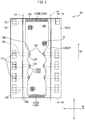
FIG. 2] FIG. 2 is a planar view of a pattern plate of the apparatus to manufacture the absorbent body of the absorbent article, according to the first embodiment. - [
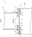
FIG. 3] FIG. 3 is a sectional view taken along line III-III ofFIG. 1 . - [
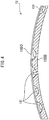
FIG. 4] FIG. 4 is a sectional view taken along line IV-IV ofFIG. 2 . - [
FIG. 5] FIG. 5 is a schematic sectional view of an apparatus to manufacture an absorbent body of an absorbent article, according to a second embodiment of the present invention. - [
FIG. 6] FIG. 6 is a schematic sectional view of an apparatus to manufacture an absorbent body of an absorbent article, according to a third embodiment of the present invention. - [
FIG. 7] FIG. 7 is a schematic sectional view of an apparatus to manufacture an absorbent body of an absorbent article, according to a fourth embodiment of the present invention. - The present invention is described in detail with reference to the above mentioned drawings. Incidentally, it should be noted that these drawings may not be depicted in the same size, scale, shape as those of the actual configuration elements, in order to facilitate understanding of the present invention and to simplify the description of the drawings.
- Hereinbelow, the apparatus to manufacture an absorbent body of an absorbent article according to the first embodiment of the present invention is described with reference to
FIGS. 1-4 . Theapparatus 1 according to the first embodiment includes a freelyrotatable suction drum 11, and asupply device 21 that includes acover duct 23 which is a part of thecircumferential surface 11S of thesuction drum 11 and, in the first embodiment, covers the upper portion of thecircumferential surface 11S. Theapparatus 1 according to the first embodiment further includes an absorbentbody conveying mechanism 31 which conveys the formed absorbent body A to a downstream process. - In the first embodiment, as shown in
FIGS. 1 and2 , thesuction drum 11 includes, in the circumferential surface, a plurality ofpattern plates 13 in each of which apattern hole 13H is formed, and amolding portion 15 formed in each of the pattern holes 13H. A rotation driving device (which is not shown), such as a servo motor, and the like, is connected to a shaft portion of thesuction drum 11, so that thesuction drum 11 can be rotationally driven at a desired peripheral speed. - As shown in
FIG. 4 , thepattern plate 13 is a metal plate which is curved with the curvature of thecircumferential surface 11S of thesuction drum 11 so as to form thecircumferential surface 11S of thesuction drum 11, and has a certain thickness. Thepattern hole 13H of thepattern plate 13 has a planar shape that is complementary to the outer shape of the absorbent body A to be manufactured, and penetrates through in a thickness direction. In the first embodiment, thepattern plate 13 is attached to aflange portion 11F which extends inward in the width direction of thesuction drum 11 from the internal surface of the side wall 11SW of thesuction drum 11, by a publicly known fastening means (which is not shown), such as bolts, and the like. - The
molding portion 15 which is formed in thepattern hole 13H of thepattern plate 13 forms the absorbent body A by accumulating the material of the absorbent body thereon, and in the first embodiment, is formed by a metal mesh (a net). Incidentally, inFIG. 2 , only a part of the mesh is shown in themolding portion 15 for the sake of clarity of the drawing, however, themolding portion 15 is formed entirely in thepattern hole 13H. - Further, an air discharging device (which is not shown) for discharging the air inside the
suction drum 11, such as a blower, a vacuum pump, and the like, is connected to thesuction drum 11, and by operating the air discharging device, the inside of thesuction drum 11 is made to have a negative pressure. Accordingly, in the first embodiment, thecircumferential surface 11S of thesuction drum 11 is configured to suck the air toward the inside of thesuction drum 11 from the internal space S of thecover duct 23, through thepattern hole 13H of thepattern plate 13, in the circumferential direction region RZ which is covered by thecover duct 23. Further, as shown inFIG. 3 , thecircumferential surface 11S of thesuction drum 11 and thelower end 23E of thecover duct 23 are close to each other, and the abuttingmember 27 which is, for example, a metal brush, felt, and the like, is provided at thelower end 23E of thecover duct 23, and is arranged so as to extend toward thecircumferential surface 11S of thesuction drum 11 and have the tip thereof abut against thecircumferential surface 11S of thesuction drum 11. Accordingly, a constant airtightness of the internal space S of thecover duct 23 is ensured. As a result, in the first embodiment, by the suction action by the air discharging device of thesuction drum 11, the internal space S of thecover duct 23 can be made to have negative pressure, and the supplied material of the absorbent body can be sucked against themolding portion 15 and be accumulated thereon. Incidentally, in the present description, "an internal space of a cover duct" means the space defined by thecircumferential surface 11S of thesuction drum 11, which is defined by thepattern plate 13 and themolding portion 15, and by the internal wall surface of thecover duct 23. - In the
apparatus 1 according to the first embodiment, fibers and super absorbent polymers (SAP) which are the material of the absorbent body are supplied to thecircumferential surface 11S of thesuction drum 11, and especially to themolding portion 15, in the circumferential direction region RZ which is covered by thecover duct 23, through thecover duct 23. The fibers are supplied in an amount corresponding to the basis weight of the absorbent body A to be manufactured, in a state of being opened by an opening device (which is not shown), such as a carding machine, and the like, placed in the upstream of the cover duct 23 (upper direction inFIG. 1 ). Further, a predetermined amount of the super absorbent polymer material is supplied to the inside of thecover duct 23 from the super absorbent polymermaterial supplying portion 25 which is opened inside thecover duct 23. - Further, in the first embodiment, in the
pattern plate 13, a plurality of air jetting ports 13O in the external surface 13SO of thepattern plate 13 which forms thecircumferential surface 11S of thesuction drum 11, and anair intake port 131 which is connected to each of the air jetting ports 13O through theair vent passage 13C are provided. As shown inFIG. 3 , each of the air jetting ports 13O faces outward in the radial direction of thesuction drum 11, and is capable of jetting out the air in the radial direction of thesuction drum 11. On the other hand, the each of theair intake ports 131 is released to the atmosphere. Further, in the first embodiment, each of theair vent passages 13C extends at a substantially constant position in the thickness direction of thepattern plate 13, and is formed such that there is no seam therethrough, i.e., the cross sectional area thereof does not radically enlarge or radically shrink. - In the first embodiment, each of the
air intake ports 13I is provided at the end portions of thepattern plate 13 in the width direction W. Further, as shown inFIG. 2 , the air jetting ports 13O include a plurality of external surface air jetting ports 13OS which are provided at positions adjacent to thepattern hole 13H in the width direction W, and border air jetting ports 13OB which are provided at positions adjacent to thepattern hole 13H in the longitudinal direction L, at both of the longitudinal direction end portions 13EL of thepattern hole 13H. To be more specific, each of the external surface air jetting ports 13OS is provided at the protrudedportion 13P which protrudes with respect to thepattern hole 13H toward the center in the width direction W of thepattern plate 13. Each of the border air jetting ports 13OB is provided across the substantially whole length of the end portion along the end portion in the longitudinal direction L of thepattern plate 13H. Incidentally,FIG. 2 seems to describe a number of small holes as the border air jetting ports 13OB, however, these are actually partially blocking the holes to suppress the fibers from entering the border air jetting ports 13OB. Accordingly, in the first embodiment, one border air jetting port 13OB is provided for each of the both longitudinal direction end portions 13EL of thepattern plate 13. - The absorbent
body conveying mechanism 31 receives the absorbent body A formed in themolding portion 15 from thesuction drum 11, and conveys the absorbent body A to the downstream process. In the first embodiment, the absorbentbody conveying mechanism 31 includes a carriersheet feeding portion 35 for feeding out acarrier sheet 33 which may be a nonwoven fabric, and the like, in the conveying direction MD, and a conveying device (which is not shown), such as a belt conveyer for conveying thefed carrier sheet 33 in the conveying direction MD, and the like. Incidentally, thesuction drum 11 may include a mechanism that blows air to themolding portion 15 from inside of thesuction drum 11, so as to extract the absorbent body A from thepattern hole 13H, when delivering the absorbent body A from thesuction drum 11 to thecarrier sheet 33. - Hereinbelow, the operation and the effect of the
apparatus 1 according to the first embodiment are described. -
- (1) In the first embodiment, in the
pattern plate 13, the protrudedportions 13P which protrude toward thepattern hole 13H in the center in the width direction W of thepattern plate 13 are formed, so as to form the absorbent body A into a desired shape. Since these protrudedportions 13P are protruded with respect to thepattern hole 13H, when the external surface air jetting ports 13OS are not provided, it is easier for the material of the absorbent body to be accumulated thereon compared to other portions of the external surface 13SO of thepattern plate 13. Then, the material of the absorbent body accumulated on these protrudedportions 13P may form the absorbent body A together with the material of the absorbent body accumulated on themolding portion 15, whereby the absorbent body A may not be formed into a desired shape outlined by thepattern hole 13H. In order to suppress such situation, in the first embodiment, the external surface air jetting ports 13OS are provided in the protrudedportions 13P, as described above. Accordingly, air is jetted out from the external surface air jetting ports 13OS, so as to blow off the material of the absorbent body, whereby the accumulation of the material of the absorbent body on the protrudedportions 13P can be prevented, and the absorbent body A can be formed only by the material of the absorbent body accumulated on themolding portion 15. As a result, the absorbent body A having the desired shape can be formed by theapparatus 1 according to the first embodiment. - (2) Further, in the first embodiment, the front edges 13PL and the rear edges 13PT of the protruded
portion 13P extending in a direction inclined with respect to the rotation direction RD of thesuction drum 11, as formed by the protrudedportion 13P are formed. When the external surface air jetting ports 13OS are not provided, since thepattern plate 13 moves while rotating as thesuction drum 11 rotates, the material of the absorbent body is supplied in a concentrated manner to the portions of themolding portion 15 in the vicinity of the front edges 13PL of the protrudedportion 13P, and on the contrary, only a little amount of the material of the absorbent body is supplied to the portions of themolding portion 15 in the vicinity of the rear edges 13PT of the protrudedportion 13P, due to the shape of the protrudedportions 13P. As a result, the basis weight of the absorbent body A may be uneven from portions to portions, whereby there may be cases where the function of the absorbent body A cannot be demonstrated in the desired manner. In order to suppress such situation, in the first embodiment, the external surface air jetting ports 13OS are provided in the protrudedportions 13P, as described above. Accordingly, by temporarily blowing off the material of the absorbent body supplied to themolding portion 15, in the front edges 13PL side and in the vicinity of the rear edges 13PT, the supply distribution of the material of the absorbent body can be changed intentionally. As a result, the absorbent body A having the desired basis weight distribution even in the front edges 13PL side and in the vicinity of the rear edges 13PT can be manufactured. - (3) In the
apparatus 1 according to the first embodiment, one absorbent body A is manufactured per onepattern plate 13, and each of the absorbent bodies A is formed as a separate body. Accordingly, in the longitudinal direction end portions 13EL of thepattern plate 13, not thepattern hole 13H but the external surface 13SO of thepattern plate 13 is formed. Consequently, when the border air jetting ports 13OB as described above are not provided, since the center portion in the width direction W in the longitudinal direction end portions 13EL of thepattern plate 13 is located at the portion extended in the longitudinal direction L of thepattern plate 13 from themolding portion 15, it is easier for the material of the absorbent body to be accumulated thereon compared to other portions of the external surface 13SO of thepattern plate 13. As a result, there may be cases where the outer shape at the longitudinal direction end portions of the absorbent body A is not formed in the desired manner, and in extreme cases, two absorbent bodies A may be connected to each other. In order to suppress such situation, in the first embodiment, the border air jetting ports 13OB are provided at the longitudinal direction end portions 13EL of thepattern plate 13, as described above, whereby the material of the absorbent body can be suppressed from being accumulated at the longitudinal direction end portions 13EL of thepattern plate 13. As a result, the absorbent body A having the desired outer shape at the longitudinal direction end portion of the absorbent body A can be formed. - (4) In the first embodiment, as described above, the internal space S of the
cover duct 23 is made to have a negative pressure by the suction of the air discharging device (which is not shown) connected to thesuction drum 11, and the air jetting ports 13O are connected to theair intake ports 13I which are released to the atmosphere, through theair vent passages 13C. Accordingly, the air can be supplied to the internal space S of thecover duct 23 from the atmosphere, by the pressure differential between the internal space S of thecover duct 23 and the atmosphere, without using additional power. As a result, theapparatus 1 can be simplified, in addition to being able to reduce the manufacturing cost of the absorbent body A. Incidentally, in theapparatus 1 according to the first embodiment, since the air is jetted out from the air jetting ports 13O in accordance with the mechanism as described above, the air jetting mechanism is configured by the air discharging device (which is not shown) connected to thesuction drum 11, theair intake ports 13I, theair vent passages 13C, and the air jetting ports 13O. - (5) In the first embodiment, each of the
air vent passages 13C extends at the substantially constant position in the thickness direction of thepattern plate 13, and is formed such that there is no seam therethrough, and the cross sectional area thereof does not radically enlarge or radically shrink, as described above. Each of theair vent passages 13C extends at the substantially constant position in the thickness direction of thepattern plate 13, whereby each of theair vent passages 13C has substantially no variation in the thickness direction of thepattern plate 13 inside thepattern plate 13. As a result, thepattern plate 13 can be thinly formed, whereby the manufacturing time and the manufacturing cost of thepattern plate 13 can be reduced. Further, each of theair vent passages 13C has no seam therethrough, whereby radical enlargement and radical shrinkage of the cross section area of each of theair vent passages 13C are not generated, and the pressure loss of the air passing through theair vent passages 13C can be suppressed, and hence the decrease in the energy efficiency of the air jetted out from the air jetting ports 13O can be suppressed. - In the first embodiment, the external surface air jetting ports 13OS are provided in the protruded
portions 13P, however, the external surface air jetting ports 13OS may be provided in other portions. In other words, the external surface air jetting ports 13OS may be provided at any portions of the internal space facing portion 13SOF which faces the internal space S of thecover duct 23, among the external surface 13SO of thepattern plate 13. Incidentally, is should be noted that the internal space facing portion 13SOF refers to the portion of the external surface 13SO of thepattern plate 13 which intermittently faces the internal space S of thecover duct 23, as thesuction drum 11 moves while rotating, and does not always face the internal space S of thecover duct 23. More specifically, in the first embodiment, the internal space facing portion 13SOF refers to the region between the contact lines LA which are the locus of the portions at which the tip of the abuttingmember 27 of thelower end 23E of thecover duct 23 abuts against the external surface 13SO of thepattern plate 13. - In the first embodiment, as shown in
FIG. 2 , each of the external surface air jetting ports 13OS are connected to oneair intake port 131, each of the border air jetting ports 13OB is connected to the twoair intake ports 13I positioned at both sides in the width direction W, and the air jetting ports 13O are not connected to each other. However, the present invention is not limited to this embodiment. For example, twoair vent passages 13C may be connected to each other, whereby two air jetting ports 13O may be connected to each other. However, the air jetting ports 13O are preferably not connected to each other, as described in the first embodiment. To be more specific, one air jetting port 13O is preferably not connected to another air jetting port 13O whose starting period and ending period of facing the internal space S of thecover duct 23, do not coincide with a starting period and an ending period of facing the internal space S of thecover duct 23 of the one air jetting port 13O, respectively. On the other hand, when one air jetting port 13O is connected to another air jetting port 13O whose starting period and ending period of facing the internal space S of thecover duct 23, do not coincide with a starting period and an ending period of facing the internal space S of thecover duct 23 of the one air jetting port 13O, respectively, a moment at which the one air jetting port 13O faces the internal space S of thecover duct 23 and the another air jetting port 13O does not face the internal space S of thecover duct 23, i.e., the another air jetting port 13O is released to the atmosphere is present. At this moment, the another air jetting port 13O is to function as the air intake port of the one air jetting port 13O. Then, the wind pressure and the wind speed of the air jetted out from the one air jetting port 13O when the another air jetting port 13O faces the internal space S of thecover duct 23 differ from those when the another air jetting port 13O does not face the internal space S of thecover duct 23. On the other hand, when one air jetting port 13O is not connected to another air jetting port 13O whose starting period and ending period of facing the internal space S of thecover duct 23, do not coincide with a starting period and an ending period of facing the internal space S of thecover duct 23 of the one air jetting port 13O, respectively, as mentioned above, the air with a constant wind pressure and wind speed can always be blown from the one air jetting port 13O, when the one air jetting port 13O faces the internal space S of thecover duct 23. As a result, the absorbent body A of an absorbent article having the desired outer shape and basis weight distribution can be stably manufactured. - Incidentally, in the first embodiment, the opening cross section of the
cover duct 23 which opens to thecircumferential surface 11S of thesuction drum 11 is substantially rectangular. Accordingly, in order for the two air jetting ports 13O to have starting periods and ending periods of facing the internal space S of thecover duct 23 that coincide with each other, the positions in the width direction W of the air jetting ports 13O should match. Accordingly, in the first embodiment, two air jetting ports 13O, the positions of which in the longitudinal direction L of thepattern plate 13 are different from each other, are preferably not connected to each other. - In the first embodiment, one external surface air jetting port 13OS is provided for each of the protruded
portions 13P, however, the present invention is not limited to this embodiment. In the present invention, in order to prevent the material of the absorbent body from being accumulated on the external surface 13SO of thepattern plate 13, or to obtain the desired supply distribution of the material of the absorbent body, the shape, the number, the position of the external surface air jetting ports 13OS, and the wind pressure and wind speed of the air jetted out from the external surface air jetting ports 13OS, may be determined by, for example, an experiment, and the like. For example, in another embodiment, in each of the protrudedportions 13P, a plurality of air jetting ports which are smaller than the external surface air jetting ports 13OS are provided along the front edges 13PL side and the rear edges 13PT of the protrudedportions 13P. Further, in still another embodiment, an elongated air jetting port is provided along the front edges 13PL and the rear edges 13PT of the protrudedportions 13P, in thepattern plate 13. - Further, in the first embodiment, the air jetting port 13O faces outward in the radial direction of the
suction drum 11, and jets out the air in the radial direction of thesuction drum 11. However, in the present invention, in order to obtain the absorbent body A having the desired outer shape and basis weight distribution, the air jetting port 13O may be formed so that the air jetting port 13O faces in any direction and jets out the air therefrom. - In the first embodiment, the
molding portion 15 is flat, however, themolding portion 15 may have protrusions and depressions in the thickness direction. Further, themolding portion 15 is a metal mesh, however, in the present invention, the molding portion may not be metallic, and may alternatively be a plate having a plurality of small holes. - Hereinbelow, with reference to
FIG. 5 which corresponds toFIG. 3 , the apparatus to manufacture an absorbent body of an absorbent article according to the second embodiment of the present invention will be described. In the second embodiment, the differences from the first embodiment will be mainly described. Further, it should be noted that the configurations in the first embodiment other than those different from the second embodiment are applicable to the second embodiment, and that a person skilled in the art can arbitrarily combine these configurations within obvious ranges. - In the second embodiment, in the
pattern plate 13, theair vent passage 13C which connects the external surface air jetting port 13OS and theair intake port 13I is branched off, and the internal surface air jetting port 13OI which is the air jetting port 13O being opened from the internal surface 13SI that defines thepattern hole 13H is formed. - By being formed with the internal surface air jetting port 13OI, the air can be blown to the material of the absorbent body which is accumulated on the
molding portion 15, from the side. According to this configuration, an extremely thin air layer such as the one which is generated on an air hockey stand installed in an amusement center, and the like can be formed in between the internal surface 13SI of thepattern plate 13 and the material of the absorbent body accumulated on themolding portion 15. Accordingly, the material of the absorbent body accumulated on themolding portion 15 is isolated from the external surface 13SO of thepattern plate 13, whereby forming the absorbent body A together with the material of the absorbent body accumulated outside thepattern hole 13H can be suppressed. As a result, the absorbent body A having an outer shape along the outline shape of thepattern hole 13H can be formed. Further, when extracting the absorbent body A from themolding portion 15, the friction between the side portion of the absorbent body A and the internal surface SI of thepattern plate 13 can be reduced, whereby the extraction of the absorbent body A from themolding portion 15 becomes easier. - In the second embodiment, the
air vent passage 13C which is connected to oneair intake port 13I is branched off, and the air supplied form theair intake port 13I jets out from both the internal surface air jetting port 13OI and the external surface air jetting port 13OS, however, the present invention is not limited to such configuration. For example, in an apparatus according to another embodiment, the external surface air jetting port 13OS is not provided, and only the internal surface air jetting port 13OI is provided, and oneair intake port 13I is provided for one internal surface air jetting port 13OI. Further, in still another embodiment, separateair intake port 13I andair vent passage 13C are provided to supply air to the internal surface air jetting port 13OI and the external surface air jetting port 13OS, and the air is supplied to the internal surface air jetting port 13OI and the external surface air jetting port 13OS from each of theair intake ports 131 through each of theair vent passages 13C. - Hereinbelow, with reference to
FIG. 6 which corresponds toFIG. 3 , the apparatus to manufacture an absorbent body of an absorbent article according to the third embodiment of the present invention will be described. In the third embodiment, the differences from the first embodiment will be mainly described. Further, it should be noted that the configurations in the first embodiment other than those different from the third embodiment are applicable to the third embodiment, and that a person skilled in the art can arbitrarily combine these configurations within obvious ranges. - In the third embodiment, the extended portion 13EX, which protrudes inwardly in the radial direction of the
suction drum 11 from the back surface 13SB, i.e., opposite to the external surface 13SO of thepattern plate 13, and extends to the position which faces the back surface 15SB, i.e., in the opposite side from the side at which the material of the absorbent body is accumulated in themolding portion 15, is additionally formed for thepattern plate 13. At the tip portion of the extended portion 13EX, the molding portion air jetting port 13OF is provided in order to blow air toward the back surface 15SB of themolding portion 15, and to blow the air to the internal space S of thecover duct 23 from themolding portion 15. - As shown in
FIG. 6 , theair vent passage 13C which connects the external surface air jetting port 13OS and theair intake port 13I is branched off, and theair intake port 13I and the molding portion air jetting port 13OF are connected to each other, whereby the air inhaled from theair intake port 13I can be jetted out from the molding portion air jetting port 13OF. - In the third embodiment, the air is jetted out toward the internal space S of the
cover duct 23 through themolding portion 15 from the molding portion air jetting port 13OF, whereby the material of the absorbent body accumulated on themolding portion 15 can be blown off and the accumulation amount thereof can be reduced, at the portion where the air is blown. As a result, the absorbent body A having the desired basis weight can be manufactured. Alternatively, the air can be blown to the portions of the absorbent body A where the basis weight thereof is unintentionally increased in theapparatus 1 according to the first embodiment, from the molding portion air jetting port 13OF, and the basis weight thereof can be equalized with that of the other portions, whereby the absorbent body A having an equalized basis weight distribution can be manufactured. - In
FIG. 6 , two extended portions 13EX and two molding portion air jetting ports 13OF are described, however, the present invention is not limited to this embodiment. For example, the number of the extended portions 13EX and the molding portion air jetting ports 13OF, and the portion to which the air is blown from the molding portion air jetting ports 13OF can be arbitrarily set. Further, the shape of the extended portion 13EX can be arbitrarily determined as long as the molding portion air jetting port 13OF can be disposed as desired and the accumulation of the material of the absorbent body in themolding portion 15 is not inhibited. - In the third embodiment, the extended portion 13EX is provided in the
pattern plate 13, and the molding portion air jetting port 13OF is provided at the tip thereof, however, the present invention is not limited to this embodiment, as long as a mechanism in order to blow the air to the internal space S of thecover duct 23 from themolding portion 15 is provided. For example, the side wall 11SW of thesuction drum 11 may be provided with a penetrated hole, a hose which a nozzle is attached at the tip thereof may be connected to the penetrated hole, and the nozzle opening may be fixed facing toward themolding portion 15 so that the nozzle can move while rotating as thesuction drum 11 rotates, whereby the air may be blown from the nozzle opening. In this configuration, the nozzle opening corresponds to the molding portion air jetting port 13OF in the third embodiment. - Hereinbelow, with reference to
FIG. 7 which corresponds toFIG. 3 , the apparatus to manufacture an absorbent body of an absorbent article according to the fourth embodiment of the present invention will be described. In the fourth embodiment, the differences from the first embodiment will be mainly described. Further, it should be noted that the configurations in the first embodiment other than those different from the fourth embodiment are applicable to the fourth embodiment, and that a person skilled in the art can arbitrarily combine these configurations within obvious ranges. - The
air supplying mechanism 41 which supplies compressed air from theair intake port 131 toward theair jetting port 130 is provided in theapparatus 1 according to the fourth embodiment. As shown inFIG. 7 , theair supplying mechanism 41 is configured by including theair supplying cover 43 which covers theair intake port 13I, and thecompressor 47 which supplies the compressed air to the inside of theair supplying cover 43 through theduct 45. - The
air supplying cover 43 is hermetically sealed with respect to the outside to some extent, so that the compressed air supplied from thecompressor 47 can flow into theair intake port 13I efficiently, whereby a constant airtightness of the inside of theair supplying cover 43 is ensured. In order to ensure the constant airtightness of the inside of theair supplying cover 43, an abutting member which abuts the external surface 13SO of thepattern plate 13 may be provided at the lower end of theair supplying cover 43, in the same manner as thecover duct 23. - According to this configuration, the compressed air with desired wind pressure and wind speed can be blown from the air jetting port 13O. As a result, an absorbent body of an absorbent article having a desired outer shape and basis weight distribution can be manufactured.
- Further, the
air supplying mechanism 41 preferably supplies the compressed air only to theair intake port 13I which is connected to the air jetting port 13O that faces the internal space S of thecover duct 23, among theair intake ports 13I. To be more specific, in the case of the fourth embodiment, theair supplying cover 43 preferably covers theair intake port 13I in the above described circumferential direction region RZ, by the approximately same range as thecover duct 23 covers thecircumferential surface 11S of thesuction drum 11 in the rotation direction RD of thesuction drum 11. According to this configuration, the apparatus can be configured so that the air is jetted out only from the air jetting port 13O facing the internal space S of thecover duct 23, and the air is not jetted out from the air jetting port 13O which does not face the internal space S of thecover duct 23. As a result, the compressed air can be supplied only to the air jetting port 13O which is required to jet out air, and the manufacturing cost of the absorbent body A can be reduced. - In the above-described embodiment, the
pattern plate 13 is made of a metal, and more specifically, thepattern plate 13 is formed by a plurality of metal plates being laminated and then sintered and joined so as to be integrated. However, in the present invention, the forming method of thepattern plate 13 is not limited to this, and any manufacturing method thereof can be used. For example, in another embodiment, the pattern plate is made of photocurable resin and is formed by a 3D printer. - Incidentally, all the features which can be understood by those skilled in the art from the description of the specification, drawings and the claims can be applied independently or can be applied in optional combination with another one or a plurality of features disclosed herein to be bound together, as long as such features are explicitly excluded or its technical aspect becomes an impossible or a meaningless combination, even when such features are described only in combination with another specific feature in this specification.
- For example, an apparatus according to another embodiment includes the
suction drum 11 in the circumferential surface, which includes thepattern plate 13 in which both of the internal surface air jetting port 13OI that is shown in the second embodiment and the molding portion air jetting port 13OF that is shown in the third embodiment are provided. - Further, the
air supplying mechanism 41 which supplies the compressed air toward the air jetting port 13O from theair intake port 13I, that is shown in the fourth embodiment may be provided in theapparatus 1 according to the second and the third embodiments. -
- 1
- apparatus (to manufacture an absorbent body of an absorbent article)
- 11
- suction drum
- 11S
- circumferential surface
- 13
- pattern plate
- 13C
- air vent passage (air jetting mechanism)
- 13H
- pattern hole
- 13I
- air intake port (air jetting mechanism)
- 13O
- air jetting port (air jetting mechanism)
- 13SO
- external surface
- 15
- molding portion
- 21
- supply device
- 23
- cover duct
- 41
- air supplying mechanism
- A
- absorbent body
- S
- internal space (of a cover duct)
Claims (8)
- An apparatus to manufacture an absorbent body of an absorbent article, the apparatus comprising:a freely rotatable suction drum which includes, in a circumferential surface, a pattern plate which has a shape that is complementary to an outer shape of the absorbent body and in which a pattern hole that penetrates through in a thickness direction is formed, and a molding portion formed inside the pattern hole of the pattern plate, which forms the absorbent body by accumulating a material of the absorbent body; anda supply device which includes a cover duct that covers a part of the circumferential surface of the suction drum, and which supplies the material of the absorbent body to the molding portion through the cover duct, whereinthe apparatus is provided with an air jetting mechanism which includes an air jetting port, and the air jetting port moves while rotating as the suction drum rotates and jets out air toward an internal space of the cover duct, from both of or either one of the pattern plate and the molding portion.
- The apparatus according to claim 1, wherein the pattern plate includes an internal space facing portion which faces the internal space of the cover duct, in an external surface of the pattern plate which faces outward in a radial direction of the suction drum, and
the air jetting port is provided in the internal space facing portion. - The apparatus according to claim 1 or 2, wherein the air jetting port is provided in an internal surface of the pattern plate which defines the pattern hole.
- The apparatus according to any one of claims 1 to 3, wherein the air jetting mechanism jets out the air toward the internal space of the cover duct through the molding portion.
- The apparatus according to any one of claims 1 to 4, wherein the internal space of the cover duct is made to have a negative pressure by a suction of the suction drum, and
the air jetting mechanism further includes an air intake port which is connected to the air jetting port and is released to an atmosphere. - The apparatus according to claim 5, wherein a plurality of the air jetting ports are provided, and
one of the air jetting ports is not connected to another air jetting port, whose starting period and an ending period of facing the internal space of the cover duct, do not coincide with a starting period and an ending period of facing the internal space of the cover duct of the one of the air jetting ports, respectively. - The apparatus according to any one of claims 1 to 4, wherein the air jetting mechanism includes an air supplying mechanism which supplies compressed air from an air intake port which is connected to the air jetting port toward the air jetting port.
- The apparatus according to claim 7, wherein a plurality of the air intake ports are provided, and
the air supplying mechanism supplies the compressed air only to an air intake port which is connected to the air jetting port that faces the internal space of the cover duct, among the air intake ports.
Applications Claiming Priority (1)
| Application Number | Priority Date | Filing Date | Title |
|---|---|---|---|
| PCT/JP2015/068560 WO2016208076A1 (en) | 2015-06-26 | 2015-06-26 | Apparatus for manufacturing absorbent for absorbent article |
Publications (3)
| Publication Number | Publication Date |
|---|---|
| EP3275412A1 true EP3275412A1 (en) | 2018-01-31 |
| EP3275412A4 EP3275412A4 (en) | 2018-04-18 |
| EP3275412B1 EP3275412B1 (en) | 2019-11-20 |
Family
ID=55808313
Family Applications (1)
| Application Number | Title | Priority Date | Filing Date |
|---|---|---|---|
| EP15896394.2A Active EP3275412B1 (en) | 2015-06-26 | 2015-06-26 | Apparatus for manufacturing absorbent for absorbent article |
Country Status (4)
| Country | Link |
|---|---|
| EP (1) | EP3275412B1 (en) |
| JP (1) | JP5913757B1 (en) |
| CN (1) | CN107708626B (en) |
| WO (1) | WO2016208076A1 (en) |
Families Citing this family (3)
| Publication number | Priority date | Publication date | Assignee | Title |
|---|---|---|---|---|
| CN106236386A (en) * | 2016-08-29 | 2016-12-21 | 谢泽波 | The forming method of sanitary towel's liquid permeability surface layer |
| KR102359940B1 (en) * | 2017-07-28 | 2022-02-07 | 현대자동차 주식회사 | Intercooler and engine including the same |
| JP7519310B2 (en) | 2021-02-03 | 2024-07-19 | ニチダイフィルタ株式会社 | Pattern Plate |
Family Cites Families (11)
| Publication number | Priority date | Publication date | Assignee | Title |
|---|---|---|---|---|
| JPH0775664B2 (en) * | 1987-04-30 | 1995-08-16 | 新田ゼラチン株式会社 | Powder and granular material feeder |
| DE602004026566D1 (en) * | 2004-07-28 | 2010-05-27 | Procter & Gamble | Indirect pressure from AMG |
| US7524449B2 (en) * | 2005-08-17 | 2009-04-28 | The Procter & Gamble Company | Method and apparatus for forming a batt of particulate material for use as a component in an absorbent core assembly |
| JP5210565B2 (en) * | 2007-07-30 | 2013-06-12 | ユニ・チャーム株式会社 | Absorbent articles |
| JP5271629B2 (en) * | 2008-08-01 | 2013-08-21 | 花王株式会社 | Absorbent manufacturing method and manufacturing apparatus |
| KR20100033209A (en) * | 2008-09-19 | 2010-03-29 | 유한킴벌리 주식회사 | Method for manufacturing unwooven web perforated without phisical or thermal deformation and absorbent articles comprising the unwooven web |
| JP5433271B2 (en) * | 2009-03-24 | 2014-03-05 | ユニ・チャーム株式会社 | Absorber manufacturing apparatus and manufacturing method |
| US7906065B1 (en) * | 2009-08-18 | 2011-03-15 | The Procter & Gamble Company | Method and apparatus for forming a batt of particulate material for use as a component in an absorbent core assembly |
| CN103402470B (en) * | 2011-02-10 | 2016-10-05 | 株式会社瑞光 | Method and device for disposing granular bodies |
| JP5856832B2 (en) * | 2011-12-14 | 2016-02-10 | 花王株式会社 | Absorber manufacturing equipment |
| CN204192879U (en) * | 2014-08-15 | 2015-03-11 | 中天(中国)工业有限公司 | A kind of absorbent cores shaped device |
-
2015
- 2015-06-26 WO PCT/JP2015/068560 patent/WO2016208076A1/en not_active Ceased
- 2015-06-26 CN CN201580081119.9A patent/CN107708626B/en active Active
- 2015-06-26 JP JP2015556317A patent/JP5913757B1/en active Active
- 2015-06-26 EP EP15896394.2A patent/EP3275412B1/en active Active
Also Published As
| Publication number | Publication date |
|---|---|
| JP5913757B1 (en) | 2016-04-27 |
| EP3275412B1 (en) | 2019-11-20 |
| WO2016208076A1 (en) | 2016-12-29 |
| JPWO2016208076A1 (en) | 2017-06-22 |
| CN107708626A (en) | 2018-02-16 |
| CN107708626B (en) | 2021-03-09 |
| EP3275412A4 (en) | 2018-04-18 |
Similar Documents
| Publication | Publication Date | Title |
|---|---|---|
| EP3275412B1 (en) | Apparatus for manufacturing absorbent for absorbent article | |
| US4893741A (en) | Air guide box for stabilizing the path of a paper web | |
| US6273417B1 (en) | Delivery for sheet processing printing machine | |
| JP4677034B2 (en) | Drying equipment | |
| US7942096B2 (en) | Method of controlling a powder sprayer and printing press having a powder sprayer | |
| EP1793943B1 (en) | Dust removal apparatus and method | |
| CN101108703A (en) | Device for conveying a stream of sheets stacked one above the other in scales | |
| CN104204316B (en) | Suction nozzle of carding machine | |
| KR102163409B1 (en) | Suction roll system | |
| CN116277685A (en) | Device and method for generating negative pressure in film machine | |
| US5860223A (en) | Device for drying a web | |
| JP2002173834A (en) | Equipment provided on the card | |
| JP2021031021A (en) | Cross-flow fan, lift generator with it and aircraft with it | |
| US11415100B2 (en) | Rotor blade for a wind turbine and wind turbine | |
| JP5892883B2 (en) | Absorber manufacturing equipment | |
| JPH0281870A (en) | Device for guiding printing book fraction in folder of rotary press | |
| KR20160033647A (en) | Liquid application device and liquid application method | |
| JPH11138752A (en) | Sheet guide device for sheet-fed printing press | |
| JP6259620B2 (en) | Absorber manufacturing equipment | |
| JP3653481B2 (en) | Inter folder | |
| JP2015019935A (en) | Liquid application apparatus and liquid application method | |
| JP4184828B2 (en) | Sheet paper processing rotary printing press equipped with a flattening device | |
| JP2009519095A (en) | Method and apparatus for applying particles to absorbent tissue | |
| JP2014040807A (en) | Propeller fan | |
| JP2025172554A (en) | Water flow charging device |
Legal Events
| Date | Code | Title | Description |
|---|---|---|---|
| STAA | Information on the status of an ep patent application or granted ep patent |
Free format text: STATUS: THE INTERNATIONAL PUBLICATION HAS BEEN MADE |
|
| PUAI | Public reference made under article 153(3) epc to a published international application that has entered the european phase |
Free format text: ORIGINAL CODE: 0009012 |
|
| STAA | Information on the status of an ep patent application or granted ep patent |
Free format text: STATUS: REQUEST FOR EXAMINATION WAS MADE |
|
| 17P | Request for examination filed |
Effective date: 20171026 |
|
| AK | Designated contracting states |
Kind code of ref document: A1 Designated state(s): AL AT BE BG CH CY CZ DE DK EE ES FI FR GB GR HR HU IE IS IT LI LT LU LV MC MK MT NL NO PL PT RO RS SE SI SK SM TR |
|
| AX | Request for extension of the european patent |
Extension state: BA ME |
|
| A4 | Supplementary search report drawn up and despatched |
Effective date: 20180316 |
|
| RIC1 | Information provided on ipc code assigned before grant |
Ipc: A61F 13/49 20060101ALI20180312BHEP Ipc: A61F 13/15 20060101AFI20180312BHEP |
|
| DAV | Request for validation of the european patent (deleted) | ||
| DAX | Request for extension of the european patent (deleted) | ||
| STAA | Information on the status of an ep patent application or granted ep patent |
Free format text: STATUS: EXAMINATION IS IN PROGRESS |
|
| 17Q | First examination report despatched |
Effective date: 20181114 |
|
| GRAP | Despatch of communication of intention to grant a patent |
Free format text: ORIGINAL CODE: EPIDOSNIGR1 |
|
| STAA | Information on the status of an ep patent application or granted ep patent |
Free format text: STATUS: GRANT OF PATENT IS INTENDED |
|
| INTG | Intention to grant announced |
Effective date: 20190724 |
|
| GRAS | Grant fee paid |
Free format text: ORIGINAL CODE: EPIDOSNIGR3 |
|
| GRAA | (expected) grant |
Free format text: ORIGINAL CODE: 0009210 |
|
| STAA | Information on the status of an ep patent application or granted ep patent |
Free format text: STATUS: THE PATENT HAS BEEN GRANTED |
|
| AK | Designated contracting states |
Kind code of ref document: B1 Designated state(s): AL AT BE BG CH CY CZ DE DK EE ES FI FR GB GR HR HU IE IS IT LI LT LU LV MC MK MT NL NO PL PT RO RS SE SI SK SM TR |
|
| REG | Reference to a national code |
Ref country code: GB Ref legal event code: FG4D |
|
| REG | Reference to a national code |
Ref country code: CH Ref legal event code: EP |
|
| REG | Reference to a national code |
Ref country code: IE Ref legal event code: FG4D |
|
| REG | Reference to a national code |
Ref country code: DE Ref legal event code: R096 Ref document number: 602015042337 Country of ref document: DE |
|
| REG | Reference to a national code |
Ref country code: AT Ref legal event code: REF Ref document number: 1203339 Country of ref document: AT Kind code of ref document: T Effective date: 20191215 |
|
| REG | Reference to a national code |
Ref country code: SE Ref legal event code: TRGR |
|
| REG | Reference to a national code |
Ref country code: NL Ref legal event code: FP |
|
| REG | Reference to a national code |
Ref country code: LT Ref legal event code: MG4D |
|
| PG25 | Lapsed in a contracting state [announced via postgrant information from national office to epo] |
Ref country code: LT Free format text: LAPSE BECAUSE OF FAILURE TO SUBMIT A TRANSLATION OF THE DESCRIPTION OR TO PAY THE FEE WITHIN THE PRESCRIBED TIME-LIMIT Effective date: 20191120 Ref country code: GR Free format text: LAPSE BECAUSE OF FAILURE TO SUBMIT A TRANSLATION OF THE DESCRIPTION OR TO PAY THE FEE WITHIN THE PRESCRIBED TIME-LIMIT Effective date: 20200221 Ref country code: LV Free format text: LAPSE BECAUSE OF FAILURE TO SUBMIT A TRANSLATION OF THE DESCRIPTION OR TO PAY THE FEE WITHIN THE PRESCRIBED TIME-LIMIT Effective date: 20191120 Ref country code: NO Free format text: LAPSE BECAUSE OF FAILURE TO SUBMIT A TRANSLATION OF THE DESCRIPTION OR TO PAY THE FEE WITHIN THE PRESCRIBED TIME-LIMIT Effective date: 20200220 Ref country code: FI Free format text: LAPSE BECAUSE OF FAILURE TO SUBMIT A TRANSLATION OF THE DESCRIPTION OR TO PAY THE FEE WITHIN THE PRESCRIBED TIME-LIMIT Effective date: 20191120 Ref country code: BG Free format text: LAPSE BECAUSE OF FAILURE TO SUBMIT A TRANSLATION OF THE DESCRIPTION OR TO PAY THE FEE WITHIN THE PRESCRIBED TIME-LIMIT Effective date: 20200220 |
|
| PG25 | Lapsed in a contracting state [announced via postgrant information from national office to epo] |
Ref country code: RS Free format text: LAPSE BECAUSE OF FAILURE TO SUBMIT A TRANSLATION OF THE DESCRIPTION OR TO PAY THE FEE WITHIN THE PRESCRIBED TIME-LIMIT Effective date: 20191120 Ref country code: IS Free format text: LAPSE BECAUSE OF FAILURE TO SUBMIT A TRANSLATION OF THE DESCRIPTION OR TO PAY THE FEE WITHIN THE PRESCRIBED TIME-LIMIT Effective date: 20200320 Ref country code: HR Free format text: LAPSE BECAUSE OF FAILURE TO SUBMIT A TRANSLATION OF THE DESCRIPTION OR TO PAY THE FEE WITHIN THE PRESCRIBED TIME-LIMIT Effective date: 20191120 |
|
| PG25 | Lapsed in a contracting state [announced via postgrant information from national office to epo] |
Ref country code: AL Free format text: LAPSE BECAUSE OF FAILURE TO SUBMIT A TRANSLATION OF THE DESCRIPTION OR TO PAY THE FEE WITHIN THE PRESCRIBED TIME-LIMIT Effective date: 20191120 |
|
| PG25 | Lapsed in a contracting state [announced via postgrant information from national office to epo] |
Ref country code: EE Free format text: LAPSE BECAUSE OF FAILURE TO SUBMIT A TRANSLATION OF THE DESCRIPTION OR TO PAY THE FEE WITHIN THE PRESCRIBED TIME-LIMIT Effective date: 20191120 Ref country code: PT Free format text: LAPSE BECAUSE OF FAILURE TO SUBMIT A TRANSLATION OF THE DESCRIPTION OR TO PAY THE FEE WITHIN THE PRESCRIBED TIME-LIMIT Effective date: 20200412 Ref country code: DK Free format text: LAPSE BECAUSE OF FAILURE TO SUBMIT A TRANSLATION OF THE DESCRIPTION OR TO PAY THE FEE WITHIN THE PRESCRIBED TIME-LIMIT Effective date: 20191120 Ref country code: ES Free format text: LAPSE BECAUSE OF FAILURE TO SUBMIT A TRANSLATION OF THE DESCRIPTION OR TO PAY THE FEE WITHIN THE PRESCRIBED TIME-LIMIT Effective date: 20191120 Ref country code: CZ Free format text: LAPSE BECAUSE OF FAILURE TO SUBMIT A TRANSLATION OF THE DESCRIPTION OR TO PAY THE FEE WITHIN THE PRESCRIBED TIME-LIMIT Effective date: 20191120 Ref country code: RO Free format text: LAPSE BECAUSE OF FAILURE TO SUBMIT A TRANSLATION OF THE DESCRIPTION OR TO PAY THE FEE WITHIN THE PRESCRIBED TIME-LIMIT Effective date: 20191120 |
|
| PGFP | Annual fee paid to national office [announced via postgrant information from national office to epo] |
Ref country code: DE Payment date: 20200617 Year of fee payment: 6 Ref country code: FR Payment date: 20200512 Year of fee payment: 6 |
|
| REG | Reference to a national code |
Ref country code: AT Ref legal event code: MK05 Ref document number: 1203339 Country of ref document: AT Kind code of ref document: T Effective date: 20191120 |
|
| REG | Reference to a national code |
Ref country code: DE Ref legal event code: R097 Ref document number: 602015042337 Country of ref document: DE |
|
| PG25 | Lapsed in a contracting state [announced via postgrant information from national office to epo] |
Ref country code: SM Free format text: LAPSE BECAUSE OF FAILURE TO SUBMIT A TRANSLATION OF THE DESCRIPTION OR TO PAY THE FEE WITHIN THE PRESCRIBED TIME-LIMIT Effective date: 20191120 Ref country code: SK Free format text: LAPSE BECAUSE OF FAILURE TO SUBMIT A TRANSLATION OF THE DESCRIPTION OR TO PAY THE FEE WITHIN THE PRESCRIBED TIME-LIMIT Effective date: 20191120 |
|
| PGFP | Annual fee paid to national office [announced via postgrant information from national office to epo] |
Ref country code: GB Payment date: 20200618 Year of fee payment: 6 |
|
| PLBE | No opposition filed within time limit |
Free format text: ORIGINAL CODE: 0009261 |
|
| STAA | Information on the status of an ep patent application or granted ep patent |
Free format text: STATUS: NO OPPOSITION FILED WITHIN TIME LIMIT |
|
| 26N | No opposition filed |
Effective date: 20200821 |
|
| PG25 | Lapsed in a contracting state [announced via postgrant information from national office to epo] |
Ref country code: PL Free format text: LAPSE BECAUSE OF FAILURE TO SUBMIT A TRANSLATION OF THE DESCRIPTION OR TO PAY THE FEE WITHIN THE PRESCRIBED TIME-LIMIT Effective date: 20191120 Ref country code: SI Free format text: LAPSE BECAUSE OF FAILURE TO SUBMIT A TRANSLATION OF THE DESCRIPTION OR TO PAY THE FEE WITHIN THE PRESCRIBED TIME-LIMIT Effective date: 20191120 Ref country code: AT Free format text: LAPSE BECAUSE OF FAILURE TO SUBMIT A TRANSLATION OF THE DESCRIPTION OR TO PAY THE FEE WITHIN THE PRESCRIBED TIME-LIMIT Effective date: 20191120 |
|
| PG25 | Lapsed in a contracting state [announced via postgrant information from national office to epo] |
Ref country code: MC Free format text: LAPSE BECAUSE OF FAILURE TO SUBMIT A TRANSLATION OF THE DESCRIPTION OR TO PAY THE FEE WITHIN THE PRESCRIBED TIME-LIMIT Effective date: 20191120 Ref country code: IT Free format text: LAPSE BECAUSE OF FAILURE TO SUBMIT A TRANSLATION OF THE DESCRIPTION OR TO PAY THE FEE WITHIN THE PRESCRIBED TIME-LIMIT Effective date: 20191120 |
|
| REG | Reference to a national code |
Ref country code: CH Ref legal event code: PL |
|
| PG25 | Lapsed in a contracting state [announced via postgrant information from national office to epo] |
Ref country code: LU Free format text: LAPSE BECAUSE OF NON-PAYMENT OF DUE FEES Effective date: 20200626 |
|
| REG | Reference to a national code |
Ref country code: BE Ref legal event code: MM Effective date: 20200630 |
|
| PG25 | Lapsed in a contracting state [announced via postgrant information from national office to epo] |
Ref country code: LI Free format text: LAPSE BECAUSE OF NON-PAYMENT OF DUE FEES Effective date: 20200630 Ref country code: CH Free format text: LAPSE BECAUSE OF NON-PAYMENT OF DUE FEES Effective date: 20200630 Ref country code: IE Free format text: LAPSE BECAUSE OF NON-PAYMENT OF DUE FEES Effective date: 20200626 |
|
| PG25 | Lapsed in a contracting state [announced via postgrant information from national office to epo] |
Ref country code: BE Free format text: LAPSE BECAUSE OF NON-PAYMENT OF DUE FEES Effective date: 20200630 |
|
| REG | Reference to a national code |
Ref country code: DE Ref legal event code: R119 Ref document number: 602015042337 Country of ref document: DE |
|
| GBPC | Gb: european patent ceased through non-payment of renewal fee |
Effective date: 20210626 |
|
| PG25 | Lapsed in a contracting state [announced via postgrant information from national office to epo] |
Ref country code: GB Free format text: LAPSE BECAUSE OF NON-PAYMENT OF DUE FEES Effective date: 20210626 Ref country code: DE Free format text: LAPSE BECAUSE OF NON-PAYMENT OF DUE FEES Effective date: 20220101 |
|
| PG25 | Lapsed in a contracting state [announced via postgrant information from national office to epo] |
Ref country code: TR Free format text: LAPSE BECAUSE OF FAILURE TO SUBMIT A TRANSLATION OF THE DESCRIPTION OR TO PAY THE FEE WITHIN THE PRESCRIBED TIME-LIMIT Effective date: 20191120 Ref country code: MT Free format text: LAPSE BECAUSE OF FAILURE TO SUBMIT A TRANSLATION OF THE DESCRIPTION OR TO PAY THE FEE WITHIN THE PRESCRIBED TIME-LIMIT Effective date: 20191120 Ref country code: FR Free format text: LAPSE BECAUSE OF NON-PAYMENT OF DUE FEES Effective date: 20210630 Ref country code: CY Free format text: LAPSE BECAUSE OF FAILURE TO SUBMIT A TRANSLATION OF THE DESCRIPTION OR TO PAY THE FEE WITHIN THE PRESCRIBED TIME-LIMIT Effective date: 20191120 |
|
| PG25 | Lapsed in a contracting state [announced via postgrant information from national office to epo] |
Ref country code: MK Free format text: LAPSE BECAUSE OF FAILURE TO SUBMIT A TRANSLATION OF THE DESCRIPTION OR TO PAY THE FEE WITHIN THE PRESCRIBED TIME-LIMIT Effective date: 20191120 |
|
| PGFP | Annual fee paid to national office [announced via postgrant information from national office to epo] |
Ref country code: NL Payment date: 20260514 Year of fee payment: 12 |
|
| PGFP | Annual fee paid to national office [announced via postgrant information from national office to epo] |
Ref country code: SE Payment date: 20260511 Year of fee payment: 12 |