EP3274137B1 - Bildgebungssystem zur abbildung von ersatzteilen - Google Patents
Bildgebungssystem zur abbildung von ersatzteilen Download PDFInfo
- Publication number
- EP3274137B1 EP3274137B1 EP16773807.9A EP16773807A EP3274137B1 EP 3274137 B1 EP3274137 B1 EP 3274137B1 EP 16773807 A EP16773807 A EP 16773807A EP 3274137 B1 EP3274137 B1 EP 3274137B1
- Authority
- EP
- European Patent Office
- Prior art keywords
- arm
- base
- gripper
- replacement
- features
- Prior art date
- Legal status (The legal status is an assumption and is not a legal conclusion. Google has not performed a legal analysis and makes no representation as to the accuracy of the status listed.)
- Active
Links
Images






Classifications
-
- F—MECHANICAL ENGINEERING; LIGHTING; HEATING; WEAPONS; BLASTING
- F16—ENGINEERING ELEMENTS AND UNITS; GENERAL MEASURES FOR PRODUCING AND MAINTAINING EFFECTIVE FUNCTIONING OF MACHINES OR INSTALLATIONS; THERMAL INSULATION IN GENERAL
- F16M—FRAMES, CASINGS OR BEDS OF ENGINES, MACHINES OR APPARATUS, NOT SPECIFIC TO ENGINES, MACHINES OR APPARATUS PROVIDED FOR ELSEWHERE; STANDS; SUPPORTS
- F16M11/00—Stands or trestles as supports for apparatus or articles placed thereon ; Stands for scientific apparatus such as gravitational force meters
- F16M11/02—Heads
- F16M11/18—Heads with mechanism for moving the apparatus relatively to the stand
-
- F—MECHANICAL ENGINEERING; LIGHTING; HEATING; WEAPONS; BLASTING
- F16—ENGINEERING ELEMENTS AND UNITS; GENERAL MEASURES FOR PRODUCING AND MAINTAINING EFFECTIVE FUNCTIONING OF MACHINES OR INSTALLATIONS; THERMAL INSULATION IN GENERAL
- F16M—FRAMES, CASINGS OR BEDS OF ENGINES, MACHINES OR APPARATUS, NOT SPECIFIC TO ENGINES, MACHINES OR APPARATUS PROVIDED FOR ELSEWHERE; STANDS; SUPPORTS
- F16M11/00—Stands or trestles as supports for apparatus or articles placed thereon ; Stands for scientific apparatus such as gravitational force meters
- F16M11/02—Heads
- F16M11/04—Means for attachment of apparatus; Means allowing adjustment of the apparatus relatively to the stand
- F16M11/06—Means for attachment of apparatus; Means allowing adjustment of the apparatus relatively to the stand allowing pivoting
- F16M11/10—Means for attachment of apparatus; Means allowing adjustment of the apparatus relatively to the stand allowing pivoting around a horizontal axis
- F16M11/105—Means for attachment of apparatus; Means allowing adjustment of the apparatus relatively to the stand allowing pivoting around a horizontal axis the horizontal axis being the roll axis, e.g. for creating a landscape-portrait rotation
-
- F—MECHANICAL ENGINEERING; LIGHTING; HEATING; WEAPONS; BLASTING
- F16—ENGINEERING ELEMENTS AND UNITS; GENERAL MEASURES FOR PRODUCING AND MAINTAINING EFFECTIVE FUNCTIONING OF MACHINES OR INSTALLATIONS; THERMAL INSULATION IN GENERAL
- F16M—FRAMES, CASINGS OR BEDS OF ENGINES, MACHINES OR APPARATUS, NOT SPECIFIC TO ENGINES, MACHINES OR APPARATUS PROVIDED FOR ELSEWHERE; STANDS; SUPPORTS
- F16M11/00—Stands or trestles as supports for apparatus or articles placed thereon ; Stands for scientific apparatus such as gravitational force meters
- F16M11/20—Undercarriages with or without wheels
- F16M11/2007—Undercarriages with or without wheels comprising means allowing pivoting adjustment
- F16M11/2014—Undercarriages with or without wheels comprising means allowing pivoting adjustment around a vertical axis
-
- F—MECHANICAL ENGINEERING; LIGHTING; HEATING; WEAPONS; BLASTING
- F16—ENGINEERING ELEMENTS AND UNITS; GENERAL MEASURES FOR PRODUCING AND MAINTAINING EFFECTIVE FUNCTIONING OF MACHINES OR INSTALLATIONS; THERMAL INSULATION IN GENERAL
- F16M—FRAMES, CASINGS OR BEDS OF ENGINES, MACHINES OR APPARATUS, NOT SPECIFIC TO ENGINES, MACHINES OR APPARATUS PROVIDED FOR ELSEWHERE; STANDS; SUPPORTS
- F16M11/00—Stands or trestles as supports for apparatus or articles placed thereon ; Stands for scientific apparatus such as gravitational force meters
- F16M11/20—Undercarriages with or without wheels
- F16M11/24—Undercarriages with or without wheels changeable in height or length of legs, also for transport only, e.g. by means of tubes screwed into each other
-
- F—MECHANICAL ENGINEERING; LIGHTING; HEATING; WEAPONS; BLASTING
- F16—ENGINEERING ELEMENTS AND UNITS; GENERAL MEASURES FOR PRODUCING AND MAINTAINING EFFECTIVE FUNCTIONING OF MACHINES OR INSTALLATIONS; THERMAL INSULATION IN GENERAL
- F16M—FRAMES, CASINGS OR BEDS OF ENGINES, MACHINES OR APPARATUS, NOT SPECIFIC TO ENGINES, MACHINES OR APPARATUS PROVIDED FOR ELSEWHERE; STANDS; SUPPORTS
- F16M11/00—Stands or trestles as supports for apparatus or articles placed thereon ; Stands for scientific apparatus such as gravitational force meters
- F16M11/42—Stands or trestles as supports for apparatus or articles placed thereon ; Stands for scientific apparatus such as gravitational force meters with arrangement for propelling the support stands on wheels
-
- H—ELECTRICITY
- H04—ELECTRIC COMMUNICATION TECHNIQUE
- H04N—PICTORIAL COMMUNICATION, e.g. TELEVISION
- H04N23/00—Cameras or camera modules comprising electronic image sensors; Control thereof
- H04N23/50—Constructional details
- H04N23/51—Housings
-
- F—MECHANICAL ENGINEERING; LIGHTING; HEATING; WEAPONS; BLASTING
- F16—ENGINEERING ELEMENTS AND UNITS; GENERAL MEASURES FOR PRODUCING AND MAINTAINING EFFECTIVE FUNCTIONING OF MACHINES OR INSTALLATIONS; THERMAL INSULATION IN GENERAL
- F16M—FRAMES, CASINGS OR BEDS OF ENGINES, MACHINES OR APPARATUS, NOT SPECIFIC TO ENGINES, MACHINES OR APPARATUS PROVIDED FOR ELSEWHERE; STANDS; SUPPORTS
- F16M2200/00—Details of stands or supports
- F16M2200/06—Arms
- F16M2200/065—Arms with a special structure, e.g. reinforced or adapted for space reduction
-
- G—PHYSICS
- G06—COMPUTING OR CALCULATING; COUNTING
- G06T—IMAGE DATA PROCESSING OR GENERATION, IN GENERAL
- G06T2200/00—Indexing scheme for image data processing or generation, in general
- G06T2200/04—Indexing scheme for image data processing or generation, in general involving 3D image data
Definitions
- Mechanical machines are periodically maintained to keep the machines running efficiently.
- electrical and electronic equipment e.g., computers, servers, circuit, switch boards, power supply equipment, etc.
- vehicles e.g., vehicles, industrial prime movers, household equipment such as, for example furniture, laboratory equipment (e.g., flasks, vials, ampules, test tubes, etc.) or any other instrument or equipment require periodic maintenance, repair and/or replacement.
- the parts included in such machines and equipment such as, for example, rivets, screws, bolts, nuts, washers, electrical components (e.g., resistors, capacitors, diodes, transistors, etc.) and the likes often break or wear out, and have to be replaced.
- consumable parts e.g., laboratory equipment
- replacing of such parts involves identification of the part by a user (e.g., a maintenance personnel), searching for replacements parts in supplier catalogs or online and then selecting a replacement part which best matches the part to be replaced based on the users judgment.
- a user e.g., a maintenance personnel
- searching for replacements parts in supplier catalogs or online e.g., a replacement part which best matches the part to be replaced based on the users judgment.
- This is often a very tedious task which can take a substantial amount of time.
- the serial or identification numbers on the parts to be replaced are often illegible or have worn out making it difficult to identify the part.
- searching for the replacement part through multiple supplier catalogs can take a long time leading to delay in replacement of the part and thereby, operation of the machine.
- US 7,200.260 B1 and US 2008/181485 A1 disclose systems for imaging objects in which the object is gripped in one robot arm and an imaging system is held by another robot arm.
- imaging systems as defined in the appended claims.
- Embodiments described herein relate generally to systems for identifying replacement parts using imaging, and particularly to systems for capturing 3-dimensional images of replacement parts.
- Embodiments described herein relate generally to systems, methods, and computer-readable media for identifying replacement parts using imaging, and particularly to imaging systems for capturing 3-dimensional images of replacement parts.
- Embodiments described herein provided several advantages over conventional imaging systems including, for example: (1) providing an imaging device including an arm capable of rotating 360 degrees mounted on a second arm capable or rotating 180 degrees thereby providing 3-dimensional imaging capabilities in a plurality of planes; (2) providing capability of manual or automated rotation of the arms to capture images of a test part; and (3) having a simple manually positionable stage mount for positioning a replacement part in an appropriate location for imaging by an imaging device of the imaging system.
- test part refers to any part which is to be replaced
- replacement part refers to a part which replaces the test part
- feature refers to a physical attributes of a part such as dimension, shape, texture, color, thread count, or any other physical attribute, as well as a computational attribute such as, spectral characteristic, histogram threshold, or any other computational attribute.
- FIG. 1 is a block diagram of a system 100 for identifying replacement parts and extracting features via a sequence of images of a test part 110.
- the test part 110 can include any part which is to be replaced.
- the test part 110 can include a screw (e.g., a flat head screw, a round head screw, a Phillips head screw, an oval head screw, blunt pan head screw, pointed pan head screw, socket screw, set screw, etc.), a bolt (e.g., a hex bolt, a carriage bolt, a lag bolt, an eye bolt, an elevator bolt, a U-bolt, a J-bolt, a shoulder bolt, etc.), a rivet, a nut (e.g., a hex nut, a heavy hex nut, a nylon insert lock nut, a jam nut, a wing nut, a cap nut, an acorn nut, a flange nut, a tee
- a screw e
- the system 100 includes an imaging device 120 operable to capture a sequence of images of the test part 110.
- the imaging device 120 can include, for example, a smart phone or a tablet with an integrated camera, or a camera (e.g., a digital camera).
- the sequence of images can include multiple images of the test part 110 captured from multiple angles by the imaging device 120.
- the sequence of images can include a side view of the test part 110 which captures the thread count, a front head view of the test part 110 which captures the shape and type of the screw head, and a bottom tip view which captures the type of tip (e.g., blunt, chamfered, pointed, etc.) and radius of the screw.
- the imaging device 120 can be used to capture a video of the test part 110, for example, a 3 -dimensional video.
- the image or video of the test part 110 can be captured on a solid background, for example, a white back ground. This can, for example, facilitate extraction of a set of features of the test part 110, as described herein.
- the set of features can include, for example, a dimension (e.g., length, width, radius, etc.), shape, texture, color, a thread count, a spectral characteristic, a histogram threshold, scale invariant features (e.g., Scale Invariant Feature Transform (SIFT), Speed-up-Robust Feature (SURF), etc.), and/or keypoint features (e.g., Binary Robust Invariant Scalable Keypoints (BRISK), Fast Retina Keypoint (FREAK), Binary Robust Independent Elementary Features (BRIEF), Oriented Fast, and Rotated BRIEF (ORB), etc.).
- a dimension e.g., length, width, radius, etc.
- shape e.g., texture, color, a thread count, a spectral characteristic, a histogram threshold
- scale invariant features e.g., Scale Invariant Feature Transform (SIFT), Speed-up-Robust Feature (SU
- a reference object having known shape, dimensions, color, and/or texture can also be included in the sequence of images or otherwise video of the test part 110.
- the reference object serves as a reference having known features which can be correlated to the image of the test part 1 10 to extract the features of the test part 110 with high fidelity.
- the imaging device 120 is operably coupled to a computing device 130.
- the computing device 130 can include any suitable computing device such as, for example, a smart phone, a tablet, a laptop, a desktop, a local server, or a remote server.
- the imaging device 120 and the computing device 130 can be included in a single device which can be configured to capture image of the test part 110 as well as identify replacement parts.
- the computing device 130 can include a smartphone, a tablet, or a computer which includes a camera (i.e., the imaging device) for capturing the image of the test part 110.
- the computing device 130 is configured to store a database of a set of features of a plurality of replacement parts.
- the database stored in the computing device 130 can include details of a set of features of a plurality of replacement parts in a 'bag of words" format (i.e., information in text form e.g., in a group of tables without any figures). This can save memory requirements of the database as well as allowing faster data recovery from the database in relatively short amounts of time.
- the computing device 130 can be configured to populate the database of the plurality of replacement parts. For example, the computing device 130 can be configured to crawl, scour, or otherwise skim a plurality of websites of suppliers of one or more of the replacement parts.
- the computing device 130 can then scrape or otherwise obtain information corresponding to the set of features of one or more of the replacement parts from each of the plurality of websites.
- the set of features of one or more replacement parts can be manually entered into the database.
- information on the set of features of replacement parts that are not available from suppliers websites can be manually entered into the database.
- the set of features of the replacement parts can be added to the database in a batch.
- a plurality of images of a batch of replacement parts can be captured using an imaging device, for example, the imaging device 120 (e.g., a smart phone camera, a tablet camera, a digital camera, or any other imaging device).
- the plurality of images of the batch of replacement parts can then be communicated (e.g., uploaded) to the computing device 130 which can then extract the set of features of the batch of replacement parts.
- Images of a plurality of replacement parts can be batch or otherwise bulk uploaded into the computing device 130 for extracting the set of features using an automated machine (e.g., the machine 500 described herein) that includes a plurality of imaging devices.
- the plurality of imaging devices e.g., cameras
- the plurality of images can then be used to extract the set of features of the replacement parts.
- the machine can include one or more conveyor belts on which the replacement parts can be placed for passing through the machine.
- Models of the replacement parts can be trained using images of replacement parts and/or super vector features, which can be Gaussian Mixture Models (GMMs), Convolutional Neural Networks (CNNs), Radial Basis Functions (RBFs), and/or other kernels and a classifier, such as Support Vector Machines (SVMs) and/or Linear Discriminant Functions, can be constructed.
- the classifier can include, for example, a hierarchical classifier which can order or otherwise arrange the set of features of the replacement part into in predetermined classes or hierarchy.
- the set of features of the replacement parts can include information on shape, texture, color, material, thread count, a html link to at least one supplier, information on usability, and/or image (e.g., a thumbnail image).
- the replacement parts can also be classified into hierarchical classifiers based on type in the database. For example, the replacement parts can be classified into a first-level classification as a fastener, or another part. If the replacement part is a fastener, a second-level classification can be performed to classify the replacement part as a fastener with a head, or a round a fastener. If the replacement part is a fastener with a head, a third-level classification can be performed to classify the replacement part as a screw, a bolt, or a rivet. Alternatively, if the replacement part is a round fastener, the third-level classification can classify the replacement part as a nut or a washer. Further classifications can also be performed based on the set of features of the replacement parts. Classifying the replacement parts can facilitate identification of one or more replacement parts having a set of features similar to the set of the features of the test part using hierarchical comparison, as described herein.
- the computing device 130 is configured to receive the sequence of images of the test part 110 from the imaging device 120.
- the computing device 130 can receive the sequence of images from the imaging device 120 using any suitable means, for example, a hard wired connection, BLUETOOTH®, low power BLUETOOTH®, Wi-Fi, via a local area network (LAN), a wide area network (WAN), or the internet.
- the computing device 130 can include algorithms or otherwise set of instructions operable to extract the set of features of the test part from the sequence of images of the test part.
- the instructions can be stored on a non-transitory computer-readable medium such as, for example, a magnetic hard drive, a solid-state drive, a CD ROM, a DVD ROM, or the like.
- the set of features can include a dimension, shape, texture, color, thread count, spectral characteristic, and/or a histogram threshold of the test part.
- the algorithm or otherwise set of instructions can include a Hough Transform (e.g., circular Hough Transform, Kernel -based Hough Transform), any other suitable image processing technique, or a combination thereof.
- the algorithms or otherwise set of instructions can be operable to use a reference object (e.g., a penny) included in the sequence of images to determine dimensions, shape, texture, color, or any other feature of the test part 110, as described herein.
- the test part 110 can be a screw, a nut, or a bolt.
- the set of features extracted by the computing module 130 can include a dimension (e.g., length, diameter of head, diameter of body, etc.), a shape (e.g., round, hexagonal, etc.), a material (e.g., aluminum, copper, brass, stainless steel, etc.) and a thread count of the test part 110.
- the computing device 130 is configured to compare the set of features of the test part 110 with the database of the set of features of each of the plurality of replacement parts.
- the computing device 130 can be configured to compare the set of features of the test part 110 with the database of the set of features of the replacement parts using hierarchical comparison.
- the set of features of the test part 110 can also be arranged by the computing device 130 in a predetermined hierarchy, similar to the hierarchical classification of the replacement parts. For example, a first-level hierarchical classification can determine whether the test part 110 is a fastener, or some other part. If the test part 110 is a fastener, a second-level classification can determine if the test part 110 is a fastener with a head or a round fastener.
- a third-level classification can determine if the test part 110 is a screw, a bolt or a rivet (if the second-level classification determined the test part 110 to be a fastener with a head), or the test part 110, is a nut or a washer (if the second-level classification determined the test part 110 to be a round fastener).
- Further sub-level classifications can include, shape of head, length, color, material, thread count, texture, and so on.
- the computing device 130 can be configured to hierarchically compare the set of features of the test part 110 with the set of features of the replacement parts which can be already classified using a similar hierarchy in the database, as described herein.
- first-level, second-level, and/or third level hierarchical classifications are performed, comparison of the set of features of the extracted from the test part 110 do not have to be compared with the set of features of the replacement part to obtain a match.
- new replacement parts added to the database may not have to be trained to database (i.e., hierarchical classification performed on new part) if it belongs to any one of the classifications already determined by the system 100.
- the hierarchical classification can decrease the comparison time by rapidly excluding parts that do not fall within the hierarchical classifications identified for the test part 110.
- extensive training or extraction of a set of features of a new replacement part might not have to be performed if it already belongs to any one of the hierarchical classifications already defined by the system 100. This is particularly helpful when parts are scraped from suppliers' websites which only provide textual information on a replacement part's properties but do not include an image of the replacement part.
- the computing device 130 identifies at least one replacement part in the database having a set of features similar to the set of features of the test part 110.
- the computing device 130 can be configured to use heuristics to determine one or more replacement parts that have a set of features best matching the set of features of the test part 110.
- the dimensions of the test part 110 and the replacement parts can be in units that do not match.
- the computing device 130 can extract dimension of the test part 110 in SI units, while the dimensions of the replacement part are in inches.
- the computing device 130 can be configured to use a standard deviation to determine the closest match taking into account any error associated with computer vision metrology.
- the computing device 130 can filter all identified replacement parts based on priority. For example, any duplicate replacement parts identified in the database can be filtered such that only one replacement part from each supplier is included. Expanding further, to filter the identified replacement parts based on priority, the computing device 130 can determine if more than one supplier of an identified replacement part is found. The computing device 130 can then select only a priority supplier of the identified replacement part to be included in a priority list, as described herein, and remove the rest of the suppliers from the priority list.
- the priority supplier can include, for example, a supplier which is contractually obligated, provides lowest rates, is reputable, and/or is located in a geographically preferred location.
- the computing device 130 develops the priority list of the identified replacement parts.
- the computing device 130 can develop the priority list by sorting the identified replacement parts to include identified replacement parts that have a set of features that best match the set of features of the test part 110, to be arranged on top of the priority list. For example, certain features included in the set of features of the replacement part can be more relevant or pertinent in finding a replacement part for the test part 110.
- the thread counts, length, and width of a test part that includes a screw also referred to as "the test screw” can have higher priority relative to the size or shape of the head of the screw.
- replacement screws having thread counts, length, and/or width similar to the test screw will have higher priority over replacement screws that have a similar head to the test screw.
- the priority list can then be communicated to a user.
- the computing device 130 can include a display (e.g., a monitor, a smartphone screen, or a tablet screen) configured to display the priority list of the replacement parts to the users.
- the computing module 130 can be configured to display only the top one, two, or three replacement parts that were the closest match to the test part 110 to the user.
- the computing device 130 can provide the user with an interface, for example, a check box, pull down menu, or button to allow the user to view the other replacement parts included in the priority list.
- no replacement part can be identified in the database having a set of features similar to the test part 110, by the computing module 130.
- the set of features of the test part 110 can be added to the database.
- the computing module 130 can allow the user to manually enter information corresponding to the test part 110 in the database, for example, set of features, supplier information, etc.
- the computing module 130 can determine that the set of features of the identified replacement part stored in the database are less than the set of features of the test part. The remaining set of features of the test part can also be added to the database.
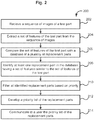
- FIG. 2 shows a schematic flow diagram of an exemplary method 200 for identifying a replacement part.
- the method 200 can be used with any system described herein, for example, the system 100, or, a non-transitory computer readable medium capable of being executed by a computing device, for example, the computing device 130, or 430.
- the method 200 includes receiving a sequence of images of a test part, at 202.
- the test part can include a screw, a bolt, a rivet, a nut, a washer, or any other test part, as described herein with respect to the test part 110.
- the sequence of images can be captured using any image capture device, for example, a smart phone, a tablet, a camera, or any other image capture device as described with respect to the imaging device 120 included in the system 100.
- the sequence of images can include a plurality of images captured from different angles to show different views of the test part.
- the sequence of images can include a video of the test part, for example, a 3-dimensional video, or
- a set of features of the test part are extracted from the sequence of images, at 204.
- the set of features can include a dimension, a shape, a texture, a color, a material, a thread count, a spectral characteristic, a histogram threshold, scale invariant features (e.g., Scale Invariant Feature Transform (SIFT), Speed-up-Robust Feature (SURF), etc.), and/or keypoint features (e.g., Binary Robust Invariant Scalable Keypoints (BRISK), Fast Retina Keypoint (FREAK), Binary Robust Independent Elementary Features (BRIEF), Oriented Fast, and Rotated BRIEF (ORB), etc.).
- SIFT Scale Invariant Feature Transform
- SURF Speed-up-Robust Feature
- keypoint features e.g., Binary Robust Invariant Scalable Keypoints (BRISK), Fast Retina Keypoint (FREAK), Binary Robust Independent Elementary Features
- the extracted set of features can at least include a dimension, a shape, a material, and a thread count of the test part.
- the sequence of images can include an object having a known shape, dimension, color, and texture (e.g., a penny). The object can serve as a reference object for extracting the set of features of the test part.
- the set of features of the test part can extracted using a computing device, for example, the computing device 130 included in the system 100, or any other computing device described herein (e.g., the computing device 430 described herein).
- instructions can be stored on a non-transitory computer readable medium which can be executed by a computing device (e.g., the computing device 130, or 430, as described herein) for extracting the set of features of the test part.
- the set of features of the test part can extracted using a Hough Transform.
- any number of instructions can be stored on the non-transitory computer readable medium described herein, for performing any of the operations described herein.
- the set of features of the test part are compared with a database of a plurality of replacement parts, at 206.
- the database stores a set of features of the replacement parts.
- the method 200 can also include populating the database of the plurality of replacement parts.
- the database can be populated by crawling a plurality of websites of suppliers of one or more of the replacement parts, and scraping information corresponding to the set of features of one or more of the replacement parts from each of the plurality of websites.
- the set of features of the replacement parts included in the database can include a shape, a texture, a color, a material, a thread count, a html link to at least one supplier, information on usability, and an image (e.g., a thumbnail image).
- the method 200 identifies at least one replacement part in the database having a set of features similar to the set of features of the test part, at 208.
- heuristics can be used to determine one or more replacement parts that have a set of features best matching the set of features of the test part.
- the dimensions of the test part and the replacement parts can be in units that do not match.
- the computing device 130 can extract dimension of the test part in SI units, while the dimensions of the replacement part are in inches or vice versa.
- the computing device can be configured to use a standard deviation to determine the closest match taking into account any error associated with computer vision metrology. If no replacement is discovered in the database, the set of features of the test part can be added to the database.
- the set of features of the identified replacement part stored in the database can be less than the set of features of the test part.
- the remaining features of the test part can be added to the database.
- All identified parts are filtered based on priority, at 210. This can include, for example, determining if more than one supplier of an identified replacement part is found, and selecting only a priority supplier of the identified replacement part to include in a priority list, as described herein.
- a priority list of replacement parts is developed, at 212. This can include, for example, sorting the identified replacement parts to include replacement parts having a set of features that best match the set of features of the test part to be arranged on top of the priority list. For example, certain features included in the set of features of the replacement part can be more relevant or pertinent in finding a replacement for the test part. For example, the thread counts, length, and width of a test part that includes a screw (also referred to as "the test screw”) can have higher priority relative to the size or shape of the head of the test screw. Thus, replacement screws having thread counts, length, and/or width similar to the test screw will have higher priority over replacement screws that have a similar head to the test screw.
- the priority list of the replacement parts is communicated to a user, at 214.
- the priority list of the replacement parts can be communicated to the user on a display (e.g., a monitor, a smartphone screen, or a tablet screen).
- the top one, two, or three replacement parts that were the closest match to the test part to the user can be displayed to the user.
- the display can include an interface, for example, a check box, pull down menu, or button to allow the user to view the other replacement parts included in the priority list.
- a method for identifying replacement parts for a test part can include hierarchical comparison of a set of features of a test part.
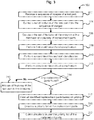
- FIG. 3 is a schematic flow diagram of an exemplary method 300 for identifying a replacement part.
- the method 300 can be used with any system described herein, for example, the system 100, or a non-transitory computer readable medium capable of being executing by a computing device, for example, the computing device 130, or 430 described herein.
- the method 300 includes receiving a sequence of images of a test part, at 302.
- the test part can include a screw, a bolt, a rivet, a nut, a washer, or any other test part, as described herein with respect to the system 100.
- the sequence of images can be captured using any image capture device, for example, a smart phone, a tablet, a camera, or any other image capture device, as described herein with respect to the imaging device 120 included in the system 100.
- the sequence of images can include a plurality of images captured from different angles to show different views of the test part.
- the test part can be a screw and the sequence of images can include a side view of the screw showing the thread count and length of the screw, a front head view showing the type of head of the screw, and/or a bottom view showing the tip of the screw as well as the radius.
- the sequence of images can include a video of the test part, for example, a 3 -dimensional video, or a video captured from different angles.
- the set of features of the test part are extracted from the sequence of images, at 304.
- the set of features can include a dimension, a shape, a texture, a color, a material, a thread count, a spectral characteristic, a histogram threshold, scale invariant features (e.g., Scale Invariant Feature Transform (SIFT), Speed-up-Robust Feature (SURF), etc.), keypoint features (e.g., Binary Robust Invariant Scalable Keypoints (BRISK), Fast Retina Keypoint (FREAK), Binary Robust Independent Elementary Features (BRIEF), Oriented Fast, and Rotated BRIEF (ORB), etc.), and/or any other physical or computational feature relevant to identification of the test part.
- scale invariant features e.g., Scale Invariant Feature Transform (SIFT), Speed-up-Robust Feature (SURF), etc.
- keypoint features e.g., Binary Robust Invariant
- the test part can include a screw, a bolt, or a nut.
- the extracted features can at least include a dimension, a shape, a material, and a thread count of the test part.
- the sequence of images of the test part can also include an object having a known shape, dimension, color, and texture (e.g., a penny). The object can serve as a reference for extracting the set of features of the test part.
- the set of features of the test part can be extracted using a computing device, for example, the computing device 130 included in the system 100, the computing device 430, or any other computing device described herein.
- instructions can be stored on a non-transitory computer readable medium which can be executed by a computing device (e.g., the computing device 130 or 430) for extracting the set of features of the test part.
- the set of features can be extracted using a Hough Transform.
- any number of instructions can be stored on the non-transitory computer readable medium described herein for performing any of the operations described herein.
- the set of features of the test part are compared with a database of a plurality of replacement parts, at 306.
- the database can, for example, be stored on a computer readable medium.
- the database stores a set of features of the plurality of replacement parts.
- the database can be populated by crawling a plurality of websites of suppliers of one or more of the replacement parts and scraping information corresponding to the set of features of one or more of the replacement parts from each of the plurality of websites.
- the set of features of the replacement parts included in the database can include a shape, a texture, a color, a material, a thread count, a html link to at least one supplier, information on usability, and an image (e.g., a thumbnail image).
- Models of the replacement parts can be trained using images of replacement parts and/or super vector features, which can be Gaussian Mixture Models (GMMs), Convolutional Neural Networks (CNNs), Radial Basis Functions (RBFs), and/or other kernels and a classifier, such as Support Vector Machines (SVMs) and/or Linear Discriminant Functions, can be constructed.
- the classifier can include, for example, a hierarchical classifier which can order or otherwise arrange the set of features of the replacement part into in predetermined classes or hierarchy.
- the set of features of the replacement parts can include information on shape, texture, color, material, thread count, a html link to at least one supplier, information on usability, and/or image (e.g., a thumbnail image).
- the replacement parts can also be classified into hierarchical classifiers based on type in the database. For example, the replacement parts can be classified into a first-level hierarchical classification as a fastener, or another part. If the replacement part is a fastener, a second-level hierarchical classification can be performed to classify the replacement part as a fastener with a head, or a round a fastener. If the replacement part is a fastener with a head, a third-level hierarchical classification can be performed to classify the replacement part as a screw, a bolt, or a rivet. Alternatively, if the replacement part is a round fastener, the third-level classification can classify the replacement part as a nut or a washer. Further classifications can also be performed based on the set of features of the replacement parts. Classifying the replacement parts can facilitate identification of one or more replacement parts having a set of features similar to the set of the features of the test part using hierarchical comparison, as described herein.
- a first-level hierarchical classification is performed, at 308.
- the first-level hierarchical classification can determine if the test part is a fastener, or any other part.
- the fastener can include a fastener with a head (e.g., a screw, a bolt, or a rivet), or a round fastener (e.g., a nut or a washer).
- a second-level hierarchical classification is performed, at 310. For example, if the first-level classification determined that the test part is a fastener, the second-level hierarchical classification can determine if the test part is a fastener with a head, or a round fastener. Expanding further, the test part can be a screw and the second-level classification can determine that the test part is a fastener with a head. Alternatively, the test part can be a nut, and the second level classification can determine that the test part is a round fastener.
- a third-level hierarchical classification is performed, at 312.
- the third-level hierarchical classification can determine a sub-type of the test part. Expanding further, the third-level classification can determine whether the test part is a screw, a bolt or a rivet, if the second-level classifier determined the test part to be fastener with a head. Similarly, the third-level classification can determine whether the test part is a nut or a washer, if the second-level classifier determined the test part to be a round fastener.
- a sub-level classification can classify the replacement test part based on the set of features of the test part.
- the test part can be a screw and a first sub-level classification can determine the material of the screw, a second sub-level classification can determine the thread count of the screw, a third sub-level classification can determine the color of the screw, and so on, not necessarily in that order.
- the method determines if any replacement part is found, at 314. Expanding further, the method 300 determines if there are one or more replacement parts in the database that include a set of features which are similar to the set of features of the test part. If no replacement part having a set of features similar to the set of features of the test part is found in the database, the set of features of the test part are added to the database, at 316. In this way, the database can continue evolving to include any new replacement parts not already included in the database. In some instances, replacement parts can be found that have a set of features that are less than the set of features of the test part. In another words, the number of features of the replacement parts included in the set of features of the replacement part is less than the number of the set of features of the test part. In such instances, the remaining set of features of the test part can also be added to the database.
- the filtering based on priority can include determining if more than one supplier of an identified replacement part is found, and selecting only a priority supplier of the identified replacement part to include in a priority list, as described herein.
- a priority list of replacement parts is developed, at 320. This can include, for example, sorting the identified replacement parts to include replacement parts having a set of features that best match the set of features of the test part to be arranged on top of the priority list. For example, certain features included in the set of features of the replacement part can be more relevant or pertinent in finding a replacement for the test part. For example, the thread counts, length, and width of a test part that includes a screw (also referred to as "the test screw”) can have higher priority relative to the size or shape of the head of the test screw. Thus, replacement screws having thread counts, length, and/or width similar to the test screw will have higher priority over replacement screws that have a similar head to the test screw.
- the priority list of replacement parts is communicated to a user, at 322.
- the priority list of the identified replacement parts can be displayed to the user on a display (e.g., a monitor, a smartphone, or a tablet display). It is possible to display only a subset of the identified replacement parts to the user, for example, the top three identified replacement parts.
- a drop down menu or any other option can be provided to the user to view all other identified replacement parts that are not initially displayed to the user.
- the user can provide an indication that a replacement part was indeed a correct replacement part. This indication can be integrated into the database and used in selecting replacement parts for future searches.
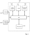
- FIG. 4 is a block diagram of a computing device 430 in accordance with an illustrative implementation.
- the computing device 430 includes a bus 432 or other communication component for communicating information and a processor 434 or processing circuit coupled to the bus 432 for processing information.
- the computing device 430 can also include one or more processors 434 or processing circuits coupled to the bus for processing information.
- the computing device 430 also includes main memory 436, such as a random access memory (RAM) or other dynamic storage device, coupled to the bus 432 for storing information, and instructions to be executed by the processor 434.
- Main memory 436 can also be used for storing position information, temporary variables, or other intermediate information during execution of instructions by the processor 434.
- the computing device 430 may further include a read only memory (ROM) 438 or other static storage device coupled to the bus 432 for storing static information and instructions for the processor 434.
- ROM read only memory
- a storage device 440 such as a solid-state device, magnetic disk or optical disk, is coupled to the bus 440 for persistently storing information and instructions.
- the computing device 430 may be coupled via the bus 432 to a display 444, such as a liquid crystal display, or active matrix display, for displaying information to a user.
- a display 444 such as a liquid crystal display, or active matrix display
- An input device 442 such as a keyboard including alphanumeric and other keys, may be coupled to the bus 432 for communicating information and command selections to the processor 434.
- the input device 442 has a touch screen display 444.
- the input device 442 can include a cursor control, such as a mouse, a trackball, or cursor direction keys, for communicating direction information and command selections to the processor 434 and for controlling cursor movement on the display 444.
- the processes and methods described herein can be implemented by the computing device 430 in response to the processor 434 executing an arrangement of instructions contained in main memory 436.
- Such instructions can be read into main memory 436 from another non-transitory computer-readable medium, such as the storage device 440.
- Execution of the arrangement of instructions contained in main memory 436 causes the computing device 430 to perform the illustrative processes described herein.
- processors in a multi-processing arrangement may also be employed to execute the instructions contained in main memory 436.
- hard-wired circuitry may be used in place of or in combination with software instructions to effect illustrative implementations. Thus, implementations are not limited to any specific combination of hardware circuitry and software.
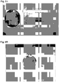
- FIG. 5A and 5B are exemplary images of a test part which includes a blunt head screw.
- the images can be used to extract the set of features of the screw using any of the system and methods described herein, for example, the system 100, or the methods 200, or 300.
- FIG. 5A is a first image of a screw taken from the side (i.e., a top-down aerial view) to show the thread count, thread length, total length, diameter of head, and depth of the head of the screw.
- a penny is also included in the first image as a reference object.
- a circle Hough Transform is performed on the penny to extract the set of features of the penny for use as reference features for the screw.
- a first-level hierarchical classification is performed on the first image to determine if the test part (i.e., the blunt head screw) is: (1) a part with a head (i.e., a screw or a bolt); (2) a round part (i.e., a washer, a nut, etc.), or; (3) any other object.
- the test part i.e., the blunt head screw
- a part with a head i.e., a screw or a bolt
- a round part i.e., a washer, a nut, etc.
- the system or method can determine that the test part is a part with a head. Furthermore, the system or method can also determine the diameter of the head of the screw, the total length of the screw, the depth of the screw, the length of the threaded portion of the screw, and the diameter of the base of the screw.
- a line Hough Transform can be used to determine the thread count of the screw.
- Preprocessing of the image can also be performed on the image to obtain before extracting the set of features. Such preprocessing can include, for example, converting the image from color into a binary image (e.g., black and white or grayscale) which can make it easier to apply the transforms.
- the first-level classification can classify the test part as a round part. Furthermore, the first level classification can also determine the inner and outer diameter of the washer or nut. The outer diameter can be determined using distance from one flat to the adjacent flat side, and/or distance from one corner to another corner (e.g., using the Whitworth system).
- FIG. 5B is a second image of the blunt head screw captured from the front to show the head of the screw. This can be used to determine the head type of the screw.
- a second-level classification can determine if the head type of the screw is round, hex, or square.
- a third-level classification can determine a sub-type of the screw.
- the third-level classification can determine if the screw is dome or flat, and if the drive type is Philips, flat, Allen, torx 6, security torx 6, etc.
- the third-level classification or any sub-level classification can also determine a length of the major axis of the drive of the screw.
- Various strategies can be used to determine the major axis of the drive of the screw.
- the drive type is a cross, so the drive type includes two major axes which are the same length.
- the major axis is a single axis.
- the major axis can be from any corner to an adjacent corner.
- the major axis can be from any corner to an adjacent corner.
- the major axis can be from any corner to an adjacent corner.
- the test part shown in FIGS. 5A and 5B is a blunt head screw ( FIG. 5B ) which does not include a drive, no major axis will be extracted for the screw.
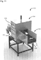
- FIGS. 6-11 show an automated machine 500 for capturing images of a batch of replacement parts which can be uploaded to a computing device (e.g., the computing device 130 described herein) to extract the set of features of the batch of the replacement parts.
- the machine 500 includes a loading portion 502, an imaging portion 504, and a recovery portion 506.
- the machine 500 also includes a conveyor belt 508, a plurality of imaging devices 520a-f, and optionally, a computing device 530.
- a replacement part R included in a batch of replacement parts can be disposed on the conveyor belt 508 in the loading portion 502 of the machine 500.
- the conveyor belt 508 can be mounted on rollers and can be configured to move continuously through the machine 500 to carry the replacement part R from the loading portion 502, to the recovery portion 506 through the imaging portion 504.
- the conveyor belt 508 can be formed from a substantially transparent material such as, for example, polycarbonate, acrylic, plastic, any other suitable material or a combination thereof. This can allow viewing of the replacement part R from below.
- FIG. 7 shows the replacement part R traveling on the conveyor belt 508 into the imaging portion 504.
- a first imaging device 520a e.g., a camera
- a second imaging device 520b is disposed in the imaging portion 504 below the conveyor belt 508.
- the second imaging device 520b is configured to capture an image of the replacement part R from below, through the conveyor belt 508.
- FIG. 9 shows a third imaging device 520c and a fourth imaging device 520b disposed in the imaging portion 504.
- the third imaging device 520c and the fourth imaging device 520f are disposed and oriented to capture images of the front of the replacement part R from two different angles.
- a fifth imaging device 520e and a sixth imaging device 520f are also disposed in the imaging portion 504, which are disposed and oriented to capture images of the back of the replacement part R from two different angles.
- each of the imaging devices 520c-f can be disposed in the imaging portion 504 so as to capture images of the replacement part R from four different angles around the replacement part R.
- the third imaging device 520c can be oriented at a 45 degree angle relative to a central axis of the replacement part R and in the same plane as the central axis.
- the fourth imaging device 520d can be disposed at a 135 degree angle
- the fifth imaging device 520e can be disposed at a 225 degree angle
- the sixth imaging device 520f can be disposed at a 315 degree angle with respect to the central axis of the replacement part R in the same plane.
- the imaging devices 520a-f in combination can capture 360 degree images of the replacement part R.
- the imaging portion 504 can also include sensors configured to detect that a replacement part R is present in the imaging portion 504, and to trigger the imaging devices 520a-f to capture images of the replacement part R.
- Suitable sensors can include, for example, motion sensors, weight sensors, laser sensors, infrared sensors, any suitable sensors or combination thereof.
- the machine 500 can be configured such that each of the imaging devices 520a-f capture images of the replacement part R simultaneously.
- the machine 500 can be configured such that the imaging device 520a-f capture images of the replacement part R sequentially.
- the imaging portion 504 can also include lighting to allow the images to be captured with a predetermined brightness and/or contrast.
- the replacement part R can continue travelling on the conveyor belt 508 through the imaging portion 504 and into the receiving portion 506 where it can be collected or otherwise removed from the conveyor belt 508.
- the conveyor belt 508 can be configured to run continuously such that a batch of replacement parts can be loaded on the machine 500 one after the other and the imaging devices 520a-f can continuously capture images of the replacement parts.
- the machine can be configured to assign ID's to each replacement part imaged such that the images can be correlated to the correct replacement part.
- a computing device 530 can optionally be included in the machine 500.
- the computing device 530 can be substantially similar to the computing device 130 described herein.
- the computing device 530 can be configured to receive the images of the batch of replacement parts and extract the set of features of the replacement parts included in the batch.
- the set of features of the batch of replacement parts can be used to build a database of replacement parts or add the set of features to a preexisting database.
- the computing device can be a remote server disposed remotely from the machine 500.
- the machine 500 can be configured to store and/or transfer data to the remote computing device for extracting the set of features.
- the machine 500 can include Wi-Fi, wired internet connection (e.g., cable or DSL), BLUETOOTH®, USB 2.0, IEEE firewire, any other suitable technology for communicating the captured images to the remote computing module.
- the machine 500 can also include a display, for example, to view the captured images of the replacement part. In this manner, a user can determine if the captured images of the replacement part are of sufficient quality for extracting the set of features.
- the machine 500 can also include an input, for example, a touch screen or a keyboard to control one or more parameters of the machine. For example, the input can be used to control the speed of the conveyor belt, lighting intensity, camera shutter speed, or any other parameters of the machine 500.
- the machine 500 can also be used to capture images of a test part.
- the images of the test part can then be used to extract the set of features of the test part for comparison with the database of replacement parts to identify a best match replacement part for the test part.
- Capturing images of the replacement parts as well as the test part using the machine 500 can ensure that a similar set of images is captured for the test part to extract its set of features, relative to the set of images used to extract the set of features of the replacement parts which are used to populate the database. This can enhance the fidelity of the replacement part identification process by reducing or otherwise eliminating any errors due to low quality images associated with human error.
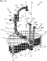
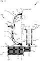
- FIGS. 12-18 show another embodiment of an imaging device 600 for capturing 3-dimensional images of a replacement part R.
- the imaging device 600 includes a base 602, an imaging assembly 610, and a holder assembly 640.
- the base 602 can be substantially flat and is mounted on a frame 604.
- the base 602 can be formed from a strong and rigid material, for example aluminum, steel, wood, plastics, etc.
- the base 602 has a hemispherical shape as shown in FIGS. 12-17 .
- the base 602 can have any suitable shape, for example square, rectangular, oval, polygonal, etc.
- the frame 604 includes a plurality of posts 605 for positioning the imaging system 600 securely on a surface such as a floor.
- the posts 605 can be configured to adjusting a height of the base 602 or to level the base 602.
- the posts 605 can include lead screws which can be threaded into or out of the frame 605 for adjusting a distance of an end of the posts 605 proximal to the surface, to the base 602.
- wheels can be coupled to the frame in place of or in addition to the posts 605 so that the imaging system 600 can be transported from a first location to a second location by rolling on the wheels.
- a platform 603 is coupled to the base 602 and positioned adjacent to the base 602.
- the platform 603 can include a substantially flat member which extends from the base 602. While shown in FIGS. 12-17 as having a triangular shape, in other embodiments the platform 603 can have any other suitable shape (e.g., square, rectangular, circular, hemispherical, oval, etc.).
- the holder assembly 640 is mounted on the platform 603 such that the replacement part R gripped in the holder assembly 640 is positioned in a line of sight of an imaging device 630 included in the imaging assembly 610, as described herein.
- the platform 603 can be monolithically formed with the base 602, for example formed with the base 602 during a machining, milling, casting or molding process.
- the platform 603 can be a separate part fixedly or removable coupled to the base 602, for example using rivets, screws, nuts, bolts, etc.
- At least one storage drawer 608 can be disposed below the base 602.
- the storage drawer 608 can be moved (e.g., pulled) distally relative to the base 602 in the direction shown by the arrows C in FIG. 17 , to access the storage drawer 608.
- the storage drawer 608 can be used to store spare parts or replacement parts.
- the imaging assembly 610 includes a first arm 612 and a second arm 622.
- the first arm 612 includes a first arm first portion 613 and a first arm second portion 614 distal from the first arm first portion 613.
- the first arm 613 is pivotally mounted on the base 602 at the first arm first portion 613 on a first pivot mount 616.
- the first arm 612 is rotatable about the first pivot mount 616 about a vertical axis A v of the imaging system 600.
- the first arm 612 is rotatable about the first pivot mount 616 by an angle of about 180 degrees ( FIG. 15 ).
- the first arm 612 can be manually rotated about the first pivot mount 616.
- an actuator for example a servo motor can be coupled to the first pivot mount 616 for rotating the first arm 612 about the first pivot mount 616.
- the first arm first portion 613 can be fixedly mounted to the base 602.
- the first arm 612 can be positioned such that the first arm second portion 614 is substantially parallel to the holder assembly 640 along a horizontal axis A H of the imaging system 600, as shown in in FIG. 13 .
- At least a portion of the first arm first portion 613 proximal to the first pivot mount 616 is parallel to the base 602. Furthermore, at least a portion of the first arm second portion 614 is substantially perpendicular to the base 602 and parallel to the vertical axis A v of the imaging system 600.
- the first arm 612 also includes a first arm third portion 615 connecting the first arm first portion 613 and the first arm second portion 614.
- the first arm third portion 615 defines a radius curvature of about 90 degrees such that the first arm first portion 613 is positioned proximal to the platform 603 and the first arm second portion 614 is positioned distal from the platform 603.
- the first arm third portion 615 extends from the first portion 613 towards an end of the base 602 distal from the holder assembly 640. Furthermore, the first arm third portion 615 curves by an angle of about 90 degrees such that the first arm second portion 614 is positioned distal to the holder assembly 640 relative to the first pivot mount 616 and the first arm first portion 613.
- the first arm first portion 613 can include a substantially straight member extending away from the first pivot mount 616 parallel to the base 602 distal relative to the holder assembly 640.
- the second arm second portion 614 can also include a substantially straight member extending orthogonally from an end of the first arm first portion 613 distal to the base 602 and parallel to the vertical axis A v of the imaging system 600, such that the curved first arm third portion 615 is not included in the first arm 612.
- the second arm 622 includes a second arm first portion 623 and a second arm second portion 624.
- the second arm 622 is pivotally mounted on the first arm second portion 614 at the second arm first portion 623 on a second pivot mount 626.
- At least a portion of the second arm first portion 623 proximal to the second pivot mount 626 is orthogonal to the base 602 and substantially parallel to the vertical axis A v , and extends away from the first arm second portion 614.
- at least a portion of the second arm second portion 624 is substantially parallel to the base 602 and orthogonal to the vertical axis A v of the imaging system 600.
- An imaging device 630 e.g., a charged coupled device (CCD) camera, an infrared camera or any other suitable imaging device as described herein
- CCD charged coupled device
- the second arm 624 also includes a second arm third portion 625 connecting the second arm first portion 623 and the second arm second portion 624. Similar to the first arm third portion 615, the second arm third portion 625 also defines a radius of curvature of about 90 degrees such that the second arm first portion 623 is positioned distal to the platform 603 and the second arm second portion 624 is positioned proximal to the platform along the horizontal axis A H of the system 600. In other words, the second arm third portion 625 extends from the second arm first portion 623 towards an end of the base 602 proximal to the holder assembly 640. Furthermore, the second arm third portion 625 curves by an angle of about 90 degrees such that the second arm second portion 624 is positioned proximal to the holder assembly 640 relative to the second pivot mount 626 and the second arm first portion 623.
- the second arm first portion 623 can include a substantially straight member extending away from the second pivot mount 626 orthogonal to the base 602 and distal relative to the base 602.
- the second arm second portion 624 can also include a substantially straight member extending orthogonally from an end of the second arm first portion 613 distal to the base 603, and parallel to the base 602, such that the curved second arm third portion 625 is not included in the second arm 622.
- the second arm 622 is rotatable about the second pivot mount 626 to rotate the imaging device 630 about an axis of the system 600 shown by the axis AA.
- the axis AA defines an axis of the second pivot mount 626 which is orthogonal to the vertical axis A v but in the same plane as the horizontal axis A H of the system 600.
- the axis AA is rotatable about the vertical axis A v via the rotation of the first arm 612 about the first pivot mount 616, for example by an angle of about 180 degrees. This allows 360 degree rotation of the second arm 622 and thereby, the imaging device 630 about the rotatable axis AA ( FIG.
- the imaging device 630 can be positioned at a plurality of angles around the replacement part R to allow imaging of the replacement part R from the plurality of angles. More specifically, the imaging device 630 can be positioned at any point on a contoured plane surrounding the replacement part R which is defined by a hemispherical dome.
- the imaging device 630 can be moved to take images from different angles. For example, the imaging device 630 can be moved to take pictures at a 5 degree offset on a particular axis. Images captured from smaller offsets, e.g., less than 10 degrees, can be used to help identify images of replacement parts that have a small degree of error. For example, a picture taken from the top of the replacement part may be off by a small offset, e.g., less than 10 degrees. The additional images of the replacement part that also include small offsets can be used to help identify the replacement part per the methods described above.
- a first actuator 650 is coupled to the second arm 622.
- the first actuator 650 can include a linear actuator configured to displace the second arm 622 proximally or distally relative to the replacement part R mounted on the holder assembly 640, as described herein.
- the second arm 622 is disposed to position the imaging device 630 distal to the base 602 and in line with the vertical axis A v of the system 600.
- the first actuator 650 moves the second arm 622 and thereby, the imaging device 630 proximally or distally relative to the base 602 by a predetermined distance Y. This can for example, allow focusing, capturing a zoomed in or a zoomed out image of the replacement part R.
- the second arm 622 can be manually rotated about the second pivot mount 626.
- a second actuator for example a servo motor can be coupled to the second pivot mount 626 for rotating the first arm 612 about the second pivot mount 626.
- the holder assembly 640 is configured to position the replacement part R in the line of sight of the imaging device 630 and further to allow rotation of the imaging device 630 about the replacement part R such that images of the replacement part R can be captured from a plurality of angles.
- the holder assembly 640 includes a base mount 642 mounted on the platform 603.
- the base mount 642 is pivotally mounted on the platform and is configured to rotate, for example by an angle of 360 degrees on the platform about a second vertical axis BB defined by the base mount 642.
- the second vertical axis is parallel to the vertical axis A v of the system 600.
- the base mount 642 has a first end and a second end opposite the first end.
- a first strut 644a is coupled to the first end of the base mount 642, and a second strut 644b is coupled to a second end of the base mount 642.
- the first strut 644a and the second strut 644b extend parallel to the vertical axis A v of the system 600 and also parallel to the second vertical axis BB.
- the first strut 644a and the second strut 644b can include bars or rods formed from a rigid material, for example, plastics.
- the image system 600 includes multiple image devices (not shown).
- the image system 600 can include the image device 630 and one or more other image devices.
- the image system 600 can include an image device on either the first arm or the second arm such that the image device's line of sight is parallel to the horizontal axis A H of the imaging system 600.
- the imaging system 600 can also include an imaging device positioned on the first arm such that the image device's line of sight is at a 45 degree angle from the horizontal axis A H of the imaging system 600.
- Use of additional image devices allow for multiple images to be captured at the same time, reducing the amount of movement of the first arm and the second arm needed to capture all required images.
- a first stage 646a is coupled to the first strut 644a and a second strut 646b is coupled to the second strut 644b.
- a first gripper 648a and a second gripper 648b are coupled to the first stage 646a and the second stage 646b, respectively.
- the grippers are made of a clear or translucent material, allowing the imaging device to take a picture of the replacement part without or minimizing the interference from the gripper.
- the first stage 646a and the second stage 646b can include flat members configured to provide a flat and stable surface to dispose the grippers thereon.
- the first stage 646a and the second stage 646b can provide coupling means for coupling the grippers to the stages.
- first stage 646a and the second stage 646b can define threaded openings (e.g., to allow coupling of the grippers via screws, nuts, bolts, etc.), a clip, a jaw, a snap-fit mechanism, or any other coupling mechanism for fixedly or removably coupling the grippers to the stages.
- first gripper 648a and the second griper 648b can be coupled directly to the first strut 644a and the second strut 644b such that the first stage 646a and the second stage 646b are not included in the holder assembly 600.
- first stage 646a and the second stage 646b are positioned orthogonal to the first strut 644a and the second strut 644b.
- the first stage 646a extends parallel to the base 602 in a first direction and the second stage 646b extends parallel to the base 602 in a second direction opposite the first direction, as seen in FIG. 12 .
- the base mount 642 can be rotated to position at least one of the struts, for example the first strut 644a proximal to the base 602.
- the first stage 646a is parallel to the horizontal axis A H of the system 600 and orthogonal to the vertical axis A v of the system 600.
- At least a portion of the first gripper 648a is disposed over the base 602 such that the replacement part R gripped by the first gripper 648 is also disposed over the base 602 and in the line of sight of the imaging device 630.
- the imaging device 630 can be positioned at various positions around the replacement part R in the first configuration, as described before, to capture images of the replacement part R from a plurality of angles.
- the second stage 646b is also parallel to the horizontal axis A H and orthogonal to the vertical axis Ay, but extends away from the base 602 in the first configuration.
- a second replacement part Rl can be disposed in the second gripper 648b, for example as shown in FIGS. 16 and 17 .
- the holder assembly 640 can be moved into a second configuration.
- an actuator can be used to signal that the image system 600 should begin capturing images of the second replacement part Rl .
- the base mount 642 can be rotated about the axis BB until the second gripper 648b is positioned over the base 602 to position the second replacement part Rl in the line of the sight of the imaging device 630.
- the imaging device 630 can now be used to capture images of the second replacement part Rl from a plurality of angles as described before.
- the replacement part R which has already been imaged can now be removed from the first gripper 648a and a third replacement part can be disposed in the first gripper 648a.
- plurality of replacement parts can be imaged by the imaging system 600 by moving the holder assembly between the first configuration and the second configuration.
- the holder assembly can include only one strut, for example the first strut 648a mounted on the base mount 642.
- the replacement part R can be mounted on the first gripper 648a and the base mount 642 rotated to dispose the first gripper 648a over the base 602 such that the replacement part R can be imaged as described before.
- the base mount 642 can be rotated to move the first gripper 648a distal to the base 602 for removing the imaged replacement part R.
- a second replacement part can then be mounted on the first gripper 648a and the base mount 642 rotated again to position the first gripper 648a over the base and allowing imaging of the second replacement part.
- the base mount 642 can include only one strut (e.g., the first strut 644a) fixedly mounted on the platform 603 such that the first gripper 648a is fixedly disposed over the base 602.
- the first gripper 648a and the second gripper 648b can include clips, jaws, slots or any other mechanism for holding or otherwise gripping the replacement part R.
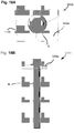
- FIGS. 18A and 18B show one embodiment of the first gripper 648a.
- the first gripper 648a includes a first leg 649a and a second leg 649b defining a slot therebetween, as shown in FIGS. 18A and 18B .
- the slot is configured to hold or otherwise grip the replacement part R.
- the slot extends from one end of the first gripper 648a to a predetermined length of the first gripper 648a. In some embodiments, the slot is sized to be slightly smaller than a cross-section of the replacement part R.
- the first leg 649a and the second leg 649b are pulled slightly apart to increase the width of the slot to dispose the replacement part R therewithin. Once the replacement part R is disposed in the slot, the first leg 649a and the second leg 649b snap towards each other to grip the replacement part R therebetween.
- an enclosure can be disposed over the base 602.
- FIGS. 16-17 show an embodiment of an enclosure 660 disposed over the base 602.
- the enclosure 660 includes a semi-circular sidewall 662 disposed around the base 602 and a roof 664 disposed over the sidewall 662 parallel to the base 602.
- the enclosure 660 can also include a door (not shown) which can be closed once the replacement part R is positioned for imaging over the base 602. This allows imaging of the replacement part R inside the enclosure isolated from ambient light.
- one or more lighting devices e.g., incandescent lights or LED lights
- the lighting devices can be disposed inside the enclosure 660 to provide suitable lighting for capturing high quality images of the replacement part R.
- the imaging system 600 can produce a number of images of the replacement part from numerous different angles and/or positions. For example, as explained above, a number of features of a replacement part are extracted from a sequence of images of the replacement part.
- the imaging system 600 can be used to generate the sequence of images of replacement parts. For example, the imaging system 600 can take images of a replacement every n degrees, such as, 10, 15, 30, 45 degrees, etc., of the movement of the second arm. In addition, the imaging system 600 can take images of the replacement part every m degrees, such as, 10, 15, 30, 45 degrees, etc., of the first arm's movement. Combining the movement of the first arm and the second arm with the image device capturing images, the sequence of images for the replacement part can be captured.
- the image device names the images accordingly. For example, an image name can include the first arm position and the second arm position. A unique identifier can be used that corresponds with the replacement part. This allows the images to be easily processed after they have been captured.
- Implementations described in this specification can be implemented in digital electronic circuitry, or in computer software, firmware, or hardware, including the structures disclosed in this specification and their structural equivalents, or in combinations of one or more of them.
- the implementations described in this specification can be implemented as one or more computer programs, i.e., one or more modules of computer program instructions, encoded on one or more computer storage media for execution by, or to control the operation of, data processing apparatus.
- the program instructions can be encoded on an artificially-generated propagated signal, e.g., a machine-generated electrical, optical, or electromagnetic signal that is generated to encode information for transmission to suitable receiver apparatus for execution by a data processing apparatus.
- a computer storage medium can be, or be included in, a computer-readable storage device, a computer-readable storage substrate, a random or serial access memory array or device, or a combination of one or more of them.
- a computer storage medium is not a propagated signal, a computer storage medium can be a source or destination of computer program instructions encoded in an artificially-generated propagated signal.
- the computer storage medium can also be, or be included in, one or more separate components or media (e.g., multiple CDs, disks, or other storage devices). Accordingly, the computer storage medium is both tangible and non-transitory.
- the operations described in this specification can be performed by a data processing apparatus on data stored on one or more computer-readable storage devices or received from other sources.
- data processing apparatus or “computing device” encompasses all kinds of apparatus, devices, and machines for processing data, including by way of example a programmable processor, a computer, a system on a chip, or multiple ones, or combinations of the foregoing.
- the apparatus can include special purpose logic circuitry, e.g., an FPGA (field programmable gate array) or an ASIC (application-specific integrated circuit).
- the apparatus can also include, in addition to hardware, code that creates an execution environment for the computer program in question, e.g., code that constitutes processor firmware, a protocol stack, a database management system, an operating system, a cross-platform runtime environment, a virtual machine, or a combination of one or more of them.
- code that creates an execution environment for the computer program in question e.g., code that constitutes processor firmware, a protocol stack, a database management system, an operating system, a cross-platform runtime environment, a virtual machine, or a combination of one or more of them.
- the apparatus and execution environment can realize various different computing model infrastructures, such as web services, distributed computing and grid computing infrastructures.
- a computer program (also known as a program, software, software application, script, or code) can be written in any form of programming language, including compiled or interpreted languages, declarative or procedural languages, and it can be deployed in any form, including as a stand-alone program or as a module, component, subroutine, object, or other unit suitable for use in a computing environment.
- a computer program may, but need not, correspond to a file in a file system.
- a program can be stored in a portion of a file that holds other programs or data (e.g., one or more scripts stored in a markup language document), in a single file dedicated to the program in question, or in multiple coordinated files (e.g., files that store one or more modules, sub-programs, or portions of code).
- a computer program can be deployed to be executed on one computer or on multiple computers that are located at one site or distributed across multiple sites and interconnected by a communication network.
- processors suitable for the execution of a computer program include, by way of example, both general and special purpose microprocessors, and any one or more processors of any kind of digital computer.
- a processor will receive instructions and data from a read-only memory or a random access memory or both.
- the essential elements of a computer are a processor for performing actions in accordance with instructions and one or more memory devices for storing instructions and data.
- a computer will also include, or be operatively coupled to receive data from or transfer data to, or both, one or more mass storage devices for storing data, e.g., magnetic, magneto-optical disks, or optical disks.
- mass storage devices for storing data, e.g., magnetic, magneto-optical disks, or optical disks.
- a computer need not have such devices.
- a computer can be embedded in another device, e.g., a mobile telephone, a personal digital assistant (PDA), a mobile audio or video player, a game console, a Global Positioning System (GPS) receiver, or a portable storage device (e.g., a universal serial bus (USB) flash drive), to name just a few.
- Devices suitable for storing computer program instructions and data include all forms of non-volatile memory, media and memory devices, including by way of example semiconductor memory devices, e.g., EPROM, EEPROM, and flash memory devices; magnetic disks, e.g., internal hard disks or removable disks; magneto-optical disks; and CD-ROM and DVD-ROM disks.
- the processor and the memory can be supplemented by, or incorporated in, special purpose logic circuitry.
- a member is intended to mean a single member or a combination of members
- a material is intended to mean one or more materials, or a combination thereof.
- the terms "about” and “approximately” generally mean plus or minus 10% of the stated value. For example, about 0.5 would include 0.45 and 0.55, about 10 would include 9 to 11, about 1000 would include 900 to 1100.
- Coupled means the joining of two members directly or indirectly to one another. Such joining may be stationary (e.g., permanent) or moveable (e.g., removable or releasable). Such joining may be achieved with the two members or the two members and any additional intermediate members being integrally formed as a single unitary body with one another or with the two members or the two members and any additional intermediate members being attached to one another.
Landscapes
- Engineering & Computer Science (AREA)
- General Engineering & Computer Science (AREA)
- Mechanical Engineering (AREA)
- Multimedia (AREA)
- Signal Processing (AREA)
- Image Analysis (AREA)
- Physics & Mathematics (AREA)
- Computer Graphics (AREA)
- General Physics & Mathematics (AREA)
- Theoretical Computer Science (AREA)
- Geometry (AREA)
- Software Systems (AREA)
Claims (15)
- Bildgebungssystem, umfassend:eine Basis (602);eine Bildgebungsanordnung (610), umfassend:einen ersten Arm (612), der einen ersten Abschnitt eines ersten Arms (613) und einen zweiten Abschnitt eines ersten Arms (614) distal von dem ersten Abschnitt des ersten Arms beinhaltet, wobei der erste Arm schwenkbar auf der Basis an dem ersten Abschnitt des ersten Arms auf einer ersten Schwenkhalterung (616) montiert ist,einen zweiten Arm (622), der einen ersten Abschnitt eines zweiten Arms (623) und einen zweiten Abschnitt eines zweiten Arms (624) distal von dem ersten Abschnitt des zweiten Arms beinhaltet, wobei der zweite Arm schwenkbar auf dem zweiten Abschnitt des ersten Arms an dem ersten Abschnitt des zweiten Arms auf einer zweiten Schwenkhalterung (626) montiert ist, undeine Bildgebungsvorrichtung (630), die auf dem zweiten Abschnitt des zweiten Arms montiert ist; gekennzeichnet durcheine Halteranordnung (640), umfassend:eine Basishalterung (642), die auf einer Plattform, die an die Basis gekoppelt ist, montiert ist,eine Strebe (644a), die an die Basishalterung gekoppelt ist, undeinen Greifer (648a), der an die Strebe gekoppelt ist, wobei der Greifer konfiguriert ist, ein Teil zu greifen,wobei der zweite Arm um die zweite Schwenkhalterung drehbar ist, um die Bildgebungsvorrichtung um eine Achse (AA) des Systems um das Teil herum derart zu drehen, dass das Teil aus einer Vielzahl von Winkeln durch die Bildgebungsvorrichtung abgebildet wird.
- System nach Anspruch 1, wobei mindestens ein Abschnitt des Greifers über der Basis derart positioniert ist, dass das Teil in einer Sichtlinie der Bildgebungsvorrichtung ist.
- System nach Anspruch 1 oder 2, wobei der erste Arm um die erste Schwenkhalterung um eine vertikale Achse des Systems drehbar ist, optional um einen Winkel von 180 Grad.
- System nach Anspruch 1 oder 2, ferner umfassend:einen Aktor (650), der an den zweiten Arm gekoppelt ist, wobei der Aktor konfiguriert ist, den zweiten Arm mindestens eines von proximal und distal relativ zu dem Teil zu verschieben; und optionaleinen zweiten Aktor, der auf der zweiten Schwenkhalterung montiert ist, wobei der zweite Aktor konfiguriert ist, den zweiten Arm um die zweite Schwenkhalterung zu drehen.
- System nach Anspruch 1 oder 2, ferner umfassend:
ein Gehäuse (660), das über der Basis und um die Bildgebungsanordnung herum angeordnet ist. - System nach Anspruch 1 oder 2, ferner umfassend:
mindestens ein Aufbewahrungsfach (608), das unter der Basis angeordnet ist. - System nach Anspruch 1, wobei
die Basishalterung schwenkbar auf der Plattform montiert ist;
die Strebe eine erste Strebe, die an ein erstes Ende der Basishalterung gekoppelt ist, ist; und der Greifer ein erster Greifer ist, wobei das System ferner Folgendes umfasst:eine zweite Strebe (644b), die an ein zweite Ende der Basishalterung gegenüber dem ersten Ende gekoppelt ist, wobei sich die erste Strebe und die zweite Strebe parallel zu einer vertikalen Achse des Systems erstrecken; undeinen zweiten Greifer (648b), der an die zweite Strebe gekoppelt ist,wobei der zweite Arm um die zweite Schwenkhalterung drehbar ist, um die Bildgebungsvorrichtung um eine Achse des Systems um ein Teil herum, das durch mindestens einen von dem ersten Greifer und dem zweiten Greifer gegriffen wird, derart zu drehen, dass das Teil aus einer Vielzahl von Winkeln abgebildet wird. - System nach Anspruch 7, wobei die Basishalterung um ihre Schwenkhalterung auf der Plattform um eine vertikale Achse der Halteranordnung drehbar ist, wobei die Drehung konfiguriert ist, mindestens einen von dem ersten Greifer und dem zweiten Greifer über der Basis und in Sichtlinie der Bildgebungsvorrichtung zu bewegen.
- System nach Anspruch 7, wobei jeder von dem ersten Greifer und dem zweiten Greifer ein Paar Schenkel (649a,b), die einen Schlitz dazwischen definieren, beinhalten, wobei das Teil in dem Schlitz angeordnet ist.
- System nach Anspruch 8, ferner umfassend:eine erste Stufe, die an die erste Strebe gekoppelt ist, wobei der Greifer an die erste Stufe gekoppelt ist; und eine zweite Stufe, die an die zweite Strebe gekoppelt ist, wobei der zweite Greifer an die zweite Stufe gekoppelt ist,wobei jede von der ersten Stufe und der zweiten Stufe orthogonal zur ersten Strebe und zur zweiten Strebe positioniert sind, wobei sich die erste Stufe in einer Richtung parallel zur Basis erstreckt und wobei sich die zweite Stufe in einer zweiten Richtung parallel zur Basis entgegengesetzt zur ersten Richtung erstreckt.
- System nach Anspruch 1 oder 7, wobei der zweite Arm um die zweite Schwenkhalterung um einen Winkel von 360 Grad drehbar ist.
- System nach Anspruch 11, wenn abhängig von Anspruch 7, wobei der erste Arm schwenkbar auf der Basis an der ersten Schwenkhalterung montiert ist und optional um die erste Schwenkhalterung um einen Winkel von 180 Grad drehbar ist.
- System nach Anspruch 7, wobei
die Basishalterung um ihre Schwenkhalterung auf der Plattform um die vertikale Achse des Systems drehbar ist, wobei die Drehung konfiguriert ist, mindestens einen von dem ersten Greifer und dem zweiten Greifer über der Basis und in Sichtlinie der Bildgebungsvorrichtung zu bewegen. - System nach Anspruch 1 oder 13, wobei der erste Arm einen dritten Abschnitt eines ersten Arms (615), der den ersten Abschnitt des ersten Arms und den zweiten Abschnitt des ersten Arms verbindet, beinhaltet, wobei der dritte Abschnitt des ersten Arms einen Krümmungsradius von 90 Grad definiert, sodass der erste Abschnitt des ersten Arms proximal zur Plattform positioniert ist und der zweite Abschnitt des ersten Arms distal zur Plattform positioniert ist.
- System nach Anspruch 14, wobei der zweite Arm einen dritten Abschnitt eines zweiten Arms (625), der den ersten Abschnitt des zweiten Arms mit dem zweiten Abschnitt des zweiten Arms verbindet, beinhaltet, wobei der dritte Abschnitt des zweiten Arms einen Krümmungsradius von etwa 90 Grad definiert, sodass der erste Abschnitt des zweiten Arms distal zur Plattform positioniert ist und der zweite Abschnitt des zweiten Arms proximal zur Plattform positioniert ist.
Applications Claiming Priority (2)
| Application Number | Priority Date | Filing Date | Title |
|---|---|---|---|
| US14/671,218 US10082237B2 (en) | 2015-03-27 | 2015-03-27 | Imaging system for imaging replacement parts |
| PCT/US2016/024055 WO2016160525A1 (en) | 2015-03-27 | 2016-03-24 | Imaging system for imaging replacement parts |
Publications (3)
| Publication Number | Publication Date |
|---|---|
| EP3274137A1 EP3274137A1 (de) | 2018-01-31 |
| EP3274137A4 EP3274137A4 (de) | 2018-11-21 |
| EP3274137B1 true EP3274137B1 (de) | 2019-10-09 |
Family
ID=56975555
Family Applications (1)
| Application Number | Title | Priority Date | Filing Date |
|---|---|---|---|
| EP16773807.9A Active EP3274137B1 (de) | 2015-03-27 | 2016-03-24 | Bildgebungssystem zur abbildung von ersatzteilen |
Country Status (3)
| Country | Link |
|---|---|
| US (1) | US10082237B2 (de) |
| EP (1) | EP3274137B1 (de) |
| WO (1) | WO2016160525A1 (de) |
Families Citing this family (7)
| Publication number | Priority date | Publication date | Assignee | Title |
|---|---|---|---|---|
| US11049063B2 (en) | 2015-06-04 | 2021-06-29 | Centriq Technology, Inc. | Asset communication hub |
| US10176275B1 (en) * | 2016-03-28 | 2019-01-08 | Luvlyu, Inc. | Breast shape visualization and modeling tool |
| US10254631B2 (en) * | 2016-12-01 | 2019-04-09 | Phillip ASKEW | Imaging platform, in particular for imaging people |
| US10657712B2 (en) | 2018-05-25 | 2020-05-19 | Lowe's Companies, Inc. | System and techniques for automated mesh retopology |
| US12393866B2 (en) * | 2021-04-29 | 2025-08-19 | Dell Products L.P. | System and method for identification of replacement parts using artificial intelligence/machine learning |
| US12211161B2 (en) | 2022-06-24 | 2025-01-28 | Lowe's Companies, Inc. | Reset modeling based on reset and object properties |
| US12189915B2 (en) | 2022-06-24 | 2025-01-07 | Lowe's Companies, Inc. | Simulated environment for presenting virtual objects and virtual resets |
Family Cites Families (20)
| Publication number | Priority date | Publication date | Assignee | Title |
|---|---|---|---|---|
| US6271855B1 (en) | 1998-06-18 | 2001-08-07 | Microsoft Corporation | Interactive construction of 3D models from panoramic images employing hard and soft constraint characterization and decomposing techniques |
| US6084592A (en) | 1998-06-18 | 2000-07-04 | Microsoft Corporation | Interactive construction of 3D models from panoramic images |
| JP3421608B2 (ja) | 1999-04-08 | 2003-06-30 | ファナック株式会社 | 教示モデル生成装置 |
| US7509900B2 (en) * | 2001-02-20 | 2009-03-31 | Young Ronald E | Scroll saw with dust collector |
| US20050052531A1 (en) * | 2003-09-04 | 2005-03-10 | Chapman/Leonard Studio Equipment | Stabilized camera platform system |
| US7856125B2 (en) | 2006-01-31 | 2010-12-21 | University Of Southern California | 3D face reconstruction from 2D images |
| ES2298051B2 (es) * | 2006-07-28 | 2009-03-16 | Universidad De Malaga | Sistema robotico de asistencia a la cirugia minimamente invasiva capaz de posicionar un instrumento quirurgico en respueta a las ordenes de un cirujano sin fijacion a la mesa de operaciones ni calibracion previa del punto de insercion. |
| WO2008076942A1 (en) * | 2006-12-15 | 2008-06-26 | Braintech Canada, Inc. | System and method of identifying objects |
| US8655052B2 (en) | 2007-01-26 | 2014-02-18 | Intellectual Discovery Co., Ltd. | Methodology for 3D scene reconstruction from 2D image sequences |
| US20080256905A1 (en) * | 2007-04-23 | 2008-10-23 | Michael Graf | Valve bag placing system and method |
| JP4249789B2 (ja) | 2007-07-23 | 2009-04-08 | ファナック株式会社 | 可撓性ワーク組付方法 |
| US8350850B2 (en) | 2008-03-31 | 2013-01-08 | Microsoft Corporation | Using photo collections for three dimensional modeling |
| US8157155B2 (en) * | 2008-04-03 | 2012-04-17 | Caterpillar Inc. | Automated assembly and welding of structures |
| JP2011230239A (ja) | 2010-04-28 | 2011-11-17 | Honda Motor Co Ltd | ワークの把持方法 |
| EP2688717B1 (de) * | 2011-03-23 | 2023-10-18 | SRI International | System für einen hochentwickelten telemanipulator |
| US9053571B2 (en) | 2011-06-06 | 2015-06-09 | Microsoft Corporation | Generating computer models of 3D objects |
| US8805116B2 (en) | 2011-09-17 | 2014-08-12 | Adobe Systems Incorporated | Methods and apparatus for visual search |
| CN104994790B (zh) * | 2013-02-14 | 2017-12-19 | 东芝医疗系统株式会社 | X射线诊断装置 |
| JP2014176922A (ja) * | 2013-03-14 | 2014-09-25 | Yaskawa Electric Corp | ロボットシステムおよび被加工物の製造方法 |
| US9561595B1 (en) * | 2014-08-25 | 2017-02-07 | Google Inc. | Concentric opposed cam actuator |
-
2015
- 2015-03-27 US US14/671,218 patent/US10082237B2/en not_active Expired - Fee Related
-
2016
- 2016-03-24 EP EP16773807.9A patent/EP3274137B1/de active Active
- 2016-03-24 WO PCT/US2016/024055 patent/WO2016160525A1/en not_active Ceased
Non-Patent Citations (1)
| Title |
|---|
| None * |
Also Published As
| Publication number | Publication date |
|---|---|
| EP3274137A4 (de) | 2018-11-21 |
| WO2016160525A1 (en) | 2016-10-06 |
| US20160284116A1 (en) | 2016-09-29 |
| US10082237B2 (en) | 2018-09-25 |
| EP3274137A1 (de) | 2018-01-31 |
Similar Documents
| Publication | Publication Date | Title |
|---|---|---|
| US10082237B2 (en) | Imaging system for imaging replacement parts | |
| Zhao et al. | Learning mid-level filters for person re-identification | |
| Yang et al. | Wider face: A face detection benchmark | |
| Yang et al. | Classification of trash for recyclability status | |
| US20200394751A1 (en) | Image feature combination for image-based object recognition | |
| US20150095196A1 (en) | Method for Identifying Replacement Parts and Extracting Features Via a Sequence of Images | |
| CN104463117B (zh) | 一种基于视频方式的人脸识别样本采集方法及系统 | |
| EP3118813B1 (de) | Bilderkennungsvorrichtung, bildsensor und bilderkennungsverfahren | |
| Rezazadegan et al. | Action recognition: From static datasets to moving robots | |
| CN106599907B (zh) | 多特征融合的动态场景分类方法与装置 | |
| US10311564B2 (en) | Image processing device, image sensor, and image processing method | |
| JP2011022991A5 (ja) | 情報処理装置、情報処理方法、プログラム | |
| Somnugpong et al. | Content-based image retrieval using a combination of color correlograms and edge direction histogram | |
| Czajewski et al. | 3D object detection and recognition for robotic grasping based on RGB-D images and global features | |
| Chaves et al. | Automatic characterisation of chars from the combustion of pulverised coals using machine vision | |
| Gan et al. | High‐speed identification system for fresh tea leaves based on phenotypic characteristics utilizing an improved genetic algorithm | |
| Yildiz et al. | DCNN-based Screw Classification in Automated Disassembly Processes. | |
| Eweiwi et al. | Temporal key poses for human action recognition | |
| Shaniya et al. | YOLOv4 RGBT human detection on unmanned aerial vehicle perspective | |
| Thom et al. | Doppelver: a benchmark for face verification | |
| CN105608411B (zh) | 为预置监控摄像头的影像分类方法及其装置 | |
| Al-Falluji | Color, shape and texture based fruit recognition system | |
| Jinbo et al. | Real-time object segmentation based on convolutional neural network with saliency optimization for picking | |
| CN105574494B (zh) | 一种多分类器姿势识别方法及装置 | |
| Redondo-Cabrera et al. | Recognizing in the depth: Selective 3d spatial pyramid matching kernel for object and scene categorization |
Legal Events
| Date | Code | Title | Description |
|---|---|---|---|
| STAA | Information on the status of an ep patent application or granted ep patent |
Free format text: STATUS: THE INTERNATIONAL PUBLICATION HAS BEEN MADE |
|
| PUAI | Public reference made under article 153(3) epc to a published international application that has entered the european phase |
Free format text: ORIGINAL CODE: 0009012 |
|
| STAA | Information on the status of an ep patent application or granted ep patent |
Free format text: STATUS: REQUEST FOR EXAMINATION WAS MADE |
|
| 17P | Request for examination filed |
Effective date: 20170929 |
|
| AK | Designated contracting states |
Kind code of ref document: A1 Designated state(s): AL AT BE BG CH CY CZ DE DK EE ES FI FR GB GR HR HU IE IS IT LI LT LU LV MC MK MT NL NO PL PT RO RS SE SI SK SM TR |
|
| AX | Request for extension of the european patent |
Extension state: BA ME |
|
| DAV | Request for validation of the european patent (deleted) | ||
| DAX | Request for extension of the european patent (deleted) | ||
| A4 | Supplementary search report drawn up and despatched |
Effective date: 20181022 |
|
| RIC1 | Information provided on ipc code assigned before grant |
Ipc: B25J 13/08 20060101ALI20181016BHEP Ipc: F16M 11/18 20060101ALI20181016BHEP Ipc: F16M 11/04 20060101ALI20181016BHEP Ipc: H04N 5/225 20060101ALI20181016BHEP Ipc: B25J 19/02 20060101ALI20181016BHEP Ipc: B25J 19/04 20060101AFI20181016BHEP Ipc: B25J 9/16 20060101ALI20181016BHEP Ipc: F16M 11/20 20060101ALI20181016BHEP |
|
| GRAP | Despatch of communication of intention to grant a patent |
Free format text: ORIGINAL CODE: EPIDOSNIGR1 |
|
| STAA | Information on the status of an ep patent application or granted ep patent |
Free format text: STATUS: GRANT OF PATENT IS INTENDED |
|
| RIC1 | Information provided on ipc code assigned before grant |
Ipc: B25J 19/04 20060101AFI20190124BHEP Ipc: B25J 13/08 20060101ALI20190124BHEP Ipc: F16M 11/20 20060101ALI20190124BHEP Ipc: B25J 19/02 20060101ALI20190124BHEP Ipc: B25J 9/16 20060101ALI20190124BHEP Ipc: F16M 11/04 20060101ALI20190124BHEP Ipc: F16M 11/18 20060101ALI20190124BHEP Ipc: H04N 5/225 20060101ALI20190124BHEP |
|
| INTG | Intention to grant announced |
Effective date: 20190221 |
|
| GRAJ | Information related to disapproval of communication of intention to grant by the applicant or resumption of examination proceedings by the epo deleted |
Free format text: ORIGINAL CODE: EPIDOSDIGR1 |
|
| STAA | Information on the status of an ep patent application or granted ep patent |
Free format text: STATUS: REQUEST FOR EXAMINATION WAS MADE |
|
| GRAP | Despatch of communication of intention to grant a patent |
Free format text: ORIGINAL CODE: EPIDOSNIGR1 |
|
| INTC | Intention to grant announced (deleted) | ||
| STAA | Information on the status of an ep patent application or granted ep patent |
Free format text: STATUS: GRANT OF PATENT IS INTENDED |
|
| INTG | Intention to grant announced |
Effective date: 20190627 |
|
| GRAS | Grant fee paid |
Free format text: ORIGINAL CODE: EPIDOSNIGR3 |
|
| GRAA | (expected) grant |
Free format text: ORIGINAL CODE: 0009210 |
|
| STAA | Information on the status of an ep patent application or granted ep patent |
Free format text: STATUS: THE PATENT HAS BEEN GRANTED |
|
| AK | Designated contracting states |
Kind code of ref document: B1 Designated state(s): AL AT BE BG CH CY CZ DE DK EE ES FI FR GB GR HR HU IE IS IT LI LT LU LV MC MK MT NL NO PL PT RO RS SE SI SK SM TR |
|
| REG | Reference to a national code |
Ref country code: GB Ref legal event code: FG4D |
|
| REG | Reference to a national code |
Ref country code: CH Ref legal event code: EP |
|
| REG | Reference to a national code |
Ref country code: IE Ref legal event code: FG4D |
|
| REG | Reference to a national code |
Ref country code: DE Ref legal event code: R096 Ref document number: 602016022233 Country of ref document: DE |
|
| REG | Reference to a national code |
Ref country code: AT Ref legal event code: REF Ref document number: 1188255 Country of ref document: AT Kind code of ref document: T Effective date: 20191115 |
|
| REG | Reference to a national code |
Ref country code: NL Ref legal event code: MP Effective date: 20191009 |
|
| REG | Reference to a national code |
Ref country code: LT Ref legal event code: MG4D |
|
| REG | Reference to a national code |
Ref country code: AT Ref legal event code: MK05 Ref document number: 1188255 Country of ref document: AT Kind code of ref document: T Effective date: 20191009 |
|
| PG25 | Lapsed in a contracting state [announced via postgrant information from national office to epo] |
Ref country code: GR Free format text: LAPSE BECAUSE OF FAILURE TO SUBMIT A TRANSLATION OF THE DESCRIPTION OR TO PAY THE FEE WITHIN THE PRESCRIBED TIME-LIMIT Effective date: 20200110 Ref country code: FI Free format text: LAPSE BECAUSE OF FAILURE TO SUBMIT A TRANSLATION OF THE DESCRIPTION OR TO PAY THE FEE WITHIN THE PRESCRIBED TIME-LIMIT Effective date: 20191009 Ref country code: AT Free format text: LAPSE BECAUSE OF FAILURE TO SUBMIT A TRANSLATION OF THE DESCRIPTION OR TO PAY THE FEE WITHIN THE PRESCRIBED TIME-LIMIT Effective date: 20191009 Ref country code: SE Free format text: LAPSE BECAUSE OF FAILURE TO SUBMIT A TRANSLATION OF THE DESCRIPTION OR TO PAY THE FEE WITHIN THE PRESCRIBED TIME-LIMIT Effective date: 20191009 Ref country code: LV Free format text: LAPSE BECAUSE OF FAILURE TO SUBMIT A TRANSLATION OF THE DESCRIPTION OR TO PAY THE FEE WITHIN THE PRESCRIBED TIME-LIMIT Effective date: 20191009 Ref country code: BG Free format text: LAPSE BECAUSE OF FAILURE TO SUBMIT A TRANSLATION OF THE DESCRIPTION OR TO PAY THE FEE WITHIN THE PRESCRIBED TIME-LIMIT Effective date: 20200109 Ref country code: NO Free format text: LAPSE BECAUSE OF FAILURE TO SUBMIT A TRANSLATION OF THE DESCRIPTION OR TO PAY THE FEE WITHIN THE PRESCRIBED TIME-LIMIT Effective date: 20200109 Ref country code: PL Free format text: LAPSE BECAUSE OF FAILURE TO SUBMIT A TRANSLATION OF THE DESCRIPTION OR TO PAY THE FEE WITHIN THE PRESCRIBED TIME-LIMIT Effective date: 20191009 Ref country code: LT Free format text: LAPSE BECAUSE OF FAILURE TO SUBMIT A TRANSLATION OF THE DESCRIPTION OR TO PAY THE FEE WITHIN THE PRESCRIBED TIME-LIMIT Effective date: 20191009 Ref country code: ES Free format text: LAPSE BECAUSE OF FAILURE TO SUBMIT A TRANSLATION OF THE DESCRIPTION OR TO PAY THE FEE WITHIN THE PRESCRIBED TIME-LIMIT Effective date: 20191009 Ref country code: NL Free format text: LAPSE BECAUSE OF FAILURE TO SUBMIT A TRANSLATION OF THE DESCRIPTION OR TO PAY THE FEE WITHIN THE PRESCRIBED TIME-LIMIT Effective date: 20191009 Ref country code: PT Free format text: LAPSE BECAUSE OF FAILURE TO SUBMIT A TRANSLATION OF THE DESCRIPTION OR TO PAY THE FEE WITHIN THE PRESCRIBED TIME-LIMIT Effective date: 20200210 |
|
| PG25 | Lapsed in a contracting state [announced via postgrant information from national office to epo] |
Ref country code: HR Free format text: LAPSE BECAUSE OF FAILURE TO SUBMIT A TRANSLATION OF THE DESCRIPTION OR TO PAY THE FEE WITHIN THE PRESCRIBED TIME-LIMIT Effective date: 20191009 Ref country code: IS Free format text: LAPSE BECAUSE OF FAILURE TO SUBMIT A TRANSLATION OF THE DESCRIPTION OR TO PAY THE FEE WITHIN THE PRESCRIBED TIME-LIMIT Effective date: 20200224 Ref country code: RS Free format text: LAPSE BECAUSE OF FAILURE TO SUBMIT A TRANSLATION OF THE DESCRIPTION OR TO PAY THE FEE WITHIN THE PRESCRIBED TIME-LIMIT Effective date: 20191009 |
|
| PG25 | Lapsed in a contracting state [announced via postgrant information from national office to epo] |
Ref country code: AL Free format text: LAPSE BECAUSE OF FAILURE TO SUBMIT A TRANSLATION OF THE DESCRIPTION OR TO PAY THE FEE WITHIN THE PRESCRIBED TIME-LIMIT Effective date: 20191009 |
|
| REG | Reference to a national code |
Ref country code: DE Ref legal event code: R097 Ref document number: 602016022233 Country of ref document: DE |
|
| PG2D | Information on lapse in contracting state deleted |
Ref country code: IS |
|
| PG25 | Lapsed in a contracting state [announced via postgrant information from national office to epo] |
Ref country code: IS Free format text: LAPSE BECAUSE OF FAILURE TO SUBMIT A TRANSLATION OF THE DESCRIPTION OR TO PAY THE FEE WITHIN THE PRESCRIBED TIME-LIMIT Effective date: 20200209 Ref country code: CZ Free format text: LAPSE BECAUSE OF FAILURE TO SUBMIT A TRANSLATION OF THE DESCRIPTION OR TO PAY THE FEE WITHIN THE PRESCRIBED TIME-LIMIT Effective date: 20191009 Ref country code: RO Free format text: LAPSE BECAUSE OF FAILURE TO SUBMIT A TRANSLATION OF THE DESCRIPTION OR TO PAY THE FEE WITHIN THE PRESCRIBED TIME-LIMIT Effective date: 20191009 Ref country code: DK Free format text: LAPSE BECAUSE OF FAILURE TO SUBMIT A TRANSLATION OF THE DESCRIPTION OR TO PAY THE FEE WITHIN THE PRESCRIBED TIME-LIMIT Effective date: 20191009 Ref country code: EE Free format text: LAPSE BECAUSE OF FAILURE TO SUBMIT A TRANSLATION OF THE DESCRIPTION OR TO PAY THE FEE WITHIN THE PRESCRIBED TIME-LIMIT Effective date: 20191009 |
|
| PLBE | No opposition filed within time limit |
Free format text: ORIGINAL CODE: 0009261 |
|
| STAA | Information on the status of an ep patent application or granted ep patent |
Free format text: STATUS: NO OPPOSITION FILED WITHIN TIME LIMIT |
|
| PG25 | Lapsed in a contracting state [announced via postgrant information from national office to epo] |
Ref country code: SK Free format text: LAPSE BECAUSE OF FAILURE TO SUBMIT A TRANSLATION OF THE DESCRIPTION OR TO PAY THE FEE WITHIN THE PRESCRIBED TIME-LIMIT Effective date: 20191009 Ref country code: IT Free format text: LAPSE BECAUSE OF FAILURE TO SUBMIT A TRANSLATION OF THE DESCRIPTION OR TO PAY THE FEE WITHIN THE PRESCRIBED TIME-LIMIT Effective date: 20191009 Ref country code: SM Free format text: LAPSE BECAUSE OF FAILURE TO SUBMIT A TRANSLATION OF THE DESCRIPTION OR TO PAY THE FEE WITHIN THE PRESCRIBED TIME-LIMIT Effective date: 20191009 |
|
| 26N | No opposition filed |
Effective date: 20200710 |
|
| PG25 | Lapsed in a contracting state [announced via postgrant information from national office to epo] |
Ref country code: MC Free format text: LAPSE BECAUSE OF FAILURE TO SUBMIT A TRANSLATION OF THE DESCRIPTION OR TO PAY THE FEE WITHIN THE PRESCRIBED TIME-LIMIT Effective date: 20191009 |
|
| REG | Reference to a national code |
Ref country code: CH Ref legal event code: PL |
|
| PG25 | Lapsed in a contracting state [announced via postgrant information from national office to epo] |
Ref country code: SI Free format text: LAPSE BECAUSE OF FAILURE TO SUBMIT A TRANSLATION OF THE DESCRIPTION OR TO PAY THE FEE WITHIN THE PRESCRIBED TIME-LIMIT Effective date: 20191009 |
|
| REG | Reference to a national code |
Ref country code: BE Ref legal event code: MM Effective date: 20200331 |
|
| PG25 | Lapsed in a contracting state [announced via postgrant information from national office to epo] |
Ref country code: LU Free format text: LAPSE BECAUSE OF NON-PAYMENT OF DUE FEES Effective date: 20200324 |
|
| PG25 | Lapsed in a contracting state [announced via postgrant information from national office to epo] |
Ref country code: IE Free format text: LAPSE BECAUSE OF NON-PAYMENT OF DUE FEES Effective date: 20200324 Ref country code: FR Free format text: LAPSE BECAUSE OF NON-PAYMENT OF DUE FEES Effective date: 20200331 Ref country code: CH Free format text: LAPSE BECAUSE OF NON-PAYMENT OF DUE FEES Effective date: 20200331 Ref country code: LI Free format text: LAPSE BECAUSE OF NON-PAYMENT OF DUE FEES Effective date: 20200331 |
|
| PG25 | Lapsed in a contracting state [announced via postgrant information from national office to epo] |
Ref country code: BE Free format text: LAPSE BECAUSE OF NON-PAYMENT OF DUE FEES Effective date: 20200331 |
|
| PG25 | Lapsed in a contracting state [announced via postgrant information from national office to epo] |
Ref country code: TR Free format text: LAPSE BECAUSE OF FAILURE TO SUBMIT A TRANSLATION OF THE DESCRIPTION OR TO PAY THE FEE WITHIN THE PRESCRIBED TIME-LIMIT Effective date: 20191009 Ref country code: MT Free format text: LAPSE BECAUSE OF FAILURE TO SUBMIT A TRANSLATION OF THE DESCRIPTION OR TO PAY THE FEE WITHIN THE PRESCRIBED TIME-LIMIT Effective date: 20191009 Ref country code: CY Free format text: LAPSE BECAUSE OF FAILURE TO SUBMIT A TRANSLATION OF THE DESCRIPTION OR TO PAY THE FEE WITHIN THE PRESCRIBED TIME-LIMIT Effective date: 20191009 |
|
| PG25 | Lapsed in a contracting state [announced via postgrant information from national office to epo] |
Ref country code: MK Free format text: LAPSE BECAUSE OF FAILURE TO SUBMIT A TRANSLATION OF THE DESCRIPTION OR TO PAY THE FEE WITHIN THE PRESCRIBED TIME-LIMIT Effective date: 20191009 |
|
| PGFP | Annual fee paid to national office [announced via postgrant information from national office to epo] |
Ref country code: GB Payment date: 20230327 Year of fee payment: 8 Ref country code: DE Payment date: 20230329 Year of fee payment: 8 |
|
| P01 | Opt-out of the competence of the unified patent court (upc) registered |
Effective date: 20230505 |
|
| REG | Reference to a national code |
Ref country code: DE Ref legal event code: R119 Ref document number: 602016022233 Country of ref document: DE |
|
| GBPC | Gb: european patent ceased through non-payment of renewal fee |
Effective date: 20240324 |
|
| PG25 | Lapsed in a contracting state [announced via postgrant information from national office to epo] |
Ref country code: DE Free format text: LAPSE BECAUSE OF NON-PAYMENT OF DUE FEES Effective date: 20241001 |
|
| PG25 | Lapsed in a contracting state [announced via postgrant information from national office to epo] |
Ref country code: GB Free format text: LAPSE BECAUSE OF NON-PAYMENT OF DUE FEES Effective date: 20240324 |
|
| PG25 | Lapsed in a contracting state [announced via postgrant information from national office to epo] |
Ref country code: GB Free format text: LAPSE BECAUSE OF NON-PAYMENT OF DUE FEES Effective date: 20240324 Ref country code: DE Free format text: LAPSE BECAUSE OF NON-PAYMENT OF DUE FEES Effective date: 20241001 |