EP3274103B1 - Procédé de traitement thermique de revêtement de surface sur une pièce métallique par micro-ondes - Google Patents
Procédé de traitement thermique de revêtement de surface sur une pièce métallique par micro-ondes Download PDFInfo
- Publication number
- EP3274103B1 EP3274103B1 EP16713392.5A EP16713392A EP3274103B1 EP 3274103 B1 EP3274103 B1 EP 3274103B1 EP 16713392 A EP16713392 A EP 16713392A EP 3274103 B1 EP3274103 B1 EP 3274103B1
- Authority
- EP
- European Patent Office
- Prior art keywords
- susceptor
- metal part
- microwaves
- volume
- electromagnetic field
- Prior art date
- Legal status (The legal status is an assumption and is not a legal conclusion. Google has not performed a legal analysis and makes no representation as to the accuracy of the status listed.)
- Active
Links
Images



Classifications
-
- B—PERFORMING OPERATIONS; TRANSPORTING
- B05—SPRAYING OR ATOMISING IN GENERAL; APPLYING FLUENT MATERIALS TO SURFACES, IN GENERAL
- B05D—PROCESSES FOR APPLYING FLUENT MATERIALS TO SURFACES, IN GENERAL
- B05D3/00—Pretreatment of surfaces to which liquids or other fluent materials are to be applied; After-treatment of applied coatings, e.g. intermediate treating of an applied coating preparatory to subsequent applications of liquids or other fluent materials
- B05D3/02—Pretreatment of surfaces to which liquids or other fluent materials are to be applied; After-treatment of applied coatings, e.g. intermediate treating of an applied coating preparatory to subsequent applications of liquids or other fluent materials by baking
- B05D3/0254—After-treatment
- B05D3/029—After-treatment with microwaves
-
- B—PERFORMING OPERATIONS; TRANSPORTING
- B01—PHYSICAL OR CHEMICAL PROCESSES OR APPARATUS IN GENERAL
- B01J—CHEMICAL OR PHYSICAL PROCESSES, e.g. CATALYSIS OR COLLOID CHEMISTRY; THEIR RELEVANT APPARATUS
- B01J6/00—Heat treatments such as Calcining; Fusing ; Pyrolysis
- B01J6/001—Calcining
-
- B—PERFORMING OPERATIONS; TRANSPORTING
- B05—SPRAYING OR ATOMISING IN GENERAL; APPLYING FLUENT MATERIALS TO SURFACES, IN GENERAL
- B05D—PROCESSES FOR APPLYING FLUENT MATERIALS TO SURFACES, IN GENERAL
- B05D3/00—Pretreatment of surfaces to which liquids or other fluent materials are to be applied; After-treatment of applied coatings, e.g. intermediate treating of an applied coating preparatory to subsequent applications of liquids or other fluent materials
- B05D3/02—Pretreatment of surfaces to which liquids or other fluent materials are to be applied; After-treatment of applied coatings, e.g. intermediate treating of an applied coating preparatory to subsequent applications of liquids or other fluent materials by baking
- B05D3/0254—After-treatment
-
- C—CHEMISTRY; METALLURGY
- C08—ORGANIC MACROMOLECULAR COMPOUNDS; THEIR PREPARATION OR CHEMICAL WORKING-UP; COMPOSITIONS BASED THEREON
- C08J—WORKING-UP; GENERAL PROCESSES OF COMPOUNDING; AFTER-TREATMENT NOT COVERED BY SUBCLASSES C08B, C08C, C08F, C08G or C08H
- C08J3/00—Processes of treating or compounding macromolecular substances
- C08J3/24—Crosslinking, e.g. vulcanising, of macromolecules
- C08J3/247—Heating methods
-
- C—CHEMISTRY; METALLURGY
- C08—ORGANIC MACROMOLECULAR COMPOUNDS; THEIR PREPARATION OR CHEMICAL WORKING-UP; COMPOSITIONS BASED THEREON
- C08J—WORKING-UP; GENERAL PROCESSES OF COMPOUNDING; AFTER-TREATMENT NOT COVERED BY SUBCLASSES C08B, C08C, C08F, C08G or C08H
- C08J7/00—Chemical treatment or coating of shaped articles made of macromolecular substances
- C08J7/08—Heat treatment
-
- C—CHEMISTRY; METALLURGY
- C09—DYES; PAINTS; POLISHES; NATURAL RESINS; ADHESIVES; COMPOSITIONS NOT OTHERWISE PROVIDED FOR; APPLICATIONS OF MATERIALS NOT OTHERWISE PROVIDED FOR
- C09D—COATING COMPOSITIONS, e.g. PAINTS, VARNISHES OR LACQUERS; FILLING PASTES; CHEMICAL PAINT OR INK REMOVERS; INKS; CORRECTING FLUIDS; WOODSTAINS; PASTES OR SOLIDS FOR COLOURING OR PRINTING; USE OF MATERIALS THEREFOR
- C09D127/00—Coating compositions based on homopolymers or copolymers of compounds having one or more unsaturated aliphatic radicals, each having only one carbon-to-carbon double bond, and at least one being terminated by a halogen; Coating compositions based on derivatives of such polymers
- C09D127/22—Coating compositions based on homopolymers or copolymers of compounds having one or more unsaturated aliphatic radicals, each having only one carbon-to-carbon double bond, and at least one being terminated by a halogen; Coating compositions based on derivatives of such polymers modified by chemical after-treatment
-
- C—CHEMISTRY; METALLURGY
- C09—DYES; PAINTS; POLISHES; NATURAL RESINS; ADHESIVES; COMPOSITIONS NOT OTHERWISE PROVIDED FOR; APPLICATIONS OF MATERIALS NOT OTHERWISE PROVIDED FOR
- C09D—COATING COMPOSITIONS, e.g. PAINTS, VARNISHES OR LACQUERS; FILLING PASTES; CHEMICAL PAINT OR INK REMOVERS; INKS; CORRECTING FLUIDS; WOODSTAINS; PASTES OR SOLIDS FOR COLOURING OR PRINTING; USE OF MATERIALS THEREFOR
- C09D163/00—Coating compositions based on epoxy resins; Coating compositions based on derivatives of epoxy resins
-
- C—CHEMISTRY; METALLURGY
- C09—DYES; PAINTS; POLISHES; NATURAL RESINS; ADHESIVES; COMPOSITIONS NOT OTHERWISE PROVIDED FOR; APPLICATIONS OF MATERIALS NOT OTHERWISE PROVIDED FOR
- C09D—COATING COMPOSITIONS, e.g. PAINTS, VARNISHES OR LACQUERS; FILLING PASTES; CHEMICAL PAINT OR INK REMOVERS; INKS; CORRECTING FLUIDS; WOODSTAINS; PASTES OR SOLIDS FOR COLOURING OR PRINTING; USE OF MATERIALS THEREFOR
- C09D5/00—Coating compositions, e.g. paints, varnishes or lacquers, characterised by their physical nature or the effects produced; Filling pastes
- C09D5/24—Electrically-conducting paints
-
- C—CHEMISTRY; METALLURGY
- C09—DYES; PAINTS; POLISHES; NATURAL RESINS; ADHESIVES; COMPOSITIONS NOT OTHERWISE PROVIDED FOR; APPLICATIONS OF MATERIALS NOT OTHERWISE PROVIDED FOR
- C09D—COATING COMPOSITIONS, e.g. PAINTS, VARNISHES OR LACQUERS; FILLING PASTES; CHEMICAL PAINT OR INK REMOVERS; INKS; CORRECTING FLUIDS; WOODSTAINS; PASTES OR SOLIDS FOR COLOURING OR PRINTING; USE OF MATERIALS THEREFOR
- C09D5/00—Coating compositions, e.g. paints, varnishes or lacquers, characterised by their physical nature or the effects produced; Filling pastes
- C09D5/26—Thermosensitive paints
-
- C—CHEMISTRY; METALLURGY
- C09—DYES; PAINTS; POLISHES; NATURAL RESINS; ADHESIVES; COMPOSITIONS NOT OTHERWISE PROVIDED FOR; APPLICATIONS OF MATERIALS NOT OTHERWISE PROVIDED FOR
- C09D—COATING COMPOSITIONS, e.g. PAINTS, VARNISHES OR LACQUERS; FILLING PASTES; CHEMICAL PAINT OR INK REMOVERS; INKS; CORRECTING FLUIDS; WOODSTAINS; PASTES OR SOLIDS FOR COLOURING OR PRINTING; USE OF MATERIALS THEREFOR
- C09D5/00—Coating compositions, e.g. paints, varnishes or lacquers, characterised by their physical nature or the effects produced; Filling pastes
- C09D5/32—Radiation-absorbing paints
-
- H—ELECTRICITY
- H05—ELECTRIC TECHNIQUES NOT OTHERWISE PROVIDED FOR
- H05B—ELECTRIC HEATING; ELECTRIC LIGHT SOURCES NOT OTHERWISE PROVIDED FOR; CIRCUIT ARRANGEMENTS FOR ELECTRIC LIGHT SOURCES, IN GENERAL
- H05B6/00—Heating by electric, magnetic or electromagnetic fields
- H05B6/64—Heating using microwaves
- H05B6/6447—Method of operation or details of the microwave heating apparatus related to the use of detectors or sensors
- H05B6/645—Method of operation or details of the microwave heating apparatus related to the use of detectors or sensors using temperature sensors
- H05B6/6455—Method of operation or details of the microwave heating apparatus related to the use of detectors or sensors using temperature sensors the sensors being infrared detectors
-
- H—ELECTRICITY
- H05—ELECTRIC TECHNIQUES NOT OTHERWISE PROVIDED FOR
- H05B—ELECTRIC HEATING; ELECTRIC LIGHT SOURCES NOT OTHERWISE PROVIDED FOR; CIRCUIT ARRANGEMENTS FOR ELECTRIC LIGHT SOURCES, IN GENERAL
- H05B6/00—Heating by electric, magnetic or electromagnetic fields
- H05B6/64—Heating using microwaves
- H05B6/647—Aspects related to microwave heating combined with other heating techniques
- H05B6/6491—Aspects related to microwave heating combined with other heating techniques combined with the use of susceptors
-
- H—ELECTRICITY
- H05—ELECTRIC TECHNIQUES NOT OTHERWISE PROVIDED FOR
- H05B—ELECTRIC HEATING; ELECTRIC LIGHT SOURCES NOT OTHERWISE PROVIDED FOR; CIRCUIT ARRANGEMENTS FOR ELECTRIC LIGHT SOURCES, IN GENERAL
- H05B6/00—Heating by electric, magnetic or electromagnetic fields
- H05B6/64—Heating using microwaves
- H05B6/80—Apparatus for specific applications
-
- B—PERFORMING OPERATIONS; TRANSPORTING
- B05—SPRAYING OR ATOMISING IN GENERAL; APPLYING FLUENT MATERIALS TO SURFACES, IN GENERAL
- B05D—PROCESSES FOR APPLYING FLUENT MATERIALS TO SURFACES, IN GENERAL
- B05D2202/00—Metallic substrate
-
- C—CHEMISTRY; METALLURGY
- C08—ORGANIC MACROMOLECULAR COMPOUNDS; THEIR PREPARATION OR CHEMICAL WORKING-UP; COMPOSITIONS BASED THEREON
- C08J—WORKING-UP; GENERAL PROCESSES OF COMPOUNDING; AFTER-TREATMENT NOT COVERED BY SUBCLASSES C08B, C08C, C08F, C08G or C08H
- C08J2327/00—Characterised by the use of homopolymers or copolymers of compounds having one or more unsaturated aliphatic radicals, each having only one carbon-to-carbon double bond, and at least one being terminated by a halogen; Derivatives of such polymers
- C08J2327/22—Characterised by the use of homopolymers or copolymers of compounds having one or more unsaturated aliphatic radicals, each having only one carbon-to-carbon double bond, and at least one being terminated by a halogen; Derivatives of such polymers modified by chemical after-treatment
-
- C—CHEMISTRY; METALLURGY
- C08—ORGANIC MACROMOLECULAR COMPOUNDS; THEIR PREPARATION OR CHEMICAL WORKING-UP; COMPOSITIONS BASED THEREON
- C08J—WORKING-UP; GENERAL PROCESSES OF COMPOUNDING; AFTER-TREATMENT NOT COVERED BY SUBCLASSES C08B, C08C, C08F, C08G or C08H
- C08J2363/00—Characterised by the use of epoxy resins; Derivatives of epoxy resins
Definitions
- the invention relates to devices and methods for heat treatment of coating on a metal part.
- Metal parts or substrates require surface treatments for many industrial applications. Metals can for example be treated to obtain non-stick properties (during interaction with food, by fluoropolymers), to be resistant to different types of corrosion (mold, salinity, oxidation, etc.), to obtain properties specific mechanical characteristics, such as resistance to different types of abrasion, or to be lubricated and thus reduce friction when creating dynamic metallic systems.
- the document US2005/221017 discloses a device for heating a coating of a metal part via a microwave-sensitive ceramic placed next to this coating.
- the document DE102206010220 discloses a microwave welding process for manufacturing a heat exchanger.
- the heat treatment of coatings on metal parts is carried out in the prior art by heating the part by convection or induction.
- convection heating a heat transfer is established between a heat source and the sample to be treated by means of convection of the medium surrounding the sample.
- the heat source is generally a source emitting infrared radiation, produced for example by an electrical transducer, or by the combustion of a gas.
- induction heating eddy currents heat the metal part to be treated which in this case must preferably have ferromagnetic properties
- Microwave ovens can present an interesting alternative to these two heat treatment methods. For heating non-metallic materials, they have a much higher energy efficiency than the two methods described above, which can lead to a significant saving in the energy used in the case of convection ovens. This efficiency can be explained by localized energy absorption within the sample and by the reduction of the total volume to be heated.
- Heating a coating on a massive and dense metal part is, in the state of the art, incompatible with microwave heating.
- the penetration length of an incident electromagnetic field is inversely proportional to the electrical conductivity of the material.
- the higher the electrical conductivity of a material the more it will tend to reflect incident electromagnetic waves and in particular microwaves.
- Dense metals exhibit opaque and reflective behavior with microwaves, due to their high electrical conductivity. Reflections from the electromagnetic field can lead to the appearance of a plasma during a heating process of a coating on a metal substrate or on a metal part. These plasmas appear when enough energy is introduced into a gas, for example, by heating to high temperature and presenting an intense electromagnetic field.
- the shapes of a metal part such as its roughness or its points (case of a metal part of complex shape) locally favor the appearance of a plasma.
- Plasmas contain charged particles that are free in volume and therefore very conductive.
- a plasma also reflects an incident electromagnetic field. This plasma can cause a major heating disturbance to the point of causing a rapid and significant drop in the temperature of the sample.
- the invention aims to overcome at least one of the aforementioned drawbacks of the prior art.
- An object of the invention making it possible to achieve this goal is a method according to claim 1.
- said material, arrangement and dimensions of said first susceptors partially screen said microwaves at the frequency ⁇ 0 , in the vicinity of each said metal part during the second step of the preceding process.
- said surface coating has an electrical conductivity lower than the electrical conductivity of the solid material of each said metal part.
- the process according to the invention is a process for calcining a said coating, or a process for crosslinking a said coating.
- the preceding method also comprises a step consisting of measuring, during at least part of the step consisting of emitting said microwaves, the temperature of said coating, then of regulating the emission power of said microwaves according to of said measured temperature.
- the preceding method also comprises a step consisting of placing said first susceptor(s) and said metal part(s) in a first thermal confinement.
- the preceding method also comprises a step consisting of surrounding said first thermal confinement by one or a plurality of second susceptors.
- the preceding method also comprises a step consisting of placing said second susceptor(s) and said first thermal confinement in a second thermal confinement.
- the method comprises a step consisting of putting a receptacle in motion, said receptacle being arranged at least partly inside said first volume delimited by said first susceptor(s), so as to agitate at least one said massive metal part at inside a receptacle.
- said receptacle is a drum capable of agitating at least one said massive metal part by rotation.
- the method comprises a step consisting of placing a plurality of said massive metal parts in the vicinity of at least a third susceptor arranged inside said first volume delimited by said or said first susceptors.
- the material of said first or second susceptor(s) is chosen from a refractory and semiconducting oxide of a transition metal, and a carbide.
- the material of said first or second susceptor(s) is chosen from silicon carbide and lanthanum chromite.
- FIG. 1 is a photograph illustrating a technical problem of microwave heat treatment 1 in a case different from the prior art. It presents the heat treatment of a sample 13 made of silicon carbide (different from a massive metal part 4) in a cavity 9 in which microwaves 1 are emitted, leading to an intensity of the electromagnetic field much higher than in the conditions of the invention. During the treatment corresponding to the photograph, the formation of a plasma 14 is observed on a corner of the sample 13.
- the temperature and the intensity of the electromagnetic field Two factors mainly make it possible to locally achieve a quantity of energy favorable to the initiation of a plasma 14: the temperature and the intensity of the electromagnetic field. These two elements are favored during the treatment photographed in figure 1 of a sample 13. The roughness of the sample 13, or its shape, can promote peak effects. By heating and emitting microwaves 1, plasmas 14 can be locally created on asperities or points. This technical problem is greatly amplified during the treatment of a massive metal part 4: the part 4 reflects the microwaves 1 and promotes the creation of local energy density maxima, leading to the creation of a plasma 14 and preventing the heat treatment of metal samples.
- FIG 2 is a schematic representation of the section of a device used for carrying out the method of the invention.
- the solid metal part 4 has a coating 5, deposited on its upper part.
- the massive metal part 4 is placed on a support made of thermal insulator 7.
- the metal part 4 can have various shapes: it can for example be a cylindrical substrate. The presence of roughness or points on its surface is possible.
- the thermal insulator 7 can for example be the thermal insulator 7 liteCell (AET Technologies, thermal insulator with a high alumina content).
- the metal part 4 is surrounded by a first susceptor 3, the section of which illustrating this embodiment of the invention shows two slices.
- a plurality of first susceptors 3 can surround the metal part 4.
- the dimensions, the material and the arrangement of the first susceptor(s) 3 are chosen, or configured, to screen, at least partially, the microwaves at the frequency ⁇ 0 , in the vicinity of each said metal part.
- nearby we mean a length, less than the characteristic length of one or a plurality of metal parts 4.
- microwaves means waves whose frequency is between 300 MHz and 300 GHz. In practice, microwaves will advantageously be considered as waves whose frequency is between 900 MHz and 6 GHz.
- a susceptor is a material capable of excellent absorption of microwave radiation 1 at a given frequency. When absorbing this radiation, the susceptor material can re-emit the energy absorbed by infrared radiation 2 for example.
- the absorption of a susceptor material is governed by high dielectric, electrical or magnetic losses upon excitation of the material by an electromagnetic field, as for example in the case of microwaves 1.
- Materials used as susceptors in embodiments of the invention can be silicon carbide (SiC), lanthanum chromite (LaCrO 3 ). Other materials with high microwave absorption capacities 1 can be used. Materials comprising a refractory and semiconducting oxide of a transition metal can be used. We can also use materials composed of carbides, such as boron carbide for example.
- the local absorption of microwaves 1 makes it possible, depending on the arrangement of the different susceptors, to configure a volume in which the electromagnetic field is screened.
- the assembly formed by the metal part 4 and its covering 5, the thermal insulating support 7 and the first susceptor 3 surrounding the metal part 4, is surrounded by a wall of a first confinement thermal insulator 10 made of thermal insulator 7.
- the thermal insulator 7 can for example be the thermal insulator 7 litecell (AET Technologies S.A.S., thermal insulator with a high alumina content). This confinement by a thermal insulator 7 makes it possible to limit energy losses by radiation during the heat treatment.
- one or a plurality of second susceptors 12 are placed around the first thermal confinement 10.
- the assembly composed of the second susceptors 12 and the first thermal confinement 10 is surrounded by a second thermal confinement 11, made of thermal insulator 7.
- the second thermal confinement 11 is produced by a thermal insulator 7 of the Quartzel type (registered trademark, Saint-Gobain Quartz SAS).
- the second thermal confinement 11 is placed on an aluminum plate.
- Microwaves 1 are emitted into an entrance to the cavity 9 by a transmitter.
- the microwave transmitter 1 can be a magnetron.
- the cavity 9, the first thermal confinement 10, the second thermal confinement 11 and the second susceptor 12 can be pierced in order to carry out a pyrometric sighting 6.
- This sighting 6 can allow a temperature sensor to remotely measure the temperature of a metal part 4 or a coating 5 during a heat treatment.
- the temperature sensor and the microwave transmitter 1 are connected via a bus to a processing unit.
- the processing unit includes one or more microprocessors and a memory.
- the processing unit makes it possible to independently control the transmission power of the microwave transmitter and process information from the temperature sensor.
- the power is controlled by a given temperature setpoint.
- the temperature setpoint can be variable over time so as to produce defined temperature treatment profiles, such as temperature ramps or thermal treatments at stationary temperature.
- the geometry, arrangement and materials of the first susceptors 3 surrounding the massive metal part 4 and allowing its screening were found by successive and iterative tests. They can also be approximated by numerical modeling using the finite element method.
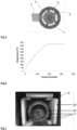
- FIG. 3 is a schematic representation of an indirect heating method, different from the invention.
- Panel A of the Figure 3 is a schematic representation in top view of the implementation of indirect heating.
- indirect heating involves the use of a first susceptor 3 and a sample 13 surrounded by the first susceptor 3.
- the material constituting the sample 13 to be heated is transparent to micro -wave 1 or microwave opaque 1.
- transparent we define a material whose dielectric and/or magnetic losses are substantially zero when the material is subjected to a microwave field 1 at a given frequency.
- a transparent material generally has very low electrical conductivity.
- the electrical conductivity of a transparent material can be less than 10 -8 Sm -1 , preferably less than 10 -10 Sm -1 and more preferably less than 10 -12 Sm -1 .
- an opaque material generally has a high electrical conductivity.
- the electrical conductivity of an opaque material is preferably greater than 10 3 Sm -1 .
- the interaction between the microwaves 1 and the sample 13 does not allow an increase in the temperature of the sample 13.
- the susceptor 3 placed around the sample 13 absorbs the microwaves 1 and emits infrared radiation 2. The sample can then be heated by infrared radiation 2.
- Panel B of the Figure 3 schematically illustrates a temperature profile along an axis passing through the center of the sample 13.
- the two temperature maxima of this implementation are located at the distance, corresponding to the axis d on the abscissa, from the location of the first susceptor 3.
- the temperature at the center of the sample is due to heating by infrared radiation 2 of the periphery of the sample coupled with thermal conduction within the sample as explained previously.
- the sample 13 is heated from the infrared radiation 2 of the first susceptor 3: it is then, for example, impossible to selectively heat a surface coating 5 to a temperature significantly higher than that of the metal part 4.
- this realization allows indirect heating of the sample. During this achievement, a significant part of the energy efficiency linked to microwave heating 1 is lost.
- FIG. 4 is a schematic representation of a different direct heating method of the invention.
- Panel A of the Figure 3 is a schematic representation in top view of the implementation of direct heating.
- the material constituting the sample 13 to be heated absorbs the microwaves 1 at a given frequency.
- the interaction between the microwaves 1 and the absorbent material of the sample 13 makes it possible to heat the sample.
- Panel B of the Figure 4 schematically illustrates a temperature profile along an axis passing through the center of the sample 13.
- the temperature profile has a maximum at the center of the sample.
- the profile may be different because it depends in particular on the size of the sample 13, the material of the sample 13, the power and the wavelength of the microwaves 1 emitted.
- FIG. 5 is a schematic representation of a hybrid heating method according to one embodiment of the invention.
- Panel A of the Figure 4 is a schematic representation in top view of the implementation of hybrid heating.
- the implementation of this embodiment of the invention comprises a sample 13 comprising a metal part 4, not visible in top view in the figure 5 , covered by a surface coating 5.
- the sample is surrounded by a first susceptor 3.
- the susceptor 3 absorbs the microwaves 1 at a given frequency.
- the microwave field 1 in the vicinity of sample 13 can then be partially screened.
- the susceptor emits infrared radiation 2 which contributes to the temperature treatment of the coating 5.
- the part of the microwaves 1 which is not screened in the vicinity of the sample 13 can be absorbed, at a frequency given, by the coating 5.
- This part of the microwaves 1 is, however, not absorbed by the part 4.
- the metallic nature of the part makes it opaque to microwave radiation 1.
- This hybrid method makes it possible to heat the coating by the contribution of infrared radiation and by the contribution of microwave radiation 1, without causing the formation of a plasma 14 in the vicinity of the metal part 4.
- FIG. 6 illustrates the kinetics of the temperature of the metal part 4 during heat treatment by microwave 1 according to the embodiment of the invention described in the figure 2 .
- Measuring the temperature of the Figure 6 is carried out by an infrared temperature sensor using the pyrometric sight 6 to capture the infrared spectrum of the coating 5.
- the heat treatment is carried out in two phases. During the first phase, a constant microwave emission power 1 is imposed (in this particular embodiment of the invention, the power of the microwave transmitter 1, during the first phase, is 6000 W) .
- the sample temperature increases to a set value of 425°C in less than 3 minutes. In a linear approximation of the temperature growth of the sample during this first phase, the slope of the kinetics is approximately 130°C.min -1 .
- the power is adjusted by the processing unit to maintain a constant temperature of 425°C (temperature level). This temperature is maintained for 2 minutes and 30 seconds.
- the kinetics does not include a temperature reduction ramp because the metal part 4 was removed from the microwave oven 1, as soon as the second phase was completed. Indeed, at the end of the stage, the microwave power 1 is stopped, thus allowing the opening of the cavity 9.
- FIG 7 is a photograph of a device used for implementing a method according to the invention.
- the device used comprises a receptacle 15 capable of containing one or more massive metal parts 4.
- the receptacle 15 is placed, at least in part, inside the first volume delimited by said first susceptor(s) 3.
- the receptacle 15 is a drum, made of pierced metal, surrounded by several first susceptors 3.
- the photograph of the figure 7 presents a device from which a first susceptor 3 (symbolized by black dotted lines) and a wall of a first thermal confinement 10 have been removed for the clarity of the illustration.
- the receptacle 15 can be set in motion in one embodiment of the method according to the invention, for example by means of a motor placed inside or outside the cavity 9.
- This setting in motion of the receptacle 15 is produced so as to agitate at least one massive metal part 4, placed inside the receptacle 15 during the process.
- the agitation of the room(s) massive metal 4 makes it possible to change the arrangement of said parts 4 with respect to the microwave field and/or the temperature distribution in the receptacle 15. If the microwave field and/or the spatial temperature distribution is not not homogeneous, this agitation can allow more homogeneous treatment of the different solid metal parts 4 and/or the coating of the different solid metal parts 4.
- the receptacle 15 can be a metal drum, as illustrated in the figure 7 .
- the drum is made of steel and drilled.
- a gas release can be caused by the heat treatment of the massive metal part(s) 4: the holes allow this release to be convected into the cavity 9 without being confined in the receptacle 15.
- the drum can rotate on itself to agitate the massive metal part(s) 4 it contains.
- the rotation can be carried out along an axis of symmetry of the drum.
- the agitation of the different massive metal parts 4 can be carried out during the emission of microwaves or between stages of microwave emission.
- a succession of steps of emitting microwaves and setting the receptacle 15 in motion can be advantageous: the agitation and bringing into contact of several massive metal parts 4 during the emission of microwaves can result in the creation of electric arcs between certain parts 4. This effect can be avoided by shaking the parts 4 while the microwave emission stops.
- the step of setting the receptacle 15 in motion can last a few seconds. This duration is small compared to the duration of a typical heat treatment (typically greater than 100 seconds) and only slightly disturbs the heat treatment of the parts 4.
- FIG. 8 is a set of photographs of a device used for implementing a method according to the invention.
- Panel A of the figure 8 is a photograph illustrating a set of third susceptors 16 integrally linked to the wall of a first thermal confinement 10.
- Panel B of the figure 8 is a photograph illustrating a device adapted to the implementation of a method according to the invention, comprising a plurality of third susceptors 16 arranged in the first volume delimited by the first susceptors 3.
- the visible parts of the third susceptors 16 in panel A of the figure 8 are, during the carrying out of the process, inserted into the volume of the receptacle 15, as illustrated by panel B of the figure 8 .
- a plurality of massive metal parts 4 is placed in the vicinity of at least a third susceptor 16. These parts 4 can be arranged both on a support and in a mobile receptacle 15. The inventors have discovered that this configuration results in faster kinetics of the temperature of the coating of the parts 4.
- six silicon carbide bars correspond to the third susceptors 16.
- the metal parts 4 can be arranged between or around these bars.
- the number and arrangement of the third susceptors 16 do not completely screen the microwave field: the heat treatment of the coating of the massive metal parts 4 results from a combination between the absorption of the microwaves by the coating(s) and the heat exchange from the susceptors to the coating(s).
Landscapes
- Chemical & Material Sciences (AREA)
- Organic Chemistry (AREA)
- Physics & Mathematics (AREA)
- Electromagnetism (AREA)
- Life Sciences & Earth Sciences (AREA)
- Engineering & Computer Science (AREA)
- Materials Engineering (AREA)
- Wood Science & Technology (AREA)
- Chemical Kinetics & Catalysis (AREA)
- Thermal Sciences (AREA)
- Health & Medical Sciences (AREA)
- Medicinal Chemistry (AREA)
- Polymers & Plastics (AREA)
- General Chemical & Material Sciences (AREA)
- Constitution Of High-Frequency Heating (AREA)
- Application Of Or Painting With Fluid Materials (AREA)
- Furnace Details (AREA)
Description
- L'invention concerne les dispositifs et les méthodes de traitement thermique de revêtement sur une pièce métallique.
- Les pièces ou substrats métalliques nécessitent des traitements de surface pour de nombreuses applications industrielles. Les métaux peuvent par exemple être traités pour obtenir des propriétés antiadhésives (lors d'une interaction avec des aliments, par des fluoropolymères), pour être résistants à différents types de corrosions (moisissure, salinité, oxydation, etc.), pour obtenir des propriétés mécaniques spécifiques, comme la résistance à différents types d'abrasions, ou encore pour être lubrifiés et ainsi réduire les frottements lors de la réalisation de systèmes métalliques dynamiques. Le document
US2005/221017 divulgue un dispositif de chauffage d'un revêtement d'une pièce métallique via une céramique sensible aux micro-ondes placées à côté de ce revêtement. Le documentDE102206010220 divulgue un procédé de soudage par micro-ondes pour fabriquer un échangeur thermique. - La réalisation de ces traitements de surface nécessite souvent un traitement thermique du revêtement sur la pièce métallique. C'est par exemple le cas des revêtements en fluoropolymères, et des revêtements époxy. On peut aussi envisager de recouvrir une pièce métallique d'un oxyde, souvent stables chimiquement et possédant des propriétés électriques, mécaniques ou optiques spécifiques. Cette méthode requiert souvent un traitement thermique dont la température est très élevée.
- Le traitement thermique des revêtements sur des pièces métalliques est réalisé dans l'art antérieur en chauffant la pièce par convection ou par induction. Dans le cas d'un chauffage par convection, un transfert thermique est établi entre une source de chaleur et l'échantillon à traiter au moyen d'une convection du milieu entourant l'échantillon. La source de chaleur est généralement une source émettant un rayonnement infrarouge, réalisée par exemple par un transducteur électrique, ou par la combustion d'un gaz. Dans le cas d'un chauffage par induction, des courants de Foucault chauffent la pièce métallique à traiter qui doit dans ce cas posséder préférentiellement des propriétés ferromagnétiques
- Les fours à micro-ondes peuvent présenter une alternative intéressante à ces deux méthodes de traitement thermique. Pour chauffer des matériaux non métalliques, ils présentent un rendement énergétique bien supérieur à celui des deux méthodes décrites précédemment, pouvant conduire à une économie significative de l'énergie utilisée dans le cas de fours à convection. Ce rendement peut s'expliquer par une absorption de l'énergie localisée au sein de l'échantillon et par la réduction du volume total à chauffer.
- Le chauffage d'un revêtement sur une pièce métallique massive et dense est, dans l'état de l'art, incompatible avec un chauffage micro-ondes. Dans un matériau, la longueur de pénétration d'un champ électromagnétique incident est inversement proportionnelle à la conductivité électrique du matériau. Ainsi, plus la conductivité électrique d'un matériau est élevée, plus il aura tendance à réfléchir des ondes électromagnétiques incidentes et en particulier des micro-ondes. Les métaux denses ont un comportement opaque et réfléchissant avec les micro-ondes, du fait de leur conductivité électrique élevée. Les réflexions du champ électromagnétique peuvent entraîner l'apparition d'un plasma lors d'un processus de chauffage d'un revêtement sur substrat métallique ou sur pièce métallique. Ces plasmas apparaissent lorsqu'assez d'énergie est apportée dans un gaz par exemple, en chauffant à haute température et en présentant un champ électromagnétique intense. Les formes d'une pièce métallique, telles que ses aspérités ou ses pointes (cas d'une pièce métallique de forme complexe) favorisent localement l'apparition d'un plasma.
- L'apparition d'un plasma a un effet dramatique sur le traitement thermique d'un revêtement de surface. Les plasmas comportent des particules chargées libres en volume et donc très conductrices. Un plasma réfléchit aussi un champ électromagnétique incident. Ce plasma peut entraîner une perturbation majeure du chauffage jusqu'à provoquer une baisse rapide et significative de la température de l'échantillon.
- Par ailleurs, les réflexions du champ électromagnétique sur des pièces métalliques denses et massives, dans des conditions de forte puissance d'émission micro-ondes, entraînent la formation potentielle d'un arc électrique dans une cavité micro-ondes. Cet effet est facilité par la présence d'aspérités et/ou de pointes sur le matériau massif. L'existence d'un tel arc peut être destructrice pour le dispositif de chauffage par micro-ondes.
- L'invention vise à surmonter au moins l'un des inconvénients précités de l'art antérieur.
- Un objet de l'invention permettant d'atteindre ce but est un procédé selon la revendication 1.
- Avantageusement, lesdits matériau, agencement et dimensions desdits premiers suscepteurs écrantent partiellement desdites micro-ondes à la fréquence ν0, au voisinage de chaque dite pièce métallique pendant la deuxième étape du procédé précédent.
- Avantageusement, ledit agencement dudit ou desdits premiers suscepteurs forme un premier volume délimité par ledit ou lesdits premiers suscepteurs et dans lequel la moyenne de l'intensité du champ électromagnétique émis pendant la deuxième étape du procédé précédent, à l'intérieur dudit premier volume est:
- supérieure à 1%, préférentiellement à 2% et préférentiellement à 5% de la moyenne de l'intensité du champ électromagnétique à l'extérieur dudit premier volume dans ladite cavité;
- inférieure à 90% et préférentiellement à 80% de la moyenne de l'intensité du champ électromagnétique à l'extérieur dudit premier volume dans ladite cavité.
- Avantageusement, ledit revêtement de surface présente une conductivité électrique inférieure à la conductivité électrique du matériau massif de chaque dite pièce métallique.
- Le procédé selon l'invention est un procédé de calcination d'un dit revêtement, ou un procédé de réticulation d'un dit revêtement.
- Avantageusement, le procédé précédent comprend également une étape consistant à mesurer, pendant au moins une partie de l'étape consistant à émettre les dites micro-ondes, la température dudit revêtement, puis à réguler la puissance d'émission desdites micro-ondes en fonction de ladite température mesurée.
- Avantageusement, le procédé précédent comprend également une étape consistant à placer ledit ou lesdits premiers suscepteurs et ladite ou lesdites pièces métalliques dans un premier confinement thermique.
- Avantageusement, le procédé précédent comprend également une étape consistant à entourer ledit premier confinement thermique par un ou une pluralité de seconds suscepteurs.
- Avantageusement, ledit agencement dudit ou desdits seconds suscepteurs forme un second volume délimité par ledit ou lesdits seconds suscepteurs et dans lequel la moyenne de l'intensité du champ électromagnétique émis pendant la deuxième étape du procédé précédent, à l'intérieur dudit premier volume est:
- supérieure à 1%, préférentiellement à 2% et préférentiellement à 5% de la moyenne de l'intensité du champ électromagnétique à l'extérieur dudit second volume dans ladite cavité et
- inférieure à 90% et préférentiellement à 80% de la moyenne de l'intensité du champ électromagnétique à l'extérieur dudit second volume dans ladite cavité.
- Avantageusement, le procédé précédent comprend également une étape consistant à placer ledit ou lesdits seconds suscepteurs et ledit premier confinement thermique dans un second confinement thermique.
- Avantageusement, le procédé comprend une étape consistant à mettre un réceptacle en mouvement, ledit réceptacle étant agencé au moins en partie à l'intérieur dudit premier volume délimité par ledit ou lesdits premiers suscepteurs, de manière à agiter au moins une dite pièce métallique massive à l'intérieur d'un réceptacle.
- Avantageusement, ledit réceptacle est un tambour apte à agiter au moins une dite pièce métallique massive par rotation.
- Avantageusement, le procédé comprend une étape consistant à placer une pluralité de dites pièces métalliques massives au voisinage d'au moins un troisième suscepteur agencé à l'intérieur dudit premier volume délimité par ledit ou lesdits premiers suscepteurs.
- Avantageusement, le matériau dudit ou desdits premiers ou seconds suscepteurs est choisi parmi un oxyde réfractaire et semi-conducteur d'un métal de transition, et un carbure.
- Avantageusement, le matériau dudit ou desdits premiers ou seconds suscepteurs est choisi parmi du carbure de silicium et de la chromite de lanthane.
- L'invention sera mieux comprise et d'autres avantages, détails et caractéristiques de celle-ci apparaîtront au cours de la description explicative qui suit, faite à titre d'exemple en référence aux dessins annexés dans lesquels :
- la
figure 1 est une photographie illustrant un problème technique du traitement thermique par micro-ondes dans un cas différent de l'art antérieur; - la
figure 2 est une représentation schématique de la coupe d'un dispositif utilisé pour la réalisation du procédé de l'invention; - la
figure 3 est une représentation schématique d'une méthode de chauffage indirect différente de l'invention ; - la
figure 4 est une représentation schématique d'une méthode de chauffage direct différente de l'invention ; - la
figure 5 est une représentation schématique d'une méthode de chauffage hybride selon un mode de réalisation de l'invention ; - la
figure 6 illustre la cinétique de la température de la pièce métallique 4 lors d'un traitement thermique par micro-ondes selon la réalisation de l'invention décrite dans lafigure 2 ; - la
figure 7 est une photographie d'un dispositif utilisé pour la mise en oeuvre d'un procédé selon l'invention ; - la
figure 8 est un ensemble de photographies d'un dispositif utilisé pour la mise en oeuvre d'un procédé selon l'invention. - La description suivante présente plusieurs exemples de réalisation du dispositif de l'invention : ces exemples sont non limitatifs de la portée de l'invention. Ces exemples de réalisation présentent à la fois les caractéristiques essentielles de l'invention ainsi que des caractéristiques additionnelles liées aux modes de réalisation considérés. Par souci de clarté, les mêmes éléments porteront les mêmes repères dans les différentes figures.
- La
figure 1 est une photographie illustrant un problème technique du traitement thermique par micro-ondes 1 dans un cas différent de l'art antérieur. Elle présente le traitement thermique d'un échantillon 13 en carbure de silicium (différent d'une pièce métallique massive 4) dans une cavité 9 dans laquelle des micro-ondes 1 sont émises, conduisant à une intensité du champ électromagnétique beaucoup plus élevée que dans les conditions de l'invention. Lors du traitement correspondant à la photographie, on observe la formation d'un plasma 14 sur un coin de l'échantillon 13. - Deux facteurs permettent principalement d'atteindre localement une quantité d'énergie favorable à l'initiation d'un plasma 14: la température et l'intensité du champ électromagnétique. Ces deux éléments sont favorisés lors du traitement photographié en
figure 1 d'un échantillon 13. Les aspérités de l'échantillon 13, ou sa forme, peuvent favoriser des effets de pointes. En chauffant et en émettant des micro-ondes 1, on peut créer localement des plasmas 14 sur des aspérités ou des pointes. Ce problème technique est largement amplifié lors du traitement d'une pièce métallique massive 4: la pièce 4 réfléchit les micro-ondes 1 et favorise la création de maxima de densité d'énergie locaux, entraînant la création d'un plasma 14 et empêchant le traitement thermique des échantillons métalliques. - La
figure 2 est une représentation schématique de la coupe d'un dispositif utilisé pour la réalisation du procédé de l'invention. Dans cette réalisation particulière de l'invention, la pièce métallique massive 4 possède un revêtement 5, déposé sur sa partie supérieure. La pièce métallique massive 4 est posée sur un support réalisé en isolant thermique 7. La pièce métallique 4 peut avoir des formes diverses : elle peut par exemple être un substrat cylindrique. La présence d'aspérités ou de pointes à sa surface est possible. Dans une réalisation particulière de l'invention, l'isolant thermique 7 peut être par exemple l'isolant thermique 7 liteCell (AET Technologies, isolant thermique à forte teneur en alumine). - La pièce métallique 4 est entourée d'un premier suscepteur 3, dont la coupe illustrant cette réalisation de l'invention fait apparaître deux tranches. Dans d'autres réalisations de l'invention, une pluralité de premiers suscepteurs 3 peuvent entourer la pièce métallique 4.
- Les dimensions, le matériau et l'agencement du ou des premiers suscepteurs 3 sont choisis, ou configurés, pour écranter, au moins partiellement, les micro-ondes à la fréquence ν0, au voisinage de chaque dite pièce métallique.
- Par l'utilisation du terme « au voisinage », on entend une longueur, inférieure à la longueur caractéristique d'une ou d'une pluralité de pièces métalliques 4.
- De manière générale, on considère par « micro-ondes » des ondes dont la fréquence est comprise entre 300 MHz et 300 GHz. En pratique, les micro-ondes seront avantageusement considérées comme des ondes dont la fréquence est comprise entre 900 MHz et 6 GHz.
- Un suscepteur est un matériau capable d'une excellente absorption du rayonnement des micro-ondes 1 à une fréquence donnée. Lors de l'absorption de ce rayonnement, le matériau suscepteur peut réémettre l'énergie absorbée par rayonnement infrarouge 2 par exemple. L'absorption d'un matériau suscepteur est gouvernée par des pertes diélectriques, électriques ou magnétiques élevées lors de l'excitation du matériau par un champ électromagnétique, comme par exemple dans le cas des micro-ondes 1. Les matériaux utilisés comme suscepteurs dans les réalisations de l'invention peuvent être du carbure de silicium (SiC), du chromite de lanthane (LaCrO3). D'autres matériaux à fortes capacités d'absorption des micro-ondes 1 peuvent être utilisés. On peut utiliser des matériaux comportant un oxyde réfractaire et semi-conducteur d'un métal de transition. On peut aussi utiliser les matériaux composés de carbures, comme le carbure de bore par exemple.
- L'absorption locale des micro-ondes 1 permet, selon l'agencement des différents suscepteurs, de configurer un volume dans lequel le champ électromagnétique est écranté.
- Dans cette réalisation de l'invention, l'ensemble formé par la pièce métallique 4 et son revêtement 5, le support en isolant thermique 7 et le premier suscepteur 3 entourant la pièce métallique 4, est entouré d'une paroi d'un premier confinement thermique 10 réalisé en isolant thermique 7. Dans une réalisation particulière de l'invention, l'isolant thermique 7 peut être par exemple l'isolant thermique 7 litecell (AET Technologies S.A.S., isolant thermique à forte teneur en alumine). Ce confinement par un isolant thermique 7 permet de limiter les pertes d'énergie par radiation pendant le traitement thermique.
- Dans la réalisation de l'invention présentée dans la
figure 2 , un ou une pluralité de seconds suscepteurs 12 sont placés autour du premier confinement thermique 10. L'ensemble composé des seconds suscepteurs 12 et du premier confinement thermique 10 est entouré par un second confinement thermique 11, réalisé en isolant thermique 7. Cette structure permet d'augmenter à la fois les propriétés de confinement thermique et de réduction locale du champ électromagnétique. Dans cette réalisation particulière de l'invention, le second confinement thermique 11 est réalisé par un isolant thermique 7 de type Quartzel (marque déposée, Saint-Gobain Quartz S.A.S.). - Dans la réalisation particulière présentée en
figure 2 , le second confinement thermique 11 est posé sur un plateau en aluminium. - L'ensemble des éléments décrits dans la
figure 2 est placé dans une cavité 9. Des micro-ondes 1 sont émises dans une entrée de la cavité 9 par un émetteur. Dans une réalisation particulière de l'invention, l'émetteur de micro-ondes 1 peut être un magnétron. Dans une réalisation particulière de l'invention, les micro-ondes 1 sont émises à la fréquence ν0 = 2,45 GHz. - La cavité 9, le premier confinement thermique 10, le second confinement thermique 11 et le second suscepteur 12 peuvent être percés afin de réaliser une visée pyrométrique 6. Cette visée 6 peut permettre à un capteur de température de mesurer à distance la température d'une pièce métallique 4 ou d'un revêtement 5 pendant un traitement thermique. Dans une réalisation particulière de l'invention, le capteur de température et l'émetteur de micro-ondes 1 sont reliés par l'intermédiaire d'un bus à une unité de traitement. L'unité de traitement comporte un ou plusieurs microprocesseurs et une mémoire. L'unité de traitement permet de contrôler de manière indépendante la puissance d'émission de l'émetteur micro-onde et de traiter les informations du capteur de température. Dans des réalisations particulières de l'invention, on asservit la puissance à une consigne de température donnée. La consigne de température peut être variable dans le temps de manière à réaliser des profils de traitement en température définis, comme des rampes de températures ou des traitements thermiques à température stationnaire.
- Lors de la réalisation du procédé de l'invention, la géométrie, l'agencement et les matériaux des premiers suscepteurs 3 entourant la pièce métallique massive 4 et permettant son écrantage, ont été trouvés par essais, successifs et itératifs. Ils peuvent également être approximés par une modélisation numérique utilisant la méthode des éléments finis.
- Dans une réalisation particulière de l'invention, l'écrantage d'une pièce métallique 4 peut être partiel. L'utilité d'un écrantage partiel d'une pièce métallique 4 est expliquée dans la description des figures suivantes. Dans des réalisations particulières de l'invention, l'agencement du ou des premiers suscepteurs 3 forme un volume délimité par le ou les premiers suscepteurs 3. La moyenne de l'intensité du champ électromagnétique lors de l'émission de micro-ondes 1 à l'intérieur du volume peut être :
- supérieure à 1%, préférentiellement à 2% et préférentiellement à 5% de la moyenne de l'intensité du champ électromagnétique à l'extérieur dudit volume dans la cavité 9 et
- inférieure à 90% et préférentiellement à 80% de la moyenne de l'intensité du champ électromagnétique à l'extérieur du volume dans la cavité 9.
- Dans une autre réalisation particulière de l'invention, l'écrantage partiel d'une pièce métallique 4 peut être réalisé par l'effet conjoint du ou des premiers suscepteurs 3 et du ou des seconds suscepteurs 12. Dans cette réalisation, l'agencement du ou des seconds suscepteurs 12 forme un volume délimité par le ou les seconds suscepteurs 12. La moyenne de l'intensité du champ électromagnétique lors de l'émission de micro-ondes 1 à l'intérieur du volume délimité précédemment par le ou les premier suscepteurs 3 peut être :
- supérieure à 1%, préférentiellement à 2% et préférentiellement à 5% de la moyenne de l'intensité du champ électromagnétique à l'extérieur du volume délimité par le ou les seconds suscepteurs 12 dans la cavité 9 et
- inférieure à 90% et préférentiellement à 80% de la moyenne de l'intensité du champ électromagnétique à l'extérieur du volume délimité par le ou les seconds suscepteurs 12 dans la cavité 9.
- La
figure 3 est une représentation schématique d'une méthode de chauffage indirect, différente de l'invention. Le panneau A de lafigure 3 est une représentation schématique en vue de dessus de la mise en oeuvre d'un chauffage indirect. - La mise en oeuvre du chauffage indirect comporte l'utilisation d'un premier suscepteur 3 et d'un échantillon 13 entouré par le premier suscepteur 3. Dans le cas du chauffage indirect, le matériau constituant l'échantillon 13 à chauffer est transparent aux micro-ondes 1 ou opaque aux micro-ondes 1.
- Par « transparent », on définit un matériau dont les pertes diélectriques et/ou magnétiques sont sensiblement nulles lorsque le matériau est soumis à un champ micro-ondes 1 à une fréquence donnée. Un matériau transparent possède généralement une conductivité électrique très faible. La conductivité électrique d'un matériau transparent peut être inférieure à 10-8 S.m-1, préférentiellement inférieure à 10-10 S.m-1 et plus préférentiellement inférieure à 10-12 S.m-1.
- Par « opaque », on définit un matériau réfléchissant le rayonnement des micro-ondes 1 pour une fréquence donnée. Un matériau opaque possède en général une conductivité électrique élevée. La conductivité électrique d'un matériau opaque est préférentiellement supérieure à 103 S.m-1. Dans cette mise en oeuvre différente de celle de l'invention, l'interaction entre les micro-ondes 1 et l'échantillon 13 ne permet pas une croissance de la température de l'échantillon 13. En revanche, le suscepteur 3 placé autour de l'échantillon 13 absorbe les micro-ondes 1 et émet un rayonnement infrarouge 2. L'échantillon peut alors être chauffé par un rayonnement infrarouge 2.
- Le panneau B de la
figure 3 illustre schématiquement un profil de température suivant un axe passant par le centre de l'échantillon 13. Les deux maxima de température de cette mise en oeuvre se situent à la distance, correspondant à l'axe d en abscisse, de l'emplacement du premier suscepteur 3. La température au centre de l'échantillon est due à un chauffage par rayonnement infrarouge 2 de la périphérie de l'échantillon couplé à une conduction thermique au sein de l'échantillon comme expliqué précédemment. - Cette mise en oeuvre ne permet par de résoudre le problème technique posé par l'art antérieur. D'une part, l'échantillon 13 est chauffé à partir du rayonnement infrarouge 2 du premier suscepteur 3 : il est alors par exemple impossible de chauffer sélectivement un revêtement 5 de surface à une température sensiblement supérieure à celle de la pièce métallique 4. D'autre part, cette réalisation permet un chauffage indirect de l'échantillon. Lors de cette réalisation, on perd une partie significative du rendement énergétique liée au chauffage par micro-ondes 1.
- La
figure 4 est une représentation schématique d'une méthode de chauffage direct différente de l'invention. Le panneau A de lafigure 3 est une représentation schématique en vue de dessus de la mise en oeuvre d'un chauffage direct. Dans le cas du chauffage direct, le matériau constituant l'échantillon 13 à chauffer absorbe les micro-ondes 1 à une fréquence donnée. L'interaction entre les micro-ondes 1 et le matériau absorbant de l'échantillon 13 permet de chauffer l'échantillon. - Le panneau B de la
figure 4 illustre schématiquement un profil de température suivant un axe passant par le centre de l'échantillon 13. Dans cette mise en oeuvre, différente de l'invention, le profil de température présente un maximum au centre de l'échantillon. Le profil peut être différent car il dépend notamment de la taille de l'échantillon 13, du matériau de l'échantillon 13, de la puissance et de la longueur d'onde des micro-ondes 1 émises. - Cette mise en oeuvre ne permet par de résoudre le problème technique posé par l'art antérieur. Dans le cas d'un échantillon 13 comportant une pièce métallique massive 4 et son revêtement de surface 5, la puissance des micro-ondes 1 émises nécessaire au traitement thermique du revêtement 5 de surface peut entraîner l'apparition d'un plasma 14 au voisinage de l'échantillon 13 et/ou d'un arc électrique dans la cavité 9.
- La
figure 5 est une représentation schématique d'une méthode de chauffage hybride selon un mode de réalisation de l'invention. Le panneau A de lafigure 4 est une représentation schématique en vue de dessus de la mise en oeuvre d'un chauffage hybride. La mise en oeuvre de cette réalisation de l'invention comporte un échantillon 13 comprenant une pièce métallique 4, non visible en vue de dessus dans lafigure 5 , couverte par un revêtement de surface 5. L'échantillon est entouré par un premier suscepteur 3. Dans cette réalisation de l'invention, le suscepteur 3 absorbe à une fréquence donnée les micro-ondes 1. Le champ micro-onde 1 au voisinage de l'échantillon 13 peut alors être écranté partiellement. Le suscepteur émet dans ce cas un rayonnement infrarouge 2 qui contribue au traitement en température du revêtement 5. En outre, la partie des micro-ondes 1 qui n'est pas écrantée au voisinage de l'échantillon 13 peut être absorbée, à une fréquence donnée, par le revêtement 5. Cette partie des micro-ondes 1 n'est en revanche pas absorbée par la pièce 4. En effet, le caractère métallique de la pièce la rend opaque au rayonnement micro-ondes 1. Cette méthode hybride permet de chauffer le revêtement par la contribution du rayonnement infrarouge et par la contribution du rayonnement micro-ondes 1, sans entraîner la formation d'un plasma 14 au voisinage de la pièce métallique 4. - La
figure 6 illustre la cinétique de la température de la pièce métallique 4 lors d'un traitement thermique par micro-ondes 1 selon la réalisation de l'invention décrite dans lafigure 2 . La mesure de la température de lafigure 6 est réalisée par un capteur de température infrarouge utilisant la visée pyrométrique 6 pour capter le spectre infrarouge du revêtement 5. Le traitement thermique est réalisé en deux phases. Lors de la première phase, on impose une puissance constante d'émission micro-ondes 1 (dans cette réalisation particulière de l'invention, la puissance de l'émetteur micro-ondes 1, lors de la première phase, est de 6000 W). La température de l'échantillon croît jusqu'à une valeur consigne de 425 °C en moins de 3 minutes. Dans une approximation linéaire de la croissance de température de l'échantillon lors de cette première phase, la pente de la cinétique est d'environ 130°C.min-1. Lors de la seconde phase, la puissance est ajustée par l'unité de traitement pour maintenir une température de 425°C constante (palier de température). Cette température est maintenue pendant 2 minutes et 30 secondes. La cinétique ne comporte pas de rampe de descente en température car la pièce métallique 4 a été retirée du four micro-ondes 1, dès la deuxième phase terminée. En effet, dès la fin du palier, la puissance micro-ondes 1 est arrêtée, permettant ainsi l'ouverture de la cavité 9. - La
figure 7 est une photographie d'un dispositif utilisé pour la mise en oeuvre d'un procédé selon l'invention. Le dispositif utilisé comporte un réceptacle 15 apte à contenir une ou des pièces métalliques massives 4. Le réceptacle 15 est placé, au moins en partie, à l'intérieur du premier volume délimité par ledit ou lesdits premiers suscepteurs 3. Dans l'exemple illustré enfigure 7 , le réceptacle 15 est un tambour, en métal percé, entouré de plusieurs premiers suscepteurs 3. La photographie de lafigure 7 présente un dispositif dont on a enlevé un premier suscepteur 3 (symbolisé par des pointillés noirs) et une paroi d'un premier confinement thermique 10 pour la clarté de l'illustration. - Le réceptacle 15 peut être mis en mouvement dans un mode de réalisation du procédé selon l'invention, par exemple au moyen d'un moteur placé à l'intérieur ou à l'extérieur de la cavité 9. Cette mise en mouvement du réceptacle 15 est réalisée de manière à agiter au moins une pièce métallique massive 4, placée à l'intérieur du réceptacle 15 lors du procédé. L'agitation de la ou des pièces métalliques massives 4 permet de changer l'agencement des dites pièces 4 par rapport au champ micro-ondes et/ou à la distribution de température dans le réceptacle 15. Si le champ micro-ondes et/ou la distribution spatiale de température n'est pas homogène, cette agitation peut permettre un traitement plus homogène des différentes pièces métalliques massives 4 et/ou du revêtement des différentes pièces métalliques massives 4.
- Le réceptacle 15 peut être un tambour métallique, comme illustré dans la
figure 7 . Dans cet exemple, le tambour est réalisé en acier et percé. Un dégagement gazeux peut être entraîné par le traitement thermique de la ou des pièces métalliques massives 4: les trous permettent à ce dégagement d'être convecté dans la cavité 9 sans être confiné dans le réceptacle 15. - Le tambour peut réaliser une rotation sur lui-même pour agiter la ou les pièces métalliques massives 4 qu'il contient. La rotation peut être réalisée selon un axe de symétrie du tambour.
- L'agitation des différentes pièces métalliques massives 4 peut être réalisée pendant l'émission des micro-ondes ou bien entre des étapes d'émission de micro-ondes. Une succession des étapes d'émission des micro-ondes et de mise en mouvement du réceptacle 15 peut être avantageuse : l'agitation et la mise en contact de plusieurs pièces métalliques massives 4 pendant l'émission de micro-ondes peut entraîner la création d'arcs électriques entre certaines pièces 4. Cet effet peut être évité en agitant les pièces 4 pendant un arrêt de l'émission de micro-ondes. L'étape de mise en mouvement du réceptacle 15 peut durer quelques secondes. Cette durée est petite devant la durée d'un traitement thermique typique (typiquement supérieur à 100 secondes) et ne perturbe que faiblement le traitement thermique des pièces 4.
- La
figure 8 est un ensemble de photographies d'un dispositif utilisé pour la mise en oeuvre d'un procédé selon l'invention. Le panneau A de lafigure 8 est une photographie illustrant un ensemble de troisièmes suscepteurs 16 liés de manière solidaire à la paroi d'un premier confinement thermique 10. Le panneau B de lafigure 8 est une photographie illustrant un dispositif adapté à la mise en oeuvre d'un procédé selon l'invention, comportant une pluralité de troisièmes suscepteurs 16 agencée dans le premier volume délimité par les premiers suscepteurs 3. Les parties visibles des troisièmes suscepteurs 16 dans le panneau A de lafigure 8 , sont, pendant la réalisation du procédé, insérées dans le volume du réceptacle 15, comme illustré par le panneau B de lafigure 8 . De manière plus générale, une pluralité de pièces métalliques massives 4 est placée au voisinage d'au moins un troisième suscepteur 16. Ces pièces 4 peuvent être disposées aussi bien sur un support que dans un réceptacle 15 mobile. Les inventeurs ont découvert que cette configuration entraîne une cinétique de la température du revêtement des pièces 4 plus rapide. Dans la configuration du dispositif illustré dans le panneau B de lafigure 8 , six barreaux en carbure de silicium correspondent aux troisièmes suscepteurs 16. Pendant le procédé, les pièces métalliques 4 peuvent être disposées entre ou autours de ces barreaux. Le nombre et la disposition des troisièmes suscepteurs 16 n'écrantent pas totalement le champ micro-ondes : le traitement thermique du revêtement des pièces métalliques massives 4 résulte d'une combinaison entre l'absorption des micro-ondes par le ou les revêtements et l'échange thermique des suscepteurs vers le ou les revêtements.
Claims (14)
- Procédé de traitement d'un revêtement de surface (5) d'une pièce métallique massive (4), comprenant les étapes consistant à :• placer dans une cavité micro-ondes (9) au moins une dite pièce métallique (4) comportant un dit revêtement de surface (5) pouvant absorber des micro-ondes (1) à la fréquence ν0, entourée d'un ou d'une pluralité de premiers suscepteurs (3) dont les dimensions, le matériau et l'agencement sont configurés pour écranter desdites micro-ondes (1) à la fréquence ν0, au voisinage de chaque dite pièce métallique (4) ;• émettre desdites micro-ondes à la fréquence ν0 dans ladite cavité micro-ondes ;
dans lequel le procédé de traitement du revêtement (5) est un procédé de calcination ou dans lequel le procédé de traitement du revêtement (5) est un procédé de réticulation. - Procédé selon la revendication précédente dans lequel lesdits matériaux, agencement et dimensions desdits premiers suscepteurs (3) écrantent partiellement desdites micro-ondes (1) à la fréquence ν0, au voisinage de chaque dite pièce métallique (4) pendant la deuxième étape de la revendication précédente.
- Procédé selon la revendication précédente dans lequel ledit agencement dudit ou desdits premiers suscepteurs (3) forme un premier volume délimité par ledit ou lesdits premiers suscepteurs (3) et dans lequel la moyenne de l'intensité du champ électromagnétique émis pendant la deuxième étape de la revendication 1, à l'intérieur dudit premier volume est:• supérieure à 1 %, préférentiellement à 2% et préférentiellement à 5% de la moyenne de l'intensité du champ électromagnétique à l'extérieur dudit premier volume dans ladite cavité micro-ondes (9) et• inférieure à 90% et préférentiellement à 80% de la moyenne de l'intensité du champ électromagnétique à l'extérieur dudit premier volume dans ladite cavité micro-ondes (9).
- Procédé selon les revendications précédentes dans lequel ledit revêtement de surface (5) présente une conductivité électrique inférieure à la conductivité électrique du matériau massif de chaque dite pièce métallique (4).
- Procédé selon l'une des revendications précédentes comportant également une étape consistant à mesurer, pendant au moins une partie de l'étape consistant à émettre les dites micro-ondes (1), la température dudit revêtement (5), puis à réguler la puissance d'émission desdites micro-ondes (1) en fonction de ladite température mesurée.
- Procédé selon l'une des revendications précédentes, comprenant une étape consistant à placer ledit ou lesdits premiers suscepteurs (3) et ladite ou lesdites pièces métalliques (4) dans un premier confinement thermique (10).
- Procédé selon la revendication 6, comprenant une étape consistant à entourer ledit premier confinement thermique (10) par un ou une pluralité de seconds suscepteurs (12).
- Procédé selon la revendication 7 dans lequel ledit agencement dudit ou desdits seconds suscepteurs (12) forme un second volume délimité par ledit ou lesdits seconds suscepteurs (12) et dans lequel la moyenne de l'intensité du champ électromagnétique émis pendant la deuxième étape de la revendication 1, à l'intérieur dudit premier volume est:• supérieure à 1%, préférentiellement à 2% et préférentiellement à 5% de la moyenne de l'intensité du champ électromagnétique à l'extérieur dudit second volume dans ladite cavité micro-ondes (9) et• inférieure à 90% et préférentiellement à 80% de la moyenne de l'intensité du champ électromagnétique à l'extérieur dudit second volume dans ladite cavité micro-ondes (9).
- Procédé selon la revendication 7 à 8, comprenant une étape consistant à placer ledit ou lesdits seconds suscepteurs (12) et ledit premier confinement thermique (10) dans un second confinement thermique (11).
- Procédé selon l'une des revendications précédentes comprenant une étape consistant à mettre un réceptacle (15) en mouvement, ledit réceptacle étant agencé au moins en partie à l'intérieur dudit premier volume délimité par ledit ou lesdits premiers suscepteurs (3), de manière à agiter au moins une dite pièce métallique massive (4) à l'intérieur d'un réceptacle (15).
- Procédé selon la revendication 10 dans lequel ledit réceptacle (15) est un tambour apte à agiter au moins une dite pièce métallique massive (4) par rotation.
- Procédé selon l'une des revendications précédentes comportant une étape consistant à placer une pluralité de dites pièces métalliques massives (4) au voisinage d'au moins un troisième suscepteur (16) agencé à l'intérieur dudit premier volume délimité par ledit ou lesdits premiers suscepteurs (3).
- Procédé selon l'une des revendications 1 à 12 dans lequel le matériau dudit ou desdits premiers, seconds ou troisièmes suscepteurs (3,12) est choisi parmi un oxyde réfractaire et semi-conducteur d'un métal de transition, et un carbure.
- Procédé selon l'une des revendications 1 à 12 dans lequel le matériau dudit ou desdits premiers, seconds ou troisièmes suscepteurs (3,12) est choisi parmi du carbure de silicium et de la chromite de lanthane.
Applications Claiming Priority (2)
| Application Number | Priority Date | Filing Date | Title |
|---|---|---|---|
| FR1552629 | 2015-03-27 | ||
| PCT/EP2016/056737 WO2016156275A1 (fr) | 2015-03-27 | 2016-03-25 | Procédé de traitement thermique de revêtement de surface sur une pièce métallique par micro-ondes |
Publications (2)
| Publication Number | Publication Date |
|---|---|
| EP3274103A1 EP3274103A1 (fr) | 2018-01-31 |
| EP3274103B1 true EP3274103B1 (fr) | 2024-07-31 |
Family
ID=53200169
Family Applications (1)
| Application Number | Title | Priority Date | Filing Date |
|---|---|---|---|
| EP16713392.5A Active EP3274103B1 (fr) | 2015-03-27 | 2016-03-25 | Procédé de traitement thermique de revêtement de surface sur une pièce métallique par micro-ondes |
Country Status (4)
| Country | Link |
|---|---|
| US (1) | US10882071B2 (fr) |
| EP (1) | EP3274103B1 (fr) |
| JP (1) | JP6764926B2 (fr) |
| WO (1) | WO2016156275A1 (fr) |
Families Citing this family (4)
| Publication number | Priority date | Publication date | Assignee | Title |
|---|---|---|---|---|
| CN108430127B (zh) * | 2017-02-15 | 2020-10-30 | 合默麟机械股份有限公司 | 腔体可分离的模块化复合微波加热系统 |
| FR3064001B1 (fr) | 2017-03-17 | 2021-08-06 | Association Pour La Rech Et Le Developpement Des Methodes Et Processus Industriels Armines | Equipement de cuisson de preformes en ceramiques necessitant une grande precision |
| FR3099408B1 (fr) * | 2019-07-30 | 2021-07-09 | Optiwaves | Creuset pour traitement thermique hautes températures de pièces massives |
| AT523061B1 (de) * | 2019-10-16 | 2021-05-15 | Ess Holding Gmbh | Verfahren zur Oberflächenbeschichtung von Werkstücken |
Citations (1)
| Publication number | Priority date | Publication date | Assignee | Title |
|---|---|---|---|---|
| DE102006010220A1 (de) * | 2005-03-09 | 2006-09-14 | Denso Corp., Kariya | Herstellungsverfahren, Lötvorrichtung und Metallgegenstand |
Family Cites Families (12)
| Publication number | Priority date | Publication date | Assignee | Title |
|---|---|---|---|---|
| JPS5839358Y2 (ja) * | 1979-06-26 | 1983-09-05 | 三菱電機株式会社 | マイクロ波加熱炉 |
| US4307277A (en) * | 1978-08-03 | 1981-12-22 | Mitsubishi Denki Kabushiki Kaisha | Microwave heating oven |
| US4876423A (en) | 1988-05-16 | 1989-10-24 | Dennison Manufacturing Company | Localized microwave radiation heating |
| DE19700141A1 (de) * | 1997-01-04 | 1998-07-09 | Gero Hochtemperaturoefen Gmbh | Brennofen für die Hochtemperaturbehandlung von Materialien mit niedrigem dielektrischem Verlustfaktor |
| JP4214040B2 (ja) * | 2003-07-22 | 2009-01-28 | 高砂工業株式会社 | マイクロ波加熱炉の操業方法及びマイクロ波加熱炉 |
| US20050221017A1 (en) | 2004-03-30 | 2005-10-06 | Vladislav Sklyarevich | Method of heat treating coatings by using microwave |
| JP4005049B2 (ja) * | 2004-04-16 | 2007-11-07 | 松下電器産業株式会社 | マイクロ波焼成炉 |
| US20090079101A1 (en) * | 2007-04-27 | 2009-03-26 | Jurgen Laubersheimer | Densification Process of Ceramics And Apparatus Therefor |
| JP2010025452A (ja) * | 2008-07-19 | 2010-02-04 | Ivoclar Vivadent Ag | セラミックスの緻密化方法およびそのための装置 |
| DE102008035235B4 (de) * | 2008-07-29 | 2014-05-22 | Ivoclar Vivadent Ag | Vorrichtung zur Erwärmung von Formteilen, insbesondere dentalkeramischen Formteilen |
| EP2437020B1 (fr) | 2010-10-01 | 2015-08-12 | Ivoclar Vivadent AG | Four à micro-ondes |
| US9636705B2 (en) * | 2012-07-12 | 2017-05-02 | Tata Steel Uk Limited | Microwave curing of multi-layer coatings |
-
2016
- 2016-03-25 US US15/561,884 patent/US10882071B2/en active Active
- 2016-03-25 WO PCT/EP2016/056737 patent/WO2016156275A1/fr not_active Ceased
- 2016-03-25 EP EP16713392.5A patent/EP3274103B1/fr active Active
- 2016-03-25 JP JP2018500865A patent/JP6764926B2/ja not_active Expired - Fee Related
Patent Citations (1)
| Publication number | Priority date | Publication date | Assignee | Title |
|---|---|---|---|---|
| DE102006010220A1 (de) * | 2005-03-09 | 2006-09-14 | Denso Corp., Kariya | Herstellungsverfahren, Lötvorrichtung und Metallgegenstand |
Also Published As
| Publication number | Publication date |
|---|---|
| JP2018518365A (ja) | 2018-07-12 |
| US20180111157A1 (en) | 2018-04-26 |
| WO2016156275A1 (fr) | 2016-10-06 |
| US10882071B2 (en) | 2021-01-05 |
| JP6764926B2 (ja) | 2020-10-07 |
| EP3274103A1 (fr) | 2018-01-31 |
Similar Documents
| Publication | Publication Date | Title |
|---|---|---|
| EP3274103A1 (fr) | Procédé de traitement thermique de revêtement de surface sur une pièce métallique par micro-ondes | |
| EP0713351B1 (fr) | Foyer de cuisson à induction | |
| Tan et al. | Induction sintering of silver nanoparticle inks on polyimide substrates | |
| WO2005094127A1 (fr) | Procede pour chauffer des materiaux en vue de produire des objets et dispositif mettant en oeuvre ce procede | |
| CA3004391C (fr) | Dispositif de generation d'une microstructure a gradient de structure sur une piece axisymetrique | |
| FR2937148A1 (fr) | Detecteur a scintillation protege thermiquement | |
| FR2704942A1 (fr) | Four micro-ondes en particulier pour chauffage rapide à haute température. | |
| WO2009117745A2 (fr) | Traitement de préchauffage de surface de substrat en plastique | |
| Rawat et al. | Comparative performance of various susceptor materials and vertical cavity shapes for selective microwave hybrid heating (SMHH) | |
| WO2011055043A2 (fr) | Ustensile de cuisson en ceramique | |
| WO2018077735A1 (fr) | Procede de traitement thermique d'une piece en materiau ceramique par micro-ondes | |
| WO2018167397A1 (fr) | Équipement de cuisson de préformes en céramiques necessitant une grande précision | |
| CH620289A5 (fr) | ||
| EP2758553B1 (fr) | Dispositif et procede de chauffage d'un objet sous un champ magnetique intense | |
| WO2021019187A1 (fr) | Creuset pour traitement thermique hautes temperatures de pieces massives | |
| EP3272186A1 (fr) | Système de test comprenant un dispositif de chauffage et procédé de mise en oeuvre d'un système de test | |
| Zare et al. | Measurement of near-field thermal emission spectra using an internal reflection element | |
| WO2020212168A1 (fr) | Installation de densification cvi | |
| Calame et al. | Narrowband Microwave Dielectric Resonance and Negative Permittivity Behavior in Hydrogen‐Fired Al2O3–CuO Composites | |
| EP3005833B1 (fr) | Dispositif de traitement thermique de produits par micro-ondes et procédé de traitement thermique mettant en oeuvre un tel dispositif | |
| EP2874524A1 (fr) | Article, ensemble et systeme culinaire a detection de composes volatils, et un procede de realisation de l'article culinaire | |
| FR2836592A1 (fr) | Resistor en materiau carbone | |
| FR3072894A1 (fr) | Procede de controle des dimensions d’une piece frittable au cours de son frittage | |
| EP3940328A1 (fr) | Systeme de traitement thermique de materiaux elabores par metallurgie des poudres | |
| BE631875A (fr) |
Legal Events
| Date | Code | Title | Description |
|---|---|---|---|
| STAA | Information on the status of an ep patent application or granted ep patent |
Free format text: STATUS: THE INTERNATIONAL PUBLICATION HAS BEEN MADE |
|
| PUAI | Public reference made under article 153(3) epc to a published international application that has entered the european phase |
Free format text: ORIGINAL CODE: 0009012 |
|
| STAA | Information on the status of an ep patent application or granted ep patent |
Free format text: STATUS: REQUEST FOR EXAMINATION WAS MADE |
|
| 17P | Request for examination filed |
Effective date: 20170927 |
|
| AK | Designated contracting states |
Kind code of ref document: A1 Designated state(s): AL AT BE BG CH CY CZ DE DK EE ES FI FR GB GR HR HU IE IS IT LI LT LU LV MC MK MT NL NO PL PT RO RS SE SI SK SM TR |
|
| AX | Request for extension of the european patent |
Extension state: BA ME |
|
| DAV | Request for validation of the european patent (deleted) | ||
| DAX | Request for extension of the european patent (deleted) | ||
| STAA | Information on the status of an ep patent application or granted ep patent |
Free format text: STATUS: EXAMINATION IS IN PROGRESS |
|
| 17Q | First examination report despatched |
Effective date: 20190412 |
|
| GRAP | Despatch of communication of intention to grant a patent |
Free format text: ORIGINAL CODE: EPIDOSNIGR1 |
|
| STAA | Information on the status of an ep patent application or granted ep patent |
Free format text: STATUS: GRANT OF PATENT IS INTENDED |
|
| RIC1 | Information provided on ipc code assigned before grant |
Ipc: H05B 6/80 20060101ALI20240201BHEP Ipc: H05B 6/64 20060101ALI20240201BHEP Ipc: B05D 3/02 20060101AFI20240201BHEP |
|
| INTG | Intention to grant announced |
Effective date: 20240306 |
|
| GRAS | Grant fee paid |
Free format text: ORIGINAL CODE: EPIDOSNIGR3 |
|
| GRAA | (expected) grant |
Free format text: ORIGINAL CODE: 0009210 |
|
| STAA | Information on the status of an ep patent application or granted ep patent |
Free format text: STATUS: THE PATENT HAS BEEN GRANTED |
|
| AK | Designated contracting states |
Kind code of ref document: B1 Designated state(s): AL AT BE BG CH CY CZ DE DK EE ES FI FR GB GR HR HU IE IS IT LI LT LU LV MC MK MT NL NO PL PT RO RS SE SI SK SM TR |
|
| REG | Reference to a national code |
Ref country code: CH Ref legal event code: EP Ref country code: GB Ref legal event code: FG4D Free format text: NOT ENGLISH |
|
| REG | Reference to a national code |
Ref country code: DE Ref legal event code: R096 Ref document number: 602016088645 Country of ref document: DE |
|
| REG | Reference to a national code |
Ref country code: IE Ref legal event code: FG4D Free format text: LANGUAGE OF EP DOCUMENT: FRENCH |
|
| REG | Reference to a national code |
Ref country code: LT Ref legal event code: MG9D |
|
| REG | Reference to a national code |
Ref country code: NL Ref legal event code: MP Effective date: 20240731 |
|
| PG25 | Lapsed in a contracting state [announced via postgrant information from national office to epo] |
Ref country code: PT Free format text: LAPSE BECAUSE OF FAILURE TO SUBMIT A TRANSLATION OF THE DESCRIPTION OR TO PAY THE FEE WITHIN THE PRESCRIBED TIME-LIMIT Effective date: 20241202 |
|
| REG | Reference to a national code |
Ref country code: AT Ref legal event code: MK05 Ref document number: 1707989 Country of ref document: AT Kind code of ref document: T Effective date: 20240731 |
|
| PG25 | Lapsed in a contracting state [announced via postgrant information from national office to epo] |
Ref country code: PT Free format text: LAPSE BECAUSE OF FAILURE TO SUBMIT A TRANSLATION OF THE DESCRIPTION OR TO PAY THE FEE WITHIN THE PRESCRIBED TIME-LIMIT Effective date: 20241202 |
|
| PG25 | Lapsed in a contracting state [announced via postgrant information from national office to epo] |
Ref country code: NO Free format text: LAPSE BECAUSE OF FAILURE TO SUBMIT A TRANSLATION OF THE DESCRIPTION OR TO PAY THE FEE WITHIN THE PRESCRIBED TIME-LIMIT Effective date: 20241031 |
|
| PG25 | Lapsed in a contracting state [announced via postgrant information from national office to epo] |
Ref country code: PL Free format text: LAPSE BECAUSE OF FAILURE TO SUBMIT A TRANSLATION OF THE DESCRIPTION OR TO PAY THE FEE WITHIN THE PRESCRIBED TIME-LIMIT Effective date: 20240731 Ref country code: FI Free format text: LAPSE BECAUSE OF FAILURE TO SUBMIT A TRANSLATION OF THE DESCRIPTION OR TO PAY THE FEE WITHIN THE PRESCRIBED TIME-LIMIT Effective date: 20240731 Ref country code: NL Free format text: LAPSE BECAUSE OF FAILURE TO SUBMIT A TRANSLATION OF THE DESCRIPTION OR TO PAY THE FEE WITHIN THE PRESCRIBED TIME-LIMIT Effective date: 20240731 Ref country code: GR Free format text: LAPSE BECAUSE OF FAILURE TO SUBMIT A TRANSLATION OF THE DESCRIPTION OR TO PAY THE FEE WITHIN THE PRESCRIBED TIME-LIMIT Effective date: 20241101 |
|
| PG25 | Lapsed in a contracting state [announced via postgrant information from national office to epo] |
Ref country code: BG Free format text: LAPSE BECAUSE OF FAILURE TO SUBMIT A TRANSLATION OF THE DESCRIPTION OR TO PAY THE FEE WITHIN THE PRESCRIBED TIME-LIMIT Effective date: 20240731 |
|
| PG25 | Lapsed in a contracting state [announced via postgrant information from national office to epo] |
Ref country code: LV Free format text: LAPSE BECAUSE OF FAILURE TO SUBMIT A TRANSLATION OF THE DESCRIPTION OR TO PAY THE FEE WITHIN THE PRESCRIBED TIME-LIMIT Effective date: 20240731 |
|
| PG25 | Lapsed in a contracting state [announced via postgrant information from national office to epo] |
Ref country code: IS Free format text: LAPSE BECAUSE OF FAILURE TO SUBMIT A TRANSLATION OF THE DESCRIPTION OR TO PAY THE FEE WITHIN THE PRESCRIBED TIME-LIMIT Effective date: 20241130 Ref country code: AT Free format text: LAPSE BECAUSE OF FAILURE TO SUBMIT A TRANSLATION OF THE DESCRIPTION OR TO PAY THE FEE WITHIN THE PRESCRIBED TIME-LIMIT Effective date: 20240731 |
|
| PG25 | Lapsed in a contracting state [announced via postgrant information from national office to epo] |
Ref country code: HR Free format text: LAPSE BECAUSE OF FAILURE TO SUBMIT A TRANSLATION OF THE DESCRIPTION OR TO PAY THE FEE WITHIN THE PRESCRIBED TIME-LIMIT Effective date: 20240731 |
|
| PG25 | Lapsed in a contracting state [announced via postgrant information from national office to epo] |
Ref country code: RS Free format text: LAPSE BECAUSE OF FAILURE TO SUBMIT A TRANSLATION OF THE DESCRIPTION OR TO PAY THE FEE WITHIN THE PRESCRIBED TIME-LIMIT Effective date: 20241031 Ref country code: ES Free format text: LAPSE BECAUSE OF FAILURE TO SUBMIT A TRANSLATION OF THE DESCRIPTION OR TO PAY THE FEE WITHIN THE PRESCRIBED TIME-LIMIT Effective date: 20240731 |
|
| PG25 | Lapsed in a contracting state [announced via postgrant information from national office to epo] |
Ref country code: RS Free format text: LAPSE BECAUSE OF FAILURE TO SUBMIT A TRANSLATION OF THE DESCRIPTION OR TO PAY THE FEE WITHIN THE PRESCRIBED TIME-LIMIT Effective date: 20241031 Ref country code: PL Free format text: LAPSE BECAUSE OF FAILURE TO SUBMIT A TRANSLATION OF THE DESCRIPTION OR TO PAY THE FEE WITHIN THE PRESCRIBED TIME-LIMIT Effective date: 20240731 Ref country code: NO Free format text: LAPSE BECAUSE OF FAILURE TO SUBMIT A TRANSLATION OF THE DESCRIPTION OR TO PAY THE FEE WITHIN THE PRESCRIBED TIME-LIMIT Effective date: 20241031 Ref country code: NL Free format text: LAPSE BECAUSE OF FAILURE TO SUBMIT A TRANSLATION OF THE DESCRIPTION OR TO PAY THE FEE WITHIN THE PRESCRIBED TIME-LIMIT Effective date: 20240731 Ref country code: LV Free format text: LAPSE BECAUSE OF FAILURE TO SUBMIT A TRANSLATION OF THE DESCRIPTION OR TO PAY THE FEE WITHIN THE PRESCRIBED TIME-LIMIT Effective date: 20240731 Ref country code: IS Free format text: LAPSE BECAUSE OF FAILURE TO SUBMIT A TRANSLATION OF THE DESCRIPTION OR TO PAY THE FEE WITHIN THE PRESCRIBED TIME-LIMIT Effective date: 20241130 Ref country code: HR Free format text: LAPSE BECAUSE OF FAILURE TO SUBMIT A TRANSLATION OF THE DESCRIPTION OR TO PAY THE FEE WITHIN THE PRESCRIBED TIME-LIMIT Effective date: 20240731 Ref country code: GR Free format text: LAPSE BECAUSE OF FAILURE TO SUBMIT A TRANSLATION OF THE DESCRIPTION OR TO PAY THE FEE WITHIN THE PRESCRIBED TIME-LIMIT Effective date: 20241101 Ref country code: FI Free format text: LAPSE BECAUSE OF FAILURE TO SUBMIT A TRANSLATION OF THE DESCRIPTION OR TO PAY THE FEE WITHIN THE PRESCRIBED TIME-LIMIT Effective date: 20240731 Ref country code: ES Free format text: LAPSE BECAUSE OF FAILURE TO SUBMIT A TRANSLATION OF THE DESCRIPTION OR TO PAY THE FEE WITHIN THE PRESCRIBED TIME-LIMIT Effective date: 20240731 Ref country code: BG Free format text: LAPSE BECAUSE OF FAILURE TO SUBMIT A TRANSLATION OF THE DESCRIPTION OR TO PAY THE FEE WITHIN THE PRESCRIBED TIME-LIMIT Effective date: 20240731 Ref country code: AT Free format text: LAPSE BECAUSE OF FAILURE TO SUBMIT A TRANSLATION OF THE DESCRIPTION OR TO PAY THE FEE WITHIN THE PRESCRIBED TIME-LIMIT Effective date: 20240731 |
|
| PG25 | Lapsed in a contracting state [announced via postgrant information from national office to epo] |
Ref country code: RO Free format text: LAPSE BECAUSE OF FAILURE TO SUBMIT A TRANSLATION OF THE DESCRIPTION OR TO PAY THE FEE WITHIN THE PRESCRIBED TIME-LIMIT Effective date: 20240731 Ref country code: DK Free format text: LAPSE BECAUSE OF FAILURE TO SUBMIT A TRANSLATION OF THE DESCRIPTION OR TO PAY THE FEE WITHIN THE PRESCRIBED TIME-LIMIT Effective date: 20240731 Ref country code: SM Free format text: LAPSE BECAUSE OF FAILURE TO SUBMIT A TRANSLATION OF THE DESCRIPTION OR TO PAY THE FEE WITHIN THE PRESCRIBED TIME-LIMIT Effective date: 20240731 |
|
| PG25 | Lapsed in a contracting state [announced via postgrant information from national office to epo] |
Ref country code: EE Free format text: LAPSE BECAUSE OF FAILURE TO SUBMIT A TRANSLATION OF THE DESCRIPTION OR TO PAY THE FEE WITHIN THE PRESCRIBED TIME-LIMIT Effective date: 20240731 |
|
| PG25 | Lapsed in a contracting state [announced via postgrant information from national office to epo] |
Ref country code: CZ Free format text: LAPSE BECAUSE OF FAILURE TO SUBMIT A TRANSLATION OF THE DESCRIPTION OR TO PAY THE FEE WITHIN THE PRESCRIBED TIME-LIMIT Effective date: 20240731 |
|
| PG25 | Lapsed in a contracting state [announced via postgrant information from national office to epo] |
Ref country code: SK Free format text: LAPSE BECAUSE OF FAILURE TO SUBMIT A TRANSLATION OF THE DESCRIPTION OR TO PAY THE FEE WITHIN THE PRESCRIBED TIME-LIMIT Effective date: 20240731 Ref country code: IT Free format text: LAPSE BECAUSE OF FAILURE TO SUBMIT A TRANSLATION OF THE DESCRIPTION OR TO PAY THE FEE WITHIN THE PRESCRIBED TIME-LIMIT Effective date: 20240731 |
|
| REG | Reference to a national code |
Ref country code: DE Ref legal event code: R097 Ref document number: 602016088645 Country of ref document: DE |
|
| PLBE | No opposition filed within time limit |
Free format text: ORIGINAL CODE: 0009261 |
|
| STAA | Information on the status of an ep patent application or granted ep patent |
Free format text: STATUS: NO OPPOSITION FILED WITHIN TIME LIMIT |
|
| 26N | No opposition filed |
Effective date: 20250501 |
|
| PG25 | Lapsed in a contracting state [announced via postgrant information from national office to epo] |
Ref country code: SE Free format text: LAPSE BECAUSE OF FAILURE TO SUBMIT A TRANSLATION OF THE DESCRIPTION OR TO PAY THE FEE WITHIN THE PRESCRIBED TIME-LIMIT Effective date: 20240731 |
|
| REG | Reference to a national code |
Ref country code: DE Ref legal event code: R119 Ref document number: 602016088645 Country of ref document: DE |
|
| PG25 | Lapsed in a contracting state [announced via postgrant information from national office to epo] |
Ref country code: MC Free format text: LAPSE BECAUSE OF FAILURE TO SUBMIT A TRANSLATION OF THE DESCRIPTION OR TO PAY THE FEE WITHIN THE PRESCRIBED TIME-LIMIT Effective date: 20240731 |
|
| REG | Reference to a national code |
Ref country code: CH Ref legal event code: H13 Free format text: ST27 STATUS EVENT CODE: U-0-0-H10-H13 (AS PROVIDED BY THE NATIONAL OFFICE) Effective date: 20251023 |
|
| PG25 | Lapsed in a contracting state [announced via postgrant information from national office to epo] |
Ref country code: LU Free format text: LAPSE BECAUSE OF NON-PAYMENT OF DUE FEES Effective date: 20250325 |
|
| GBPC | Gb: european patent ceased through non-payment of renewal fee |
Effective date: 20250325 |
|
| REG | Reference to a national code |
Ref country code: BE Ref legal event code: MM Effective date: 20250331 |
|
| PG25 | Lapsed in a contracting state [announced via postgrant information from national office to epo] |
Ref country code: DE Free format text: LAPSE BECAUSE OF NON-PAYMENT OF DUE FEES Effective date: 20251001 |
|
| PG25 | Lapsed in a contracting state [announced via postgrant information from national office to epo] |
Ref country code: GB Free format text: LAPSE BECAUSE OF NON-PAYMENT OF DUE FEES Effective date: 20250325 |
|
| PG25 | Lapsed in a contracting state [announced via postgrant information from national office to epo] |
Ref country code: FR Free format text: LAPSE BECAUSE OF NON-PAYMENT OF DUE FEES Effective date: 20250331 |
|
| PG25 | Lapsed in a contracting state [announced via postgrant information from national office to epo] |
Ref country code: BE Free format text: LAPSE BECAUSE OF NON-PAYMENT OF DUE FEES Effective date: 20250331 |
|
| PG25 | Lapsed in a contracting state [announced via postgrant information from national office to epo] |
Ref country code: CH Free format text: LAPSE BECAUSE OF NON-PAYMENT OF DUE FEES Effective date: 20250331 |
|
| PG25 | Lapsed in a contracting state [announced via postgrant information from national office to epo] |
Ref country code: IE Free format text: LAPSE BECAUSE OF NON-PAYMENT OF DUE FEES Effective date: 20250325 |