EP3273504A1 - Method for producing lithium ion secondary battery - Google Patents
Method for producing lithium ion secondary battery Download PDFInfo
- Publication number
- EP3273504A1 EP3273504A1 EP15885505.6A EP15885505A EP3273504A1 EP 3273504 A1 EP3273504 A1 EP 3273504A1 EP 15885505 A EP15885505 A EP 15885505A EP 3273504 A1 EP3273504 A1 EP 3273504A1
- Authority
- EP
- European Patent Office
- Prior art keywords
- separator
- heat
- water content
- insulating layer
- resistant insulating
- Prior art date
- Legal status (The legal status is an assumption and is not a legal conclusion. Google has not performed a legal analysis and makes no representation as to the accuracy of the status listed.)
- Granted
Links
- HBBGRARXTFLTSG-UHFFFAOYSA-N Lithium ion Chemical compound [Li+] HBBGRARXTFLTSG-UHFFFAOYSA-N 0.000 title claims abstract description 32
- 229910001416 lithium ion Inorganic materials 0.000 title claims abstract description 31
- 238000004519 manufacturing process Methods 0.000 title claims abstract description 20
- XLYOFNOQVPJJNP-UHFFFAOYSA-N water Substances O XLYOFNOQVPJJNP-UHFFFAOYSA-N 0.000 claims abstract description 87
- 238000001035 drying Methods 0.000 claims abstract description 61
- 239000011347 resin Substances 0.000 claims abstract description 24
- 229920005989 resin Polymers 0.000 claims abstract description 24
- 239000002245 particle Substances 0.000 claims abstract description 14
- 239000011255 nonaqueous electrolyte Substances 0.000 claims abstract description 9
- 239000000758 substrate Substances 0.000 claims description 16
- 238000010030 laminating Methods 0.000 claims description 7
- 238000000034 method Methods 0.000 abstract description 11
- 230000015556 catabolic process Effects 0.000 abstract description 2
- 238000006731 degradation reaction Methods 0.000 abstract description 2
- 238000007599 discharging Methods 0.000 abstract 1
- 239000010410 layer Substances 0.000 description 80
- 230000000052 comparative effect Effects 0.000 description 25
- 239000003792 electrolyte Substances 0.000 description 16
- 239000000463 material Substances 0.000 description 14
- 239000007773 negative electrode material Substances 0.000 description 12
- 239000007774 positive electrode material Substances 0.000 description 12
- 238000003475 lamination Methods 0.000 description 10
- 239000008151 electrolyte solution Substances 0.000 description 7
- 238000005259 measurement Methods 0.000 description 7
- -1 Li(C2F5SO2)2N Inorganic materials 0.000 description 6
- 229910052751 metal Inorganic materials 0.000 description 6
- 239000002184 metal Substances 0.000 description 6
- 239000004743 Polypropylene Substances 0.000 description 5
- 229910052809 inorganic oxide Inorganic materials 0.000 description 5
- 230000014759 maintenance of location Effects 0.000 description 5
- 229920000642 polymer Polymers 0.000 description 5
- 229920001155 polypropylene Polymers 0.000 description 5
- 229910052723 transition metal Inorganic materials 0.000 description 5
- UQSXHKLRYXJYBZ-UHFFFAOYSA-N Iron oxide Chemical compound [Fe]=O UQSXHKLRYXJYBZ-UHFFFAOYSA-N 0.000 description 4
- VYPSYNLAJGMNEJ-UHFFFAOYSA-N Silicium dioxide Chemical compound O=[Si]=O VYPSYNLAJGMNEJ-UHFFFAOYSA-N 0.000 description 4
- 239000000654 additive Substances 0.000 description 4
- 229910000323 aluminium silicate Inorganic materials 0.000 description 4
- 230000008602 contraction Effects 0.000 description 4
- 238000010586 diagram Methods 0.000 description 4
- 229910003002 lithium salt Inorganic materials 0.000 description 4
- 159000000002 lithium salts Chemical class 0.000 description 4
- 239000004745 nonwoven fabric Substances 0.000 description 4
- 239000006200 vaporizer Substances 0.000 description 4
- 239000002759 woven fabric Substances 0.000 description 4
- OKTJSMMVPCPJKN-UHFFFAOYSA-N Carbon Chemical compound [C] OKTJSMMVPCPJKN-UHFFFAOYSA-N 0.000 description 3
- 239000004698 Polyethylene Substances 0.000 description 3
- 229910052782 aluminium Inorganic materials 0.000 description 3
- XAGFODPZIPBFFR-UHFFFAOYSA-N aluminium Chemical compound [Al] XAGFODPZIPBFFR-UHFFFAOYSA-N 0.000 description 3
- PNEYBMLMFCGWSK-UHFFFAOYSA-N aluminium oxide Inorganic materials [O-2].[O-2].[O-2].[Al+3].[Al+3] PNEYBMLMFCGWSK-UHFFFAOYSA-N 0.000 description 3
- 239000003575 carbonaceous material Substances 0.000 description 3
- 238000012790 confirmation Methods 0.000 description 3
- 230000002950 deficient Effects 0.000 description 3
- HNPSIPDUKPIQMN-UHFFFAOYSA-N dioxosilane;oxo(oxoalumanyloxy)alumane Chemical compound O=[Si]=O.O=[Al]O[Al]=O HNPSIPDUKPIQMN-UHFFFAOYSA-N 0.000 description 3
- 239000010439 graphite Substances 0.000 description 3
- 229910002804 graphite Inorganic materials 0.000 description 3
- 239000010954 inorganic particle Substances 0.000 description 3
- 239000003960 organic solvent Substances 0.000 description 3
- 229920000573 polyethylene Polymers 0.000 description 3
- 229920000098 polyolefin Polymers 0.000 description 3
- 238000002360 preparation method Methods 0.000 description 3
- 239000000126 substance Substances 0.000 description 3
- 241000531908 Aramides Species 0.000 description 2
- IJGRMHOSHXDMSA-UHFFFAOYSA-N Atomic nitrogen Chemical compound N#N IJGRMHOSHXDMSA-UHFFFAOYSA-N 0.000 description 2
- XEEYBQQBJWHFJM-UHFFFAOYSA-N Iron Chemical compound [Fe] XEEYBQQBJWHFJM-UHFFFAOYSA-N 0.000 description 2
- PXHVJJICTQNCMI-UHFFFAOYSA-N Nickel Chemical compound [Ni] PXHVJJICTQNCMI-UHFFFAOYSA-N 0.000 description 2
- 239000004642 Polyimide Substances 0.000 description 2
- GWEVSGVZZGPLCZ-UHFFFAOYSA-N Titan oxide Chemical compound O=[Ti]=O GWEVSGVZZGPLCZ-UHFFFAOYSA-N 0.000 description 2
- MCMNRKCIXSYSNV-UHFFFAOYSA-N Zirconium dioxide Chemical compound O=[Zr]=O MCMNRKCIXSYSNV-UHFFFAOYSA-N 0.000 description 2
- 239000011149 active material Substances 0.000 description 2
- 229920003235 aromatic polyamide Polymers 0.000 description 2
- TZCXTZWJZNENPQ-UHFFFAOYSA-L barium sulfate Chemical compound [Ba+2].[O-]S([O-])(=O)=O TZCXTZWJZNENPQ-UHFFFAOYSA-L 0.000 description 2
- 239000011230 binding agent Substances 0.000 description 2
- 238000006243 chemical reaction Methods 0.000 description 2
- 229910052681 coesite Inorganic materials 0.000 description 2
- 229910052593 corundum Inorganic materials 0.000 description 2
- 229910052906 cristobalite Inorganic materials 0.000 description 2
- 239000013078 crystal Substances 0.000 description 2
- 230000003247 decreasing effect Effects 0.000 description 2
- 230000001419 dependent effect Effects 0.000 description 2
- 150000005682 diethyl carbonates Chemical class 0.000 description 2
- 239000007789 gas Substances 0.000 description 2
- MRNHPUHPBOKKQT-UHFFFAOYSA-N indium;tin;hydrate Chemical compound O.[In].[Sn] MRNHPUHPBOKKQT-UHFFFAOYSA-N 0.000 description 2
- 238000009413 insulation Methods 0.000 description 2
- 150000002500 ions Chemical class 0.000 description 2
- 239000005001 laminate film Substances 0.000 description 2
- 239000011244 liquid electrolyte Substances 0.000 description 2
- 239000011159 matrix material Substances 0.000 description 2
- 238000002844 melting Methods 0.000 description 2
- 230000008018 melting Effects 0.000 description 2
- 239000012528 membrane Substances 0.000 description 2
- 239000002905 metal composite material Substances 0.000 description 2
- 150000002739 metals Chemical class 0.000 description 2
- 229920000139 polyethylene terephthalate Polymers 0.000 description 2
- 239000005020 polyethylene terephthalate Substances 0.000 description 2
- 229920001721 polyimide Polymers 0.000 description 2
- 239000011148 porous material Substances 0.000 description 2
- 238000007789 sealing Methods 0.000 description 2
- 239000000377 silicon dioxide Substances 0.000 description 2
- 239000002356 single layer Substances 0.000 description 2
- 239000002002 slurry Substances 0.000 description 2
- 229910052682 stishovite Inorganic materials 0.000 description 2
- 239000004094 surface-active agent Substances 0.000 description 2
- XOLBLPGZBRYERU-UHFFFAOYSA-N tin dioxide Chemical compound O=[Sn]=O XOLBLPGZBRYERU-UHFFFAOYSA-N 0.000 description 2
- 229910052905 tridymite Inorganic materials 0.000 description 2
- 238000003466 welding Methods 0.000 description 2
- 229910001845 yogo sapphire Inorganic materials 0.000 description 2
- 229910015806 BaTiO2 Inorganic materials 0.000 description 1
- RYGMFSIKBFXOCR-UHFFFAOYSA-N Copper Chemical compound [Cu] RYGMFSIKBFXOCR-UHFFFAOYSA-N 0.000 description 1
- KMTRUDSVKNLOMY-UHFFFAOYSA-N Ethylene carbonate Chemical class O=C1OCCO1 KMTRUDSVKNLOMY-UHFFFAOYSA-N 0.000 description 1
- 229910000733 Li alloy Inorganic materials 0.000 description 1
- 229910001560 Li(CF3SO2)2N Inorganic materials 0.000 description 1
- 229910011956 Li4Ti5 Inorganic materials 0.000 description 1
- 229910000552 LiCF3SO3 Inorganic materials 0.000 description 1
- 229910032387 LiCoO2 Inorganic materials 0.000 description 1
- 229910003005 LiNiO2 Inorganic materials 0.000 description 1
- 229910001290 LiPF6 Inorganic materials 0.000 description 1
- 229910012464 LiTaF6 Inorganic materials 0.000 description 1
- WHXSMMKQMYFTQS-UHFFFAOYSA-N Lithium Chemical compound [Li] WHXSMMKQMYFTQS-UHFFFAOYSA-N 0.000 description 1
- 229910002097 Lithium manganese(III,IV) oxide Inorganic materials 0.000 description 1
- 229910018060 Ni-Co-Mn Inorganic materials 0.000 description 1
- 229910018209 Ni—Co—Mn Inorganic materials 0.000 description 1
- 239000004677 Nylon Substances 0.000 description 1
- 229910052581 Si3N4 Inorganic materials 0.000 description 1
- RTAQQCXQSZGOHL-UHFFFAOYSA-N Titanium Chemical compound [Ti] RTAQQCXQSZGOHL-UHFFFAOYSA-N 0.000 description 1
- 229910021536 Zeolite Inorganic materials 0.000 description 1
- 230000000996 additive effect Effects 0.000 description 1
- 229910045601 alloy Inorganic materials 0.000 description 1
- 239000000956 alloy Substances 0.000 description 1
- 229910052586 apatite Inorganic materials 0.000 description 1
- 239000004760 aramid Substances 0.000 description 1
- 239000012237 artificial material Substances 0.000 description 1
- OYLGJCQECKOTOL-UHFFFAOYSA-L barium fluoride Chemical compound [F-].[F-].[Ba+2] OYLGJCQECKOTOL-UHFFFAOYSA-L 0.000 description 1
- 229910001632 barium fluoride Inorganic materials 0.000 description 1
- 230000000903 blocking effect Effects 0.000 description 1
- 229910001593 boehmite Inorganic materials 0.000 description 1
- WUKWITHWXAAZEY-UHFFFAOYSA-L calcium difluoride Chemical compound [F-].[F-].[Ca+2] WUKWITHWXAAZEY-UHFFFAOYSA-L 0.000 description 1
- 229910001634 calcium fluoride Inorganic materials 0.000 description 1
- 239000006229 carbon black Substances 0.000 description 1
- 150000004649 carbonic acid derivatives Chemical class 0.000 description 1
- 239000012159 carrier gas Substances 0.000 description 1
- 239000003153 chemical reaction reagent Substances 0.000 description 1
- 239000011248 coating agent Substances 0.000 description 1
- 238000000576 coating method Methods 0.000 description 1
- 150000001875 compounds Chemical class 0.000 description 1
- 230000001143 conditioned effect Effects 0.000 description 1
- 239000002322 conducting polymer Substances 0.000 description 1
- 239000002482 conductive additive Substances 0.000 description 1
- 229920001940 conductive polymer Polymers 0.000 description 1
- 239000004020 conductor Substances 0.000 description 1
- 239000010949 copper Substances 0.000 description 1
- 229910052802 copper Inorganic materials 0.000 description 1
- PMHQVHHXPFUNSP-UHFFFAOYSA-M copper(1+);methylsulfanylmethane;bromide Chemical compound Br[Cu].CSC PMHQVHHXPFUNSP-UHFFFAOYSA-M 0.000 description 1
- 238000005443 coulometric titration Methods 0.000 description 1
- GUJOJGAPFQRJSV-UHFFFAOYSA-N dialuminum;dioxosilane;oxygen(2-);hydrate Chemical compound O.[O-2].[O-2].[O-2].[Al+3].[Al+3].O=[Si]=O.O=[Si]=O.O=[Si]=O.O=[Si]=O GUJOJGAPFQRJSV-UHFFFAOYSA-N 0.000 description 1
- 229910003460 diamond Inorganic materials 0.000 description 1
- 239000010432 diamond Substances 0.000 description 1
- IEJIGPNLZYLLBP-UHFFFAOYSA-N dimethyl carbonate Chemical compound COC(=O)OC IEJIGPNLZYLLBP-UHFFFAOYSA-N 0.000 description 1
- KZHJGOXRZJKJNY-UHFFFAOYSA-N dioxosilane;oxo(oxoalumanyloxy)alumane Chemical compound O=[Si]=O.O=[Si]=O.O=[Al]O[Al]=O.O=[Al]O[Al]=O.O=[Al]O[Al]=O KZHJGOXRZJKJNY-UHFFFAOYSA-N 0.000 description 1
- 230000000694 effects Effects 0.000 description 1
- 238000010292 electrical insulation Methods 0.000 description 1
- 239000012777 electrically insulating material Substances 0.000 description 1
- 238000005868 electrolysis reaction Methods 0.000 description 1
- 230000008030 elimination Effects 0.000 description 1
- 238000003379 elimination reaction Methods 0.000 description 1
- 230000007613 environmental effect Effects 0.000 description 1
- 150000005683 ethyl methyl carbonates Chemical class 0.000 description 1
- 238000011156 evaluation Methods 0.000 description 1
- 229910021385 hard carbon Inorganic materials 0.000 description 1
- 238000010438 heat treatment Methods 0.000 description 1
- FAHBNUUHRFUEAI-UHFFFAOYSA-M hydroxidooxidoaluminium Chemical compound O[Al]=O FAHBNUUHRFUEAI-UHFFFAOYSA-M 0.000 description 1
- 229910052500 inorganic mineral Inorganic materials 0.000 description 1
- 229910052742 iron Inorganic materials 0.000 description 1
- 229910052744 lithium Inorganic materials 0.000 description 1
- 239000001989 lithium alloy Substances 0.000 description 1
- 229910001540 lithium hexafluoroarsenate(V) Inorganic materials 0.000 description 1
- MHCFAGZWMAWTNR-UHFFFAOYSA-M lithium perchlorate Chemical compound [Li+].[O-]Cl(=O)(=O)=O MHCFAGZWMAWTNR-UHFFFAOYSA-M 0.000 description 1
- 229910001486 lithium perchlorate Inorganic materials 0.000 description 1
- 229910001496 lithium tetrafluoroborate Inorganic materials 0.000 description 1
- 230000007246 mechanism Effects 0.000 description 1
- 239000007769 metal material Substances 0.000 description 1
- 239000010445 mica Substances 0.000 description 1
- 229910052618 mica group Inorganic materials 0.000 description 1
- 239000011859 microparticle Substances 0.000 description 1
- 239000012982 microporous membrane Substances 0.000 description 1
- 239000011707 mineral Substances 0.000 description 1
- 239000000203 mixture Substances 0.000 description 1
- 238000012986 modification Methods 0.000 description 1
- 230000004048 modification Effects 0.000 description 1
- 229910052901 montmorillonite Inorganic materials 0.000 description 1
- 229910052863 mullite Inorganic materials 0.000 description 1
- 229910052759 nickel Inorganic materials 0.000 description 1
- 150000004767 nitrides Chemical class 0.000 description 1
- 229910052757 nitrogen Inorganic materials 0.000 description 1
- 229920001778 nylon Polymers 0.000 description 1
- 239000010450 olivine Substances 0.000 description 1
- 229910052609 olivine Inorganic materials 0.000 description 1
- 238000005192 partition Methods 0.000 description 1
- VSIIXMUUUJUKCM-UHFFFAOYSA-D pentacalcium;fluoride;triphosphate Chemical compound [F-].[Ca+2].[Ca+2].[Ca+2].[Ca+2].[Ca+2].[O-]P([O-])([O-])=O.[O-]P([O-])([O-])=O.[O-]P([O-])([O-])=O VSIIXMUUUJUKCM-UHFFFAOYSA-D 0.000 description 1
- 150000003013 phosphoric acid derivatives Chemical class 0.000 description 1
- 238000007747 plating Methods 0.000 description 1
- 229920000728 polyester Polymers 0.000 description 1
- 239000000843 powder Substances 0.000 description 1
- RUOJZAUFBMNUDX-UHFFFAOYSA-N propylene carbonate Chemical class CC1COC(=O)O1 RUOJZAUFBMNUDX-UHFFFAOYSA-N 0.000 description 1
- 230000009257 reactivity Effects 0.000 description 1
- 238000006479 redox reaction Methods 0.000 description 1
- 150000003839 salts Chemical class 0.000 description 1
- 239000000565 sealant Substances 0.000 description 1
- 239000011163 secondary particle Substances 0.000 description 1
- 229910052710 silicon Inorganic materials 0.000 description 1
- 239000010703 silicon Substances 0.000 description 1
- HQVNEWCFYHHQES-UHFFFAOYSA-N silicon nitride Chemical compound N12[Si]34N5[Si]62N3[Si]51N64 HQVNEWCFYHHQES-UHFFFAOYSA-N 0.000 description 1
- 229910021384 soft carbon Inorganic materials 0.000 description 1
- 239000002904 solvent Substances 0.000 description 1
- 229910052596 spinel Inorganic materials 0.000 description 1
- 239000011029 spinel Substances 0.000 description 1
- 239000010935 stainless steel Substances 0.000 description 1
- 229910001220 stainless steel Inorganic materials 0.000 description 1
- 230000003068 static effect Effects 0.000 description 1
- 150000003467 sulfuric acid derivatives Chemical class 0.000 description 1
- 239000010936 titanium Substances 0.000 description 1
- 229910052719 titanium Inorganic materials 0.000 description 1
- 229910000319 transition metal phosphate Inorganic materials 0.000 description 1
- 229910000385 transition metal sulfate Inorganic materials 0.000 description 1
- 150000003624 transition metals Chemical class 0.000 description 1
- 239000010457 zeolite Substances 0.000 description 1
Images


Classifications
-
- H—ELECTRICITY
- H01—ELECTRIC ELEMENTS
- H01M—PROCESSES OR MEANS, e.g. BATTERIES, FOR THE DIRECT CONVERSION OF CHEMICAL ENERGY INTO ELECTRICAL ENERGY
- H01M10/00—Secondary cells; Manufacture thereof
- H01M10/05—Accumulators with non-aqueous electrolyte
- H01M10/052—Li-accumulators
-
- H—ELECTRICITY
- H01—ELECTRIC ELEMENTS
- H01M—PROCESSES OR MEANS, e.g. BATTERIES, FOR THE DIRECT CONVERSION OF CHEMICAL ENERGY INTO ELECTRICAL ENERGY
- H01M10/00—Secondary cells; Manufacture thereof
- H01M10/05—Accumulators with non-aqueous electrolyte
- H01M10/058—Construction or manufacture
-
- H—ELECTRICITY
- H01—ELECTRIC ELEMENTS
- H01M—PROCESSES OR MEANS, e.g. BATTERIES, FOR THE DIRECT CONVERSION OF CHEMICAL ENERGY INTO ELECTRICAL ENERGY
- H01M50/00—Constructional details or processes of manufacture of the non-active parts of electrochemical cells other than fuel cells, e.g. hybrid cells
- H01M50/40—Separators; Membranes; Diaphragms; Spacing elements inside cells
- H01M50/409—Separators, membranes or diaphragms characterised by the material
- H01M50/443—Particulate material
-
- H—ELECTRICITY
- H01—ELECTRIC ELEMENTS
- H01M—PROCESSES OR MEANS, e.g. BATTERIES, FOR THE DIRECT CONVERSION OF CHEMICAL ENERGY INTO ELECTRICAL ENERGY
- H01M50/00—Constructional details or processes of manufacture of the non-active parts of electrochemical cells other than fuel cells, e.g. hybrid cells
- H01M50/40—Separators; Membranes; Diaphragms; Spacing elements inside cells
- H01M50/409—Separators, membranes or diaphragms characterised by the material
- H01M50/449—Separators, membranes or diaphragms characterised by the material having a layered structure
- H01M50/451—Separators, membranes or diaphragms characterised by the material having a layered structure comprising layers of only organic material and layers containing inorganic material
-
- Y—GENERAL TAGGING OF NEW TECHNOLOGICAL DEVELOPMENTS; GENERAL TAGGING OF CROSS-SECTIONAL TECHNOLOGIES SPANNING OVER SEVERAL SECTIONS OF THE IPC; TECHNICAL SUBJECTS COVERED BY FORMER USPC CROSS-REFERENCE ART COLLECTIONS [XRACs] AND DIGESTS
- Y02—TECHNOLOGIES OR APPLICATIONS FOR MITIGATION OR ADAPTATION AGAINST CLIMATE CHANGE
- Y02E—REDUCTION OF GREENHOUSE GAS [GHG] EMISSIONS, RELATED TO ENERGY GENERATION, TRANSMISSION OR DISTRIBUTION
- Y02E60/00—Enabling technologies; Technologies with a potential or indirect contribution to GHG emissions mitigation
- Y02E60/10—Energy storage using batteries
-
- Y—GENERAL TAGGING OF NEW TECHNOLOGICAL DEVELOPMENTS; GENERAL TAGGING OF CROSS-SECTIONAL TECHNOLOGIES SPANNING OVER SEVERAL SECTIONS OF THE IPC; TECHNICAL SUBJECTS COVERED BY FORMER USPC CROSS-REFERENCE ART COLLECTIONS [XRACs] AND DIGESTS
- Y02—TECHNOLOGIES OR APPLICATIONS FOR MITIGATION OR ADAPTATION AGAINST CLIMATE CHANGE
- Y02P—CLIMATE CHANGE MITIGATION TECHNOLOGIES IN THE PRODUCTION OR PROCESSING OF GOODS
- Y02P70/00—Climate change mitigation technologies in the production process for final industrial or consumer products
- Y02P70/50—Manufacturing or production processes characterised by the final manufactured product
Definitions
- the present invention relates to a method for producing a lithium ion secondary battery.
- a lithium-ion secondary battery has a structure in which a positive electrode and a negative electrode are disposed to face each other through an electrolyte layer formed by a separator holding an electrolytic solution or electrolyte gel.
- Patent Document 1 WO 2007/066768 pamphlet
- an object of the present invention is to provide a method for producing a lithium ion secondary battery which suppresses the occurrence of curl in the heat-resistant insulating layer provided separator.
- the present invention for achieving the above object relates to a method for producing a lithium ion secondary battery in which a positive electrode, a heat-resistant insulating layer provided separator having a heat-resistant insulating layer formed of oxide particles on one surface of the resin porous substrate, and a negative electrode are laminated on one another, and a nonaqueous electrolyte is impregnated in the heat-resistant insulating layer provided separator.
- a drying step is provided for drying the heat-resistant insulating layer provided separator so that the amount of water contained or water content in the heat-resistant insulating layer provided separator remains in a predetermined range.
- the water content of the heat-insulating layer provided separator is maintained within a predetermined range.
- Figure 1 is a perspective view representing the appearance of a flat lithium ion secondary battery as an example of a secondary battery that can be produced according to the present embodiment.
- the flat lithium ion secondary battery 10 has a rectangular flat shape.
- a positive electrode tab 27 and a negative electrode tab 25 for drawing electric power are pulled out from both sides thereof, as illustrated in FIG. 1 .
- a power generating element 21 is clad or enveloped by a battery external material 29 of the lithium ion secondary battery 10 with the periphery thereof being thermally fused.
- the power generating element 21 is sealed in a state with the positive electrode tab 27 and the negative electrode tab 25 being pulled out to the outside.
- Pulling-out position of the electrode tabs are not particularly limited in the manner shown in FIG. 1 .
- the tabs of the positive electrode and negative electrode may be pulled out from the same side.
- the positive electrode tab 27 and the negative electrode tab 25 may be divided into a plurality of tabs, and allocated to each side so as to be pulled out, respectively.
- the manner of pulling-out is not limited to that shown in FIG. 1 .
- the ratio of battery area (area of the whole battery including the external material) to rated capacity is 5 cm 2 /Ah or more, and the rated capacity is 3Ah more.
- FIG. 2 is a schematic cross-sectional view illustrating the internal structure of the lithium ion secondary battery.
- the laminated lithium ion secondary battery 10 in the present embodiment comprises a structure in which a substantially rectangular power generating element 21, in which a charge and discharge reaction progresses, is sealed inside a battery exterior material 29 comprising an outer package.
- the power generating element 21 comprises a structure in which a positive electrode 150, a separator 17, and a negative electrode layer 130 are laminated or stacked.
- the separator 17 incorporates a non-aqueous electrolyte (for example, a liquid electrolyte).
- the positive electrode 150 comprises a structure in which positive electrode active material layers 15 are disposed on both sides of the positive electrode current collector 12.
- the negative electrode 130 comprises a structure in which negative electrode active material layers 13 are disposed on both sides of the negative electrode current collector 11.
- the separator 17 in this embodiment is formed in such a separator provided with a heat-resistant insulating layer on one surface of the resin porous substrate (simply referred to as separator 17 in the present embodiment).
- the negative electrode 130 negative current collector 11 plus negative active material layer 13
- the separator 17 containing nonaqueous electrolyte solution as electrolyte
- the positive electrode 150 positive current collector 12 and positive active material layer 15
- a unit cell layer 19 is constituted by the negative electrode 130, the separator 17, and the positive electrode 150.
- the lithium ion secondary battery 10 illustrated in FIG. 1 shows six single unit cell layers 19 which are laminated. Needless to say, the actual battery is not limited to such a specific number of layers.
- each single cell comprises a structure in which each unit cell is configured to be connected in parallel.
- the positive electrode current collector 12 and the negative electrode current collector 11 comprise a structure in which a positive electrode collector plate (tab) 27 and a negative electrode collector plate (tab) 25 are respectively attached to each electrode (positive electrode and negative electrode), and led to the outside of the battery exterior material 29 by being sandwiched by the ends of the battery exterior material 29.
- the positive electrode collector plate 27 and the negative electrode collector plate 25 may be respectively attached to the positive electrode current collector 12 and the negative electrode current collector 11 of the associated electrode via a positive electrode lead and a negative electrode lead (not shown), if necessary, by ultrasonic welding or resistance welding.
- the positive electrode active material layer 15 comprises a positive electrode active material.
- Any positive electrode active material is generally acceptable as long as used in a lithium ion secondary battery 10.
- lithium-transition metal complex oxides including LiMn2O4, LiCoO2, LiNiO2, Li(Ni-Co-Mn)O2, and those in which a portion of these transition metals is replaced by another element may be used.
- lithium-transition metal phosphate compounds, lithium transition metal sulfate compounds are acceptable.
- two or more of the positive electrode active materials may be used.
- lithium-transition metal complex oxides are used as the positive electrode active material. Needless to say that, as a positive electrode active material, materials other than the above may be used.
- the positive electrode active material layer 15 may comprise additives such as surface active surfactants, conductive assistants, binders, electrolytes (polymer matrix, ion-conduction polymers, electrolytic solutions), and lithium salts to enhance ion conductivity, when necessary. These additives may as well used as long as available for a known lithium ion secondary battery 10.
- the negative electrode active material 13 includes a negative electrode active material.
- Such negative electrode active material is generally acceptable as long as used in a lithium ion secondary battery 10.
- carbon materials such as graphite (graphite), soft carbon, hard carbon, a lithium-transition metal composite oxide (e.g., Li 4 Ti 5 O 12 ), a metal material, and lithium alloy-based negative electrode materials may be listed.
- Two or more kinds of negative electrode active materials may be used in combination.
- capacitance from the viewpoint of capacity and output characteristics, a carbon material or a lithium-transition metal composite oxide is used as the negative electrode active material.
- a negative electrode active material other than the above may be used as well.
- the negative electrode active material layer 13 may optionally include an additive, such as a surfactant, a conductive additive, a binder, an electrolyte (polymer matrix, ion-conducting polymer, such as an electrolytic solution), and lithium salt for improving ion conductivity.
- an additive such as a surfactant, a conductive additive, a binder, an electrolyte (polymer matrix, ion-conducting polymer, such as an electrolytic solution), and lithium salt for improving ion conductivity.
- the electrolyte layer in the present embodiment has a structure in which an electrolyte is impregnated in a separator 17.
- the separator 17 functions to hold the electrolyte and secure lithium ion conductivity between the positive electrode 150 and the negative electrode 130 as well as a partition wall between the positive electrode 150 and the negative electrode 130.
- the separator 17 is formed as a heat-resistant insulating layer provided separator having a heat-resistant insulating layer on one surface of a resin porous substrate. Details of the separator 17 itself will be described below.
- the electrolytes to be infiltrated or impregnated in the separator are not particularly limited as long as a nonaqueous electrolyte is employed such as used in a lithium ion secondary battery 10.
- a liquid electrolyte can be used.
- the electrolyte layer has a form in which lithium salt, which is a supporting salt, is dissolved in an organic solvent.
- organic solvents include carbonates such as ethylene carbonates (EC), propylene carbonates (PC), dimethyl carbonate (DMC), diethyl carbonates (DEC), and ethyl methyl carbonates, etc. Two or more types may be used as a mixture.
- compounds that can be added to the active material layer of electrodes such as Li(CF3SO2)2N, Li(C2F5SO2)2N, LiPF6, LiBF4, LiClO4, LiAsF6, and LiTaF6, LiCF3SO3 may be employed as the lithium salt as well.
- the materials that constitute the current collector are not particularly limited, metal is preferably used.
- metals include aluminum, nickel, iron, stainless steel, titanium, copper, and other alloys.
- a clad material of these metals, or a plating material may be preferably used.
- the material is not particularly limited as long as it is used in a lithium ion secondary battery 10.
- the positive electrode lead and negative electrode lead are not particularly limited and also made of similar metal that is used for the collector.
- a laminate film comprising aluminum may be used as the battery case body 29 .
- An example of the laminate film may be comprised of a three-layer structure formed by laminating polypropylene, aluminum, and nylon (registered trademark) in this order. It is not particularly limited as long as it is used in other lithium-ion secondary battery 10.
- a known metal case may be also used.
- the separator 17 in the present embodiment is formed as a heat-resistant insulating layer provided separator.
- a heat-resistant insulating layer 172 is provided on one surface of a resin porous body or substrate 171 (see FIG. 3 ).
- the resin porous substrate 171 may be formed, for example, in a porous sheet containing an organic resin to absorb and hold an electrolyte such as a conventional woven or non-woven sheet.
- the resin porous substrate is not particularly limited.
- the porous sheet may be formed, for example, in a microporous membrane composed of microporous polymer.
- Such polymers may be, for example, a polyolefin monolayer film such as polyethylene (PE), polypropylene (PP), multilayer films, polyimide, and aramide and the like.
- PE polyethylene
- PP polypropylene
- multilayer films polyimide
- aramide and the like a polyolefin microporous film has a property of being chemically stable with respect to organic solvents, and thus is preferred since it is possible to suppress the reactivity with the electrolytic solution.
- the thickness of the porous sheet cannot be uniquely defined since it is different according to the application areas. However, in applications of the secondary battery for driving an electric motor for a vehicle, it is desirable to use a single layer or a multilayer with a thickness range between 4 and 35 ⁇ m.
- the pore diameter of the porous sheet is preferably at most 1 ⁇ m or less (typically, a pore size of about tens nm), and the porosity is preferably 20 to 80%.
- polyesters such as polyethylene terephthalate (PET); polyolefin such as PP, and PE; polyimide, aramid and the like may be used.
- the bulk density of the woven or nonwoven fabric is not particularly limited as long as sufficient battery characteristics can be obtained by the electrolytic solution impregnated.
- the porosity of woven or nonwoven fabric ranges preferably between 50 and 90%.
- the thickness of the woven or nonwoven fabric ranges preferably between 5 and 35 ⁇ m. It is preferable to use 5 ⁇ m or more thickness because of superior retention of the electrolyte with excessive increase in resistance avoided.
- oxide particles conventionally used are used for the heat-resistant insulating layer 172, and thus are not particularly limited.
- the material of the oxide particles such material with melting or thermal softening point of 150°C or higher, preferably having a high heat resistance of 240°C or higher may be used. By using the material with such a high heat resistance, it is possible to effectively prevent shrinkage due to heat on the separator 17.
- the oxide particles possess an electrically insulating property, stable to the solvent used in the preparation of the electrolyte solution and heat insulating layer 172. Further, it is preferable for the oxide particles to be electrochemically stable in the range of the battery operation voltage so as not to be easily susceptible to redox reaction.
- Such oxide particles are preferably inorganic particles in view of stability. Further, the oxide particles is preferably microparticles in view of disposability, and the secondary particle diameter may be for example in the range between 100 nm and 4 ⁇ m, preferably in the range between 300 nm and 3 ⁇ m, even more preferably between 500 nm and 3 ⁇ m.
- the shape of oxide particles is not particularly limited and may comprise a shape close to a spherical shape, a plate shape, a rod shape, or may be of a needle-like form.
- the inorganic particles (inorganic powder) with melting point or thermal softening point at 150°C or more is not particularly limited.
- inorganic oxides such as iron oxide (FeO), SiO 2 , Al 2 O 3 , aluminosilicates (aluminosilicate), TiO 2 , BaTiO 2 , ZrO 2 ; inorganic nitrides such as such as aluminum nitride, silicon nitride; poorly soluble ionic crystals such as calcium fluoride, barium fluoride, barium sulfate; covalent crystal such as silicon, diamond; clays such as montmorillonite, and other particles may be listed.
- Inorganic oxides may be also mineral resource-derived substances or artificial materials such as boehmite, zeolite, apatite, kaoline, mullite, spinel, olivine, mica. Further, inorganic particles may be formed by covering a surface of conductive material such as metal; conductive oxide such as SnO 2 , tin-indium oxide (ITO); carbonaceous materials such as carbon black, graphite; with electrically insulating material such as the inorganic oxides described above so as to impart electrical insulation. Among them, since particles of the inorganic oxide can easily be applied onto the resin porous body 171 as a water dispersed slurry, it is possible to produce a separator 17 in a simple method, which is preferable. Among the inorganic oxides, Al 2 O 3 , SiO 2 , and aluminosilicates (aluminosilicate) are especially preferred.
- heat-resistant particles as described above may be used one kind alone or may be used in combination of two or more.
- the thickness of the heat-resistant insulation layer 172 is appropriately determined depending on the battery type and application so that no particular limitation is imposed.
- a heat-resistant insulating layer provided separator with a heat-resistant insulating layer 172 may have a preferable total thickness of the entire separator in the range of about 10 to 35 ⁇ m. With such a thickness, the retention of the electrolyte in the resin porous body 171 portion is maintained good, and increase in resistance can be suppressed.
- FIG. 3 is a schematic side view for explaining the shape of the planar state of the heat-insulating layer provided separator.
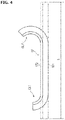
- FIG. 4 is a schematic side view for explaining the shape of the curl state of the heat-resistant insulating layer provided separator.
- FIG. 4 is thus a schematic side view from the direction in which a curl is visible in the state where curling occurs.
- the separator 17 is provided with a heat-resistant insulating layer 172 on one surface of the resin porous body 171.
- the separator 17 has, as shown in FIG. 3 , in a planar state, a length of L at one side of the separator 17, a thickness of D, respectively.
- the length L at the one side of the separator 17 is measured in the direction of curling, for example, and represents a short side of the rectangular separator 17.
- L the length of the long side direction is referred to as L.
- the separator 17 is shaped in rectangular and sized such that the length of at least one side is 100 mm or more (the thickness is defined as previously described).
- the size of the separator 17 is defined in relation to the size of the electrode. For example, when the aspect ratio of the electrode, defined as the aspect ratio of a positive electrode active material layer, may range from 1 to 3, the aspect ratio of the separator 17 is sized accordingly.
- FIG. 4 a state is shown in which curls CL1 and CL2 occur to the separator 17.
- FIG.4 in phantom line (two-dot chain line), a flat state before curling is shown (state of FIG. 3 ).
- the curls CL1 and CL2 occur at the end of the separator 17.
- the possible cause of occurrence of such curling is due to drying process. More specifically, in a nonaqueous electrolyte system, with too much moisture, the expected performance cannot be sufficiently exhibited. Thus, it is necessary to dry the separator to remove moisture. Therefore, the separators 17 in stock will be laminated after removing the moisture by drying.
- the degrees of shrinkage or contraction is different from each other. This is because the materials of the resin porous substrate 171 and the heat-resistant insulating layer 172 are different. Curl is generated due to the difference in the degree of contraction.
- the shrinkage is reduced so as to leave a water content within a predetermined range in the separator 17 in the drying step.
- the preferred range of curl amount may be defined by a length ratio Y after shrinkage representing a ratio of shrinkage of the resin porous substrate 171 and that of the heat-resistant insulating layer 172.
- FIG. 5 is a diagram illustrating a method for obtaining the arc central angle of the curl and the length ratio Y after shrinkage.
- Length ratio Y after shrinkage represents a ratio shrinkage of the resin porous substrate 171 and the heat-resistant insulating layer 172.
- the length ratio is defined as the ratio of the amount of shrinkage of the resin porous body 171 due to drying to the amount of shrinkage of the heat-resistant insulation layer. Therefore, when these shrunken or contraction values are measurable, the ratio may be defined as the ratio Y after shrinkage.
- the ratio Y after shrinkage is determined to be obtained from the central angle of the arc of the curl generated by shrinkage of the separator.
- a perpendicular line p1 is drawn for the separator plane from the origin cs part of the curl of the separator 17.
- Another perpendicular line p2 is drawn from curling endpoint ce (i.e. the end of the separator 17) with respect to the separator plane.
- the central angles ⁇ 1 and ⁇ 2 formed by and at the crossing point "o" of these perpendiculars p1 and p2 as the center of the arc are obtained.
- FIG.6 is a schematic diagram for explaining the origin cs of curl.
- the curl origin cs shows the position in which curl occurs. As shown in FIG. 6 , by drawing lines L along the curl from an extension line (plane extension) Q of the separator plane and the position is obtained in which the angle ⁇ formed by the plane extension Q and the line L starts to assume about 1° to 2°.
- the length ratio Y after shrinkage is calculated using the central angles ⁇ 1 and ⁇ 2 of the arc of the curl thus obtained according to the following equation (2).
- Y 1 ⁇ 2 ⁇ ⁇ 1 + ⁇ 2 / 360 ° X
- FIG. 7 is a graph showing the relationship between the length ratio Y after shrinkage and the ratio X representative of the thickness D to the length L of the separator 17. In FIG. 7 , the range satisfying the equation (1) is indicated.
- the water content contained in the separator 17 is maintained in a predetermined range.
- the water content to remain in the predetermined range in the drying step is controlled to satisfy the following equation (3) using the water content ratio W between water contents before and after the drying step.
- the water content that can suppress curling of the separator 17 may be indicated by the water content ratio.
- Water contained in the separator 17 varies depending upon a production process of the separator 17 and temperature and humidity of a place in which the product has been stored.
- the separator 17 will be dried so that the maximum value of the water content of the separator 17 reaches a specific range. Whether or not the separator 17 will be curled is dependent not from the absolute water content before and after drying, but rather dependent on the water content that has been decreased.
- 950 ppm is set as the upper limit of the water content of the entire heat-resistant insulated layer provided separator. This is because, if too much moisture is present in the separator 17, it is possible that the water content remains in the battery after production of the battery (after sealing). Due to reaction of water with electrolyte solution and through electrolysis, gas is generated. The gas component leads to decrease in battery performance by blocking to form electrode coating during the initial charging. If about 950 ppm is available as the maximum value of the water content of the separator 17, the situation does not lead to the performance degradation. In the present embodiment, a target value of 950 ppm is set during the drying step. That is, the separator will be dried so that the water content is equal to or less than this target value (although water content of the predetermined range should remain).
- the lower limit of the water content of the separator 17 is not particularly limited. Thus, as described above, occurrence of curl is prevented by satisfying equation (3) described above.
- the degree or extent of curl also depends on the moisture or water content decrease rate in the drying step.
- the water decrease rate is defined as ((1-W) / T), which is preferable to satisfy the following equation (5). 1 ⁇ W / T ⁇ 1.2 where, W is the water content ratio. T is the time 0.5hr.
- FIG. 8 is a schematic exploded perspective view for explaining a production method of a laminated battery. In the figure, details such as the current collector, the active material, leads, and the external package are omitted.
- a positive electrode 150 that is formed into a sheet, a separator 17, and a negative electrode 130 are laminated or stacked in this order. At this time, if curl has occurred in the separator 17, the end of the separator 17 warped by curling will be pressed down by the negative electrode 130 (or positive electrode 150) laminated thereon.
- the laminated state occurs such that the ends of the separator 17 are laminated in folded state.
- a heat-resistant insulating layer was formed. While formed in a roll form with a width of 200 mm, a separator was prepared with the heat-resistant insulating layer on one side thereof. The thickness D of the heat-resistant insulating layer provided separator was measured by a thickness measuring instrument.
- Example 1 is conditioned to the highest dew point (highest humidity), and the dew point is progressively lowered in the order of Examples 2, 3, and Comparative Example 2.
- Comparative Example 1 did not undergo a drying step. Respective dew points representing the drying condition are shown in Table 1.
- the water contents were measured once before a drying step, and at several times in 30-minute intervals after drying-start until elapse of 8 hours.
- the water decrease rate was obtained based on the water contents at each elapsed time.
- Sample collection A plurality of sheets for each of Examples and Comparative Examples of the heat-resistant insulating layer provided separator (sized 200 ⁇ 200 mm) were prepared according to the sample preparation procedure. Among Examples and Comparative Examples, a single sheet was intended for water content measurement, and the rest was used in the evaluation of laminate property and battery performance.
- a sheet of heat-resistant insulating layer provided separator for water content measurement was cut into a sample with the width of about 0.5 cm and the length of about 2.5 cm. The water content before drying was specifically measured by the following measuring method. After starting to dry, the sheet of the heat-resistant insulating layer provided separator was cut into samples (about 0.5 cm width ⁇ about 2.5 cm length). The water content was thus measured at 30 minute intervals until 8 hours after the start of drying.
- Measuring method Measurement of water content was carried out by the coulometric titration method, using the Karl Fischer method. More specifically, measurement was made by using CA-200 Karl Fischer moisture meter (manufactured by Mitsubishi Chemical Analytic Tec), a water vaporizer VA-236S (manufactured by Mitsubishi Chemical analytic Tech), and Aquamicron (TM) AX, Aquamicron (R) CXU as reagent, respectively.
- the heating temperature of the water vaporizer was set to a target temperature 120 ° C. After reaching the target temperature, the water vaporizer was purged using dry nitrogen as a carrier gas. Exact weight of the sample for water content measurement described above was measured. Subsequently, the sample is stuffed in a vial bottle and capped. Thereafter, the vial bottle was set in the water vaporizer and heated for water content measurement of the sample.
- Each heat-resistant insulating layer provided separator after drying (200 ⁇ 200 mm ⁇ thickness D) of Examples and Comparative Examples was placed with the heat-resistant layer side up. A charge eliminating brush was discharged for static elimination twice and placed for 24 hours.
- the length ratio Y was obtained of the heat-resistant insulating layer provided separator after shrinkage.
- the separator was photographed from the direction of the side surface in which the curled state is visible, and a ruler and a protractor were used to obtain the central angle ⁇ of the curl from the captured image.
- the values of the length ratio Y after shrinkage are shown in Table 2.
- FIG. 9 is a graph showing the relationship between the length ratio Y after shrinkage and the ratio X representing a ratio of the thickness to the length of the separator with data of embodiments and Comparative Examples plotted.
- Examples 1, 2, 3 and Comparative Example 1 are plotted within a good range of the length ratio Y shown by equation (1).
- Y satisfying the equation: 1 ⁇ 4 ⁇ X ⁇ Y ⁇ 1 + 4 ⁇ X
- FIG. 10 is a graph showing the water content ratio W and the drying time T in Examples and Comparative Examples.
Landscapes
- Chemical & Material Sciences (AREA)
- Chemical Kinetics & Catalysis (AREA)
- Electrochemistry (AREA)
- General Chemical & Material Sciences (AREA)
- Engineering & Computer Science (AREA)
- Manufacturing & Machinery (AREA)
- Inorganic Chemistry (AREA)
- Secondary Cells (AREA)
- Cell Separators (AREA)
- Sealing Battery Cases Or Jackets (AREA)
Abstract
Description
- The present invention relates to a method for producing a lithium ion secondary battery.
- A lithium-ion secondary battery has a structure in which a positive electrode and a negative electrode are disposed to face each other through an electrolyte layer formed by a separator holding an electrolytic solution or electrolyte gel.
- As the separator, use is often made of a resin porous membrane. However, such resin-made porous film has a possibility that thermal contraction due to increase in the battery internal temperature and a short circuit associated therewith occur.
- Thus, in order to suppress heat shrinkage of the separator, a special separator has been developed that is provided with a heat resistant and insulating layer laminated on one surface of a resin porous membrane (e.g., see Patent Document 1).
- Patent Document 1:
WO 2007/066768 pamphlet - However, when a separator as described in
Patent Document 1 is applied to a flat plate laminate nonaqueous electrolyte secondary battery, a problem arises and curling occurs in the end portion of the separator during manufacture of the battery so that the separators are laminated with the curled portion folded. - Accordingly, an object of the present invention is to provide a method for producing a lithium ion secondary battery which suppresses the occurrence of curl in the heat-resistant insulating layer provided separator.
- The present invention for achieving the above object relates to a method for producing a lithium ion secondary battery in which a positive electrode, a heat-resistant insulating layer provided separator having a heat-resistant insulating layer formed of oxide particles on one surface of the resin porous substrate, and a negative electrode are laminated on one another, and a nonaqueous electrolyte is impregnated in the heat-resistant insulating layer provided separator. According to the present invention, prior to laminating the positive electrode, the heat-resistant insulating layer provided separator, and the negative electrode, a drying step is provided for drying the heat-resistant insulating layer provided separator so that the amount of water contained or water content in the heat-resistant insulating layer provided separator remains in a predetermined range.
- According to the present invention, in the drying step of drying the heat-resistant insulating layer provided separator, the water content of the heat-insulating layer provided separator is maintained within a predetermined range. Thus, it is possible to suppress the occurrence of curling due to shrinkage of the heat-resistant insulating layer separator. Therefore, it is possible to improve the yield of the lithium ion secondary battery manufactured by laminating the positive electrode, the heat-resistant insulating layer provided separator, and the negative electrode.
-
-
FIG. 1 is a perspective view showing an appearance of a flat lithium ion secondary battery as an example of a secondary battery that may be produced in accordance with an embodiment; -
FIG. 2 is a schematic sectional view showing an internal structure of a lithium ion secondary battery; -
FIG. 3 is a schematic side view for explaining the shape of the planar state of the heat-insulating layer provided separator; -
FIG. 4 is a schematic side view for explaining the shape of the curl state of the heat-resistant insulating layer provided separator; -
FIG. 5 is a diagram illustrating a method for obtaining an arc central angle of the curl and the length ratio Y after shrinkage; -
FIG. 6 is a schematic diagram for explaining the origin cs of the curl: -
FIG.7 is a graph showing the relationship between the length ratio Y after shrinkage and the ratio X of the thickness D to the length L of the separator; -
FIG. 8 is a schematic exploded perspective view for explaining a producing method of a laminated battery; -
FIG. 9 is a graph showing the relationship between the length ratio Y after shrinkage and the ratio X representing a ratio of the thickness to the length of the separator with data of embodiments and Comparative Examples plotted; and -
FIG. 10 is a graph showing the water content ratio W and the drying time T in Examples and Comparative Examples. - Below, with reference to the accompanying drawings, a description is given of embodiments according to the present invention. The same reference numerals are given to the same elements in the description of the drawings, without redundant description. Further, dimensional ratios in the drawings are somewhat exaggerated for convenience of explanation, and thus are different from the actual ratios.
-
Figure 1 is a perspective view representing the appearance of a flat lithium ion secondary battery as an example of a secondary battery that can be produced according to the present embodiment. - As shown in
FIG. 1 , the flat lithium ionsecondary battery 10 has a rectangular flat shape. Apositive electrode tab 27 and anegative electrode tab 25 for drawing electric power are pulled out from both sides thereof, as illustrated inFIG. 1 . - A power generating
element 21 is clad or enveloped by a batteryexternal material 29 of the lithium ionsecondary battery 10 with the periphery thereof being thermally fused. - The power generating
element 21 is sealed in a state with thepositive electrode tab 27 and thenegative electrode tab 25 being pulled out to the outside. - Pulling-out position of the electrode tabs are not particularly limited in the manner shown in
FIG. 1 . The tabs of the positive electrode and negative electrode may be pulled out from the same side. Also, thepositive electrode tab 27 and thenegative electrode tab 25 may be divided into a plurality of tabs, and allocated to each side so as to be pulled out, respectively. Thus, the manner of pulling-out is not limited to that shown inFIG. 1 . - In such a lithium ion
secondary battery 10, for example, the ratio of battery area (area of the whole battery including the external material) to rated capacity is 5 cm 2/Ah or more, and the rated capacity is 3Ah more. -
FIG. 2 is a schematic cross-sectional view illustrating the internal structure of the lithium ion secondary battery. - As shown in
FIG. 2 , the laminated lithium ionsecondary battery 10 in the present embodiment comprises a structure in which a substantially rectangularpower generating element 21, in which a charge and discharge reaction progresses, is sealed inside a batteryexterior material 29 comprising an outer package. Here, the power generatingelement 21 comprises a structure in which apositive electrode 150, aseparator 17, and anegative electrode layer 130 are laminated or stacked. - Note that the
separator 17 incorporates a non-aqueous electrolyte (for example, a liquid electrolyte). Thepositive electrode 150 comprises a structure in which positive electrodeactive material layers 15 are disposed on both sides of the positive electrodecurrent collector 12. Thenegative electrode 130 comprises a structure in which negative electrodeactive material layers 13 are disposed on both sides of the negative electrodecurrent collector 11. - The
separator 17 in this embodiment is formed in such a separator provided with a heat-resistant insulating layer on one surface of the resin porous substrate (simply referred to asseparator 17 in the present embodiment). - In the laminate or stacked structure, the negative electrode 130 (negative
current collector 11 plus negative active material layer 13), the separator 17 (containing nonaqueous electrolyte solution as electrolyte) and the positive electrode 150 (positivecurrent collector 12 and positive active material layer 15) are laminated in this order. Thus, aunit cell layer 19 is constituted by thenegative electrode 130, theseparator 17, and thepositive electrode 150. - The lithium ion
secondary battery 10 illustrated inFIG. 1 shows six singleunit cell layers 19 which are laminated. Needless to say, the actual battery is not limited to such a specific number of layers. - Thus, each single cell comprises a structure in which each unit cell is configured to be connected in parallel.
- The positive electrode
current collector 12 and the negative electrodecurrent collector 11 comprise a structure in which a positive electrode collector plate (tab) 27 and a negative electrode collector plate (tab) 25 are respectively attached to each electrode (positive electrode and negative electrode), and led to the outside of the batteryexterior material 29 by being sandwiched by the ends of the batteryexterior material 29. The positiveelectrode collector plate 27 and the negativeelectrode collector plate 25 may be respectively attached to the positiveelectrode current collector 12 and the negativeelectrode current collector 11 of the associated electrode via a positive electrode lead and a negative electrode lead (not shown), if necessary, by ultrasonic welding or resistance welding. - The positive electrode
active material layer 15 comprises a positive electrode active material. Any positive electrode active material is generally acceptable as long as used in a lithium ionsecondary battery 10. For example, lithium-transition metal complex oxides including LiMn2O4, LiCoO2, LiNiO2, Li(Ni-Co-Mn)O2, and those in which a portion of these transition metals is replaced by another element may be used. Also, lithium-transition metal phosphate compounds, lithium transition metal sulfate compounds are acceptable. When necessary, two or more of the positive electrode active materials may be used. Preferably, in view of capacity and output characteristics, lithium-transition metal complex oxides are used as the positive electrode active material. Needless to say that, as a positive electrode active material, materials other than the above may be used. - In addition, the positive electrode
active material layer 15 may comprise additives such as surface active surfactants, conductive assistants, binders, electrolytes (polymer matrix, ion-conduction polymers, electrolytic solutions), and lithium salts to enhance ion conductivity, when necessary. These additives may as well used as long as available for a known lithium ionsecondary battery 10. - The negative electrode
active material 13 includes a negative electrode active material. - Such negative electrode active material is generally acceptable as long as used in a lithium ion
secondary battery 10. For example, carbon materials such as graphite (graphite), soft carbon, hard carbon, a lithium-transition metal composite oxide (e.g., Li4Ti5 O12), a metal material, and lithium alloy-based negative electrode materials may be listed. Two or more kinds of negative electrode active materials may be used in combination. Preferably, capacitance, from the viewpoint of capacity and output characteristics, a carbon material or a lithium-transition metal composite oxide is used as the negative electrode active material. Incidentally, it is needless to say that a negative electrode active material other than the above may be used as well. - The negative electrode
active material layer 13 may optionally include an additive, such as a surfactant, a conductive additive, a binder, an electrolyte (polymer matrix, ion-conducting polymer, such as an electrolytic solution), and lithium salt for improving ion conductivity. - These additives may as well be used as long as available for a conventional lithium ion
secondary battery 10 - The electrolyte layer in the present embodiment has a structure in which an electrolyte is impregnated in a
separator 17. - The
separator 17 functions to hold the electrolyte and secure lithium ion conductivity between thepositive electrode 150 and thenegative electrode 130 as well as a partition wall between thepositive electrode 150 and thenegative electrode 130. Theseparator 17 is formed as a heat-resistant insulating layer provided separator having a heat-resistant insulating layer on one surface of a resin porous substrate. Details of theseparator 17 itself will be described below. - The electrolytes to be infiltrated or impregnated in the separator are not particularly limited as long as a nonaqueous electrolyte is employed such as used in a lithium ion
secondary battery 10. - For example, a liquid electrolyte can be used. The electrolyte layer has a form in which lithium salt, which is a supporting salt, is dissolved in an organic solvent. Examples of organic solvents that are used include carbonates such as ethylene carbonates (EC), propylene carbonates (PC), dimethyl carbonate (DMC), diethyl carbonates (DEC), and ethyl methyl carbonates, etc. Two or more types may be used as a mixture. In addition, compounds that can be added to the active material layer of electrodes such as Li(CF3SO2)2N, Li(C2F5SO2)2N, LiPF6, LiBF4, LiClO4, LiAsF6, and LiTaF6, LiCF3SO3 may be employed as the lithium salt as well.
- While the materials that constitute the current collector are not particularly limited, metal is preferably used.
- Specific examples of metals include aluminum, nickel, iron, stainless steel, titanium, copper, and other alloys.
- In addition, a clad material of these metals, or a plating material may be preferably used.
- Also with respect to current collector, the material is not particularly limited as long as it is used in a lithium ion
secondary battery 10. - Moreover, the positive electrode lead and negative electrode lead are not particularly limited and also made of similar metal that is used for the collector.
- As the
battery case body 29, a laminate film comprising aluminum may be used. An example of the laminate film may be comprised of a three-layer structure formed by laminating polypropylene, aluminum, and nylon (registered trademark) in this order. It is not particularly limited as long as it is used in other lithium-ionsecondary battery 10. A known metal case may be also used. - A description is now given of the separator according to the present embodiment.
- The
separator 17 in the present embodiment is formed as a heat-resistant insulating layer provided separator. In theseparator 17, a heat-resistantinsulating layer 172 is provided on one surface of a resin porous body or substrate 171 (seeFIG. 3 ). - The resin
porous substrate 171 may be formed, for example, in a porous sheet containing an organic resin to absorb and hold an electrolyte such as a conventional woven or non-woven sheet. The resin porous substrate is not particularly limited. As an example, the porous sheet may be formed, for example, in a microporous membrane composed of microporous polymer. Such polymers may be, for example, a polyolefin monolayer film such as polyethylene (PE), polypropylene (PP), multilayer films, polyimide, and aramide and the like. Particularly, a polyolefin microporous film has a property of being chemically stable with respect to organic solvents, and thus is preferred since it is possible to suppress the reactivity with the electrolytic solution. - The thickness of the porous sheet cannot be uniquely defined since it is different according to the application areas. However, in applications of the secondary battery for driving an electric motor for a vehicle, it is desirable to use a single layer or a multilayer with a thickness range between 4 and 35 µm. The pore diameter of the porous sheet is preferably at most 1µm or less (typically, a pore size of about tens nm), and the porosity is preferably 20 to 80%.
- As the woven or nonwoven fabric, for example, polyesters such as polyethylene terephthalate (PET); polyolefin such as PP, and PE; polyimide, aramid and the like may be used. The bulk density of the woven or nonwoven fabric is not particularly limited as long as sufficient battery characteristics can be obtained by the electrolytic solution impregnated. The porosity of woven or nonwoven fabric ranges preferably between 50 and 90%. Further, the thickness of the woven or nonwoven fabric ranges preferably between 5 and 35µm. It is preferable to use 5µm or more thickness because of superior retention of the electrolyte with excessive increase in resistance avoided.
- Known oxide particles conventionally used are used for the heat-resistant
insulating layer 172, and thus are not particularly limited. For example, as the material of the oxide particles, such material with melting or thermal softening point of 150°C or higher, preferably having a high heat resistance of 240°C or higher may be used. By using the material with such a high heat resistance, it is possible to effectively prevent shrinkage due to heat on theseparator 17. - The oxide particles possess an electrically insulating property, stable to the solvent used in the preparation of the electrolyte solution and heat insulating
layer 172. Further, it is preferable for the oxide particles to be electrochemically stable in the range of the battery operation voltage so as not to be easily susceptible to redox reaction. - Such oxide particles are preferably inorganic particles in view of stability. Further, the oxide particles is preferably microparticles in view of disposability, and the secondary particle diameter may be for example in the range between 100 nm and 4 µm, preferably in the range between 300 nm and 3 µm, even more preferably between 500 nm and 3 µm.
- The shape of oxide particles is not particularly limited and may comprise a shape close to a spherical shape, a plate shape, a rod shape, or may be of a needle-like form.
- The inorganic particles (inorganic powder) with melting point or thermal softening point at 150°C or more, is not particularly limited. However, for example, inorganic oxides such as iron oxide (FeO), SiO2, Al2O3, aluminosilicates (aluminosilicate), TiO2, BaTiO2, ZrO2; inorganic nitrides such as such as aluminum nitride, silicon nitride; poorly soluble ionic crystals such as calcium fluoride, barium fluoride, barium sulfate; covalent crystal such as silicon, diamond; clays such as montmorillonite, and other particles may be listed. Inorganic oxides may be also mineral resource-derived substances or artificial materials such as boehmite, zeolite, apatite, kaoline, mullite, spinel, olivine, mica. Further, inorganic particles may be formed by covering a surface of conductive material such as metal; conductive oxide such as SnO2, tin-indium oxide (ITO); carbonaceous materials such as carbon black, graphite; with electrically insulating material such as the inorganic oxides described above so as to impart electrical insulation. Among them, since particles of the inorganic oxide can easily be applied onto the resin
porous body 171 as a water dispersed slurry, it is possible to produce aseparator 17 in a simple method, which is preferable. Among the inorganic oxides, Al2O3, SiO2, and aluminosilicates (aluminosilicate) are especially preferred. - Note that the heat-resistant particles as described above may be used one kind alone or may be used in combination of two or more.
- The thickness of the heat-
resistant insulation layer 172 is appropriately determined depending on the battery type and application so that no particular limitation is imposed. However, for example, a heat-resistant insulating layer provided separator with a heat-resistantinsulating layer 172 may have a preferable total thickness of the entire separator in the range of about 10 to 35µm. With such a thickness, the retention of the electrolyte in the resinporous body 171 portion is maintained good, and increase in resistance can be suppressed. - A description will now be given of the shape of the heat-resistant insulating layer provided separator.
FIG. 3 is a schematic side view for explaining the shape of the planar state of the heat-insulating layer provided separator.FIG. 4 is a schematic side view for explaining the shape of the curl state of the heat-resistant insulating layer provided separator. -
FIG. 4 is thus a schematic side view from the direction in which a curl is visible in the state where curling occurs. - The
separator 17 is provided with a heat-resistantinsulating layer 172 on one surface of the resinporous body 171. Theseparator 17 has, as shown inFIG. 3 , in a planar state, a length of L at one side of theseparator 17, a thickness of D, respectively. However, the length L at the one side of theseparator 17 is measured in the direction of curling, for example, and represents a short side of therectangular separator 17. Of course, due to the environment in the production step, if the long side is more easily curled, the length of the long side direction is referred to as L. - The
separator 17 is shaped in rectangular and sized such that the length of at least one side is 100 mm or more (the thickness is defined as previously described). The size of theseparator 17 is defined in relation to the size of the electrode. For example, when the aspect ratio of the electrode, defined as the aspect ratio of a positive electrode active material layer, may range from 1 to 3, the aspect ratio of theseparator 17 is sized accordingly. - Now, a description is made of a state where curling occurs in the
separator 17. - In
FIG. 4 , a state is shown in which curls CL1 and CL2 occur to theseparator 17. InFIG.4 , in phantom line (two-dot chain line), a flat state before curling is shown (state ofFIG. 3 ). As illustrated, the curls CL1 and CL2 occur at the end of theseparator 17. The possible cause of occurrence of such curling is due to drying process. More specifically, in a nonaqueous electrolyte system, with too much moisture, the expected performance cannot be sufficiently exhibited. Thus, it is necessary to dry the separator to remove moisture. Therefore, theseparators 17 in stock will be laminated after removing the moisture by drying. - During the drying step, between a porous resin body or
substrate 171 of theseparator 17 and a heat-resistantinsulating layer 172 formed on one surface thereof, the degrees of shrinkage or contraction is different from each other. This is because the materials of the resinporous substrate 171 and the heat-resistantinsulating layer 172 are different. Curl is generated due to the difference in the degree of contraction. In the present embodiment, the shrinkage is reduced so as to leave a water content within a predetermined range in theseparator 17 in the drying step. - The preferred range of curl amount may be defined by a length ratio Y after shrinkage representing a ratio of shrinkage of the resin
porous substrate 171 and that of the heat-resistantinsulating layer 172. The preferable range of the length ratio after shrinkage is configured such that theseparator 17 is shaped to satisfy the equation (1) described below. Therefore, in the drying step, the curl amount is controlled so as to be in the range defined in the equation (1).
entire separator 17 in a plane state (in which no curl occurs) to the length L in the direction of the curl occurrence, i.e., X = D / L. - Thus, by maintaining the length ratio Y after shrinkage to satisfy equation (1), fold or crease would not occur even with some curling occurring. Thus, it is possible to improve the yield of the lamination step.
- Now, a description is given of the method to obtain the length ratio Y after shrinkage.
-
FIG. 5 is a diagram illustrating a method for obtaining the arc central angle of the curl and the length ratio Y after shrinkage. - Length ratio Y after shrinkage represents a ratio shrinkage of the resin
porous substrate 171 and the heat-resistantinsulating layer 172. In other words, the length ratio is defined as the ratio of the amount of shrinkage of the resinporous body 171 due to drying to the amount of shrinkage of the heat-resistant insulation layer. Therefore, when these shrunken or contraction values are measurable, the ratio may be defined as the ratio Y after shrinkage. - However, since the resin
porous body 171 is firmly adhered to the heat-resistantinsulating layer 172, it is difficult to measure each shrinkage amount separately. Therefore, the ratio Y after shrinkage is determined to be obtained from the central angle of the arc of the curl generated by shrinkage of the separator. - In order to determine the length ratio Y after shrinkage, when viewed from the direction in which curls are visible, respective central angles θ1 and θ2 of the arc of curls CL1 and CL2, which occur at both ends, are first obtained.
- Then a perpendicular line p1 is drawn for the separator plane from the origin cs part of the curl of the
separator 17. Another perpendicular line p2 is drawn from curling endpoint ce (i.e. the end of the separator 17) with respect to the separator plane. The central angles θ1 and θ2 formed by and at the crossing point "o" of these perpendiculars p1 and p2 as the center of the arc are obtained. - A description is given of the origin cs of curl.
FIG.6 is a schematic diagram for explaining the origin cs of curl. - The curl origin cs shows the position in which curl occurs. As shown in
FIG. 6 , by drawing lines L along the curl from an extension line (plane extension) Q of the separator plane and the position is obtained in which the angle α formed by the plane extension Q and the line L starts to assume about 1° to 2°. - The length ratio Y after shrinkage is calculated using the central angles θ1 and θ2 of the arc of the curl thus obtained according to the following equation (2).

-
FIG. 7 is a graph showing the relationship between the length ratio Y after shrinkage and the ratio X representative of the thickness D to the length L of theseparator 17. InFIG. 7 , the range satisfying the equation (1) is indicated. - In the drying step, control is executed so as to be maintained within a range between a line representing Y= 1-4πX and line representing Y = 1 + 4πX (indicated as "satisfactory range" in the figure).
- In order to satisfy the length ratio Y after shrinkage as required in equation (1), the water content contained in the
separator 17 is maintained in a predetermined range. - The water content to remain in the predetermined range in the drying step is controlled to satisfy the following equation (3) using the water content ratio W between water contents before and after the drying step.


- Now, description is made of the reason why the water content that can suppress curling of the
separator 17 may be indicated by the water content ratio. Water contained in theseparator 17 varies depending upon a production process of theseparator 17 and temperature and humidity of a place in which the product has been stored. On the other hand, in the production process of the laminated battery, theseparator 17 will be dried so that the maximum value of the water content of theseparator 17 reaches a specific range. Whether or not theseparator 17 will be curled is dependent not from the absolute water content before and after drying, but rather dependent on the water content that has been decreased. Thus, it is preferable to use the water content ratio as controlling parameter as the water content that can suppress curl of theseparator 17 from occurring. - Regarding the maximum value of the water content after drying w2 (absolute value), because of the use of non-aqueous electrolyte, 950 ppm is set as the upper limit of the water content of the entire heat-resistant insulated layer provided separator. This is because, if too much moisture is present in the
separator 17, it is possible that the water content remains in the battery after production of the battery (after sealing). Due to reaction of water with electrolyte solution and through electrolysis, gas is generated. The gas component leads to decrease in battery performance by blocking to form electrode coating during the initial charging. If about 950 ppm is available as the maximum value of the water content of theseparator 17, the situation does not lead to the performance degradation. In the present embodiment, a target value of 950 ppm is set during the drying step. That is, the separator will be dried so that the water content is equal to or less than this target value (although water content of the predetermined range should remain). - Note that the lower limit of the water content of the
separator 17 is not particularly limited. Thus, as described above, occurrence of curl is prevented by satisfying equation (3) described above. - The degree or extent of curl also depends on the moisture or water content decrease rate in the drying step. In order to suppress the occurrence of curl, the water decrease rate is defined as ((1-W) / T), which is preferable to satisfy the following equation (5).

- The water decrease rate is calculated by measuring at certain time intervals the water content of the
separator 17 and using the above equations (4) and (5). Regarding the time intervals, the water content w1 is measured before starting drying, and after elapse of first 0.5 hour after starting of the drying (30 minutes) (T = 0.5 hr.), the water content w2 after drying is measured. Although the drying step is carried out to reach the target value, water falls out substantially at early time after the start of drying. Thus, the water decrease rate is to be determined by the water content of the first 30 minutes. The water decrease rate is related to the occurrence of curling in the initial drying step during which water is most prone to escape. - As described above, by satisfying the above equation (1) by the shape of the
separator 17, and by controlling the water content so as to satisfy at least one of equations (3) and (5), it is possible to suppress occurrence of curling of the heat-resistant insulating layer providedseparator 17. Thus, in the production of the laminated battery using the heat-resistant insulating layer providedseparator 17, it is possible to suppress fold due to curled end, to thereby improve the yield. - Now a description is given of a production method of a laminated or stacked battery.
-
FIG. 8 is a schematic exploded perspective view for explaining a production method of a laminated battery. In the figure, details such as the current collector, the active material, leads, and the external package are omitted. - As shown in
FIG. 8 , in the laminated battery, apositive electrode 150 that is formed into a sheet, aseparator 17, and anegative electrode 130 are laminated or stacked in this order. At this time, if curl has occurred in theseparator 17, the end of theseparator 17 warped by curling will be pressed down by the negative electrode 130 (or positive electrode 150) laminated thereon. - Subsequently, when completed as a battery stack, the laminated state occurs such that the ends of the
separator 17 are laminated in folded state. - Now a description is given of the examples in the present embodiment, and a comparative example in which the present embodiment is not applied.
- By applying a slurry using alumina as heat-resistant particles on one side of the PP substrate and subsequently drying in hot air, a heat-resistant insulating layer was formed. While formed in a roll form with a width of 200 mm, a separator was prepared with the heat-resistant insulating layer on one side thereof. The thickness D of the heat-resistant insulating layer provided separator was measured by a thickness measuring instrument.
- The conditions and experimental results of the Examples and Comparative Examples are shown in Tables 1 and 2 below.
- Each of Examples and Comparative Examples was cut into the same size (square shape with the length at one side L = 200 mm).
- A drying step was carried out for each of Examples and Comparative Examples while controlling the environmental temperature and humidity with different dew point temperatures. Example 1 is conditioned to the highest dew point (highest humidity), and the dew point is progressively lowered in the order of Examples 2, 3, and Comparative Example 2.
- Note that Comparative Example 1 did not undergo a drying step. Respective dew points representing the drying condition are shown in Table 1.
- The water contents were measured once before a drying step, and at several times in 30-minute intervals after drying-start until elapse of 8 hours. The water decrease rate was obtained based on the water contents at each elapsed time.
- Sample collection: A plurality of sheets for each of Examples and Comparative Examples of the heat-resistant insulating layer provided separator (sized 200 × 200 mm) were prepared according to the sample preparation procedure. Among Examples and Comparative Examples, a single sheet was intended for water content measurement, and the rest was used in the evaluation of laminate property and battery performance. In order to measure the water content before drying, a sheet of heat-resistant insulating layer provided separator for water content measurement was cut into a sample with the width of about 0.5 cm and the length of about 2.5 cm. The water content before drying was specifically measured by the following measuring method. After starting to dry, the sheet of the heat-resistant insulating layer provided separator was cut into samples (about 0.5 cm width × about 2.5 cm length). The water content was thus measured at 30 minute intervals until 8 hours after the start of drying.
- Measuring method: Measurement of water content was carried out by the coulometric titration method, using the Karl Fischer method. More specifically, measurement was made by using CA-200 Karl Fischer moisture meter (manufactured by Mitsubishi Chemical Analytic Tec), a water vaporizer VA-236S (manufactured by Mitsubishi Chemical analytic Tech), and Aquamicron (TM) AX, Aquamicron (R) CXU as reagent, respectively.
- First, the heating temperature of the water vaporizer was set to a target temperature 120 ° C. After reaching the target temperature, the water vaporizer was purged using dry nitrogen as a carrier gas. Exact weight of the sample for water content measurement described above was measured. Subsequently, the sample is stuffed in a vial bottle and capped. Thereafter, the vial bottle was set in the water vaporizer and heated for water content measurement of the sample.
- Each heat-resistant insulating layer provided separator after drying (200 × 200 mm × thickness D) of Examples and Comparative Examples was placed with the heat-resistant layer side up. A charge eliminating brush was discharged for static elimination twice and placed for 24 hours. The length ratio Y was obtained of the heat-resistant insulating layer provided separator after shrinkage. When calculating the length ratio Y after shrinkage, the separator was photographed from the direction of the side surface in which the curled state is visible, and a ruler and a protractor were used to obtain the central angle θ of the curl from the captured image. The values of the length ratio Y after shrinkage are shown in Table 2.
- By laminating or stacking a positive electrode with the heat-resistant layer facing the positive electrode side, a separator, and a negative electrode of each of Examples and Comparative Examples alternately in twenty layers to evaluate the occurrence of fold in the separator end. The lamination property is evaluated to be good when no fold took place, while evaluated to be poor when fold occurred. The results are shown in Table 2.
- By attaching electrodes on each of the positive electrode and the negative electrode of the 20-layer-battery, encasing by laminating sealant, and sealing with electrolyte filled, a secondary battery was produced. Using each secondary battery one cycle of charge and another cycle of discharge was carried out. Subsequently, a capacity retention was obtained while carrying out 200 cycles of charge-discharge operation at 45 ° C. Compared with the capacity retention of Comparative Example 1 of which the retention is set to 1, the battery sample with greater than 1 is evaluated as good, the sample with 1 or less is evaluated as defective or poor. Note that, due to lamination failure of Comparative Example 2, a secondary battery could not be produced. Therefore, the charge-discharge operation was not performed. The results are shown in Table 2.
[Table 1] Length L (mm) Thickness D (mm) Thickness/Length (D/L) Length ratio after shrinkage Y Drying condition (dew point (°C)) Example 1 200 0.025 0.00013 0.9996 -3 Example 2 200 0.025 0.00013 0.9992 -20 Example 3 200 0.025 0.00013 0.9984 -40 Comparative Example 1 200 0.025 0.00013 1.0000 ------ Comparative Example 2 200 0.025 0.00013 0.9977 -65 [Table 2] Water content before drying w1(ppm) Water content after drying w2(ppm) Water content ratio W (w1/w2) Water content decrease rate (1-W)/T Lamination property Battery performance Example 1 969 787 0.81 0.38 good good Example 2 969 562 0.58 0.84 good good Example 3 969 456 0.47 1.06 good good Comparative Example 1 969 ------ 1.00 ------ good defective Comparative Example 2 969 312 0.32 1.36 defective N/A -
FIG. 9 is a graph showing the relationship between the length ratio Y after shrinkage and the ratio X representing a ratio of the thickness to the length of the separator with data of embodiments and Comparative Examples plotted. - As shown, Examples 1, 2, 3 and Comparative Example 1 are plotted within a good range of the length ratio Y shown by equation (1). In other words, Y satisfying the equation:

- By referring to the graph along with the results of lamination property and battery performance in Table 2, when the length ratio Y after shrinkage is within a satisfactory range required by equation (1), it can be seen that both the lamination property and the battery cell performance are good.
-
FIG. 10 is a graph showing the water content ratio W and the drying time T in Examples and Comparative Examples. - As shown, with respect to Examples 1, 2 and 3, in Comparative Example 2, the water content ratio W rapidly decreased when compared within the same time period. This indicates that the water decrease rate of Comparative Example 2 is faster than Examples 1, 2 and 3. Examples 1, 2 and 3 respectively satisfy the equation: (1-W) / T ≦ 1.2. On the other hand, in Comparative Example 2, the value of (1-W) / T exceeds 1.2. Note that, in Comparative Example 1, since the drying step was not performed, in the graph, the water content ratio W is depicted as 1.0 despite elapse of time.
- From the above results, it was found that the water content ratio W is preferable when satisfying the equation; 0.4 ≦ W <1, more preferably to satisfy; 0.47 ≦ W ≦ 0.81. Further, the water decrease rate is found to be good when satisfying the equation; (1-W) / T ≦ 1.2 (with T = 0.5 hr), and found more preferable when satisfying the equation; (1-W) /T ≦ 1.06 (with T = 0.5 hr).
- Thus, as seen from the results of the lamination property and battery cell performance shown in the graph of
FIG. 10 and Table 2, it is found that Examples 1, 2, and 3 in which the water content ratio W is within the range defined by equation (3) are good in both lamination or stacking properties and battery cell performance. Also, it is better to have a slower water content decrease rate. By satisfying equation (5), a good lamination property and battery performance may be obtained. - The embodiments and examples described above have the following effects.
- (1) In the embodiments and examples, when drying the heat-resistant insulating layer provided separator, the water content is set in a predetermined range instead of completely drying the heat-resistant insulating layer provided separator. Thus, it is possible to suppress the occurrence of curling due to shrinkage of the heat-resistant insulating layer provided separator. Therefore the positive electrode, it is possible to improve the yield of the lithium ion secondary battery produced by laminating a positive electrode, the heat-resistant insulating layer provided separator, and a negative electrode.
- (2) In the embodiments and examples, after a drying step, while defining Y as a length ratio of the resin porous substrate to the heat-resistant insulating layer after shrinkage, the equation (1) described above is configured to be satisfied. Thus, even curling occurs, by satisfying the equation (1) as the shape of the separator expressed in the length ratio after shrinkage, it is possible to prevent folding or crease in the end of the separator from occurring.
- (3) In the embodiments and examples, while defining (1-W)/T as a water decrease rate during the drying step, the water decrease rate is configured to satisfy the equation (5). Thus, it is possible to prevent curling from occurring and allow the length ratio Y after shrinkage to satisfy equation (1).
- (4) In the embodiments and examples, in the drying step, as the predetermined range of the water content to be maintained when drying the heat-resistant insulating layer provided separator, a water content ratio W = w1/w2 is configured to satisfy equation (3) described above, where w1 denotes a water content before drying and w2 denotes a water content after drying. Thus, it is possible to prevent curling from occurring and allow the length ratio Y after shrinkage to satisfy equation (1).
- (5) The embodiments and examples are suited for a secondary battery with a ratio of battery cell area to rated capacity being 5 cm2 /Ah or more, and the rated capacity less than 3Ah.
- As described above, a description has been given of the embodiments and examples to which the present invention is applied. However, the present invention is not limited to the embodiments and examples. Rather, various modifications are available, and the scope of the present invention is defined by the matter described in the appended claims.
-
- 10
- lithium ion secondary battery,
- 11
- negative electrode current collector,
- 12
- positive electrode current collector,
- 13
- negative electrode active material layer,
- 15
- positive electrode active material layer,
- 17
- separator,
- 19
- unit cell layer,
- 21
- power generating element,
- 130
- negative electrode,
- 150
- positive electrode,
- 171
- resin porous substrate,
- 172
- heat-resistant insulating layer.
Claims (5)
- A method for producing a lithium ion secondary battery in which a positive electrode, a heat-resistant insulating layer provided separator having a heat-resistant insulating layer formed of oxide particles on one surface of a resin porous substrate, and a negative electrode are laminated on one another, and a nonaqueous electrolyte is impregnated in the heat-resistant insulating layer provided separator, comprising:drying the heat-resistant insulating layer provided separator before laminating so that the water content in the heat-resistant insulating layer provided separator remains in a predetermined range.
- The method for producing a lithium ion secondary battery according to claim 1, wherein, in the drying step, the heat-resistant insulating layer provided separator is dried such that the shape of the heat-resistant insulating separator after the drying step satisfies a shape expressed by a length ratio Y defined by a length ratio between the length of the resin porous substrate and the length of the heat-resistant insulating layer to satisfy the equation:

- The method for producing a lithium ion secondary battery according to one of claims 1 and 2, wherein, in the drying step, the water content is configured to decrease such that a water decrease rate ((1-w)/T) defined by a water content before drying w1, a water content after drying w2, and a drying time T satisfies the equation:

- The method for producing a lithium ion secondary battery according to any one of claims 1 to 3, wherein, in the drying step, the heat-resistant insulating layer provided separator is dried such that the water content to remain in the predetermined range is controlled to satisfy the equation:

- The method for producing a lithium ion secondary battery according to any one of claims 1 to 4, wherein the lithium ion secondary battery comprises a ratio of the battery cell area to rated capacity at 5 cm2 / Ah or more, and the rated capacity is at least 3Ah or more.
Applications Claiming Priority (1)
| Application Number | Priority Date | Filing Date | Title |
|---|---|---|---|
| PCT/JP2015/058363 WO2016147409A1 (en) | 2015-03-19 | 2015-03-19 | Method for producing lithium ion secondary battery |
Publications (3)
| Publication Number | Publication Date |
|---|---|
| EP3273504A4 EP3273504A4 (en) | 2018-01-24 |
| EP3273504A1 true EP3273504A1 (en) | 2018-01-24 |
| EP3273504B1 EP3273504B1 (en) | 2019-01-30 |
Family
ID=56918524
Family Applications (1)
| Application Number | Title | Priority Date | Filing Date |
|---|---|---|---|
| EP15885505.6A Active EP3273504B1 (en) | 2015-03-19 | 2015-03-19 | Method for producing lithium ion secondary battery |
Country Status (5)
| Country | Link |
|---|---|
| US (1) | US10770746B2 (en) |
| EP (1) | EP3273504B1 (en) |
| JP (1) | JP6390784B2 (en) |
| CN (1) | CN107112479B (en) |
| WO (1) | WO2016147409A1 (en) |
Families Citing this family (2)
| Publication number | Priority date | Publication date | Assignee | Title |
|---|---|---|---|---|
| CN108336277A (en) * | 2017-12-29 | 2018-07-27 | 深圳中兴创新材料技术有限公司 | A kind of diaphragm and preparation method thereof with ceramic coating |
| US10418550B2 (en) * | 2018-05-29 | 2019-09-17 | Nanjing University | High temperature resistant memristor based on two-dimensional covalent crystal and preparation method thereof |
Family Cites Families (10)
| Publication number | Priority date | Publication date | Assignee | Title |
|---|---|---|---|---|
| CN101218695B (en) * | 2005-12-08 | 2011-07-20 | 日立麦克赛尔株式会社 | Electrochemical element partition plate and its manufacture method and electrochemical element and its production method |
| US9166250B2 (en) * | 2006-09-07 | 2015-10-20 | Hitachi Maxell, Ltd. | Separator for battery, method for manufacturing the same, and lithium secondary battery |
| CN101209609B (en) * | 2006-12-30 | 2011-06-15 | 比亚迪股份有限公司 | Polyolefin composite thin film and preparation and application thereof |
| JP5356878B2 (en) * | 2009-03-27 | 2013-12-04 | 帝人株式会社 | Non-aqueous secondary battery separator |
| JP5609748B2 (en) * | 2011-04-11 | 2014-10-22 | トヨタ自動車株式会社 | Battery manufacturing method |
| JP5741936B2 (en) * | 2011-06-07 | 2015-07-01 | トヨタ自動車株式会社 | Lithium ion secondary battery |
| KR101777625B1 (en) * | 2011-07-06 | 2017-09-13 | 제온 코포레이션 | Porous membrane for secondary battery, separator for secondary battery, and secondary battery |
| JP5987494B2 (en) * | 2012-06-22 | 2016-09-07 | 株式会社Gsユアサ | Electricity storage element |
| WO2014002701A1 (en) * | 2012-06-29 | 2014-01-03 | 三菱樹脂株式会社 | Laminated porous film, separator for non-aqueous electrolyte secondary battery, and non-aqueous electrolyte secondary battery |
| JP6094805B2 (en) * | 2013-04-10 | 2017-03-15 | トヨタ自動車株式会社 | Secondary battery |
-
2015
- 2015-03-19 EP EP15885505.6A patent/EP3273504B1/en active Active
- 2015-03-19 JP JP2017505999A patent/JP6390784B2/en active Active
- 2015-03-19 CN CN201580070112.7A patent/CN107112479B/en active Active
- 2015-03-19 WO PCT/JP2015/058363 patent/WO2016147409A1/en active Application Filing
- 2015-03-19 US US15/544,623 patent/US10770746B2/en active Active
Also Published As
| Publication number | Publication date |
|---|---|
| JP6390784B2 (en) | 2018-09-26 |
| WO2016147409A1 (en) | 2016-09-22 |
| EP3273504B1 (en) | 2019-01-30 |
| JPWO2016147409A1 (en) | 2017-10-19 |
| US10770746B2 (en) | 2020-09-08 |
| US20180040911A1 (en) | 2018-02-08 |
| EP3273504A4 (en) | 2018-01-24 |
| CN107112479B (en) | 2019-06-07 |
| CN107112479A (en) | 2017-08-29 |
Similar Documents
| Publication | Publication Date | Title |
|---|---|---|
| EP3070767B1 (en) | Electrode, nonaqueous electrolyte battery, and battery pack | |
| JP5937776B2 (en) | Battery separator and battery | |
| JP5101569B2 (en) | Battery separator, manufacturing method thereof, and lithium secondary battery | |
| EP2169756B1 (en) | Lithium secondary battery | |
| EP2365571B1 (en) | Nonaqueous electrolyte secondary battery | |
| EP2950369B1 (en) | Energy storage device | |
| CA2586062A1 (en) | Separator for electrochemical device, and electrochemical device | |
| JP2008041581A (en) | Rolled electrode group, rectangular secondary battery, and laminated type secondary battery | |
| WO2015068680A1 (en) | Non-aqueous electrolyte secondary cell, and electric storage circuit using same | |
| JP2009181756A (en) | Lithium-ion secondary battery and electronic apparatus using the same | |
| US20220302436A1 (en) | Electrode, energy storage device, and method for manufacturing electrode | |
| EP3273504B1 (en) | Method for producing lithium ion secondary battery | |
| EP2879225B1 (en) | Electric storage device and electric storage apparatus | |
| KR101709391B1 (en) | Nonaqueous electrolyte secondary battery | |
| JPH1131508A (en) | Nonaqueous electrolyte secondary battery | |
| EP3561935B1 (en) | Nonaqueous electrolyte battery and battery pack | |
| WO2014175212A1 (en) | Electricity storage device | |
| WO2020218020A1 (en) | Negative-electrode active material, negative electrode, and secondary battery | |
| JP4109168B2 (en) | Lithium ion secondary battery | |
| JP7303084B2 (en) | lithium ion battery | |
| CN110915039A (en) | Positive electrode active material, positive electrode, battery pack, electronic device, electric vehicle, power storage device, and power system | |
| EP4030498B1 (en) | Graphite-based negative electrode active material | |
| WO2014175213A1 (en) | Electricity storage device | |
| JP4017079B2 (en) | Lithium secondary battery and manufacturing method thereof | |
| JP3887612B2 (en) | Non-aqueous electrolyte solution and lithium ion secondary battery |
Legal Events
| Date | Code | Title | Description |
|---|---|---|---|
| STAA | Information on the status of an ep patent application or granted ep patent |
Free format text: STATUS: THE INTERNATIONAL PUBLICATION HAS BEEN MADE |
|
| PUAI | Public reference made under article 153(3) epc to a published international application that has entered the european phase |
Free format text: ORIGINAL CODE: 0009012 |
|
| STAA | Information on the status of an ep patent application or granted ep patent |
Free format text: STATUS: REQUEST FOR EXAMINATION WAS MADE |
|
| 17P | Request for examination filed |
Effective date: 20170724 |
|
| A4 | Supplementary search report drawn up and despatched |
Effective date: 20171120 |
|
| AK | Designated contracting states |
Kind code of ref document: A1 Designated state(s): AL AT BE BG CH CY CZ DE DK EE ES FI FR GB GR HR HU IE IS IT LI LT LU LV MC MK MT NL NO PL PT RO RS SE SI SK SM TR |
|
| AX | Request for extension of the european patent |
Extension state: BA ME |
|
| DAV | Request for validation of the european patent (deleted) | ||
| DAX | Request for extension of the european patent (deleted) | ||
| GRAP | Despatch of communication of intention to grant a patent |
Free format text: ORIGINAL CODE: EPIDOSNIGR1 |
|
| STAA | Information on the status of an ep patent application or granted ep patent |
Free format text: STATUS: GRANT OF PATENT IS INTENDED |
|
| INTG | Intention to grant announced |
Effective date: 20181019 |
|
| GRAS | Grant fee paid |
Free format text: ORIGINAL CODE: EPIDOSNIGR3 |
|
| GRAA | (expected) grant |
Free format text: ORIGINAL CODE: 0009210 |
|
| STAA | Information on the status of an ep patent application or granted ep patent |
Free format text: STATUS: THE PATENT HAS BEEN GRANTED |
|
| AK | Designated contracting states |
Kind code of ref document: B1 Designated state(s): AL AT BE BG CH CY CZ DE DK EE ES FI FR GB GR HR HU IE IS IT LI LT LU LV MC MK MT NL NO PL PT RO RS SE SI SK SM TR |
|
| REG | Reference to a national code |
Ref country code: GB Ref legal event code: FG4D |
|
| REG | Reference to a national code |
Ref country code: CH Ref legal event code: EP |
|
| REG | Reference to a national code |
Ref country code: AT Ref legal event code: REF Ref document number: 1093965 Country of ref document: AT Kind code of ref document: T Effective date: 20190215 |
|
| REG | Reference to a national code |
Ref country code: IE Ref legal event code: FG4D |
|
| REG | Reference to a national code |
Ref country code: DE Ref legal event code: R096 Ref document number: 602015024237 Country of ref document: DE |
|
| REG | Reference to a national code |
Ref country code: LT Ref legal event code: MG4D |
|
| REG | Reference to a national code |
Ref country code: NL Ref legal event code: MP Effective date: 20190130 |
|
| PG25 | Lapsed in a contracting state [announced via postgrant information from national office to epo] |
Ref country code: NO Free format text: LAPSE BECAUSE OF FAILURE TO SUBMIT A TRANSLATION OF THE DESCRIPTION OR TO PAY THE FEE WITHIN THE PRESCRIBED TIME-LIMIT Effective date: 20190430 Ref country code: FI Free format text: LAPSE BECAUSE OF FAILURE TO SUBMIT A TRANSLATION OF THE DESCRIPTION OR TO PAY THE FEE WITHIN THE PRESCRIBED TIME-LIMIT Effective date: 20190130 Ref country code: SE Free format text: LAPSE BECAUSE OF FAILURE TO SUBMIT A TRANSLATION OF THE DESCRIPTION OR TO PAY THE FEE WITHIN THE PRESCRIBED TIME-LIMIT Effective date: 20190130 Ref country code: NL Free format text: LAPSE BECAUSE OF FAILURE TO SUBMIT A TRANSLATION OF THE DESCRIPTION OR TO PAY THE FEE WITHIN THE PRESCRIBED TIME-LIMIT Effective date: 20190130 Ref country code: PT Free format text: LAPSE BECAUSE OF FAILURE TO SUBMIT A TRANSLATION OF THE DESCRIPTION OR TO PAY THE FEE WITHIN THE PRESCRIBED TIME-LIMIT Effective date: 20190530 Ref country code: PL Free format text: LAPSE BECAUSE OF FAILURE TO SUBMIT A TRANSLATION OF THE DESCRIPTION OR TO PAY THE FEE WITHIN THE PRESCRIBED TIME-LIMIT Effective date: 20190130 Ref country code: LT Free format text: LAPSE BECAUSE OF FAILURE TO SUBMIT A TRANSLATION OF THE DESCRIPTION OR TO PAY THE FEE WITHIN THE PRESCRIBED TIME-LIMIT Effective date: 20190130 Ref country code: ES Free format text: LAPSE BECAUSE OF FAILURE TO SUBMIT A TRANSLATION OF THE DESCRIPTION OR TO PAY THE FEE WITHIN THE PRESCRIBED TIME-LIMIT Effective date: 20190130 |
|
| REG | Reference to a national code |
Ref country code: AT Ref legal event code: MK05 Ref document number: 1093965 Country of ref document: AT Kind code of ref document: T Effective date: 20190130 |
|
| PG25 | Lapsed in a contracting state [announced via postgrant information from national office to epo] |
Ref country code: RS Free format text: LAPSE BECAUSE OF FAILURE TO SUBMIT A TRANSLATION OF THE DESCRIPTION OR TO PAY THE FEE WITHIN THE PRESCRIBED TIME-LIMIT Effective date: 20190130 Ref country code: HR Free format text: LAPSE BECAUSE OF FAILURE TO SUBMIT A TRANSLATION OF THE DESCRIPTION OR TO PAY THE FEE WITHIN THE PRESCRIBED TIME-LIMIT Effective date: 20190130 Ref country code: LV Free format text: LAPSE BECAUSE OF FAILURE TO SUBMIT A TRANSLATION OF THE DESCRIPTION OR TO PAY THE FEE WITHIN THE PRESCRIBED TIME-LIMIT Effective date: 20190130 Ref country code: GR Free format text: LAPSE BECAUSE OF FAILURE TO SUBMIT A TRANSLATION OF THE DESCRIPTION OR TO PAY THE FEE WITHIN THE PRESCRIBED TIME-LIMIT Effective date: 20190501 Ref country code: IS Free format text: LAPSE BECAUSE OF FAILURE TO SUBMIT A TRANSLATION OF THE DESCRIPTION OR TO PAY THE FEE WITHIN THE PRESCRIBED TIME-LIMIT Effective date: 20190530 Ref country code: BG Free format text: LAPSE BECAUSE OF FAILURE TO SUBMIT A TRANSLATION OF THE DESCRIPTION OR TO PAY THE FEE WITHIN THE PRESCRIBED TIME-LIMIT Effective date: 20190430 |
|
| REG | Reference to a national code |
Ref country code: DE Ref legal event code: R082 Ref document number: 602015024237 Country of ref document: DE Representative=s name: PATENT- UND RECHTSANWAELTE DIEHL & PARTNER GBR, DE Ref country code: DE Ref legal event code: R081 Ref document number: 602015024237 Country of ref document: DE Owner name: ENVISION AESC JAPAN LTD., ZAMA-SHI, JP Free format text: FORMER OWNER: NISSAN MOTOR CO., LTD., YOKOHAMA-SHI, KANAGAWA, JP Ref country code: DE Ref legal event code: R082 Ref document number: 602015024237 Country of ref document: DE Representative=s name: DIEHL & PARTNER PATENT- UND RECHTSANWALTSKANZL, DE |
|
| REG | Reference to a national code |
Ref country code: GB Ref legal event code: 732E Free format text: REGISTERED BETWEEN 20190919 AND 20190925 |
|
| PG25 | Lapsed in a contracting state [announced via postgrant information from national office to epo] |
Ref country code: EE Free format text: LAPSE BECAUSE OF FAILURE TO SUBMIT A TRANSLATION OF THE DESCRIPTION OR TO PAY THE FEE WITHIN THE PRESCRIBED TIME-LIMIT Effective date: 20190130 Ref country code: DK Free format text: LAPSE BECAUSE OF FAILURE TO SUBMIT A TRANSLATION OF THE DESCRIPTION OR TO PAY THE FEE WITHIN THE PRESCRIBED TIME-LIMIT Effective date: 20190130 Ref country code: RO Free format text: LAPSE BECAUSE OF FAILURE TO SUBMIT A TRANSLATION OF THE DESCRIPTION OR TO PAY THE FEE WITHIN THE PRESCRIBED TIME-LIMIT Effective date: 20190130 Ref country code: IT Free format text: LAPSE BECAUSE OF FAILURE TO SUBMIT A TRANSLATION OF THE DESCRIPTION OR TO PAY THE FEE WITHIN THE PRESCRIBED TIME-LIMIT Effective date: 20190130 Ref country code: CZ Free format text: LAPSE BECAUSE OF FAILURE TO SUBMIT A TRANSLATION OF THE DESCRIPTION OR TO PAY THE FEE WITHIN THE PRESCRIBED TIME-LIMIT Effective date: 20190130 Ref country code: SK Free format text: LAPSE BECAUSE OF FAILURE TO SUBMIT A TRANSLATION OF THE DESCRIPTION OR TO PAY THE FEE WITHIN THE PRESCRIBED TIME-LIMIT Effective date: 20190130 Ref country code: AL Free format text: LAPSE BECAUSE OF FAILURE TO SUBMIT A TRANSLATION OF THE DESCRIPTION OR TO PAY THE FEE WITHIN THE PRESCRIBED TIME-LIMIT Effective date: 20190130 Ref country code: MC Free format text: LAPSE BECAUSE OF FAILURE TO SUBMIT A TRANSLATION OF THE DESCRIPTION OR TO PAY THE FEE WITHIN THE PRESCRIBED TIME-LIMIT Effective date: 20190130 |
|
| REG | Reference to a national code |
Ref country code: CH Ref legal event code: PL Ref country code: DE Ref legal event code: R097 Ref document number: 602015024237 Country of ref document: DE |
|
| PG25 | Lapsed in a contracting state [announced via postgrant information from national office to epo] |
Ref country code: LU Free format text: LAPSE BECAUSE OF NON-PAYMENT OF DUE FEES Effective date: 20190319 Ref country code: SM Free format text: LAPSE BECAUSE OF FAILURE TO SUBMIT A TRANSLATION OF THE DESCRIPTION OR TO PAY THE FEE WITHIN THE PRESCRIBED TIME-LIMIT Effective date: 20190130 |
|
| REG | Reference to a national code |
Ref country code: BE Ref legal event code: MM Effective date: 20190331 |
|
| PLBE | No opposition filed within time limit |
Free format text: ORIGINAL CODE: 0009261 |
|
| STAA | Information on the status of an ep patent application or granted ep patent |
Free format text: STATUS: NO OPPOSITION FILED WITHIN TIME LIMIT |
|
| PG25 | Lapsed in a contracting state [announced via postgrant information from national office to epo] |
Ref country code: AT Free format text: LAPSE BECAUSE OF FAILURE TO SUBMIT A TRANSLATION OF THE DESCRIPTION OR TO PAY THE FEE WITHIN THE PRESCRIBED TIME-LIMIT Effective date: 20190130 |
|
| 26N | No opposition filed |
Effective date: 20191031 |
|
| PG25 | Lapsed in a contracting state [announced via postgrant information from national office to epo] |
Ref country code: LI Free format text: LAPSE BECAUSE OF NON-PAYMENT OF DUE FEES Effective date: 20190331 Ref country code: CH Free format text: LAPSE BECAUSE OF NON-PAYMENT OF DUE FEES Effective date: 20190331 Ref country code: IE Free format text: LAPSE BECAUSE OF NON-PAYMENT OF DUE FEES Effective date: 20190319 |
|
| PG25 | Lapsed in a contracting state [announced via postgrant information from national office to epo] |
Ref country code: BE Free format text: LAPSE BECAUSE OF NON-PAYMENT OF DUE FEES Effective date: 20190331 Ref country code: SI Free format text: LAPSE BECAUSE OF FAILURE TO SUBMIT A TRANSLATION OF THE DESCRIPTION OR TO PAY THE FEE WITHIN THE PRESCRIBED TIME-LIMIT Effective date: 20190130 |
|
| PG25 | Lapsed in a contracting state [announced via postgrant information from national office to epo] |
Ref country code: TR Free format text: LAPSE BECAUSE OF FAILURE TO SUBMIT A TRANSLATION OF THE DESCRIPTION OR TO PAY THE FEE WITHIN THE PRESCRIBED TIME-LIMIT Effective date: 20190130 |
|
| PG25 | Lapsed in a contracting state [announced via postgrant information from national office to epo] |
Ref country code: MT Free format text: LAPSE BECAUSE OF NON-PAYMENT OF DUE FEES Effective date: 20190319 |
|
| REG | Reference to a national code |
Ref country code: DE Ref legal event code: R079 Ref document number: 602015024237 Country of ref document: DE Free format text: PREVIOUS MAIN CLASS: H01M0002160000 Ipc: H01M0050409000 |
|
| PG25 | Lapsed in a contracting state [announced via postgrant information from national office to epo] |
Ref country code: CY Free format text: LAPSE BECAUSE OF FAILURE TO SUBMIT A TRANSLATION OF THE DESCRIPTION OR TO PAY THE FEE WITHIN THE PRESCRIBED TIME-LIMIT Effective date: 20190130 |
|
| PG25 | Lapsed in a contracting state [announced via postgrant information from national office to epo] |
Ref country code: HU Free format text: LAPSE BECAUSE OF FAILURE TO SUBMIT A TRANSLATION OF THE DESCRIPTION OR TO PAY THE FEE WITHIN THE PRESCRIBED TIME-LIMIT; INVALID AB INITIO Effective date: 20150319 |
|
| PG25 | Lapsed in a contracting state [announced via postgrant information from national office to epo] |
Ref country code: MK Free format text: LAPSE BECAUSE OF FAILURE TO SUBMIT A TRANSLATION OF THE DESCRIPTION OR TO PAY THE FEE WITHIN THE PRESCRIBED TIME-LIMIT Effective date: 20190130 |
|
| P01 | Opt-out of the competence of the unified patent court (upc) registered |
Effective date: 20230330 |
|
| PGFP | Annual fee paid to national office [announced via postgrant information from national office to epo] |
Ref country code: DE Payment date: 20240124 Year of fee payment: 10 Ref country code: GB Payment date: 20240125 Year of fee payment: 10 |
|
| PGFP | Annual fee paid to national office [announced via postgrant information from national office to epo] |
Ref country code: FR Payment date: 20240123 Year of fee payment: 10 |