EP3273286A1 - Head-up display - Google Patents
Head-up display Download PDFInfo
- Publication number
- EP3273286A1 EP3273286A1 EP17182374.3A EP17182374A EP3273286A1 EP 3273286 A1 EP3273286 A1 EP 3273286A1 EP 17182374 A EP17182374 A EP 17182374A EP 3273286 A1 EP3273286 A1 EP 3273286A1
- Authority
- EP
- European Patent Office
- Prior art keywords
- image generation
- display
- wavelength
- head
- images
- Prior art date
- Legal status (The legal status is an assumption and is not a legal conclusion. Google has not performed a legal analysis and makes no representation as to the accuracy of the status listed.)
- Granted
Links
- 230000003287 optical effect Effects 0.000 claims abstract description 30
- 230000004438 eyesight Effects 0.000 claims abstract description 9
- 230000005540 biological transmission Effects 0.000 claims description 4
- 241001080024 Telles Species 0.000 description 2
- 239000004973 liquid crystal related substance Substances 0.000 description 2
- 239000010409 thin film Substances 0.000 description 2
- 230000004308 accommodation Effects 0.000 description 1
- 239000003086 colorant Substances 0.000 description 1
- 230000007547 defect Effects 0.000 description 1
- 210000000887 face Anatomy 0.000 description 1
- JEIPFZHSYJVQDO-UHFFFAOYSA-N iron(III) oxide Inorganic materials O=[Fe]O[Fe]=O JEIPFZHSYJVQDO-UHFFFAOYSA-N 0.000 description 1
- 230000007257 malfunction Effects 0.000 description 1
Images
Classifications
-
- G—PHYSICS
- G02—OPTICS
- G02B—OPTICAL ELEMENTS, SYSTEMS OR APPARATUS
- G02B27/00—Optical systems or apparatus not provided for by any of the groups G02B1/00 - G02B26/00, G02B30/00
- G02B27/01—Head-up displays
- G02B27/0101—Head-up displays characterised by optical features
-
- G—PHYSICS
- G02—OPTICS
- G02B—OPTICAL ELEMENTS, SYSTEMS OR APPARATUS
- G02B27/00—Optical systems or apparatus not provided for by any of the groups G02B1/00 - G02B26/00, G02B30/00
- G02B27/10—Beam splitting or combining systems
- G02B27/1066—Beam splitting or combining systems for enhancing image performance, like resolution, pixel numbers, dual magnifications or dynamic range, by tiling, slicing or overlapping fields of view
-
- G—PHYSICS
- G02—OPTICS
- G02B—OPTICAL ELEMENTS, SYSTEMS OR APPARATUS
- G02B27/00—Optical systems or apparatus not provided for by any of the groups G02B1/00 - G02B26/00, G02B30/00
- G02B27/10—Beam splitting or combining systems
- G02B27/14—Beam splitting or combining systems operating by reflection only
- G02B27/141—Beam splitting or combining systems operating by reflection only using dichroic mirrors
-
- G—PHYSICS
- G02—OPTICS
- G02B—OPTICAL ELEMENTS, SYSTEMS OR APPARATUS
- G02B27/00—Optical systems or apparatus not provided for by any of the groups G02B1/00 - G02B26/00, G02B30/00
- G02B27/01—Head-up displays
- G02B27/0101—Head-up displays characterised by optical features
- G02B2027/0112—Head-up displays characterised by optical features comprising device for genereting colour display
- G02B2027/0114—Head-up displays characterised by optical features comprising device for genereting colour display comprising dichroic elements
-
- G—PHYSICS
- G02—OPTICS
- G02B—OPTICAL ELEMENTS, SYSTEMS OR APPARATUS
- G02B27/00—Optical systems or apparatus not provided for by any of the groups G02B1/00 - G02B26/00, G02B30/00
- G02B27/01—Head-up displays
- G02B27/0101—Head-up displays characterised by optical features
- G02B2027/0118—Head-up displays characterised by optical features comprising devices for improving the contrast of the display / brillance control visibility
-
- G—PHYSICS
- G02—OPTICS
- G02B—OPTICAL ELEMENTS, SYSTEMS OR APPARATUS
- G02B26/00—Optical devices or arrangements for the control of light using movable or deformable optical elements
- G02B26/08—Optical devices or arrangements for the control of light using movable or deformable optical elements for controlling the direction of light
- G02B26/10—Scanning systems
- G02B26/101—Scanning systems with both horizontal and vertical deflecting means, e.g. raster or XY scanners
Definitions
- the present invention generally relates to devices for assisting the driving of motor vehicles.
- a head-up display adapted to project information (speed of the vehicle, direction to follow, malfunction of the engine, presence of obstacles, ...) at the height of the driver's gaze.
- the first type of displays uses an image forming device comprising a diffuser and a scanning unit designed to generate a light beam scanning an entrance face of the diffuser.
- the light beam at the output of the diffuser thus forms an image, which can then be projected into the field of vision of the driver of the vehicle.
- the displays of the second type use a screen that generates an image, which is then projected into the driver's field of vision.
- the present invention proposes a head-up display as defined in the introduction, in which the mirror is a spectrally selective optical filter adapted to predominantly reflect the light in at least a first wavelength, and mainly transmit the light in at least a second wavelength distinct from said first wavelength.
- the spectrally selective optical filter makes it possible to reflect to the combiner the light emitted by the first image generation unit in said first wavelength, and to transmit to the combiner the light emitted by the second image generation unit in said second wavelength.
- the spectrally selective optical filter makes it possible to filter the images generated by the two image generation units, so that these images have no overlapping defects and reduce the readability of the information projected in the field. of vision of the driver.
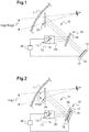
- FIG. 1 there is shown a head-up display 10 equipping a motor vehicle.
- This head-up display 10 comprises two image generation units 11, 12 driven by a computer 30, and an optical projection assembly 18.
- the optical projection assembly 18 is designed to project the images emitted by the two image generation units 11, 12 into the driver's field of view.
- this mirror is a spectrally selective optical filter 19, adapted to predominantly reflect the light in at least a first wavelength ⁇ 1 , and mainly to transmit the light in at least a second length wavelength ⁇ 4 distinct from said first wavelength ⁇ 1 .
- this spectrally selective optical filter 19 will be designed here to reflect light in a finite number of wavelengths ⁇ 1 , ⁇ 2 , ⁇ 3 , and to transmit light in several wavelength bands ⁇ which do not do not include these wavelengths ⁇ 1 , ⁇ 2 , ⁇ 3 ( ⁇ 4 being then any wavelength belonging to one of these bands of wavelengths ⁇ ).
- FIG. figure 1 the embodiment of the head-up display 1 shown in FIG. figure 1 .
- the first image generation unit 11 is of the "emissive" type. It comprises a diffuser 15 and a scanning unit which generates a light beam of variable direction so as to be able to scan the rear face of the diffuser 15.
- the scanning unit more specifically comprises a beam forming module 13 and one or more mirror (s) mobile (s) 14, for example realized in the form of an electromechanical microsystem (or MEMS for "MicroElectroMechanical System ").
- the beam forming module 13 could comprise a single source of monochromatic light.
- the respective light beams of these three laser diodes are combined (for example using partially reflecting mirrors) to form a single polychromatic light beam (here laser) emitted at the output of the beam forming module 13.
- light beam generated by the beam forming module 13 is directed towards the (or) mobile mirror 14, whose orientation is controlled by a control module so that the reflected light beam scans the rear face of the diffuser 15 .
- the second image generation unit 12 is of the "light modulation” type. It comprises a screen 17, here an LCD (or LCD for “Liquid Crystal Display ”) thin film transistors (or TFT for "Thin-Film Transistor” ). It also comprises here a backlighting device 16 located at the rear of the screen 17. This backlighting device 16 comprises a plurality of light-emitting diodes distributed behind the liquid crystals of the screen 17.
- the second image generation unit 12 is adapted to emit light in a large band of wavelengths, for example between 400 and 800 nm.
- this band of wavelengths comprises the three wavelengths ⁇ 1 , ⁇ 2 , ⁇ 3 .
- the two image generation units 11, 12 make it possible, under the control of the computer 30, to generate two distinct images Img1, Img2 that the projection optical assembly 18 will be able to project into the field of view of the driver when the view of the latter is turned towards the road.
- the optical projection assembly 18 is more specifically designed to project the two virtual images Img1, Img2 into the field of vision of the driver of the vehicle, at a distance from the driver which is greater than that separating the driver from the windshield 1 (so that the eyes of the driver do not have to perform accommodation work to perceive the projected information).
- the optical projection assembly 18 comprises for this purpose a combiner 20 placed in the field of vision of the driver of the vehicle.
- this combiner 20 is formed by a partially reflecting blade (commonly called semi-reflective blade) which is arranged in the passenger compartment of the motor vehicle, between the windshield 1 of the vehicle and the eyes of the driver, and which is curved of to enlarge the size of the images generated by the two image generation units 11, 12.
- the combiner could be formed by the windshield itself.
- the optical projection assembly 18 also comprises the spectrally selective optical filter 19, which makes it possible to direct the images generated by the two image generation units 11, 12 to the combiner 20.
- This dichroic mirror 19 will preferably be chosen such that, for each of the three wavelengths ⁇ 1 , ⁇ 2 , ⁇ 3 , it has a reflection coefficient greater than or equal to 90%. This coefficient will preferably be greater than 95%. For best results, this coefficient will be between 99% and 100%.
- the dichroic mirror 19 will also preferably be chosen such that, in each of the four wavelength bands ⁇ , it has a transmission coefficient greater than or equal to 90%. This coefficient will preferably be greater than 95%. For best results, this coefficient will be between 99% and 100%.
- the light emitted by the first image generation unit 11 will be almost completely reflected towards the combiner 20.
- the light emitted by the second image generation unit 12 will also be reflected almost completely transmitted to the combiner 20, except around the three wavelengths ⁇ 1 , ⁇ 2 , ⁇ 3 .
- the first and second image generation units 11, 12 are placed with respect to the dichroic mirror 19 so that the images Img1, Img2 they generate form in one and the same image plane.
- the screen 17 and the diffuser 15 are placed in two planes located at equal distances from the dichroic mirror 19, on either side of the latter.
- the screen 17 and the diffuser 15 are centered on two axes which intersect at the level of the dichroic mirror 19. In this way, the images Img1, Img2 generated by the first and second image generation units 11, 12 are superimpose well.
- This head-up display 10 will then be to control the display of images by means of one of the image generation units 11, 12 and, in case of failure detected on this generation unit 11, 12, to control the display of images by means of the other image generation unit.
- the images Img1, Img2 generated by the first and second image generation units 11, 12 would be offset laterally with respect to each other (always in the same image plane).
- the two image generation units 11, 12 may be used concomitantly, to display different information.
- the first and second image generation units 11, 12 could be placed relative to the dichroic mirror 19 so that the images Img1, Img2 generated by the first and second image generation units 11, 12 are formed in two distinct image-plans located at different distances from the driver of the motor vehicle.
- the two image generation units 11, 12 may be used concomitantly, to display different information at different distances from the driver.
- first information continuously in a first image plane situated at a great distance from the driver (speed, direction to be followed, etc.), and to display security information periodically in a second image plane located at a more restricted distance from the driver (engine problem, danger detected, ).
- the two image generation units 11, 12 are driven by a computer 30, which can now be described in more detail.
- the calculator conventionally comprises a processor (CPU), a random access memory (RAM), a read only memory (ROM), and various input and output interfaces.
- CPU central processing unit
- RAM random access memory
- ROM read only memory
- the computer 30 can receive input signals, such as images to be generated. These images will be developed in such a way that the information they contain is not superimposed.
- the computer 30 stores useful data in the context of controlling the two image generation units 11, 12.
- the computer 30 transmits control signals to the image generation units 11, 12 so that they generate the desired images.
- the screen 17 comprises color filters centered around the wavelengths ⁇ 1 , ⁇ 2 , ⁇ 3 .
- the first and second image generation units 11, 12 could be inverted with respect to the dichroic mirror 19, in which case the latter would be provided to reflect the light in the wavelength bands ⁇ and for transmitting light around the wavelengths ⁇ 1 , ⁇ 2 , ⁇ 3 .
- the two image generation units could be formed by display screens, located on either side of the dichroic filter.
- This variant would not make it possible to take advantage, as is the case in the embodiment shown in the figures, of the advantageous combination of the properties of the laser light and the dichroic mirror.
- the two image generation units could be formed by laser scanners located on either side of the dichroic filter.
Abstract
L'invention concerne un afficheur tête-haute (10) pour véhicule automobile, comportant : - une première unité de génération d'images (11) commandée par un calculateur (30) pour générer des premières images (Img1), - une seconde unité de génération d'images (12), distincte de la première unité de génération d'images et commandée par un calculateur pour générer des secondes images (Img2), et - un ensemble optique (18) de projection d'images, qui est adapté à projeter les premières et secondes images dans le champ de vision du conducteur du véhicule automobile, et qui comporte un miroir partiellement réfléchissant, de part et d'autre duquel sont placées les première et seconde unités de génération d'images. Selon l'invention, le miroir comporte un filtre optique spectralement sélectif (19), adapté à majoritairement réfléchir, ou respectivement transmettre, la lumière dans au moins une longueur d'onde particulière, et à majoritairement transmettre, ou respectivement réfléchir, la lumière dans au moins une bande de longueurs d'onde qui ne comprend pas ladite longueur d'onde particulière.The invention relates to a head-up display (10) for a motor vehicle, comprising: a first image generation unit (11) controlled by a computer (30) for generating first images (Img1), a second image generation unit (12), distinct from the first image generation unit and controlled by a computer to generate second images (Img2), and an optical image projection assembly (18), which is adapted to project the first and second images into the field of vision of the driver of the motor vehicle, and which comprises a partially reflecting mirror, on either side of which are placed the first and second image generation units. According to the invention, the mirror comprises a spectrally selective optical filter (19), adapted to predominantly reflect, or respectively transmit light in at least one particular wavelength, and to mainly transmit, or respectively reflect, light in at least one wavelength band that does not include said particular wavelength.
Description
La présente invention concerne de manière générale les dispositifs d'aide à la conduite de véhicules automobiles.The present invention generally relates to devices for assisting the driving of motor vehicles.
Elle concerne plus particulièrement un afficheur tête-haute pour véhicule automobile, comportant :
- une première unité de génération d'images commandée par un calculateur pour générer des premières images,
- une seconde unité de génération d'images, distincte de la première unité de génération d'images et commandée par un calculateur pour générer des secondes images, et
- un ensemble optique de projection d'images, qui est adapté à projeter les premières et secondes images dans le champ de vision du conducteur du véhicule automobile, et qui comporte un miroir partiellement réfléchissant, de part et d'autre duquel sont placées les première et seconde unités de génération d'images.
- a first image generation unit controlled by a computer for generating first images,
- a second image generation unit, separate from the first image generation unit and controlled by a computer to generate second images, and
- an optical image projection assembly, which is adapted to project the first and second images into the field of vision of the driver of the motor vehicle, and which comprises a partially reflecting mirror, on each side of which are placed the first and second image generation units.
Pour faciliter et rendre plus sûre la conduite d'un véhicule automobile, on souhaite éviter que le conducteur ne soit forcé de détourner son regard de la route qu'il emprunte.To facilitate and make safer driving a motor vehicle, we want to prevent the driver is forced to look away from the road he takes.
Pour cela, il est connu d'utiliser un afficheur tête-haute, adapté à projeter des informations (vitesse du véhicule, direction à suivre, dysfonctionnement du moteur, présence d'obstacle, ...) à la hauteur du regard du conducteur.For this, it is known to use a head-up display, adapted to project information (speed of the vehicle, direction to follow, malfunction of the engine, presence of obstacles, ...) at the height of the driver's gaze.
On connaît notamment deux types d'afficheurs tête-haute.Two types of head-up displays are particularly known.
Les afficheurs du premier type, appelés scanner laser, utilisent un dispositif de formation d'images comprenant un diffuseur et une unité de balayage conçue pour générer un faisceau lumineux balayant une face d'entrée du diffuseur. Le faisceau lumineux en sortie du diffuseur forme ainsi une image, qui peut alors être projetée dans le champ de vision du conducteur du véhicule.The first type of displays, called laser scanners, use an image forming device comprising a diffuser and a scanning unit designed to generate a light beam scanning an entrance face of the diffuser. The light beam at the output of the diffuser thus forms an image, which can then be projected into the field of vision of the driver of the vehicle.
Les afficheurs du second type utilisent un écran qui permet de générer une image, laquelle est alors projetée dans le champ de vision du conducteur.The displays of the second type use a screen that generates an image, which is then projected into the driver's field of vision.
On connaît par ailleurs du document
L'inconvénient majeur de ce dispositif est que, parce que tant le miroir que les unités de génération d'images ne sont pas parfaites, les deux images se brouillent quelque peu l'une par rapport à l'autre.The major disadvantage of this device is that because both the mirror and the image generation units are not perfect, the two images become somewhat confused with each other.
Afin de remédier à l'inconvénient précité de l'état de la technique, la présente invention propose un afficheur tête-haute tel que défini dans l'introduction, dans lequel le miroir est un filtre optique spectralement sélectif adapté à majoritairement réfléchir la lumière dans au moins une première longueur d'onde, et à majoritairement transmettre la lumière dans au moins une seconde longueur d'onde distincte de ladite première longueur d'onde.In order to overcome the aforementioned drawback of the state of the art, the present invention proposes a head-up display as defined in the introduction, in which the mirror is a spectrally selective optical filter adapted to predominantly reflect the light in at least a first wavelength, and mainly transmit the light in at least a second wavelength distinct from said first wavelength.
Ainsi, à titre d'exemple, le filtre optique spectralement sélectif permet de réfléchir vers le combineur la lumière émise par la première unité de génération d'images dans ladite première longueur d'onde, et de transmettre vers le combineur la lumière émise par la seconde unité de génération d'images dans ladite seconde longueur d'onde.Thus, by way of example, the spectrally selective optical filter makes it possible to reflect to the combiner the light emitted by the first image generation unit in said first wavelength, and to transmit to the combiner the light emitted by the second image generation unit in said second wavelength.
De cette manière, le filtre optique spectralement sélectif permet de filtrer les images générées par les deux unités de génération d'images, de telle sorte que ces images ne comportent pas de défaut qui se superposent et qui réduisent la lisibilité des informations projetées dans le champ de vision du conducteur.In this way, the spectrally selective optical filter makes it possible to filter the images generated by the two image generation units, so that these images have no overlapping defects and reduce the readability of the information projected in the field. of vision of the driver.
D'autres caractéristiques avantageuses et non limitatives de l'afficheur tête-haute conforme à l'invention sont les suivantes :
- la première unité de génération d'images comprend au moins une source lumineuse monochromatique, laquelle émet uniquement dans ladite première ou respectivement dans ladite seconde longueur d'onde, la deuxième unité de génération d'images est adaptée à générer un faisceau lumineux dans une bande de longueurs d'onde qui comprend ladite seconde ou respectivement ladite première longueur d'onde, et ledit filtre optique spectralement sélectif est adapté à transmettre, ou respectivement réfléchir, la lumière dans une majeure partie de ladite bande de longueurs d'onde ;
- ladite première unité de génération d'images est un scanner laser qui comprend au moins une diode laser ;
- le scanner laser comprend trois diodes laser adaptées à émettre dans trois longueurs d'onde distinctes, dont ladite première ou respectivement seconde longueur d'onde ;
- ladite deuxième unité de génération d'images comprend un écran d'affichage ;
- ledit filtre optique spectralement sélectif est un miroir dichroïque ;
- ledit filtre optique spectralement sélectif présente, pour ladite première longueur d'onde, un coefficient de réflexion supérieur ou égal à 90%, de préférence supérieur à 95%, au mieux supérieur à 99% ;
- ledit filtre optique spectralement sélectif présente, pour ladite seconde longueur d'onde, un coefficient de transmission supérieur ou égal à 90%, de préférence supérieur à 95%, au mieux supérieur à 99% ;
- les première et seconde unités de génération d'images sont placées par rapport au filtre optique spectralement sélectif de telle sorte que lesdites premières et deuxièmes images sont formées dans un seul et même plan-image ; ou
- les première et seconde unités de génération d'images sont placées par rapport au filtre optique spectralement sélectif de telle sorte que lesdites premières et deuxièmes images sont formées dans deux plans-images distincts.
- the first image generation unit comprises at least one monochromatic light source, which emits only in said first or respectively in said second wavelength, the second image generation unit is adapted to generate a light beam in a band of wavelengths which comprises said second or respectively said first wavelength, and said spectrally selective optical filter is adapted to transmit, or respectively reflect, the light in a major part of said wavelength band;
- said first image generation unit is a laser scanner which comprises at least one laser diode;
- the laser scanner comprises three laser diodes adapted to emit in three distinct wavelengths, including said first or second wavelength;
- said second image generation unit comprises a display screen;
- said spectrally selective optical filter is a dichroic mirror;
- said spectrally selective optical filter has, for said first wavelength, a reflection coefficient greater than or equal to 90%, preferably greater than 95%, most preferably greater than 99%;
- said spectrally selective optical filter has, for said second wavelength, a transmission coefficient greater than or equal to 90%, preferably greater than 95%, most preferably greater than 99%;
- the first and second image generation units are placed relative to the spectrally selective optical filter such that said first and second images are formed in one and the same image plane; or
- the first and second image generation units are placed relative to the spectrally selective optical filter such that said first and second images are formed in two distinct image planes.
La description qui va suivre en regard des dessins annexés, donnés à titre d'exemples non limitatifs, fera bien comprendre en quoi consiste l'invention et comment elle peut être réalisée.The following description with reference to the accompanying drawings, given as non-limiting examples, will make it clear what the invention consists of and how it can be achieved.
Sur les dessins annexés :
- la
figure 1 est une vue schématique d'un afficheur tête-haute conforme à l'invention ; et - la
figure 2 est une vue schématique d'une variante de réalisation de l'afficheur tête-haute de lafigure 1 .
- the
figure 1 is a schematic view of a head-up display according to the invention; and - the
figure 2 is a schematic view of an alternative embodiment of the head-up display of thefigure 1 .
En préliminaire on notera que les éléments identiques ou similaires des différentes variantes de réalisation de l'invention représentées sur les différentes figures seront, dans la mesure du possible, référencés par les mêmes signes de référence et ne seront pas décrits à chaque fois.As a preliminary, it will be noted that the identical or similar elements of the different embodiments of the invention shown in the different figures will, as far as possible, be referenced by the same reference signs and will not be described each time.
Sur la
Cet afficheur tête-haute 10 comprend deux unités de génération d'image 11, 12 pilotées par un calculateur 30, et un ensemble optique de projection 18.This head-up
L'ensemble optique de projection 18 est conçu pour projeter les images émises par les deux unités de génération d'image 11, 12 dans le champ de vision du conducteur.The
Il comporte à cet effet un miroir partiellement réfléchissant, de part et d'autre duquel sont placées les deux unités de génération d'image 11, 12, de telle sorte que ses deux faces sont respectivement éclairées par les faisceaux émis par les deux unités de génération d'image 11, 12.It comprises for this purpose a partially reflecting mirror, on both sides of which are placed the two
Selon une caractéristique particulièrement avantageuse de l'invention, ce miroir est un filtre optique spectralement sélectif 19, adapté à majoritairement réfléchir la lumière dans au moins une première longueur d'onde λ1, et à majoritairement transmettre la lumière dans au moins une seconde longueur d'onde λ4 distincte de ladite première longueur d'onde λ1.According to a particularly advantageous characteristic of the invention, this mirror is a spectrally selective
En pratique, ce filtre optique spectralement sélectif 19 sera ici conçu pour réfléchir la lumière dans un nombre fini de longueurs d'onde λ1, λ2, λ3, et à transmettre la lumière dans plusieurs bandes de longueurs d'onde Δλ qui ne comprennent pas ces longueurs d'onde λ1, λ2, λ3 (λ4 étant alors une longueur d'onde quelconque appartenant à l'une de ces bandes de longueurs d'onde Δλ).In practice, this spectrally selective
Pour bien comprendre l'invention, on peut décrire plus en détail le mode de réalisation de l'afficheur tête-haute 1 représenté sur la
Dans ce mode de réalisation, la première unité de génération d'image 11 est du type « émissif ». Elle comprend un diffuseur 15 et une unité de balayage qui génère un faisceau lumineux de direction variable de manière à pouvoir balayer la face arrière du diffuseur 15. L'unité de balayage comprend plus précisément un module de formation de faisceau 13 et un ou plusieurs miroir(s) mobile(s) 14, par exemple réalisé sous forme d'un microsystème électromécanique (ou MEMS pour "MicroElectroMechanical System").In this embodiment, the first
Le module de formation de faisceau 13 pourrait comprendre une unique source de lumière monochromatique.The
Toutefois, de manière à pouvoir générer des images en couleur, il comprend préférentiellement trois sources de lumière monochromatique, ici des diodes laser émettant dans trois couleurs distinctes. Il comprend ainsi plus précisément :
- une diode laser rouge émettant à une longueur d'onde λ1 de 650 nm (en pratique dans une bande de couleur très étroite, de moins de 10nm de large),
- une diode laser verte émettant à une longueur d'onde λ2 de 570 nm (en pratique dans une bande de couleur très étroite, de moins de 10nm de large), et
- une diode laser bleu émettant à une longueur d'onde λ3 de 470 nm (en pratique dans une bande de couleur très étroite, de moins de 10nm de large).
- a red laser diode emitting at a wavelength λ 1 of 650 nm (in practice in a very narrow color band, less than 10 nm wide),
- a green laser diode emitting at a wavelength λ 2 of 570 nm (in practice in a very narrow color band, less than 10 nm wide), and
- a blue laser diode emitting at a wavelength λ 3 of 470 nm (in practice in a very narrow color band, less than 10 nm wide).
Les faisceaux lumineux respectifs de ces trois diodes laser (monochromatiques) sont combinés (par exemple à l'aide de miroirs partiellement réfléchissant) afin de former un unique faisceau lumineux polychromatique (ici laser) émis en sortie du module de formation de faisceau 13. Ce faisceau lumineux généré par le module de formation de faisceau 13 est dirigé vers le (ou les) miroir mobile 14, dont l'orientation est commandée par un module de commande de façon à ce que le faisceau lumineux réfléchi balaie la face arrière du diffuseur 15.The respective light beams of these three laser diodes (monochromatic) are combined (for example using partially reflecting mirrors) to form a single polychromatic light beam (here laser) emitted at the output of the
La seconde unité de génération d'image 12 est du type « à modulation de lumière ». Elle comprend un écran 17, ici un écran à cristaux liquides (ou LCD pour "Liquid Crystal Display") à transistors en couche mince (ou TFT pour "Thin-Film Transistor"). Elle comprend également ici un dispositif de rétroéclairage 16 situé à l'arrière de l'écran 17. Ce dispositif de rétroéclairage 16 comporte une pluralité de diodes électroluminescentes réparties derrière les cristaux liquides de l'écran 17.The second
Ces diodes électroluminescentes sont ici conçues pour émettre une lumière blanche. De cette manière, la seconde unité de génération d'image 12 est adaptée à émettre de la lumière dans une grande bande de longueurs d'onde, par exemple comprise entre 400 et 800 nm.These light-emitting diodes are here designed to emit white light. In this way, the second
On pourra ici noter que cette bande de longueurs d'onde comprend les trois longueurs d'onde λ1, λ2, λ3.It may be noted here that this band of wavelengths comprises the three wavelengths λ 1 , λ 2 , λ 3 .
Les deux unités de génération d'images 11, 12 permettent, sous le contrôle du calculateur 30, de générer deux images Img1, Img2 distinctes que l'ensemble optique de projection 18 va pouvoir projeter dans le champ de vision du conducteur lorsque le regard de ce dernier est tourné vers la route.The two
L'ensemble optique de projection 18 est plus précisément conçu pour projeter les deux images Img1, Img2 virtuelles dans le champ de vision du conducteur du véhicule, à une distance du conducteur qui est supérieure à celle séparant le conducteur du pare-brise 1 (si bien que les yeux du conducteur n'ont pas à effectuer de travail d'accommodation pour percevoir les informations projetées).The
L'ensemble optique de projection 18 comporte à cet effet un combineur 20 placé dans le champ de vision du conducteur du véhicule.The
Ici, ce combineur 20 est formé par une lame partiellement réfléchissante (communément appelée lame semi-réfléchissante) qui est disposée dans l'habitacle du véhicule automobile, entre le pare-brise 1 du véhicule et les yeux du conducteur, et qui est incurvée de manière à agrandir la taille des images générées par les deux unités de génération d'images 11, 12. En variante, le combineur pourrait être formé par le pare-brise lui-même.Here, this
L'ensemble optique de projection 18 comporte également le filtre optique spectralement sélectif 19, qui permet de diriger les images générées par les deux unités de génération d'images 11, 12 vers le combineur 20.The
Bien que ce ne soit pas ici le cas, il pourrait éventuellement aussi comporter un ou plusieurs autre(s) miroir(s), dit(s) de repliement.Although this is not the case, it could possibly also include one or more other mirror (s), said (s) folding.
Ici, le filtre optique spectralement sélectif est un miroir dichroïque 19 qui est adapté à :
- réfléchir la lumière autour des trois longueurs d'onde λ1, λ2, λ3 (c'est-à-dire dans des bandes de longueurs d'onde centrées sur les trois longueurs d'onde λ1, λ2, λ3 et de largeur très étroites, inférieure à 10 nm, ici considérée égale à 2 nm), et
- transmettre la lumière dans le reste du domaine visible (par exemple dans les bandes de longueurs d'onde Δλ comprises entre 400 et 469 nm, entre 471 et 569 nm, entre 571 et 649 nm, et entre 651 et 800 nm).
- reflect the light around the three wavelengths λ 1 , λ 2 , λ 3 (that is to say in wavelength bands centered on the three wavelengths λ 1 , λ 2 , λ 3 and of very narrow width, less than 10 nm, here considered equal to 2 nm), and
- to transmit the light in the remainder of the visible range (for example in wavelength bands Δλ between 400 and 469 nm, between 471 and 569 nm, between 571 and 649 nm, and between 651 and 800 nm).
Ce miroir dichroïque 19 sera de préférence choisi de telle manière que, pour chacune des trois longueurs d'onde λ1, λ2, λ3, il présente un coefficient de réflexion supérieur ou égal à 90%. Ce coefficient sera de préférence supérieur à 95%. Pour obtenir les meilleurs résultats, ce coefficient sera compris entre 99% et 100%.This
Le miroir dichroïque 19 sera également préférentiellement choisi de telle manière que, dans chacune des quatre bandes de longueurs d'onde Δλ, il présente un coefficient de transmission supérieur ou égal à 90%. Ce coefficient sera de préférence supérieur à 95%. Pour obtenir les meilleurs résultats, ce coefficient sera compris entre 99% et 100%.The
On comprend ainsi que grâce à ce miroir dichroïque 19, la lumière émise par la première unité de génération d'images 11 sera presqu'intégralement réfléchie vers le combineur 20. La lumière émise par la seconde unité de génération d'images 12 sera elle aussi presqu'intégralement transmise vers le combineur 20, excepté autour des trois longueurs d'onde λ1, λ2, λ3.It will thus be understood that, thanks to this
Dans le mode de réalisation représenté sur la
Pour cela, l'écran 17 et le diffuseur 15 sont placés dans deux plans situés à égales distances du miroir dichroïque 19, de part et d'autre de ce dernier.For this, the
Ici, l'écran 17 et le diffuseur 15 sont centrés sur deux axes qui se coupent au niveau du miroir dichroïque 19. De cette manière, les images Img1, Img2 générées par les première et seconde unités de génération d'images 11, 12 se superposent bien.Here, the
Un exemple d'utilisation de cet afficheur tête-haute 10 consistera alors à commander l'affichage d'images au moyen de l'une des unités de génération d'images 11, 12 puis, en cas de panne détectée sur cette unité de génération d'images 11, 12, à commander l'affichage d'images au moyen de l'autre des unités de génération d'images.An example of use of this head-up
En variante, on pourrait décaler latéralement l'écran 17 et le diffuseur 15 de manière qu'ils soient centrés sur deux axes qui ne se coupent pas. Ainsi, les images Img1, Img2 générées par les première et seconde unités de génération d'images 11, 12 se trouveraient décalées latéralement l'une par rapport à l'autre (toujours dans le même plan-image).Alternatively, one could laterally shift the
Dans cette variante, les deux unités de génération d'images 11, 12 pourront être utilisées de manière concomitante, pour afficher des informations différentes.In this variant, the two
Selon une autre variante de réalisation de l'afficheur tête-haute 10 représentée sur la
Dans cette variante, les deux unités de génération d'images 11, 12 pourront être utilisées de manière concomitante, pour afficher des informations distinctes, à des distances différentes du conducteur.In this variant, the two
Il sera ainsi par exemple possible d'afficher en continu des premières informations dans un premier plan-image situé à une grande distance du conducteur (vitesse, direction à suivre, ...), et d'afficher épisodiquement des informations de sécurité dans un second plan-image situé à une distance plus restreinte du conducteur (problème moteur, danger détecté, ...).It will thus be possible, for example, to display first information continuously in a first image plane situated at a great distance from the driver (speed, direction to be followed, etc.), and to display security information periodically in a second image plane located at a more restricted distance from the driver (engine problem, danger detected, ...).
Comme cela a été exposé supra, les deux unités de génération d'images 11, 12 sont pilotées par un calculateur 30, que l'on pourra maintenant décrire plus en détail.As has been explained above, the two
On précisera au préalable que si ici un seul et même calculateur 30 pilotera ici les deux unités de génération d'images 11, 12, ces dernières pourraient en variante être pilotées chacune par un calculateur qui leur serait propre.It will be specified in advance that if here one and the
Ici, le calculateur comporte classiquement un processeur (CPU), une mémoire vive (RAM), une mémoire morte (ROM), et différentes interfaces d'entrée et de sortie.Here, the calculator conventionally comprises a processor (CPU), a random access memory (RAM), a read only memory (ROM), and various input and output interfaces.
Grâce à ses interfaces d'entrée, le calculateur 30 peut recevoir des signaux d'entrée, tels que des images à générer. Ces images seront élaborées de telle sorte que les informations qu'elles comportent ne se superposent pas.Thanks to its input interfaces, the
Grâce à sa mémoire morte, le calculateur 30 mémorise des données utiles dans le cadre du pilotage des deux unités de génération d'images 11, 12.Thanks to its read-only memory, the
Enfin, grâce à ses interfaces de sortie, le calculateur 30 transmet des signaux de commande aux unités de génération d'images 11, 12 de manière qu'elles génèrent les images souhaitées.Finally, thanks to its output interfaces, the
La présente invention n'est nullement limitée au mode de réalisation décrit et représenté, mais l'homme du métier saura y apporter toute variante conforme à l'invention.The present invention is not limited to the embodiment described and shown, but the skilled person will be able to make any variant according to the invention.
En particulier, on pourrait prévoir que l'écran 17 comporte des filtres colorés centrés autour des longueurs d'onde λ1, λ2, λ3.In particular, it could be provided that the
Selon une autre variante de l'invention, les première et seconde unités de génération d'images 11, 12 pourraient être inversées par rapport au miroir dichroïque 19, auquel cas ce dernier serait prévu pour réfléchir la lumière dans les bandes de longueurs d'onde Δλ et pour transmettre la lumière autour des longueurs d'onde λ1, λ2, λ3.According to another variant of the invention, the first and second
Selon une autre variante de l'invention, les deux unités de génération d'images pourraient être formées par des écrans d'affichage, situés de part et d'autre du filtre dichroïque. Cette variante ne permettrait toutefois pas de tirer partie, comme c'est le cas dans le mode de réalisation représenté sur les figures, de la combinaison avantageuse des propriétés de la lumière laser et du miroir dichroïque.According to another variant of the invention, the two image generation units could be formed by display screens, located on either side of the dichroic filter. This variant, however, would not make it possible to take advantage, as is the case in the embodiment shown in the figures, of the advantageous combination of the properties of the laser light and the dichroic mirror.
Encore en variante, les deux unités de génération d'images pourraient être formées par des scanners laser, situés de part et d'autre du filtre dichroïque.Still alternatively, the two image generation units could be formed by laser scanners located on either side of the dichroic filter.
Claims (10)
Applications Claiming Priority (1)
| Application Number | Priority Date | Filing Date | Title |
|---|---|---|---|
| FR1657044A FR3054327B1 (en) | 2016-07-22 | 2016-07-22 | HEAD-UP DISPLAY |
Publications (2)
| Publication Number | Publication Date |
|---|---|
| EP3273286A1 true EP3273286A1 (en) | 2018-01-24 |
| EP3273286B1 EP3273286B1 (en) | 2024-03-13 |
Family
ID=56943814
Family Applications (1)
| Application Number | Title | Priority Date | Filing Date |
|---|---|---|---|
| EP17182374.3A Active EP3273286B1 (en) | 2016-07-22 | 2017-07-20 | Head-up display |
Country Status (2)
| Country | Link |
|---|---|
| EP (1) | EP3273286B1 (en) |
| FR (1) | FR3054327B1 (en) |
Cited By (1)
| Publication number | Priority date | Publication date | Assignee | Title |
|---|---|---|---|---|
| CN115480403A (en) * | 2022-03-18 | 2022-12-16 | 华为技术有限公司 | Projection device and vehicle |
Citations (4)
| Publication number | Priority date | Publication date | Assignee | Title |
|---|---|---|---|---|
| JPH06138409A (en) * | 1992-10-28 | 1994-05-20 | Fujitsu Ltd | Head-up display device |
| JP2003161906A (en) * | 2001-11-29 | 2003-06-06 | Nippon Seiki Co Ltd | Display device |
| WO2015174048A1 (en) * | 2014-05-12 | 2015-11-19 | パナソニックIpマネジメント株式会社 | Display device, and display method therefor |
| US9244275B1 (en) * | 2009-07-10 | 2016-01-26 | Rockwell Collins, Inc. | Visual display system using multiple image sources and heads-up-display system using the same |
-
2016
- 2016-07-22 FR FR1657044A patent/FR3054327B1/en active Active
-
2017
- 2017-07-20 EP EP17182374.3A patent/EP3273286B1/en active Active
Patent Citations (5)
| Publication number | Priority date | Publication date | Assignee | Title |
|---|---|---|---|---|
| JPH06138409A (en) * | 1992-10-28 | 1994-05-20 | Fujitsu Ltd | Head-up display device |
| JP2003161906A (en) * | 2001-11-29 | 2003-06-06 | Nippon Seiki Co Ltd | Display device |
| US9244275B1 (en) * | 2009-07-10 | 2016-01-26 | Rockwell Collins, Inc. | Visual display system using multiple image sources and heads-up-display system using the same |
| WO2015174048A1 (en) * | 2014-05-12 | 2015-11-19 | パナソニックIpマネジメント株式会社 | Display device, and display method therefor |
| US20170059863A1 (en) * | 2014-05-12 | 2017-03-02 | Panasonic Intellectual Property Managenent Co., Ltd. | Display device, and display method therefor |
Cited By (2)
| Publication number | Priority date | Publication date | Assignee | Title |
|---|---|---|---|---|
| CN115480403A (en) * | 2022-03-18 | 2022-12-16 | 华为技术有限公司 | Projection device and vehicle |
| CN115480403B (en) * | 2022-03-18 | 2024-03-15 | 华为技术有限公司 | Projection device and vehicle |
Also Published As
| Publication number | Publication date |
|---|---|
| FR3054327A1 (en) | 2018-01-26 |
| FR3054327B1 (en) | 2021-01-01 |
| EP3273286B1 (en) | 2024-03-13 |
Similar Documents
| Publication | Publication Date | Title |
|---|---|---|
| EP3213951B1 (en) | Lighting device for vehicle with driver assistance information display | |
| FR2959022A1 (en) | OPTICAL COMBINER VISUALIZATION DEVICE CORRECTING CHROMATIC ABERRATIONS | |
| FR3000572A1 (en) | IMAGE TRANSMISSION DEVICE FOR DISPLAY AND HIGH TEAM DISPLAY EQUIPPED WITH SAID DEVICE | |
| EP3482254B1 (en) | Image-generation device for a head-up display and method for controlling such a device | |
| EP3273286B1 (en) | Head-up display | |
| FR2997515A1 (en) | Optical system for displaying three-dimensional image to observer within car, has image generator generating auto-stereoscopic image with two distinct objects, where each object includes three-dimensional depth about accommodation plane | |
| EP3542207B1 (en) | Head-up display for a motor vehicle | |
| WO2018024864A1 (en) | Image generating device for screen and head-up display | |
| EP3494412B1 (en) | Visual driving assistance system | |
| WO2020141076A1 (en) | Method and device for generating an image in strips for a head-up display system | |
| FR3044114A1 (en) | COMBINER FOR HEAD-UP DISPLAY | |
| WO2019141788A1 (en) | Head-up display for motor vehicle and assisted-driving system including such a display | |
| FR3061966A1 (en) | HEAD-UP DISPLAY FOR MOTOR VEHICLE | |
| EP3342640A1 (en) | Light warning system for a motor vehicle and light warning method | |
| FR2999141A1 (en) | HEAD HIGH COMPACT DISPLAY DEVICE | |
| FR3044107A1 (en) | HEAD-UP DISPLAY EQUIPPED WITH A WAVE GUIDE | |
| WO2017017267A1 (en) | Device for emitting a light beam intended to produce an image, and corresponding display | |
| FR3090141A1 (en) | Power mirror for head-up display device, head-up display device comprising such a mirror and mold for manufacturing such a mirror | |
| FR3060140A1 (en) | HIGH HEAD DISPLAY | |
| EP4232855A1 (en) | Head-up display with holographic slide | |
| EP2745162A2 (en) | Display device, in particular for a motor vehicle | |
| WO2019077009A1 (en) | Imaging generating device and head-up display comprising such a device | |
| FR3097977A1 (en) | Head-up display device | |
| FR3115894A1 (en) | IMAGE PROJECTION APPARATUS AND ASSOCIATED CONTROL UNIT | |
| WO2017174687A1 (en) | Heads-up display |
Legal Events
| Date | Code | Title | Description |
|---|---|---|---|
| PUAI | Public reference made under article 153(3) epc to a published international application that has entered the european phase |
Free format text: ORIGINAL CODE: 0009012 |
|
| STAA | Information on the status of an ep patent application or granted ep patent |
Free format text: STATUS: THE APPLICATION HAS BEEN PUBLISHED |
|
| AK | Designated contracting states |
Kind code of ref document: A1 Designated state(s): AL AT BE BG CH CY CZ DE DK EE ES FI FR GB GR HR HU IE IS IT LI LT LU LV MC MK MT NL NO PL PT RO RS SE SI SK SM TR |
|
| AX | Request for extension of the european patent |
Extension state: BA ME |
|
| STAA | Information on the status of an ep patent application or granted ep patent |
Free format text: STATUS: REQUEST FOR EXAMINATION WAS MADE |
|
| 17P | Request for examination filed |
Effective date: 20180724 |
|
| RBV | Designated contracting states (corrected) |
Designated state(s): AL AT BE BG CH CY CZ DE DK EE ES FI FR GB GR HR HU IE IS IT LI LT LU LV MC MK MT NL NO PL PT RO RS SE SI SK SM TR |
|
| STAA | Information on the status of an ep patent application or granted ep patent |
Free format text: STATUS: EXAMINATION IS IN PROGRESS |
|
| 17Q | First examination report despatched |
Effective date: 20190322 |
|
| STAA | Information on the status of an ep patent application or granted ep patent |
Free format text: STATUS: EXAMINATION IS IN PROGRESS |
|
| STAA | Information on the status of an ep patent application or granted ep patent |
Free format text: STATUS: EXAMINATION IS IN PROGRESS |
|
| RIN1 | Information on inventor provided before grant (corrected) |
Inventor name: GRANDCLERC, FRANCOIS Inventor name: MERMILLOD, PIERRE |
|
| RAP3 | Party data changed (applicant data changed or rights of an application transferred) |
Owner name: VALEO COMFORT AND DRIVING ASSISTANCE |
|
| P01 | Opt-out of the competence of the unified patent court (upc) registered |
Effective date: 20230528 |
|
| GRAP | Despatch of communication of intention to grant a patent |
Free format text: ORIGINAL CODE: EPIDOSNIGR1 |
|
| STAA | Information on the status of an ep patent application or granted ep patent |
Free format text: STATUS: GRANT OF PATENT IS INTENDED |
|
| RIC1 | Information provided on ipc code assigned before grant |
Ipc: G02B 26/10 20060101ALN20231122BHEP Ipc: G02B 27/01 20060101ALI20231122BHEP Ipc: G02B 27/14 20060101ALI20231122BHEP Ipc: G02B 27/10 20060101AFI20231122BHEP |
|
| INTG | Intention to grant announced |
Effective date: 20231207 |
|
| RAP3 | Party data changed (applicant data changed or rights of an application transferred) |
Owner name: VALEO COMFORT AND DRIVING ASSISTANCE |
|
| GRAS | Grant fee paid |
Free format text: ORIGINAL CODE: EPIDOSNIGR3 |
|
| GRAA | (expected) grant |
Free format text: ORIGINAL CODE: 0009210 |
|
| STAA | Information on the status of an ep patent application or granted ep patent |
Free format text: STATUS: THE PATENT HAS BEEN GRANTED |
|
| AK | Designated contracting states |
Kind code of ref document: B1 Designated state(s): AL AT BE BG CH CY CZ DE DK EE ES FI FR GB GR HR HU IE IS IT LI LT LU LV MC MK MT NL NO PL PT RO RS SE SI SK SM TR |
|
| REG | Reference to a national code |
Ref country code: GB Ref legal event code: FG4D Free format text: NOT ENGLISH |
|
| REG | Reference to a national code |
Ref country code: CH Ref legal event code: EP |
|
| REG | Reference to a national code |
Ref country code: DE Ref legal event code: R096 Ref document number: 602017079923 Country of ref document: DE |