EP3273229A1 - Sample holder for x-ray analysis - Google Patents
Sample holder for x-ray analysis Download PDFInfo
- Publication number
- EP3273229A1 EP3273229A1 EP17181192.0A EP17181192A EP3273229A1 EP 3273229 A1 EP3273229 A1 EP 3273229A1 EP 17181192 A EP17181192 A EP 17181192A EP 3273229 A1 EP3273229 A1 EP 3273229A1
- Authority
- EP
- European Patent Office
- Prior art keywords
- sample holder
- hollow tube
- thermal transport
- base portion
- holder according
- Prior art date
- Legal status (The legal status is an assumption and is not a legal conclusion. Google has not performed a legal analysis and makes no representation as to the accuracy of the status listed.)
- Granted
Links
Images


Classifications
-
- G—PHYSICS
- G01—MEASURING; TESTING
- G01N—INVESTIGATING OR ANALYSING MATERIALS BY DETERMINING THEIR CHEMICAL OR PHYSICAL PROPERTIES
- G01N23/00—Investigating or analysing materials by the use of wave or particle radiation, e.g. X-rays or neutrons, not covered by groups G01N3/00 – G01N17/00, G01N21/00 or G01N22/00
- G01N23/20—Investigating or analysing materials by the use of wave or particle radiation, e.g. X-rays or neutrons, not covered by groups G01N3/00 – G01N17/00, G01N21/00 or G01N22/00 by using diffraction of the radiation by the materials, e.g. for investigating crystal structure; by using scattering of the radiation by the materials, e.g. for investigating non-crystalline materials; by using reflection of the radiation by the materials
- G01N23/20008—Constructional details of analysers, e.g. characterised by X-ray source, detector or optical system; Accessories therefor; Preparing specimens therefor
- G01N23/20025—Sample holders or supports therefor
- G01N23/20033—Sample holders or supports therefor provided with temperature control or heating means
-
- G—PHYSICS
- G01—MEASURING; TESTING
- G01N—INVESTIGATING OR ANALYSING MATERIALS BY DETERMINING THEIR CHEMICAL OR PHYSICAL PROPERTIES
- G01N23/00—Investigating or analysing materials by the use of wave or particle radiation, e.g. X-rays or neutrons, not covered by groups G01N3/00 – G01N17/00, G01N21/00 or G01N22/00
- G01N23/20—Investigating or analysing materials by the use of wave or particle radiation, e.g. X-rays or neutrons, not covered by groups G01N3/00 – G01N17/00, G01N21/00 or G01N22/00 by using diffraction of the radiation by the materials, e.g. for investigating crystal structure; by using scattering of the radiation by the materials, e.g. for investigating non-crystalline materials; by using reflection of the radiation by the materials
-
- G—PHYSICS
- G01—MEASURING; TESTING
- G01N—INVESTIGATING OR ANALYSING MATERIALS BY DETERMINING THEIR CHEMICAL OR PHYSICAL PROPERTIES
- G01N23/00—Investigating or analysing materials by the use of wave or particle radiation, e.g. X-rays or neutrons, not covered by groups G01N3/00 – G01N17/00, G01N21/00 or G01N22/00
- G01N23/20—Investigating or analysing materials by the use of wave or particle radiation, e.g. X-rays or neutrons, not covered by groups G01N3/00 – G01N17/00, G01N21/00 or G01N22/00 by using diffraction of the radiation by the materials, e.g. for investigating crystal structure; by using scattering of the radiation by the materials, e.g. for investigating non-crystalline materials; by using reflection of the radiation by the materials
- G01N23/20008—Constructional details of analysers, e.g. characterised by X-ray source, detector or optical system; Accessories therefor; Preparing specimens therefor
-
- G—PHYSICS
- G01—MEASURING; TESTING
- G01N—INVESTIGATING OR ANALYSING MATERIALS BY DETERMINING THEIR CHEMICAL OR PHYSICAL PROPERTIES
- G01N23/00—Investigating or analysing materials by the use of wave or particle radiation, e.g. X-rays or neutrons, not covered by groups G01N3/00 – G01N17/00, G01N21/00 or G01N22/00
- G01N23/20—Investigating or analysing materials by the use of wave or particle radiation, e.g. X-rays or neutrons, not covered by groups G01N3/00 – G01N17/00, G01N21/00 or G01N22/00 by using diffraction of the radiation by the materials, e.g. for investigating crystal structure; by using scattering of the radiation by the materials, e.g. for investigating non-crystalline materials; by using reflection of the radiation by the materials
- G01N23/20008—Constructional details of analysers, e.g. characterised by X-ray source, detector or optical system; Accessories therefor; Preparing specimens therefor
- G01N23/20025—Sample holders or supports therefor
-
- G—PHYSICS
- G01—MEASURING; TESTING
- G01N—INVESTIGATING OR ANALYSING MATERIALS BY DETERMINING THEIR CHEMICAL OR PHYSICAL PROPERTIES
- G01N23/00—Investigating or analysing materials by the use of wave or particle radiation, e.g. X-rays or neutrons, not covered by groups G01N3/00 – G01N17/00, G01N21/00 or G01N22/00
- G01N23/20—Investigating or analysing materials by the use of wave or particle radiation, e.g. X-rays or neutrons, not covered by groups G01N3/00 – G01N17/00, G01N21/00 or G01N22/00 by using diffraction of the radiation by the materials, e.g. for investigating crystal structure; by using scattering of the radiation by the materials, e.g. for investigating non-crystalline materials; by using reflection of the radiation by the materials
- G01N23/20066—Measuring inelastic scatter of gamma rays, e.g. Compton effect
-
- G—PHYSICS
- G01—MEASURING; TESTING
- G01N—INVESTIGATING OR ANALYSING MATERIALS BY DETERMINING THEIR CHEMICAL OR PHYSICAL PROPERTIES
- G01N23/00—Investigating or analysing materials by the use of wave or particle radiation, e.g. X-rays or neutrons, not covered by groups G01N3/00 – G01N17/00, G01N21/00 or G01N22/00
- G01N23/20—Investigating or analysing materials by the use of wave or particle radiation, e.g. X-rays or neutrons, not covered by groups G01N3/00 – G01N17/00, G01N21/00 or G01N22/00 by using diffraction of the radiation by the materials, e.g. for investigating crystal structure; by using scattering of the radiation by the materials, e.g. for investigating non-crystalline materials; by using reflection of the radiation by the materials
- G01N23/201—Investigating or analysing materials by the use of wave or particle radiation, e.g. X-rays or neutrons, not covered by groups G01N3/00 – G01N17/00, G01N21/00 or G01N22/00 by using diffraction of the radiation by the materials, e.g. for investigating crystal structure; by using scattering of the radiation by the materials, e.g. for investigating non-crystalline materials; by using reflection of the radiation by the materials by measuring small-angle scattering
-
- G—PHYSICS
- G01—MEASURING; TESTING
- G01N—INVESTIGATING OR ANALYSING MATERIALS BY DETERMINING THEIR CHEMICAL OR PHYSICAL PROPERTIES
- G01N23/00—Investigating or analysing materials by the use of wave or particle radiation, e.g. X-rays or neutrons, not covered by groups G01N3/00 – G01N17/00, G01N21/00 or G01N22/00
- G01N23/20—Investigating or analysing materials by the use of wave or particle radiation, e.g. X-rays or neutrons, not covered by groups G01N3/00 – G01N17/00, G01N21/00 or G01N22/00 by using diffraction of the radiation by the materials, e.g. for investigating crystal structure; by using scattering of the radiation by the materials, e.g. for investigating non-crystalline materials; by using reflection of the radiation by the materials
- G01N23/207—Diffractometry using detectors, e.g. using a probe in a central position and one or more displaceable detectors in circumferential positions
-
- G—PHYSICS
- G01—MEASURING; TESTING
- G01N—INVESTIGATING OR ANALYSING MATERIALS BY DETERMINING THEIR CHEMICAL OR PHYSICAL PROPERTIES
- G01N23/00—Investigating or analysing materials by the use of wave or particle radiation, e.g. X-rays or neutrons, not covered by groups G01N3/00 – G01N17/00, G01N21/00 or G01N22/00
- G01N23/22—Investigating or analysing materials by the use of wave or particle radiation, e.g. X-rays or neutrons, not covered by groups G01N3/00 – G01N17/00, G01N21/00 or G01N22/00 by measuring secondary emission from the material
- G01N23/223—Investigating or analysing materials by the use of wave or particle radiation, e.g. X-rays or neutrons, not covered by groups G01N3/00 – G01N17/00, G01N21/00 or G01N22/00 by measuring secondary emission from the material by irradiating the sample with X-rays or gamma-rays and by measuring X-ray fluorescence
-
- G—PHYSICS
- G01—MEASURING; TESTING
- G01N—INVESTIGATING OR ANALYSING MATERIALS BY DETERMINING THEIR CHEMICAL OR PHYSICAL PROPERTIES
- G01N2223/00—Investigating materials by wave or particle radiation
- G01N2223/05—Investigating materials by wave or particle radiation by diffraction, scatter or reflection
- G01N2223/054—Investigating materials by wave or particle radiation by diffraction, scatter or reflection small angle scatter
Definitions
- the invention relates to a sample holder for X-ray analysis and a method of making X-ray measurements using a sample holder.
- X-ray analysis such as X-ray diffraction (XRD) or X-ray fluorescence (XRF) analysis
- XRD X-ray diffraction
- XRF X-ray fluorescence
- sample holder holds the sample in a hollow sample holder which may be a capillary.
- the hollow sample holder can then be mounted in some form of mounting for introduction into X-ray analysis apparatus.
- the approach using a capillary can give the advantage that the capillary can be relatively low cost and so a new capillary can be used for each new sample, avoiding the need to completely clean the sample holder. Such an approach can therefore be useful for example where contamination from a previous sample could affect measurements.
- sample holder may be of use in particular in small angle X-ray scattering (SAXS) measurements such as those proposed in US 7,542,547 .
- SAXS small angle X-ray scattering
- a sample holder for XRD analytical apparatus using a capillary as a sample holder and having a heater for heating the sample in use is taught by US 8,597,598 .
- a sample holder for holding a hollow tube for X-ray analysis apparatus comprising:
- the inventor has discovered that a particular problem in obtaining an effective design for providing a tube-based sample holder, especially such a sample holder suitable for use in SAXS measurements, is obtaining effective thermal coupling to the hollow tube for holding the sample.
- One reason for this is that for high quality SAXS measurements the X-ray beam should not pass through parts of the sample holder except for the hollow tube to avoid signal from those other parts of the sample holder. This makes it difficult to arrive at effective thermal contact.
- the tube may be releasably held, i.e. the tube may be supported only by the thermal transport member without requiring glue, screws or the like.
- the thermal transport members may be formed of a relatively soft material and/or an elastic material.
- Such an arrangement provides a good thermal contact and good control of temperature compared with arrangements such as US 8,597,598 using a radiant heater, while still allowing the tube to be easily removed and replaced.
- the opening may be a longitudinal slit and the hollow sample holder may be accuately aligned with the longitudinal slit without requiring the tube to engage with the base nor requiring parts of the compression member or base part to intersect with X-ray beams passing through the longitudinal slit.
- the sample holder may further comprise a compression element for compressing the first and/or second thermal transport members to urge the first and second thermal transport members together to hold the hollow tube.
- the compression element may be arranged to compress the thermal transport members between the compression element and the base portion in the transverse direction to urge the edges of the first and second thermal transport members together, to hold the hollow tube in a longitudinal direction in the opening.
- the sample holder may further comprise channels in the base portion for passing cooling or heating fluid such as liquid or gas through the base portion.
- the compression element may conveniently include a plurality of screws passing at least partially through the frame and through the base portion.
- a Peltier cell may be integrated with the base portion to provide well-controlled temperature regulation.
- the compression member may comprise a second longitudinal slit aligned with the first longitudinal slit.
- the sample holder may further comprise a hollow tube held between the thermal transport members.
- the hollow tube may be a glass or quartz capillary.
- the thermal transport members may be permanently fixed to the base portion.
- the thermal transport members may be elastic, for example of thermally conductive plastics or thermally conductive rubber.
- the thermal transport member may be of carbon (graphite, pyrolytic highly oriented graphite, graphenic carbon or similar) or soft ductile metals such as (pure) aluminium, gallium or indium.
- the thermal transport members may be in the form of a metal spring.
- Another aspect of the invention relates to an X-ray apparatus for small angle X-ray scattering comprising:
- a sample holder 2 has a mounting end 4 and an operation end 6.
- the mounting end 4 is arranged to be fixedly mounted in X-ray diffraction (XRD) apparatus (not shown) and includes mounting holes 8 adapted to the mount in the XRD apparatus.
- XRD X-ray diffraction
- the skilled person will appreciate that different types of XRD apparatus will have different mounts and that the sample holder may be adapted accordingly.
- the operation end of the sample holder 6 has a base portion 10 having an opening in the form of a longitudinal slit 12 dividing the base portion 10 into two longitudinally extending base portion parts 14, 16 laterally spaced by the longitudinal slit 12. This provides an X-ray path 18 transversely through the longitudinal slit 12 as illustrated schematically by the arrow.
- the base portion 10 may be made, for example, of metal such as brass.
- the longitudinal split does not extend for the whole length of the operational end, but only in a central region.
- Each of the base portion parts 14, 16 may have a duct 20 likewise extending longitudinally for carrying a thermal fluid.
- the thermal liquid may be replaced by thermal gas.
- the duct 20 communicates with fluid ports 22 on the mounting end 4 for connection to a thermal regulation system 24.
- the duct 20 thus forms part of a circulating system by which thermal fluid circulates from one of the fluid ports 22 through the duct 20 in one of the base portion parts 14 towards the operational end 6 and then returns through the duct in the other of the base portion parts 16 to the other fluid port 22 and back to the thermal regulation system 24.
- a compression element in the form of a frame 30 is provided which is fixed to base portion 10 by screws 32 engaging with screw holes 34 in base portion 10.
- Two thermal transport members 36,38 in the form of pads are held in place by the frame 30.
- a first thermal transport member 36 is provided on base portion part 14 and a second thermal transport member 38 is provided on the other base portion part 16.
- the screws 32 act to urge the frame 30 transversely (vertically in Figure 2 ) to compress the thermal transport members transversely.
- a hollow tube in the form of capillary 40 may be provided.
- the capillary 40 is mounted above the base portion of the sample holder between the thermal transport members 36,38.
- the frame 30 is then mounted on the top and the screws 32 tightened to compress the thermal transport members 36,38 transversely using the frame 30. Since the thermal transport members have a bulk modulus this causes the side edges of the thermal transport members 36,38 around capillary 40 to be urged laterally together. This causes the material of the thermal transport member to laterally press against the sides of the capillary, in contact with the capillary over the length of the longitudinal slit as well as over a significant part of the capillary.
- the thermal transport members (as a pair) are not simply in contact with one or two single points around the circumference of the capillary but together cover a significant fraction of the circumference, for example at least 10% but preferably more, for example 20%, 30% or even more preferably 50%.
- a sample 42 is contained in the capillary 40.
- the capillary may be a single shot capillary with a small amount of sample 42 mounted inside the capillary 40 before the capillary is mounted in the sample holder 2.
- the temperature is set on thermal regulation system 24 which urges thermal fluid such as water or other thermally conductive liquid through fluid ports 22 and ducts 20 which controls the temperature of the base portion 10.
- the thermal transport members 36,38 are in good thermal contact with base portion 10 and with capillary 40 and so the sample 42 is maintained at the desired temperature.
- the temperature of the fluid is controlled by the thermal regulation system 40 to achieve a desired temperature of the sample 42.
- thermometers may be integrated into base portion 10 and a feedback loop maintained.
- a beam of X-rays are directed through slit 12 onto sample 42 in capillary 40 and are diffracted by a small angle as indicated schematically by the arrow. The small angle of diffraction is measured.
- the X-rays are used for small angle scattering.
- the X-rays are provided in the form of a line beam of X-rays travelling in the transverse direction along X-ray path 18, the line beam extending in the longitudinal direction to match the opening in the form of the longitudinal slit 12.
- the sample holder is for holding a sample with X-ray beams of different format, for example an X-ray beam in the form of a circular or square cross section
- the shape of the opening can be adapted to match the shape of the intended beam.
- thermal transport members 36 Any suitable material may be adopted for thermal transport members 36.
- the material used is a pyrolytic highly oriented graphite sheet, which is commercially available and which has a high thermal conductivity.
- Alternative materials are available - thermally conductive rubber or plastics may be used, as may be polymer loaded with conductive material.
- graphite or gallium may be used.
- the material used in this embodiment is softer than the materials used for frame 30 and base 10 as well as having good thermal conductive properties.
- the thermal transport members 36, 38 may be formed of a single closed loop, i.e. may both be part of a single body.
- the compression element 30 is a single frame.
- two separate frame elements, a first frame element 50, and a second frame element 52 have the same function.
- Each may independently be urged transversely by screws 32 to transversely compress the thermal transport members 36,38 between the frame elements and hence to urge the thermal transport members 36,38 against the hollow tube 40 to both hold the hollow tube and to provide a good thermal path to the hollow tube.
- the diameter of the hollow tube 40 is less than the gap between the thermal transport members 36,38 when the thermal transport members 36, 38 are not compressed. Accordingly, the hollow tube can easily be inserted and removed since it is only held after the screws 32 are tightened.
- the diameter d of the hollow tube is greater than the gap g between the first and second thermal transport members 36,38 even with the screws 32 untightened and no transverse pressure being exerted on the thermal transport members 36, 38.
- the tube 40 can be mounted and held between the thermal transport members 36,38 without tightening the screws 32.
- the screws 32 only serve to hold the thermal transport members 36,38 between the frame 30 and the base 10 to enable the sample holder to be disassembled, for example for cleaning.
- the arrangement of Figure 4 can speed up a sample change.
- the thermal transport members 36,38 are in this example made of an elastic material, i.e. a material with sufficient resilience that they can spring back into their original shape with gap g between them when the hollow tube 40 is removed.
- the frame 30 is omitted and the thermal transport members 36,38 are glued to the base portion parts 14,16 again with the gap g between the thermal transport members 36,38 less than the diameter of the hollow tube 40.
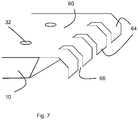
- the thermal transport members are shaped spring elements 60,62 held on to the base portion parts 14,16 by screws 32 to ensure good thermal contact to the base portion parts 14,16.
- the shaped spring elements 60,62 have elastic fingers 64 on their ends separated by notches 66 in the spring elements 60,62. Note that the shaping of the spring elements matches the shape of the intended hollow tube - i.e. the elastic fingers 64 are curved, to achieve good thermal contact to the tube over an extended area not merely a point.
- the size of the hollow tube or capillary may be varied depending on the sample. Indeed, it will be noted that the approach used does not require a capillary of a particular exact size. Different size frames 30 and thermal transport members 36 may allow for a wide variety of sizes of hollow tube.
- the hollow tube may be quartz or glass or any other material capable of holding a sample without interfering too much in the X-ray measurements.
- the thermal regulation system 24 may be used for heating or cooling as required.
- the base portion 10 may include a Peltier cell, heat-pipe or similar in order to transport heat from or to the base portion.
Landscapes
- Chemical & Material Sciences (AREA)
- Physics & Mathematics (AREA)
- Health & Medical Sciences (AREA)
- Life Sciences & Earth Sciences (AREA)
- Analytical Chemistry (AREA)
- Biochemistry (AREA)
- General Health & Medical Sciences (AREA)
- General Physics & Mathematics (AREA)
- Immunology (AREA)
- Pathology (AREA)
- Crystallography & Structural Chemistry (AREA)
- Analysing Materials By The Use Of Radiation (AREA)
Abstract
Description
- The invention relates to a sample holder for X-ray analysis and a method of making X-ray measurements using a sample holder.
- When carrying out X-ray analysis, such as X-ray diffraction (XRD) or X-ray fluorescence (XRF) analysis, there is a need to hold the sample in position in an X-ray beam. For some types of sample, existing sample holders do a good job.
- One type of sample holder holds the sample in a hollow sample holder which may be a capillary. The hollow sample holder can then be mounted in some form of mounting for introduction into X-ray analysis apparatus. The approach using a capillary can give the advantage that the capillary can be relatively low cost and so a new capillary can be used for each new sample, avoiding the need to completely clean the sample holder. Such an approach can therefore be useful for example where contamination from a previous sample could affect measurements.
- Such a sample holder may be of use in particular in small angle X-ray scattering (SAXS) measurements such as those proposed in
US 7,542,547 . - However, in some cases it is necessary to hold samples at a predetermined temperature for analysis. There is therefore a need for a temperature controlled sample holder.
- A sample holder for XRD analytical apparatus using a capillary as a sample holder and having a heater for heating the sample in use is taught by
US 8,597,598 . - However, the arrangement is complicated and does not allow for mounting inside existing equipment.
- There thus remains a need for a sample holder that can be thermally controlled to keep the sample at a required temperature that is straightforward to manufacture and use and preferably which can be mounted inside existing equipment.
- According to a first aspect of the invention, there is provided a sample holder for holding a hollow tube for X-ray analysis apparatus, comprising:
- a base portion having an opening for an X-ray beam;
- a first thermal transport member on the base portion on one lateral side of the opening and a second thermal transport member on the other lateral side of the opening;
- wherein the first and second thermal transport members are deformable to compress the hollow tube laterally to hold the hollow tube such that:
- (i) an X-ray beam can pass through the hollow tube without intersecting any part of the sample holder, and
- (ii) there is thermal contact between the hollow tube and the thermal transport member along the length of the hollow tube and around at least part of the circumference of the hollow tube to conduct heat between the hollow tube and the base portion through the thermal transport member.
- The inventor has discovered that a particular problem in obtaining an effective design for providing a tube-based sample holder, especially such a sample holder suitable for use in SAXS measurements, is obtaining effective thermal coupling to the hollow tube for holding the sample. One reason for this is that for high quality SAXS measurements the X-ray beam should not pass through parts of the sample holder except for the hollow tube to avoid signal from those other parts of the sample holder. This makes it difficult to arrive at effective thermal contact.
- By using a deformable material as the material of the thermal transport members, the tube may be releasably held, i.e. the tube may be supported only by the thermal transport member without requiring glue, screws or the like. The thermal transport members may be formed of a relatively soft material and/or an elastic material. By causing a lateral force between the thermal transport member and tube, by compressing the thermal transport member on introduction of the sample holder, either by a compression member or by the interaction of the tube itself with the thermal transport member the tube may be removed and replaced - the tube is not fixed with glue or other permanent mounting but instead is held between the deformable thermal transport members. This removability is achieved while still providing good thermal contact along the length of the capillary and also providing contact around a good portion of the circumference of the capillary.
- Such an arrangement provides a good thermal contact and good control of temperature compared with arrangements such as
US 8,597,598 using a radiant heater, while still allowing the tube to be easily removed and replaced. - The opening may be a longitudinal slit and the hollow sample holder may be accuately aligned with the longitudinal slit without requiring the tube to engage with the base nor requiring parts of the compression member or base part to intersect with X-ray beams passing through the longitudinal slit.
- The sample holder may further comprise a compression element for compressing the first and/or second thermal transport members to urge the first and second thermal transport members together to hold the hollow tube.
- The compression element may be arranged to compress the thermal transport members between the compression element and the base portion in the transverse direction to urge the edges of the first and second thermal transport members together, to hold the hollow tube in a longitudinal direction in the opening.
- The sample holder may further comprise channels in the base portion for passing cooling or heating fluid such as liquid or gas through the base portion. The compression element may conveniently include a plurality of screws passing at least partially through the frame and through the base portion.
- A Peltier cell may be integrated with the base portion to provide well-controlled temperature regulation.
- The compression member may comprise a second longitudinal slit aligned with the first longitudinal slit.
- The sample holder may further comprise a hollow tube held between the thermal transport members. The hollow tube may be a glass or quartz capillary.
- The thermal transport members may be permanently fixed to the base portion.
- The thermal transport members may be elastic, for example of thermally conductive plastics or thermally conductive rubber. Alternatively, the thermal transport member may be of carbon (graphite, pyrolytic highly oriented graphite, graphenic carbon or similar) or soft ductile metals such as (pure) aluminium, gallium or indium. Alternatively, the thermal transport members may be in the form of a metal spring.
- Another aspect of the invention relates to an X-ray apparatus for small angle X-ray scattering comprising:
- a sample holder as described above;
- an X-ray source for supplying an X-ray beam through the opening to a sample mounted in the hollow tube; and
- an X-ray detector arranged to detect X-rays scattered by a sample in the sample holder.
- Embodiments of the invention will now be described with reference to the accompanying diagrams, in which:
-
Figure 1 is a top view of a sample holder; -
Figure 2 is a section through the sample holder ofFigure 1 along A-A, -
Figure 3 is a section through an alternative sample holder; -
Figure 4 is a section through a further alternative sample holder; -
Figure 5 is a section though a further alternative sample holder; -
Figure 6 is a section through a yet further alternative sample holder; and -
Figure 7 is a perspective view of the sample holder ofFigure 6 . - Referring to
Figure 1 (top view) andFigure 2 (section) asample holder 2 has amounting end 4 and anoperation end 6. The mountingend 4 is arranged to be fixedly mounted in X-ray diffraction (XRD) apparatus (not shown) and includesmounting holes 8 adapted to the mount in the XRD apparatus. The skilled person will appreciate that different types of XRD apparatus will have different mounts and that the sample holder may be adapted accordingly. - The operation end of the
sample holder 6 has abase portion 10 having an opening in the form of alongitudinal slit 12 dividing thebase portion 10 into two longitudinally extendingbase portion parts longitudinal slit 12. This provides anX-ray path 18 transversely through thelongitudinal slit 12 as illustrated schematically by the arrow. Thebase portion 10 may be made, for example, of metal such as brass. As may be seen inFigure 1 , the longitudinal split does not extend for the whole length of the operational end, but only in a central region. - Each of the
base portion parts duct 20 likewise extending longitudinally for carrying a thermal fluid. The thermal liquid may be replaced by thermal gas. Theduct 20 communicates withfluid ports 22 on the mountingend 4 for connection to athermal regulation system 24. Theduct 20 thus forms part of a circulating system by which thermal fluid circulates from one of thefluid ports 22 through theduct 20 in one of thebase portion parts 14 towards theoperational end 6 and then returns through the duct in the other of thebase portion parts 16 to the otherfluid port 22 and back to thethermal regulation system 24. - A compression element in the form of a
frame 30 is provided which is fixed tobase portion 10 byscrews 32 engaging with screw holes 34 inbase portion 10. Twothermal transport members frame 30. A firstthermal transport member 36 is provided onbase portion part 14 and a secondthermal transport member 38 is provided on the otherbase portion part 16. Thescrews 32 act to urge theframe 30 transversely (vertically inFigure 2 ) to compress the thermal transport members transversely. - In use, a hollow tube in the form of
capillary 40 may be provided. The capillary 40 is mounted above the base portion of the sample holder between thethermal transport members frame 30 is then mounted on the top and thescrews 32 tightened to compress thethermal transport members frame 30. Since the thermal transport members have a bulk modulus this causes the side edges of thethermal transport members capillary 40 to be urged laterally together. This causes the material of the thermal transport member to laterally press against the sides of the capillary, in contact with the capillary over the length of the longitudinal slit as well as over a significant part of the capillary. In other words, the thermal transport members (as a pair) are not simply in contact with one or two single points around the circumference of the capillary but together cover a significant fraction of the circumference, for example at least 10% but preferably more, for example 20%, 30% or even more preferably 50%. - A
sample 42 is contained in the capillary 40. The capillary may be a single shot capillary with a small amount ofsample 42 mounted inside the capillary 40 before the capillary is mounted in thesample holder 2. - The temperature is set on
thermal regulation system 24 which urges thermal fluid such as water or other thermally conductive liquid throughfluid ports 22 andducts 20 which controls the temperature of thebase portion 10. Thethermal transport members base portion 10 and withcapillary 40 and so thesample 42 is maintained at the desired temperature. The temperature of the fluid is controlled by thethermal regulation system 40 to achieve a desired temperature of thesample 42. To this end, thermometers may be integrated intobase portion 10 and a feedback loop maintained. - A beam of X-rays are directed through
slit 12 ontosample 42 incapillary 40 and are diffracted by a small angle as indicated schematically by the arrow. The small angle of diffraction is measured. - In the embodiment described, the X-rays are used for small angle scattering. The X-rays are provided in the form of a line beam of X-rays travelling in the transverse direction along
X-ray path 18, the line beam extending in the longitudinal direction to match the opening in the form of thelongitudinal slit 12. Where the sample holder is for holding a sample with X-ray beams of different format, for example an X-ray beam in the form of a circular or square cross section, the shape of the opening can be adapted to match the shape of the intended beam. - Any suitable material may be adopted for
thermal transport members 36. In the specific embodiment described, the material used is a pyrolytic highly oriented graphite sheet, which is commercially available and which has a high thermal conductivity. Alternative materials are available - thermally conductive rubber or plastics may be used, as may be polymer loaded with conductive material. Alternatively, graphite or gallium may be used. The material used in this embodiment is softer than the materials used forframe 30 andbase 10 as well as having good thermal conductive properties. - The
thermal transport members - In the example shown above, the
compression element 30 is a single frame. In an alternative example shown inFigure 3 , two separate frame elements, afirst frame element 50, and asecond frame element 52, have the same function. Each may independently be urged transversely byscrews 32 to transversely compress thethermal transport members thermal transport members hollow tube 40 to both hold the hollow tube and to provide a good thermal path to the hollow tube. - Note that in this example, the diameter of the
hollow tube 40 is less than the gap between thethermal transport members thermal transport members screws 32 are tightened. - In an alternative embodiment, illustrated in
Figure 4 , with asingle frame 30, shown in a state with thehollow tube 40 not mounted, the diameter d of the hollow tube is greater than the gap g between the first and secondthermal transport members screws 32 untightened and no transverse pressure being exerted on thethermal transport members tube 40 can be mounted and held between thethermal transport members screws 32. Thescrews 32 only serve to hold thethermal transport members frame 30 and the base 10 to enable the sample holder to be disassembled, for example for cleaning. - By not requiring the screws to be tightened and untightened when mounting or dismounting the sample holder, the arrangement of
Figure 4 can speed up a sample change. - The
thermal transport members hollow tube 40 is removed. - In a further embodiment, illustratred in
Figure 5 , theframe 30 is omitted and thethermal transport members base portion parts thermal transport members hollow tube 40. - This provides a simple structure.
- Note that the use of glue to mount the
thermal transport members base portion parts - In a yet further example, illustrated in
Figures 6 and7 , the thermal transport members are shapedspring elements base portion parts screws 32 to ensure good thermal contact to thebase portion parts spring elements elastic fingers 64 on their ends separated bynotches 66 in thespring elements elastic fingers 64 are curved, to achieve good thermal contact to the tube over an extended area not merely a point. - The size of the hollow tube or capillary may be varied depending on the sample. Indeed, it will be noted that the approach used does not require a capillary of a particular exact size. Different size frames 30 and
thermal transport members 36 may allow for a wide variety of sizes of hollow tube. - The hollow tube may be quartz or glass or any other material capable of holding a sample without interfering too much in the X-ray measurements.
- The
thermal regulation system 24 may be used for heating or cooling as required. - Instead of the cooling arrangements with
ducts 20 as described above thebase portion 10 may include a Peltier cell, heat-pipe or similar in order to transport heat from or to the base portion. - Those skilled in the art will realise that the above embodiments are by way of example only and that features described with reference to one embodiment may also be applied to other embodiments.
Claims (15)
- A sample holder for holding a hollow tube for X-ray analysis apparatus, comprising:a base portion having an opening for an X-ray beam;a first thermal transport member on the base portion on one lateral side of the opening and a second thermal transport member on the other lateral side of the opening;wherein the first and second thermal transport members are deformable to compress the hollow tube laterally to hold the hollow tube such that:(i) an X-ray beam can pass through the hollow tube without intersecting any part of the sample holder, and(ii) there is thermal contact between the hollow tube and the thermal transport member along the length of the hollow tube and around at least part of the circumference of the hollow tube to conduct heat between the hollow tube and the base portion through the thermal transport member.
- A sample holder according to claim 1, further comprising a compression element for compressing the first and/or second thermal transport members to urge the first and second thermal transport members together to hold the hollow tube.
- A sample holder according to claim 2 wherein the compression element is arranged to compress the thermal transport members between the compression element and the base portion in the transverse direction to urge the edges of the first and second thermal transport members together, to hold the hollow tube extending in a longitudinal direction along the opening.
- A sample holder according to any preceding claim wherein the opening is a longitudinal slit.
- A sample holder according to any preceding claim further comprising channels in the base portion for containing cooling or heating fluid.
- A sample holder according to claim 2 wherein the thermal transport members are softer than the base portion and softer than the compression element.
- A sample holder according to claim 6 wherein the thermal transport members are elastic.
- A sample holder according to any preceding claim further comprising a plurality of screws passing at least partially through the compression member and through the base portion.
- A sample holder according to any preceding claim further comprising a Peltier cell or heat pipe integrated with the base portion.
- A sample holder according to any preceding claim holding a hollow tube in the form of a glass or quartz capillary.
- A sample holder according to any preceding claim wherein the thermal transport member is fixed to the base portion.
- A sample holder according to any preceding claim wherein the thermal transport members are of graphite or graphenic carbon, or aluminium, gallium, indium or an alloy thereof.
- A sample holder according to any any preceding claim, wherein the thermal transport members are in the form of a metal spring.
- An X-ray apparatus for small angle X-ray scattering comprising:a hollow tube for X-ray analysis apparatus;an X-ray source for supplying an X-ray beam through an opening to a sample mounted in the hollow tube; andan X-ray detector arranged to detect X-rays scattered a sample in the hollow tube; anda sample holder according to any preceding claim holding the hollow tube, wherein the said opening through which the X-ray beam is supplied is the opening in the base portion.
- An X-ray apparatus according to claim 14, wherein the X-ray detector is arranged to detect X-rays scattered by the sample by a small angle less than 8°.
Applications Claiming Priority (1)
| Application Number | Priority Date | Filing Date | Title |
|---|---|---|---|
| US15/214,575 US10359376B2 (en) | 2016-07-20 | 2016-07-20 | Sample holder for X-ray analysis |
Publications (2)
| Publication Number | Publication Date |
|---|---|
| EP3273229A1 true EP3273229A1 (en) | 2018-01-24 |
| EP3273229B1 EP3273229B1 (en) | 2023-05-31 |
Family
ID=59350713
Family Applications (1)
| Application Number | Title | Priority Date | Filing Date |
|---|---|---|---|
| EP17181192.0A Active EP3273229B1 (en) | 2016-07-20 | 2017-07-13 | Sample holder for an x-ray analysis apparatus |
Country Status (4)
| Country | Link |
|---|---|
| US (1) | US10359376B2 (en) |
| EP (1) | EP3273229B1 (en) |
| JP (1) | JP6701133B2 (en) |
| CN (1) | CN107643308B (en) |
Cited By (3)
| Publication number | Priority date | Publication date | Assignee | Title |
|---|---|---|---|---|
| CN109682849A (en) * | 2018-12-29 | 2019-04-26 | 中国科学院高能物理研究所 | A kind of small angle in situ measurement heating furnace synchronous with wide-angle x-ray scattering |
| GB2596061A (en) * | 2020-06-09 | 2021-12-22 | Nordson Corp | An x-ray inspection system, an x-ray imaging accessory, a sample support, a kit, and a method of using an x-ray inspection system |
| EP3885756A4 (en) * | 2018-11-23 | 2022-10-19 | Rigaku Corporation | OCCLUSION DEVICE AND METHOD FOR OCCLUSION OF SINGLE-CRYSTALLINE X-RAY STRUCTURAL ANALYSIS SAMPLE |
Families Citing this family (5)
| Publication number | Priority date | Publication date | Assignee | Title |
|---|---|---|---|---|
| EP3428629B1 (en) * | 2017-07-14 | 2022-12-07 | Malvern Panalytical B.V. | Analysis of x-ray spectra using curve fitting |
| US11231379B2 (en) * | 2017-08-04 | 2022-01-25 | Cornell University | Sample cell arrays and hardware for high-throughput cryoSAXS |
| NL2024445B1 (en) * | 2019-12-12 | 2021-09-01 | Delmic Ip B V | Method and manipulation device for handling samples |
| EP4147266A1 (en) * | 2020-05-05 | 2023-03-15 | Micromass UK Limited | A guide arrangement for a capillary holder |
| DE112023005742T5 (en) * | 2023-02-07 | 2025-12-31 | Nextron Corp. | XRD-USING MICROPROBE SYSTEM |
Citations (3)
| Publication number | Priority date | Publication date | Assignee | Title |
|---|---|---|---|---|
| DE102004029721A1 (en) * | 2003-06-24 | 2005-01-13 | Institut Français du Pétrole, Rueil-Malmaison | Powder analyzer by diffraction of X-rays |
| US7542547B2 (en) | 2007-01-19 | 2009-06-02 | Panalytical B.V. | X-ray diffraction equipment for X-ray scattering |
| US8597598B2 (en) | 2011-07-12 | 2013-12-03 | University Of Cape Town | Sample presentation device for radiation-based analytical equipment |
Family Cites Families (33)
| Publication number | Priority date | Publication date | Assignee | Title |
|---|---|---|---|---|
| SE319917B (en) * | 1968-05-29 | 1970-01-26 | Incentive Res & Dev Ab | |
| JPS5816553U (en) * | 1981-07-24 | 1983-02-01 | 理学電機株式会社 | Sample heating device for X-ray small-angle scattering measurement device |
| JPH06102208A (en) * | 1992-09-08 | 1994-04-15 | Rigaku Corp | Sample heating device for X-ray diffraction measurement |
| IL120429A (en) * | 1997-03-12 | 2000-09-28 | Jordan Valley Applied Radiation Ltd | X-ray fluorescence analyzer |
| DE19842797C1 (en) * | 1998-09-18 | 2000-01-27 | Max Planck Gesellschaft | Holder for crystalline samples and especially protein crystals |
| JP3666862B2 (en) * | 2002-06-19 | 2005-06-29 | 株式会社リガク | Ion exchange membrane evaluation method and organic substance evaluation method |
| JP3674006B2 (en) * | 2002-06-19 | 2005-07-20 | 株式会社リガク | Ion exchange membrane evaluation method and organic substance evaluation method |
| JP2004125582A (en) * | 2002-10-02 | 2004-04-22 | Rigaku Corp | Analysis device and analysis method |
| DE10359464A1 (en) * | 2003-12-17 | 2005-07-28 | Fraunhofer-Gesellschaft zur Förderung der angewandten Forschung e.V. | Method and device for generating in particular EUV radiation and / or soft X-radiation |
| JP2005221362A (en) * | 2004-02-05 | 2005-08-18 | Rigaku Corp | X-ray analyzer and sample analysis system |
| KR101063106B1 (en) * | 2004-11-08 | 2011-09-07 | 에스아이아이 나노 테크놀로지 가부시키가이샤 | Fluorescence X-ray Analyzer |
| JP4849957B2 (en) * | 2006-05-26 | 2012-01-11 | エスアイアイ・ナノテクノロジー株式会社 | X-ray fluorescence analyzer |
| CN101111118B (en) * | 2006-07-20 | 2011-03-02 | 中国科学院长春光学精密机械与物理研究所 | Stable liquid target laser plasma light source |
| JP5001741B2 (en) * | 2007-07-27 | 2012-08-15 | 住友電気工業株式会社 | Sample stage and sample analysis method |
| US20090101306A1 (en) * | 2007-10-22 | 2009-04-23 | Reis Bradley E | Heat Exchanger System |
| EP2534472B1 (en) * | 2010-02-08 | 2018-01-24 | Bruker AXS GmbH | A system for analyzing a granulate for producing a pharmaceutical product |
| AT511103B1 (en) * | 2011-03-17 | 2012-09-15 | Anton Paar Gmbh | METHOD AND DEVICE FOR STUDYING THE X-RAY PROPERTIES OF SAMPLES |
| FR2973879B1 (en) * | 2011-04-06 | 2013-11-29 | Univ Rouen | METHOD FOR MEASURING X-RAY DIFFRACTION, ITS APPLICATIONS AND DEVICE FOR IMPLEMENTING THE SAME |
| CN103534584B (en) * | 2011-05-17 | 2016-05-04 | 齐塔库比有限责任公司 | Method for detecting polymorphs using synchrotron radiation |
| CN110006936A (en) * | 2011-06-20 | 2019-07-12 | X射线光学系统公司 | The on-line monitoring of pollutant and its refinery's application in crude oil and heavy fuel |
| JP6001067B2 (en) * | 2011-07-05 | 2016-10-05 | ユニバーシティ・オブ・ケープ・タウンUniversity Of Cape Town | Sample holder for radiation-based analyzers |
| WO2013022626A1 (en) * | 2011-08-05 | 2013-02-14 | E.A. Fischione Instruments, Inc. | Improved cryogenic specimen holder |
| WO2013025682A2 (en) * | 2011-08-15 | 2013-02-21 | X-Ray Optical Systems, Inc. | Sample viscosity and flow control for heavy samples, and x-ray analysis applications thereof |
| US9275844B2 (en) * | 2012-05-16 | 2016-03-01 | The Board Of Trustees Of The Leland Stanford Junior University | Apparatus and method for nanoflow liquid jet and serial femtosecond x-ray protein crystallography |
| WO2013184665A1 (en) * | 2012-06-04 | 2013-12-12 | Cornell University | Apparatus and methods for low temperature small angle x-ray scattering |
| JP6353450B2 (en) * | 2012-09-07 | 2018-07-04 | カール・ツァイス・エックス−レイ・マイクロスコピー・インコーポレイテッドCarl Zeiss X−Ray Microscopy, Inc. | Confocal X-ray fluorescence / X-ray computed tomography combined system and method |
| JP5807967B2 (en) * | 2012-10-11 | 2015-11-10 | 株式会社リガク | X-ray analyzer |
| US9360440B2 (en) * | 2013-03-15 | 2016-06-07 | X-Ray Optical Systems, Inc. | Non-homogeneous sample handling apparatus and X-ray analyzer applications thereof |
| JP2015038435A (en) * | 2013-08-19 | 2015-02-26 | 株式会社東芝 | Radiation detector |
| EP2848924B1 (en) * | 2013-09-11 | 2016-08-24 | Anton Paar GmbH | Tempering chamber for compact x-ray apparatus |
| US9683950B2 (en) * | 2014-10-31 | 2017-06-20 | Olympus Scientific Solutions Americas Inc. | XRD sample handling apparatus |
| US10175184B2 (en) * | 2015-06-22 | 2019-01-08 | Moxtek, Inc. | XRF analyzer for light element detection |
| KR101750745B1 (en) * | 2016-01-22 | 2017-06-27 | 한국과학기술연구원 | Furnace for transmission mode x-ray diffractometer and transmission mode x-ray diffractometer using therof |
-
2016
- 2016-07-20 US US15/214,575 patent/US10359376B2/en active Active
-
2017
- 2017-07-13 EP EP17181192.0A patent/EP3273229B1/en active Active
- 2017-07-19 JP JP2017139554A patent/JP6701133B2/en active Active
- 2017-07-20 CN CN201710593858.7A patent/CN107643308B/en active Active
Patent Citations (3)
| Publication number | Priority date | Publication date | Assignee | Title |
|---|---|---|---|---|
| DE102004029721A1 (en) * | 2003-06-24 | 2005-01-13 | Institut Français du Pétrole, Rueil-Malmaison | Powder analyzer by diffraction of X-rays |
| US7542547B2 (en) | 2007-01-19 | 2009-06-02 | Panalytical B.V. | X-ray diffraction equipment for X-ray scattering |
| US8597598B2 (en) | 2011-07-12 | 2013-12-03 | University Of Cape Town | Sample presentation device for radiation-based analytical equipment |
Non-Patent Citations (1)
| Title |
|---|
| ANONYMOUS: "GCH25-75 Gas Cell Oven", 19 May 2010 (2010-05-19), XP055411168, Retrieved from the Internet <URL:https://www.thorlabs.com/drawings/1d91e8af276bf034-D5CF10CC-92C2-AA6A-6E14871368ECB5E2/GCH25-75-Manual.pdf> [retrieved on 20170928] * |
Cited By (5)
| Publication number | Priority date | Publication date | Assignee | Title |
|---|---|---|---|---|
| EP3885756A4 (en) * | 2018-11-23 | 2022-10-19 | Rigaku Corporation | OCCLUSION DEVICE AND METHOD FOR OCCLUSION OF SINGLE-CRYSTALLINE X-RAY STRUCTURAL ANALYSIS SAMPLE |
| CN109682849A (en) * | 2018-12-29 | 2019-04-26 | 中国科学院高能物理研究所 | A kind of small angle in situ measurement heating furnace synchronous with wide-angle x-ray scattering |
| CN109682849B (en) * | 2018-12-29 | 2020-07-17 | 中国科学院高能物理研究所 | Synchronous in-situ measurement heating furnace for small-angle and wide-angle X-ray scattering |
| GB2596061A (en) * | 2020-06-09 | 2021-12-22 | Nordson Corp | An x-ray inspection system, an x-ray imaging accessory, a sample support, a kit, and a method of using an x-ray inspection system |
| US12332189B2 (en) | 2020-06-09 | 2025-06-17 | Nordson Corporation | X-ray inspection system, an x-ray imaging accessory, a sample support, a kit, and a method of using an x-ray inspection system |
Also Published As
| Publication number | Publication date |
|---|---|
| JP2018013485A (en) | 2018-01-25 |
| CN107643308A (en) | 2018-01-30 |
| EP3273229B1 (en) | 2023-05-31 |
| CN107643308B (en) | 2022-04-15 |
| JP6701133B2 (en) | 2020-05-27 |
| US10359376B2 (en) | 2019-07-23 |
| US20180024081A1 (en) | 2018-01-25 |
Similar Documents
| Publication | Publication Date | Title |
|---|---|---|
| EP3273229B1 (en) | Sample holder for an x-ray analysis apparatus | |
| EP3450955B1 (en) | Adhesive testing systems and methods | |
| US10901196B2 (en) | Light microscope having a sample stage for cryomicroscopy | |
| JP6001067B2 (en) | Sample holder for radiation-based analyzers | |
| US9409169B2 (en) | Microfluidic card connection device | |
| US4591722A (en) | Low temperature stage for microanalysis | |
| EP2848924B1 (en) | Tempering chamber for compact x-ray apparatus | |
| CN106461521A (en) | Airflow diverter for reduced specimen temperature gradient | |
| US6637253B2 (en) | Hydrogen collection and detection | |
| US9103751B2 (en) | Device for transversely supporting a longitudinal test tube, and equipment for determining the mechanical bending properties of such a test tube | |
| CN118493489A (en) | Shearing equipment for segmentation of heat preservation pipeline | |
| CN107847901B (en) | Flow element with integrated capillary line for conveying fluid | |
| US10569436B2 (en) | Device for cutting hair | |
| US12174360B2 (en) | Imaging mechanism and sample analyzing apparatus provided with the same | |
| US9164047B2 (en) | Apparatus and method for supporting a liquid sample for measuring scattering of electromagnetic radiation | |
| Suzuki et al. | Shear cell development for diffusion experiments in FOTON-Satellite missions and on the ground with consideration of shear-induced convection | |
| CN111297525A (en) | Costal cartilage slicer | |
| DE202015102305U1 (en) | Experimental device for the investigation of heat conduction in specimens of metal or other material | |
| DE102010010694B4 (en) | Microtome with sample cooling | |
| CN102213637B (en) | Impact test device and impact test method | |
| CN221580668U (en) | Quick dismantlement formula micro-fluidic chip fixing device | |
| DE202013001062U1 (en) | material testing | |
| CN211553997U (en) | A sample container and an analytical testing instrument comprising the same | |
| CN205352970U (en) | Continuous attenuating device of synchrotron radiation X light | |
| JP2024020957A (en) | Chamber, analyzer and analysis method |
Legal Events
| Date | Code | Title | Description |
|---|---|---|---|
| PUAI | Public reference made under article 153(3) epc to a published international application that has entered the european phase |
Free format text: ORIGINAL CODE: 0009012 |
|
| STAA | Information on the status of an ep patent application or granted ep patent |
Free format text: STATUS: THE APPLICATION HAS BEEN PUBLISHED |
|
| AK | Designated contracting states |
Kind code of ref document: A1 Designated state(s): AL AT BE BG CH CY CZ DE DK EE ES FI FR GB GR HR HU IE IS IT LI LT LU LV MC MK MT NL NO PL PT RO RS SE SI SK SM TR |
|
| AX | Request for extension of the european patent |
Extension state: BA ME |
|
| RAP1 | Party data changed (applicant data changed or rights of an application transferred) |
Owner name: MALVERN PANALYTICAL B.V. |
|
| STAA | Information on the status of an ep patent application or granted ep patent |
Free format text: STATUS: REQUEST FOR EXAMINATION WAS MADE |
|
| 17P | Request for examination filed |
Effective date: 20180716 |
|
| RBV | Designated contracting states (corrected) |
Designated state(s): AL AT BE BG CH CY CZ DE DK EE ES FI FR GB GR HR HU IE IS IT LI LT LU LV MC MK MT NL NO PL PT RO RS SE SI SK SM TR |
|
| STAA | Information on the status of an ep patent application or granted ep patent |
Free format text: STATUS: EXAMINATION IS IN PROGRESS |
|
| 17Q | First examination report despatched |
Effective date: 20190214 |
|
| GRAP | Despatch of communication of intention to grant a patent |
Free format text: ORIGINAL CODE: EPIDOSNIGR1 |
|
| STAA | Information on the status of an ep patent application or granted ep patent |
Free format text: STATUS: GRANT OF PATENT IS INTENDED |
|
| RIC1 | Information provided on ipc code assigned before grant |
Ipc: G01N 23/207 20180101ALI20221118BHEP Ipc: G01N 23/20033 20180101ALI20221118BHEP Ipc: G01N 23/201 20180101ALI20221118BHEP Ipc: G01N 23/20 20180101AFI20221118BHEP |
|
| INTG | Intention to grant announced |
Effective date: 20221207 |
|
| GRAS | Grant fee paid |
Free format text: ORIGINAL CODE: EPIDOSNIGR3 |
|
| GRAA | (expected) grant |
Free format text: ORIGINAL CODE: 0009210 |
|
| STAA | Information on the status of an ep patent application or granted ep patent |
Free format text: STATUS: THE PATENT HAS BEEN GRANTED |
|
| AK | Designated contracting states |
Kind code of ref document: B1 Designated state(s): AL AT BE BG CH CY CZ DE DK EE ES FI FR GB GR HR HU IE IS IT LI LT LU LV MC MK MT NL NO PL PT RO RS SE SI SK SM TR |
|
| REG | Reference to a national code |
Ref country code: GB Ref legal event code: FG4D Ref country code: CH Ref legal event code: EP |
|
| REG | Reference to a national code |
Ref country code: DE Ref legal event code: R096 Ref document number: 602017069169 Country of ref document: DE |
|
| REG | Reference to a national code |
Ref country code: AT Ref legal event code: REF Ref document number: 1571206 Country of ref document: AT Kind code of ref document: T Effective date: 20230615 |
|
| REG | Reference to a national code |
Ref country code: IE Ref legal event code: FG4D |
|
| REG | Reference to a national code |
Ref country code: NL Ref legal event code: FP |
|
| P01 | Opt-out of the competence of the unified patent court (upc) registered |
Effective date: 20230727 |
|
| REG | Reference to a national code |
Ref country code: LT Ref legal event code: MG9D |
|
| REG | Reference to a national code |
Ref country code: AT Ref legal event code: MK05 Ref document number: 1571206 Country of ref document: AT Kind code of ref document: T Effective date: 20230531 |
|
| PG25 | Lapsed in a contracting state [announced via postgrant information from national office to epo] |
Ref country code: SE Free format text: LAPSE BECAUSE OF FAILURE TO SUBMIT A TRANSLATION OF THE DESCRIPTION OR TO PAY THE FEE WITHIN THE PRESCRIBED TIME-LIMIT Effective date: 20230531 Ref country code: NO Free format text: LAPSE BECAUSE OF FAILURE TO SUBMIT A TRANSLATION OF THE DESCRIPTION OR TO PAY THE FEE WITHIN THE PRESCRIBED TIME-LIMIT Effective date: 20230831 Ref country code: ES Free format text: LAPSE BECAUSE OF FAILURE TO SUBMIT A TRANSLATION OF THE DESCRIPTION OR TO PAY THE FEE WITHIN THE PRESCRIBED TIME-LIMIT Effective date: 20230531 Ref country code: AT Free format text: LAPSE BECAUSE OF FAILURE TO SUBMIT A TRANSLATION OF THE DESCRIPTION OR TO PAY THE FEE WITHIN THE PRESCRIBED TIME-LIMIT Effective date: 20230531 |
|
| PG25 | Lapsed in a contracting state [announced via postgrant information from national office to epo] |
Ref country code: RS Free format text: LAPSE BECAUSE OF FAILURE TO SUBMIT A TRANSLATION OF THE DESCRIPTION OR TO PAY THE FEE WITHIN THE PRESCRIBED TIME-LIMIT Effective date: 20230531 Ref country code: PL Free format text: LAPSE BECAUSE OF FAILURE TO SUBMIT A TRANSLATION OF THE DESCRIPTION OR TO PAY THE FEE WITHIN THE PRESCRIBED TIME-LIMIT Effective date: 20230531 Ref country code: LV Free format text: LAPSE BECAUSE OF FAILURE TO SUBMIT A TRANSLATION OF THE DESCRIPTION OR TO PAY THE FEE WITHIN THE PRESCRIBED TIME-LIMIT Effective date: 20230531 Ref country code: LT Free format text: LAPSE BECAUSE OF FAILURE TO SUBMIT A TRANSLATION OF THE DESCRIPTION OR TO PAY THE FEE WITHIN THE PRESCRIBED TIME-LIMIT Effective date: 20230531 Ref country code: IS Free format text: LAPSE BECAUSE OF FAILURE TO SUBMIT A TRANSLATION OF THE DESCRIPTION OR TO PAY THE FEE WITHIN THE PRESCRIBED TIME-LIMIT Effective date: 20230930 Ref country code: HR Free format text: LAPSE BECAUSE OF FAILURE TO SUBMIT A TRANSLATION OF THE DESCRIPTION OR TO PAY THE FEE WITHIN THE PRESCRIBED TIME-LIMIT Effective date: 20230531 Ref country code: GR Free format text: LAPSE BECAUSE OF FAILURE TO SUBMIT A TRANSLATION OF THE DESCRIPTION OR TO PAY THE FEE WITHIN THE PRESCRIBED TIME-LIMIT Effective date: 20230901 |
|
| PG25 | Lapsed in a contracting state [announced via postgrant information from national office to epo] |
Ref country code: FI Free format text: LAPSE BECAUSE OF FAILURE TO SUBMIT A TRANSLATION OF THE DESCRIPTION OR TO PAY THE FEE WITHIN THE PRESCRIBED TIME-LIMIT Effective date: 20230531 |
|
| PG25 | Lapsed in a contracting state [announced via postgrant information from national office to epo] |
Ref country code: SK Free format text: LAPSE BECAUSE OF FAILURE TO SUBMIT A TRANSLATION OF THE DESCRIPTION OR TO PAY THE FEE WITHIN THE PRESCRIBED TIME-LIMIT Effective date: 20230531 |
|
| PG25 | Lapsed in a contracting state [announced via postgrant information from national office to epo] |
Ref country code: SM Free format text: LAPSE BECAUSE OF FAILURE TO SUBMIT A TRANSLATION OF THE DESCRIPTION OR TO PAY THE FEE WITHIN THE PRESCRIBED TIME-LIMIT Effective date: 20230531 Ref country code: SK Free format text: LAPSE BECAUSE OF FAILURE TO SUBMIT A TRANSLATION OF THE DESCRIPTION OR TO PAY THE FEE WITHIN THE PRESCRIBED TIME-LIMIT Effective date: 20230531 Ref country code: RO Free format text: LAPSE BECAUSE OF FAILURE TO SUBMIT A TRANSLATION OF THE DESCRIPTION OR TO PAY THE FEE WITHIN THE PRESCRIBED TIME-LIMIT Effective date: 20230531 Ref country code: PT Free format text: LAPSE BECAUSE OF FAILURE TO SUBMIT A TRANSLATION OF THE DESCRIPTION OR TO PAY THE FEE WITHIN THE PRESCRIBED TIME-LIMIT Effective date: 20231002 Ref country code: EE Free format text: LAPSE BECAUSE OF FAILURE TO SUBMIT A TRANSLATION OF THE DESCRIPTION OR TO PAY THE FEE WITHIN THE PRESCRIBED TIME-LIMIT Effective date: 20230531 Ref country code: DK Free format text: LAPSE BECAUSE OF FAILURE TO SUBMIT A TRANSLATION OF THE DESCRIPTION OR TO PAY THE FEE WITHIN THE PRESCRIBED TIME-LIMIT Effective date: 20230531 Ref country code: CZ Free format text: LAPSE BECAUSE OF FAILURE TO SUBMIT A TRANSLATION OF THE DESCRIPTION OR TO PAY THE FEE WITHIN THE PRESCRIBED TIME-LIMIT Effective date: 20230531 |
|
| PG25 | Lapsed in a contracting state [announced via postgrant information from national office to epo] |
Ref country code: MC Free format text: LAPSE BECAUSE OF FAILURE TO SUBMIT A TRANSLATION OF THE DESCRIPTION OR TO PAY THE FEE WITHIN THE PRESCRIBED TIME-LIMIT Effective date: 20230531 |
|
| PG25 | Lapsed in a contracting state [announced via postgrant information from national office to epo] |
Ref country code: MC Free format text: LAPSE BECAUSE OF FAILURE TO SUBMIT A TRANSLATION OF THE DESCRIPTION OR TO PAY THE FEE WITHIN THE PRESCRIBED TIME-LIMIT Effective date: 20230531 |
|
| REG | Reference to a national code |
Ref country code: DE Ref legal event code: R097 Ref document number: 602017069169 Country of ref document: DE |
|
| REG | Reference to a national code |
Ref country code: BE Ref legal event code: MM Effective date: 20230731 |
|
| PG25 | Lapsed in a contracting state [announced via postgrant information from national office to epo] |
Ref country code: LU Free format text: LAPSE BECAUSE OF NON-PAYMENT OF DUE FEES Effective date: 20230713 |
|
| PG25 | Lapsed in a contracting state [announced via postgrant information from national office to epo] |
Ref country code: LU Free format text: LAPSE BECAUSE OF NON-PAYMENT OF DUE FEES Effective date: 20230713 |
|
| PLBE | No opposition filed within time limit |
Free format text: ORIGINAL CODE: 0009261 |
|
| STAA | Information on the status of an ep patent application or granted ep patent |
Free format text: STATUS: NO OPPOSITION FILED WITHIN TIME LIMIT |
|
| REG | Reference to a national code |
Ref country code: IE Ref legal event code: MM4A |
|
| PG25 | Lapsed in a contracting state [announced via postgrant information from national office to epo] |
Ref country code: SI Free format text: LAPSE BECAUSE OF FAILURE TO SUBMIT A TRANSLATION OF THE DESCRIPTION OR TO PAY THE FEE WITHIN THE PRESCRIBED TIME-LIMIT Effective date: 20230531 |
|
| 26N | No opposition filed |
Effective date: 20240301 |
|
| PG25 | Lapsed in a contracting state [announced via postgrant information from national office to epo] |
Ref country code: SI Free format text: LAPSE BECAUSE OF FAILURE TO SUBMIT A TRANSLATION OF THE DESCRIPTION OR TO PAY THE FEE WITHIN THE PRESCRIBED TIME-LIMIT Effective date: 20230531 Ref country code: IT Free format text: LAPSE BECAUSE OF FAILURE TO SUBMIT A TRANSLATION OF THE DESCRIPTION OR TO PAY THE FEE WITHIN THE PRESCRIBED TIME-LIMIT Effective date: 20230531 Ref country code: BE Free format text: LAPSE BECAUSE OF NON-PAYMENT OF DUE FEES Effective date: 20230731 |
|
| PG25 | Lapsed in a contracting state [announced via postgrant information from national office to epo] |
Ref country code: IE Free format text: LAPSE BECAUSE OF NON-PAYMENT OF DUE FEES Effective date: 20230713 |
|
| PG25 | Lapsed in a contracting state [announced via postgrant information from national office to epo] |
Ref country code: IE Free format text: LAPSE BECAUSE OF NON-PAYMENT OF DUE FEES Effective date: 20230713 |
|
| PG25 | Lapsed in a contracting state [announced via postgrant information from national office to epo] |
Ref country code: BG Free format text: LAPSE BECAUSE OF FAILURE TO SUBMIT A TRANSLATION OF THE DESCRIPTION OR TO PAY THE FEE WITHIN THE PRESCRIBED TIME-LIMIT Effective date: 20230531 |
|
| PG25 | Lapsed in a contracting state [announced via postgrant information from national office to epo] |
Ref country code: BG Free format text: LAPSE BECAUSE OF FAILURE TO SUBMIT A TRANSLATION OF THE DESCRIPTION OR TO PAY THE FEE WITHIN THE PRESCRIBED TIME-LIMIT Effective date: 20230531 |
|
| PG25 | Lapsed in a contracting state [announced via postgrant information from national office to epo] |
Ref country code: CY Free format text: LAPSE BECAUSE OF FAILURE TO SUBMIT A TRANSLATION OF THE DESCRIPTION OR TO PAY THE FEE WITHIN THE PRESCRIBED TIME-LIMIT; INVALID AB INITIO Effective date: 20170713 |
|
| PG25 | Lapsed in a contracting state [announced via postgrant information from national office to epo] |
Ref country code: HU Free format text: LAPSE BECAUSE OF FAILURE TO SUBMIT A TRANSLATION OF THE DESCRIPTION OR TO PAY THE FEE WITHIN THE PRESCRIBED TIME-LIMIT; INVALID AB INITIO Effective date: 20170713 |
|
| PGFP | Annual fee paid to national office [announced via postgrant information from national office to epo] |
Ref country code: DE Payment date: 20250620 Year of fee payment: 9 |
|
| PGFP | Annual fee paid to national office [announced via postgrant information from national office to epo] |
Ref country code: CH Payment date: 20250801 Year of fee payment: 9 |
|
| PG25 | Lapsed in a contracting state [announced via postgrant information from national office to epo] |
Ref country code: TR Free format text: LAPSE BECAUSE OF FAILURE TO SUBMIT A TRANSLATION OF THE DESCRIPTION OR TO PAY THE FEE WITHIN THE PRESCRIBED TIME-LIMIT Effective date: 20230531 |
|
| PGFP | Annual fee paid to national office [announced via postgrant information from national office to epo] |
Ref country code: GB Payment date: 20260618 Year of fee payment: 10 |
|
| PGFP | Annual fee paid to national office [announced via postgrant information from national office to epo] |
Ref country code: NL Payment date: 20260622 Year of fee payment: 10 |
|
| PGFP | Annual fee paid to national office [announced via postgrant information from national office to epo] |
Ref country code: FR Payment date: 20260619 Year of fee payment: 10 |
|
| REG | Reference to a national code |
Ref country code: CH Ref legal event code: U11 Free format text: ST27 STATUS EVENT CODE: U-0-0-U10-U11 (AS PROVIDED BY THE NATIONAL OFFICE) Effective date: 20260801 |