US10901196B2 - Light microscope having a sample stage for cryomicroscopy - Google Patents
Light microscope having a sample stage for cryomicroscopy Download PDFInfo
- Publication number
- US10901196B2 US10901196B2 US15/329,704 US201515329704A US10901196B2 US 10901196 B2 US10901196 B2 US 10901196B2 US 201515329704 A US201515329704 A US 201515329704A US 10901196 B2 US10901196 B2 US 10901196B2
- Authority
- US
- United States
- Prior art keywords
- holder
- cover
- sample
- cutout
- light microscope
- Prior art date
- Legal status (The legal status is an assumption and is not a legal conclusion. Google has not performed a legal analysis and makes no representation as to the accuracy of the status listed.)
- Active, expires
Links
Images


Classifications
-
- G—PHYSICS
- G02—OPTICS
- G02B—OPTICAL ELEMENTS, SYSTEMS OR APPARATUS
- G02B21/00—Microscopes
- G02B21/24—Base structure
- G02B21/28—Base structure with cooling device
-
- G—PHYSICS
- G02—OPTICS
- G02B—OPTICAL ELEMENTS, SYSTEMS OR APPARATUS
- G02B21/00—Microscopes
- G02B21/34—Microscope slides, e.g. mounting specimens on microscope slides
-
- G—PHYSICS
- G02—OPTICS
- G02B—OPTICAL ELEMENTS, SYSTEMS OR APPARATUS
- G02B21/00—Microscopes
- G02B21/02—Objectives
-
- G—PHYSICS
- G02—OPTICS
- G02B—OPTICAL ELEMENTS, SYSTEMS OR APPARATUS
- G02B21/00—Microscopes
- G02B21/24—Base structure
- G02B21/26—Stages; Adjusting means therefor
Definitions
- the invention relates to a light microscope for cryomicroscopy, encompassing at least an objective and a sample stage having a cutout for a holder, coolable on the microscope, for a sample carrier mount, the cutout being covered by a cover.
- Cryofixation is a sample preparation method often used in electron microscopy. In this, a water-containing sample is frozen very rapidly to a temperature below ⁇ 150° C. (cryofixed), i.e. it is cooled very quickly in order to avoid the formation of ice crystals. Cryofixation has proven to be particularly suitable for investigations of structural biology.
- the specimens to be investigated for example cells, enzymes, viruses, or lipid layers, are thereby embedded in a thin, vitrified layer of ice.
- the great advantage of cryofixation is that the biological structures can be maintained in their natural state.
- a biological process can be halted at an arbitrary point in time by cryofixation and investigated in that vitrified state, for example using a cryo-electron microscope but also in a light microscope with corresponding sample cooling; cryo-light microscopy serves principally for ascertaining relevant regions in the sample, those regions being noted and then viewed in more detail in a cryo-electron microscope.
- the frozen samples which as a rule are located on an electron microscopy sample carrier known per se, for example a grid or a pin for scanning electron microscopy, must be conveyed, under the aforesaid cryogenic conditions and with water excluded, into corresponding sample carrier mounts that can then be conveyed into appropriate holders in the aforesaid microscopes.
- An electron microscopy sample carrier known per se, for example a grid or a pin for scanning electron microscopy
- a typical sample carrier mount for use in conjunction with the present invention has been disclosed, for example, in the document U.S. Pat. No. 8,395,130 B2, in which a grid that serves as a sample carrier and carries the cryogenic sample can be secured with clip elements in a corresponding mount.
- liquid nitrogen is made available, for example, in a Styrofoam container, in which container the necessary manipulation steps for conveying the grid into the sample carrier mounts were accomplished.
- the formation of cryogenic nitrogen gas from the liquid nitrogen on the one hand ensures the necessary low temperature and on the other hand creates an anhydrous atmosphere, so that contamination of the samples with water, and consequently with ice crystals, is prevented.
- cryofixation device for example cryofixation device, freeze fracture apparatus, or coating apparatus
- analytical devices here especially a cryo-light microscope and cryo-electron microscope.
- One vacuum cryo-transfer system is represented, for example, by the “Leica EM VCT100” system of the manufacturer Leica Microsystems, with which a sample carrier mount can be removed from a liquid nitrogen-cooled manipulation container and conveyed into the observation chamber, likewise cooled with liquid nitrogen, of an electron microscope.
- a sample carrier mount could also be transferred with such an apparatus into the cooled sample stage of a cryo-light microscope. It is self-evident to one skilled in the art that the term “coolable” in conjunction with the present invention means that the components referred to as “coolable” are coolable using special cooling systems that are provided on the microscope or attached to it in order to ensure cooling of the cryogenic samples during observation through the microscope.
- sample preparation for cryomicroscopy considerable effort is expended in order to avoid contamination of the sample with water and consequently with ice crystals.
- this must also be ensured after transfer of the sample or sample carrier or sample carrier mount into the working region of a cryo-light microscope; sample stages for light microscopes, which comprise a cutout in which a coolable holder for a sample carrier mount is located, are available for this purpose in the existing art.
- the cutout is supplied or flushed with liquid nitrogen or with cryogenic nitrogen gas, the cutout being covered with a cover in order to limit nitrogen consumption and prevent the entry of moisture from the air; in this, a slight overpressure is established by the nitrogen gas that is delivered or is produced from the liquid nitrogen, so that ambient air is forced out of the cutout and prevented from flowing in.
- the cover is transparent, since it is located in the beam path of the light microscope. The objective of the light microscope can be brought in, however, only until it is directly against the cover, thus producing a not insignificant spacing between the objective and the sample, which in turn results in a small aperture and, associated therewith, low resolution.
- the object on which the invention is based is therefore that of overcoming the disadvantages of the existing art in cryo-light microscopy and enabling a large aperture for viewing while reliably shielding the sample from moisture.
- a light microscope of the kind recited previously is refined according to the present invention in such a way that the sample stage is displaceable in two horizontal directions; that the cover rests floatingly on the sample stage; and that the objective passes through a cutout, corresponding to the objective, in the cover. Thanks to the floating mounting of the cover, the horizontal displaceability of the sample stage can be retained even through the objective passes through the cover in order to bring the objective directly against the sample so as to achieve a large aperture.
- the cutout in the cover is a circular hole whose diameter is less than 2 mm larger than the diameter of that part of the objective which is to be brought through the cover.
- a cooled holder for a sample carrier mount is arranged in a cutout of the sample stage.
- the light microscope according to the present invention is preferably refined in such a way that the sample stage is coolable. The result is that the environment of the sample is also reliably cooled, and the desired state of the sample is continuously maintained.
- the sample stage and/or the holder for a sample carrier mount preferably have a nitrogen internal cooling system.
- a cooling system of this kind is based on directing liquid or cryogenic gaseous nitrogen through a corresponding cooling conduit in the interior of the relevant parts, thereby resulting in highly efficient cooling of those parts.
- the cooling system can be exactly regulated by way of the flow rate of the nitrogen and an electric heating system.
- the sample stage preferably has an opening for delivery of a sample carrier mount to the holder for a sample carrier mount.
- Such an opening is preferably provided laterally on the sample stage, and allows insertion of a sample or a sample carrier mount into the sample stage.
- the invention is preferably refined in such a way that the opening for delivery of a sample carrier mount is closable by means of a closure device.
- the closure device can preferably be configured as a slider, a flap, or the like.
- the invention is therefore preferably refined in such a way that the cover comprises a transparent double panel.
- the transparency makes it possible to see through the cover, while the provision of a double panel prevents undesired condensation problems due to the temperature difference between the interior of the sample stage and the environment.
- FIG. 1 is an overall view of a cryo-light microscope according to the present invention
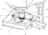
- FIG. 2 is a perspective depiction of the sample stage of the cryo-light microscope according to the present invention, without the cover of the cutout in the sample stage;
- FIG. 3 is a perspective depiction of the sample stage of the cryo-light microscope according to the present invention, with the cover of the cutout in the sample stage;
- FIG. 4 is a partial section view of passage of the objective through the cover.
- FIG. 5 is a partial section view of the holder for a sample carrier mount.
- the number 1 designates a cryo-light microscope according to the present invention that encompasses, inter alia, an objective 2 and a sample stage 3 .
- Sample stage 3 can be displaced not only vertically but also in two horizontal directions in accordance with arrows 4 , in order to ascertain relevant regions of a sample in sample stage 3 .
- the sample stage possesses an opening 5 for delivery of a sample carrier mount to holder 8 for a sample carrier mount, which is depicted in FIG. 2 .
- a cover 6 rests floatingly on sample stage 3 and can therefore be freely displaced thereon.
- Objective 2 is guided through the cutout in cover 6 and carries it along upon displacement of sample stage 3 in the direction of arrows 4 .
- Cover 6 encompasses a transparent double panel 6 ′.
- FIG. 2 shows a cutout 7 in sample stage 3 , in which cutout a holder 8 for a sample carrier mount is located.
- Holder 8 for a sample carrier mount possesses clip elements 9 that serve for clamping immobilization of a sample carrier mount (not depicted).
- Holder 8 for a sample carrier mount possesses an infeed 10 and an outlet 10 ′ for cryogenic nitrogen, so that holder 8 for a sample carrier mount can be cooled. This is described in further detail in conjunction with FIG. 5 .
- FIG. 2 furthermore shows opening 5 for delivery of a sample carrier mount.
- a closure device 11 for closing off opening 5 is embodied in the form of a slider 11 .
- FIG. 3 now shows that cover 6 completely covers cutout 7 in sample stage 3 in order to minimize the entry of moisture from the environment.
- Cutout 12 in cover 6 allows objective 2 , depicted in FIG. 1 , to be guided through the plane of cover 6 and thus to be brought directly against the sample in holder 8 for a sample carrier mount.
- a sleeve 13 is placed on cutout 12 and further enhances the sealing effect between objective 2 and cover 6 . Because cover 6 rests floatingly on sample stage 3 , it can readily be carried along by objective 2 and thus displaced on sample stage 3 .
- FIG. 4 shows the passage of objective 2 through cutout 12 .
- Sleeve 13 rests more or less against objective 2 and thereby enhances the sealing effect between objective 2 and cover 6 . It is further evident from FIG. 4 that cover 6 possesses a double panel 6 ′ in order to forestall condensation problems.
- a nitrogen conduit 14 is guided through infeed 10 so that cryogenic liquid nitrogen can be guided into cooling conduit 15 of holder 8 for a sample carrier mount.
- Cooling conduit 15 has an open end 16 onto which a metal frit element is placed. Nitrogen leaves cutout 7 through outlet 10 ′.
- the above-described nitrogen internal cooling system in holder 8 for a sample carrier mount ensures reliable cooling of the samples, and forces out ambient moisture.
Landscapes
- Physics & Mathematics (AREA)
- Chemical & Material Sciences (AREA)
- Analytical Chemistry (AREA)
- General Physics & Mathematics (AREA)
- Optics & Photonics (AREA)
- Sampling And Sample Adjustment (AREA)
- Microscoopes, Condenser (AREA)
Abstract
Description
-
- 1 Cryo-light microscope
- 2 Objective
- 3 Sample stage
- 4 Arrows
- 5 Opening
- 6 Cover
- 6′ Transparent double panel
- 7 Cutout
- 8 Sample holder
- 9 Clip elements
- 10 Infeed
- 10′ Outlet
- 11 Closure device/slider
- 12 Cutout
- 13 Sleeve
- 14 Nitrogen conduit
- 15 Cooling conduit
- 16 Open end
- 17 Metal frit element
Claims (8)
Applications Claiming Priority (4)
| Application Number | Priority Date | Filing Date | Title |
|---|---|---|---|
| DE102014110723.3 | 2014-07-29 | ||
| DE102014110723 | 2014-07-29 | ||
| DE102014110723 | 2014-07-29 | ||
| PCT/EP2015/066105 WO2016016000A1 (en) | 2014-07-29 | 2015-07-15 | Light microscope having a sample stage for cryomicroscopy |
Publications (2)
| Publication Number | Publication Date |
|---|---|
| US20170227752A1 US20170227752A1 (en) | 2017-08-10 |
| US10901196B2 true US10901196B2 (en) | 2021-01-26 |
Family
ID=53546634
Family Applications (1)
| Application Number | Title | Priority Date | Filing Date |
|---|---|---|---|
| US15/329,704 Active 2035-09-17 US10901196B2 (en) | 2014-07-29 | 2015-07-15 | Light microscope having a sample stage for cryomicroscopy |
Country Status (6)
| Country | Link |
|---|---|
| US (1) | US10901196B2 (en) |
| EP (1) | EP3175279B1 (en) |
| JP (1) | JP6498273B2 (en) |
| CN (1) | CN106662735B (en) |
| AU (2) | AU2015295666A1 (en) |
| WO (1) | WO2016016000A1 (en) |
Families Citing this family (11)
| Publication number | Priority date | Publication date | Assignee | Title |
|---|---|---|---|---|
| CN108572185B (en) * | 2017-03-13 | 2024-07-26 | 中国科学院兰州化学物理研究所 | Low-temperature microscopic sample loading system for easily-weathered crystals of X-ray single crystal diffractometer |
| GB201704275D0 (en) | 2017-03-17 | 2017-05-03 | Science And Tech Facilities Council | Super-resolution microscopy |
| EP3385771B1 (en) | 2017-04-05 | 2023-10-25 | Leica Mikrosysteme GmbH | Holding device for a sample holder and method for introducing and removing of a sample holder |
| NL2019247B1 (en) * | 2017-07-14 | 2019-01-28 | Hennyz B V | Cryotransfer system |
| CN110794566B (en) * | 2018-08-01 | 2021-09-07 | 深圳华大生命科学研究院 | Positioning device, optical imaging system and assembling method thereof |
| CN110164744B (en) * | 2019-05-17 | 2024-04-16 | 中国科学院理化技术研究所 | Scanning electron microscope refrigerating system and method based on low-temperature solid cooling |
| EP4105706A1 (en) | 2021-06-17 | 2022-12-21 | Leica Mikrosysteme GmbH | Method for correlative microscopy |
| EP4160162B1 (en) | 2021-09-30 | 2024-07-10 | LEICA Mikrosysteme GmbH | Control system for a liquid filling level and microscope stage including such a system |
| KR102511566B1 (en) * | 2022-02-16 | 2023-03-17 | 주식회사 큐리오시스 | Stage assembly with vent structure to prevent condensation |
| CN115586163A (en) * | 2022-08-23 | 2023-01-10 | 北京大学 | A cold stage for laser scanning microscope fluorescence observation and its application method |
| CZ202331A3 (en) * | 2023-01-27 | 2024-08-28 | Ústav molekulární genetiky AV ČR, v. v. i. | A table for correlative microscopy and a method of cryogenic fixation of the sample during simultaneous observation with a microscope |
Citations (19)
| Publication number | Priority date | Publication date | Assignee | Title |
|---|---|---|---|---|
| DE2210442A1 (en) | 1972-03-03 | 1973-09-06 | Remy Ernst Dr | MICROSCOPE ARRANGEMENT FOR THE EXAMINATION OF REFRIGERATED SPECIMENS, WITH AN BETWEEN MICROSCOPE LENS AND SAMPLE OR. SAMPLE COVER ARRANGED IMMERSION LIQUID |
| US3969013A (en) | 1974-03-26 | 1976-07-13 | Agence Nationale De Valorisation De La Recherche (Anvar) | Thermally controlled microscope stage assembly |
| SU1016641A1 (en) | 1982-01-08 | 1983-05-07 | Специальное Конструкторско-Технологическое Бюро С Опытным Производством Института Проблем Криобиологии И Криомедицины Ан Укрсср | Device for microscopic investigations of objects |
| JPS62125211A (en) | 1985-11-27 | 1987-06-06 | Sanki Kogyo Kk | Safety device for welding |
| JPH0277842U (en) | 1988-12-02 | 1990-06-14 | ||
| US5048300A (en) * | 1989-05-26 | 1991-09-17 | Reichert-Jung Optische Werke A.G. | Microtome cooling chamber and method of adjusting the cooling chamber temperature |
| JPH04213404A (en) | 1990-12-10 | 1992-08-04 | Nippon Telegr & Teleph Corp <Ntt> | light irradiation device |
| US5257128A (en) | 1988-06-22 | 1993-10-26 | Board Of Regents, The University Of Texas System | Freezing/perfusion microscope stage |
| JP2004141143A (en) | 2002-08-28 | 2004-05-20 | Tokai Hit:Kk | Culturing container for microscopic observation |
| US20060141613A1 (en) | 2004-12-28 | 2006-06-29 | Olympus Corporation | Culture observation apparatus |
| DE102005051386A1 (en) | 2005-10-27 | 2007-05-03 | Forschungszentrum Rossendorf E.V. | additional microscope |
| US20100110540A1 (en) | 2008-11-04 | 2010-05-06 | Dcg Systems, Inc. | Variable magnification optics with spray cooling |
| US20100134881A1 (en) | 2007-04-18 | 2010-06-03 | Helmut Lippert | Objective replacement device for microscopes |
| CN201615966U (en) | 2009-10-14 | 2010-10-27 | 贾立锋 | Refrigeration object stage used for optical microscope |
| JP2011229474A (en) | 2010-04-28 | 2011-11-17 | Tokai Hit:Kk | Sliding contact cover used for incubator for observation by microscope and incubator for observation by microscope provided with the same |
| JP2013025163A (en) | 2011-07-22 | 2013-02-04 | Ltlab Inc | Cryostat apparatus for microscope |
| US8395130B2 (en) | 2010-11-29 | 2013-03-12 | Leica Microsystems (Schweiz) Ag | Holder for an electron microscopy sample carrier |
| US20150248002A1 (en) * | 2012-09-13 | 2015-09-03 | Brandeis University | Cooling systems and methods for cryo super-resolution flourescence light microscopy and other applications |
| US20170123198A1 (en) * | 2015-10-30 | 2017-05-04 | Carl Zeiss Microscopy Gmbh | Device for optical examination of a specimen, method for examining a specimen and method for transferring a device into an operation-ready state |
Family Cites Families (1)
| Publication number | Priority date | Publication date | Assignee | Title |
|---|---|---|---|---|
| JPS62125211U (en) * | 1986-01-30 | 1987-08-08 |
-
2015
- 2015-07-15 WO PCT/EP2015/066105 patent/WO2016016000A1/en active Application Filing
- 2015-07-15 EP EP15738083.3A patent/EP3175279B1/en active Active
- 2015-07-15 CN CN201580041743.6A patent/CN106662735B/en active Active
- 2015-07-15 JP JP2017504731A patent/JP6498273B2/en active Active
- 2015-07-15 AU AU2015295666A patent/AU2015295666A1/en not_active Abandoned
- 2015-07-15 US US15/329,704 patent/US10901196B2/en active Active
-
2018
- 2018-11-14 AU AU2018264045A patent/AU2018264045B2/en active Active
Patent Citations (21)
| Publication number | Priority date | Publication date | Assignee | Title |
|---|---|---|---|---|
| DE2210442A1 (en) | 1972-03-03 | 1973-09-06 | Remy Ernst Dr | MICROSCOPE ARRANGEMENT FOR THE EXAMINATION OF REFRIGERATED SPECIMENS, WITH AN BETWEEN MICROSCOPE LENS AND SAMPLE OR. SAMPLE COVER ARRANGED IMMERSION LIQUID |
| US3969013A (en) | 1974-03-26 | 1976-07-13 | Agence Nationale De Valorisation De La Recherche (Anvar) | Thermally controlled microscope stage assembly |
| SU1016641A1 (en) | 1982-01-08 | 1983-05-07 | Специальное Конструкторско-Технологическое Бюро С Опытным Производством Института Проблем Криобиологии И Криомедицины Ан Укрсср | Device for microscopic investigations of objects |
| JPS62125211A (en) | 1985-11-27 | 1987-06-06 | Sanki Kogyo Kk | Safety device for welding |
| US5257128A (en) | 1988-06-22 | 1993-10-26 | Board Of Regents, The University Of Texas System | Freezing/perfusion microscope stage |
| JPH0277842U (en) | 1988-12-02 | 1990-06-14 | ||
| US5048300A (en) * | 1989-05-26 | 1991-09-17 | Reichert-Jung Optische Werke A.G. | Microtome cooling chamber and method of adjusting the cooling chamber temperature |
| JPH04213404A (en) | 1990-12-10 | 1992-08-04 | Nippon Telegr & Teleph Corp <Ntt> | light irradiation device |
| JP2004141143A (en) | 2002-08-28 | 2004-05-20 | Tokai Hit:Kk | Culturing container for microscopic observation |
| US20050248836A1 (en) * | 2002-08-28 | 2005-11-10 | Tokai Hit Co., Ltd | Incubator for observation by microscope |
| US20060141613A1 (en) | 2004-12-28 | 2006-06-29 | Olympus Corporation | Culture observation apparatus |
| DE102005051386A1 (en) | 2005-10-27 | 2007-05-03 | Forschungszentrum Rossendorf E.V. | additional microscope |
| US20100134881A1 (en) | 2007-04-18 | 2010-06-03 | Helmut Lippert | Objective replacement device for microscopes |
| US20100110540A1 (en) | 2008-11-04 | 2010-05-06 | Dcg Systems, Inc. | Variable magnification optics with spray cooling |
| CN201615966U (en) | 2009-10-14 | 2010-10-27 | 贾立锋 | Refrigeration object stage used for optical microscope |
| JP2011229474A (en) | 2010-04-28 | 2011-11-17 | Tokai Hit:Kk | Sliding contact cover used for incubator for observation by microscope and incubator for observation by microscope provided with the same |
| US8395130B2 (en) | 2010-11-29 | 2013-03-12 | Leica Microsystems (Schweiz) Ag | Holder for an electron microscopy sample carrier |
| JP2013025163A (en) | 2011-07-22 | 2013-02-04 | Ltlab Inc | Cryostat apparatus for microscope |
| US20150248002A1 (en) * | 2012-09-13 | 2015-09-03 | Brandeis University | Cooling systems and methods for cryo super-resolution flourescence light microscopy and other applications |
| US20170123198A1 (en) * | 2015-10-30 | 2017-05-04 | Carl Zeiss Microscopy Gmbh | Device for optical examination of a specimen, method for examining a specimen and method for transferring a device into an operation-ready state |
| US10345570B2 (en) * | 2015-10-30 | 2019-07-09 | Carl Zeiss Microscopy Gmbh | Device for optical examination of a specimen, method for examining a specimen and method for transferring a device into an operation-ready state |
Non-Patent Citations (1)
| Title |
|---|
| Leica Microsystems GMBH, product brochure: Leica EM VCT100 Vacuum Cryo Transfer, May 2009. |
Also Published As
| Publication number | Publication date |
|---|---|
| CN106662735A (en) | 2017-05-10 |
| AU2018264045B2 (en) | 2020-09-10 |
| JP2017522607A (en) | 2017-08-10 |
| CN106662735B (en) | 2019-12-20 |
| JP6498273B2 (en) | 2019-04-10 |
| AU2018264045A1 (en) | 2018-12-06 |
| EP3175279A1 (en) | 2017-06-07 |
| WO2016016000A1 (en) | 2016-02-04 |
| EP3175279B1 (en) | 2023-02-15 |
| AU2015295666A1 (en) | 2017-02-23 |
| US20170227752A1 (en) | 2017-08-10 |
Similar Documents
| Publication | Publication Date | Title |
|---|---|---|
| US10901196B2 (en) | Light microscope having a sample stage for cryomicroscopy | |
| AU2018274868B2 (en) | Loading station for transferring frozen samples at low temperatures | |
| CN111684564B (en) | Vacuum transfer assembly | |
| Iancu et al. | Electron cryotomography sample preparation using the Vitrobot | |
| KR101589400B1 (en) | Specimen observation method | |
| US9658246B2 (en) | Method of studying a sample in an ETEM | |
| US8516909B2 (en) | Cryopreparation chamber for manipulating a sample for electron microscopy | |
| CN105321788B (en) | The process container examined for cryo-microscope | |
| JP6522133B2 (en) | Observation support unit, sample observation method using the same, charged particle beam apparatus | |
| US20230039753A1 (en) | Sample transfer device | |
| US11808679B2 (en) | Method and apparatus for cryogenic and environmental controlled specimen handling | |
| EP4130841B1 (en) | System for loading and/or manipulating a sample in a sample transfer device | |
| WO2021156390A1 (en) | Workstation, preparation station and method for manipulating an electron microscopy grid assembly | |
| KR20100075013A (en) | Adaptor for tem specimen to be applied to an optical microscope | |
| WO2025036921A1 (en) | Humidity control arrangement and/or immersion liquid removal arrangement for closed imaging compartment immersion microscopy and an arrangement and method for closed imaging compartment immersion microscopy | |
| JP2023003547A (en) | Sample observation method and cartridge |
Legal Events
| Date | Code | Title | Description |
|---|---|---|---|
| AS | Assignment |
Owner name: EUROPEAN MOLECULAR BIOLOGY LABORATORY, GERMANY Free format text: ASSIGNMENT OF ASSIGNORS INTEREST;ASSIGNORS:BRIGGS, JOHN;SCHORB, MARTIN;REEL/FRAME:041667/0807 Effective date: 20170202 Owner name: LEICA MIKROSYSTEME GMBH, AUSTRIA Free format text: ASSIGNMENT OF ASSIGNORS INTEREST;ASSIGNORS:LIHL, REINHARD;GAECHTER, LEANDER;REEL/FRAME:041667/0616 Effective date: 20170124 Owner name: EUROPEAN MOLECULAR BIOLOGY LABORATORY, GERMANY Free format text: ASSIGNMENT OF ASSIGNORS INTEREST;ASSIGNORS:LIHL, REINHARD;GAECHTER, LEANDER;REEL/FRAME:041667/0616 Effective date: 20170124 |
|
| STPP | Information on status: patent application and granting procedure in general |
Free format text: NON FINAL ACTION MAILED |
|
| STPP | Information on status: patent application and granting procedure in general |
Free format text: RESPONSE TO NON-FINAL OFFICE ACTION ENTERED AND FORWARDED TO EXAMINER |
|
| STPP | Information on status: patent application and granting procedure in general |
Free format text: FINAL REJECTION MAILED |
|
| STPP | Information on status: patent application and granting procedure in general |
Free format text: DOCKETED NEW CASE - READY FOR EXAMINATION |
|
| STPP | Information on status: patent application and granting procedure in general |
Free format text: NON FINAL ACTION MAILED |
|
| STPP | Information on status: patent application and granting procedure in general |
Free format text: FINAL REJECTION MAILED |
|
| STPP | Information on status: patent application and granting procedure in general |
Free format text: ADVISORY ACTION MAILED |
|
| STPP | Information on status: patent application and granting procedure in general |
Free format text: DOCKETED NEW CASE - READY FOR EXAMINATION |
|
| STPP | Information on status: patent application and granting procedure in general |
Free format text: PUBLICATIONS -- ISSUE FEE PAYMENT VERIFIED |
|
| STCF | Information on status: patent grant |
Free format text: PATENTED CASE |
|
| MAFP | Maintenance fee payment |
Free format text: PAYMENT OF MAINTENANCE FEE, 4TH YEAR, LARGE ENTITY (ORIGINAL EVENT CODE: M1551); ENTITY STATUS OF PATENT OWNER: LARGE ENTITY Year of fee payment: 4 |