EP3273054A1 - Verfahren zur bestimmung einer einbauposition für einen drehantrieb in einer windenergieanlage - Google Patents
Verfahren zur bestimmung einer einbauposition für einen drehantrieb in einer windenergieanlage Download PDFInfo
- Publication number
- EP3273054A1 EP3273054A1 EP16180377.0A EP16180377A EP3273054A1 EP 3273054 A1 EP3273054 A1 EP 3273054A1 EP 16180377 A EP16180377 A EP 16180377A EP 3273054 A1 EP3273054 A1 EP 3273054A1
- Authority
- EP
- European Patent Office
- Prior art keywords
- backlash
- rotary drive
- rotary
- rotation
- detected
- Prior art date
- Legal status (The legal status is an assumption and is not a legal conclusion. Google has not performed a legal analysis and makes no representation as to the accuracy of the status listed.)
- Granted
Links
Images


Classifications
-
- F—MECHANICAL ENGINEERING; LIGHTING; HEATING; WEAPONS; BLASTING
- F03—MACHINES OR ENGINES FOR LIQUIDS; WIND, SPRING, OR WEIGHT MOTORS; PRODUCING MECHANICAL POWER OR A REACTIVE PROPULSIVE THRUST, NOT OTHERWISE PROVIDED FOR
- F03D—WIND MOTORS
- F03D7/00—Controlling wind motors
- F03D7/02—Controlling wind motors the wind motors having rotation axis substantially parallel to the air flow entering the rotor
- F03D7/0204—Controlling wind motors the wind motors having rotation axis substantially parallel to the air flow entering the rotor for orientation in relation to wind direction
-
- F—MECHANICAL ENGINEERING; LIGHTING; HEATING; WEAPONS; BLASTING
- F03—MACHINES OR ENGINES FOR LIQUIDS; WIND, SPRING, OR WEIGHT MOTORS; PRODUCING MECHANICAL POWER OR A REACTIVE PROPULSIVE THRUST, NOT OTHERWISE PROVIDED FOR
- F03D—WIND MOTORS
- F03D13/00—Assembly, mounting or commissioning of wind motors; Arrangements specially adapted for transporting wind motor components
- F03D13/30—Commissioning, e.g. inspection, testing or final adjustment before releasing for production
-
- F—MECHANICAL ENGINEERING; LIGHTING; HEATING; WEAPONS; BLASTING
- F03—MACHINES OR ENGINES FOR LIQUIDS; WIND, SPRING, OR WEIGHT MOTORS; PRODUCING MECHANICAL POWER OR A REACTIVE PROPULSIVE THRUST, NOT OTHERWISE PROVIDED FOR
- F03D—WIND MOTORS
- F03D7/00—Controlling wind motors
- F03D7/02—Controlling wind motors the wind motors having rotation axis substantially parallel to the air flow entering the rotor
- F03D7/022—Adjusting aerodynamic properties of the blades
- F03D7/0224—Adjusting blade pitch
-
- F—MECHANICAL ENGINEERING; LIGHTING; HEATING; WEAPONS; BLASTING
- F05—INDEXING SCHEMES RELATING TO ENGINES OR PUMPS IN VARIOUS SUBCLASSES OF CLASSES F01-F04
- F05B—INDEXING SCHEME RELATING TO WIND, SPRING, WEIGHT, INERTIA OR LIKE MOTORS, TO MACHINES OR ENGINES FOR LIQUIDS COVERED BY SUBCLASSES F03B, F03D AND F03G
- F05B2260/00—Function
- F05B2260/40—Transmission of power
- F05B2260/403—Transmission of power through the shape of the drive components
- F05B2260/4031—Transmission of power through the shape of the drive components as in toothed gearing
-
- F—MECHANICAL ENGINEERING; LIGHTING; HEATING; WEAPONS; BLASTING
- F05—INDEXING SCHEMES RELATING TO ENGINES OR PUMPS IN VARIOUS SUBCLASSES OF CLASSES F01-F04
- F05B—INDEXING SCHEME RELATING TO WIND, SPRING, WEIGHT, INERTIA OR LIKE MOTORS, TO MACHINES OR ENGINES FOR LIQUIDS COVERED BY SUBCLASSES F03B, F03D AND F03G
- F05B2260/00—Function
- F05B2260/70—Adjusting of angle of incidence or attack of rotating blades
- F05B2260/79—Bearing, support or actuation arrangements therefor
-
- Y—GENERAL TAGGING OF NEW TECHNOLOGICAL DEVELOPMENTS; GENERAL TAGGING OF CROSS-SECTIONAL TECHNOLOGIES SPANNING OVER SEVERAL SECTIONS OF THE IPC; TECHNICAL SUBJECTS COVERED BY FORMER USPC CROSS-REFERENCE ART COLLECTIONS [XRACs] AND DIGESTS
- Y02—TECHNOLOGIES OR APPLICATIONS FOR MITIGATION OR ADAPTATION AGAINST CLIMATE CHANGE
- Y02E—REDUCTION OF GREENHOUSE GAS [GHG] EMISSIONS, RELATED TO ENERGY GENERATION, TRANSMISSION OR DISTRIBUTION
- Y02E10/00—Energy generation through renewable energy sources
- Y02E10/70—Wind energy
- Y02E10/72—Wind turbines with rotation axis in wind direction
Definitions
- the present invention relates to a method for determining an installation position for a rotary drive in an adjusting device of a wind energy plant.
- One or more rotary actuators are used in the adjustment of the wind turbine to change the rotor blade position (pitch system) or to align the nacelle according to the wind direction (azimuth system).
- a circular ring gear of an adjustment naturally has a certain deviation from the ideal circular shape as a result of its production and / or transport.
- a ring gear of an adjusting device is usually provided to mark the area with the largest radius and the area with the smallest radius of the ring gear. Within this marked area is a setting of a prescribed backlash on mechanical aspects, in which the rotary actuators are adjusted in their position relative to the sprocket in the best possible way.
- WO 2012/000504 A1 has become known a positioning system with multiple positioning drives, each having a sensor for a load parameter.
- the detected load is compared with expected load values, with an excessive signal generating an alarm signal.
- the invention has for its object to provide a method for determining an installation position for a rotary drive in a wind turbine, which allows the simplest possible means positioning of the rotary drive relative to the sprocket.
- the inventive method is used to determine an installation position for a rotary drive in a wind turbine.
- the rotary drive is a pitch drive or an azimuth drive, each consisting of a motor, a gear and a drive pinion.
- the adjusting device has a circular toothed rim and at least one rotary drive cooperating with the toothed rim.
- the adjusting device moves to a rotational position in one method step. In the approached rotational position of the ring gear of the adjusting device is fixed, for example by a hard braking.
- a torque is applied in one direction of rotation by the at least one rotary drive.
- a value for an existing between the drive pinion of the rotary drive and the ring gear backlash is detected.
- the detected value for the backlash is stored in relation to the direction of rotation, the rotary drive and the rotational position.
- This process is repeated for both directions of rotation, several rotational positions and / or possibly further rotary actuators. The repetition produces a more or less complete representation of the backlash for one or more rotary drives in one or more rotational positions of the adjusting device. Based on these stored values, an installation position can be found for a rotary drive in which a minimum backlash corresponds to a predetermined backlash.
- the predetermined backlash is given constructively for example by the shape of the teeth and the ratio of the diameter of the drive pinion and ring gear.
- an installation position is sought and set in which the minimum backlash is always equal to or greater than the predetermined backlash in a complete rotation of the ring gear.
- the advantage of the method according to the invention lies essentially in the fact that no rotational movement of the adjusting device for finding the correct mounting position, for example, when changing the rotary drive, must be done. Rather, due to the stored backlash, a correct mounting position in the front for an arbitrary rotational position of the adjustment can be determined.
- the direction of rotation of the rotary drive is changed so that the values of the backlash are present for both directions of rotation.
- a rotational angle and / or a rotational speed are evaluated together with a torque of the rotary drive when detecting the backlash.
- the backlash can be considered here as the angular range in which the rotary drive is moved with a constant torque. If the angle range of the backlash is passed through, the torque increases.
- the installation position of the rotary drive in a rotary drive holder is adjustable relative to the sprocket. Due to the adjustability is achieved that a new Rotary drive used for example in his rotary drive bracket and can be adjusted there for the desired backlash. Such a slewing is for example off EP 2 960 490 A1 known.
- a gear flange is provided on the adjusting device.
- the gear flange has a bore which is designed as a rotary drive holder.
- the drive pinion is aligned eccentrically to the gear flange. Due to the eccentric arrangement of the rotary drive can be rotated by a rotation in the bore of the rotary drive holder in its desired mounting position.
- a further advantage of the method according to the invention is that it is also possible to determine a rigidity of a gearbox on the rotary drive. For this purpose, a change in the torque is evaluated in response to a change in the rotational angle of the drive pinion. This data on the stiffness of the transmission can be taken into account, for example, in the monitoring of the state of the adjustment.
- the rigidity of the gearbox provides information about possible wear or damage in the gearbox.
- the minimum backlash can also be determined in the area of the maximum radius of the ring gear.
- Fig. 1 shows a schematic representation of a sprocket 10 with four distributed over the circumference of rotary actuators 12.
- Each of the rotary actuators 12 has a meshing in the ring gear 10 drive pinion, which is driven by a motor and a transmission (not shown).
- the motor may for example be an electric motor, which is driven by a frequency converter. Hydraulic motors are also possible.
- its teeth can be arranged on the inside or the outside of the ring gear 10.
- By controlling the rotary drives 12 of the ring gear 10 can be rotated, for example in the direction of rotation 14, so that the working positions AP1, AP2 and AP3 are approached.
- the working position APX serves as a reference, from which a rotation angle is counted.
- a working position is approached and the ring gear 10 fixed in this working position, for example, braked by brake caliber of a braking device.
- the azimuth position in relation to the wind direction is often held by existing hydraulic brakes, if no adjustment movement of the azimuth rotary joint takes place.
- the backlash of the respective rotary drive 12 can be calculated from the detected values. This backlash is determined in several working positions, stored and can be recalled with reference to the working positions. Based on this data, a minimal backlash for the entire sprocket 10 can be determined. At the same time, the corresponding backlash can be specified for each working position of the ring gear 10 in an exchange of the rotary drive 12.
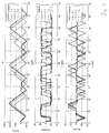
- Fig. 2a shows for four rotary actuators 12 initially the dependence of a rotation angle of the ring gear 10 of the time.
- the units for the rotation angle at the ordinate are arbitrarily enlarged units. It is clear that for the four rotary actuators 12 in the present rotational movement over time, the angular position of the respective teeth of the drive pinion continues to fall apart. It should be noted here that the rotation angles are changed in both directions, and the rotational direction of the rotary actuators 12 is changed to approximately at the times when the rotation angle assumes a maximum or a minimum.
- the changing direction of rotation is also off Fig. 2b clearly where speeds in a first direction of rotation positive and rotational speeds in the opposite direction of rotation are negatively applied.
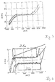
- Fig. 3 shows a characteristic representation in which the torque is plotted against the angle of rotation. Such a representation is possible since both measurement results are parameterized over time. This results in a very clear structure that characterizes the interaction between the rotary drive 12 and the ring gear 10 on a tooth of the drive pinion of the rotary drive 12.
- a first backlash ZS 1 for a first direction of rotation and a second backlash ZS 2 for a second opposite direction of rotation occurs.
- these are essentially the same size, but offset from each other by the angular range.
- Fig. 3 shown is followed by the horizontal region an approximately linearly increasing range.
- the rigidity of the transmission can be determined as ⁇ M / ⁇ phi.
- the stiffness indicates the amount by which the applied torque changes as the angle of rotation changes. The knowledge of the determined values for the rigidity makes it possible to assess any damage and other changes in the gearbox or the rotary drive.
- Fig. 5 shows the exemplary course of a backlash, as measured on a ring gear 10 with four fixed rotary actuators 12.
- the small points 14 denote each here the measured for the specific installation positions of the four rotary actuators 12 backlash games.
- the four Rotary actuators 12 are arranged at 90 ° intervals evenly over the circumference of the ring gear 10. In a region of the toothed rim 10, at an angle of approximately 220 °, the maximum radius r max and the minimum backlash Z fmin are present.
- the predetermined backlash Z f is a non-zero value, which is determined by the geometry of the teeth in the ring gear 10, the geometry of the teeth in the drive pinion and other sizes.
- the backlash In the region of the maximum radius r max the backlash is naturally smallest, ie the teeth of the drive pinion dive deepest in the toothing on the ring gear 10 a.
- the predetermined minimum value for the backlash Z f ensures that the teeth of the drive pinion do not come to the bottom of the teeth of the ring gear 10.
- a rotary drive 12 If a rotary drive 12 is installed and it is not yet known which backlash of the rotary drive 12 should have, it can first be installed in a first position. The slope for the backlash over the azimuth angle can be measured and recorded, either completely or preferably in the range of the maximum radius r max . If this curve was then measured for the current installation position of the rotary drive 12, the rotary drive 12 can be adjusted to a position in which he certainly has a backlash in the range of the maximum radius r max , which is greater than the predetermined backlash Z f .
- the curve indicates which backlash game to be exchanged rotary drive 12 should have at a position of 90 °. It is not necessary to move the range of the maximum radius r max toward the rotary drive 12 in order then to set the predetermined backlash Z f with respect to the minimum backlash Z fmin . Rather, the curve specifies which backlash must be set at an azimuth angle of 90 ° to ensure that even in the range of the maximum radius r max the predetermined backlash Z f is not exceeded.
Landscapes
- Engineering & Computer Science (AREA)
- Mechanical Engineering (AREA)
- Sustainable Development (AREA)
- Sustainable Energy (AREA)
- Chemical & Material Sciences (AREA)
- Combustion & Propulsion (AREA)
- Life Sciences & Earth Sciences (AREA)
- General Engineering & Computer Science (AREA)
- Physics & Mathematics (AREA)
- Fluid Mechanics (AREA)
- Gears, Cams (AREA)
- Wind Motors (AREA)
- Testing Of Devices, Machine Parts, Or Other Structures Thereof (AREA)
- Gear Transmission (AREA)
Description
- Die vorliegende Erfindung betrifft ein Verfahren zur Bestimmung einer Einbauposition für einen Drehantrieb in einer Verstelleinrichtung einer Windenergieanlage. Ein oder mehrere Drehantriebe werden in der Verstelleinrichtung der Windenergieanlage verwendet, um die Rotorblattstellung zu verändern (Pitchsystem) oder um die Gondel entsprechend der Windrichtung auszurichten (Azimutsystem).
- Ein kreisförmiger Zahnkranz einer Verstelleinrichtung besitzt naturgemäß durch seine Herstellung und/oder den Transport eine gewisse Abweichung von der idealen Kreisform. Für einen solchen Zahnkranz einer Verstelleinrichtung ist in der Regel vorgesehen, den Bereich mit dem größten Radius und den Bereich mit dem kleinsten Radius des Zahnkranzes zu markieren. Innerhalb dieses markierten Bereichs erfolgt ein Einstellen eines vorgeschriebenen Zahnflankenspiels nach mechanischen Aspekten, in dem die Drehantrieben in ihrer Lage relativ zum Zahnkranz bestmöglich eingestellt werden.
- Aus
WO 2012/000504 A1 ist ein Positioniersystem mit mehreren Positionierantrieben bekannt geworden, die jeweils einen Sensor für einen Lastparameter aufweisen. Die erfasste Last wird mit erwarteten Lastwerten verglichen, wobei bei einer zu großen Abweichung ein Alarmsignal erzeugt wird. - Aus
US 2014/0064961 A1 ist ein Rotorblattstellantrieb für eine Windenergieanlage bekannt geworden, bei dem zur Speicherung der Null-Position zwei Winkelsensoren eingesetzt werden. - Der Erfindung liegt die Aufgabe zugrunde, ein Verfahren zur Bestimmung einer Einbauposition für einen Drehantrieb in einer Windenergieanlage bereitzustellen, das mit möglichst einfachen Mitteln eine Positionierung des Drehantriebs relativ zu dem Zahnkranz erlaubt.
- Erfindungsgemäß wird die Aufgabe durch ein Verfahren mit den Merkmalen aus Anspruch 1 gelöst. Vorteilhafte Ausgestaltungen bilden die Unteransprüche.
- Das erfindungsgemäße Verfahren dient zur Bestimmung einer Einbauposition für einen Drehantrieb in einer Windenergieanlage. Bei dem Drehantrieb handelt es sich um einen Pitchantrieb oder einen Azimutantrieb, die jeweils aus einem Motor, einem Getriebe und einem Antriebsritzel bestehen. Die Verstelleinrichtung weist einen kreisförmigen Zahnkranz und mindestens einen mit dem Zahnkranz zusammenwirkenden Drehantrieb auf. In dem erfindungsgemäßen Verfahren fährt in einem Verfahrensschritt die Verstelleinrichtung eine Drehposition an. In der angefahrenen Drehposition wird der Zahnkranz der Verstelleinrichtung fixiert, beispielsweise durch ein Festbremsen. In einem nachfolgenden Schritt wird ein Drehmoment in einer Drehrichtung durch den mindestens einen Drehantriebs aufgebracht. Hierzu wird ein Wert für ein zwischen dem Antriebsritzel des Drehantriebs und dem Zahnkranz bestehendes Zahnflankenspiel erfasst. Der erfasste Wert für das Zahnflankenspiel wird in Bezug auf die Drehrichtung, den Drehantriebs und die Drehposition abgespeichert. Dieser Vorgang wird für beide Drehrichtungen, mehrere Drehpositionen und/oder gegebenenfalls weitere Drehantrieben wiederholt. Durch die Wiederholung entsteht eine mehr oder weniger vollständige Darstellung des Zahnflankenspiels für einen oder mehrere Drehantriebe in einer oder mehreren Drehpositionen der Verstelleinrichtung. Ausgehend von diesen gespeicherten Werten kann für einen Drehantrieb eine Einbauposition gefunden werden, bei der ein minimales Zahnflankenspiel einem vorbestimmten Zahnflankenspiel entspricht.
- Das vorbestimmte Zahnflankenspiel ist konstruktiv beispielsweise durch die Form der Zähne und das Verhältnis der Durchmesser von Antriebsritzel und Zahnkranz vorgegeben. Es wird also eine Einbauposition gesucht und eingestellt, bei der das minimale Zahnflankenspiel bei einer vollständigen Drehung des Zahnkranzes stets gleich dem oder größer als das vorbestimmte Zahnflankenspiel ist. Der Vorteil des erfindungsgemäßen Verfahrens liegt ganz wesentlich darin, dass keine Verdrehbewegung der Verstelleinrichtung zum Auffinden der richtigen Einbauposition, beispielsweise bei einem Tausch des Drehantriebs, erfolgen muss. Vielmehr kann aufgrund des abgespeicherten Zahnflankenspiels eine korrekte Einbauposition im Vorfelde für eine beliebige Drehposition der Verstelleinrichtung bestimmt werden.
- In einer bevorzugten Ausgestaltung wird beim Erfassen des Zahnflankenspiels die Drehrichtung des Drehantriebs gewechselt, sodass die Werte des Zahnflankenspiels für beide Drehrichtungen vorliegen.
- In einer weiteren bevorzugten Ausgestaltung werden beim Erfassen des Zahnflankenspiels ein Drehwinkel und/oder eine Drehzahl zusammen mit einem Drehmoment des Drehantriebs ausgewertet. Dies schafft die Möglichkeit, den Drehwinkel und/oder die Drehzahl abhängig von einem erfassten Drehmoment auszuwerten. Das Zahnflankenspiel kann hierbei als der Winkelbereich angesehen werden, in dem der Drehantrieb mit einem konstanten Drehmoment verfahren wird. Ist der Winkelbereich des Zahnflankenspiels durchfahren, steigt das Drehmoment an.
- In einer bevorzugten Ausgestaltung des erfindungsgemäßen Verfahrens ist die Einbauposition des Drehantriebs in einer Drehantriebshalterung relativ zu dem Zahnkranz einstellbar. Durch die Einstellbarkeit wird erreicht, dass ein neuer Drehantrieb beispielsweise in seine Drehantriebshalterung eingesetzt und dort für das gewünschte Zahnflankenspiel eingestellt werden kann. Ein solches Drehwerk ist beispielsweise aus
EP 2 960 490 A1 bekannt. - In einer bevorzugten Weiterbildung des erfindungsgemäßen Verfahrens ist an der Verstelleinrichtung ein Getriebeflansch vorgesehen. Der Getriebeflansch weist eine Bohrung auf, die als Drehantriebshalterung ausgebildet ist. Für den in der Bohrung angeordneten Drehantrieb ist das Antriebsritzel exzentrisch zu dem Getriebeflansch ausgerichtet. Durch die exzentrische Anordnung kann der Drehantrieb durch eine Drehung in der Bohrung der Drehantriebshalterung in seine gewünschte Einbauposition gedreht werden.
- Ein weiterer Vorzug des erfindungsgemäßen Verfahrens besteht darin, dass auch eine Steifigkeit eines Getriebes an dem Drehantrieb ermittelt werden kann. Hierzu wird eine Änderung des Drehmoments in Abhängigkeit von einer Änderung des Drehwinkels des Antriebsritzels ausgewertet. Diese Daten zur Steifigkeit des Getriebes können beispielsweise bei der Überwachung des Zustandes der Verstelleinrichtung berücksichtigt werden. Die Steifigkeit des Getriebes gibt Aufschluss über etwaige Abnutzungen oder Beschädigungen im Getriebe.
- Wenn das Zahnflankenspiel nicht vollständig für den gesamten Umfang erfasst wird, kann das minimale Zahnflankenspiel auch im Bereich des maximalen Radius des Zahnkranzes ermittelt werden.
- Die Erfindung wird nachfolgend näher erläutert. Es zeigen:
- Fig. 1
- eine schematische Darstellung einer Verstelleinrichtung mit vier Drehantrieben,
- Fig. 2
- die bei einem Messvorgang erfassten Werte für Drehwinkel, Drehzahl und Drehmoment, abhängig von der Zeit,
- Fig. 3
- eine Darstellung des Zahnflankenspiels mit einem Drehmoment, abhängig von einer Winkelposition,
- Fig. 4
- eine Darstellung des Winkelbereichs des Zahnflankenspiels in einer Detailansicht aus
Fig. 3 und - Fig. 5
- Verlauf des Zahnflankenspiels abhängig vom Azimutwinkel.
-
Fig. 1 zeigt in einer schematischen Darstellung einen Zahnkranz 10 mit vier über dessen Umfang verteilten Drehantrieben 12. Jeder der Drehantrieben 12 besitzt ein in dem Zahnkranz 10 kämmendes Antriebsritzel, das von einem Motor und einem Getriebe (nicht dargestellt) angetrieben wird. Der Motor kann beispielsweise ein Elektromotor sein, der von einem Frequenzumrichter angesteuert wird. Hydraulikmotoren sind ebenfalls möglich. Je nach Ausgestaltung und Einbauposition des Zahnkranzes 10 in der Windenergieanlage, kann dessen Zahnung auf der Innenseite oder der Außenseite des Zahnkranzes 10 angeordnet sein. Durch eine Ansteuerung der Drehantriebe 12 kann der Zahnkranz 10 beispielsweise in Drehrichtung 14 gedreht werden, so dass die Arbeitspositionen AP1, AP2 und AP3 angefahren werden. Die Arbeitsposition APX dient als Referenz, von der aus ein Drehwinkel gezählt wird. - Bei dem erfindungsgemäßen Verfahren wird eine Arbeitsposition angefahren und der Zahnkranz 10 in dieser Arbeitsposition fixiert, beispielsweise durch Bremskaliber einer Bremsvorrichtung festgebremst. Handelt es sich bei der Verstelleinrichtung um eine Azimutdrehverbindung, so wird die Azimutposition in Bezug zur Windrichtung häufig durch vorhandene Hydraulikbremsen gehalten, wenn keine Verstellbewegung der Azimutdrehverbindung erfolgt. Durch abwechselndes Anlegen eines begrenzten Drehmoments an beide Zahnflanken eines einzelnen Zahns des Antriebsritzels des Drehantriebs 12 und gleichzeitige Erfassung der dabei auftretenden Drehmomente und Drehzahlen kann das Zahnflankenspiel des jeweiligen Drehantriebs 12 aus den erfassten Werten berechnet werden. Dieses Zahnflankenspiel wird in mehreren Arbeitspositionen bestimmt, abgespeichert und kann mit Bezug auf die Arbeitspositionen wieder aufgerufen werden. Anhand dieser Daten lässt sich ein minimales Zahnflankenspiel für den gesamten Zahnkranz 10 bestimmen. Gleichzeitig kann für jede Arbeitsposition des Zahnkranzes 10 bei einem Tausch des Drehantriebs 12 das entsprechende Zahnflankenspiel vorgegeben werden.
-
Fig. 2a zeigt für vier Drehantrieben 12 zunächst die Abhängigkeit eines Drehwinkels des Zahnkranzes 10 von der Zeit. Die Einheiten für den Drehwinkel an der Ordinate sind beliebig vergrößerte Einheiten. Deutlich wird, dass für die vier Drehantrieben 12 bei der vorliegenden Drehbewegung mit der Zeit die Winkellage der jeweiligen Zähne der Antriebsritzel immer weiter auseinanderfällt. Hierbei ist zu beachten, dass die Drehwinkel in beiden Richtungen verändert werden, wobei die Drehrichtung der Drehantriebe 12 ungefähr zu den Zeitpunkten, wo der Drehwinkel ein Maximum oder ein Minimum annimmt, geändert wird. Die sich ändernde Drehrichtung wird auch ausFig. 2b deutlich, wo Drehzahlen in eine erste Drehrichtung positiv und Drehzahlen in entgegengesetzter Drehrichtung negativ aufgetragen sind. Auch in der Darstellung der Drehzahlen wiederholt sich die bereits für die Drehwinkel festgestellte, typische Struktur, dass mit der Zeit beim Verfahren der Verstelleinrichtung die Werte für das Zahnflankenspiel zeitlich mehr und mehr auseinanderfallen. Eine ähnliche Struktur ergibt sich auch für das ausgeübte Drehmoment inFig. 2c . Auch hier erfolgt der Richtungswechsel der Drehantriebe 12 in den Zeitpunkten des maximalen oder minimalen Drehmoments. -
Fig. 3 zeigt eine charakteristische Darstellung, bei der das Drehmoment über dem Drehwinkel aufgetragen ist. Eine solche Darstellung ist möglich, da beide Messergebnisse über die Zeit parametrisiert sind. Es ergibt sich hieraus eine sehr deutliche Struktur, die das Zusammenspiel zwischen dem Drehantrieb 12 und dem Zahnkranz 10 an einem Zahn des Antriebsritzels des Drehantriebs 12 kennzeichnet. - Wie in
Fig. 4 dargestellt, gibt es einen Winkelbereich, in dem sich bei der Änderung des Drehwinkels das Drehmoment im Wesentlichen nicht ändert. - Wie in
Fig. 4 eingezeichnet, gibt es im Wesentlichen zwei Zahnflankenspiele, wobei ein erstes Zahnflankenspiel ZS1 für eine erste Drehrichtung und ein zweites Zahnflankenspiel ZS2 für eine zweite entgegengesetzte Drehrichtung auftritt. Wie inFig. 4 dargestellt, sind diese im Wesentlichen gleich groß, allerdings vom Winkelbereich versetzt zueinander. Wie inFig. 3 dargestellt, schließt sich an den horizontalen Bereich ein ungefähr linear steigender Bereich an. In dem linear steigenden Bereich kann die Steifigkeit des Getriebes als ΔM/Δphi ermittelt werden. Die Steifigkeit gibt an, um welchen Betrag sich das anliegende Drehmoment bei einer Änderung des Drehwinkels verändert. Die Kenntnis der ermittelten Werte für die Steifigkeit erlaubt es, etwaige Beschädigungen und andere Veränderungen in dem Getriebe oder dem Drehantrieb beurteilen zu können. -
Fig. 5 zeigt den beispielhaften Verlauf eines Zahnflankenspiels, wie es an einem Zahnkranz 10 mit vier fest eingebauten Drehantrieben 12 gemessen wurde. Die klein dargestellten Punkte 14 bezeichnen hier jeweils die für die konkreten Einbaupositionen der vier Drehantrieben 12 gemessenen Zahnflankenspiele. Die vier Drehantriebe 12 sind in 90°-Abständen gleichmäßig über den Umfang des Zahnkranzes 10 angeordnet. In einem Bereich des Zahnkranzes 10, bei einem Winkel von ungefähr 220°, liegen der maximale Radius rmax und das minimale Zahnflankenspiel Zfminvor. Das vorbestimmte Zahnflankenspiel Zf ist hingegen ein von null verschiedener Wert, der durch die Geometrie der Zähne im Zahnkranz 10, die Geometrie der Zähne im Antriebsritzel und weitere Größen vorgegeben ist. Im Bereich des maximalen Radius rmax ist das Zahnflankenspiel naturgemäß am kleinsten, d. h. die Zähne des Antriebsritzels tauchen am tiefsten in die Zahnung am Zahnkranz 10 ein. Durch den vorbestimmten minimalen Wert für das Zahnflankenspiel Zf wird sichergestellt, dass die Zähne des Antriebsritzels nicht auf den Grund der Zahnung des Zahnkranzes 10 kommen. Im Bereich des minimalen Radius rmin liegt ein maximales Zahnflankenspiel vor. Hier muss sichergestellt sein, dass noch eine ausreichende Kraftübertragung zwischen Antriebsritzel und Zahnkranz erfolgt. In der Regel gibt es auch einen vorbestimmten Wert für das maximale Zahnflankenspiel, der nicht überschritten werden darf. - Die in
Fig. 5 dargestellte Kurve hat nun zweierlei Bedeutung. Wird ein Drehantriebs 12 eingebaut und ist noch nicht bekannt, welches Zahnflankenspiel der Drehantriebs 12 besitzen soll, so kann dieser zunächst in einer ersten Position eingebaut werden. Die Kurve für das Zahnflankenspiel über dem Azimutwinkel kann gemessen und aufgezeichnet werden, entweder vollständig oder bevorzugt im Bereich des maximalen Radius rmax. Ist diese Kurve dann für die aktuelle Einbauposition des Drehantriebs 12 gemessen worden, kann der Drehantrieb 12 in eine Position verstellt werden, in der er sicher auch im Bereich des maximalen Radius rmax ein Zahnflankenspiel besitzt, das größer als das vorbestimmte Zahnflankenspiel Zf ist. - Ist die Kurve bereits einmal aufgenommen worden und soll nun ein Drehantrieb 12, beispielsweise der Drehantrieb 12, der in einer Position bei nahe 90° eingebaut ist, ausgetauscht werden, so gibt die Kurve an, welches Zahnflankenspiel der auszutauschende Drehantrieb 12 bei einer Stellung von 90° besitzen soll. Es ist nicht notwendig, den Bereich des maximalen Radius rmax zu dem Drehantrieb 12 hin zu verfahren, um dann dort das vorbestimmte Zahnflankenspiel Zf in Bezug zum minimalen Zahnflankenspiel Zfmin einzustellen. Vielmehr gibt die Kurve vor, welches Zahnflankenspiel bei einem Azimutwinkel von 90° eingestellt werden muss, um sicherzustellen, dass auch im Bereich des maximalen Radius rmax das vorbestimmte Zahnflankenspiel Zf nicht unterschritten wird.
-
- 10
- Zahnkranz
- 12
- Drehantrieb
- 14
- Drehrichtung
- Zf
- vorbestimmtes Zahnflankenspiel
- Zfmin
- minimales Zahnflankenspiel
- rmax
- maximaler Radius
- rmin
- minimaler Radius
- ZS
- Zahnflankenspiel
- ZS1
- erstes Zahnflankenspiel
- ZS2
- zweites Zahnflankenspiel
- AP1
- erste Arbeitsposition
- AP2
- zweite Arbeitsposition
- AP3
- dritte Arbeitsposition
- APX
- Referenzpunkt
Claims (8)
- Verfahren zur Bestimmung einer Einbauposition für einen Drehantrieb (12) in einer Windenergieanlage, die eine Verstelleinrichtung mit einem Zahnkranz (10) und mit mindestens einem mit dem Zahnkranz (10) zusammenwirkenden Drehantrieb (12) aufweist, das folgende Schritte durchführt:- Anfahren einer Drehposition des Zahnkranzes (10) mit mindestens einem der Drehantrieben (12) der Verstelleinrichtung,- Fixieren des Zahnkranzes (10) in der angefahrenen Drehposition,- Aufbringen eines Drehmoments an dem Zahnkranz (10) in einer ersten Drehrichtung mit einem Drehantrieb (12),- Erfassen eines Wertes für ein Zahnflankenspiel ZS für einen Zahn eines Antriebsritzels des Drehantriebs (12) und Abspeichern des erfassten Werts für das Zahnflankenspiel ZS für die Drehrichtung, den Drehantrieb (12) und die Drehposition,- Wiederholen des Vorgangs für mehrere Drehpositionen und/oder weitere Drehantrieben (12),- Ermitteln eines minimalen Zahnflankenspiels Zfmin aus den erfassten Werten für das Zahnflankenspiel,- Festlegen einer Einbauposition für den Drehantrieb (12), in der das minimale Zahnflankenspiel Zfmin größer oder gleich einem vorbestimmten Zahnflankenspiel Zf ist.
- Verfahren nach Anspruch 1, dadurch gekennzeichnet, dass das Zahnflankenspiel ZS für eine zweite, entgegengesetzte Drehrichtung erfasst wird.
- Verfahren nach Anspruch 1 oder 2, dadurch gekennzeichnet, dass beim Erfassen des Zahnflankenspiels ZS ein Drehwinkel und/oder eine Drehzahl zusammen mit einem Drehmoment des Drehantriebs (12) erfasst und ausgewertet werden.
- Verfahren nach Anspruch 3, dadurch gekennzeichnet, dass ein Winkelbereich mit einem konstanten Drehmoment als Zahnflankenspiel ZS erfasst wird.
- Verfahren nach einem der Ansprüche 1 bis 4, dadurch gekennzeichnet, dass die Einbauposition des Drehantriebs (12) in einer Drehantriebshalterung relativ zu dem Zahnkranz (10) einstellbar ist.
- Verfahren nach Anspruch 5, dadurch gekennzeichnet, dass ein Getriebeflansch an dem Drehantrieb (12) vorgesehen ist, wobei das Antriebsritzel exzentrisch zu dem Getriebeflansch angeordnet ist.
- Verfahren nach einem der Ansprüche 1 bis 6, dadurch gekennzeichnet, dass der Drehantrieb (12) ein Getriebe aufweist und eine Steifigkeit des Getriebes ermittelt wird, wobei hierzu eine Änderung des Drehmoments in Abhängigkeit von einer Änderung des Drehwinkels ausgewertet wird.
- Verfahren nach einem der Ansprüche 1 bis 7, dadurch gekennzeichnet, dass das Zahnflankenspiel ZS in einem Drehwinkelbereich erfasst wird, in dem der Zahnkranz (10) seinen maximalen Radius rmax besitzt.
Priority Applications (3)
| Application Number | Priority Date | Filing Date | Title |
|---|---|---|---|
| EP16180377.0A EP3273054B1 (de) | 2016-07-20 | 2016-07-20 | Verfahren zur bestimmung einer einbauposition für einen drehantrieb in einer windenergieanlage |
| ES16180377T ES2731464T3 (es) | 2016-07-20 | 2016-07-20 | Procedimiento para determinar una posición de instalación para un accionamiento giratorio en un aerogenerador |
| DK16180377.0T DK3273054T3 (da) | 2016-07-20 | 2016-07-20 | Fremgangsmåde til bestemmelse af en monteringsposition for et drejedrev i et vindenergianlæg |
Applications Claiming Priority (1)
| Application Number | Priority Date | Filing Date | Title |
|---|---|---|---|
| EP16180377.0A EP3273054B1 (de) | 2016-07-20 | 2016-07-20 | Verfahren zur bestimmung einer einbauposition für einen drehantrieb in einer windenergieanlage |
Publications (2)
| Publication Number | Publication Date |
|---|---|
| EP3273054A1 true EP3273054A1 (de) | 2018-01-24 |
| EP3273054B1 EP3273054B1 (de) | 2019-03-27 |
Family
ID=56555202
Family Applications (1)
| Application Number | Title | Priority Date | Filing Date |
|---|---|---|---|
| EP16180377.0A Active EP3273054B1 (de) | 2016-07-20 | 2016-07-20 | Verfahren zur bestimmung einer einbauposition für einen drehantrieb in einer windenergieanlage |
Country Status (3)
| Country | Link |
|---|---|
| EP (1) | EP3273054B1 (de) |
| DK (1) | DK3273054T3 (de) |
| ES (1) | ES2731464T3 (de) |
Cited By (2)
| Publication number | Priority date | Publication date | Assignee | Title |
|---|---|---|---|---|
| CN115263667A (zh) * | 2021-04-30 | 2022-11-01 | 纳博特斯克有限公司 | 风车的驱动机构的调整方法和驱动机构的调整方法 |
| CN116292148A (zh) * | 2023-04-28 | 2023-06-23 | 上海致远绿色能源股份有限公司 | 中型风力发电机组变桨传动系统健康度诊断方法 |
Citations (5)
| Publication number | Priority date | Publication date | Assignee | Title |
|---|---|---|---|---|
| CN201401278Y (zh) * | 2009-04-23 | 2010-02-10 | 锋电能源技术有限公司 | 一种齿隙可调的风力发电机组变桨系统及其齿隙调整装置 |
| US20110138945A1 (en) * | 2010-05-31 | 2011-06-16 | Mitsubishi Heavy Industries, Ltd. | Wind turbine generator, and method of controlling the sind turbine generator |
| WO2012000504A1 (en) | 2010-06-29 | 2012-01-05 | Vestas Wind Systems A/S | Rotational positioning system in a wind turbine |
| US20140064961A1 (en) | 2012-09-06 | 2014-03-06 | Delta Electronics, Inc. | Method for backing up and recovering blade zero point of pitch drive system for wind turbine and pitch drive system for wind turbine |
| EP2960490A1 (de) | 2014-06-26 | 2015-12-30 | Senvion GmbH | Drehwerk zur verdrehung eines drehbar an einer windenergieanlage gelagerten bauteils |
-
2016
- 2016-07-20 DK DK16180377.0T patent/DK3273054T3/da active
- 2016-07-20 EP EP16180377.0A patent/EP3273054B1/de active Active
- 2016-07-20 ES ES16180377T patent/ES2731464T3/es active Active
Patent Citations (5)
| Publication number | Priority date | Publication date | Assignee | Title |
|---|---|---|---|---|
| CN201401278Y (zh) * | 2009-04-23 | 2010-02-10 | 锋电能源技术有限公司 | 一种齿隙可调的风力发电机组变桨系统及其齿隙调整装置 |
| US20110138945A1 (en) * | 2010-05-31 | 2011-06-16 | Mitsubishi Heavy Industries, Ltd. | Wind turbine generator, and method of controlling the sind turbine generator |
| WO2012000504A1 (en) | 2010-06-29 | 2012-01-05 | Vestas Wind Systems A/S | Rotational positioning system in a wind turbine |
| US20140064961A1 (en) | 2012-09-06 | 2014-03-06 | Delta Electronics, Inc. | Method for backing up and recovering blade zero point of pitch drive system for wind turbine and pitch drive system for wind turbine |
| EP2960490A1 (de) | 2014-06-26 | 2015-12-30 | Senvion GmbH | Drehwerk zur verdrehung eines drehbar an einer windenergieanlage gelagerten bauteils |
Cited By (2)
| Publication number | Priority date | Publication date | Assignee | Title |
|---|---|---|---|---|
| CN115263667A (zh) * | 2021-04-30 | 2022-11-01 | 纳博特斯克有限公司 | 风车的驱动机构的调整方法和驱动机构的调整方法 |
| CN116292148A (zh) * | 2023-04-28 | 2023-06-23 | 上海致远绿色能源股份有限公司 | 中型风力发电机组变桨传动系统健康度诊断方法 |
Also Published As
| Publication number | Publication date |
|---|---|
| ES2731464T3 (es) | 2019-11-15 |
| EP3273054B1 (de) | 2019-03-27 |
| DK3273054T3 (da) | 2019-07-08 |
Similar Documents
| Publication | Publication Date | Title |
|---|---|---|
| EP1794449B1 (de) | Verfahren zum betreiben einer vorrichtung zum verstellen eines blatteinstellwinkels sowie eine verstellvorrichtung | |
| EP2014915B1 (de) | Drehzahlbestimmung | |
| DE19739164B4 (de) | Windenergieanlage | |
| DE19739162A1 (de) | Windenergieanlage | |
| EP1847498A1 (de) | Verfahren und Vorrichtung zum Verlegen von langgestrecktem Wickelgut | |
| DE102016209507B4 (de) | Charakterisierung eines Haftreibungszustandes in einem elektrisch unterstützten Lenksystem | |
| DE102008021849A1 (de) | Elektromechanisches Lenksystem mit Anpassung des Lenkwinkels der Räder an den Handwinkel | |
| EP2536530B1 (de) | Verfahren zum betrieb eines schwenkantriebs | |
| EP2226463A2 (de) | Torantrieb mit zwei Motoren | |
| EP3472459B1 (de) | Verfahren zur überwachung einer rotorblattverstellung | |
| EP2607856A2 (de) | Vorrichtung zur Messung von Drehmoment, Drehrichtung und Drehgeschwindigkeit einer Welle eines Getriebes, insbesondere einer Antriebswelle eines Azimutgetriebes einer Windkraftanlage | |
| WO2019197680A1 (de) | Windenergieanlage, windpark sowie verfahren zum regeln einer windenergieanlage und eines windparks | |
| DE102014110413A1 (de) | Gelenkverbindung für einen Roboter | |
| DE10244407A1 (de) | Elektrische Fahrzeugparkbremsvorrichtung | |
| WO2013072005A1 (de) | Verfahren zur dämpfung von torsionsschwingungen in einer energieerzeugungsanlage | |
| EP2796710B1 (de) | Verfahren und Steuerungsvorrichtung zum Verspannen einer Windnachführungsanordnung einer Windenergieanlage | |
| DE102012110466A1 (de) | Verfahren zum Betreiben einer Windenergieanlage, Windenergieanlage und Steuerungseinrichtung für eine Windenergieanlage | |
| EP3273054B1 (de) | Verfahren zur bestimmung einer einbauposition für einen drehantrieb in einer windenergieanlage | |
| EP1524433B1 (de) | Drehzahlregelung in einer Windenergieanlage mit zwei Näherungssensoren für die Drehzahlmessung | |
| EP3104503A1 (de) | Spielfreier drehantrieb | |
| DE102013006281A1 (de) | Antriebs- oder Verstellvorrichtung | |
| DE102015006040B4 (de) | Rotor-Arretierungseinrichtung mit einem formschlüssigen Haltemoment | |
| DE102022130859A1 (de) | Verfahren zum Betrieb eines Antriebssystems zur Vermeidung von Eingriffsstörungen in Spannungswellengetrieben | |
| EP3322641A1 (de) | Steuerstange zum verstellen von einem rotorblatt eines hubschraubers | |
| AT527841B1 (de) | Koaxialgetriebe mit integrierter messsensorik |
Legal Events
| Date | Code | Title | Description |
|---|---|---|---|
| PUAI | Public reference made under article 153(3) epc to a published international application that has entered the european phase |
Free format text: ORIGINAL CODE: 0009012 |
|
| STAA | Information on the status of an ep patent application or granted ep patent |
Free format text: STATUS: THE APPLICATION HAS BEEN PUBLISHED |
|
| AK | Designated contracting states |
Kind code of ref document: A1 Designated state(s): AL AT BE BG CH CY CZ DE DK EE ES FI FR GB GR HR HU IE IS IT LI LT LU LV MC MK MT NL NO PL PT RO RS SE SI SK SM TR |
|
| AX | Request for extension of the european patent |
Extension state: BA ME |
|
| STAA | Information on the status of an ep patent application or granted ep patent |
Free format text: STATUS: REQUEST FOR EXAMINATION WAS MADE |
|
| 17P | Request for examination filed |
Effective date: 20180605 |
|
| RBV | Designated contracting states (corrected) |
Designated state(s): AL AT BE BG CH CY CZ DE DK EE ES FI FR GB GR HR HU IE IS IT LI LT LU LV MC MK MT NL NO PL PT RO RS SE SI SK SM TR |
|
| GRAP | Despatch of communication of intention to grant a patent |
Free format text: ORIGINAL CODE: EPIDOSNIGR1 |
|
| STAA | Information on the status of an ep patent application or granted ep patent |
Free format text: STATUS: GRANT OF PATENT IS INTENDED |
|
| RIC1 | Information provided on ipc code assigned before grant |
Ipc: F03D 7/02 20060101AFI20181003BHEP Ipc: F03D 13/30 20160101ALI20181003BHEP |
|
| INTG | Intention to grant announced |
Effective date: 20181023 |
|
| GRAS | Grant fee paid |
Free format text: ORIGINAL CODE: EPIDOSNIGR3 |
|
| GRAA | (expected) grant |
Free format text: ORIGINAL CODE: 0009210 |
|
| STAA | Information on the status of an ep patent application or granted ep patent |
Free format text: STATUS: THE PATENT HAS BEEN GRANTED |
|
| AK | Designated contracting states |
Kind code of ref document: B1 Designated state(s): AL AT BE BG CH CY CZ DE DK EE ES FI FR GB GR HR HU IE IS IT LI LT LU LV MC MK MT NL NO PL PT RO RS SE SI SK SM TR |
|
| REG | Reference to a national code |
Ref country code: GB Ref legal event code: FG4D Free format text: NOT ENGLISH |
|
| REG | Reference to a national code |
Ref country code: CH Ref legal event code: EP |
|
| REG | Reference to a national code |
Ref country code: DE Ref legal event code: R096 Ref document number: 502016003885 Country of ref document: DE |
|
| REG | Reference to a national code |
Ref country code: AT Ref legal event code: REF Ref document number: 1113399 Country of ref document: AT Kind code of ref document: T Effective date: 20190415 |
|
| REG | Reference to a national code |
Ref country code: IE Ref legal event code: FG4D Free format text: LANGUAGE OF EP DOCUMENT: GERMAN |
|
| REG | Reference to a national code |
Ref country code: DK Ref legal event code: T3 Effective date: 20190704 |
|
| PG25 | Lapsed in a contracting state [announced via postgrant information from national office to epo] |
Ref country code: NO Free format text: LAPSE BECAUSE OF FAILURE TO SUBMIT A TRANSLATION OF THE DESCRIPTION OR TO PAY THE FEE WITHIN THE PRESCRIBED TIME-LIMIT Effective date: 20190627 Ref country code: FI Free format text: LAPSE BECAUSE OF FAILURE TO SUBMIT A TRANSLATION OF THE DESCRIPTION OR TO PAY THE FEE WITHIN THE PRESCRIBED TIME-LIMIT Effective date: 20190327 Ref country code: LT Free format text: LAPSE BECAUSE OF FAILURE TO SUBMIT A TRANSLATION OF THE DESCRIPTION OR TO PAY THE FEE WITHIN THE PRESCRIBED TIME-LIMIT Effective date: 20190327 Ref country code: SE Free format text: LAPSE BECAUSE OF FAILURE TO SUBMIT A TRANSLATION OF THE DESCRIPTION OR TO PAY THE FEE WITHIN THE PRESCRIBED TIME-LIMIT Effective date: 20190327 |
|
| REG | Reference to a national code |
Ref country code: NL Ref legal event code: MP Effective date: 20190327 |
|
| PG25 | Lapsed in a contracting state [announced via postgrant information from national office to epo] |
Ref country code: NL Free format text: LAPSE BECAUSE OF FAILURE TO SUBMIT A TRANSLATION OF THE DESCRIPTION OR TO PAY THE FEE WITHIN THE PRESCRIBED TIME-LIMIT Effective date: 20190327 Ref country code: LV Free format text: LAPSE BECAUSE OF FAILURE TO SUBMIT A TRANSLATION OF THE DESCRIPTION OR TO PAY THE FEE WITHIN THE PRESCRIBED TIME-LIMIT Effective date: 20190327 Ref country code: RS Free format text: LAPSE BECAUSE OF FAILURE TO SUBMIT A TRANSLATION OF THE DESCRIPTION OR TO PAY THE FEE WITHIN THE PRESCRIBED TIME-LIMIT Effective date: 20190327 Ref country code: BG Free format text: LAPSE BECAUSE OF FAILURE TO SUBMIT A TRANSLATION OF THE DESCRIPTION OR TO PAY THE FEE WITHIN THE PRESCRIBED TIME-LIMIT Effective date: 20190627 Ref country code: GR Free format text: LAPSE BECAUSE OF FAILURE TO SUBMIT A TRANSLATION OF THE DESCRIPTION OR TO PAY THE FEE WITHIN THE PRESCRIBED TIME-LIMIT Effective date: 20190628 Ref country code: HR Free format text: LAPSE BECAUSE OF FAILURE TO SUBMIT A TRANSLATION OF THE DESCRIPTION OR TO PAY THE FEE WITHIN THE PRESCRIBED TIME-LIMIT Effective date: 20190327 |
|
| PG25 | Lapsed in a contracting state [announced via postgrant information from national office to epo] |
Ref country code: AL Free format text: LAPSE BECAUSE OF FAILURE TO SUBMIT A TRANSLATION OF THE DESCRIPTION OR TO PAY THE FEE WITHIN THE PRESCRIBED TIME-LIMIT Effective date: 20190327 Ref country code: SK Free format text: LAPSE BECAUSE OF FAILURE TO SUBMIT A TRANSLATION OF THE DESCRIPTION OR TO PAY THE FEE WITHIN THE PRESCRIBED TIME-LIMIT Effective date: 20190327 Ref country code: PT Free format text: LAPSE BECAUSE OF FAILURE TO SUBMIT A TRANSLATION OF THE DESCRIPTION OR TO PAY THE FEE WITHIN THE PRESCRIBED TIME-LIMIT Effective date: 20190727 Ref country code: RO Free format text: LAPSE BECAUSE OF FAILURE TO SUBMIT A TRANSLATION OF THE DESCRIPTION OR TO PAY THE FEE WITHIN THE PRESCRIBED TIME-LIMIT Effective date: 20190327 Ref country code: IT Free format text: LAPSE BECAUSE OF FAILURE TO SUBMIT A TRANSLATION OF THE DESCRIPTION OR TO PAY THE FEE WITHIN THE PRESCRIBED TIME-LIMIT Effective date: 20190327 Ref country code: CZ Free format text: LAPSE BECAUSE OF FAILURE TO SUBMIT A TRANSLATION OF THE DESCRIPTION OR TO PAY THE FEE WITHIN THE PRESCRIBED TIME-LIMIT Effective date: 20190327 Ref country code: EE Free format text: LAPSE BECAUSE OF FAILURE TO SUBMIT A TRANSLATION OF THE DESCRIPTION OR TO PAY THE FEE WITHIN THE PRESCRIBED TIME-LIMIT Effective date: 20190327 |
|
| PG25 | Lapsed in a contracting state [announced via postgrant information from national office to epo] |
Ref country code: SM Free format text: LAPSE BECAUSE OF FAILURE TO SUBMIT A TRANSLATION OF THE DESCRIPTION OR TO PAY THE FEE WITHIN THE PRESCRIBED TIME-LIMIT Effective date: 20190327 Ref country code: PL Free format text: LAPSE BECAUSE OF FAILURE TO SUBMIT A TRANSLATION OF THE DESCRIPTION OR TO PAY THE FEE WITHIN THE PRESCRIBED TIME-LIMIT Effective date: 20190327 |
|
| PG25 | Lapsed in a contracting state [announced via postgrant information from national office to epo] |
Ref country code: IS Free format text: LAPSE BECAUSE OF FAILURE TO SUBMIT A TRANSLATION OF THE DESCRIPTION OR TO PAY THE FEE WITHIN THE PRESCRIBED TIME-LIMIT Effective date: 20190727 |
|
| REG | Reference to a national code |
Ref country code: DE Ref legal event code: R097 Ref document number: 502016003885 Country of ref document: DE |
|
| PLBE | No opposition filed within time limit |
Free format text: ORIGINAL CODE: 0009261 |
|
| STAA | Information on the status of an ep patent application or granted ep patent |
Free format text: STATUS: NO OPPOSITION FILED WITHIN TIME LIMIT |
|
| PG25 | Lapsed in a contracting state [announced via postgrant information from national office to epo] |
Ref country code: MC Free format text: LAPSE BECAUSE OF FAILURE TO SUBMIT A TRANSLATION OF THE DESCRIPTION OR TO PAY THE FEE WITHIN THE PRESCRIBED TIME-LIMIT Effective date: 20190327 Ref country code: SI Free format text: LAPSE BECAUSE OF FAILURE TO SUBMIT A TRANSLATION OF THE DESCRIPTION OR TO PAY THE FEE WITHIN THE PRESCRIBED TIME-LIMIT Effective date: 20190327 |
|
| REG | Reference to a national code |
Ref country code: CH Ref legal event code: PL |
|
| 26N | No opposition filed |
Effective date: 20200103 |
|
| PG25 | Lapsed in a contracting state [announced via postgrant information from national office to epo] |
Ref country code: TR Free format text: LAPSE BECAUSE OF FAILURE TO SUBMIT A TRANSLATION OF THE DESCRIPTION OR TO PAY THE FEE WITHIN THE PRESCRIBED TIME-LIMIT Effective date: 20190327 |
|
| REG | Reference to a national code |
Ref country code: BE Ref legal event code: MM Effective date: 20190731 |
|
| PG25 | Lapsed in a contracting state [announced via postgrant information from national office to epo] |
Ref country code: LI Free format text: LAPSE BECAUSE OF NON-PAYMENT OF DUE FEES Effective date: 20190731 Ref country code: CH Free format text: LAPSE BECAUSE OF NON-PAYMENT OF DUE FEES Effective date: 20190731 Ref country code: BE Free format text: LAPSE BECAUSE OF NON-PAYMENT OF DUE FEES Effective date: 20190731 Ref country code: LU Free format text: LAPSE BECAUSE OF NON-PAYMENT OF DUE FEES Effective date: 20190720 |
|
| PG25 | Lapsed in a contracting state [announced via postgrant information from national office to epo] |
Ref country code: FR Free format text: LAPSE BECAUSE OF NON-PAYMENT OF DUE FEES Effective date: 20190731 |
|
| PG25 | Lapsed in a contracting state [announced via postgrant information from national office to epo] |
Ref country code: IE Free format text: LAPSE BECAUSE OF NON-PAYMENT OF DUE FEES Effective date: 20190720 |
|
| REG | Reference to a national code |
Ref country code: DE Ref legal event code: R082 Ref document number: 502016003885 Country of ref document: DE Representative=s name: HAUCK PATENTANWALTSPARTNERSCHAFT MBB, DE Ref country code: DE Ref legal event code: R081 Ref document number: 502016003885 Country of ref document: DE Owner name: NORDEX ENERGY SE & CO. KG, DE Free format text: FORMER OWNER: NORDEX ENERGY GMBH, 22419 HAMBURG, DE |
|
| GBPC | Gb: european patent ceased through non-payment of renewal fee |
Effective date: 20200720 |
|
| PG25 | Lapsed in a contracting state [announced via postgrant information from national office to epo] |
Ref country code: GB Free format text: LAPSE BECAUSE OF NON-PAYMENT OF DUE FEES Effective date: 20200720 |
|
| PG25 | Lapsed in a contracting state [announced via postgrant information from national office to epo] |
Ref country code: CY Free format text: LAPSE BECAUSE OF FAILURE TO SUBMIT A TRANSLATION OF THE DESCRIPTION OR TO PAY THE FEE WITHIN THE PRESCRIBED TIME-LIMIT Effective date: 20190327 |
|
| PG25 | Lapsed in a contracting state [announced via postgrant information from national office to epo] |
Ref country code: HU Free format text: LAPSE BECAUSE OF FAILURE TO SUBMIT A TRANSLATION OF THE DESCRIPTION OR TO PAY THE FEE WITHIN THE PRESCRIBED TIME-LIMIT; INVALID AB INITIO Effective date: 20160720 Ref country code: MT Free format text: LAPSE BECAUSE OF FAILURE TO SUBMIT A TRANSLATION OF THE DESCRIPTION OR TO PAY THE FEE WITHIN THE PRESCRIBED TIME-LIMIT Effective date: 20190327 |
|
| PG25 | Lapsed in a contracting state [announced via postgrant information from national office to epo] |
Ref country code: MK Free format text: LAPSE BECAUSE OF FAILURE TO SUBMIT A TRANSLATION OF THE DESCRIPTION OR TO PAY THE FEE WITHIN THE PRESCRIBED TIME-LIMIT Effective date: 20190327 |
|
| REG | Reference to a national code |
Ref country code: AT Ref legal event code: MM01 Ref document number: 1113399 Country of ref document: AT Kind code of ref document: T Effective date: 20210720 |
|
| PG25 | Lapsed in a contracting state [announced via postgrant information from national office to epo] |
Ref country code: AT Free format text: LAPSE BECAUSE OF NON-PAYMENT OF DUE FEES Effective date: 20210720 |
|
| P01 | Opt-out of the competence of the unified patent court (upc) registered |
Effective date: 20230602 |
|
| PGFP | Annual fee paid to national office [announced via postgrant information from national office to epo] |
Ref country code: ES Payment date: 20250819 Year of fee payment: 10 |
|
| PGFP | Annual fee paid to national office [announced via postgrant information from national office to epo] |
Ref country code: DK Payment date: 20250723 Year of fee payment: 10 Ref country code: DE Payment date: 20250722 Year of fee payment: 10 |