EP3272831A1 - Core-shell nanocomposite for metal-enhanced fluorescence - Google Patents
Core-shell nanocomposite for metal-enhanced fluorescence Download PDFInfo
- Publication number
- EP3272831A1 EP3272831A1 EP15796131.9A EP15796131A EP3272831A1 EP 3272831 A1 EP3272831 A1 EP 3272831A1 EP 15796131 A EP15796131 A EP 15796131A EP 3272831 A1 EP3272831 A1 EP 3272831A1
- Authority
- EP
- European Patent Office
- Prior art keywords
- metal
- shell
- fluorophore
- core
- fluorescence
- Prior art date
- Legal status (The legal status is an assumption and is not a legal conclusion. Google has not performed a legal analysis and makes no representation as to the accuracy of the status listed.)
- Granted
Links
Images


Classifications
-
- C—CHEMISTRY; METALLURGY
- C09—DYES; PAINTS; POLISHES; NATURAL RESINS; ADHESIVES; COMPOSITIONS NOT OTHERWISE PROVIDED FOR; APPLICATIONS OF MATERIALS NOT OTHERWISE PROVIDED FOR
- C09K—MATERIALS FOR MISCELLANEOUS APPLICATIONS, NOT PROVIDED FOR ELSEWHERE
- C09K11/00—Luminescent materials, e.g. electroluminescent or chemiluminescent
- C09K11/02—Use of particular materials as binders, particle coatings or suspension media therefor
- C09K11/025—Use of particular materials as binders, particle coatings or suspension media therefor non-luminescent particle coatings or suspension media
-
- C—CHEMISTRY; METALLURGY
- C09—DYES; PAINTS; POLISHES; NATURAL RESINS; ADHESIVES; COMPOSITIONS NOT OTHERWISE PROVIDED FOR; APPLICATIONS OF MATERIALS NOT OTHERWISE PROVIDED FOR
- C09K—MATERIALS FOR MISCELLANEOUS APPLICATIONS, NOT PROVIDED FOR ELSEWHERE
- C09K11/00—Luminescent materials, e.g. electroluminescent or chemiluminescent
- C09K11/02—Use of particular materials as binders, particle coatings or suspension media therefor
-
- C—CHEMISTRY; METALLURGY
- C09—DYES; PAINTS; POLISHES; NATURAL RESINS; ADHESIVES; COMPOSITIONS NOT OTHERWISE PROVIDED FOR; APPLICATIONS OF MATERIALS NOT OTHERWISE PROVIDED FOR
- C09K—MATERIALS FOR MISCELLANEOUS APPLICATIONS, NOT PROVIDED FOR ELSEWHERE
- C09K11/00—Luminescent materials, e.g. electroluminescent or chemiluminescent
- C09K11/06—Luminescent materials, e.g. electroluminescent or chemiluminescent containing organic luminescent materials
-
- C—CHEMISTRY; METALLURGY
- C09—DYES; PAINTS; POLISHES; NATURAL RESINS; ADHESIVES; COMPOSITIONS NOT OTHERWISE PROVIDED FOR; APPLICATIONS OF MATERIALS NOT OTHERWISE PROVIDED FOR
- C09K—MATERIALS FOR MISCELLANEOUS APPLICATIONS, NOT PROVIDED FOR ELSEWHERE
- C09K11/00—Luminescent materials, e.g. electroluminescent or chemiluminescent
- C09K11/08—Luminescent materials, e.g. electroluminescent or chemiluminescent containing inorganic luminescent materials
- C09K11/58—Luminescent materials, e.g. electroluminescent or chemiluminescent containing inorganic luminescent materials containing copper, silver or gold
-
- G—PHYSICS
- G01—MEASURING; TESTING
- G01N—INVESTIGATING OR ANALYSING MATERIALS BY DETERMINING THEIR CHEMICAL OR PHYSICAL PROPERTIES
- G01N21/00—Investigating or analysing materials by the use of optical means, i.e. using sub-millimetre waves, infrared, visible or ultraviolet light
- G01N21/62—Systems in which the material investigated is excited whereby it emits light or causes a change in wavelength of the incident light
- G01N21/63—Systems in which the material investigated is excited whereby it emits light or causes a change in wavelength of the incident light optically excited
- G01N21/64—Fluorescence; Phosphorescence
- G01N21/645—Specially adapted constructive features of fluorimeters
- G01N21/648—Specially adapted constructive features of fluorimeters using evanescent coupling or surface plasmon coupling for the excitation of fluorescence
-
- G—PHYSICS
- G01—MEASURING; TESTING
- G01N—INVESTIGATING OR ANALYSING MATERIALS BY DETERMINING THEIR CHEMICAL OR PHYSICAL PROPERTIES
- G01N33/00—Investigating or analysing materials by specific methods not covered by groups G01N1/00 - G01N31/00
- G01N33/48—Biological material, e.g. blood, urine; Haemocytometers
- G01N33/50—Chemical analysis of biological material, e.g. blood, urine; Testing involving biospecific ligand binding methods; Immunological testing
- G01N33/58—Chemical analysis of biological material, e.g. blood, urine; Testing involving biospecific ligand binding methods; Immunological testing involving labelled substances
- G01N33/582—Chemical analysis of biological material, e.g. blood, urine; Testing involving biospecific ligand binding methods; Immunological testing involving labelled substances with fluorescent label
Definitions
- the present invention relates to a core-shell nanocomposite including a fluorophore disposed to have a constant distance in a vertical direction from a surface thereof, a method of manufacturing the same, and a use of the core-shell nanocomposite as a probe for metal-enhanced fluorescence.
- MEF includes applications of a metallic surface for enhanced detectability and photostability of the fluorophore, improved detection of proteins and DNA/RNA, self-quenched fluorescence emission of a labeled protein, improved wavelength-ratiometric sensing and amplified essay detection, etc.
- Dr. Geddes' research team has also developed many nanostructured surfaces for metal-enhanced fluorescence, such as silver islands, silver colloids, silver nanotriangles, silver nanorods, and fractal-like silver-treated surfaces.
- a surface and silver-treated surface of glass are labeled with a fluorophore-protein complex, and the two surfaces are irradiated with the same laser excitation source to observe fluorescence.
- the enhanced fluorescence may be observed in the silver-treated surface, compared to the surface of the glass.
- the enhanced fluorescence does not arise from photons reflected from a mirrored surface, such as an image taken through an emission filter but actually arises from plasmon-coupling and amplification.
- Fluorescence signals may be potentially amplified up to several million times, and such a potential for amplifying the fluorescence signals is suitably applicable to biological science and microscopy whose chief interests are photon flux and detectability.
- a plasmonic nanostructure has received much attention due to designable and useful optical properties, which may be applied to nanoantennae, surface-enhanced Raman scattering (SERS), and metal-enhanced fluorescence (MEF).
- a plasmonic metal nanostructure may have an enhanced fluorescence signal when a fluorophore is properly disposed on a surface of the metal nanostructure, and thus has a potential as a fluorophore probe exhibiting higher signal intensity.
- Development of MEF nanoprobes may be effectively used immediately in a variety of research and application fields including biological research and medicine because most conventional detection platforms are based on fluorescence.
- there are several problems related to commercialization of these structures are several problems related to commercialization of these structures.
- MEF enhancement factor of up to approximately 10 3 for measurement of single molecules has been reported.
- results based on the measurement of single or several molecules are somewhat misleading for actual applications using bulk samples, and an ensemble-average MEF enhancement factor in a solution sample is just at an approximately 50-fold level.
- a fluorescence signal may be quenched or enhanced according to a distance between a fluorophore and a surface of a metal, it is important to obtain stable and quantitative signal intensity from MEF probes.
- such MEF probes should be stable to be effectively used under various conditions including various excitation laser wavelengths, a wide range of ligands and various buffer conditions.
- the present inventors have endeavored to design probes having a novel structure, which has an excellent metal-enhanced fluorescence effect and simultaneously provides stable signals, and found that a nanocomposite having a core-shell structure, which is prepared by binding a polynucleotide having a constant length, which has one end labeled with a fluorophore, to surfaces of nanorods of a first metal via the other end of the polynucleotide, and introducing a shell of a second metal onto the nanorods of the first metal by adjusting a thickness of the introduced shell of the second metal so that the fluorophore is exposed by being spaced apart a constant distance from the shell of the second metal, may provide a fluorescence signal whose intensity is remarkably enhanced due to metal-enhanced fluorescence, and the fixed composite may also provide signals having higher reproducibility due to a remarkable decrease in signal variation since a silica shell is introduced into the nanocomposite so that the exposed fluorophore is embedded in the si
- One aspect of the present invention provides a core-shell nanocomposite including a fluorophore disposed to have a constant distance in a vertical direction from a surface thereof, which includes nanorods of a first metal having a certain aspect ratio; a polynucleotide having a constant length, bound onto the nanorods of the first metal via one end thereof and having a fluorophore bound to the other end thereof; and a shell of a second metal formed on the nanorods of the first metal to which the polynucleotide is bound by adjusting a thickness to be spaced apart a constant distance from the fluorophore.
- Another aspect of the present invention provides a method of manufacturing a core-shell nanocomposite including a fluorophore disposed to have a constant distance from a surface thereof in a vertical direction, which includes a first step of preparing nanorods of a first metal; a second step of binding a polynucleotide having a constant length, which has the fluorophore bound to one end thereof, onto the nanorods of the first metal; and a third step of forming a shell of a second metal on the nanorods of the first metal to which the polynucleotide is bound by adjusting a thickness to be spaced apart a constant distance from the fluorophore.
- Still another aspect of the present invention provides a probe for metal-enhanced fluorescence including the core-shell nanocomposite.
- a probe having a novel structure capable of exhibiting an excellent metal-enhanced fluorescence effect and also providing stable signals can be provided by selecting two metals having similar lattice parameters, which can utilize a polynucleotide so that a fluorophore can be disposed at a location spaced apart a constant distance from the surface to maximize metal-enhanced fluorescence, introduce a shell with a uniform thickness and control a thickness of the introduced shell at a sub-nanometer level. Further, because a silica shell can be introduced to stabilize fluorescence signals, the core-shell nanocomposite can be effectively used as a probe to remarkably improve detection sensitivity in analysis using fluorescence.
- a core-shell nanocomposite including a fluorophore disposed to have a constant distance in a vertical direction from a surface thereof, which includes nanoparticles of a first metal; a linker having a constant length, bound onto the nanoparticles of the first metal via one end thereof and having the fluorophore bound to the other end thereof; and a shell of a second metal formed on the nanoparticles of the first metal to which the linker is bound by adjusting a thickness to be spaced apart a constant distance from the fluorophore.
- a method of manufacturing a core-shell nanocomposite including a fluorophore disposed to have a constant distance from a surface thereof in a vertical direction which includes a first step of preparing nanoparticles of a first metal; a second step of binding a linker having a constant length, which has the fluorophore bound to one end thereof, onto the nanoparticles of the first metal; and a third step of forming a shell of a second metal on the nanoparticles of the first metal to which the linker is bound by adjusting a thickness to be spaced apart a constant distance from the fluorophore.
- a probe for metal-enhanced fluorescence including the core-shell nanocomposite according to an aspect of the present invention
- a core-shell nanocomposite according to the present invention is characterized by including a fluorophore disposed to have a constant distance in a vertical direction from a surface of a metal, thereby exhibiting a remarkable metal-enhanced fluorescence effect.
- excitation energy may be thrown away by being conducted rather than inducing fluorescence enhancement through resonance.
- metal-enhanced fluorescence refers to a phenomenon in which the intensity of fluorescence signals is enhanced by the interaction of a fluorophore and a metal disposed close to the fluorophore, compared to that enhanced by the fluorophore itself. Specifically, a metal-enhanced fluorescence phenomenon may occur as a result of the interaction between the fluorophore in an excited state and an induced surface plasmon on a surface of a metal.
- the metal-enhanced fluorescence has advantages such as 1) improved fluorescence emission efficiency, 2) enhanced detection sensitivity, 3) prevention of photobleaching of fluorescent materials, and 4) applicability to all types of molecules including endogenous and exogenous chromophores, etc.
- a metal suitable for metal-enhanced fluorescence includes metals having a high free electron density.
- a continuous metallic thin film may exhibit enhance fluorescence emission when a fluorophore is disposed within 100 nm from a surface of the thin film.
- the nanoparticles of the first metal may be nanorods having an aspect ratio of 1.2 to 10.
- the aspect ratio is less than 1.2, the core-shell nanocomposite may not exhibit a desired metal-enhanced fluorescence effect due to a decrease in scattering efficiency of the metal nanoparticles.
- the aspect ratio is greater than 10, it may be difficult to control the formation of the shell of the second metal.
- each of the first metal and the second metal may be independently gold, silver, copper, palladium, or platinum, but the present invention is not limited thereto.
- the metals may include materials having a metal-enhanced fluorescence effect as well known in the related art.
- metals capable of exhibiting a metal-enhanced fluorescence effect may be used without limitation.
- the first metal and the second metal may be metals having the same or similar lattice parameters. Specifically, the first metal and the second metal may be selected from metals having a lattice parameter ratio of 1:1.4 to 1.4:1.
- a shell of the second metal is preferably uniformly introduced onto a core of the first metal to have a constant thickness so that a fluorophore is disposed to be spaced apart a predetermined distance from a surface of the second metal. Therefore, the first metal and the second metal having the same or similar lattice parameters may be selected so that a shell of the second metal can be introduced onto nanorods of the first metal in the same lattice form with a constant thickness.
- the metal most widely used for research on metal-enhanced fluorescence in the related art is silver.
- gold is preferably used as a material for nanoparticles of the first metal. Because gold is a highly reactive metal, it is desirable to introduce a polynucleotide having a constant length, which has a fluorophore bound to one end thereof. Also, gold has an advantage in which a silver shell may be uniformly introduced because gold has lattice parameters similar to silver.
- the polynucleotide may be used as the linker.
- the polynucleotide may include single- or double-stranded DNA or RNA. More preferably, the linker may be DNA.
- one polymer having a constant length may be used to achieve the purpose of disposing the fluorophore at a constant distance from the nanorods of the first metal.
- the polymer is a mixture of separate polymer strands which have a constant mean molecular weight but different molecular weights, that is, different lengths, in effect, it is not easy to purely separate polymer strands having a constant length.
- a polynucleotide having a constant length may be easily obtained by synthesizing a polynucleotide by adjusting the number of nucleotides constituting the polynucleotide.
- the polynucleotide such as DNA and RNA may bind to another strand having complementary bonds to form a double strand.
- a more rigid backbone whose length is more easily controlled may be provided.
- a polynucleotide composed of several to several tens of nucleotides may be present in the form of a somewhat rigid rod without bending even when present as a single strand.
- DNA is stable even under general reaction conditions unlike RNA which is easily degraded and thus requires special reaction conditions (RNase-free conditions)
- DNA may be useful for introducing a fluorophore to have a constant distance according to an object of the present invention.
- the fluorophore spaced apart a constant distance from a surface of the shell of the second metal to be exposed to the outside may be embedded by further coating an external surface of the core-shell nanocomposite with a silica shell, thereby obtaining more stable fluorescence signals.
- the silica shell may further include a fluorophore to exhibit an additional effect of enhancing the fluorescence signals.
- the core-shell nanocomposite into which a silver shell is introduced with a constant thickness after one end of thiolated DNA having a length of approximately 10 nm is labeled with Alexa Fluor 546 as a fluorophore and the other end is bound onto the gold nanorod may exhibit a metal-enhanced fluorescence effect when the fluorophore is disposed a predetermined distance from a surface of the shell ( FIGS. 6 and 7 ).
- the core-shell nanocomposite may have enhanced fluorescence signals having a more stable signal variation, that is, a smaller signal variation, by additionally introducing a silica shell onto the core-shell nanocomposite so that the exposed fluorophore is embedded in the silica shell to be fixed at the corresponding location ( FIG. 8 ).
- the probe for metal-enhanced fluorescence including the core-shell nanocomposite according to the present invention is applicable to single-molecule detection due to excellent sensitivity, and thus may be effectively used as a biosensor for in vitro diagnosis of target diseases, intracellular tracking of biomaterials, in vivo imaging, solar cells, drug screening, gene sequencing, etc. when a target material or a detection material specifically binding to the target material is tagged with the probe.
- a HR-TEM JEM ARM 200F, JEOL, Japan, 200 kV, FEI Company, Hillsboro, Oregon, USA
- a formvar/carbon-coated copper grid Ted Pella, Inc. Redding, CA, USA
- an energy dispersive spectroscopy (EDS) unit (EDAX) were used for elemental mapping and lattice analysis, and other TEM images were obtained using JEM-2100 (JEOL, Japan, 200 kV).
- An inductively coupled plasma emission spectrometer ICP-ES, ICPS-7510, Shimadzu, Japan
- a NanoDrop 3300 fluorospectrometer was used to measure nanodrops.
- the shape of the formed gold nanorods was observed using a field-emission scanning electron microscope (FE-SEM, Helios 650, FEI, USA).
- AuNRs having an aspect ratio value of approximately 4.0 were manufactured using a slightly modified seed-mediated method known in the art. Specifically, a seed was prepared by mixing 5 mL of a 0.5 mM HAuCl 4 ⁇ 3H 2 O solution with 5 mL of 0.2 M CTAB, and 600 ⁇ L of an ice cold 0.01 M NaBH 4 solution was rapidly added thereto. The seed solution was used 2 hours after the reduction step. 5 mL of a 0.5 mM HAuCl 4 ⁇ 3H 2 O solution was mixed with 5 mL of a 0.2 M CTAB solution, 200 ⁇ L of an AgNO 3 solution was added, and 70 ⁇ L of 78 mM L-ascorbic acid was then added thereto.
- a slightly modified seed-mediated method known in the art. Specifically, a seed was prepared by mixing 5 mL of a 0.5 mM HAuCl 4 ⁇ 3H 2 O solution with 5 mL of 0.2 M CTAB, and 600
- the AuNRs thus prepared were analyzed using TEM, UV-Vis spectrometry and an ICP-AES assay.
- the sizes and aspect ratios of 202 AuNRs were analyzed using ImageJ software.
- the AuNRs had a size of 50.32 ( ⁇ 4.26) nm ⁇ 12.81 ( ⁇ 0.94) nm and an aspect ratio value of 3.95 ( ⁇ 0.42).
- An Alexa FluorTM 546-modified thiolated oligonucleotide (DNA) was bound to a surface of AuNRs synthesized in Example 1.
- 1,500 ⁇ L of a newly reduced Alexa FluorTM 546-modified thiolated oligonucleotide solution and 67.8 ⁇ L of a 10% SDS solution were mixed with 4,500 ⁇ L of a 1.16 nM AuNR solution.
- the mixed solution was incubated at room temperature for 30 minutes. Thereafter, the solution was diluted with a 100 mM phosphate buffer to reach a final phosphate concentration of 10 mM (pH 7.4), and then incubated at room temperature for 30 minutes.
- a concentration of AuNR nanoparticles and a concentration of fluorescent oligonucleotides in each sample were measured.
- concentration of an AuNR solution in each aliquot a UV-visble spectrophotometer was used.
- the molar extinction coefficient used in the present invention was 1.374 M -1 cm -1 at 520 nm.
- the concentration of the fluorescent oligonucleotides in each aliquot 100 ⁇ L of the modified oligonucleotides in the AuNR solution was mixed with an equal volume of a 100 mM KCN solution to destroy an AuNR lattice structure, thereby separating the oligonucleotides from a surface of AuNR.
- the concentration of the oligonucleotides was diluted two-fold.
- the mixed solution was incubated to release the oligonucleotides into the solution and a supernatant was obtained to measure fluorescence intensity.
- the fluorescence intensity was compared to a free Alexa FluorTM 546-modified thiolated oligonucleotide-based standard curve, and three different batches were measured to obtain a standard deviation ( FIG. 3 ).
- the fluorophore was excited at 510 nm to measure fluorescence. As a result, it was confirmed that, on average, 293.4 fluorescent oligonucleotides were bound onto one AuNR particle.
- An Ag shell was formed on fluorescence-labeled DNA-modified AuNRs (DNA-AuNRs) and a thickness of the Ag shell was gradually increased.
- the AuNR solution prepared in Example 2 was diluted so that the OD at 520 nm became 0.5.
- a diluted AuNR solution (100 ⁇ L) was sequentially mixed with CTAC, AgNO 3 and a 0.1 M L-ascorbic acid solution, and the resulting mixture was incubated at 60 °C for 3 hours.
- the concentrations of the added reagents were sequentially 2.5 mM (f-RNP 1), 5.0 mM (f-RNP 2), 7.5 mM (f-RNP 3), 10.0 mM (f-RNP 4), 15.0 mM (f-RNP 5) and 20.0 mM (f-RNP 6) CTAC; and 0.25, 0.50, 0.75, 1.0, 1.5 and 2.0 mM AgNO 3 , respectively.
- the concentrations of CTAC and AgNO 3 increased while a molar ratio between CTAC and AgNO 3 was maintained at 10 to prepare a series of samples.
- f-RNP 1 and f-RNP 2 were centrifuged at 7,000 rpm (f-RNP 1 and f-RNP 2), 6,000 rpm (f-RNP 3 and f-RNP 4) or 5,000 rpm (f-RNP 5 and f-RNP 6) for 10 minutes, and re-dispersed in deionized water.
- the manufactured fluorescence-labeled DNA-modified AuNRs having a shell formed on surfaces thereof were named fluorescent DNA-functionalized plasmonic rectangular nanoparallelepipeds, which were hereinafter abbreviated as f-RNPs. Each of the samples was distinguished by a number after the abbreviated name described above.
- Example 5 Coating of f-RNPs with fluorescent or non-fluorescent silica shell
- the spectroscopic and morphological characteristics of f-RNPs were analyzed using a UV-visible spectrometer and TEM ( FIG. 4 ). As an amount of a used Ag precursor increased, a remarkable spectroscopic change was observed. The f-RNPs 1 to 3 were compared with the AuNRs, and a wider transverse peak (at 510 nm) and a wider longitudinal peak (at 765 nm) were observed. As an amount of the used Ag precursor increased, the intensities of the two peaks also increased ( FIG. 4C ). From the TEM image ( FIG. 4A ), it was confirmed that the Ag shells had nearly identical thicknesses in both longitudinal and transverse directions in the case of the series of f-RNPs according to the present invention.
- the AuNRs having an aspect ratio of 3 to 7 have a [001] longitudinal growth direction; and an octagonal cross section enclosed by ⁇ 100 ⁇ and ⁇ 110 ⁇ facets, and ⁇ 110 ⁇ and ⁇ 111 ⁇ facets are exposed through a truncated region at an end side thereof. Initially, the thermodynamically induced conformal overgrowth occurred at the end and lateral regions of the AuNR.
- the ⁇ 110 ⁇ and ⁇ 111 ⁇ facets of the AuNR have a higher epitaxial growth rate than a ⁇ 100 ⁇ facet.
- the Au-Ag core-shell particles were gradually surrounded by the ⁇ 100 ⁇ facet of Ag which is strongly bound to the capping agent, and the CTAC.
- the f-RNPs 3 through 6 the Ag shells grew thicker in a transverse direction than in a longitudinal direction, and the f-RNPs had relatively sharp edges ( FIG. 4A ).
- a rectangular parallelepiped 3-D shape of f-RNP 5 was determined using field-emission scanning electron microscopy measurement using a 52° tilt ( FIG. 4B ). From these results, it was confirmed that an end of the core-shell particle was more rapidly surrounded by the ⁇ 100 ⁇ facet, compared to the lateral regions.
- the CTAC strongly bound to a surface of Ag was able to block shell growth to induce a difference in shell growth rate between transverse and longitudinal directions of the core-shell particles after the f-RNP 3.
- Four distinct plasmonic modes were observed at 280 nm, 390 nm, 440 nm and 580 nm in the UV-visible spectrum ( FIG. 4C ).
- the plasmonic modes at 280 and 390 nm represent two distinct Ag shell formations (in longitudinal and transverse directions), and the plasmonic modes at 440 and 580 nm may account for transverse and longitudinal modes of the f-RNPs.
- TEM analysis was performed using ImageJ software (rsb.info.nih.gov/ij/; FIG. 4D ).
- the transverse and longitudinal lengths of f-RNPs increased from 12.8 nm to 36.1 nm and from 50.3 nm to 60.4 nm, respectively, indicating that the thickness of the Ag shell is generally increased in a transverse direction.
- Mean transverse and longitudinal shell thicknesses were calculated by subtracting an AuNR dimension from the measured dimension of each of the f-RNPs. The transverse and longitudinal shell thicknesses were 11.6 and 5.0 nm, respectively.
- the transverse shell thickness (11.6 nm) of f-RNP 6 was similar to a theoretical length of the Alexa FluorTM 546-modified thiolated oligonucleotide, whereas the longitudinal length of f-RNP 6 was much shorter than a theoretical length of the fluorescent oligonucleotide.
- the aspect ratios of the f-RNPs gradually decreased as the thickness of the formed Ag shell increased ( FIG. 4D ).
- FIG. 5 shows a high-resolution TEM (HR-TEM) image and selected area electron diffraction (SAED) results. Clear and continuous fringes having a [001] lattice zone axis with a distance of 2.0 ⁇ and capable of being indexed with ⁇ 200 ⁇ of face-centered cubic (fcc) Ag were observed on the HR-TEM image.
- HR-TEM high-resolution TEM
- SAED selected area electron diffraction
- fluorescence signal enhancement for 2 ⁇ L of an f-RNP solution was measured using a NanoDrop 3300 fluorospectrometer ( FIGS. 6 and 7 ).
- An integrated fluorescence intensity plot showed that the intensity of the fluorescence signal increased linearly as the Ag shell grew, from f-RNPs 3 through 5.
- the fluorescence signals started to decrease when a fluorophore dye and the Ag shell were close to or in contact with each other.
- the Ag shell is preferably formed in a state in which the fluorophore dye and the Ag shell were maintained at a proper distance apart, considering that a main difference between RNP 5 and RNP 6 arose from the transverse Ag shell thickness.
- Photoluminescence (PL) enhancement factors of the f-RNPs were calculated from the measured fluorescence intensities. The fluorescence signals of the f-RNPs were compared with the fluorescence signal of the free Alexa FluorTM 546-modified thiolated oligonucleotide to obtain a PL enhancement factor for each of the f-RNP structures ( FIG. 6B ).
- the PL enhancement factor is defined as follows: I MEF / C MEF I PL / C PL wherein I MEF and C MEF represent an integrated PL intensity of f-RNPs and a concentration of Alexa FluorTM 546 in a solution. I PL and C PL represent an integrated PL intensity and a concentration of a free Alexa FluorTM 546-modified thiolated oligonucleotide.
- f-RNP 5 having transverse and longitudinal Ag shell thicknesses of 9.64 nm and 4.81 nm on a gold nanorod bound to DNA having a length of approximately 15 bp and a fluorophore labeled at one end, is a nanoprobe suitable for MEF, and the MEF enhancement factor for the f-RNP 5 probe in the solution was approximately 300.
- the particle stability and biological toxicity of the f-RNPs were able to be improved when the particles were coated with the silica shell.
- an Ag surface exposed to phosphate-buffered saline (PBS) or human serum is able to cause particle instability.
- a deviation of the measured fluorescence signals increased when a distance between the fluorophore dye and the surface of the metal is fixed or variable due to the movement of the dye.
- a silica shell was formed so that the fluorophore was fixed at an optimized fluorophore location of f-RNPs, and the fluorophore was embedded in the silica shell to minimize a fluorescence signal fluctuation in a single particle and a fluorescence signal fluctuation from particle to particle ( FIG. 1B ).
- a representative experiment for forming the silica shell 3.5 ⁇ L of 0.2 % (v/v, in EtOH) APTES was mixed with 762.5 ⁇ L of EtOH and 53.3 ⁇ L of a dimethylamine solution. After the resulting solution was kept at room temperature for 4 hours, 750 ⁇ L of the solution was mixed with 50 ⁇ L of a 1.82 nM f-RNP 5 solution dissolved in distilled water, and the mixed solution was additionally incubated at room temperature for 30 minutes. Thereafter, 2 ⁇ L of 10 % (v/v, in EtOH) tetraethyl orthosilicate was added thereto, and the resulting solution was incubated at room temperature for 2.5 hours.
- the solution was centrifuged twice (at 5, 000 rpm for 15 minutes), and then re-dispersed in deionized water.
- a TEM image was measured to determine whether a silica shell was formed on f-RNPs ( FIG. 8A ).
- the f-RNPs were completely enclosed by the silica shell, and almost all the silica shells included the f-RNPs.
- differences in fluorescence signal intensity and reproducibility activity between f-RNP 5 and silica-coated f-RNP 5 (Si-f-RNP 5) were determined. As a result, the fluorescence signal intensities were very similar before and after silica coating.
- the present inventors developed a synthetic strategy for screening an optimal RNP probe for MEF by using fluorescence-labeled DNA whose length was adjustable and adjusting a thickness of a silver shell formed by precisely regulating the shell-forming chemistry to adjust a distance between a labeled fluorophore and a surface of the silver shell on the DNA.
- the structural and optical characteristics of f-RNPs were specifically analyzed. It was revealed that a PL enhancement factor of approximately 300 for the solution samples was realized under the optimized conditions.
- the present inventors confirmed that the stability and signal reproducibility of the probe was improved through formation of the silica shell on the f-RNPs.
- the Si-f-RNP structure may be a promising platform for practical use of the MEF probe.
- the present inventors expect that the strategies and results according to the present invention provide benefits for use of the MEF probe in better understanding of the MEF probe, reliable quantitative research using the MEF probe, chemical and biological detection, and bio-imaging applications.
Landscapes
- Chemical & Material Sciences (AREA)
- Engineering & Computer Science (AREA)
- Health & Medical Sciences (AREA)
- Life Sciences & Earth Sciences (AREA)
- Organic Chemistry (AREA)
- Materials Engineering (AREA)
- Immunology (AREA)
- Biomedical Technology (AREA)
- Hematology (AREA)
- Molecular Biology (AREA)
- Urology & Nephrology (AREA)
- General Physics & Mathematics (AREA)
- General Health & Medical Sciences (AREA)
- Pathology (AREA)
- Physics & Mathematics (AREA)
- Analytical Chemistry (AREA)
- Biochemistry (AREA)
- Microbiology (AREA)
- Food Science & Technology (AREA)
- Medicinal Chemistry (AREA)
- Cell Biology (AREA)
- Biotechnology (AREA)
- Inorganic Chemistry (AREA)
- Nuclear Medicine, Radiotherapy & Molecular Imaging (AREA)
- Investigating, Analyzing Materials By Fluorescence Or Luminescence (AREA)
Abstract
Description
- The present invention relates to a core-shell nanocomposite including a fluorophore disposed to have a constant distance in a vertical direction from a surface thereof, a method of manufacturing the same, and a use of the core-shell nanocomposite as a probe for metal-enhanced fluorescence.
- Despite the use of fluorescence in highly sensitive techniques, there is still a tremendous drive to reduce the limits of detection at sites at which single molecules are detectable. The limits of detection are generally restricted by a quantum yield of a fluorophore, autofluorescence of a sample, and photostability of the fluorophore. Therefore, the use of metallic nanostructures has increased suddenly to satisfactorily modify optical properties of the fluorophore and relax photophysical constraints. The use of fluorophore-metal interactions was termed metal-enhanced fluorescence (MEF) by Dr. Chris D. Geddes. The use of MEF includes applications of a metallic surface for enhanced detectability and photostability of the fluorophore, improved detection of proteins and DNA/RNA, self-quenched fluorescence emission of a labeled protein, improved wavelength-ratiometric sensing and amplified essay detection, etc. Dr. Geddes' research team has also developed many nanostructured surfaces for metal-enhanced fluorescence, such as silver islands, silver colloids, silver nanotriangles, silver nanorods, and fractal-like silver-treated surfaces. Several modes for silver deposition on glass and plastics in an optical or electrochemical aspect, and even modes using electrodes, have been developed. For example, a surface and silver-treated surface of glass are labeled with a fluorophore-protein complex, and the two surfaces are irradiated with the same laser excitation source to observe fluorescence. As a result, the enhanced fluorescence may be observed in the silver-treated surface, compared to the surface of the glass. In this case, the enhanced fluorescence does not arise from photons reflected from a mirrored surface, such as an image taken through an emission filter but actually arises from plasmon-coupling and amplification. Fluorescence signals may be potentially amplified up to several million times, and such a potential for amplifying the fluorescence signals is suitably applicable to biological science and microscopy whose chief interests are photon flux and detectability.
- A plasmonic nanostructure has received much attention due to designable and useful optical properties, which may be applied to nanoantennae, surface-enhanced Raman scattering (SERS), and metal-enhanced fluorescence (MEF). In particular, a plasmonic metal nanostructure may have an enhanced fluorescence signal when a fluorophore is properly disposed on a surface of the metal nanostructure, and thus has a potential as a fluorophore probe exhibiting higher signal intensity. Development of MEF nanoprobes may be effectively used immediately in a variety of research and application fields including biological research and medicine because most conventional detection platforms are based on fluorescence. However, there are several problems related to commercialization of these structures. A deeper and more accurate understanding of the MEF mechanism is required, and a better method of synthesizing an MEF nanostructure having higher structural reproducibility and synthesis yield should be designed. Literally, an MEF enhancement factor of up to approximately 103 for measurement of single molecules has been reported. However, the results based on the measurement of single or several molecules are somewhat misleading for actual applications using bulk samples, and an ensemble-average MEF enhancement factor in a solution sample is just at an approximately 50-fold level. Since a fluorescence signal may be quenched or enhanced according to a distance between a fluorophore and a surface of a metal, it is important to obtain stable and quantitative signal intensity from MEF probes. Also, such MEF probes should be stable to be effectively used under various conditions including various excitation laser wavelengths, a wide range of ligands and various buffer conditions.
- The present inventors have endeavored to design probes having a novel structure, which has an excellent metal-enhanced fluorescence effect and simultaneously provides stable signals, and found that a nanocomposite having a core-shell structure, which is prepared by binding a polynucleotide having a constant length, which has one end labeled with a fluorophore, to surfaces of nanorods of a first metal via the other end of the polynucleotide, and introducing a shell of a second metal onto the nanorods of the first metal by adjusting a thickness of the introduced shell of the second metal so that the fluorophore is exposed by being spaced apart a constant distance from the shell of the second metal, may provide a fluorescence signal whose intensity is remarkably enhanced due to metal-enhanced fluorescence, and the fixed composite may also provide signals having higher reproducibility due to a remarkable decrease in signal variation since a silica shell is introduced into the nanocomposite so that the exposed fluorophore is embedded in the silica shell, and may exhibit an additional increase in fluorescence intensity when the silica shell further includes a fluorophore. Therefore, the present invention has been based on these facts.
- One aspect of the present invention provides a core-shell nanocomposite including a fluorophore disposed to have a constant distance in a vertical direction from a surface thereof, which includes nanorods of a first metal having a certain aspect ratio; a polynucleotide having a constant length, bound onto the nanorods of the first metal via one end thereof and having a fluorophore bound to the other end thereof; and a shell of a second metal formed on the nanorods of the first metal to which the polynucleotide is bound by adjusting a thickness to be spaced apart a constant distance from the fluorophore.
- Another aspect of the present invention provides a method of manufacturing a core-shell nanocomposite including a fluorophore disposed to have a constant distance from a surface thereof in a vertical direction, which includes a first step of preparing nanorods of a first metal; a second step of binding a polynucleotide having a constant length, which has the fluorophore bound to one end thereof, onto the nanorods of the first metal; and a third step of forming a shell of a second metal on the nanorods of the first metal to which the polynucleotide is bound by adjusting a thickness to be spaced apart a constant distance from the fluorophore.
- Still another aspect of the present invention provides a probe for metal-enhanced fluorescence including the core-shell nanocomposite.
- According to the core-shell nanocomposite of the present invention which includes a fluorophore disposed to have a constant distance in a vertical direction from a surface thereof, a probe having a novel structure capable of exhibiting an excellent metal-enhanced fluorescence effect and also providing stable signals can be provided by selecting two metals having similar lattice parameters, which can utilize a polynucleotide so that a fluorophore can be disposed at a location spaced apart a constant distance from the surface to maximize metal-enhanced fluorescence, introduce a shell with a uniform thickness and control a thickness of the introduced shell at a sub-nanometer level. Further, because a silica shell can be introduced to stabilize fluorescence signals, the core-shell nanocomposite can be effectively used as a probe to remarkably improve detection sensitivity in analysis using fluorescence.
-
-
FIG. 1 is a diagram schematically showing a metal-enhanced fluorescence mechanism and a method of synthesizing (a) fluorescence-labeled DNA-modified-Au-Ag core-shell rectangular nanoparallelepipeds (f-RNPs) for a metal-enhanced fluorescence (MEF) application according to the present invention and (b) RNPs (Si-RNPs) whose surfaces are further coated with silica. -
FIG. 2 is a diagram showing a TEM image of pre-synthesized AuNR and calculated physical and optical properties of the pre-synthesized AuNR. The pre-synthesized AuNR was analyzed using UV-visible spectrometry, TEM and ICP-AES to sufficiently measure dimensional and optical characteristics. -
FIG. 3 is a graph showing quantitative analysis results of an Alexa Fluor™ 546-modified thiolated oligonucleotide on a surface of AuNR. On average, 293.4 Alexa Fluor™ 546-modified thiolated oligonucleotides are bound onto a surface of one AuNR. -
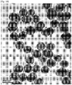
FIG. 4A is a diagram showing a TEM image of a series of f-RNPs (f-RNP 1 to 6) according to one exemplary embodiment of the present invention. -
FIG. 4B is a diagram showing an SEM image of f-RNP 5 tilted at an angle of 52° according to one exemplary embodiment of the present invention. -
FIG. 4C is a graph showing UV-visible spectra of the series of f-RNPs (f-RNP 1 to 6) according to one exemplary embodiment of the present invention. -
FIG. 4D is a diagram showing TEM-based statistical dimensional analysis results of the series of f-RNPs (f-RNP 1 to 6) according to one exemplary embodiment of the present invention. -
FIG. 5 is a diagram showing (a through d) elemental mapping images, (e) a dark-field TEM image, and (f) a HR-TEM and selected area electron diffraction (insert) image of f-RNP 5 according to one exemplary embodiment of the present invention. -
FIG. 6 includes graphs showing (a) integrated fluorescence intensities and (b) shell thicknesses and PL enhancement factors of the series of f-RNPs (f-RNP 1 to 6) according to one exemplary embodiment of the present invention. -
FIG. 7 is a graph showing fluorescence activities of the series of f-RNPs (f-RNP 1 to 6) and free Alexa Fluor™ 546 according to one exemplary embodiment of the present invention. The concentration of f-RNPs is 0.0728 nM. The highest fluorescence activity was observed for f-RNP 5. -
FIG. 8 is a diagram showing (a) a TEM image of silica-coated f-RNPs synthesized according to one exemplary embodiment of the present invention and (b) integrated fluorescence intensities of f-RNP 5 and silica-coated f-RNP 5 (Si-f-RNP 5). -
FIG. 9 is a diagram schematically showing a process of coating a surface of f-RNP with silica according to one exemplary embodiment of the present invention. A fluorescent silica shell is designed so that each of the f-RNPs exhibits higher fluorophore loading capacity as well as a fixed fluorophore location and improved stability. -
FIG. 10 is a diagram showing a TEM image of fluorescent silica-coated f-RNPs prepared according to one exemplary embodiment of the present invention. A silica-coated nanorod had a total size of approximately 150 nm, and the shape and size of a nanobar was maintained during a silica coating process. - To solve the above problems, according to an aspect of the present invention, there is provided a core-shell nanocomposite including a fluorophore disposed to have a constant distance in a vertical direction from a surface thereof, which includes nanoparticles of a first metal; a linker having a constant length, bound onto the nanoparticles of the first metal via one end thereof and having the fluorophore bound to the other end thereof; and a shell of a second metal formed on the nanoparticles of the first metal to which the linker is bound by adjusting a thickness to be spaced apart a constant distance from the fluorophore.
- According to another aspect of the present invention, there is provided a method of manufacturing a core-shell nanocomposite including a fluorophore disposed to have a constant distance from a surface thereof in a vertical direction, which includes a first step of preparing nanoparticles of a first metal; a second step of binding a linker having a constant length, which has the fluorophore bound to one end thereof, onto the nanoparticles of the first metal; and a third step of forming a shell of a second metal on the nanoparticles of the first metal to which the linker is bound by adjusting a thickness to be spaced apart a constant distance from the fluorophore.
- According to still another aspect of the present invention, there is provided a probe for metal-enhanced fluorescence including the core-shell nanocomposite according to an aspect of the present invention
- Hereinafter, the present invention will be described in detail.
- A core-shell nanocomposite according to the present invention is characterized by including a fluorophore disposed to have a constant distance in a vertical direction from a surface of a metal, thereby exhibiting a remarkable metal-enhanced fluorescence effect. In this case, it is important to 1) properly select a material of a metal shell to be introduced and 2) introduce a metal shell by adjusting a thickness of the metal shell so as to maximize a metal-enhanced fluorescence effect. When the metal shell is formed too thickly so that the fluorophore comes in contact with a surface of the metal or is too close to the surface of the metal, excitation energy may be thrown away by being conducted rather than inducing fluorescence enhancement through resonance.
- The term "metal-enhanced fluorescence (MEF)" refers to a phenomenon in which the intensity of fluorescence signals is enhanced by the interaction of a fluorophore and a metal disposed close to the fluorophore, compared to that enhanced by the fluorophore itself. Specifically, a metal-enhanced fluorescence phenomenon may occur as a result of the interaction between the fluorophore in an excited state and an induced surface plasmon on a surface of a metal. The metal-enhanced fluorescence has advantages such as 1) improved fluorescence emission efficiency, 2) enhanced detection sensitivity, 3) prevention of photobleaching of fluorescent materials, and 4) applicability to all types of molecules including endogenous and exogenous chromophores, etc. In general, a metal suitable for metal-enhanced fluorescence includes metals having a high free electron density. Also, a continuous metallic thin film may exhibit enhance fluorescence emission when a fluorophore is disposed within 100 nm from a surface of the thin film.
- Preferably, the nanoparticles of the first metal may be nanorods having an aspect ratio of 1.2 to 10. When the aspect ratio is less than 1.2, the core-shell nanocomposite may not exhibit a desired metal-enhanced fluorescence effect due to a decrease in scattering efficiency of the metal nanoparticles. On the other hand, when the aspect ratio is greater than 10, it may be difficult to control the formation of the shell of the second metal.
- Preferably, each of the first metal and the second metal may be independently gold, silver, copper, palladium, or platinum, but the present invention is not limited thereto. Examples of the metals may include materials having a metal-enhanced fluorescence effect as well known in the related art. In addition, metals capable of exhibiting a metal-enhanced fluorescence effect may be used without limitation. Preferably, the first metal and the second metal may be metals having the same or similar lattice parameters. Specifically, the first metal and the second metal may be selected from metals having a lattice parameter ratio of 1:1.4 to 1.4:1. According to aspects of the present invention, a shell of the second metal is preferably uniformly introduced onto a core of the first metal to have a constant thickness so that a fluorophore is disposed to be spaced apart a predetermined distance from a surface of the second metal. Therefore, the first metal and the second metal having the same or similar lattice parameters may be selected so that a shell of the second metal can be introduced onto nanorods of the first metal in the same lattice form with a constant thickness. For example, the metal most widely used for research on metal-enhanced fluorescence in the related art is silver. Therefore, when silver is introduced to form a shell of the second metal so as to exhibit metal-enhanced fluorescence, gold is preferably used as a material for nanoparticles of the first metal. Because gold is a highly reactive metal, it is desirable to introduce a polynucleotide having a constant length, which has a fluorophore bound to one end thereof. Also, gold has an advantage in which a silver shell may be uniformly introduced because gold has lattice parameters similar to silver.
- To dispose the fluorophore at a constant distance from the nanorods of the first metal, the polynucleotide may be used as the linker. Examples of the polynucleotide may include single- or double-stranded DNA or RNA. More preferably, the linker may be DNA. In theory, one polymer having a constant length may be used to achieve the purpose of disposing the fluorophore at a constant distance from the nanorods of the first metal. However, because the polymer is a mixture of separate polymer strands which have a constant mean molecular weight but different molecular weights, that is, different lengths, in effect, it is not easy to purely separate polymer strands having a constant length. Meanwhile, a polynucleotide having a constant length may be easily obtained by synthesizing a polynucleotide by adjusting the number of nucleotides constituting the polynucleotide. Also, the polynucleotide such as DNA and RNA may bind to another strand having complementary bonds to form a double strand. In this case, a more rigid backbone whose length is more easily controlled may be provided. Meanwhile, a polynucleotide composed of several to several tens of nucleotides may be present in the form of a somewhat rigid rod without bending even when present as a single strand. In particular, because DNA is stable even under general reaction conditions unlike RNA which is easily degraded and thus requires special reaction conditions (RNase-free conditions), DNA may be useful for introducing a fluorophore to have a constant distance according to an object of the present invention.
- Preferably, the fluorophore spaced apart a constant distance from a surface of the shell of the second metal to be exposed to the outside may be embedded by further coating an external surface of the core-shell nanocomposite with a silica shell, thereby obtaining more stable fluorescence signals. Also, the silica shell may further include a fluorophore to exhibit an additional effect of enhancing the fluorescence signals.
- According to one exemplary embodiment of the present invention, it can be seen that the core-shell nanocomposite into which a silver shell is introduced with a constant thickness after one end of thiolated DNA having a length of approximately 10 nm is labeled with
Alexa Fluor 546 as a fluorophore and the other end is bound onto the gold nanorod may exhibit a metal-enhanced fluorescence effect when the fluorophore is disposed a predetermined distance from a surface of the shell (FIGS. 6 and7 ). Also, it can be seen that the core-shell nanocomposite may have enhanced fluorescence signals having a more stable signal variation, that is, a smaller signal variation, by additionally introducing a silica shell onto the core-shell nanocomposite so that the exposed fluorophore is embedded in the silica shell to be fixed at the corresponding location (FIG. 8 ). - Further, the probe for metal-enhanced fluorescence including the core-shell nanocomposite according to the present invention is applicable to single-molecule detection due to excellent sensitivity, and thus may be effectively used as a biosensor for in vitro diagnosis of target diseases, intracellular tracking of biomaterials, in vivo imaging, solar cells, drug screening, gene sequencing, etc. when a target material or a detection material specifically binding to the target material is tagged with the probe.
- Hereinafter, configurations and effects of the present invention will be described in further detail with reference to examples thereof. It should be understood that the following examples are merely provided to aid in understanding the present invention, but not intended to limit the scope of the present invention.
- All chemical reagents (HAuCl4·3H2O, CTAB, NaBH4, L-ascorbic acid, AgNO3, sodium-dodecyl sulfate (SDS), sodium chloride (NaCl), dithiothreitol (DTT), CTAC, EtOH, MeOH, 3-aminopropyltriethoxysilane (APTES), dimethylamine, and tetraethyl orthosilicate) were purchased from Sigma-Aldrich (St. Louis, MO, USA), and used without additional purification. A HPLC-purified dye-coded thiolated oligonucleotide was purchased from IDT Inc. (Coralville, IA, USA), and reduced using dithiothreitol (0.1M) dissolved in a phosphate buffer (170 mM, pH = 8.0). Thereafter, the reduced oligonucleotide was purified though a desalting NAP-5 column (Sephadex G-25 medium, DNA grade). NANOpure H2O (>18.0 MΩ) purified using a Milli-Q water purification system was used in all experiments. Alexa Fluor™ carboxylic acid, and succinimidyl ester fluorophores were purchased from Molecular Probes (Eugene, Oregon, USA). A HR-TEM (JEM ARM 200F, JEOL, Japan, 200 kV, FEI Company, Hillsboro, Oregon, USA) equipped with a formvar/carbon-coated copper grid (Ted Pella, Inc. Redding, CA, USA) and an energy dispersive spectroscopy (EDS) unit (EDAX) were used for elemental mapping and lattice analysis, and other TEM images were obtained using JEM-2100 (JEOL, Japan, 200 kV). An inductively coupled plasma emission spectrometer (ICP-ES, ICPS-7510, Shimadzu, Japan) was used to measure a mass concentration of the prepared gold nanorods (AuNRs), and a NanoDrop 3300 fluorospectrometer was used to measure nanodrops. The shape of the formed gold nanorods was observed using a field-emission scanning electron microscope (FE-SEM,
Helios 650, FEI, USA). - AuNRs having an aspect ratio value of approximately 4.0 were manufactured using a slightly modified seed-mediated method known in the art. Specifically, a seed was prepared by mixing 5 mL of a 0.5 mM HAuCl4· 3H2O solution with 5 mL of 0.2 M CTAB, and 600 µL of an ice cold 0.01 M NaBH4 solution was rapidly added thereto. The seed solution was used 2 hours after the reduction step. 5 mL of a 0.5 mM HAuCl4·3H2O solution was mixed with 5 mL of a 0.2 M CTAB solution, 200 µL of an AgNO3 solution was added, and 70 µL of 78 mM L-ascorbic acid was then added thereto. After the resulting mixture was gently mixed, 12 µL of the seed solution prepared in advance was added, and the mixture was then incubated for at least 4 hours to obtain AuNRs. The AuNRs thus prepared were analyzed using TEM, UV-Vis spectrometry and an ICP-AES assay. The sizes and aspect ratios of 202 AuNRs were analyzed using ImageJ software. The AuNRs had a size of 50.32 (± 4.26) nm × 12.81 (± 0.94) nm and an aspect ratio value of 3.95 (± 0.42). It was revealed that a molar extinction coefficient (ε) calculated at 520 nm was 1.374 × 10⁹, and the absorbance at 520 nm was 0.249 when analyzed using ICP-AES. From these results, it was confirmed that a gold concentration of the prepared AuNRs solution was 69.5 µM. Transverse and longitudinal modes were observed at 510 and 765 nm, respectively (
FIG. 2 ). - An Alexa Fluor™ 546-modified thiolated oligonucleotide (DNA) was bound to a surface of AuNRs synthesized in Example 1. First, 1,500 µL of a newly reduced Alexa Fluor™ 546-modified thiolated oligonucleotide solution and 67.8 µL of a 10% SDS solution were mixed with 4,500 µL of a 1.16 nM AuNR solution. The mixed solution was incubated at room temperature for 30 minutes. Thereafter, the solution was diluted with a 100 mM phosphate buffer to reach a final phosphate concentration of 10 mM (pH 7.4), and then incubated at room temperature for 30 minutes. Three aliquots of 2 M NaCl (10 mM PB, 0.1% SDS) were added to boiling water every 20 minutes to form a 0.3 M NaCl solution. An hour after the final addition, the formed colloidal solution was centrifuged twice (at 9,500 rpm for 10 min), and the precipitate was re-dispersed in deionized water. Prior to a shell growth step, an optical density (OD) of DNA-modified particles was measured by a UV-vis spectrophotometer at 520 nm to determine a concentration of the DNA-modified particles.
- To determine the number of dye-labeled oligonucleotides loaded on each AuNR particle, a concentration of AuNR nanoparticles and a concentration of fluorescent oligonucleotides in each sample were measured. To determine the concentration of an AuNR solution in each aliquot, a UV-visble spectrophotometer was used. The concentration of AuNR was directly associated with an absorbance value through Lambert-Beer's law (A = εbc). The molar extinction coefficient used in the present invention was 1.374 M-1cm-1 at 520 nm. To determine the concentration of the fluorescent oligonucleotides in each aliquot, 100 µL of the modified oligonucleotides in the AuNR solution was mixed with an equal volume of a 100 mM KCN solution to destroy an AuNR lattice structure, thereby separating the oligonucleotides from a surface of AuNR. In this step, the concentration of the oligonucleotides was diluted two-fold. The mixed solution was incubated to release the oligonucleotides into the solution and a supernatant was obtained to measure fluorescence intensity. The fluorescence intensity was compared to a free Alexa Fluor™ 546-modified thiolated oligonucleotide-based standard curve, and three different batches were measured to obtain a standard deviation (
FIG. 3 ). For fluorescence measurement, the fluorophore was excited at 510 nm to measure fluorescence. As a result, it was confirmed that, on average, 293.4 fluorescent oligonucleotides were bound onto one AuNR particle. - An Ag shell was formed on fluorescence-labeled DNA-modified AuNRs (DNA-AuNRs) and a thickness of the Ag shell was gradually increased. The AuNR solution prepared in Example 2 was diluted so that the OD at 520 nm became 0.5. A diluted AuNR solution (100 µL) was sequentially mixed with CTAC, AgNO3 and a 0.1 M L-ascorbic acid solution, and the resulting mixture was incubated at 60 °C for 3 hours. The concentrations of the added reagents were sequentially 2.5 mM (f-RNP 1), 5.0 mM (f-RNP 2), 7.5 mM (f-RNP 3), 10.0 mM (f-RNP 4), 15.0 mM (f-RNP 5) and 20.0 mM (f-RNP 6) CTAC; and 0.25, 0.50, 0.75, 1.0, 1.5 and 2.0 mM AgNO3, respectively. Specifically, the concentrations of CTAC and AgNO3 increased while a molar ratio between CTAC and AgNO3 was maintained at 10 to prepare a series of samples. After incubation, the resulting solutions were centrifuged at 7,000 rpm (f-
RNP 1 and f-RNP 2), 6,000 rpm (f-RNP 3 and f-RNP 4) or 5,000 rpm (f-RNP 5 and f-RNP 6) for 10 minutes, and re-dispersed in deionized water. The manufactured fluorescence-labeled DNA-modified AuNRs having a shell formed on surfaces thereof were named fluorescent DNA-functionalized plasmonic rectangular nanoparallelepipeds, which were hereinafter abbreviated as f-RNPs. Each of the samples was distinguished by a number after the abbreviated name described above. - 3.5 µL of 0.2% 3-aminopropyltriethoxysilane (APTES) (v/v, an EtOH solution) was mixed with 62.5 µL of DMF and 8.4 µL of 0.8 mM carboxylic succinimidyl ester-tagged Alexa Fluor™ 546 (a MeOH solution). The resulting mixture was incubated at room temperature for 12 hours, and 700 µL of ethanol and 53.3 µL of a dimethylamine solution were added thereto. After 4 hours, 750 µL of the solution was mixed with 50 µL of 1.82 nM f-RNP 5 (a distilled water solution), and incubated for 30 minutes. Thereafter, 2 µL of 10% tetraethyl orthosilicate (v/v, an EtOH solution) was added thereto, and the resulting solution was incubated for another two and a half hours. The solution was centrifuged twice (at 5,000 rpm for 15 minutes), washed, and then re-dispersed in deionized water.
- The spectroscopic and morphological characteristics of f-RNPs were analyzed using a UV-visible spectrometer and TEM (
FIG. 4 ). As an amount of a used Ag precursor increased, a remarkable spectroscopic change was observed. The f-RNPs 1 to 3 were compared with the AuNRs, and a wider transverse peak (at 510 nm) and a wider longitudinal peak (at 765 nm) were observed. As an amount of the used Ag precursor increased, the intensities of the two peaks also increased (FIG. 4C ). From the TEM image (FIG. 4A ), it was confirmed that the Ag shells had nearly identical thicknesses in both longitudinal and transverse directions in the case of the series of f-RNPs according to the present invention. It is known that the AuNRs having an aspect ratio of 3 to 7 have a [001] longitudinal growth direction; and an octagonal cross section enclosed by {100} and {110} facets, and {110} and {111} facets are exposed through a truncated region at an end side thereof. Initially, the thermodynamically induced conformal overgrowth occurred at the end and lateral regions of the AuNR. When an Ag growth step is proceeded using a CTAC capping agent, the {110} and {111} facets of the AuNR have a higher epitaxial growth rate than a {100} facet. - As the Ag shell grew, the Au-Ag core-shell particles were gradually surrounded by the {100} facet of Ag which is strongly bound to the capping agent, and the CTAC. For the f-
RNPs 3 through 6, the Ag shells grew thicker in a transverse direction than in a longitudinal direction, and the f-RNPs had relatively sharp edges (FIG. 4A ). Also, a rectangular parallelepiped 3-D shape of f-RNP 5 was determined using field-emission scanning electron microscopy measurement using a 52° tilt (FIG. 4B ). From these results, it was confirmed that an end of the core-shell particle was more rapidly surrounded by the {100} facet, compared to the lateral regions. The CTAC strongly bound to a surface of Ag was able to block shell growth to induce a difference in shell growth rate between transverse and longitudinal directions of the core-shell particles after the f-RNP 3. Four distinct plasmonic modes were observed at 280 nm, 390 nm, 440 nm and 580 nm in the UV-visible spectrum (FIG. 4C ). In particular, the plasmonic modes at 280 and 390 nm represent two distinct Ag shell formations (in longitudinal and transverse directions), and the plasmonic modes at 440 and 580 nm may account for transverse and longitudinal modes of the f-RNPs. - Also, specific TEM analysis was performed using ImageJ software (rsb.info.nih.gov/ij/;
FIG. 4D ). For each of the f-RNP structures, at least 100 particles were measured. The transverse and longitudinal lengths of f-RNPs increased from 12.8 nm to 36.1 nm and from 50.3 nm to 60.4 nm, respectively, indicating that the thickness of the Ag shell is generally increased in a transverse direction. Mean transverse and longitudinal shell thicknesses were calculated by subtracting an AuNR dimension from the measured dimension of each of the f-RNPs. The transverse and longitudinal shell thicknesses were 11.6 and 5.0 nm, respectively. The transverse shell thickness (11.6 nm) of f-RNP 6 was similar to a theoretical length of the Alexa Fluor™ 546-modified thiolated oligonucleotide, whereas the longitudinal length of f-RNP 6 was much shorter than a theoretical length of the fluorescent oligonucleotide. The aspect ratios of the f-RNPs gradually decreased as the thickness of the formed Ag shell increased (FIG. 4D ). - To further analyze the structural characteristics of the f-RNPs, an elemental mapping image and lattice information of f-
RNP 5 were obtained (FIG. 5 ). The results generally showed that the AuNR core and the Ag shell were clearly separated without intermixing between Au and Ag elements. The rectangular parallelepiped structures having well-defined sharp Ag corners were additionally confirmed on the dark-field TEM image (FIG. 5E). FIG. 5F shows a high-resolution TEM (HR-TEM) image and selected area electron diffraction (SAED) results. Clear and continuous fringes having a [001] lattice zone axis with a distance of 2.0 Å and capable of being indexed with {200} of face-centered cubic (fcc) Ag were observed on the HR-TEM image. The corresponding SAED patterns indicated square symmetry spots. From these results, it was confirmed that the Ag shell had a single crystal structure surrounded by the {100} facet. It can be seen that clear edges were observed in Ag shell corner regions on the HR-TEM image showing rectangular sections merged by the {100} facet. - Next, fluorescence signal enhancement for 2 µL of an f-RNP solution was measured using a NanoDrop 3300 fluorospectrometer (
FIGS. 6 and7 ). An integrated fluorescence intensity plot showed that the intensity of the fluorescence signal increased linearly as the Ag shell grew, from f-RNPs 3 through 5. For the f-RNP 6 having a transverse Ag shell having a thickness of approximately 12 nm, the fluorescence signals started to decrease when a fluorophore dye and the Ag shell were close to or in contact with each other. This indicates that the Ag shell is preferably formed in a state in which the fluorophore dye and the Ag shell were maintained at a proper distance apart, considering that a main difference betweenRNP 5 andRNP 6 arose from the transverse Ag shell thickness. Photoluminescence (PL) enhancement factors of the f-RNPs were calculated from the measured fluorescence intensities. The fluorescence signals of the f-RNPs were compared with the fluorescence signal of the free Alexa Fluor™ 546-modified thiolated oligonucleotide to obtain a PL enhancement factor for each of the f-RNP structures (FIG. 6B ). The PL enhancement factor is defined as follows:
Alexa Fluor™ 546 in a solution. IPL and CPL represent an integrated PL intensity and a concentration of a free Alexa Fluor™ 546-modified thiolated oligonucleotide. Based on the results, it was confirmed that f-RNP 5 having transverse and longitudinal Ag shell thicknesses of 9.64 nm and 4.81 nm on a gold nanorod bound to DNA having a length of approximately 15 bp and a fluorophore labeled at one end, is a nanoprobe suitable for MEF, and the MEF enhancement factor for the f-RNP 5 probe in the solution was approximately 300. - In addition, it was confirmed that the particle stability and biological toxicity of the f-RNPs were able to be improved when the particles were coated with the silica shell. In general, an Ag surface exposed to phosphate-buffered saline (PBS) or human serum is able to cause particle instability. Also, a deviation of the measured fluorescence signals increased when a distance between the fluorophore dye and the surface of the metal is fixed or variable due to the movement of the dye. After searching for optimal thickness of the Ag shell for MEF, a silica shell was formed so that the fluorophore was fixed at an optimized fluorophore location of f-RNPs, and the fluorophore was embedded in the silica shell to minimize a fluorescence signal fluctuation in a single particle and a fluorescence signal fluctuation from particle to particle (
FIG. 1B ). - In a representative experiment for forming the silica shell, 3.5 µL of 0.2 % (v/v, in EtOH) APTES was mixed with 762.5 µL of EtOH and 53.3 µL of a dimethylamine solution. After the resulting solution was kept at room temperature for 4 hours, 750 µL of the solution was mixed with 50 µL of a 1.82 nM f-
RNP 5 solution dissolved in distilled water, and the mixed solution was additionally incubated at room temperature for 30 minutes. Thereafter, 2 µL of 10 % (v/v, in EtOH) tetraethyl orthosilicate was added thereto, and the resulting solution was incubated at room temperature for 2.5 hours. The solution was centrifuged twice (at 5, 000 rpm for 15 minutes), and then re-dispersed in deionized water. A TEM image was measured to determine whether a silica shell was formed on f-RNPs (FIG. 8A ). As a result, the f-RNPs were completely enclosed by the silica shell, and almost all the silica shells included the f-RNPs. Next, differences in fluorescence signal intensity and reproducibility activity between f-RNP 5 and silica-coated f-RNP 5 (Si-f-RNP 5) were determined. As a result, the fluorescence signal intensities were very similar before and after silica coating. However, a standard deviation of the fluorescence signal intensity of Si-f-RNP 5 decreased compared to the f-RNP 5, indicating that the signal reproducibility was able to be further improved through silica shell formation (approximate 2-fold improvement in standard deviation;FIG. 8B ). In this case, when additional fluorescent molecules were embedded in the silica shell for coating during a process of forming the silica shell, the fluorescence intensity of each of the particles was able to be further improved (FIGS. 9 and10 ). - To summarize, the present inventors developed a synthetic strategy for screening an optimal RNP probe for MEF by using fluorescence-labeled DNA whose length was adjustable and adjusting a thickness of a silver shell formed by precisely regulating the shell-forming chemistry to adjust a distance between a labeled fluorophore and a surface of the silver shell on the DNA. For this purpose, the structural and optical characteristics of f-RNPs were specifically analyzed. It was revealed that a PL enhancement factor of approximately 300 for the solution samples was realized under the optimized conditions. In addition, the present inventors confirmed that the stability and signal reproducibility of the probe was improved through formation of the silica shell on the f-RNPs. The Si-f-RNP structure may be a promising platform for practical use of the MEF probe. The present inventors expect that the strategies and results according to the present invention provide benefits for use of the MEF probe in better understanding of the MEF probe, reliable quantitative research using the MEF probe, chemical and biological detection, and bio-imaging applications.
Claims (15)
- A core-shell nanocomposite comprising a fluorophore disposed to have a constant distance in a vertical direction from a surface thereof, comprising:nanoparticles of a first metal;a linker having a constant length, bound onto nanoparticles of the first metal via one end thereof and having the fluorophore bound to the other end thereof; anda shell of a second metal formed on the nanoparticles of the first metal to which the linker is bound by adjusting a thickness to be spaced apart a constant distance from the fluorophore.
- The core-shell nanocomposite of claim 1, which has a metal-enhanced fluorescence effect.
- The core-shell nanocomposite of claim 1, wherein the nanoparticles of the first metal comprise nanorods having an aspect ratio of 1.2 to 10.
- The core-shell nanocomposite of claim 1, wherein the first metal and the second metal are each independently gold, silver, copper, palladium, or platinum.
- The core-shell nanocomposite of claim 4, wherein the first metal and the second metal have a lattice parameter ratio of 1:1.4 to 1.4:1.
- The core-shell nanocomposite of claim 1, wherein the linker is single- or double-stranded DNA or RNA.
- The core-shell nanocomposite of claim 1, wherein the fluorophore is further coated with a silica shell so that the fluorophore is embedded in a state in which the fluorophore maintains a constant distance from a surface of the shell of the second metal.
- The core-shell nanocomposite of claim 7, wherein the silica shell further comprises a fluorophore.
- A method of manufacturing a core-shell nanocomposite comprising a fluorophore disposed to have a constant distance from a surface thereof in a vertical direction, comprising:a first step of preparing nanoparticles of a first metal;a second step of binding a linker having a constant length, which has the fluorophore bound to one end thereof, onto the nanoparticles of the first metal; anda third step of forming a shell of a second metal on the nanoparticles of the first metal to which the linker is bound by adjusting a thickness to be spaced apart a constant distance from the fluorophore.
- The method of claim 9, wherein the nanoparticles of the first metal comprise nanorods having an aspect ratio of 1.2 to 10.
- The method of claim 9, wherein each of the first metal and the second metal is independently gold, silver, copper, palladium, or platinum.
- The method of claim 9, wherein the first metal and the second metal have a lattice parameter ratio of 1:1.4 to 1.4:1.
- The method of claim 9, wherein the linker is single- or double-stranded DNA or RNA.
- The method of claim 9, further comprising a fourth step of coating the core-shell nanocomposite with a silica shell which further comprises or not comprises a fluorophore.
- A probe for metal-enhanced fluorescence containing the core-shell nanocomposite defined in any one of claims 1 to 8.
Applications Claiming Priority (2)
| Application Number | Priority Date | Filing Date | Title |
|---|---|---|---|
| KR1020140060090A KR101597894B1 (en) | 2014-05-20 | 2014-05-20 | Core-shell nanocomplex for metal-enhanced fluorescence |
| PCT/KR2015/005067 WO2015178688A1 (en) | 2014-05-20 | 2015-05-20 | Core-shell nanocomposite for metal-enhanced fluorescence |
Publications (3)
| Publication Number | Publication Date |
|---|---|
| EP3272831A1 true EP3272831A1 (en) | 2018-01-24 |
| EP3272831A4 EP3272831A4 (en) | 2018-04-18 |
| EP3272831B1 EP3272831B1 (en) | 2019-07-10 |
Family
ID=54554284
Family Applications (1)
| Application Number | Title | Priority Date | Filing Date |
|---|---|---|---|
| EP15796131.9A Active EP3272831B1 (en) | 2014-05-20 | 2015-05-20 | Core-shell nanocomposite for metal-enhanced fluorescence |
Country Status (5)
| Country | Link |
|---|---|
| US (1) | US11060021B2 (en) |
| EP (1) | EP3272831B1 (en) |
| KR (1) | KR101597894B1 (en) |
| ES (1) | ES2749101T3 (en) |
| WO (1) | WO2015178688A1 (en) |
Cited By (1)
| Publication number | Priority date | Publication date | Assignee | Title |
|---|---|---|---|---|
| CN110726708A (en) * | 2019-10-24 | 2020-01-24 | 深圳大学 | Quantitative detection method for shell dissipation condition in core-shell structure |
Families Citing this family (5)
| Publication number | Priority date | Publication date | Assignee | Title |
|---|---|---|---|---|
| EP3300128B1 (en) * | 2016-09-21 | 2021-03-03 | Vestel Elektronik Sanayi ve Ticaret A.S. | Phosphor arrangement and method |
| KR101917439B1 (en) * | 2016-12-14 | 2018-11-12 | 서울대학교산학협력단 | A metallic nanostructures having a cube-in-cube shape, a method for prepaing the same, and use thereof |
| KR20190091185A (en) | 2018-01-26 | 2019-08-05 | 서울대학교산학협력단 | Method for preparing a metal nanocube with a modulated corner sharpness index |
| KR102687587B1 (en) | 2021-09-27 | 2024-07-22 | 삼성전자주식회사 | Nanostruture including quantum dot, compositie includingg nanostruture, display panel and electronic device including the composite |
| KR102667684B1 (en) | 2023-07-10 | 2024-06-10 | 한국화학연구원 | Silver nanoparticle-deposited ZnO nanostructure for fluorescence enhancement of fluorescence-labelled DNA probe, method for manufacturing the same and fluorescence signal detect method therof |
Family Cites Families (10)
| Publication number | Priority date | Publication date | Assignee | Title |
|---|---|---|---|---|
| JP4482343B2 (en) | 2003-02-07 | 2010-06-16 | 日本ペイント株式会社 | Composite metal colloidal particles and solution, and method for producing the same |
| JP5117679B2 (en) | 2005-04-27 | 2013-01-16 | 株式会社リコー | Dye material using multiphoton absorption material, method for producing dye material, multiphoton absorption reaction material, reaction product of multiphoton absorption reaction material, multiphoton absorption reaction aid, and dye solution |
| JP5057663B2 (en) | 2005-10-19 | 2012-10-24 | 富士フイルム株式会社 | Manufacturing method of shape anisotropic metal fine particles, coloring composition, photosensitive transfer material, substrate with black image, color filter, and liquid crystal display element |
| US8569468B2 (en) * | 2006-09-14 | 2013-10-29 | The Regents Of The University Of California | Nanoplasmonic molecular ruler for nuclease activity and DNA footprinting |
| US20080066549A1 (en) * | 2006-09-18 | 2008-03-20 | Oldham Mark F | Methods, systems and apparatus for light concentrating mechanisms |
| US9023372B2 (en) | 2007-07-18 | 2015-05-05 | University Of Maryland | Metal-enhanced fluorescence nanoparticles |
| KR101153748B1 (en) * | 2008-05-07 | 2012-06-14 | 재단법인서울대학교산학협력재단 | NOVEL Au/Ag CORE SHELL COMPOSITE USEFUL FOR BIOSENNOVEL Au/Ag CORE SHELL COMPOSITE USEFUL FOR BIOSENSOR SOR |
| JP2010197746A (en) | 2009-02-25 | 2010-09-09 | Ricoh Co Ltd | Multiphoton absorbing material, reaction aid, and method of manufacturing these |
| RU2542386C2 (en) | 2009-12-11 | 2015-02-20 | Корея Рисерч Инститьют Оф Кемикал Текнолоджи | Dimeric occludant nanostructure, labelled with molecule, active with respect to raman scattering, located in inter-particle compound, application and method of obtaining thereof |
| KR101352342B1 (en) | 2010-11-24 | 2014-02-17 | 서울대학교산학협력단 | Intra-nanogapped core-shell nanoparticle and preparation method thereof |
-
2014
- 2014-05-20 KR KR1020140060090A patent/KR101597894B1/en active Active
-
2015
- 2015-05-20 ES ES15796131T patent/ES2749101T3/en active Active
- 2015-05-20 EP EP15796131.9A patent/EP3272831B1/en active Active
- 2015-05-20 WO PCT/KR2015/005067 patent/WO2015178688A1/en not_active Ceased
- 2015-05-20 US US15/542,439 patent/US11060021B2/en active Active
Cited By (2)
| Publication number | Priority date | Publication date | Assignee | Title |
|---|---|---|---|---|
| CN110726708A (en) * | 2019-10-24 | 2020-01-24 | 深圳大学 | Quantitative detection method for shell dissipation condition in core-shell structure |
| CN110726708B (en) * | 2019-10-24 | 2022-06-07 | 深圳大学 | Quantitative detection method for shell dissipation condition in core-shell structure |
Also Published As
| Publication number | Publication date |
|---|---|
| EP3272831A4 (en) | 2018-04-18 |
| WO2015178688A1 (en) | 2015-11-26 |
| US11060021B2 (en) | 2021-07-13 |
| ES2749101T3 (en) | 2020-03-19 |
| KR101597894B1 (en) | 2016-02-26 |
| KR20150133873A (en) | 2015-12-01 |
| EP3272831B1 (en) | 2019-07-10 |
| US20180044584A1 (en) | 2018-02-15 |
Similar Documents
| Publication | Publication Date | Title |
|---|---|---|
| Yaraki et al. | Metal nanoparticles‐enhanced biosensors: synthesis, design and applications in fluorescence enhancement and surface‐enhanced Raman scattering | |
| EP3272831B1 (en) | Core-shell nanocomposite for metal-enhanced fluorescence | |
| Fales et al. | Silver embedded nanostars for SERS with internal reference (SENSIR) | |
| Hwang et al. | DNA-engineerable ultraflat-faceted core–shell nanocuboids with strong, quantitative plasmon-enhanced fluorescence signals for sensitive, reliable microRNA detection | |
| Vo-Dinh et al. | Plasmonic nanoprobes: from chemical sensing to medical diagnostics and therapy | |
| Mayer et al. | A single molecule immunoassay by localized surface plasmon resonance | |
| US10254230B2 (en) | Nanoparticles in the shape of nanosnowman with a head part and a body part, a preparation method thereof and a detection method using the same | |
| Volkert et al. | Salt-mediated self-assembly of thioctic acid on gold nanoparticles | |
| EP2645104B1 (en) | Single nanoparticle having a nanogap between a core material and a shell material, and preparation method thereof | |
| Yuan et al. | Plasmon coupling-enhanced two-photon photoluminescence of Au@ Ag core–shell nanoparticles and applications in the nuclease assay | |
| US12109620B2 (en) | Plasmonic nanoparticles with intra-nanogap produced by dealloying, method for preparing the same and use thereof | |
| Yan et al. | High-throughput single-particle analysis of metal-enhanced fluorescence in free solution using Ag@ SiO2 core–shell nanoparticles | |
| Li et al. | Silver decahedral nanoparticles-enhanced fluorescence resonance energy transfer sensor for specific cell imaging | |
| Jia et al. | DNA precisely regulated Au nanorods/Ag2S quantum dots satellite structure for ultrasensitive detection of prostate cancer biomarker | |
| Fu et al. | A self-assembled chiral-aptasensor for ATP activity detection | |
| US8815158B2 (en) | Granular nanoparticles having bright fluorescence and giant raman enhancements | |
| Guo et al. | Multifunctional optical probe based on gold nanorods for detection and identification of cancer cells | |
| Pan et al. | Au@ Ag nanoparticle sensor for sensitive and rapid detection of glucose | |
| Zhang et al. | Synthesis of size-tunable chitosan encapsulated gold–silver nanoflowers and their application in SERS imaging of living cells | |
| CN107219213B (en) | Method for detecting bisphenol A by using surface effect of enzyme-guided crystal growth enhanced Raman spectrum | |
| Zhou et al. | Controllable synthesis of multi-tip spatial gold nanostructures to facilitate SPR enhancement for exosomal PD-L1 assay | |
| Crew et al. | DNA assembly and enzymatic cutting in solutions: A gold nanoparticle based SERS detection strategy | |
| Xia et al. | Metal-enhanced fluorescence using aggregated silver nanoparticles | |
| KR20200141575A (en) | Method for detecting target material by SERS using assembly of metal nanocubes with hierarchical structure | |
| Tu et al. | Fluorescence and scattering dual-mode multiplexed imaging with gold–silver alloy core silica shell nanoparticles |
Legal Events
| Date | Code | Title | Description |
|---|---|---|---|
| STAA | Information on the status of an ep patent application or granted ep patent |
Free format text: STATUS: THE INTERNATIONAL PUBLICATION HAS BEEN MADE |
|
| STAA | Information on the status of an ep patent application or granted ep patent |
Free format text: STATUS: THE APPLICATION IS DEEMED TO BE WITHDRAWN |
|
| PUAI | Public reference made under article 153(3) epc to a published international application that has entered the european phase |
Free format text: ORIGINAL CODE: 0009012 |
|
| STAA | Information on the status of an ep patent application or granted ep patent |
Free format text: STATUS: REQUEST FOR EXAMINATION WAS MADE |
|
| 17P | Request for examination filed |
Effective date: 20170725 |
|
| 18D | Application deemed to be withdrawn |
Effective date: 20161221 |
|
| AK | Designated contracting states |
Kind code of ref document: A1 Designated state(s): AL AT BE BG CH CY CZ DE DK EE ES FI FR GB GR HR HU IE IS IT LI LT LU LV MC MK MT NL NO PL PT RO RS SE SI SK SM TR |
|
| D18D | Application deemed to be withdrawn (deleted) | ||
| A4 | Supplementary search report drawn up and despatched |
Effective date: 20180321 |
|
| RIC1 | Information provided on ipc code assigned before grant |
Ipc: C09K 11/58 20060101ALI20180315BHEP Ipc: C09K 11/06 20060101ALI20180315BHEP Ipc: G01N 21/64 20060101ALI20180315BHEP Ipc: C09K 11/02 20060101AFI20180315BHEP Ipc: G01N 33/58 20060101ALI20180315BHEP Ipc: G01N 33/543 20060101ALI20180315BHEP |
|
| GRAP | Despatch of communication of intention to grant a patent |
Free format text: ORIGINAL CODE: EPIDOSNIGR1 |
|
| STAA | Information on the status of an ep patent application or granted ep patent |
Free format text: STATUS: GRANT OF PATENT IS INTENDED |
|
| INTG | Intention to grant announced |
Effective date: 20181214 |
|
| GRAS | Grant fee paid |
Free format text: ORIGINAL CODE: EPIDOSNIGR3 |
|
| GRAA | (expected) grant |
Free format text: ORIGINAL CODE: 0009210 |
|
| STAA | Information on the status of an ep patent application or granted ep patent |
Free format text: STATUS: THE PATENT HAS BEEN GRANTED |
|
| AK | Designated contracting states |
Kind code of ref document: B1 Designated state(s): AL AT BE BG CH CY CZ DE DK EE ES FI FR GB GR HR HU IE IS IT LI LT LU LV MC MK MT NL NO PL PT RO RS SE SI SK SM TR |
|
| REG | Reference to a national code |
Ref country code: GB Ref legal event code: FG4D |
|
| REG | Reference to a national code |
Ref country code: CH Ref legal event code: EP Ref country code: AT Ref legal event code: REF Ref document number: 1153568 Country of ref document: AT Kind code of ref document: T Effective date: 20190715 |
|
| REG | Reference to a national code |
Ref country code: DE Ref legal event code: R096 Ref document number: 602015033627 Country of ref document: DE |
|
| REG | Reference to a national code |
Ref country code: IE Ref legal event code: FG4D |
|
| REG | Reference to a national code |
Ref country code: NL Ref legal event code: MP Effective date: 20190710 |
|
| REG | Reference to a national code |
Ref country code: LT Ref legal event code: MG4D |
|
| REG | Reference to a national code |
Ref country code: AT Ref legal event code: MK05 Ref document number: 1153568 Country of ref document: AT Kind code of ref document: T Effective date: 20190710 |
|
| PG25 | Lapsed in a contracting state [announced via postgrant information from national office to epo] |
Ref country code: NL Free format text: LAPSE BECAUSE OF FAILURE TO SUBMIT A TRANSLATION OF THE DESCRIPTION OR TO PAY THE FEE WITHIN THE PRESCRIBED TIME-LIMIT Effective date: 20190710 Ref country code: AT Free format text: LAPSE BECAUSE OF FAILURE TO SUBMIT A TRANSLATION OF THE DESCRIPTION OR TO PAY THE FEE WITHIN THE PRESCRIBED TIME-LIMIT Effective date: 20190710 Ref country code: PT Free format text: LAPSE BECAUSE OF FAILURE TO SUBMIT A TRANSLATION OF THE DESCRIPTION OR TO PAY THE FEE WITHIN THE PRESCRIBED TIME-LIMIT Effective date: 20191111 Ref country code: SE Free format text: LAPSE BECAUSE OF FAILURE TO SUBMIT A TRANSLATION OF THE DESCRIPTION OR TO PAY THE FEE WITHIN THE PRESCRIBED TIME-LIMIT Effective date: 20190710 Ref country code: BG Free format text: LAPSE BECAUSE OF FAILURE TO SUBMIT A TRANSLATION OF THE DESCRIPTION OR TO PAY THE FEE WITHIN THE PRESCRIBED TIME-LIMIT Effective date: 20191010 Ref country code: NO Free format text: LAPSE BECAUSE OF FAILURE TO SUBMIT A TRANSLATION OF THE DESCRIPTION OR TO PAY THE FEE WITHIN THE PRESCRIBED TIME-LIMIT Effective date: 20191010 Ref country code: LT Free format text: LAPSE BECAUSE OF FAILURE TO SUBMIT A TRANSLATION OF THE DESCRIPTION OR TO PAY THE FEE WITHIN THE PRESCRIBED TIME-LIMIT Effective date: 20190710 Ref country code: HR Free format text: LAPSE BECAUSE OF FAILURE TO SUBMIT A TRANSLATION OF THE DESCRIPTION OR TO PAY THE FEE WITHIN THE PRESCRIBED TIME-LIMIT Effective date: 20190710 Ref country code: FI Free format text: LAPSE BECAUSE OF FAILURE TO SUBMIT A TRANSLATION OF THE DESCRIPTION OR TO PAY THE FEE WITHIN THE PRESCRIBED TIME-LIMIT Effective date: 20190710 |
|
| PG25 | Lapsed in a contracting state [announced via postgrant information from national office to epo] |
Ref country code: LV Free format text: LAPSE BECAUSE OF FAILURE TO SUBMIT A TRANSLATION OF THE DESCRIPTION OR TO PAY THE FEE WITHIN THE PRESCRIBED TIME-LIMIT Effective date: 20190710 Ref country code: AL Free format text: LAPSE BECAUSE OF FAILURE TO SUBMIT A TRANSLATION OF THE DESCRIPTION OR TO PAY THE FEE WITHIN THE PRESCRIBED TIME-LIMIT Effective date: 20190710 Ref country code: RS Free format text: LAPSE BECAUSE OF FAILURE TO SUBMIT A TRANSLATION OF THE DESCRIPTION OR TO PAY THE FEE WITHIN THE PRESCRIBED TIME-LIMIT Effective date: 20190710 Ref country code: IS Free format text: LAPSE BECAUSE OF FAILURE TO SUBMIT A TRANSLATION OF THE DESCRIPTION OR TO PAY THE FEE WITHIN THE PRESCRIBED TIME-LIMIT Effective date: 20191110 Ref country code: GR Free format text: LAPSE BECAUSE OF FAILURE TO SUBMIT A TRANSLATION OF THE DESCRIPTION OR TO PAY THE FEE WITHIN THE PRESCRIBED TIME-LIMIT Effective date: 20191011 |
|
| REG | Reference to a national code |
Ref country code: CH Ref legal event code: NV Representative=s name: VALIPAT S.A. C/O BOVARD SA NEUCHATEL, CH |
|
| REG | Reference to a national code |
Ref country code: ES Ref legal event code: FG2A Ref document number: 2749101 Country of ref document: ES Kind code of ref document: T3 Effective date: 20200319 |
|
| PG25 | Lapsed in a contracting state [announced via postgrant information from national office to epo] |
Ref country code: TR Free format text: LAPSE BECAUSE OF FAILURE TO SUBMIT A TRANSLATION OF THE DESCRIPTION OR TO PAY THE FEE WITHIN THE PRESCRIBED TIME-LIMIT Effective date: 20190710 |
|
| PG25 | Lapsed in a contracting state [announced via postgrant information from national office to epo] |
Ref country code: PL Free format text: LAPSE BECAUSE OF FAILURE TO SUBMIT A TRANSLATION OF THE DESCRIPTION OR TO PAY THE FEE WITHIN THE PRESCRIBED TIME-LIMIT Effective date: 20190710 Ref country code: EE Free format text: LAPSE BECAUSE OF FAILURE TO SUBMIT A TRANSLATION OF THE DESCRIPTION OR TO PAY THE FEE WITHIN THE PRESCRIBED TIME-LIMIT Effective date: 20190710 Ref country code: DK Free format text: LAPSE BECAUSE OF FAILURE TO SUBMIT A TRANSLATION OF THE DESCRIPTION OR TO PAY THE FEE WITHIN THE PRESCRIBED TIME-LIMIT Effective date: 20190710 |
|
| PG25 | Lapsed in a contracting state [announced via postgrant information from national office to epo] |
Ref country code: SM Free format text: LAPSE BECAUSE OF FAILURE TO SUBMIT A TRANSLATION OF THE DESCRIPTION OR TO PAY THE FEE WITHIN THE PRESCRIBED TIME-LIMIT Effective date: 20190710 Ref country code: IS Free format text: LAPSE BECAUSE OF FAILURE TO SUBMIT A TRANSLATION OF THE DESCRIPTION OR TO PAY THE FEE WITHIN THE PRESCRIBED TIME-LIMIT Effective date: 20200224 Ref country code: CZ Free format text: LAPSE BECAUSE OF FAILURE TO SUBMIT A TRANSLATION OF THE DESCRIPTION OR TO PAY THE FEE WITHIN THE PRESCRIBED TIME-LIMIT Effective date: 20190710 Ref country code: SK Free format text: LAPSE BECAUSE OF FAILURE TO SUBMIT A TRANSLATION OF THE DESCRIPTION OR TO PAY THE FEE WITHIN THE PRESCRIBED TIME-LIMIT Effective date: 20190710 |
|
| REG | Reference to a national code |
Ref country code: DE Ref legal event code: R097 Ref document number: 602015033627 Country of ref document: DE |
|
| PLBE | No opposition filed within time limit |
Free format text: ORIGINAL CODE: 0009261 |
|
| STAA | Information on the status of an ep patent application or granted ep patent |
Free format text: STATUS: NO OPPOSITION FILED WITHIN TIME LIMIT |
|
| PG2D | Information on lapse in contracting state deleted |
Ref country code: IS |
|
| 26N | No opposition filed |
Effective date: 20200603 |
|
| PG25 | Lapsed in a contracting state [announced via postgrant information from national office to epo] |
Ref country code: SI Free format text: LAPSE BECAUSE OF FAILURE TO SUBMIT A TRANSLATION OF THE DESCRIPTION OR TO PAY THE FEE WITHIN THE PRESCRIBED TIME-LIMIT Effective date: 20190710 |
|
| PG25 | Lapsed in a contracting state [announced via postgrant information from national office to epo] |
Ref country code: MC Free format text: LAPSE BECAUSE OF FAILURE TO SUBMIT A TRANSLATION OF THE DESCRIPTION OR TO PAY THE FEE WITHIN THE PRESCRIBED TIME-LIMIT Effective date: 20190710 |
|
| REG | Reference to a national code |
Ref country code: BE Ref legal event code: MM Effective date: 20200531 |
|
| GBPC | Gb: european patent ceased through non-payment of renewal fee |
Effective date: 20200520 |
|
| PG25 | Lapsed in a contracting state [announced via postgrant information from national office to epo] |
Ref country code: LU Free format text: LAPSE BECAUSE OF NON-PAYMENT OF DUE FEES Effective date: 20200520 |
|
| PG25 | Lapsed in a contracting state [announced via postgrant information from national office to epo] |
Ref country code: IE Free format text: LAPSE BECAUSE OF NON-PAYMENT OF DUE FEES Effective date: 20200520 Ref country code: GB Free format text: LAPSE BECAUSE OF NON-PAYMENT OF DUE FEES Effective date: 20200520 |
|
| PG25 | Lapsed in a contracting state [announced via postgrant information from national office to epo] |
Ref country code: BE Free format text: LAPSE BECAUSE OF NON-PAYMENT OF DUE FEES Effective date: 20200531 |
|
| PG25 | Lapsed in a contracting state [announced via postgrant information from national office to epo] |
Ref country code: MT Free format text: LAPSE BECAUSE OF FAILURE TO SUBMIT A TRANSLATION OF THE DESCRIPTION OR TO PAY THE FEE WITHIN THE PRESCRIBED TIME-LIMIT Effective date: 20190710 Ref country code: CY Free format text: LAPSE BECAUSE OF FAILURE TO SUBMIT A TRANSLATION OF THE DESCRIPTION OR TO PAY THE FEE WITHIN THE PRESCRIBED TIME-LIMIT Effective date: 20190710 |
|
| PG25 | Lapsed in a contracting state [announced via postgrant information from national office to epo] |
Ref country code: RO Free format text: LAPSE BECAUSE OF FAILURE TO SUBMIT A TRANSLATION OF THE DESCRIPTION OR TO PAY THE FEE WITHIN THE PRESCRIBED TIME-LIMIT Effective date: 20190710 Ref country code: MK Free format text: LAPSE BECAUSE OF FAILURE TO SUBMIT A TRANSLATION OF THE DESCRIPTION OR TO PAY THE FEE WITHIN THE PRESCRIBED TIME-LIMIT Effective date: 20190710 |
|
| REG | Reference to a national code |
Ref country code: CH Ref legal event code: U11 Free format text: ST27 STATUS EVENT CODE: U-0-0-U10-U11 (AS PROVIDED BY THE NATIONAL OFFICE) Effective date: 20260601 |
|
| PGFP | Annual fee paid to national office [announced via postgrant information from national office to epo] |
Ref country code: ES Payment date: 20260608 Year of fee payment: 12 |
|
| PGFP | Annual fee paid to national office [announced via postgrant information from national office to epo] |
Ref country code: IT Payment date: 20260421 Year of fee payment: 12 |
|
| PGFP | Annual fee paid to national office [announced via postgrant information from national office to epo] |
Ref country code: DE Payment date: 20260420 Year of fee payment: 12 |
|
| PGFP | Annual fee paid to national office [announced via postgrant information from national office to epo] |
Ref country code: CH Payment date: 20260601 Year of fee payment: 12 |
|
| PGFP | Annual fee paid to national office [announced via postgrant information from national office to epo] |
Ref country code: FR Payment date: 20260421 Year of fee payment: 12 |