EP3272645A1 - Floor assembly for a transportation means, transportation means section, and transportation means - Google Patents
Floor assembly for a transportation means, transportation means section, and transportation means Download PDFInfo
- Publication number
- EP3272645A1 EP3272645A1 EP16180376.2A EP16180376A EP3272645A1 EP 3272645 A1 EP3272645 A1 EP 3272645A1 EP 16180376 A EP16180376 A EP 16180376A EP 3272645 A1 EP3272645 A1 EP 3272645A1
- Authority
- EP
- European Patent Office
- Prior art keywords
- floor panel
- layer
- floor
- central layer
- central
- Prior art date
- Legal status (The legal status is an assumption and is not a legal conclusion. Google has not performed a legal analysis and makes no representation as to the accuracy of the status listed.)
- Granted
Links
Images



Classifications
-
- B—PERFORMING OPERATIONS; TRANSPORTING
- B64—AIRCRAFT; AVIATION; COSMONAUTICS
- B64C—AEROPLANES; HELICOPTERS
- B64C1/00—Fuselages; Constructional features common to fuselages, wings, stabilising surfaces or the like
- B64C1/18—Floors
-
- B—PERFORMING OPERATIONS; TRANSPORTING
- B61—RAILWAYS
- B61D—BODY DETAILS OR KINDS OF RAILWAY VEHICLES
- B61D17/00—Construction details of vehicle bodies
- B61D17/04—Construction details of vehicle bodies with bodies of metal; with composite, e.g. metal and wood body structures
- B61D17/10—Floors
-
- B—PERFORMING OPERATIONS; TRANSPORTING
- B62—LAND VEHICLES FOR TRAVELLING OTHERWISE THAN ON RAILS
- B62D—MOTOR VEHICLES; TRAILERS
- B62D25/00—Superstructure or monocoque structure sub-units; Parts or details thereof not otherwise provided for
- B62D25/20—Floors or bottom sub-units
- B62D25/2054—Load carrying floors for commercial vehicles
Definitions
- the present invention concerns a floor assembly for a transportation means, a transportation means section having the floor assembly, as well as a transportation means having the floor assembly and/or the transportation means section.
- Modern transportation means such as aircraft or trains, may be configured for transporting freight and passengers at the same time. Therefore, space within transportation means available for transporting is typically divided into a passenger compartment and a freight/cargo hold by a cabin floor, to whose underside system components, such as electric cables and fluid guiding lines, can be mounted. Examples of aircraft cabin floors are described in documents DE 10 2007 062 111 A1 and DE 10 2005 045 181 .
- an aircraft cabin floor comprises of a plurality of floor panels, which are each attached to traverses, also referred to as cross-beams, extending below the floor panels transversally through the entire aircraft body, e.g. by means of a screw connection.
- traverses also referred to as cross-beams
- the cross-beams are rigidly fixed to one or more structural parts of the aircraft, such as to ribs and/or stringers, extending transversally or longitudinally relative to the aircraft fuselage longitudinal axis.
- the present invention is directed to the object to provide a floor assembly which is space-efficient and has a high stiffness. Furthermore, the invention is directed to the object to provide a transportation means section having such floor assembly, and a transportation means having the transportation means section and/or the floor assembly.
- the floor assembly is provided for a transportation means such as an aircraft or a train, and comprises a flat floor panel having a central layer through the entirety of which a central plane of the central layer extends.
- the central layer connects a first surface layer arranged on a first surface of the central layer and a second surface layer arranged on a second surface of the central layer.
- the cross-sectional area of the central layer in the central plane may be larger than any of the cross-sectional areas of the first and/or the second surface layer in a plane perpendicular to the central plane.
- the floor assembly comprises a supporting structure adapted to be fixed to a structural part of the transportation means, and an elongate connecting device extending in a first direction.
- the connecting device is itself fixed to the supporting structure and is adapted for detachably mounting the floor panel to the supporting structure.
- the first direction is parallel to the central plane, and the connecting device stands in engagement with the central layer of the floor panel and abuts at least in sections against at least a portion of an outer lateral surface of the floor panel.
- the connecting device has a substantially J-shaped / hook-shaped cross-section in a first plane that is perpendicular to the first direction.
- the connecting device may comprise an extruded J-shaped profile, e.g., made of metal such as aluminum. In the mounted state, i.e. when the floor panel is mounted to the connecting device, the profile is aligned such that its short limb (hook-tip portion) is closer to the center of the floor panel than its long limb.
- the connecting device may comprise a first limb and a second limb which extends in parallel to the first limb. In this case, the first and the second limb are connected by a base part which extends perpendicularly to the first and the second limb.
- the first limb When the floor panel is in its mounted state, the first limb may abut against at least a portion of the outer lateral surface of the floor panel, and the second limb may engage into the central layer.
- the base portion may abut against the second surface of the central layer.
- the floor panel particularly the central layer thereof in its peripheral portion proximate to the outer lateral surface, is fixedly secured to the connecting device against displacement in parallel to the central plane.
- a part of the peripheral portion may be clamped between the first and the second limb of the connecting device.
- the connecting device at least at its surfaces contacting the floor panel, is coated with a damping material, such as a rubber.
- a groove may be formed preferably complementary to the second limb such as to form-fittingly receive the second limb.
- the groove may be milled into the central layer.
- the groove may have a cross-section that is substantially U- or V-shaped and that extends from the second surface into the central layer, advantageously in the peripheral portion.
- the width of the base portion essentially corresponds to the distance between the outer lateral surface and the groove, and/or the depth of the groove is approximately the length of the second limb in a direction perpendicular to the central plane.
- the second surface layer may cover at least a portion of an inner surface of the groove.
- an elongate insert e.g. made of a metal material such as aluminum, is fixed inside the groove such that its outer surface faces the inner surface of the groove.
- This insert preferably extends in parallel to the outer lateral surface, thus, in the groove in the first direction.
- the insert may be rigidly fixed to the groove, e.g., to the inner surface thereof. If an insert is present, the inner surface thereof is formed such as to correspond with the second limb.
- the floor panel In order to attach the floor panel to the connecting device, the floor panel is aligned such that a projection of the connecting device, particularly the second limb, is below the groove formed in the floor panel. Subsequently, the floor panel is pressed down such that the projection engages into the groove. To detach the floor panel from the connecting device, this process is inverted: The floor panel is lifted so that the projection disengages from the groove. Thus, the panel can be handled freely within the transportation means or transported out of the transportation means through a door.
- the central layer may have a honeycomb structured core with a plurality of cells delimited by parallel cell walls.
- Each of the cell walls may cross the central plane.
- each of the cells may be formed such as to have a hexagonal basis or cross-section in the central plane.
- the honeycomb structured core may extend over the entire central layer of the floor panel, e.g., from the aforementioned outer lateral wall to another outer lateral wall on an opposite side of the floor panel.
- Each of the cells may be closed at the first and/or the second surface of the central layer by the first/second surface layer, which may be formed at least in sections integrally with the cell walls.
- the cell walls may be formed by a metal material such as aluminum. Additionally, it is conceivable that the cells are covered on the first and/or second surface by an additional cover layer made of the same material as the cell walls.
- the floor assembly may comprise at least one seat rail which is arranged such as to penetrate through the first surface layer and into the central layer.
- the seat rail preferably extends in the first direction.
- the seat rail may comprise a seat holding portion, which has a substantially C-shaped cross-section in a plane perpendicular to the first direction with its open surface facing away from the central plane, and an anchor portion attached to the seat holding portion at its surface opposite of the open surface. The latter surface may contact the first surface of the central layer without penetrating into the central layer, and the anchor portion may be arranged within the central layer.
- the anchor portion may be fixed to the central layer, e.g., by an adhesive or press-fitting. If the seat rail does not penetrate into the central layer, but is embedded in the first surface layer, it preferably lacks an anchor portion.
- the first and/or the second surface layer may comprise a peripheral layer formed of a composite material and an intermediate layer formed of a foam material and arranged between the peripheral layer and the central layer.
- the peripheral layer is formed rigidly such as to prevent damage of the intermediate layer and/or the central layer, whereas the intermediate layer is more elastic than the peripheral layer such as to damp any impact on the floor panel.
- the peripheral layer may be formed of a carbon fiber reinforced plastic material, whereas the intermediate layer may be formed of hard foam preferably admitted for aircraft production.
- one or more threaded bushings may be formed. These bushings extend essentially perpendicularly to the first and/or the second surface of the central layer through the peripheral layer, and optionally through the intermediate layer.
- Bushings on the first surface are provided for mounting transportation means interior components, e.g. aircraft monuments, whereas bushings on the second surface are provided for mounting system components, such as electric cables or hoses/lines for liquid supplies, to the floor assembly. Accordingly, the bushings have internal threads into which bolts for mounting the respective components may engage. Thus, the components may be simply and flexibly fixed to the floor assembly.
- the supporting structure may further comprise a plurality of traverses spaced apart from each other for fixing the floor assembly to the transportation means body.
- a first and a second traverse may be formed separate from the floor panel and rigidly fixed to the connecting device.
- Each of the traverses may extend from the connecting device in a second direction which is perpendicular to the first direction.
- the central plane of the central layer preferably extends in parallel to the second direction and the first traverse and the second traverse are arranged offset relative to the floor panel in the second direction. In other words, when viewed in a direction perpendicular to the central plane, the floor panel and each of the traverses are free of an overlap.
- the connecting device e.g. the first limb
- the connecting device is arranged between the floor panel and each traverse.
- the space between two neighboring traverses is covered by detachable panels, such as panels for rapid decompression of an aircraft cabin.
- the floor assembly comprises a strut having an S-shaped cross-section in a second plane that is parallel to the first and the second direction.
- the strut may be rigidly fixed to the first and to the second traverse, respectively.
- the supporting structure may comprise a support rod extending in a third direction that may be perpendicular to the first and the second direction.
- the support rod may be fixed to the connecting device, particularly to the base part thereof, and may be adapted to be fixed to the structural part.
- the central layer of the floor panel may have a thickness of at least 4 cm, preferably at least 4.5 cm. The thickness may even be at least 5 cm to allow for improved stability.
- the first and/or the second surface layer may have a thickness of at most 1.5 cm, at most 2.5 cm or at most 3.5 cm. Preferably the thickness of at least one of these surface layers is about 2.5 cm.
- the peripheral layer may be substantially thinner than the intermediate layer.
- the floor panel may have a length of at least 45 cm, and/or a width of at least 1.5 m. Preferably, the length of the floor panel is about 50 to 60 cm and the width of the floor panel is about 3 m.
- the floor assembly may extend in the second direction over the entire width of the transportation means in which the floor is to be arranged.
- length, width and thickness refer to the size in the first, second, and third direction, respectively, in the mounted state of the floor panel.
- a transportation means section comprises at least one floor assembly described above in details, and a plurality of structural parts spaced apart in the first and/or the second direction. At least some of the structural parts are preferably ribs or stringers of the transportation means. Each structural part may have a curved, e.g. C-shaped, cross-section in a plane that is perpendicular to the first direction.
- the supporting structure is attached to each of the structural parts, and, when the floor panel is in its mounted state, the length of the floor panel in the first direction corresponds at least to the distance between two neighboring structural parts, e.g. neighboring ribs, in the first direction.
- the connecting device comprises two portions arranged on opposite outer lateral surfaces of the floor panel. Each of these parts extends in the first direction from its associated first traverse to its associated second traverse, and is, thus, as long as the floor panel.
- the transportation means section may comprise further floor assemblies described above, which may be arranged adjacent to the above described floor assembly and have one or more of the features of the same.
- adjacent floor assemblies may be fixed to each other on end surfaces of their floor panels in and opposite of the first direction by means of tongue and groove connections.
- the floor panel when the floor panel is in its mounted state, it is preferably suspended to the structural part only by the supporting structure and the connecting device.
- the floor assembly does not require cross-beams that run below the floor panels. Rather the combination of the hereinabove described components result in a self-supporting transportation means floor.
- a transportation means particularly an aircraft or a train, comprises a transportation means section and/or a floor assembly as described hereinabove.
- a floor assembly 10 for a transportation means is shown in Figs. 1 to 5 .
- the transportation means is exemplarily an aircraft.
- a central region of the floor assembly 10 is omitted.
- only the half of the floor assembly 10 shown in Fig. 1 to the left will exemplarily be described.
- the right half of the floor assembly 10 shown in Fig. 1 is configured like the left half, but mirrored on an imaginary vertical plane extending through the center of Fig. 1 .
- the floor assembly 10 comprises a floor panel 12 having a central layer 14 through which a central plane ZZ of the central layer 14 extends.
- the central layer 14 comprises a first surface 16 and a second surface 18 on two opposite sides of the central layer 14. Each of the first surface 16 and the second surface 18 are parallel to the central plane ZZ.
- a first surface layer 20 covers a partial area of the first surface 16, and a second surface layer 22 covers the same partial area of the second surface 18 of the central layer 14.
- the first surface layer 20 is formed on and in direct contact with the first surface
- the second surface layer 20 is formed on and in direct contact with the second surface 18, so that the central layer 14 interconnects the first and the second surface layer 20, 22.
- a supporting structure 30 is formed laterally in the proximity of the floor panel 12 and provided for fixing the floor panel 10 to a structural part (not shown) of the transportation means.
- a connecting device 32 is fixed to enable detachably mounting the floor panel 12 to the supporting structure 30.
- the connecting device 32 extends in a first direction X and is formed as a J-profile which has a J-shaped or hook-shaped cross-section in a first plane (i.e., the plane of projection of Fig. 1 ) that is perpendicular to the first direction X.
- the connecting device 32 comprises a first and a second limb 34, 36 aligned in parallel to each other, and connected by a base part 38, which is aligned substantially perpendicularly to first and second limbs 34, 36 when observed in the first plane.
- the first limb 34 by which the connecting device 32 is attached to the supporting structure 30, and which stands in direct contact therewith, extends farther from the base part 38 than the second limb 36.
- the first and second limbs 34, 36 as well as the base part 38 are substantially flat and extend in the first direction X.
- the connecting device 32 is formed as an aluminum profile extruded in the first direction X.
- Fig. 1 the floor panel 12 is shown in its mounted state in which it is mounted to the supporting structure 30 by means of the connecting device.
- the first direction X is parallel to the central plane ZZ, and a lateral end portion of the central layer 14 of the floor panel 12 is tightly clamped between the first and the second limbs 34, 36 of the connecting device 32.
- the first limb 34 abuts against an outer lateral surface 24 of the floor panel 12, and the second limb 36 penetrates through the second surface 18 into the central layer 14 over a substantial part of the length of the connecting device 32 in the first direction X (cf. Fig. 2 ).
- the central layer 14 has a honeycomb structured core with a plurality of cells delimited by substantially parallel cell walls 26, each crossing the central plane ZZ.
- each cell wall 26 is aligned perpendicularly to the central plane ZZ.
- the honeycomb structure is configured to hinder compression of the floor panel 12 perpendicularly to the central plane ZZ.
- the cells are preferably hexagonal such that each cell is delimited by six cell walls, whereby two neighboring cell walls are arranged at an angle of 120° relative to each other.
- An insert 40 that is formed complementary to the second limb 32 is positioned in a groove arranged in an area of the central layer proximate to the outer lateral surface 24 of the floor panel 12.
- neither the first surface layer 20, nor the second surface layer 22 are formed. Yet, in an alternative, it is conceivable that the second surface layer 22 covers an inner surface of the groove. Both, the insert 40 and the groove extend in parallel to the outer lateral surface 24 in the first direction X. The insert 40 is fixedly secured to the central layer 14 in the groove.
- a seat rail 42 is arranged such as to penetrate through the first surface layer 20 and into the central layer 14.
- the seat rail 42 is at least partially embedded in the first surface layer 20 without penetrating into the central layer 14.
- the seat rail 42 may be in contact with the first surface 16 of the central layer 14 such as to cover some of the cells at the first surface of the central layer. In this case, loads acting vertically on a seat mounted to the seat rail 42 are directly transmitted to the central layer, so that wear of the first surface layer is reduced.
- Both, the first and the second surface layers 20, 22, comprise a peripheral layer 44 and an intermediate layer 46, wherein the intermediate layer 46 is arranged between the peripheral layer 44 and the central layer 14, such as to connect the peripheral layer 44 and the intermediate layer 46.
- the peripheral layer is formed of a composite material, e.g. fibre reinforced plastics such as carbon-fibre reinforced plastics or glass-fibre reinforced plastics, and the intermediate layer is formed of a hard foam material, such as hard foam admitted for aircraft.
- the peripheral layer 44 is formed more rigid than the intermediate layer 46 such as to prevent damage of the underlying intermediate and central layers 46, 14, whereas the intermediate layer 46 is rather more elastic than the peripheral layer 42 in order to damp any impulses, e.g., of passengers walking on the floor panels.
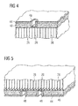
- a plurality of threaded bushings 48 are distributed over the floor panel 12, and embedded in the first and second surface layers 20, 22, particularly in the peripheral layer 44 and the intermediate layer 46. Similarly to the seat rail 42, each of the bushings 48 may, in an alternative, extend into the central layer 14. Each threaded bushing 48 penetrates the respective peripheral layer 44 and extends essentially perpendicularly to the first/second surface 14, 16. Threaded bushings 48 arranged at the first surface layer 20 as shown in Fig. 4 are provided for attaching to the floor panel interior components of the transportation means, e.g. aircraft monuments or the like, while threaded bushings 48 arranged at the second surface layer 22 as shown in Fig. 5 serve for mounting system components, such as electrical cables or liquid carrying lines, to the floor panel 12.
- the supporting structure 30 comprises four traverses 52. All traverses 52 are arranged in contact with the connecting device 32 at a side of the connecting device 32 opposite of the floor panel 12. In particular, each of the traverses 52 abuts against a surface of the first limb 34 of the connecting device 32 that is opposite of the surface of the first limb 34 facing the floor panel 12 and the second limb 36. Each of the traverses 52 is rigidly connected to the connecting device 32 and extends in a second direction Y that is perpendicular to the first direction X and, in the situation shown in figures 1 to 5 in which the floor panel 12 is in its mounted state, parallel to the central plane ZZ.
- the central plane ZZ crosses each of the traverses 52.
- the central plane ZZ merely extends in parallel to the second direction Y and the traverses 52.
- the traverses 52 are arranged offset relative to the floor panel 12 in the second direction Y, whereas, in a further alternative, at least one of the traverses 52 may be arranged such as to overlap a minor part of the floor panel 12.
- the floor assembly 10 comprises a plurality of struts 53 having an S-shaped cross section in a second plane that is parallel to the first and the second direction, X, Y. At its opposite ends 56, 58 in the first direction X, each strut 53 is rigidly fixed to two neighboring traverses 52, respectively, positioned on the same side of the floor panel 12 in the second direction Y.
- the supporting structure comprises a plurality of support rods 54 extending in a third direction Z which is perpendicular to the first and second direction X, Y, and, thus, when the floor panel is in its mounted state, also perpendicular to the central plane ZZ.
- each support rod 54 is fixed to and extends from the connecting device in the third direction Z.
- each support rod 54 is spaced apart from the floor panel 12.
- the dimensions of the central layer 14 as well as the first surface layer and the second surface layer 20, 22 are about 5 cm and 2.5 cm, respectively, in the third direction Z.
- the floor panel 12, in its mounted state shown in figures 1 to 5 is about 50 cm long in the first direction X and about 3 m wide in the second direction Y.
- a transportation means section 80 herein a section of an aircraft, comprises the floor assembly 10 and two structural parts 82 in the form of ribs of an aircraft fuselage extending in parallel to each other, and each having a substantially C-shaped cross section in a plane that is perpendicular to the first direction X.
- the length of the floor panel 12 in the first direction X essentially corresponds to the distance between the structural parts 82 in the first direction X.
- the length of the floor panel 12 in the first direction X is essentially n times the distance between the structural parts 82 in the first direction X, wherein n is a natural number larger than 0.
- the length of the floor panel 12 in the first direction X may, moreover, be at most the length of the transportation means section in the first direction X.
- the transportation means section 80 is essentially free of any cross-beams overlapping with the floor panel 12 when viewed in the third direction Z.
- the floor panel 12 when the floor panel 12 is in its mounted state, it is suspended to the structural parts 82 only by the supporting structure 30 and the connecting device 32.
Landscapes
- Engineering & Computer Science (AREA)
- Mechanical Engineering (AREA)
- Life Sciences & Earth Sciences (AREA)
- Wood Science & Technology (AREA)
- Aviation & Aerospace Engineering (AREA)
- Floor Finish (AREA)
Abstract
Description
- The present invention concerns a floor assembly for a transportation means, a transportation means section having the floor assembly, as well as a transportation means having the floor assembly and/or the transportation means section.
- Modern transportation means, such as aircraft or trains, may be configured for transporting freight and passengers at the same time. Therefore, space within transportation means available for transporting is typically divided into a passenger compartment and a freight/cargo hold by a cabin floor, to whose underside system components, such as electric cables and fluid guiding lines, can be mounted. Examples of aircraft cabin floors are described in
documents DE 10 2007 062 111 A1 andDE 10 2005 045 181 . - Typically, an aircraft cabin floor comprises of a plurality of floor panels, which are each attached to traverses, also referred to as cross-beams, extending below the floor panels transversally through the entire aircraft body, e.g. by means of a screw connection. In order to transmit load acting upon the floor panels due to the weight of the passengers and/or aircraft interior components to the aircraft structure, the cross-beams are rigidly fixed to one or more structural parts of the aircraft, such as to ribs and/or stringers, extending transversally or longitudinally relative to the aircraft fuselage longitudinal axis.
- The present invention is directed to the object to provide a floor assembly which is space-efficient and has a high stiffness. Furthermore, the invention is directed to the object to provide a transportation means section having such floor assembly, and a transportation means having the transportation means section and/or the floor assembly.
- This problem is solved by a floor assembly having the features of claim 1, a transportation means section according to claim 13, and a transportation means according to claim 15.
- The floor assembly is provided for a transportation means such as an aircraft or a train, and comprises a flat floor panel having a central layer through the entirety of which a central plane of the central layer extends. The central layer connects a first surface layer arranged on a first surface of the central layer and a second surface layer arranged on a second surface of the central layer. The cross-sectional area of the central layer in the central plane may be larger than any of the cross-sectional areas of the first and/or the second surface layer in a plane perpendicular to the central plane. Moreover, the floor assembly comprises a supporting structure adapted to be fixed to a structural part of the transportation means, and an elongate connecting device extending in a first direction. The connecting device is itself fixed to the supporting structure and is adapted for detachably mounting the floor panel to the supporting structure. When the floor panel is in its mounted state in which it is mounted to the supporting structure, the first direction is parallel to the central plane, and the connecting device stands in engagement with the central layer of the floor panel and abuts at least in sections against at least a portion of an outer lateral surface of the floor panel.
- Preferably, the connecting device has a substantially J-shaped / hook-shaped cross-section in a first plane that is perpendicular to the first direction. For example, the connecting device may comprise an extruded J-shaped profile, e.g., made of metal such as aluminum. In the mounted state, i.e. when the floor panel is mounted to the connecting device, the profile is aligned such that its short limb (hook-tip portion) is closer to the center of the floor panel than its long limb. In other words, the connecting device may comprise a first limb and a second limb which extends in parallel to the first limb. In this case, the first and the second limb are connected by a base part which extends perpendicularly to the first and the second limb. When the floor panel is in its mounted state, the first limb may abut against at least a portion of the outer lateral surface of the floor panel, and the second limb may engage into the central layer. The base portion may abut against the second surface of the central layer. Thereby, the floor panel, particularly the central layer thereof in its peripheral portion proximate to the outer lateral surface, is fixedly secured to the connecting device against displacement in parallel to the central plane. Optionally, a part of the peripheral portion may be clamped between the first and the second limb of the connecting device. Furthermore, it is conceivable that the connecting device, at least at its surfaces contacting the floor panel, is coated with a damping material, such as a rubber.
- In the floor panel, a groove may be formed preferably complementary to the second limb such as to form-fittingly receive the second limb. For example, the groove may be milled into the central layer. In particular, the groove may have a cross-section that is substantially U- or V-shaped and that extends from the second surface into the central layer, advantageously in the peripheral portion. Accordingly, the width of the base portion essentially corresponds to the distance between the outer lateral surface and the groove, and/or the depth of the groove is approximately the length of the second limb in a direction perpendicular to the central plane. Optionally, if a second surface layer is formed in the peripheral portion, the second surface layer may cover at least a portion of an inner surface of the groove. Moreover, it is conceivable that an elongate insert, e.g. made of a metal material such as aluminum, is fixed inside the groove such that its outer surface faces the inner surface of the groove. This insert preferably extends in parallel to the outer lateral surface, thus, in the groove in the first direction. Optionally, the insert may be rigidly fixed to the groove, e.g., to the inner surface thereof. If an insert is present, the inner surface thereof is formed such as to correspond with the second limb.
- In order to attach the floor panel to the connecting device, the floor panel is aligned such that a projection of the connecting device, particularly the second limb, is below the groove formed in the floor panel. Subsequently, the floor panel is pressed down such that the projection engages into the groove. To detach the floor panel from the connecting device, this process is inverted: The floor panel is lifted so that the projection disengages from the groove. Thus, the panel can be handled freely within the transportation means or transported out of the transportation means through a door.
- The central layer may have a honeycomb structured core with a plurality of cells delimited by parallel cell walls. Each of the cell walls may cross the central plane. For example, each of the cells may be formed such as to have a hexagonal basis or cross-section in the central plane. In particular, the honeycomb structured core may extend over the entire central layer of the floor panel, e.g., from the aforementioned outer lateral wall to another outer lateral wall on an opposite side of the floor panel. Each of the cells may be closed at the first and/or the second surface of the central layer by the first/second surface layer, which may be formed at least in sections integrally with the cell walls. The cell walls may be formed by a metal material such as aluminum. Additionally, it is conceivable that the cells are covered on the first and/or second surface by an additional cover layer made of the same material as the cell walls.
- Moreover, the floor assembly may comprise at least one seat rail which is arranged such as to penetrate through the first surface layer and into the central layer. The seat rail preferably extends in the first direction. For example, the seat rail may comprise a seat holding portion, which has a substantially C-shaped cross-section in a plane perpendicular to the first direction with its open surface facing away from the central plane, and an anchor portion attached to the seat holding portion at its surface opposite of the open surface. The latter surface may contact the first surface of the central layer without penetrating into the central layer, and the anchor portion may be arranged within the central layer. Moreover, the anchor portion may be fixed to the central layer, e.g., by an adhesive or press-fitting. If the seat rail does not penetrate into the central layer, but is embedded in the first surface layer, it preferably lacks an anchor portion.
- The first and/or the second surface layer may comprise a peripheral layer formed of a composite material and an intermediate layer formed of a foam material and arranged between the peripheral layer and the central layer. Accordingly, the peripheral layer is formed rigidly such as to prevent damage of the intermediate layer and/or the central layer, whereas the intermediate layer is more elastic than the peripheral layer such as to damp any impact on the floor panel. For example, the peripheral layer may be formed of a carbon fiber reinforced plastic material, whereas the intermediate layer may be formed of hard foam preferably admitted for aircraft production.
- In the first and/or in the second surface layer, one or more threaded bushings may be formed. These bushings extend essentially perpendicularly to the first and/or the second surface of the central layer through the peripheral layer, and optionally through the intermediate layer. Bushings on the first surface are provided for mounting transportation means interior components, e.g. aircraft monuments, whereas bushings on the second surface are provided for mounting system components, such as electric cables or hoses/lines for liquid supplies, to the floor assembly. Accordingly, the bushings have internal threads into which bolts for mounting the respective components may engage. Thus, the components may be simply and flexibly fixed to the floor assembly.
- The supporting structure may further comprise a plurality of traverses spaced apart from each other for fixing the floor assembly to the transportation means body. In particular, a first and a second traverse may be formed separate from the floor panel and rigidly fixed to the connecting device. Each of the traverses may extend from the connecting device in a second direction which is perpendicular to the first direction. When the floor panel is in its mounted state, the central plane of the central layer preferably extends in parallel to the second direction and the first traverse and the second traverse are arranged offset relative to the floor panel in the second direction. In other words, when viewed in a direction perpendicular to the central plane, the floor panel and each of the traverses are free of an overlap. Rather, in this view, at least a part of the connecting device, e.g. the first limb, is arranged between the floor panel and each traverse. Furthermore, it is conceivable that the space between two neighboring traverses is covered by detachable panels, such as panels for rapid decompression of an aircraft cabin.
- In a further embodiment, the floor assembly comprises a strut having an S-shaped cross-section in a second plane that is parallel to the first and the second direction. At its opposite ends in the first direction, the strut may be rigidly fixed to the first and to the second traverse, respectively. Thereby, longitudinal forces acting in the first direction on one of these traverses is effectively transmitted via the strut to the neighboring traverse. Moreover, the supporting structure may comprise a support rod extending in a third direction that may be perpendicular to the first and the second direction. The support rod may be fixed to the connecting device, particularly to the base part thereof, and may be adapted to be fixed to the structural part. When the floor panel is in its mounted state, the third direction is perpendicular to the central plane of the central layer, and the support rod is arranged offset relative to the floor panel in the third direction.
- The central layer of the floor panel may have a thickness of at least 4 cm, preferably at least 4.5 cm. The thickness may even be at least 5 cm to allow for improved stability. The first and/or the second surface layer may have a thickness of at most 1.5 cm, at most 2.5 cm or at most 3.5 cm. Preferably the thickness of at least one of these surface layers is about 2.5 cm. The peripheral layer may be substantially thinner than the intermediate layer. Moreover, the floor panel may have a length of at least 45 cm, and/or a width of at least 1.5 m. Preferably, the length of the floor panel is about 50 to 60 cm and the width of the floor panel is about 3 m. Thus, the floor assembly may extend in the second direction over the entire width of the transportation means in which the floor is to be arranged.
- In the present context, the terms length, width and thickness (of the floor panel) refer to the size in the first, second, and third direction, respectively, in the mounted state of the floor panel.
- A transportation means section, particularly an aircraft section or a train section, comprises at least one floor assembly described above in details, and a plurality of structural parts spaced apart in the first and/or the second direction. At least some of the structural parts are preferably ribs or stringers of the transportation means. Each structural part may have a curved, e.g. C-shaped, cross-section in a plane that is perpendicular to the first direction. The supporting structure is attached to each of the structural parts, and, when the floor panel is in its mounted state, the length of the floor panel in the first direction corresponds at least to the distance between two neighboring structural parts, e.g. neighboring ribs, in the first direction. Preferably, the connecting device comprises two portions arranged on opposite outer lateral surfaces of the floor panel. Each of these parts extends in the first direction from its associated first traverse to its associated second traverse, and is, thus, as long as the floor panel.
- The transportation means section may comprise further floor assemblies described above, which may be arranged adjacent to the above described floor assembly and have one or more of the features of the same. In particular, adjacent floor assemblies may be fixed to each other on end surfaces of their floor panels in and opposite of the first direction by means of tongue and groove connections. In any case, when the floor panel is in its mounted state, it is preferably suspended to the structural part only by the supporting structure and the connecting device. Thus, the floor assembly does not require cross-beams that run below the floor panels. Rather the combination of the hereinabove described components result in a self-supporting transportation means floor.
- A transportation means, particularly an aircraft or a train, comprises a transportation means section and/or a floor assembly as described hereinabove.
- Preferred embodiments of a floor assembly and a transportation means section are described in greater detail with reference to the attached schematic drawings in the following, wherein
- Figure 1
- shows a perspective view of a floor assembly in its mounted state as viewed in the first direction,
- Figure 2
- shows a detailed perspective view of an area A marked in
Fig. 1 in the region of an outer lateral surface of the floor panel, - Figure 3
- shows a detailed perspective view of an area B marked in
Fig. 1 in the region of a guiding rail of the floor assembly, - Figure 4
- shows a detailed perspective view of an area C marked in
Fig. 1 in the region of a bushing arranged on the first surface of the floor assembly, - Figure 5
- shows a detailed perspective view of an area D marked in
Fig. 1 in the region of a bushing arranged on the second surface of the floor assembly, and - Figure 6
- shows a perspective view of a transportation means section, wherein the floor assembly is in its mounted state, and the viewing direction is the first direction.
- A
floor assembly 10 for a transportation means is shown inFigs. 1 to 5 . The transportation means is exemplarily an aircraft. In the figures, a central region of thefloor assembly 10 is omitted. Moreover, in the following, only the half of thefloor assembly 10 shown inFig. 1 to the left will exemplarily be described. The right half of thefloor assembly 10 shown inFig. 1 is configured like the left half, but mirrored on an imaginary vertical plane extending through the center ofFig. 1 . - The
floor assembly 10 comprises afloor panel 12 having acentral layer 14 through which a central plane ZZ of thecentral layer 14 extends. Thecentral layer 14 comprises afirst surface 16 and asecond surface 18 on two opposite sides of thecentral layer 14. Each of thefirst surface 16 and thesecond surface 18 are parallel to the central plane ZZ. Afirst surface layer 20 covers a partial area of thefirst surface 16, and asecond surface layer 22 covers the same partial area of thesecond surface 18 of thecentral layer 14. Thus, thefirst surface layer 20 is formed on and in direct contact with the first surface, and thesecond surface layer 20 is formed on and in direct contact with thesecond surface 18, so that thecentral layer 14 interconnects the first and thesecond surface layer - A supporting
structure 30 is formed laterally in the proximity of thefloor panel 12 and provided for fixing thefloor panel 10 to a structural part (not shown) of the transportation means. To the supportingstructure 30, a connectingdevice 32 is fixed to enable detachably mounting thefloor panel 12 to the supportingstructure 30. - The connecting
device 32 extends in a first direction X and is formed as a J-profile which has a J-shaped or hook-shaped cross-section in a first plane (i.e., the plane of projection ofFig. 1 ) that is perpendicular to the first direction X. In particular, as shown more detailed inFig. 2 , the connectingdevice 32 comprises a first and asecond limb base part 38, which is aligned substantially perpendicularly to first andsecond limbs first limb 34, by which the connectingdevice 32 is attached to the supportingstructure 30, and which stands in direct contact therewith, extends farther from thebase part 38 than thesecond limb 36. The first andsecond limbs base part 38 are substantially flat and extend in the first direction X. In this example, the connectingdevice 32 is formed as an aluminum profile extruded in the first direction X. - In
Fig. 1 , thefloor panel 12 is shown in its mounted state in which it is mounted to the supportingstructure 30 by means of the connecting device. In this situation, the first direction X is parallel to the central plane ZZ, and a lateral end portion of thecentral layer 14 of thefloor panel 12 is tightly clamped between the first and thesecond limbs device 32. Particularly, thefirst limb 34 abuts against an outer lateral surface 24 of thefloor panel 12, and thesecond limb 36 penetrates through thesecond surface 18 into thecentral layer 14 over a substantial part of the length of the connectingdevice 32 in the first direction X (cf.Fig. 2 ). - As illustrated in
figures 2 to 5 , thecentral layer 14 has a honeycomb structured core with a plurality of cells delimited by substantiallyparallel cell walls 26, each crossing the central plane ZZ. Herein, eachcell wall 26 is aligned perpendicularly to the central plane ZZ. Accordingly, the honeycomb structure is configured to hinder compression of thefloor panel 12 perpendicularly to the central plane ZZ. The cells are preferably hexagonal such that each cell is delimited by six cell walls, whereby two neighboring cell walls are arranged at an angle of 120° relative to each other. Aninsert 40 that is formed complementary to thesecond limb 32 is positioned in a groove arranged in an area of the central layer proximate to the outer lateral surface 24 of thefloor panel 12. In this area, neither thefirst surface layer 20, nor thesecond surface layer 22 are formed. Yet, in an alternative, it is conceivable that thesecond surface layer 22 covers an inner surface of the groove. Both, theinsert 40 and the groove extend in parallel to the outer lateral surface 24 in the first direction X. Theinsert 40 is fixedly secured to thecentral layer 14 in the groove. - Furthermore, as shown in
figure 3 , aseat rail 42 is arranged such as to penetrate through thefirst surface layer 20 and into thecentral layer 14. Alternatively, it is conceivable that theseat rail 42 is at least partially embedded in thefirst surface layer 20 without penetrating into thecentral layer 14. In particular, theseat rail 42 may be in contact with thefirst surface 16 of thecentral layer 14 such as to cover some of the cells at the first surface of the central layer. In this case, loads acting vertically on a seat mounted to theseat rail 42 are directly transmitted to the central layer, so that wear of the first surface layer is reduced. - Both, the first and the second surface layers 20, 22, comprise a
peripheral layer 44 and anintermediate layer 46, wherein theintermediate layer 46 is arranged between theperipheral layer 44 and thecentral layer 14, such as to connect theperipheral layer 44 and theintermediate layer 46. The peripheral layer is formed of a composite material, e.g. fibre reinforced plastics such as carbon-fibre reinforced plastics or glass-fibre reinforced plastics, and the intermediate layer is formed of a hard foam material, such as hard foam admitted for aircraft. Thus, theperipheral layer 44 is formed more rigid than theintermediate layer 46 such as to prevent damage of the underlying intermediate andcentral layers intermediate layer 46 is rather more elastic than theperipheral layer 42 in order to damp any impulses, e.g., of passengers walking on the floor panels. - Spaced apart from the
seat rail 42, a plurality of threadedbushings 48 are distributed over thefloor panel 12, and embedded in the first and second surface layers 20, 22, particularly in theperipheral layer 44 and theintermediate layer 46. Similarly to theseat rail 42, each of thebushings 48 may, in an alternative, extend into thecentral layer 14. Each threadedbushing 48 penetrates the respectiveperipheral layer 44 and extends essentially perpendicularly to the first/second surface bushings 48 arranged at thefirst surface layer 20 as shown inFig. 4 are provided for attaching to the floor panel interior components of the transportation means, e.g. aircraft monuments or the like, while threadedbushings 48 arranged at thesecond surface layer 22 as shown inFig. 5 serve for mounting system components, such as electrical cables or liquid carrying lines, to thefloor panel 12. - Referring back to
figure 1 , the supportingstructure 30 comprises four traverses 52. All traverses 52 are arranged in contact with the connectingdevice 32 at a side of the connectingdevice 32 opposite of thefloor panel 12. In particular, each of thetraverses 52 abuts against a surface of thefirst limb 34 of the connectingdevice 32 that is opposite of the surface of thefirst limb 34 facing thefloor panel 12 and thesecond limb 36. Each of thetraverses 52 is rigidly connected to the connectingdevice 32 and extends in a second direction Y that is perpendicular to the first direction X and, in the situation shown infigures 1 to 5 in which thefloor panel 12 is in its mounted state, parallel to the central plane ZZ. Herein, the central plane ZZ crosses each of thetraverses 52. However, it is conceivable that the central plane ZZ merely extends in parallel to the second direction Y and thetraverses 52. Moreover, thetraverses 52 are arranged offset relative to thefloor panel 12 in the second direction Y, whereas, in a further alternative, at least one of thetraverses 52 may be arranged such as to overlap a minor part of thefloor panel 12. - Moreover, the
floor assembly 10 comprises a plurality ofstruts 53 having an S-shaped cross section in a second plane that is parallel to the first and the second direction, X, Y. At its opposite ends 56, 58 in the first direction X, eachstrut 53 is rigidly fixed to twoneighboring traverses 52, respectively, positioned on the same side of thefloor panel 12 in the second direction Y. - For additional stability, the supporting structure comprises a plurality of
support rods 54 extending in a third direction Z which is perpendicular to the first and second direction X, Y, and, thus, when the floor panel is in its mounted state, also perpendicular to the central plane ZZ. In particular, eachsupport rod 54 is fixed to and extends from the connecting device in the third direction Z. Furthermore, eachsupport rod 54 is spaced apart from thefloor panel 12. - The dimensions of the
central layer 14 as well as the first surface layer and thesecond surface layer floor panel 12, in its mounted state shown infigures 1 to 5 , is about 50 cm long in the first direction X and about 3 m wide in the second direction Y. - A transportation means
section 80, herein a section of an aircraft, comprises thefloor assembly 10 and twostructural parts 82 in the form of ribs of an aircraft fuselage extending in parallel to each other, and each having a substantially C-shaped cross section in a plane that is perpendicular to the first direction X. In the mounted state, the length of thefloor panel 12 in the first direction X essentially corresponds to the distance between thestructural parts 82 in the first direction X. In an alternative, in the same situation, the length of thefloor panel 12 in the first direction X is essentially n times the distance between thestructural parts 82 in the first direction X, wherein n is a natural number larger than 0. The length of thefloor panel 12 in the first direction X may, moreover, be at most the length of the transportation means section in the first direction X. - As shown in
figure 6 , the transportation meanssection 80 is essentially free of any cross-beams overlapping with thefloor panel 12 when viewed in the third direction Z. In other words, when thefloor panel 12 is in its mounted state, it is suspended to thestructural parts 82 only by the supportingstructure 30 and the connectingdevice 32.
Claims (15)
- A floor assembly (10) for a transportation means, comprising:- a flat floor panel (12) having a central layer (14) through the entirety of which a central plane (ZZ) of the central layer (14) extends, which central layer (14) connects a first surface layer (20) arranged on a first surface (16) of the central layer (14) with a second surface layer (22) arranged on a second surface (18) of the central layer (14);- a supporting structure (30) adapted to be fixed to one or more structural parts of the transportation means; and- an elongate connecting device (32) extending in a first direction (X), which connecting device (32) is fixed to the supporting structure (30) and adapted for detachably mounting the floor panel (12) to the supporting structure (30),wherein, when the floor panel (12) is in its mounted state in which it is mounted to the supporting structure (30), the first direction (X) is parallel to the central plane (ZZ) and the connecting device (32) stands in engagement with the central layer (14) of the floor panel (12) and abuts at least in sections against an outer lateral surface of the floor panel (12).
- The floor assembly according to claim 1, wherein the connecting device (32) has at least in sections a substantially J-shaped cross-section in a first plane that is perpendicular to the first direction (X).
- The floor assembly according to one of the preceding claims,
wherein the connecting device (32) comprises a first limb (34) and a second limb (36) extending in parallel to the first limb (34), the first and the second limb (36) being connected by a base part (38) which extends perpendicularly to the first and the second limb (36),
wherein, when the floor panel (12) is in its mounted state, the first limb (34) abuts against at least a portion of the outer lateral surface of the floor panel (12), and the second limb (36) engages into the central layer (14). - The floor assembly according to one of the preceding claims,
wherein the central layer (14) has a honeycomb structured core having a plurality of cells delimited by parallel cell walls (26), each of the cell walls (26) crossing the central plane (ZZ),
wherein an elongate insert (40) is positioned in an elongate groove extending through the second surface into the central layer (14), which insert (40) extends in parallel to the outer lateral surface. - The floor assembly according to one of the preceding claims, further comprising a seat rail (42) which is arranged such as to penetrate through the first surface layer (20) and into the central layer (14).
- The floor assembly according to one of the preceding claims, wherein the first and/or the second surface layer comprises a peripheral layer (44) formed of a composite material and an intermediate layer (46) formed of a foam material and arranged between the peripheral layer (44) and the central layer (14).
- The floor assembly according to one of the preceding claims, wherein one or more threaded bushings (48) are formed in the first and/or in the second surface layer (20, 22), wherein each of the threaded bushings (48) extends essentially perpendicularly to the first and/or the second surface of the central layer (14).
- The floor assembly according to one of the preceding claims,
wherein the supporting structure (30) comprises a first traverse and a second traverse, each formed separate from the floor panel (12), rigidly fixed to the connecting device (32), and extending in a second direction (Y) which is perpendicular to the first direction (X),
wherein, when the floor panel (12) is in its mounted state, the central plane (ZZ) of the central layer (14) extends in parallel to the second direction (Y) and the first traverse and the second traverse are arranged offset relative to the floor panel (12) in the second direction (Y). - The floor assembly according to claim 8, further comprising a strut (53) having an S-shaped cross-section in a second plane that is parallel to the first and the second direction (X, Y), wherein, at its opposite ends in the first direction (X), the strut (53) is rigidly fixed to the first and to the second traverse, respectively.
- The floor assembly according to one of the preceding claims,
wherein the supporting structure (30) comprises at least one support rod (54) extending in a third direction (Z), which support rod is fixed to the connecting device (32) and adapted to be fixed to the structural part, and
wherein, when the floor panel (12) is in its mounted state, the third direction is perpendicular to the central plane (ZZ) of the central layer (14), and the support rod is arranged offset relative to the floor panel (12) in the third direction. - The floor assembly according to one of the preceding claims, wherein the central layer (14) of the floor panel (12) has a thickness of at least 4.5 cm, and/or wherein the first surface layer (20) and/or the second surface layer (22) have a thickness of at most 3 cm.
- The floor assembly according to one of the preceding claims, wherein the floor panel (12), in its mounted state, has a length in the first direction (X) of at least 45 cm, and/or a width in the second direction (Y) of at least 1.5 m.
- A transportation means section (80), particularly an aircraft section or a train section, comprising:- a floor assembly (10) according to one of the preceding claims; and- a plurality of structural parts spaced apart relative to each other in the first direction (X),wherein each structural part has a curved cross-section in a plane that is perpendicular to the first direction (X),
wherein the supporting structure (30) is attached to each of the structural parts, and
wherein, when the floor panel (12) is in its mounted state, the length of the floor panel (12) in the first direction (X) corresponds at least to the distance between two neighboring structural parts in the first direction (X). - The transportation means section according to claim 13, wherein, when the floor panel (12) is in its mounted state, it is suspended to the structural part only by the supporting structure (30) and the connecting device (32).
- A transportation means, particularly an aircraft or a train, comprising a transportation means section (80) according to claim 13 or 14 and/or a floor assembly (10) according to one of claims 1 to 12.
Priority Applications (1)
| Application Number | Priority Date | Filing Date | Title |
|---|---|---|---|
| EP16180376.2A EP3272645B1 (en) | 2016-07-20 | 2016-07-20 | Floor assembly for a transportation means, transportation means section, and transportation means |
Applications Claiming Priority (1)
| Application Number | Priority Date | Filing Date | Title |
|---|---|---|---|
| EP16180376.2A EP3272645B1 (en) | 2016-07-20 | 2016-07-20 | Floor assembly for a transportation means, transportation means section, and transportation means |
Publications (2)
| Publication Number | Publication Date |
|---|---|
| EP3272645A1 true EP3272645A1 (en) | 2018-01-24 |
| EP3272645B1 EP3272645B1 (en) | 2018-09-19 |
Family
ID=56507431
Family Applications (1)
| Application Number | Title | Priority Date | Filing Date |
|---|---|---|---|
| EP16180376.2A Active EP3272645B1 (en) | 2016-07-20 | 2016-07-20 | Floor assembly for a transportation means, transportation means section, and transportation means |
Country Status (1)
| Country | Link |
|---|---|
| EP (1) | EP3272645B1 (en) |
Cited By (1)
| Publication number | Priority date | Publication date | Assignee | Title |
|---|---|---|---|---|
| FR3106568A1 (en) * | 2020-01-24 | 2021-07-30 | Airbus Operations (S.A.S.) | A method of assembling an aircraft comprising a step of mounting at least one operating panel forming at least one floor prior to a step of mounting equipment |
Citations (5)
| Publication number | Priority date | Publication date | Assignee | Title |
|---|---|---|---|---|
| FR2617785A1 (en) * | 1987-07-10 | 1989-01-13 | Alsthom | Railway carriage body |
| DE102005045181A1 (en) | 2005-09-21 | 2007-04-05 | Eads Deutschland Gmbh | Floor structure for aircraft |
| DE102007062111A1 (en) | 2007-12-21 | 2009-07-02 | Airbus Deutschland Gmbh | Shielding arrangement for lightning protection of e.g. electrical conductor, in aircraft, has installation space protectively arranged in region of floor framework, and delimitation surface provided with electrical conducting shield |
| FR2957050A1 (en) * | 2010-03-04 | 2011-09-09 | Eads Europ Aeronautic Defence | Fuselage structure for aircraft, has hull structure integrating internal reinforcement element that is extended on entire length transversal to longitudinal axis, and fixation rail fixing movable elements with consoles |
| WO2013074082A1 (en) * | 2011-11-15 | 2013-05-23 | The Boeing Company | Split joint assembly for modules used on mobile platforms |
-
2016
- 2016-07-20 EP EP16180376.2A patent/EP3272645B1/en active Active
Patent Citations (5)
| Publication number | Priority date | Publication date | Assignee | Title |
|---|---|---|---|---|
| FR2617785A1 (en) * | 1987-07-10 | 1989-01-13 | Alsthom | Railway carriage body |
| DE102005045181A1 (en) | 2005-09-21 | 2007-04-05 | Eads Deutschland Gmbh | Floor structure for aircraft |
| DE102007062111A1 (en) | 2007-12-21 | 2009-07-02 | Airbus Deutschland Gmbh | Shielding arrangement for lightning protection of e.g. electrical conductor, in aircraft, has installation space protectively arranged in region of floor framework, and delimitation surface provided with electrical conducting shield |
| FR2957050A1 (en) * | 2010-03-04 | 2011-09-09 | Eads Europ Aeronautic Defence | Fuselage structure for aircraft, has hull structure integrating internal reinforcement element that is extended on entire length transversal to longitudinal axis, and fixation rail fixing movable elements with consoles |
| WO2013074082A1 (en) * | 2011-11-15 | 2013-05-23 | The Boeing Company | Split joint assembly for modules used on mobile platforms |
Cited By (1)
| Publication number | Priority date | Publication date | Assignee | Title |
|---|---|---|---|---|
| FR3106568A1 (en) * | 2020-01-24 | 2021-07-30 | Airbus Operations (S.A.S.) | A method of assembling an aircraft comprising a step of mounting at least one operating panel forming at least one floor prior to a step of mounting equipment |
Also Published As
| Publication number | Publication date |
|---|---|
| EP3272645B1 (en) | 2018-09-19 |
Similar Documents
| Publication | Publication Date | Title |
|---|---|---|
| US9586671B2 (en) | Unitary panel for the floor of a vehicle, floor, and vehicle including such a unitary panel | |
| US8544794B2 (en) | Floor panel and installation for fixing layout elements comprising such panels | |
| CN101421155B (en) | Aircraft floor, use of said floor and aircraft section fitted with said floor | |
| RU2576647C2 (en) | Aircraft structural assembly | |
| EP2179920B1 (en) | Aircraft cabin floor structures, systems and methods | |
| US11401023B2 (en) | Aircraft cargo floor architecture and method of modifying the aircraft cargo floor architecture | |
| US9139282B2 (en) | Fastening arrangement for attaching a floor | |
| US20060038071A1 (en) | Flush-top seat mounting rail for passenger aircraft | |
| US10906628B2 (en) | Box structural arrangement for an aircraft and manufacturing method thereof | |
| US8240606B2 (en) | Integrated aircraft floor with longitudinal beams | |
| RU2509680C1 (en) | Assy of interaction of stresses, particularly, assy of interaction of loads for aircraft reclined door | |
| WO2010108775A4 (en) | Assembly-ready structures | |
| CN104507806A (en) | Aircraft three-dimensional space integrated attachment device | |
| US10773784B2 (en) | Floor module of an aircraft cargo hold | |
| US20190112035A1 (en) | Landing gear bay roof comprising at least one gantry installed against a lower face of its wall | |
| JP2009509840A5 (en) | ||
| US8100360B2 (en) | Light rail system for powered introduction of large loads in a structure | |
| EP3081487A1 (en) | Monument for a cabin of a vehicle, and fastening arrangement | |
| CA2930134A1 (en) | A pressure bulkhead for an aircraft fuselage, and an aircraft comprising such a pressure bulkhead | |
| US9051051B1 (en) | Floating aircraft archway and method therefor | |
| US8636256B2 (en) | Curtain support assembly, in a framework design, in a cabin of a vehicle | |
| EP2825449B1 (en) | Aircraft fuselage structure comprising transverse profiles and framework structure | |
| EP3272645B1 (en) | Floor assembly for a transportation means, transportation means section, and transportation means | |
| US20240174341A1 (en) | Floor system for a cabin of a vehicle with form-fitting floor panel connection | |
| CN103387046B (en) | Do not use method and the airborne vehicle that can connect composite material structure through the securing member of composite material structure |
Legal Events
| Date | Code | Title | Description |
|---|---|---|---|
| PUAI | Public reference made under article 153(3) epc to a published international application that has entered the european phase |
Free format text: ORIGINAL CODE: 0009012 |
|
| STAA | Information on the status of an ep patent application or granted ep patent |
Free format text: STATUS: REQUEST FOR EXAMINATION WAS MADE |
|
| 17P | Request for examination filed |
Effective date: 20170502 |
|
| AK | Designated contracting states |
Kind code of ref document: A1 Designated state(s): AL AT BE BG CH CY CZ DE DK EE ES FI FR GB GR HR HU IE IS IT LI LT LU LV MC MK MT NL NO PL PT RO RS SE SI SK SM TR |
|
| AX | Request for extension of the european patent |
Extension state: BA ME |
|
| GRAP | Despatch of communication of intention to grant a patent |
Free format text: ORIGINAL CODE: EPIDOSNIGR1 |
|
| STAA | Information on the status of an ep patent application or granted ep patent |
Free format text: STATUS: GRANT OF PATENT IS INTENDED |
|
| RIC1 | Information provided on ipc code assigned before grant |
Ipc: B64D 17/10 20060101ALI20180219BHEP Ipc: B64C 1/18 20060101AFI20180219BHEP Ipc: B61D 17/10 20060101ALI20180219BHEP Ipc: B62D 25/20 20060101ALI20180219BHEP |
|
| INTG | Intention to grant announced |
Effective date: 20180322 |
|
| GRAS | Grant fee paid |
Free format text: ORIGINAL CODE: EPIDOSNIGR3 |
|
| GRAA | (expected) grant |
Free format text: ORIGINAL CODE: 0009210 |
|
| STAA | Information on the status of an ep patent application or granted ep patent |
Free format text: STATUS: THE PATENT HAS BEEN GRANTED |
|
| AK | Designated contracting states |
Kind code of ref document: B1 Designated state(s): AL AT BE BG CH CY CZ DE DK EE ES FI FR GB GR HR HU IE IS IT LI LT LU LV MC MK MT NL NO PL PT RO RS SE SI SK SM TR |
|
| REG | Reference to a national code |
Ref country code: GB Ref legal event code: FG4D |
|
| REG | Reference to a national code |
Ref country code: CH Ref legal event code: EP |
|
| REG | Reference to a national code |
Ref country code: AT Ref legal event code: REF Ref document number: 1042946 Country of ref document: AT Kind code of ref document: T Effective date: 20181015 |
|
| REG | Reference to a national code |
Ref country code: IE Ref legal event code: FG4D |
|
| REG | Reference to a national code |
Ref country code: DE Ref legal event code: R096 Ref document number: 602016005683 Country of ref document: DE |
|
| REG | Reference to a national code |
Ref country code: NL Ref legal event code: MP Effective date: 20180919 |
|
| PG25 | Lapsed in a contracting state [announced via postgrant information from national office to epo] |
Ref country code: NO Free format text: LAPSE BECAUSE OF FAILURE TO SUBMIT A TRANSLATION OF THE DESCRIPTION OR TO PAY THE FEE WITHIN THE PRESCRIBED TIME-LIMIT Effective date: 20181219 Ref country code: LT Free format text: LAPSE BECAUSE OF FAILURE TO SUBMIT A TRANSLATION OF THE DESCRIPTION OR TO PAY THE FEE WITHIN THE PRESCRIBED TIME-LIMIT Effective date: 20180919 Ref country code: BG Free format text: LAPSE BECAUSE OF FAILURE TO SUBMIT A TRANSLATION OF THE DESCRIPTION OR TO PAY THE FEE WITHIN THE PRESCRIBED TIME-LIMIT Effective date: 20181219 Ref country code: FI Free format text: LAPSE BECAUSE OF FAILURE TO SUBMIT A TRANSLATION OF THE DESCRIPTION OR TO PAY THE FEE WITHIN THE PRESCRIBED TIME-LIMIT Effective date: 20180919 Ref country code: GR Free format text: LAPSE BECAUSE OF FAILURE TO SUBMIT A TRANSLATION OF THE DESCRIPTION OR TO PAY THE FEE WITHIN THE PRESCRIBED TIME-LIMIT Effective date: 20181220 Ref country code: RS Free format text: LAPSE BECAUSE OF FAILURE TO SUBMIT A TRANSLATION OF THE DESCRIPTION OR TO PAY THE FEE WITHIN THE PRESCRIBED TIME-LIMIT Effective date: 20180919 Ref country code: SE Free format text: LAPSE BECAUSE OF FAILURE TO SUBMIT A TRANSLATION OF THE DESCRIPTION OR TO PAY THE FEE WITHIN THE PRESCRIBED TIME-LIMIT Effective date: 20180919 |
|
| REG | Reference to a national code |
Ref country code: LT Ref legal event code: MG4D |
|
| PG25 | Lapsed in a contracting state [announced via postgrant information from national office to epo] |
Ref country code: AL Free format text: LAPSE BECAUSE OF FAILURE TO SUBMIT A TRANSLATION OF THE DESCRIPTION OR TO PAY THE FEE WITHIN THE PRESCRIBED TIME-LIMIT Effective date: 20180919 Ref country code: LV Free format text: LAPSE BECAUSE OF FAILURE TO SUBMIT A TRANSLATION OF THE DESCRIPTION OR TO PAY THE FEE WITHIN THE PRESCRIBED TIME-LIMIT Effective date: 20180919 Ref country code: HR Free format text: LAPSE BECAUSE OF FAILURE TO SUBMIT A TRANSLATION OF THE DESCRIPTION OR TO PAY THE FEE WITHIN THE PRESCRIBED TIME-LIMIT Effective date: 20180919 |
|
| REG | Reference to a national code |
Ref country code: AT Ref legal event code: MK05 Ref document number: 1042946 Country of ref document: AT Kind code of ref document: T Effective date: 20180919 |
|
| PG25 | Lapsed in a contracting state [announced via postgrant information from national office to epo] |
Ref country code: AT Free format text: LAPSE BECAUSE OF FAILURE TO SUBMIT A TRANSLATION OF THE DESCRIPTION OR TO PAY THE FEE WITHIN THE PRESCRIBED TIME-LIMIT Effective date: 20180919 Ref country code: PL Free format text: LAPSE BECAUSE OF FAILURE TO SUBMIT A TRANSLATION OF THE DESCRIPTION OR TO PAY THE FEE WITHIN THE PRESCRIBED TIME-LIMIT Effective date: 20180919 Ref country code: EE Free format text: LAPSE BECAUSE OF FAILURE TO SUBMIT A TRANSLATION OF THE DESCRIPTION OR TO PAY THE FEE WITHIN THE PRESCRIBED TIME-LIMIT Effective date: 20180919 Ref country code: IT Free format text: LAPSE BECAUSE OF FAILURE TO SUBMIT A TRANSLATION OF THE DESCRIPTION OR TO PAY THE FEE WITHIN THE PRESCRIBED TIME-LIMIT Effective date: 20180919 Ref country code: IS Free format text: LAPSE BECAUSE OF FAILURE TO SUBMIT A TRANSLATION OF THE DESCRIPTION OR TO PAY THE FEE WITHIN THE PRESCRIBED TIME-LIMIT Effective date: 20190119 Ref country code: RO Free format text: LAPSE BECAUSE OF FAILURE TO SUBMIT A TRANSLATION OF THE DESCRIPTION OR TO PAY THE FEE WITHIN THE PRESCRIBED TIME-LIMIT Effective date: 20180919 Ref country code: CZ Free format text: LAPSE BECAUSE OF FAILURE TO SUBMIT A TRANSLATION OF THE DESCRIPTION OR TO PAY THE FEE WITHIN THE PRESCRIBED TIME-LIMIT Effective date: 20180919 Ref country code: ES Free format text: LAPSE BECAUSE OF FAILURE TO SUBMIT A TRANSLATION OF THE DESCRIPTION OR TO PAY THE FEE WITHIN THE PRESCRIBED TIME-LIMIT Effective date: 20180919 Ref country code: NL Free format text: LAPSE BECAUSE OF FAILURE TO SUBMIT A TRANSLATION OF THE DESCRIPTION OR TO PAY THE FEE WITHIN THE PRESCRIBED TIME-LIMIT Effective date: 20180919 |
|
| PG25 | Lapsed in a contracting state [announced via postgrant information from national office to epo] |
Ref country code: SK Free format text: LAPSE BECAUSE OF FAILURE TO SUBMIT A TRANSLATION OF THE DESCRIPTION OR TO PAY THE FEE WITHIN THE PRESCRIBED TIME-LIMIT Effective date: 20180919 Ref country code: PT Free format text: LAPSE BECAUSE OF FAILURE TO SUBMIT A TRANSLATION OF THE DESCRIPTION OR TO PAY THE FEE WITHIN THE PRESCRIBED TIME-LIMIT Effective date: 20190119 Ref country code: SM Free format text: LAPSE BECAUSE OF FAILURE TO SUBMIT A TRANSLATION OF THE DESCRIPTION OR TO PAY THE FEE WITHIN THE PRESCRIBED TIME-LIMIT Effective date: 20180919 |
|
| REG | Reference to a national code |
Ref country code: DE Ref legal event code: R097 Ref document number: 602016005683 Country of ref document: DE |
|
| PLBE | No opposition filed within time limit |
Free format text: ORIGINAL CODE: 0009261 |
|
| STAA | Information on the status of an ep patent application or granted ep patent |
Free format text: STATUS: NO OPPOSITION FILED WITHIN TIME LIMIT |
|
| PG25 | Lapsed in a contracting state [announced via postgrant information from national office to epo] |
Ref country code: DK Free format text: LAPSE BECAUSE OF FAILURE TO SUBMIT A TRANSLATION OF THE DESCRIPTION OR TO PAY THE FEE WITHIN THE PRESCRIBED TIME-LIMIT Effective date: 20180919 |
|
| 26N | No opposition filed |
Effective date: 20190620 |
|
| PG25 | Lapsed in a contracting state [announced via postgrant information from national office to epo] |
Ref country code: MC Free format text: LAPSE BECAUSE OF FAILURE TO SUBMIT A TRANSLATION OF THE DESCRIPTION OR TO PAY THE FEE WITHIN THE PRESCRIBED TIME-LIMIT Effective date: 20180919 |
|
| REG | Reference to a national code |
Ref country code: CH Ref legal event code: PL |
|
| PG25 | Lapsed in a contracting state [announced via postgrant information from national office to epo] |
Ref country code: TR Free format text: LAPSE BECAUSE OF FAILURE TO SUBMIT A TRANSLATION OF THE DESCRIPTION OR TO PAY THE FEE WITHIN THE PRESCRIBED TIME-LIMIT Effective date: 20180919 |
|
| REG | Reference to a national code |
Ref country code: BE Ref legal event code: MM Effective date: 20190731 |
|
| PG25 | Lapsed in a contracting state [announced via postgrant information from national office to epo] |
Ref country code: LU Free format text: LAPSE BECAUSE OF NON-PAYMENT OF DUE FEES Effective date: 20190720 Ref country code: LI Free format text: LAPSE BECAUSE OF NON-PAYMENT OF DUE FEES Effective date: 20190731 Ref country code: CH Free format text: LAPSE BECAUSE OF NON-PAYMENT OF DUE FEES Effective date: 20190731 Ref country code: BE Free format text: LAPSE BECAUSE OF NON-PAYMENT OF DUE FEES Effective date: 20190731 |
|
| PG25 | Lapsed in a contracting state [announced via postgrant information from national office to epo] |
Ref country code: IE Free format text: LAPSE BECAUSE OF NON-PAYMENT OF DUE FEES Effective date: 20190720 |
|
| GBPC | Gb: european patent ceased through non-payment of renewal fee |
Effective date: 20200720 |
|
| PG25 | Lapsed in a contracting state [announced via postgrant information from national office to epo] |
Ref country code: GB Free format text: LAPSE BECAUSE OF NON-PAYMENT OF DUE FEES Effective date: 20200720 |
|
| PG25 | Lapsed in a contracting state [announced via postgrant information from national office to epo] |
Ref country code: CY Free format text: LAPSE BECAUSE OF FAILURE TO SUBMIT A TRANSLATION OF THE DESCRIPTION OR TO PAY THE FEE WITHIN THE PRESCRIBED TIME-LIMIT Effective date: 20180919 |
|
| PG25 | Lapsed in a contracting state [announced via postgrant information from national office to epo] |
Ref country code: MT Free format text: LAPSE BECAUSE OF FAILURE TO SUBMIT A TRANSLATION OF THE DESCRIPTION OR TO PAY THE FEE WITHIN THE PRESCRIBED TIME-LIMIT Effective date: 20180919 Ref country code: HU Free format text: LAPSE BECAUSE OF FAILURE TO SUBMIT A TRANSLATION OF THE DESCRIPTION OR TO PAY THE FEE WITHIN THE PRESCRIBED TIME-LIMIT; INVALID AB INITIO Effective date: 20160720 |
|
| PG25 | Lapsed in a contracting state [announced via postgrant information from national office to epo] |
Ref country code: SI Free format text: LAPSE BECAUSE OF FAILURE TO SUBMIT A TRANSLATION OF THE DESCRIPTION OR TO PAY THE FEE WITHIN THE PRESCRIBED TIME-LIMIT Effective date: 20180919 |
|
| PG25 | Lapsed in a contracting state [announced via postgrant information from national office to epo] |
Ref country code: MK Free format text: LAPSE BECAUSE OF FAILURE TO SUBMIT A TRANSLATION OF THE DESCRIPTION OR TO PAY THE FEE WITHIN THE PRESCRIBED TIME-LIMIT Effective date: 20180919 |
|
| PGFP | Annual fee paid to national office [announced via postgrant information from national office to epo] |
Ref country code: DE Payment date: 20250722 Year of fee payment: 10 |
|
| PGFP | Annual fee paid to national office [announced via postgrant information from national office to epo] |
Ref country code: FR Payment date: 20250725 Year of fee payment: 10 |