EP3272307B1 - Workpiece unit and method for producing same - Google Patents
Workpiece unit and method for producing same Download PDFInfo
- Publication number
- EP3272307B1 EP3272307B1 EP16765117.3A EP16765117A EP3272307B1 EP 3272307 B1 EP3272307 B1 EP 3272307B1 EP 16765117 A EP16765117 A EP 16765117A EP 3272307 B1 EP3272307 B1 EP 3272307B1
- Authority
- EP
- European Patent Office
- Prior art keywords
- holding member
- workpiece
- workpiece body
- positioning portion
- unit according
- Prior art date
- Legal status (The legal status is an assumption and is not a legal conclusion. Google has not performed a legal analysis and makes no representation as to the accuracy of the status listed.)
- Active
Links
Images


Classifications
-
- A—HUMAN NECESSITIES
- A61—MEDICAL OR VETERINARY SCIENCE; HYGIENE
- A61C—DENTISTRY; APPARATUS OR METHODS FOR ORAL OR DENTAL HYGIENE
- A61C13/00—Dental prostheses; Making same
- A61C13/0003—Making bridge-work, inlays, implants or the like
- A61C13/0004—Computer-assisted sizing or machining of dental prostheses
-
- A—HUMAN NECESSITIES
- A61—MEDICAL OR VETERINARY SCIENCE; HYGIENE
- A61C—DENTISTRY; APPARATUS OR METHODS FOR ORAL OR DENTAL HYGIENE
- A61C13/00—Dental prostheses; Making same
- A61C13/0003—Making bridge-work, inlays, implants or the like
- A61C13/0022—Blanks or green, unfinished dental restoration parts
-
- A—HUMAN NECESSITIES
- A61—MEDICAL OR VETERINARY SCIENCE; HYGIENE
- A61C—DENTISTRY; APPARATUS OR METHODS FOR ORAL OR DENTAL HYGIENE
- A61C13/00—Dental prostheses; Making same
- A61C13/08—Artificial teeth; Making same
- A61C13/083—Porcelain or ceramic teeth
-
- A—HUMAN NECESSITIES
- A61—MEDICAL OR VETERINARY SCIENCE; HYGIENE
- A61C—DENTISTRY; APPARATUS OR METHODS FOR ORAL OR DENTAL HYGIENE
- A61C13/00—Dental prostheses; Making same
- A61C13/08—Artificial teeth; Making same
- A61C13/087—Artificial resin teeth
-
- A—HUMAN NECESSITIES
- A61—MEDICAL OR VETERINARY SCIENCE; HYGIENE
- A61C—DENTISTRY; APPARATUS OR METHODS FOR ORAL OR DENTAL HYGIENE
- A61C5/00—Filling or capping teeth
- A61C5/70—Tooth crowns; Making thereof
- A61C5/77—Methods or devices for making crowns
-
- A—HUMAN NECESSITIES
- A61—MEDICAL OR VETERINARY SCIENCE; HYGIENE
- A61C—DENTISTRY; APPARATUS OR METHODS FOR ORAL OR DENTAL HYGIENE
- A61C7/00—Orthodontics, i.e. obtaining or maintaining the desired position of teeth, e.g. by straightening, evening, regulating, separating, or by correcting malocclusions
- A61C7/12—Brackets; Arch wires; Combinations thereof; Accessories therefor
- A61C7/14—Brackets; Fixing brackets to teeth
-
- A—HUMAN NECESSITIES
- A61—MEDICAL OR VETERINARY SCIENCE; HYGIENE
- A61C—DENTISTRY; APPARATUS OR METHODS FOR ORAL OR DENTAL HYGIENE
- A61C8/00—Means to be fixed to the jaw-bone for consolidating natural teeth or for fixing dental prostheses thereon; Dental implants; Implanting tools
Definitions
- the present invention relates to a workpiece unit which comprises a workpiece body to be machined and a producing method thereof.
- a machining process is carried out while holding end portions of a workpiece unit.
- the workpiece body is also referred to as "blank”.
- blade For example, in the dental art field, an outer edge region of zirconia having a circular plate (disk) shape as the workpiece body is held by a machining apparatus and cutting out of a prosthesis is carried out.
- a ring is attached onto an outer edge of the blank with an adhesive agent so that the ring is fixed onto a chuck of the machining apparatus, whereby the blank is fixed onto the machining apparatus.
- a holding member (ring) is attached onto a smooth circumferential portion on a workpiece body (blank) via adhesive material.
- a position of the holding member is sometimes displaced from the predetermined position. If the holding member is not attached onto the workpiece body at the predetermined position, the position of the workpiece body relative to the machining apparatus would be displaced. Therefore, there is a case where the workpiece body may not be machined into a pre-designed shape.
- the holding member may be attached onto the workpiece body at a pertinent position, the position of the holding member relative to the workpiece body is sometimes displaced due to environment or load during machining, transportation, storage and the like. In such case, a problem would occur like as above.
- the holding member may be attached onto the workpiece body at a pertinent position and that shifting or displacement of the holding member is suppressed after attachment.
- a workpiece unit comprises a workpiece body and a holding member arranged on at least one part of circumferential portion of the workpiece body.
- the workpiece body comprises the workpiece body comprises at least one first positioning portion at a part facing the holding member.
- the holding member comprises a second positioning portion engaged with at least one part of the first positioning portion.
- a producing method of a workpiece unit comprises a step of preparing a workpiece body comprising a first positioning portion on a circumferential portion, a step of preparing a holding member comprising a second positioning portion, and a step of attaching the holding member onto the circumferential portion of the workpiece body so that the first positioning portion corresponds to the second positioning portion.
- the holding member may be attached to a pertinent position on the workpiece body. Even after attachment of the holding member, shifting or displacement of the holding member may be suppressed.
- Document DE20316004U discloses a metallic blank in the shape of a flat circular disk which is provided with a peripheral groove and a notch running parallel to its axis.
- the groove acts to reproducibly establish the axial position of the disk and the notch acts to reproducibly establish the angle position of the disk with respect to its axis.
- a first positioning portion has a concave or convex shape.
- a second positioning portion has a shape which is fitted or engaged with the first positioning portion. At least one part of either of the first positioning portion or the second positioning portion is fitted or engaged with at least one part of the other one.
- either of the first positioning portion or the second positioning portion has a concave shape and the other one has a convex shape.
- the convex shape has a width equivalent or more to that of the concave shape. A part of the convex shape is inserted into the concave shape.
- the first positioning portion is arranged over an entire circumference of the workpiece body.
- the first positioning portion or the second positioning portion has a groove shape.
- the first positioning portion or the second positioning portion has a conical or columnar shape.
- the workpiece body comprises a projecting portion projecting from the circumferential portion.
- the first positioning portion is arranged on the projecting portion.
- the holding member is arranged in at least projection direction of the projecting portion.
- the projecting portion is arranged along the circumferential portion of the workpiece body in a successive manner.
- the holding member has a ring shape.
- the workpiece body comprises a first surface and a second surface arranged on a side opposite to the first surface.
- the circumferential portion is arranged between the first surface and the second surface.
- the projecting portion comprises a third surface directed in the same direction as the first surface, a fourth surface directed in the same direction as the second surface, and a fifth surface connecting the third surface and the fourth surface.
- the holding member covers at least one part of the fifth surface.
- the holding member comprises a first surface directed in the same direction as the third surface of the projecting portion and a second surface directed in the same direction as the fourth surface of the projecting portion.
- the first surface of the holding member forms a same plane with the third surface of the projecting portion, or is present on a side closer to the first surface of the workpiece body than the third surface of the projecting portion.
- the second surface of the holding member forms a same plane with the fourth surface of the projecting portion or is present on a side closer to the second surface of the workpiece body than the fourth surface of the projecting portion.
- the holding member further covers at least one part of the third surface and the fourth surface of the projecting portion.
- the projecting portion has a thickness approximately equivalent to that of the holding member.
- the projecting portion has a width of 0.3mm to 2mm in a projection direction.
- the projecting portion is arranged at the central area of the workpiece body in a thickness direction.
- the workpiece body is formed by machining the workpiece body, and comprises a machined item connected to the projecting portion or an outer edge portion of the workpiece body.
- the holding member is formed of 2 or more parts.
- each of the parts of the holding member respectively comprises a concave portion or a convex portion.
- Each of the parts is arranged so that the concave portion and the convex portion are engaged each other.
- the workpiece body is ceramic, metal or resin.
- the workpiece body is semi-sintered body in which zirconia crystal grains are not completely sintered.
- the holding member is jointed onto the workpiece body with adhesive material.
- the holding member directly contacts to the workpiece body.
- the holding member is made of plastic.
- a first positioning portion is a concave or convex portion.
- the first positioning portion and the second positioning portion are fitted each other.
- the step of attaching the holding member comprises: a step of heating the holding member having a ring shape so as to allow expansion, a step of inserting the workpiece body into a ring of the holding member, and a step of cooling the holding member for shrinking.
- the holding member in the step of expansion of the holding member, is heated at 60°C to 150°C.
- the workpiece body comprises a projecting portion projecting from the circumferential portion.
- the first positioning portion is arranged on the projecting portion.
- the holding member comprises engineering plastic.
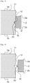
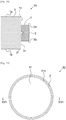
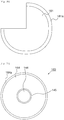
- Figure 1 shows a schematic plan view of a workpiece unit.
- Figure 2 shows a schematic sectional view of the workpiece unit on II-II line in Figure 1 .
- Figure 3 shows a schematic partial view of a holding member portion.
- Figure 4 shows a schematic sectional view in which the workpiece body and the holding member are exploded.
- the workpiece unit 10 comprises a workpiece body 1, and a holding member 2 arranged on at least one part of sidewall of the workpiece body 1.
- the workpiece body 1 is, for example, a substance which is machined by a machining apparatus.
- a dental product is produced from the workpiece body 1.
- a prosthetic material such as ceramic frame, full contour crown and the like, is exemplified. It is preferable that dental prosthetic material has a tooth crown shape.
- an orthodontic product for example, orthodontic bracket
- a dental implant product for example, dental implant abutment
- the holding member 2 assists holding or fixation of the workpiece unit 10 onto the machining apparatus. For example, when the workpiece unit is held or fixed onto the machining apparatus, at least the holding member 2 in the workpiece unit 10 is held by the machining apparatus.
- the workpiece body 1 comprises a first surface 1a, a second surface 1b on a side opposite to the first surface 1a, and a circumferential portion 1c arranged between the first surface 1a and the second surface 1b. It is preferable that the first surface 1a and the second surface 1b are parallel, or approximately parallel. It is preferable that the workpiece body 1 has a flat plate shape. Although the workpiece unit 10 and the workpiece body 1 has a circular plane shape in a mode shown in Figure 1 , it is not limited to the circular shape. It may have a plane shape, such as an elliptic and polygonal shape.
- the holding member 2 is arranged on at least one part of the circumferential portion 1c corresponding to a side surface of the workpiece body 1.
- the holding member 2 directly covers at least one part of the circumferential portion 1c on the workpiece body 1. It is preferable that the holding member 2 is arranged along the circumferential portion 1c in a successive manner. It is preferable that the holding member 2 has a shape according (or adapted) to a plane shape of the workpiece body 1.
- the holding member 2 may have, for example, a circular, annular, tubular, or ring shape. It is preferable that the holding member 2 arranged over an entire circumference of a sidewall of the workpiece body 1. A gap (or gaps) may be present between the holding member 2 and the workpiece body 1.
- the holding member 2 is attached to the workpiece body 1 without any intermediate adhesive material.
- An inner circumference portion 2c of the holding member 2 and the outer circumferential portion 1c of the workpiece body 1 directly contact each other on at least one part.
- the holding member 2 may comprise a first surface 2a directed in the same direction as the first surface 1a of the workpiece body 1, a second surface 2b directed in the same direction as the second surface 1b of the workpiece body 1, and the inner circumference portion 2c which is arranged between the first surface 2a and the second surface 2b and is directed to the circumferential portion 1c of the workpiece body 1. It is preferable that the first surface 2a of the holding member 2 and the first surface 1a of the workpiece body 1 are parallel or approximately parallel. It is preferable that the second surface 2b of the holding member 2 and the second surface 1b of the workpiece body 1 are parallel or approximately parallel.
- the first surface 2a of the holding member 2 may be present on a side closer to the second surface 1b of the workpiece body 1 than the first surface 1a of the workpiece body 1.
- the second surface 2b of the holding member 2 may be present on a side closer to the first surface 1a of the workpiece body 1b than the second surface 1b of the workpiece body 1. That is, it is preferable that the first surface 1a of the workpiece body 1 and the first surface 2a of the holding member 2 form a step. It is preferable that the second surface 1b of the workpiece body 1 and the second surface 2b of the holding member 2 form a step.
- the holding member 2 has a thickness t2 thinner than an entire thickness t1 of the workpiece body 1. Thereby, in a case where the workpiece unit 10 is fixed onto the machining apparatus, position adjustment may be carried out easily.
- the holding member 2 is arranged at the central area of the workpiece body 1 in a thickness direction of the workpiece body 1. That is, it is preferable that the center of the holding member 2 in the thickness direction overlaps with the center of the workpiece body 1 in thickness direction. Thereby, in a case where the workpiece unit 10 is set on the machining apparatus, position adjustment may be carried out easily.
- the workpiece unit 10 is symmetric with respect to an extending direction of the first surface 1a and second surface 1b of the workpiece body 1.
- the workpiece unit 10 may be set on the machining apparatus in a manner directed to a machining tool (usually upper side).
- the workpiece body 1 comprises at least one first positioning portion 1d at a part facing the holding member 2 in the circumferential portion 1c.
- the holding member 2 comprises at least one second positioning portion 2d at a part facing workpiece body 1 in the inner circumference portion 2c.
- the first positioning portion 1d and the second positioning portion 2d are portions for defining position of the holding member 2 relative to the workpiece body 1.
- the first positioning portion 1d and the second positioning portion 2d may provide and suppress displacement (or shifting) of the holding member 2 relative to the workpiece body 1.
- the first positioning portion 1d and the second positioning portion 2d may be arranged at mutually associated positions.
- the first positioning portion 1d and the second positioning portion 2d may have mutually associated shapes.
- the first positioning portion 1d and the second positioning portion 2d have positions and shapes where at least one part of either one is engaged, particularly fitted, with the other one.
- the first positioning portion 1d is formed as a concave portion.
- the second positioning portion 2d is formed as a convex portion which fits with the concave portion of the first positioning portion 1d. Positions of the first positioning portion 1d and the second positioning portion 2d may be anywhere, if the circumferential portion 1c of the workpiece body 1 and the inner circumference portion 2c of the holding member 2 are opposing to each other.
- the convex portion has a shape and size so as to contact to an opening and/or an inner wall of the concave portion.
- a width of the convex portion (for example, a size in a direction (vertical direction in the figure) connecting the first surface 1a and the second surface 1b of the workpiece body 1) is larger than a width (a size in vertical direction) of the concave portion.
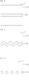
- Figure 5 to Figure 8 show schematic plan views of examples of the first positioning portion 1d and the second positioning portion 2d. Although plan views of the first positioning portion 1d are shown in Figure 5 to Figure 8 , the second positioning portion 2d also has a plane shape associated with a shape of the first positioning portion 1d. Illustration and explanation of the second positioning portion 2d are omitted.
- the first positioning portion 1d may be formed as, for example, a successive groove portion as shown in Figure 5 and Figure 6 .
- the first positioning portion 1d may be a straight groove portion as shown in Figure 5 and a groove portion having a zigzag or meandering shape as shown in Figure 6 .
- the first positioning portion 1d may be formed as at least one partial or separated dot concave part (for example, conical or columnar shape) as shown in, for example, Figure 7 and Figure 8 .
- a dotted line formed of the first positioning portions 1d may be straight as shown in Figure 7 or a zigzag or meandering shape as shown in Figure 8 .
- first positioning portions 1d having regular shapes is shown in Figure 5 to Figure 8 , the first positioning portion 1d may have an irregular shape.
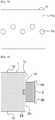
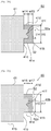
- first positioning portion 1d and the second positioning portion 2d have cross-sectional planes having one triangular shape in the modes shown in Figure 2 to Figure 4
- the first positioning portion 1d and the second positioning portion 2d may have different cross-sectional shapes.
- Figure 9 to Figure 12 show schematic partial views of examples of the first positioning portion 1d and the second positioning portion 2d.
- the first positioning portion 1d and the second positioning portion 2d may have a polygonal cross-sectional plane, such as a square cross-sectional plane, as shown in Figure 9 .
- the first positioning portion 1d may have a cross-sectional shape (hemispherical shape), such as a half circular or half elliptical shape, as shown in Figure 10 .
- the second positioning portion 2d may have a cross-sectional shape (hemispherical shape), such as a half circular or half elliptical shape, similar to that of the first positioning portion 1d, and also have a shape different from that of the first positioning portion 1d as shown in Figure 10 (a triangular shape in Figure 10 ).
- a part of the second positioning portion 2d may be engaged with the first positioning portion 1d as shown in Figure 11 .
- the second positioning portion 2d has a width w22 equivalent or more to a width w21 of the first positioning portion 1d.
- the first positioning portion 1d and the second positioning portion 2d may comprise a plurality of concave portions or convex portions in one cross-sectional plane.
- first positioning portion 1d and/or the second positioning portion 2d have a depth and/or height at which the first positioning portion 1d and the second positioning portion 2d may be engaged.
- the first positioning portion 1d and/or the second positioning portion 2d may have a depth and/or height of, for example, 0.5mm or more.
- the holding member 2 may have any thickness t2, if no trouble is provided in machining of the workpiece body 1 due to such thickness. It is preferable that the holding member 2 has a thickness t2 thinner than a thickness t1 of the workpiece body 1. It is for easy holding of the workpiece unit 10 onto the machining apparatus. It is preferable that the holding member 2 has a thickness t2 of 1 mm or more, preferably 2 mm or more, more preferably 4 mm or more. It is for retaining holding-strength by the machining apparatus.
- the holding member 2 may have a width w1 at which the workpiece unit 10 may be held onto the machining apparatus.
- ceramic, metal, resin etc. may be used as a material of the workpiece body 1.
- An example of the ceramic may be exemplified by material(s) containing at least one of zirconia, alumina and glass ceramics.
- An example of the metal may be exemplified by titanium, titanium alloy etc.
- An example of the resin may be exemplified by acryl resin, methacrylate resin, ABS (acrylonitrile buta diene styrene) resin, polycarbonate, polypropylene, polystyrene, polyester, polyether ketone, Teflon (registered trademark) etc.
- an example of the resin may be also exemplified by composite material (composite resin) where these resins are filled with inorganic filler.
- the workpiece body 1 may be semi-sintered zirconia in which zirconia crystal grains are fired, but not to be a completely sintered state.
- the semi-sintered zirconia contains a stabilizer which suppresses phase transition in zirconia and crystal phase of zirconia. For example, when it is converted into a sintered body, the stabilizer suppresses phase transition in the crystal phase of the sintered body from tetragonal to monoclinic shape.
- the stabilizer may be exemplified by oxides, such as, for example, calcium oxide (CaO), magnesium oxide (MgO), yttrium oxide (Y2O3), cerium oxide (CeO2) etc. It is preferable that the stabilizer is supplied at an amount at which tetragonal zirconia grains may be partially stabilized.
- content ratio of yttria is preferably 2 mol% to 8 mol%, more preferably 2.5 mol% to 6.5 mol%, relative to total mol of zirconia and yttria.
- phase transition may be suppressed, however, bending strength and fracture toughness would be reduced.
- a too small content ratio of the stabilizer reduction in bending strength and fracture toughness may be suppressed, however, suppression of progress in phase transition would be insufficient.
- zirconia which is partially stabilized by addition of the stabilizer is referred to as "partially stabilized zirconia".
- the content ratio of the stabilizer in the sintered zirconia can be measured by, for example, Inductively Coupled Plasma (IPC) emission spectrometric analysis, X-ray fluorescence analysis and the like.
- IPC Inductively Coupled Plasma
- An entire size d1 of the workpiece body 1 and a thickness t1 of the workpiece body 1 may be appropriately designed according to a purpose.
- material of the holding member 2 is a material which is not greatly deformed due to pressure upon fixation when it is fixed onto the machining apparatus.
- material of the holding member 2 is a material which may be attached onto the workpiece body 1 by methods explained below.
- the material of the holding member 2 utilized are, for example, engineering plastic, polypropylene, polystyrene, acryl resin, ABS (acrylonitrile buta diene styrene) resin, polycarbonate, polyester, polyether ketone, Teflon (registered trademark), metal, wood etc.
- above examples of the resin may also include composite material (composite resin) in which the resin is filled with inorganic filler.
- Information may be attached onto the holding member 2.
- the information may be provided at a visually recognizable position on the holding member 2 by lettering, marking, seal, etc. with symbols, such as letters, a bar code etc.
- the information may include, for example, a lot number, a color (shade), a shrinkage ratio (loss ratio by shrinkage upon sintering), a discrimination for upper/lower sides, etc.
- a workpiece body 1 is produced.
- Partially stabilized zirconia powder as zirconia particles containing a stabilizer is prepared.
- Type and concentration of the stabilizer may be pertinently selected.
- a preferable particle diameter and a particle diameter distribution of zirconia crystal grains are pertinently selected.
- a preferable method such as a hydrolysis method, neutralization coprecipitation method, an alkoxide method, a solid phase method etc., may be selected appropriately.
- An additive is supplied and mixed with the prepared partially stabilized zirconia powder, if required. In a case of wet blending, a composition is dried.
- the composition is formed into a predetermined shape by pressure formation.
- the composition is pressurized to form a shaped of the workpiece body 1.
- a preferable method may be appropriately selected as the pressure formation method.
- a pressurizing pressure may be, for example, 20MPa or more.
- the composition for sintering may be further subjected to CIP (Cold Isostatic Pressing) at a pressure of 150MPa or more.
- CIP Cold Isostatic Pressing
- a formed body may be machined into a desired shape by cutting, grinding, etc.
- the formed body is fired at a temperature at which the zirconia particles are not sintered so as to form a semi-sintered body.
- a semi-sintering condition may be at a semi-sintering temperature of 800°C to 1200°C, and for a keeping time of 1 hour to 12 hours.
- the semi-sintered body may be machined into a desired configuration by cutting, grinding, etc.
- the semi-sintered body may be formed into a shape of the workpiece body 1 (also a projecting portion is formed) after the semi-sintered body has been produced, instead of formation into a shape of the workpiece body 1 upon shape forming. Thereby, a workpiece body 1 is produced.
- a holding member 2 is prepared.
- Producing method for the holding member 2 is not specifically limited.
- the holding member 2 may be produced by injection molding, extrusion molding, cutting machining (cutting out formation), etc.
- the holding member 2 is heated to be expanded.
- Heating temperature for the holding member 2 may be appropriately set according to the material of the holding member 2.
- the heating temperature for the holding member 2 is preferably 60°C or more, more preferably 80°C or more.
- the heating temperature for the holding member 2 is preferably 150°C or less, and may be, for example, 120°C or less, or 100°C or less.
- the holding member 2 is expanded, the workpiece body 1 is fitted into the holding member 2 so that a first positioning portion 1d of the workpiece body 1 and a second positioning portion 2d are fitted together.
- positioning of the holding member 2 and the workpiece body 1 is performed and then the holding member 2 is cooled.
- the holding member 2 shrinks due to cooling.
- the holding member 2 is attached onto the workpiece body 1 (so-called shrink fitting method).
- the holding member 2 may be attached onto the workpiece body 1 without using any adhesive material.
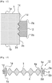
- Figure 13 and Figure 14 show a schematic cross-sectional view of an example of a workpiece unit after machining of a workpiece body 1.
- Figure 14 is a schematic partial view of a part of the first positioning portion 1d and the second positioning portion 2d.
- the workpiece unit 10 is set on a machining apparatus, and the workpiece body 1 is machined by cutting out and the like to form a machined item 4.
- the machined item 4 may be cut out into a connected state to an outer edge portion 1e while the outer edge portion 1e of the workpiece body is allowed to remain in a frame-shape.
- the machined item 4 is, for example, a dental product as described above. Due to formation of the machined item 4, a cut-off part 5 which has been cut off is formed on the workpiece body 1.
- the outer edge portion 1e is formed along a circumferential portion 1c due to formation of the machined item 4 and the cut-off part 5.
- the outer edge portion 1e is a machining margin which acts as a frame of the machined item 4.
- the machined item 4 is connected to the outer edge portion 1e via a connecting part 4a. It is preferable that the first positioning portion 1d has a shape which provides no negative effects, such as dropping off of the machined item 4, after machining.
- the holding member 2 may be attached onto the workpiece body 1 at a pertinent position by engaging the first positioning portion 1d and the second positioning portion 2d.
- the first positioning portion 1d and the second positioning portion 2d play a role as a stopper against slipping, resulting in that displacement (position shifting) of the holding member 2 relative to the workpiece body 1 may be suppressed.
- no adhesive material is used for attachment of the holding member 2. Therefore, even in a case of being subjected to a high temperature after machining, damage onto the workpiece body 1 may be suppressed, the damage being caused through stress applied to the workpiece body 1 by the holding member 2 due to difference between a heat expansion coefficient of the workpiece body 1 and a heat expansion coefficient of the holding member 2. In addition, in a case where it is desired that the holding member 2 is detached from the workpiece body 1 after machining, the holding member 2 may be easily detached.
- the holding part to be held by the machining apparatus is not formed by the workpiece body 1 itself, instead the holding member 2 replaces the role of the holding part, and thus a mold for producing the workpiece body 1 may be downsized by a width of the holding member 2. Therefore, consumption amount of low material for the workpiece body 1 can be reduced. In a case where cost for the workpiece body 1 is higher than that of the holding member 2, production cost for the workpiece unit 10 and the machined item 4 can be reduced.
- Figure 15 shows a schematic partial view of a workpiece unit according to the second exemplary embodiment.
- a workpiece unit 20 further comprises adhesive material 3 for jointing a workpiece body 1 and a holding member 2. That is, the workpiece body 1 and the holding member 2 are jointed with the adhesive material 3 on at least a part. It is preferable that the adhesive material 3 is arranged in a region where the workpiece body 1 and the holding member 2 face each other. It is preferable that material of the adhesive material 3 is a material which provides no displacement between the workpiece body 1 and the holding member 2. As the adhesive material 3, for example, thermosetting resin, photosetting resin and the like may be used.
- a producing method of the workpiece unit 20 may be the same as that of the producing method of the first exemplary embodiment, with the proviso that the workpiece body 1 and the holding member 2 may be jointed with the adhesive material 3 in the second exemplary embodiment. Therefore, in a case of using a holding member which cannot be applied to the shrink fitting method, the second exemplary embodiment may be preferably applied.
- the other modes (details) in the second exemplary embodiment other than those described above may be the same as those in the first exemplary embodiment.
- the adhesive material may be applied to each mode shown in the first exemplary embodiment.
- the second exemplary embodiment may be combined with at least one mode above, if possible.
- the second exemplary embodiment can also exert positioning effect and displacement prevention effect like as the first exemplary embodiment. According to the second exemplary embodiment, attachment strength of holding member 2 onto the workpiece body 1 may be enhanced.
- Figure 16 shows a schematic partial view of the workpiece unit according to the third exemplary embodiment.
- the first positioning portion of the workpiece body is a concave portion and the second positioning portion of the holding member is a convex portion.
- a concave portion and a convex portion are inversely positioned between the workpiece body 1 and the holding member 2. That is, a first positioning portion 1f disposed on the circumferential portion 1c of the workpiece body 1 is a convex portion.
- a second positioning portion 2f disposed on the inner circumference portion 2c of the holding member 2 is a concave portion associated with the first positioning portion 1f.
- a producing method of the workpiece unit 30 may be the same as that of the producing method of the first exemplary embodiment.
- the other modes (details) in the third exemplary embodiment other than those described above may be the same as those in the first exemplary embodiment.
- the third exemplary embodiment may be combined with at least one mode above, if possible.
- the workpiece body 1 and the holding member 2 may be jointed with the adhesive material (figures are omitted) like as the second exemplary embodiment.
- the third exemplary embodiment may exert effects similar with those of the first exemplary embodiment.
- Figure 17 shows a schematic plan view of a workpiece unit.
- Figure 18 shows a schematic cross-sectional view of the workpiece unit taken along XVII-XVII line in Figure 17 .
- Figure 19 shows a schematic partial view of a holding member portion.
- a workpiece body 41 further comprises a projecting portion 41c in addition to the configuration of the first exemplary embodiment.
- the holding member 2 is disposed on at least one part of the projecting portion 41c.
- a first positioning portion 41h is disposed on the projecting portion 41c.
- the workpiece body 41 comprises a first surface 41a dedicated to be a machining target surface and a second surface 41b on a side opposite to the first surface 41a. It is preferable that the first surface 41a and the second surface 41b are parallel or approximately parallel. It is preferable that the workpiece body 41 has a flat plate shape. Although the workpiece unit 40 and the workpiece body 41 have a circular plane shape in a mode shown in Figure 17 , the shape is not limited to circle, thus they may have a plane shape, such as an ellipse, a polygon, etc.
- the workpiece body 41 comprises a projecting portion 41c along at least one part of a sidewall, that is on an outer edge of the first surface 41a and the second surface 41b or on a circumferential portion 41g between the first surface 41a and the second surface 41b. It is preferable that the projecting portion 41c is a portion for holding the workpiece unit 40 onto the machining apparatus. It is preferable that the projecting portion 41c is disposed on a region which is not machined by the machining apparatus. It is preferable that the projecting portion 41c is arranged over an entire circumference of the circumferential portion 41g on the workpiece body 41 in a successive manner. That is, it is preferable that projecting portion 41c has a ring shape or an annular shape.
- the projecting portion 41c may have a shape such that it projects from a side surface of the workpiece body 41.
- the projecting portion 41c projects (from an area) between the first surface 41a and the second surface 41b of the workpiece body 41 in an approximately vertical [sic, parallel] direction relatively to the first surface 41a and the second surface 41b.
- the projecting portion 41c is arranged on the circumferential portion 41g of the workpiece body 41 and has such a shape that an end part of the workpiece body 41 is thinner than the other part.
- the projecting portion 41c may comprise a third surface 41d directed in the same direction as the first surface 41a and a fourth surface 41e directed in the same direction as the second surface 41b.
- the projecting portion 41c may comprise a fifth surface 41f connecting the third surface 41d and the fourth surface 41e. It is preferable that the third surface 41d and the fourth surface 41e are parallel or approximately parallel. It is preferable that the third surface 41d and the first surface 41a are parallel or approximately parallel. It is preferable that the fourth surface 41e and the second surface 41b are parallel or approximately parallel. It is preferable that the third surface 41d and the fifth surface 41f are vertical or approximately vertical one another. It is preferable that the fourth surface 41e and the fifth surface 41f are vertical or approximately vertical.
- the first surface 41a and the second surface 41b are vertical or approximately vertical to the fifth surface 41f. It is preferable that a thickness t12 of the projecting portion 41c is thinner than an entire thickness t11 of the workpiece body 41. That is, it is preferable that the first surface 41a and the third surface 41d form a step. It is preferable that the second surface 41b and the fourth surface 41e form a step. Thereby, in a case where the workpiece unit 40 is fixed onto the machining apparatus, positioning may be easily carried out.
- the first surface 41a and the third surface 41d may form the same plane.
- the second surface 41b and the fourth surface 41e may form the same plane.
- a thickness t12 of the projecting portion 41c is preferably 1 mm or more, more preferably 2 mm or more, further preferably 4 mm or more. It is for holding of the workpiece unit 40 upon machining and reinforcement of the machined workpiece body 41.
- a width w11 of the projecting portion 41c is preferably 2 mm or less, more preferably 1.7 mm or less, and further preferably 1.5 mm or less. It is because that too large width w11 of the projecting portion 41 results in enlargement of useless parts in the workpiece body 41.
- the width w11 of the projecting portion 41c is preferably 0.3 mm or more, preferably 0.4 mm or more, more preferably 0.6 mm or more, further preferably 0.8 mm or more.
- the projecting portion 41c has an effect for reinforcement of the machined workpiece body 41. Therefore, in order to reinforce the machined workpiece body 41, a constant width is required for the projecting portion 41c.
- the projecting portion 41c is arranged in the central area of the workpiece body 41 in a thickness direction of the workpiece body 41. That is, it is preferable that the central area of the projecting portion 41c in a thickness direction overlaps with the center of the workpiece body 41 in a thickness direction. Thereby, in a case where the workpiece unit 40 is set on the machining apparatus, positioning adjustment may be easily carried out.
- An entire size d12 of the workpiece body 41 and a size d13 of the first surface 41a and the second surface 41b dedicated to be a machining target surface of the workpiece body 41 may be appropriately designed according to a purpose.
- the holding member 2 is arranged on at least one part of outside of the projecting portion 41c. It is preferable that the holding member 2 is arranged in at least a projection direction of the projecting portion 41c. It is preferable that the holding member 2 is arranged along the fifth surface 41f corresponding to a side surface of the projecting portion 41c in a successive manner. That is, the holding member 2 may cover at least one part of the fifth surface 41f of the projecting portion 41c.
- the fifth surface 41f of the projecting portion 41c faces the inner circumference portion 2c of the holding member 2. In a case of no interposed adhesive material, the fifth surface 41f of the projecting portion 41c and the inner circumference portion 2c of the holding member 2 directly contact each other at least partially.
- first surface 2a of the holding member 2 and the third surface 41d of the workpiece body 41 are parallel or approximately parallel. It is preferable that the second surface 2b of the holding member 2 and the fourth surface 41e of the workpiece body 41 are parallel or approximately parallel.
- the third surface 41d of the projecting portion 41c and the first surface 2a of the holding member 2 may form the same plane.
- the fourth surface 41e of the projecting portion 41c and the second surface 2b of the holding member 2 may form the same plane. It is aimed at complete overlapping of the holding member 2 and the projecting portion 41c. In such case, a thickness t13 of the holding member 2 is the same with a thickness t12 of the projecting portion 41c.
- the first surface 2a of the holding member 2 may be present on a side closer to the first surface 41a of the workpiece body 41 than the third surface 41d of the projecting portion 41c.
- the second surface 2b of the holding member 2 may be present on a side closer to the second surface 41b of the workpiece body 41 than the fourth surface 41e of the projecting portion 41c. It is aimed at easy holding of the workpiece unit 40 onto the machining apparatus. In such case, a thickness t13 of the holding member 2 is thicker than a thickness t12 of the projecting portion 41c.
- the thickness t13 of the holding member 2 may be any thickness if no problem is provided in machining of the workpiece body 41.
- a thickness t13 of the holding member 2 is preferably thinner than a thickness t1 of the workpiece body 41, more preferably equivalent to a thickness t12 of the projecting portion 41c. It is aimed at easy holding of the workpiece unit onto the machining apparatus.
- the thickness t13 of the holding member 2 is preferably 1 mm or more, more preferably 2 mm or more, further preferably 4 mm or more. It is for maintaining of holding strength by the machining apparatus.
- a width w12 of the holding member 2 is a width at which it may be held by the machining apparatus together in combination with a width w11 of the projecting portion 41c.
- the first positioning portion 41h of the workpiece body 41 may be arranged on the fifth surface 41f of the projecting portion 41c.
- the second positioning portion 2d of the holding member 2 may be arranged at a position associated with the first positioning portion 41h. Shapes of the first positioning portion 41h and the second positioning portion 2d may be the same as those in the first exemplary embodiment.
- a producing method of the workpiece unit 40 may be the same as that of the producing method of the first exemplary embodiment.
- the shape of the projecting portion and the holding member may be different from those shown in Figure 17 to Figure 19 .
- Figure 20 to Figure 23 show other examples of the projecting portion and the holding member.
- the holding member 52 may be arranged so as to cover not only the fifth surface 41f of the projecting portion 41c, but also at least one part of third surface 41d and the fourth surface 41e. That is, the holding member 52 may comprise a groove portion receiving the projecting portion 41c at the side of the workpiece body 41. The holding member 52 may be arranged so that the projecting portion 41c fits to (in or on) the groove portion. Modes (details) of the first positioning portion 41h and the second positioning portion 52a may be the same as those described above.
- a width w14 of the projecting portion 41c is the same with a width w11 shown in Figure 18 . It is preferable that a width (w14+w15) of the holding member 52 is the same with a width (w11+w12) shown in Figure 18 . It is preferable that a thickness t14 of the projecting portion 41c is 1 mm or more in order to ensure strength. It is preferable that a thickness t15 of the holding member 52 is equivalent or less than that of the workpiece body 41 in order to be held on the machining apparatus.
- the holding member 62 may be arranged so as to cover the fifth surface 41f and one of the third surface 41d and the fourth surface 41e, of the projecting portion 41c. In a mode shown in Figure 21 , the holding member 62 is arranged so as to cover the third surface 41d and the fifth surface 41f of the projecting portion 41c.
- the holding member 62 comprises a first surface 62a directed in the same direction as the second surface 41b and the fourth surface 41e of the workpiece body 41. It is preferable that in the holding member 62, the first surface 62a forms a same plane as the fourth surface 41e of the projecting portion 41c, or is arranged so as to be present on a side closer to the second surface 41b than the fourth surface 41e of the projecting portion 41c. It is aimed at stabilization in attachment of the workpiece unit 60 onto the machining apparatus. Modes of the first positioning portion 41h and the second positioning portion 62b may be the same as those described above. It is preferable that the holding member 62 is arranged at a central area in a thickness direction of the workpiece body 41. In such case, the position of the projecting portion 41c may be displaced from the center in a thickness direction of the workpiece body 41.
- a width w16 of the projecting portion 41c is equivalent to a width w11 shown in Figure 18 . It is preferable that a width (w16+w17) of the holding member 52 is equivalent to a width (w1+w2) shown in Figure 18 . It is preferable that a thickness t16 of the projecting portion 41c is 1 mm or more in order to ensure strength. It is preferable that a thickness t17 of the holding member 62 is equivalent to or less than that of the workpiece body 41 in order to be held on the machining apparatus.
- the holding member 72 comprises 2 or more components (parts).
- Figure 23 shows a plan view of the holding member 72 seen from a side of the side surface.
- the holding member 72 comprises a first part 72a covering the third surface 41d of the projecting portion 41c and a second part 72b covering the fourth surface 41e of the projecting portion 41c.
- the fifth surface 41f of the projecting portion 41c is covered by the first part 72a and the second part 72b.
- the first part 72a and the second part 72b respectively comprise at least one engaging portion at a side directed to the fifth surface 41f of the projecting portion 41c.
- first part 72a and the second part 72b are arranged on the side directed to the fifth surface 41f of the projecting portion 41c so that a concave portion and a convex portion fit each other.
- a boundary between the first part 72a and the second part 72b has a meandering shape.
- Modes of the first positioning portion 41h and the second positioning portion 72c may be the same as those described above.
- first part 72a and the second part 72b regions where the concave portion and the convex portion are formed have the same shape. It is preferable that the first part 72a and the second part 72b have the same shape as a whole. It is more preferable that the first part 72a and the second part 72b are the same components. In such case, production and management of the holding member 72 may be simplified.
- each part of the holding member 72 may be prevented from displacement by arranging an engaging portion on each part.
- the holding member 72 comprises a plurality of parts, attachment of the holding member 72 onto the workpiece body 41 may be easily carried out.
- the other modes in the fourth exemplary embodiment other than those described above may be the same as those in the first exemplary embodiment.
- the fourth exemplary embodiment may be combined with at least one mode mentioned above, if possible.
- the workpiece body and the holding member may be jointed with the adhesive material (figures are omitted) like as the second exemplary embodiment.
- Each mode in the fourth exemplary embodiment shows a mode where the first positioning portion of the workpiece body is a concave portion and the second positioning portion of the holding member is a convex portion.
- the concave portion and the convex portion may be inversely positioned between the workpiece body and the holding member like as the third exemplary embodiment. That is, the first positioning portion arranged on the projecting portion of the workpiece body may be defined as a convex portion, and the second positioning portion arranged on the inner circumference portion of the holding member may be defined as a concave portion (figures are omitted).
- each mode of the fourth exemplary embodiment shows a mode where the first positioning portion 41h of the workpiece body 41 is present on the fifth surface 41f of the projecting portion 41c
- the first positioning portion 41h may be arranged on at least one of the third surface 41d and the fourth surface 41e of the projecting portion 41c.
- the second positioning portion may be arranged at a position associated with the first positioning portion.
- the fourth exemplary embodiment may exert the same effect as that of the first exemplary embodiment.
- the machined workpiece body 41 further comprises a projecting portion 41c on an outer edge portion 1e.
- the machined item 4 is connected to at least one of the outer edge portion 1e and the projecting portion 41c.
- the outer edge portion of the workpiece body 41 may be reinforced by the projecting portion 41c according to the workpiece unit 40 of the present disclosure. That is, the thickness of the outer edge portion of the workpiece body 41 may be partially secured by the projecting portion 41c.
- a workpiece body comprises a plurality of components.
- Figure 24 shows a schematic plan view of a workpiece unit according to the fifth exemplary embodiment.
- Figure 25 shows a schematic cross-sectional view of the workpiece unit on XXIV-XXIV line in Figure 24 .
- a workpiece body 141 is physically divided into a plurality of divided sections 142.
- One workpiece body 141 is configured by assembling the plurality of divided sections 142.
- At least two divided sections 142 among the plurality of divided sections 142 may respectively have a different composition.
- each divided sections 142 may respectively contain a different coloring material.
- At least two divided sections 142 among the plurality of divided sections 142 may have the same composition, and all of the divided sections 142 may have the same composition.
- Main material of each divided section 142 may be the same or different. It is preferable that one divided section 142 has a size smaller than that capable of being held or fixed onto the machining apparatus.
- At least one of the plurality of divided sections 142 may be a part to be machined by the machining apparatus. At least one of the plurality of divided sections 142 may be a part not to be machined by the machining apparatus. At least one of the plurality of divided sections 142 may be a dummy workpiece body for supplementing the size (filling a gap) of the workpiece body 141 so that the workpiece body 141 has a size capable of being held by the machining apparatus.
- the workpiece body 141 is divided into each of the divided sections 142 in a manner such that a first surface 141a and a second surface 141b of the workpiece body 141 are divided.
- the number of the divided sections 142 per one workpiece body 141 may be appropriately set.
- the size of one divided section 142 may be appropriately adjusted according to needs and the like, such as each composition, etc.
- the plurality of divided sections 142 may be different or the same in size respectively.
- At least one divided section 142 may comprise at least one part of the first positioning portion 141d of the workpiece body 141. Modes of the first positioning portion 141d may be the same as those described above. The first positioning portion 141d may be successive by assembling the plurality of divided sections 142.
- At least one divided section 142 may comprise at least one part of the projecting portion 141c of the workpiece body 141. Modes of the projecting portion 141c may be the same as those of the exemplary embodiments above mentioned.
- the projecting portions 141c may be successive by assembling the plurality of divided sections 142.
- Each of the divided sections 142 may have any shape.
- the plurality of divided sections 142 may respectively be different or the same in shape.
- the divided sections 142 divide the workpiece body 141 in a manner crossing the center of the circular shape.
- a divided section 142 may have a plane sector shape.
- the sector shapes have the same radius.
- the plurality of divided sections 142 may be radially assembled in a manner that their arcs are successive so that a workpiece body 141 having a circular or ellipse shape may be configured.
- each sector shape may have any central angle, for example, 45°, 60°, 90°, 120°, 180° (that is, half circle, half ellipse, etc.) 240°, 270°, 300°, 315° and the like.
- the plurality of divided sections 142 respectively has the same thickness.
- both of the first surface 141a and the second surface 141b may be formed in plane respectively.
- position adjustment in thickness direction may be easily carried out upon fixation of the workpiece unit 140 onto the machining apparatus.
- the workpiece body 141 comprises a first divided section 142a, a second divided section 142 and a third divided section 142c.
- the first divided section 142a, the second divided section 142b and the third divided section 142c have the same shape.
- the first divided section 142a, the second divided section 142b and the third divided section 142c have the same size.
- the first divided section 142a, the second divided section 142b and the third divided section 142c have a plane shape in which both surfaces have a sector shape.
- a central angle of the sector shape is 120°.
- the first divided section 142a, the second divided section 142b and the third divided section 142c are radially arranged so as to form a circular workpiece body 141. Both surfaces of the first divided section 142a, the second divided section 142b and the third divided section 142c are respectively arranged on the same plane, and a first surface 141a and a second surface 141b are formed in respective planes.
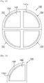
- Figure 26 to Figure 29 show a schematic plan view of a workpiece body, showing an example of plane shape of divided sections.
- Figure 26 to Figure 29 show a state where the divided sections forming one workpiece body are separated (i.e. exploded).
- the divided sections 142a, 142b, 142c have a plane sector shape having a central angle of 120°.
- the divided sections 142a, 142b have a plane half circular shape.
- the divided sections 142a have a plane half circular shape
- the divided sections 142b, 142c have plane sector shape having a central angle of 90°.
- each divided section has the same radius.
- the divided sections 142a to 142f do not have a plane sector shape, but being configured so as to form a circle when they are assembled.
- Figure 30 shows a schematic plan view of a workpiece body, showing another mode of the workpiece body.
- Adjacent divided sections 142 may directly contact each other.
- the workpiece body 141 may further comprise cushioning (buffer) material 143 on at least one part between adjacent divided sections 142.
- the cushioning material 143 is a material capable of smoothing unevenness (depressions and protrusions) on end surfaces of the divided sections 142.
- the cushioning material 143 may be adhesive material jointing the divided sections 142 each other.
- a resin sheet may be used as the cushioning material 143.
- Figure 30 shows a mode where the cushioning material 143 is entirely arranged at gaps between the divided sections 142
- the cushioning material 143 may be partially arranged at gaps between the divided sections 142.
- the cushioning material 143 inconsistency upon assembling due to unevenness on end surfaces of the divided sections 142 may be suppressed.
- the adhesive material is used as the cushioning material 143, joint strength between divided sections 142 may be enhanced.
- Figure 31 shows a schematic side view of the workpiece body, showing another mode of the workpiece body.
- the divided section 142 may comprise an engaging portion for engagement with an adjacent divided section 142 on an end surface directed to the adjacent divided sections 142.
- the engaging portion may be, for example, a concave portion 142g formed on an end surface of the divided section 142 and a convex portion 142h which is formed on an end surface of the and divided section 142b and fits to the concave portion 142g.
- the workpiece body 141 may further comprise cushioning material 143 as shown in Figure 30 .
- a divided section 142 is used as a divided section which is not to be machined (a dummy workpiece body), as a material for the divided section which is not to be machined, in addition to those described above, any material is useable that is capable of holding the workpiece unit 140 on the machining apparatus and has a strength capable of machining a divided section 142 to be machined.
- the other modes in the fifth exemplary embodiment other than those described above may be the same as those in the first to fourth exemplary embodiments.
- the fifth exemplary embodiment may be combined with at least one mode mentioned above, if possible.
- the workpiece body may comprise a plurality of divided sections having different compositions. Size and shape of each divided section may be adjusted, if necessary. Thereby, utilization efficiency of the workpiece body is enhanced, thus waste workpiece bodies may be reduced.
- the workpiece body may be sold per unit of one divided section. Furthermore, machined items having different compositions may be produced at one machining process by the machining apparatus.
- FIG. 32 shows a schematic plan view of a workpiece unit in the sixth exemplary embodiment.
- Figure 33 shows a schematic plan view of a section unit in the sixth exemplary embodiment.
- one holding member is applied to one divided section.
- a part of the holding member is arranged for every divided section.
- a workpiece unit 150 comprises a plurality of section units 151.
- Each of the section units 151 comprises a divided section 142, and a cover member 152 arranged on at least one part on a side surface of the divided section 142.
- the divided section 142 may be the same as the divided section of the fifth exemplary embodiment.
- Size of one section unit 151 may have a smaller size than that capable of being held on the machining apparatus.
- a cover member 152 surrounds circumferential portion (side surface) of the divided section 142.
- the cover member 152 may be the same as the holding members of the first to fifth exemplary embodiments, excepting that the cover member 152 surrounds one divided section.
- the cover members 152 form a holding member held by the machining apparatus.
- a part of one cover member 152 configures a part of the holding member.
- parts of the cover members 152 arranged on arc site (portion) of the divided sections 142 configure the holding member.
- a part of the cover member 152 which does not configure the holding member may act as a cushioning portion for smoothing joint with an adjacent divided section.
- the section units 151 may be jointed each other with adhesive material (not shown).
- an engaging portion may be arranged at a part where the cover members 152 face each other, for engagement of the cover members 152 each other.
- Figure 34 shows a schematic plan view of a section unit in another mode different from the mode shown in Figure 33 .
- the cover member is arranged over an entire circumference of the divided section.
- the cover member 154 is arranged on one site (portion) on a side surface of the divided section 142.
- the section unit 153 may be assembled like as the assembled portions shown in Figure 32 so as to form a workpiece unit as shown in Figure 24 .
- the cover members 154 are arranged at sites which act as the holding member.
- the cover member 154 is arranged along an arc portion of the divided section 142.
- the cover member 154 is not arranged at a part facing a divided section 142 which is adjacent to it when they are assembled.
- the section unit 153 shown in Figure 34 is the same with the modes of the section unit shown in Figure 33 , expecting that arrangement position of the cover member 154 is different.
- the section units 153 may be jointed each other with adhesive material (not shown). Or, an engaging portion may be arranged at an area where the divided sections 142 face each other for engagement of the divided sections 142 each other.
- the other modes in the sixth exemplary embodiment other than those described above may be the same as those in the first to fifth exemplary embodiments.
- the sixth exemplary embodiment may be combined with at least one mode mentioned above, if possible.
- the sixth exemplary embodiment may exert effects similar with those of the first to fifth exemplary embodiments. Since the section unit may be produced or sold per section unit, a user may produce or purchase a desired section unit and design (set) a desired combination of the compositions in a workpiece unit.
- FIG. 35 shows a schematic plan view of a workpiece unit in the seventh exemplary embodiment.
- Figure 36 shows a schematic plan view of a dummy workpiece body in the seventh exemplary embodiment.
- a plurality of section units are assembled to form a workpiece unit.
- a workpiece unit 160 is configured using one section unit.
- the workpiece unit 160 comprises a section unit 151 and a dummy workpiece body 161.
- the section unit 151 is the same as the section unit 151 of the sixth exemplary embodiment.
- the dummy workpiece body 161 is intended to compensate a size of the section unit 151 so that the section unit 151 may be held on the machining apparatus.
- the dummy workpiece body 161 may comprise a holding portion 161a for holding on the machining apparatus.
- the holding portion 161a has functions similar to those of the holding member.
- the holding portion 161a may be integrally formed as a part of the dummy workpiece body 161, or formed by another (separate) member.
- the dummy workpiece body 161 has a plane shape such that three section units 151 are assembled. In the modes shown in Figure 35 and Figure 36 , the dummy workpiece body 161 has a plane shape in which it is assembled with the section unit 151 to form a circle shape.
- the shape and size of the dummy workpiece body 161 may be designed so as to adapt with the shape and size of the section unit 151.
- the dummy workpiece body 161 has a thickness capable of being held on the machining apparatus.
- Material of the dummy workpiece body 161 may be any material if it may be held on the machining apparatus and realize machining of the divided section.
- the dummy workpiece body 161 and the section unit 151 may be jointed with, for example, adhesive material (not shown).
- engaging portions may be arranged at an area where the dummy workpiece body 161 and the section unit 151 face each other for engagement of the dummy workpiece body 161 and the section unit 151.
- the dummy workpiece body 161 may be used repeatedly. It is preferable that the section unit 151 may be detached from the dummy workpiece body 161.
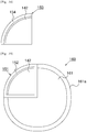
- FIG 37 shows a schematic plan view of a workpiece unit of another mode different from the mode shown in Figure 35 .
- a workpiece unit 163 comprises a divided section (workpiece body) 144, a dummy workpiece body 164 holding the divided section 144, and adhesive material 145 jointing the divided section 144 and the dummy workpiece body 164.
- the dummy workpiece body 164 has an annular or tubular structure having an opening cut off in a size of the divided section 144.
- the dummy workpiece body 164 may comprise a holding part 164a for holding onto the machining apparatus.
- the divided section 144 is fitted to the opening dummy workpiece body 164 in a concentric manner and jointed with the adhesive material 145.
- a size of the divided section 144 (for example, radius) may be 80% or less, 60% or less, 50% or less, or 40% or less of a size (for example, radius) capable of being held onto the machining apparatus.
- the dummy workpiece body 164 has a strength so as not to be deformed upon machining by the machining apparatus.
- the other modes in the seventh exemplary embodiment other than those described above may be the same as those in the first to sixth exemplary embodiments.
- the seventh exemplary embodiment may be combined with at least one mode mentioned above, if possible.
- the seventh exemplary embodiment may exert effects similar to those of the first to sixth exemplary embodiments. It is not required to enlarge the workpiece body to a size capable of being held onto the machining apparatus. Thereby, even in a case of a composition of poor demand, machining may be carried out without using any workpiece body having another (different) composition.
- a workpiece unit according to an eighth exemplary embodiment of the present disclosure will be explained.
- the divided sections are physically separated from one another.
- at least 2 divided sections in the workpiece body are not physically separated, and they may be integrally formed.
- a schematic plan view and a schematic sectional view of the workpiece unit in the eighth exemplary embodiment may be the same as those in the Figure 24 and Figure 25 .
- adjacent divided sections 142 are in a bonded (or jointed) state. Therefore, materials of the adjacent divided sections 142 are preferably those capable of being bonded by firing, more preferably those containing the same main material.
- the adjacent divided sections 142 may be zirconia having different type and/or content ratio in additive(s), such as coloring agent, etc.
- a producing method of the workpiece unit of the eighth exemplary embodiment is the same as the producing methods explained in exemplary embodiments mentioned above, expecting that a plurality of divided sections are integrally formed.
- a detachable partition is arranged on a mold so as to form a mold for divided sections having a desired shape. That is, the partition is positioned at a boundary of the divided sections.
- regions for each of the divided sections are charged with compositions, then the partition is removed.
- the compositions are subjected to pressurizing formation so that a formed body in which plural compositions are integrated can be formed.
- a method subsequent to sintering of the formed body is the same as those of the exemplary embodiments mentioned above.
- the other modes in the eighth exemplary embodiment other than those described above may be the same as those in the first to seventh exemplary embodiments.
- the eighth exemplary embodiment may be combined with at least one exemplary embodiment mentioned above, if possible.
- the eighth exemplary embodiment may exert effects similar to those of the first to seventh exemplary embodiments.
- it requires no members for holding the plurality of divided sections, such as a holding member, adhesive material, etc.
- the present disclosure may be applied to for example, a product of dental prosthetic material.
Landscapes
- Health & Medical Sciences (AREA)
- Oral & Maxillofacial Surgery (AREA)
- Dentistry (AREA)
- Epidemiology (AREA)
- Life Sciences & Earth Sciences (AREA)
- Animal Behavior & Ethology (AREA)
- General Health & Medical Sciences (AREA)
- Public Health (AREA)
- Veterinary Medicine (AREA)
- Engineering & Computer Science (AREA)
- Chemical & Material Sciences (AREA)
- Ceramic Engineering (AREA)
- Orthopedic Medicine & Surgery (AREA)
- Jigs For Machine Tools (AREA)
- Dental Tools And Instruments Or Auxiliary Dental Instruments (AREA)
- Dental Prosthetics (AREA)
- Constituent Portions Of Griding Lathes, Driving, Sensing And Control (AREA)
- Finish Polishing, Edge Sharpening, And Grinding By Specific Grinding Devices (AREA)
- Clamps And Clips (AREA)
- Snaps, Bayonet Connections, Set Pins, And Snap Rings (AREA)
Applications Claiming Priority (2)
| Application Number | Priority Date | Filing Date | Title |
|---|---|---|---|
| JP2015056571 | 2015-03-19 | ||
| PCT/JP2016/058766 WO2016148288A1 (ja) | 2015-03-19 | 2016-03-18 | 被加工ユニット及びその製造方法 |
Publications (3)
| Publication Number | Publication Date |
|---|---|
| EP3272307A1 EP3272307A1 (en) | 2018-01-24 |
| EP3272307A4 EP3272307A4 (en) | 2018-10-24 |
| EP3272307B1 true EP3272307B1 (en) | 2021-06-23 |
Family
ID=56919677
Family Applications (1)
| Application Number | Title | Priority Date | Filing Date |
|---|---|---|---|
| EP16765117.3A Active EP3272307B1 (en) | 2015-03-19 | 2016-03-18 | Workpiece unit and method for producing same |
Country Status (7)
Families Citing this family (7)
| Publication number | Priority date | Publication date | Assignee | Title |
|---|---|---|---|---|
| EP3272306B1 (en) * | 2015-03-19 | 2020-06-10 | Kuraray Noritake Dental Inc. | Workpiece unit and method for producing same |
| CN108453589A (zh) * | 2018-03-29 | 2018-08-28 | 马鞍山市休普技术陶瓷有限责任公司 | 一种牙齿托槽加工装置 |
| CN108926397A (zh) * | 2018-07-03 | 2018-12-04 | 上海正雅齿科科技股份有限公司 | 附件的粘贴方法以及附件模板组 |
| EP3653169B1 (en) * | 2018-11-15 | 2023-08-02 | SIRONA Dental Systems GmbH | Method for producing ceramic dental prosthesis parts, cad/cam machining station, and blank made of final-strength dental ceramic |
| JP7189817B2 (ja) * | 2019-03-20 | 2022-12-14 | クラレノリタケデンタル株式会社 | ジルコニアミルブランク及びその製造方法 |
| JP6893048B1 (ja) * | 2019-12-24 | 2021-06-23 | 株式会社トクヤマデンタル | 加工用ブロック、加工用ブロック保持体および加工用ブロックの位置決め方法 |
| JP7491752B2 (ja) | 2020-06-25 | 2024-05-28 | クラレノリタケデンタル株式会社 | 被加工体ユニット |
Family Cites Families (21)
| Publication number | Priority date | Publication date | Assignee | Title |
|---|---|---|---|---|
| JP2501809Y2 (ja) * | 1989-08-16 | 1996-06-19 | ソニー株式会社 | ウエハ―保持装置 |
| ATE158938T1 (de) * | 1994-05-05 | 1997-10-15 | Joseph Hintersehr | Verfahren und vorrichtung zur herstellung einer dentalprothese |
| AU6755101A (en) | 2000-06-22 | 2002-01-02 | 3M Espe Ag | Device for producing dental workpieces |
| US6482284B1 (en) * | 2000-08-31 | 2002-11-19 | 3M Innovative Properties Company | Method of making a dental mill blank and support stub assembly |
| ES2327028T3 (es) | 2000-12-07 | 2009-10-23 | Eidgenossische Technische Hochschule Zurich Nichtmetallische Werkstoffe | Dispositivo de retencion para una pieza bruta ceramica. |
| DE10233314B4 (de) | 2002-07-22 | 2007-09-06 | Sirona Dental Systems Gmbh | Vermessungseinrichtung für eine Vorlage und damit versehene Bearbeitungsmaschine |
| JP2006521842A (ja) * | 2003-04-04 | 2006-09-28 | クサヴェクス・アクチエンゲゼルシャフト | 歯科補綴を製造する方法 |
| DE20316004U1 (de) * | 2003-10-14 | 2004-03-04 | Stührenberg, Birgit | Rohling für die Herstellung von Zahnersatz |
| US7780446B2 (en) | 2006-02-24 | 2010-08-24 | Zimmer Dental, Inc. | Ceramic/metallic dental abutment |
| DE102007013675B4 (de) * | 2007-03-19 | 2011-01-13 | Doceram Gmbh | Halterung für keramische Rohlinge |
| DE102007043837B4 (de) * | 2007-09-14 | 2014-02-13 | Ivoclar Vivadent Ag | Rohlinganordnung |
| JP5576598B2 (ja) | 2008-07-19 | 2014-08-20 | イボクラール ビバデント アクチェンゲゼルシャフト | 歯科用cad/camシステム用のアドレス可能なマトリックス/クラスターブランクおよびその最適化 |
| GB0902814D0 (en) | 2009-02-19 | 2009-04-08 | Renishaw Plc | Billet and corresponding billet holder |
| DE102009040909A1 (de) | 2009-09-11 | 2011-04-07 | Enta B.V. | Zahnblock zur Fertigung von Zahnersatz mit daran befestigtem Halter |
| DE102010035669A1 (de) * | 2010-08-27 | 2012-03-01 | Datron Ag | Werkzeugmaschine |
| JP5887119B2 (ja) | 2011-12-06 | 2016-03-16 | 株式会社パイロットコーポレーション | 切削焼結用セラミックス仮焼材料およびその製造方法 |
| DE102012201744A1 (de) | 2012-02-06 | 2013-08-08 | Wieland Dental + Technik Gmbh & Co. Kg | Werkstücksystem |
| JP5326015B2 (ja) | 2012-02-20 | 2013-10-30 | ファナック株式会社 | 加工曲線作成機能を有する数値制御装置 |
| JP2014033872A (ja) | 2012-08-09 | 2014-02-24 | Gc Corp | 義歯用磁性アタッチメント |
| JP6352593B2 (ja) | 2013-05-02 | 2018-07-04 | クラレノリタケデンタル株式会社 | ジルコニア焼結体、ジルコニア組成物及びジルコニア仮焼体、並びに歯科用補綴物 |
| DE202013103515U1 (de) * | 2013-08-05 | 2013-09-12 | Ivoclar Vivadent Ag | Rohlingaufnahme sowie Dental-Fräsmaschine |
-
2016
- 2016-03-18 US US15/559,143 patent/US12178674B2/en active Active
- 2016-03-18 JP JP2017506223A patent/JP7010693B2/ja active Active
- 2016-03-18 EP EP16765117.3A patent/EP3272307B1/en active Active
- 2016-03-18 WO PCT/JP2016/058766 patent/WO2016148288A1/ja active Application Filing
- 2016-03-18 BR BR112017019350-7A patent/BR112017019350B1/pt active IP Right Grant
- 2016-03-18 KR KR1020177029870A patent/KR102464512B1/ko active Active
- 2016-03-18 CN CN201680016763.2A patent/CN107405185B/zh active Active
-
2020
- 2020-12-14 JP JP2020206460A patent/JP7112473B2/ja active Active
-
2021
- 2021-08-23 JP JP2021135321A patent/JP7258088B2/ja active Active
Non-Patent Citations (1)
| Title |
|---|
| None * |
Also Published As
| Publication number | Publication date |
|---|---|
| WO2016148288A1 (ja) | 2016-09-22 |
| EP3272307A4 (en) | 2018-10-24 |
| JP7258088B2 (ja) | 2023-04-14 |
| EP3272307A1 (en) | 2018-01-24 |
| KR102464512B1 (ko) | 2022-11-07 |
| CN107405185B (zh) | 2021-06-18 |
| CN107405185A (zh) | 2017-11-28 |
| US12178674B2 (en) | 2024-12-31 |
| JP7112473B2 (ja) | 2022-08-03 |
| JP2021059009A (ja) | 2021-04-15 |
| KR20170129834A (ko) | 2017-11-27 |
| US20180064515A1 (en) | 2018-03-08 |
| JP7010693B2 (ja) | 2022-01-26 |
| JPWO2016148288A1 (ja) | 2018-02-15 |
| BR112017019350A2 (pt) | 2018-06-05 |
| BR112017019350B1 (pt) | 2021-01-19 |
| JP2021191607A (ja) | 2021-12-16 |
Similar Documents
| Publication | Publication Date | Title |
|---|---|---|
| EP3272307B1 (en) | Workpiece unit and method for producing same | |
| JP7101731B2 (ja) | 被加工ユニット | |
| JP7075756B2 (ja) | 被加工ユニット及びその製造方法 | |
| JP7146856B2 (ja) | 被加工ユニット及びその製造方法 | |
| EP3284438B1 (en) | Mill blank for dental cad/cam with cutout portion for positioning |
Legal Events
| Date | Code | Title | Description |
|---|---|---|---|
| STAA | Information on the status of an ep patent application or granted ep patent |
Free format text: STATUS: THE INTERNATIONAL PUBLICATION HAS BEEN MADE |
|
| PUAI | Public reference made under article 153(3) epc to a published international application that has entered the european phase |
Free format text: ORIGINAL CODE: 0009012 |
|
| STAA | Information on the status of an ep patent application or granted ep patent |
Free format text: STATUS: REQUEST FOR EXAMINATION WAS MADE |
|
| 17P | Request for examination filed |
Effective date: 20171019 |
|
| AK | Designated contracting states |
Kind code of ref document: A1 Designated state(s): AL AT BE BG CH CY CZ DE DK EE ES FI FR GB GR HR HU IE IS IT LI LT LU LV MC MK MT NL NO PL PT RO RS SE SI SK SM TR |
|
| AX | Request for extension of the european patent |
Extension state: BA ME |
|
| DAV | Request for validation of the european patent (deleted) | ||
| DAX | Request for extension of the european patent (deleted) | ||
| A4 | Supplementary search report drawn up and despatched |
Effective date: 20180924 |
|
| RIC1 | Information provided on ipc code assigned before grant |
Ipc: A61C 13/083 20060101ALI20180918BHEP Ipc: A61C 7/14 20060101ALI20180918BHEP Ipc: A61C 8/00 20060101ALI20180918BHEP Ipc: A61C 13/003 20060101AFI20180918BHEP Ipc: A61C 13/00 20060101ALI20180918BHEP Ipc: A61C 5/77 20170101ALI20180918BHEP |
|
| RIC1 | Information provided on ipc code assigned before grant |
Ipc: A61C 5/77 20170101ALI20180918BHEP Ipc: A61C 13/00 20060101ALI20180918BHEP Ipc: A61C 7/14 20060101ALI20180918BHEP Ipc: A61C 13/083 20060101ALI20180918BHEP Ipc: A61C 8/00 20060101ALI20180918BHEP Ipc: A61C 13/003 20060101AFI20180918BHEP |
|
| STAA | Information on the status of an ep patent application or granted ep patent |
Free format text: STATUS: EXAMINATION IS IN PROGRESS |
|
| 17Q | First examination report despatched |
Effective date: 20200407 |
|
| GRAP | Despatch of communication of intention to grant a patent |
Free format text: ORIGINAL CODE: EPIDOSNIGR1 |
|
| STAA | Information on the status of an ep patent application or granted ep patent |
Free format text: STATUS: GRANT OF PATENT IS INTENDED |
|
| INTG | Intention to grant announced |
Effective date: 20210127 |
|
| GRAS | Grant fee paid |
Free format text: ORIGINAL CODE: EPIDOSNIGR3 |
|
| GRAA | (expected) grant |
Free format text: ORIGINAL CODE: 0009210 |
|
| STAA | Information on the status of an ep patent application or granted ep patent |
Free format text: STATUS: THE PATENT HAS BEEN GRANTED |
|
| AK | Designated contracting states |
Kind code of ref document: B1 Designated state(s): AL AT BE BG CH CY CZ DE DK EE ES FI FR GB GR HR HU IE IS IT LI LT LU LV MC MK MT NL NO PL PT RO RS SE SI SK SM TR |
|
| REG | Reference to a national code |
Ref country code: GB Ref legal event code: FG4D |
|
| REG | Reference to a national code |
Ref country code: CH Ref legal event code: EP |
|
| REG | Reference to a national code |
Ref country code: DE Ref legal event code: R096 Ref document number: 602016059667 Country of ref document: DE Ref country code: AT Ref legal event code: REF Ref document number: 1403626 Country of ref document: AT Kind code of ref document: T Effective date: 20210715 |
|
| REG | Reference to a national code |
Ref country code: IE Ref legal event code: FG4D |
|
| REG | Reference to a national code |
Ref country code: NL Ref legal event code: FP |
|
| REG | Reference to a national code |
Ref country code: LT Ref legal event code: MG9D |
|
| PG25 | Lapsed in a contracting state [announced via postgrant information from national office to epo] |
Ref country code: HR Free format text: LAPSE BECAUSE OF FAILURE TO SUBMIT A TRANSLATION OF THE DESCRIPTION OR TO PAY THE FEE WITHIN THE PRESCRIBED TIME-LIMIT Effective date: 20210623 Ref country code: BG Free format text: LAPSE BECAUSE OF FAILURE TO SUBMIT A TRANSLATION OF THE DESCRIPTION OR TO PAY THE FEE WITHIN THE PRESCRIBED TIME-LIMIT Effective date: 20210923 Ref country code: FI Free format text: LAPSE BECAUSE OF FAILURE TO SUBMIT A TRANSLATION OF THE DESCRIPTION OR TO PAY THE FEE WITHIN THE PRESCRIBED TIME-LIMIT Effective date: 20210623 Ref country code: LT Free format text: LAPSE BECAUSE OF FAILURE TO SUBMIT A TRANSLATION OF THE DESCRIPTION OR TO PAY THE FEE WITHIN THE PRESCRIBED TIME-LIMIT Effective date: 20210623 |
|
| REG | Reference to a national code |
Ref country code: AT Ref legal event code: MK05 Ref document number: 1403626 Country of ref document: AT Kind code of ref document: T Effective date: 20210623 |
|
| PG25 | Lapsed in a contracting state [announced via postgrant information from national office to epo] |
Ref country code: NO Free format text: LAPSE BECAUSE OF FAILURE TO SUBMIT A TRANSLATION OF THE DESCRIPTION OR TO PAY THE FEE WITHIN THE PRESCRIBED TIME-LIMIT Effective date: 20210923 Ref country code: RS Free format text: LAPSE BECAUSE OF FAILURE TO SUBMIT A TRANSLATION OF THE DESCRIPTION OR TO PAY THE FEE WITHIN THE PRESCRIBED TIME-LIMIT Effective date: 20210623 Ref country code: SE Free format text: LAPSE BECAUSE OF FAILURE TO SUBMIT A TRANSLATION OF THE DESCRIPTION OR TO PAY THE FEE WITHIN THE PRESCRIBED TIME-LIMIT Effective date: 20210623 Ref country code: GR Free format text: LAPSE BECAUSE OF FAILURE TO SUBMIT A TRANSLATION OF THE DESCRIPTION OR TO PAY THE FEE WITHIN THE PRESCRIBED TIME-LIMIT Effective date: 20210924 Ref country code: LV Free format text: LAPSE BECAUSE OF FAILURE TO SUBMIT A TRANSLATION OF THE DESCRIPTION OR TO PAY THE FEE WITHIN THE PRESCRIBED TIME-LIMIT Effective date: 20210623 |
|
| PG25 | Lapsed in a contracting state [announced via postgrant information from national office to epo] |
Ref country code: CZ Free format text: LAPSE BECAUSE OF FAILURE TO SUBMIT A TRANSLATION OF THE DESCRIPTION OR TO PAY THE FEE WITHIN THE PRESCRIBED TIME-LIMIT Effective date: 20210623 Ref country code: EE Free format text: LAPSE BECAUSE OF FAILURE TO SUBMIT A TRANSLATION OF THE DESCRIPTION OR TO PAY THE FEE WITHIN THE PRESCRIBED TIME-LIMIT Effective date: 20210623 Ref country code: SM Free format text: LAPSE BECAUSE OF FAILURE TO SUBMIT A TRANSLATION OF THE DESCRIPTION OR TO PAY THE FEE WITHIN THE PRESCRIBED TIME-LIMIT Effective date: 20210623 Ref country code: SK Free format text: LAPSE BECAUSE OF FAILURE TO SUBMIT A TRANSLATION OF THE DESCRIPTION OR TO PAY THE FEE WITHIN THE PRESCRIBED TIME-LIMIT Effective date: 20210623 Ref country code: PT Free format text: LAPSE BECAUSE OF FAILURE TO SUBMIT A TRANSLATION OF THE DESCRIPTION OR TO PAY THE FEE WITHIN THE PRESCRIBED TIME-LIMIT Effective date: 20211025 Ref country code: RO Free format text: LAPSE BECAUSE OF FAILURE TO SUBMIT A TRANSLATION OF THE DESCRIPTION OR TO PAY THE FEE WITHIN THE PRESCRIBED TIME-LIMIT Effective date: 20210623 Ref country code: ES Free format text: LAPSE BECAUSE OF FAILURE TO SUBMIT A TRANSLATION OF THE DESCRIPTION OR TO PAY THE FEE WITHIN THE PRESCRIBED TIME-LIMIT Effective date: 20210623 Ref country code: AT Free format text: LAPSE BECAUSE OF FAILURE TO SUBMIT A TRANSLATION OF THE DESCRIPTION OR TO PAY THE FEE WITHIN THE PRESCRIBED TIME-LIMIT Effective date: 20210623 |
|
| PG25 | Lapsed in a contracting state [announced via postgrant information from national office to epo] |
Ref country code: PL Free format text: LAPSE BECAUSE OF FAILURE TO SUBMIT A TRANSLATION OF THE DESCRIPTION OR TO PAY THE FEE WITHIN THE PRESCRIBED TIME-LIMIT Effective date: 20210623 |
|
| REG | Reference to a national code |
Ref country code: DE Ref legal event code: R097 Ref document number: 602016059667 Country of ref document: DE |
|
| PG25 | Lapsed in a contracting state [announced via postgrant information from national office to epo] |
Ref country code: DK Free format text: LAPSE BECAUSE OF FAILURE TO SUBMIT A TRANSLATION OF THE DESCRIPTION OR TO PAY THE FEE WITHIN THE PRESCRIBED TIME-LIMIT Effective date: 20210623 |
|
| PLBE | No opposition filed within time limit |
Free format text: ORIGINAL CODE: 0009261 |
|
| STAA | Information on the status of an ep patent application or granted ep patent |
Free format text: STATUS: NO OPPOSITION FILED WITHIN TIME LIMIT |
|
| 26N | No opposition filed |
Effective date: 20220324 |
|
| PG25 | Lapsed in a contracting state [announced via postgrant information from national office to epo] |
Ref country code: AL Free format text: LAPSE BECAUSE OF FAILURE TO SUBMIT A TRANSLATION OF THE DESCRIPTION OR TO PAY THE FEE WITHIN THE PRESCRIBED TIME-LIMIT Effective date: 20210623 |
|
| PG25 | Lapsed in a contracting state [announced via postgrant information from national office to epo] |
Ref country code: MC Free format text: LAPSE BECAUSE OF FAILURE TO SUBMIT A TRANSLATION OF THE DESCRIPTION OR TO PAY THE FEE WITHIN THE PRESCRIBED TIME-LIMIT Effective date: 20210623 |
|
| PG25 | Lapsed in a contracting state [announced via postgrant information from national office to epo] |
Ref country code: LU Free format text: LAPSE BECAUSE OF NON-PAYMENT OF DUE FEES Effective date: 20220318 Ref country code: IE Free format text: LAPSE BECAUSE OF NON-PAYMENT OF DUE FEES Effective date: 20220318 |
|
| P01 | Opt-out of the competence of the unified patent court (upc) registered |
Effective date: 20230529 |
|
| PG25 | Lapsed in a contracting state [announced via postgrant information from national office to epo] |
Ref country code: HU Free format text: LAPSE BECAUSE OF FAILURE TO SUBMIT A TRANSLATION OF THE DESCRIPTION OR TO PAY THE FEE WITHIN THE PRESCRIBED TIME-LIMIT; INVALID AB INITIO Effective date: 20160318 |
|
| PG25 | Lapsed in a contracting state [announced via postgrant information from national office to epo] |
Ref country code: MK Free format text: LAPSE BECAUSE OF FAILURE TO SUBMIT A TRANSLATION OF THE DESCRIPTION OR TO PAY THE FEE WITHIN THE PRESCRIBED TIME-LIMIT Effective date: 20210623 Ref country code: CY Free format text: LAPSE BECAUSE OF FAILURE TO SUBMIT A TRANSLATION OF THE DESCRIPTION OR TO PAY THE FEE WITHIN THE PRESCRIBED TIME-LIMIT Effective date: 20210623 |
|
| PG25 | Lapsed in a contracting state [announced via postgrant information from national office to epo] |
Ref country code: MT Free format text: LAPSE BECAUSE OF FAILURE TO SUBMIT A TRANSLATION OF THE DESCRIPTION OR TO PAY THE FEE WITHIN THE PRESCRIBED TIME-LIMIT Effective date: 20210623 |
|
| PGFP | Annual fee paid to national office [announced via postgrant information from national office to epo] |
Ref country code: NL Payment date: 20250217 Year of fee payment: 10 |
|
| PGFP | Annual fee paid to national office [announced via postgrant information from national office to epo] |
Ref country code: DE Payment date: 20250128 Year of fee payment: 10 |
|
| PGFP | Annual fee paid to national office [announced via postgrant information from national office to epo] |
Ref country code: BE Payment date: 20250214 Year of fee payment: 10 |
|
| PGFP | Annual fee paid to national office [announced via postgrant information from national office to epo] |
Ref country code: FR Payment date: 20250210 Year of fee payment: 10 |
|
| PGFP | Annual fee paid to national office [announced via postgrant information from national office to epo] |
Ref country code: GB Payment date: 20250130 Year of fee payment: 10 Ref country code: IT Payment date: 20250211 Year of fee payment: 10 |
|
| PGFP | Annual fee paid to national office [announced via postgrant information from national office to epo] |
Ref country code: CH Payment date: 20250401 Year of fee payment: 10 |