EP3271698B1 - Particle sensing device and air conditioner including the same - Google Patents
Particle sensing device and air conditioner including the same Download PDFInfo
- Publication number
- EP3271698B1 EP3271698B1 EP16811963.4A EP16811963A EP3271698B1 EP 3271698 B1 EP3271698 B1 EP 3271698B1 EP 16811963 A EP16811963 A EP 16811963A EP 3271698 B1 EP3271698 B1 EP 3271698B1
- Authority
- EP
- European Patent Office
- Prior art keywords
- path
- suction
- sensing
- air
- sensor
- Prior art date
- Legal status (The legal status is an assumption and is not a legal conclusion. Google has not performed a legal analysis and makes no representation as to the accuracy of the status listed.)
- Active
Links
Images





Classifications
-
- G—PHYSICS
- G01—MEASURING; TESTING
- G01N—INVESTIGATING OR ANALYSING MATERIALS BY DETERMINING THEIR CHEMICAL OR PHYSICAL PROPERTIES
- G01N21/00—Investigating or analysing materials by the use of optical means, i.e. using sub-millimetre waves, infrared, visible or ultraviolet light
- G01N21/84—Systems specially adapted for particular applications
- G01N21/85—Investigating moving fluids or granular solids
-
- F—MECHANICAL ENGINEERING; LIGHTING; HEATING; WEAPONS; BLASTING
- F24—HEATING; RANGES; VENTILATING
- F24F—AIR-CONDITIONING; AIR-HUMIDIFICATION; VENTILATION; USE OF AIR CURRENTS FOR SCREENING
- F24F1/00—Room units for air-conditioning, e.g. separate or self-contained units or units receiving primary air from a central station
- F24F1/02—Self-contained room units for air-conditioning, i.e. with all apparatus for treatment installed in a common casing
-
- G—PHYSICS
- G01—MEASURING; TESTING
- G01N—INVESTIGATING OR ANALYSING MATERIALS BY DETERMINING THEIR CHEMICAL OR PHYSICAL PROPERTIES
- G01N15/00—Investigating characteristics of particles; Investigating permeability, pore-volume or surface-area of porous materials
- G01N15/02—Investigating particle size or size distribution
- G01N15/0205—Investigating particle size or size distribution by optical means
-
- G—PHYSICS
- G01—MEASURING; TESTING
- G01N—INVESTIGATING OR ANALYSING MATERIALS BY DETERMINING THEIR CHEMICAL OR PHYSICAL PROPERTIES
- G01N15/00—Investigating characteristics of particles; Investigating permeability, pore-volume or surface-area of porous materials
- G01N15/06—Investigating concentration of particle suspensions
-
- G—PHYSICS
- G01—MEASURING; TESTING
- G01N—INVESTIGATING OR ANALYSING MATERIALS BY DETERMINING THEIR CHEMICAL OR PHYSICAL PROPERTIES
- G01N15/00—Investigating characteristics of particles; Investigating permeability, pore-volume or surface-area of porous materials
- G01N2015/0042—Investigating dispersion of solids
- G01N2015/0046—Investigating dispersion of solids in gas, e.g. smoke
-
- G—PHYSICS
- G01—MEASURING; TESTING
- G01N—INVESTIGATING OR ANALYSING MATERIALS BY DETERMINING THEIR CHEMICAL OR PHYSICAL PROPERTIES
- G01N21/00—Investigating or analysing materials by the use of optical means, i.e. using sub-millimetre waves, infrared, visible or ultraviolet light
- G01N21/84—Systems specially adapted for particular applications
- G01N21/85—Investigating moving fluids or granular solids
- G01N2021/8557—Special shaping of flow, e.g. using a by-pass line, jet flow, curtain flow
Definitions
- This application relate to a particle sensing device capable of measuring concentrations of fine particles and ultrafine particles and an air conditioner including the same.
- a particle sensing device configured to measure a concentration of particles in air is included in an air conditioner or air cleaner to be used.
- the air contains fine particles having particulate matter (PM) 10 (a diameter of 10 ⁇ m or less) and ultrafine particles having PM 2.5 (a diameter of 2.5 ⁇ m or less), and it has been verified that the fine particles may influence a person's health and the ultrafine particles are particularly hazardous to a human body.
- PM particulate matter
- an air conditioner or air cleaner nowadays has a particle sensing device installed therein, and concentrations of the fine particles and the ultrafine particles can be measured by the particle sensing device.
- a conventional normal particle sensing device includes a first sensor for sensing a concentration of the fine particles and a second sensor for sensing a concentration of the ultrafine particles.
- JP 2015-38463 A , CN 204365597 U and US 5,946,091 A disclose particle sensing devices.
- a particle sensing device according to claim 1.
- an air conditioner according to claim 9.
- the sensor may include a light generator which is provided at one side of the sensing path and generates light, and a light receiver which is provided at the other side of the sensing path to face the light generator and receives the light.
- the flow path housing may include a suction port through which external air is suctioned, a discharge port through which air is discharged to the outside, a first suction path which guides air to pass through the sensing path in a first direction, and a second suction path which guides air to pass through the sensing path in a second direction, and the flow path switching device selectively guides air to any one of the first suction path and the second suction path.
- the flow path housing may include a bypass path which extends downward, and guides air to bypass the first suction path to be discharged through the discharge port, and the second suction path which is connected to the bypass path and extends obliquely upward with respect to the bypass path.
- the flow path switching device may include a driving motor which rotates the sensor, and the sensing path is connected to any one of the first suction path and the second suction path according to rotation of the sensor.
- the first direction and the second direction may form an angle of 90°, and the sensing path is connected to one of the first suction path and the suction path according to rotating the sensor by 90°.
- the flow path housing includes a first discharge path connected to the sensing path with the sensing path connected to the first suction path, and a second discharge path connected to the sensing path with the sensing path connected to the second suction path.
- the particle sensing device may further include a rotating housing which is rotatably installed in the flow path housing and provided with the sensor therein, wherein the rotating housing includes, a suction guide which guides air suctioned into the sensing path, a discharge guide which guides air discharged from the sensing path, a first cap which closes any one of the first suction path and the second discharge path, and a second cap which closes any one of the second suction path and the first discharge path.
- the flow path housing may include a suction port through which external air is suctioned, a discharge port through which air is discharged to the outside, a first suction path which guides air toward the sensor in a first direction, a second suction path which guides air toward the sensor in a second direction, a discharge path which guides air passing through the sensing path to the discharge port, and a bypass path which guides air to the discharge port by bypassing the first suction path, wherein the flow path switching device includes a damper which selectively closes one of the first suction path and the bypass path.
- the damper may include a first cap which closes the first suction path, and a second cap which closes the bypass path.
- the damper may be rotatably installed in the flow path housing, and the flow path switching device includes a driving motor for rotating the damper.
- the flow path housing may include a suction port through which external air is suctioned, a discharge port through which air is discharged to the outside, a main flow path which connects the suction port and the discharge port, and a sub-flow path which guides air passing through the sensing path to the discharge port, wherein the flow path switching device includes a damper which is rotatably installed in the flow path housing and guides air passing through the main flow path to pass through at least the sensing path between the discharge port and the sensing path.
- the main flow path may extend in a direction perpendicular to the sensing path
- the damper includes a guide path which obliquely extends with respect to the main flow path, and guides at least some air passing through the main flow path to the sensing path, and a cap which selectively blocks air from flowing to the discharge port from the main flow path according to a rotation angle of the damper.
- a particle sensing device and an air conditioner including a sensor including a sensing path through which air passes, a flow path housing which accommodates the sensor and guides air, and a blower unit which allows external air to pass through the sensing path and be discharged to the outside again, wherein the flow path housing includes, a suction port through which air is suctioned, a suction path which vertically extends and guides air suctioned from the outside, a guide path which is split obliquely upward from the suction path and guides air to the sensing path, a particle discharge port provided at a lower side of the suction path and configured to discharge particles, and an air discharge port through which air passing through the sensing path is discharged.
- the blower unit may be allowed to suction air at a first speed and a second speed faster than the first speed.
- a particle sensing device and an air conditioner including a sensor including a sensing path through which air passes, a first suction path which guides air including fine particles to pass through the sensing path in a first direction, and a second suction path which guides air including ultrafine particles to pass through the sensing path in a second direction different from the first direction, wherein the sensor is rotatably installed and is selectively connected to one of the first suction path and the second suction path according to a rotation angle.
- the second suction path which extends downward may be connected to a flow path which guides air to flow downward, and extends obliquely upward with respect to the flow path.
- the particle sensing device may further include a driving motor which generates a rotation force and rotates the sensor.
- the first direction and the second direction may form an angle of 90°, and the sensor is selectively connected to one of the first suction path and the second suction path according to rotating by 90°.
- a particle sensing device and an air conditioner including the same can measure concentrations of fine particles and ultrafine particles using one sensor because all air is transferred to a sensor or some air flows back in an obliquely upward direction and is transferred to a sensor through a flow path switching device.
- a particle sensing device 1 is disposed in an indoor unit A of an air conditioner so that indoor air may be suctioned and concentrations of fine particles and ultrafine particles may be measured.
- the particle sensing device 1 includes a sensor 11 for sensing a concentration of particles included in air, a flow path housing 12 in which a flow path for accommodating the sensor 11 and guiding air to the sensor 11 is formed, a blower unit 13 for discharging air to the outside after external air is suctioned into the flow path housing 12 and sensed by the sensor 11, and a flow path switching device for switching the flow path provided in the flow path housing 12 and enabling fine particles and ultrafine particles to be sensed by one sensor 11.
- the flow path switching device serves to transfer all air suctioned from the outside to the sensor 11, or to enable some of the air suctioned from the outside to flow back in an obliquely upward direction and the remaining air to be discharged.
- the sensor 11 includes a sensing path 111 through which air passes to be sensed, a light generator 112 which is disposed at one side of the sensing path 111 and generates light, and a light receiver 113 which is disposed at the other side of the sensing path 111 to face the light generator 112 and receives light generated by the light generator 112. Accordingly, with the light generator 112 generating light and an amount of light received by the light receiver 113 being measured, a concentration of fine particles or ultrafine particles included in air passing through the sensing path 111 is measured.
- the flow path housing 12 is formed by a pair of flow path housings 12A and 12B coupled to each other and includes a suction port 121 through which external air is suctioned, an discharge port 122 through which air is discharged to the outside, a first suction path 123 which guides all air suctioned from the outside to the sensor 11, a second suction path 124 through which only some air suctioned from the outside is transferred to the sensor 11, a bypass path 127 through which air bypasses the first suction path 123 to be transferred to the discharge port 122, a first discharge path 125 which is connected to one side of the sensing path 111 with the other side of the sensing path 111 connected to the first suction path 123 and guides air passing through the sensing path 111 to the discharge port 122, and a second discharge path 126 which is connected to one side of sensing path 111 with the other side of the sensing path 111 connected to the second suction path 124 and guides air passing through the sensing path 111 to the discharge port 122.
- the bypass path 127 extends downward to guide air downward, and the second suction path 124 connected to the bypass path 127 extends obliquely upward with respect to the bypass path 127 which guides air downward to enable some of the air passing through the bypass path 127 to flow obliquely upward.
- the first suction path 123 and the first discharge path 125 guide air to pass through the sensing path 111 in a first direction
- the second suction path 124 and the second discharge path 126 guide air to pass through the sensing path 111 in a second direction.
- the first direction and the second direction form an angle of 90°.
- the flow path switching device includes a driving motor 14 which generates a rotational force to rotate the sensor 11.
- the driving motor 14 includes a stepping motor configured to precisely control a rotation angle of the sensor 11, and the sensing path 111 provided in the sensor 11 is connected to the first suction path and the first discharge path 125 or to the second suction path 124 and the second discharge path 126 as the driving motor 14 rotates the sensor 11 by 90°.
- the flow path housing 12 includes a rotating housing 15 which accommodates the sensor 11 and is rotatably installed in the flow path housing 12, and thus, the sensor 11 is rotatably installed in the flow path housing 12 using the rotating housing 15.
- the rotating housing 15 is formed by a pair of rotating housings 15A and 15B which are mutually coupled from both sides of the sensor 11 and includes a first guide 151 which guides air transferred through the first suction path 123 to the sensing path 111 or air passing through the sensing path 111 to the second discharge path 126 and a second guide 152 which guides air transferred through the second suction path 124 to the sensing path 111 or guides air passing through the sensing path 111 to the first discharge path 125.
- the rotating housing 15 includes a first cap 153 which closes any one of the first suction path 123 and the second discharge path 126 depending on the rotation angle of the rotating housing 15 and a second cap 154 which closes any one of the second suction path 124 and the first discharge path 125 depending on the rotation angle of the rotating housing 15.
- the blower unit 13 is coupled to the above-described discharge port 122 and includes a blower fan 131 which includes an axial-flow fan to suction air from the direction of the flow path housing 12 through the discharge port 122 and discharges the air to the outside, a blower motor 132 which rotates the blower fan 131, and a blower frame 133 which forms a flow path through which air flows and supports the blower motor 132.
- a blower fan 131 which includes an axial-flow fan to suction air from the direction of the flow path housing 12 through the discharge port 122 and discharges the air to the outside
- a blower motor 132 which rotates the blower fan 131
- a blower frame 133 which forms a flow path through which air flows and supports the blower motor 132.
- the sensing path 111 is connected to the first suction path 123 and the first discharge path 125, and the second suction path 124 and the second discharge path 126 are respectively closed by the first cap 153 and the second cap 154.
- the sensor 11 senses concentrations of fine particles and ultrafine particles included in air passing through the sensing path 111.
- the sensing path 111 is connected to the second suction path 124 and the second discharge path 126, and the second suction path 124 and the first discharge path 125 are respectively closed by the first cap 153 and the second cap 154.
- a particle sensing device 2 includes a sensor 21 which senses a concentration of particles included in air, a flow path housing 22 in which a flow path configured to accommodate the sensor 21 and guide air to the sensor 21 is formed, a blower unit 23 which discharges air to the outside again after external air is suctioned through the flow path housing 22 and sensed by the sensor 21, and a flow path switching device which switches a flow path provided in the flow path housing 22 and enables one sensor 21 to sense both fine particles and ultrafine particles.
- the sensor 21 includes a sensing path 211 through which air passes to be sensed, a light generator 212 which is disposed at one side of the sensing path 211 and generates light, and a light receiver 213 which is disposed at the other side of the sensing path 211 to face the light generator 212 and receives light generated by the light generator 212.
- the flow path housing 22 is formed by a pair of flow path housings 22A and 22B coupled to each other and includes a suction port 221 through which external air is suctioned, a discharge port 222 through which air is discharged to the outside, a first suction path 261 which guides all air suctioned from the outside to the sensor 21, a second suction path 262 through which some of the air suctioned from the outside is transferred to the sensor 21, a discharge path 225 which guides air passing through the sensing path 211 to the discharge port 222, a bypass path 223 which guides air to bypass the first suction path 261 and guides air to the discharge port 222, and a main suction path 224 which guides air suctioned through the suction port 221 to the first suction path 261 and the bypass path 223.
- the bypass path 223 extends downward to guide air downward, and the first suction path 261 extends obliquely downward with respect to the bypass path 223.
- the second suction path 262 extends obliquely upward with respect to the bypass path 223.
- the first suction path 261 and the second suction path 262 are provided in a flow path forming member 26 disposed in the flow path housing 22.
- the flow path switching device includes a driving motor 24 and a damper 25 which is rotated by the driving motor 24 and selectively closes any one of the first suction path 261 and the bypass path 223.
- the damper 25 includes a first cap 251 which closes the first suction path 261, a second cap 252 which is supported by the flow path forming member 26 and closes a downstream side of the bypass path 223, a hinge 253 which is connected to a shaft of the driving motor 24 to form a rotational center of the damper 25, a first female 254 which connects the hinge 253 and the first cap 251, and a second female 255 which connects the hinge 253 and the second cap 252 and closes the bypass path 223 with the second cap 252.
- the first female 254 is provided with a through hole 254a which enables air to pass through the first female 254 to flow even when the first suction path 261 is closed by the first cap 251.
- the blower unit 23 is coupled to the above-described discharge port 222 and includes a blower fan 231 which includes an axial-flow fan to suction air from the direction of the flow path housing 22 through the discharge port 222 and discharges the air to the outside, a blower motor 232 which rotates the blower fan 231, and a blower frame 233 which forms a flow path through which air flows and supports the blower motor 232.
- a blower fan 231 which includes an axial-flow fan to suction air from the direction of the flow path housing 22 through the discharge port 222 and discharges the air to the outside
- a blower motor 232 which rotates the blower fan 231
- a blower frame 233 which forms a flow path through which air flows and supports the blower motor 232.
- a discharge guide 27 in a pipe shape which guides air discharged through the discharge port 222 is installed in the discharge port 222, and the blower unit 23 is installed in the discharge guide 27.
- the first suction path 261 is opened by rotating the damper 25 using the driving motor 24, and the bypass path 223 is closed by the second cap 252 and the second female 255.
- the sensor 21 senses concentrations of fine particles and ultrafine particles included in air passing through the sensing path 211.
- the bypass path 223 is opened by rotating the damper 25 using the driving motor 24, and the first suction path 261 is closed by the first cap 251.
- a particle sensing device 3 includes a sensor 31 which senses a concentration of particles included in air, a flow path housing 32 in which a flow path configured to accommodate the sensor 31 and guide air to the sensor 31 is formed, a blower unit 33 which discharges air to the outside again after external air is suctioned through the flow path housing 32 and sensed by the sensor 31 and a flow path switching device which switches a flow path provided in the flow path housing 32 and enables one sensor 31 to sense both fine particles and ultrafine particles.
- the sensor 31 includes a sensing path 311 through which air passes to be sensed, a light generator 312 which is disposed at one side of the sensing path 311 and generates light, and a light receiver 313 which is disposed at the other side of the sensing path 311 to face the light generator 312 and receives light generated by the light generator 312.
- the flow path housing 32 includes a suction port 321 through which external air is suctioned, an discharge port 322 through which air is discharged, a main flow path 323 which connects the suction port 321 and the discharge port 322, and transfers all air suctioned through the suction port 321 to the discharge port 322, and a sub-flow path 324 which guides air passing through the sensing path 311 provided in the sensor 31 to the discharge port 322.
- the main flow path 323 is vertically provided and guides air suctioned through the suction port 321 downward, the sensing path 311 is horizontally provided, and thus, the main flow path 323 and the sensing path 311 are provided perpendicular to each other.
- the flow path switching device includes a driving motor 34 and a damper 35 which is rotatably installed in the flow path housing 32 and guides air passing through the main flow path 323 to be always transferred to at least the sensing path 311 between the discharge port 322 and the sensing path 311, and the damper 35 receives a rotational force from the driving motor to rotate.
- the damper 35 includes a guide path 351 which obliquely extends with respect to the main flow path 323 extending obliquely downward and guides at least some air flowing downward along the main flow path 323 to flow into the sensing path 311, a cap 352 which selectively blocks air from flowing to the damper 35 from the main flow path 323 depending on the rotation angle of the discharge port 322.
- the guide path 351 provided in the damper 35 becomes inclined downward with respect to the main flow path 323 or becomes inclined upward.
- the cap 352 blocks air transferred from the main flow path 323 to the discharge port 322 from flowing in a state in which the cap 352 is inclined downward with respect to air passing through the main flow path 323.
- the blower unit 33 is coupled to the above-described discharge port 322 and includes a blower fan 331 which includes an axial-flow fan to suction air from the direction of the flow path housing 32 through the discharge port 322 and discharges the air to the outside, a blower motor 332 which rotates the blower fan 331, and a blower frame 333 which forms a flow path through which air flows, and supports the blower motor 332.
- a blower fan 331 which includes an axial-flow fan to suction air from the direction of the flow path housing 32 through the discharge port 322 and discharges the air to the outside
- a blower motor 332 which rotates the blower fan 331
- a blower frame 333 which forms a flow path through which air flows, and supports the blower motor 332.
- a discharge guide 37 in a pipe shape which guides air discharged through the discharge port 322 is installed in the discharge port 322, and the blower unit 33 is installed in the discharge guide 37.
- the guide path 351 is disposed obliquely downward with respect to the main flow path 323, and the cap 352 blocks air transferred from the main flow path 323 to the discharge port 322 from flowing.
- the sensor 31 senses concentrations of fine particles and ultrafine particles included in air passing through the sensing path 311.
- the guide path 351 is disposed obliquely upward with respect to the main flow path 323, and the cap 352 does not block air transferred from the main flow path 323 to the discharge port 322 from flowing any more.
- the ultrafine particles are included in air flowing obliquely upward through guide path 351 and pass through the sensing path 311. Accordingly, since only the ultrafine particles are transferred through the second suction path 324, the sensor 31 senses a concentration of only ultrafine particles included in air passing through the sensing path 311.
- a particle sensing device 4 includes a sensor 41 which senses a concentration of particles included in air, a flow path housing 42 in which a flow path configured to accommodate the sensor 41 and guide air to the sensor 41 is formed, and a blower unit 43 which discharges air to the outside again after external air is suctioned through the flow path housing 42 and sensed by the sensor 41.
- the sensor 41 includes a sensing path 411 through which air passes to be sensed, a light generator 412 which is disposed at one side of the sensing path 411 and generates light, and a light receiver 413 which is disposed at the other side of the sensing path 411 to face the light generator 412 and receives light generated by the light generator 412.
- the flow path housing 42 includes a suction port 421 through which air is suctioned, an air discharge port 422 through which air passing through the sensing path 411 is discharged, a suction path 423 which vertically extends and guides air suctioned from the outside, a guide path 451 which is split obliquely upward from the suction path 423 and guides air to the sensing path 411, a particle discharge port 425 provided at a lower side of the suction path 423 to discharge particles, and a discharge path 424 which guides air passing through the sensing path 411 to the air discharge port 422.
- the guide path 451 is provided in the flow path forming member 45 installed in the flow path housing 42.
- the blower unit 43 is coupled to the above-described air discharge port 422 and includes a blower fan 431 which includes an axial-flow fan to suction air from a side of the flow path housing 42 through the air discharge port 422 and discharges the air to the outside, a blower motor 432 which rotates the blower fan 431, and a blower frame 433 which forms a flow path through which air flows and supports the blower motor 432.
- the blower unit 43 may adjust a rotational speed of the blower fan 431 such that the blower unit 43 suctions air with a first speed, and a second speed faster than the first speed.
- ultrafine particles having weights lighter than that of the fine particles are suctioned into the guide path 451 with air by a suction force applied from the side of the guide path 451, pass through the sensing path 411 and the discharge path 424, and are discharged through the air discharge port 422.
- the senor 41 senses a concentration of ultrafine particles included in air passing the sensing path 411.
- the sensor 41 senses concentrations of fine particles and ultrafine particles included in air passing through the sensing path 411.
- a particle sensing device and an air conditioner including the same can measure concentrations of fine particles and ultrafine particles using one sensor because all air is transferred to a sensor or some air flows back in an obliquely upward direction and is transferred to a sensor through a flow path switching device.
Landscapes
- Chemical & Material Sciences (AREA)
- Health & Medical Sciences (AREA)
- Life Sciences & Earth Sciences (AREA)
- Pathology (AREA)
- Physics & Mathematics (AREA)
- Analytical Chemistry (AREA)
- Biochemistry (AREA)
- General Health & Medical Sciences (AREA)
- General Physics & Mathematics (AREA)
- Immunology (AREA)
- Dispersion Chemistry (AREA)
- Engineering & Computer Science (AREA)
- Combustion & Propulsion (AREA)
- Mechanical Engineering (AREA)
- General Engineering & Computer Science (AREA)
- Investigating Or Analysing Materials By Optical Means (AREA)
- Biomedical Technology (AREA)
- Molecular Biology (AREA)
- Air Conditioning Control Device (AREA)
- Sampling And Sample Adjustment (AREA)
Description
- This application relate to a particle sensing device capable of measuring concentrations of fine particles and ultrafine particles and an air conditioner including the same.
- A particle sensing device configured to measure a concentration of particles in air is included in an air conditioner or air cleaner to be used.
- The air contains fine particles having particulate matter (PM) 10 (a diameter of 10 µm or less) and ultrafine particles having PM 2.5 (a diameter of 2.5 µm or less), and it has been verified that the fine particles may influence a person's health and the ultrafine particles are particularly hazardous to a human body.
- Accordingly, an air conditioner or air cleaner nowadays has a particle sensing device installed therein, and concentrations of the fine particles and the ultrafine particles can be measured by the particle sensing device.
- A conventional normal particle sensing device includes a first sensor for sensing a concentration of the fine particles and a second sensor for sensing a concentration of the ultrafine particles.
- Therefore, it is an aspect of the present disclosure to provide a particle sensing device capable of measuring concentrations of fine particles and ultrafine particles using one sensor and an air conditioner including the same.
- Additional aspects of the disclosure will be set forth in part in the description which follows and, in part, will be obvious from the description, or may be learned by practice of the disclosure.
-
- According to an aspect of the invention, there is provided a particle sensing device according to
claim 1. According to another aspect of the invention, there is provided an air conditioner according to claim 9. - The sensor may include a light generator which is provided at one side of the sensing path and generates light, and a light receiver which is provided at the other side of the sensing path to face the light generator and receives the light.
- The flow path housing may include a suction port through which external air is suctioned, a discharge port through which air is discharged to the outside, a first suction path which guides air to pass through the sensing path in a first direction, and a second suction path which guides air to pass through the sensing path in a second direction, and the flow path switching device selectively guides air to any one of the first suction path and the second suction path.
- The flow path housing may include a bypass path which extends downward, and guides air to bypass the first suction path to be discharged through the discharge port, and the second suction path which is connected to the bypass path and extends obliquely upward with respect to the bypass path.
- The flow path switching device may include a driving motor which rotates the sensor, and the sensing path is connected to any one of the first suction path and the second suction path according to rotation of the sensor.
- The first direction and the second direction may form an angle of 90°, and the sensing path is connected to one of the first suction path and the suction path according to rotating the sensor by 90°.
- The flow path housing includes a first discharge path connected to the sensing path with the sensing path connected to the first suction path, and a second discharge path connected to the sensing path with the sensing path connected to the second suction path.
- The particle sensing device may further include a rotating housing which is rotatably installed in the flow path housing and provided with the sensor therein, wherein the rotating housing includes, a suction guide which guides air suctioned into the sensing path, a discharge guide which guides air discharged from the sensing path, a first cap which closes any one of the first suction path and the second discharge path, and a second cap which closes any one of the second suction path and the first discharge path.
- The flow path housing may include a suction port through which external air is suctioned, a discharge port through which air is discharged to the outside, a first suction path which guides air toward the sensor in a first direction, a second suction path which guides air toward the sensor in a second direction, a discharge path which guides air passing through the sensing path to the discharge port, and a bypass path which guides air to the discharge port by bypassing the first suction path, wherein the flow path switching device includes a damper which selectively closes one of the first suction path and the bypass path.
- The damper may include a first cap which closes the first suction path, and a second cap which closes the bypass path.
- The damper may be rotatably installed in the flow path housing, and the flow path switching device includes a driving motor for rotating the damper.
- The flow path housing may include a suction port through which external air is suctioned, a discharge port through which air is discharged to the outside, a main flow path which connects the suction port and the discharge port, and a sub-flow path which guides air passing through the sensing path to the discharge port, wherein the flow path switching device includes a damper which is rotatably installed in the flow path housing and guides air passing through the main flow path to pass through at least the sensing path between the discharge port and the sensing path.
- The main flow path may extend in a direction perpendicular to the sensing path, and the damper includes a guide path which obliquely extends with respect to the main flow path, and guides at least some air passing through the main flow path to the sensing path, and a cap which selectively blocks air from flowing to the discharge port from the main flow path according to a rotation angle of the damper.
- In accordance with another aspect of the present disclosure provides a particle sensing device and an air conditioner including a sensor including a sensing path through which air passes, a flow path housing which accommodates the sensor and guides air, and a blower unit which allows external air to pass through the sensing path and be discharged to the outside again, wherein the flow path housing includes, a suction port through which air is suctioned, a suction path which vertically extends and guides air suctioned from the outside, a guide path which is split obliquely upward from the suction path and guides air to the sensing path, a particle discharge port provided at a lower side of the suction path and configured to discharge particles, and an air discharge port through which air passing through the sensing path is discharged.
- The blower unit may be allowed to suction air at a first speed and a second speed faster than the first speed.
- In accordance with another aspect of the present disclosure provides a particle sensing device and an air conditioner including a sensor including a sensing path through which air passes, a first suction path which guides air including fine particles to pass through the sensing path in a first direction, and a second suction path which guides air including ultrafine particles to pass through the sensing path in a second direction different from the first direction, wherein the sensor is rotatably installed and is selectively connected to one of the first suction path and the second suction path according to a rotation angle.
- The second suction path which extends downward, may be connected to a flow path which guides air to flow downward, and extends obliquely upward with respect to the flow path.
- The particle sensing device may further include a driving motor which generates a rotation force and rotates the sensor.
- The first direction and the second direction may form an angle of 90°, and the sensor is selectively connected to one of the first suction path and the second suction path according to rotating by 90°.
- As is apparent from the above description, a particle sensing device and an air conditioner including the same according to one embodiment of the present disclosure can measure concentrations of fine particles and ultrafine particles using one sensor because all air is transferred to a sensor or some air flows back in an obliquely upward direction and is transferred to a sensor through a flow path switching device.
- These and/or other aspects of the disclosure will become apparent and more readily appreciated from the following description of the embodiments, taken in conjunction with the accompanying drawings of which:
-
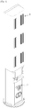
FIG. 1 is a back perspective view of an air conditioner applied with a particle sensing device according to the present disclosure; -
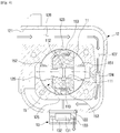
FIG. 2 is a exploded perspective view of the particle sensing device according to a first embodiment of the present disclosure; -
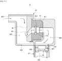
FIG. 3 andFIG. 4 are cross-section views showing motions of the particle sensing device according to the first embodiment of the present disclosure; -
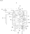
FIG. 5 is a exploded perspective view of the particle sensing device according to a second embodiment of the present disclosure; -
FIG. 6 andFIG. 7 are cross-section views showing motions of a particle sensing device according to the second embodiment of the present disclosure; -
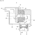
FIG. 8 andFIG. 9 are cross-section views showing motions of a particle sensing device according to a third embodiment of the present disclosure; -
FIG. 10 andFIG. 11 are cross-section views showing motions of a particle sensing device according to the a fourth embodiment of the present disclosure. - Hereinafter, a particle sensing device according to a first embodiment of the present disclosure will be described in detail with reference to accompanying drawings.
- As illustrated in
FIG. 1 , aparticle sensing device 1 is disposed in an indoor unit A of an air conditioner so that indoor air may be suctioned and concentrations of fine particles and ultrafine particles may be measured. - As illustrated in
FIGS. 2 and3 , theparticle sensing device 1 according to the first embodiment of the present disclosure includes asensor 11 for sensing a concentration of particles included in air, aflow path housing 12 in which a flow path for accommodating thesensor 11 and guiding air to thesensor 11 is formed, ablower unit 13 for discharging air to the outside after external air is suctioned into theflow path housing 12 and sensed by thesensor 11, and a flow path switching device for switching the flow path provided in theflow path housing 12 and enabling fine particles and ultrafine particles to be sensed by onesensor 11. - The flow path switching device serves to transfer all air suctioned from the outside to the
sensor 11, or to enable some of the air suctioned from the outside to flow back in an obliquely upward direction and the remaining air to be discharged. - When all air suctioned from the outside is transferred to the
sensor 11 by the flow path switching device, since all fine particles and ultrafine particles are transferred to thesensor 11, a concentration of fine particles including the ultrafine particles is sensed by thesensor 11. - In addition, while air suctioned from the outside flows downward, when only some thereof flows obliquely upward and the remaining air flows downward to be discharged to the outside by the flow path switching device, fine particles which are relatively large move downward to be discharged to the outside, however, ultrafine particles which have a property of floating upward is transferred to the
sensor 11 with some of the air flowing obliquely upward. Accordingly, a concentration of ultrafine particles is sensed by thesensor 11. - The
sensor 11 includes asensing path 111 through which air passes to be sensed, alight generator 112 which is disposed at one side of thesensing path 111 and generates light, and alight receiver 113 which is disposed at the other side of thesensing path 111 to face thelight generator 112 and receives light generated by thelight generator 112. Accordingly, with thelight generator 112 generating light and an amount of light received by thelight receiver 113 being measured, a concentration of fine particles or ultrafine particles included in air passing through thesensing path 111 is measured. - The
flow path housing 12 is formed by a pair offlow path housings suction port 121 through which external air is suctioned, andischarge port 122 through which air is discharged to the outside, afirst suction path 123 which guides all air suctioned from the outside to thesensor 11, asecond suction path 124 through which only some air suctioned from the outside is transferred to thesensor 11, abypass path 127 through which air bypasses thefirst suction path 123 to be transferred to thedischarge port 122, afirst discharge path 125 which is connected to one side of thesensing path 111 with the other side of thesensing path 111 connected to thefirst suction path 123 and guides air passing through thesensing path 111 to thedischarge port 122, and asecond discharge path 126 which is connected to one side ofsensing path 111 with the other side of thesensing path 111 connected to thesecond suction path 124 and guides air passing through thesensing path 111 to thedischarge port 122. In addition, theflow path housing 12 includes amain suction path 128 which guides air suctioned from thesuction port 121 to thefirst suction path 123 and thebypass path 127. - The
bypass path 127 extends downward to guide air downward, and thesecond suction path 124 connected to thebypass path 127 extends obliquely upward with respect to thebypass path 127 which guides air downward to enable some of the air passing through thebypass path 127 to flow obliquely upward. - The
first suction path 123 and thefirst discharge path 125 guide air to pass through thesensing path 111 in a first direction, thesecond suction path 124 and thesecond discharge path 126 guide air to pass through thesensing path 111 in a second direction. In the embodiment, the first direction and the second direction form an angle of 90°. - In the embodiment, the flow path switching device includes a
driving motor 14 which generates a rotational force to rotate thesensor 11. In the embodiment, thedriving motor 14 includes a stepping motor configured to precisely control a rotation angle of thesensor 11, and thesensing path 111 provided in thesensor 11 is connected to the first suction path and thefirst discharge path 125 or to thesecond suction path 124 and thesecond discharge path 126 as thedriving motor 14 rotates thesensor 11 by 90°. - The
flow path housing 12 includes a rotatinghousing 15 which accommodates thesensor 11 and is rotatably installed in theflow path housing 12, and thus, thesensor 11 is rotatably installed in theflow path housing 12 using the rotatinghousing 15. - The rotating
housing 15 is formed by a pair of rotatinghousings 15A and 15B which are mutually coupled from both sides of thesensor 11 and includes afirst guide 151 which guides air transferred through thefirst suction path 123 to thesensing path 111 or air passing through thesensing path 111 to thesecond discharge path 126 and asecond guide 152 which guides air transferred through thesecond suction path 124 to thesensing path 111 or guides air passing through thesensing path 111 to thefirst discharge path 125. - In addition, the rotating
housing 15 includes afirst cap 153 which closes any one of thefirst suction path 123 and thesecond discharge path 126 depending on the rotation angle of therotating housing 15 and asecond cap 154 which closes any one of thesecond suction path 124 and thefirst discharge path 125 depending on the rotation angle of therotating housing 15. - The
blower unit 13 is coupled to the above-describeddischarge port 122 and includes ablower fan 131 which includes an axial-flow fan to suction air from the direction of theflow path housing 12 through thedischarge port 122 and discharges the air to the outside, ablower motor 132 which rotates theblower fan 131, and ablower frame 133 which forms a flow path through which air flows and supports theblower motor 132. - Next, an operation of the
particle sensing device 1 formed as described above will be described with reference to the drawings. - First, as illustrated in
FIG. 3 , by rotating therotating housing 15 and thesensor 11 using thedriving motor 14, thesensing path 111 is connected to thefirst suction path 123 and thefirst discharge path 125, and thesecond suction path 124 and thesecond discharge path 126 are respectively closed by thefirst cap 153 and thesecond cap 154. - In the above state, when the
blower unit 13 is operated, external air is suctioned into theflow path housing 12 through thesuction port 121 by a suction force generated by theblower unit 13, sequentially passes through thefirst suction path 123, thesensing path 111, and thefirst discharge path 125, and is fully discharged through thedischarge port 122. - At this point, since all of the air suctioned from the outside is transferred to the
sensing path 111, thesensor 11 senses concentrations of fine particles and ultrafine particles included in air passing through thesensing path 111. - Next, as illustrated in
FIG. 4 , by rotating therotating housing 15 and thesensor 11 using thedriving motor 14, thesensing path 111 is connected to thesecond suction path 124 and thesecond discharge path 126, and thesecond suction path 124 and thefirst discharge path 125 are respectively closed by thefirst cap 153 and thesecond cap 154. - In the above state, when the
blower unit 13 is operated, external air is suctioned into the flow path housing through thesuction port 121 by a suction force generated by theblower unit 13 and is discharged through thedischarge port 122 via thebypass path 127. - In a process in which air passes through the
bypass path 127 and flows downward, some of the air passing through thebypass path 127 flows back in an obliquely upward direction through thesecond suction path 124, is transferred to thesensing path 111, and is discharged through thedischarge port 122 via thesecond discharge path 126, and all remaining air is discharged through thedischarge port 122 via thebypass path 127. - At this point, all fine particles heavier than ultrafine particles are discharged through the
discharge port 122 with air discharged throughdischarge port 122, however, since the ultrafine particles have a property of floating upward due to low weight, the ultrafine particles are included in air flowing obliquely upward through thesecond suction path 124 and pass through thesensing path 111. Since only the ultrafine particles are transferred through thesecond suction path 124, thesensor 11 senses a concentration of only ultrafine particles included in air passing through thesensing path 111. - Hereinafter, a particle sensing device according to a second embodiment of the present disclosure will be described in detail with reference to the drawings.
- As illustrated in
FIG. 5 andFIG. 6 ,aparticle sensing device 2 according to the second embodiment of the present disclosure includes asensor 21 which senses a concentration of particles included in air, aflow path housing 22 in which a flow path configured to accommodate thesensor 21 and guide air to thesensor 21 is formed, ablower unit 23 which discharges air to the outside again after external air is suctioned through theflow path housing 22 and sensed by thesensor 21, and a flow path switching device which switches a flow path provided in theflow path housing 22 and enables onesensor 21 to sense both fine particles and ultrafine particles. - The
sensor 21 includes asensing path 211 through which air passes to be sensed, alight generator 212 which is disposed at one side of thesensing path 211 and generates light, and alight receiver 213 which is disposed at the other side of thesensing path 211 to face thelight generator 212 and receives light generated by thelight generator 212. - The
flow path housing 22 is formed by a pair offlow path housings suction port 221 through which external air is suctioned, a discharge port 222 through which air is discharged to the outside, afirst suction path 261 which guides all air suctioned from the outside to thesensor 21, asecond suction path 262 through which some of the air suctioned from the outside is transferred to thesensor 21, adischarge path 225 which guides air passing through thesensing path 211 to the discharge port 222, abypass path 223 which guides air to bypass thefirst suction path 261 and guides air to the discharge port 222, and amain suction path 224 which guides air suctioned through thesuction port 221 to thefirst suction path 261 and thebypass path 223. - The
bypass path 223 extends downward to guide air downward, and thefirst suction path 261 extends obliquely downward with respect to thebypass path 223. In addition, thesecond suction path 262 extends obliquely upward with respect to thebypass path 223. In the embodiment, thefirst suction path 261 and thesecond suction path 262 are provided in a flowpath forming member 26 disposed in theflow path housing 22. - The flow path switching device includes a driving
motor 24 and adamper 25 which is rotated by the drivingmotor 24 and selectively closes any one of thefirst suction path 261 and thebypass path 223. - The
damper 25 includes afirst cap 251 which closes thefirst suction path 261, asecond cap 252 which is supported by the flowpath forming member 26 and closes a downstream side of thebypass path 223, ahinge 253 which is connected to a shaft of the drivingmotor 24 to form a rotational center of thedamper 25, a first female 254 which connects thehinge 253 and thefirst cap 251, and a second female 255 which connects thehinge 253 and thesecond cap 252 and closes thebypass path 223 with thesecond cap 252. Thefirst female 254 is provided with a throughhole 254a which enables air to pass through the first female 254 to flow even when thefirst suction path 261 is closed by thefirst cap 251. - The
blower unit 23 is coupled to the above-described discharge port 222 and includes ablower fan 231 which includes an axial-flow fan to suction air from the direction of theflow path housing 22 through the discharge port 222 and discharges the air to the outside, ablower motor 232 which rotates theblower fan 231, and ablower frame 233 which forms a flow path through which air flows and supports theblower motor 232. - A
discharge guide 27 in a pipe shape which guides air discharged through the discharge port 222 is installed in the discharge port 222, and theblower unit 23 is installed in thedischarge guide 27. - Next, an operation of the
particle sensing device 2 formed as described above will be described with reference to the drawings. - First, as illustrated in
FIG. 6 , thefirst suction path 261 is opened by rotating thedamper 25 using the drivingmotor 24, and thebypass path 223 is closed by thesecond cap 252 and thesecond female 255. - In the above state, when the
blower unit 23 is operated, external air is suctioned into theflow path housing 22 through thesuction port 221 by a suction force generated by theblower unit 23, sequentially passes through themain suction path 224, thesensing path 211, and thedischarge path 225, and is fully discharged to the outside through the discharge port 222. - At this point, since all of the air suctioned from the outside is transferred to the
sensing path 211, thesensor 21 senses concentrations of fine particles and ultrafine particles included in air passing through thesensing path 211. - Next, as illustrated in
FIG. 7 , thebypass path 223 is opened by rotating thedamper 25 using the drivingmotor 24, and thefirst suction path 261 is closed by thefirst cap 251. - In the above state, when the
blower unit 23 is operated, external air is suctioned into theflow path housing 22 through thesuction port 221 by a suction force generated by theblower unit 23, passes through themain suction path 224 and thebypass path 223, and is discharged to the outside through the discharge port 222. - In a process in which air passes through the
bypass path 223 and flows downward, some of the air flows back in an obliquely upward direction through thesecond suction path 262, is transferred to thesensing path 211, and is discharged through the discharge port 222 via thedischarge path 225, and all remaining air is discharged through the discharge port 222 via thebypass path 223. - At this point, fine particles which are heavier than ultrafine particles are discharged through the discharge port 222 intact with air discharged through the discharge port 222, however, since the ultrafine particles have a property of floating upward due to low weight, the ultrafine particles are included in air flowing obliquely upward through the
second suction path 262 and pass through thesensing path 211. Since only the ultrafine particles are transferred through thesecond suction path 262, thesensor 21 senses a concentration of only ultrafine particles included in air passing through thesensing path 211. - Hereinafter, a particle sensing device according to a third embodiment of the present disclosure will be described in detail with reference to the drawings.
- As illustrated in
FIG. 8 , aparticle sensing device 3 according to the third embodiment of the present disclosure includes asensor 31 which senses a concentration of particles included in air, aflow path housing 32 in which a flow path configured to accommodate thesensor 31 and guide air to thesensor 31 is formed, ablower unit 33 which discharges air to the outside again after external air is suctioned through theflow path housing 32 and sensed by thesensor 31 and a flow path switching device which switches a flow path provided in theflow path housing 32 and enables onesensor 31 to sense both fine particles and ultrafine particles. - The
sensor 31 includes asensing path 311 through which air passes to be sensed, alight generator 312 which is disposed at one side of thesensing path 311 and generates light, and alight receiver 313 which is disposed at the other side of thesensing path 311 to face thelight generator 312 and receives light generated by thelight generator 312. - The
flow path housing 32 includes asuction port 321 through which external air is suctioned, andischarge port 322 through which air is discharged, amain flow path 323 which connects thesuction port 321 and thedischarge port 322, and transfers all air suctioned through thesuction port 321 to thedischarge port 322, and asub-flow path 324 which guides air passing through thesensing path 311 provided in thesensor 31 to thedischarge port 322. Themain flow path 323 is vertically provided and guides air suctioned through thesuction port 321 downward, thesensing path 311 is horizontally provided, and thus, themain flow path 323 and thesensing path 311 are provided perpendicular to each other. - The flow path switching device includes a driving
motor 34 and adamper 35 which is rotatably installed in theflow path housing 32 and guides air passing through themain flow path 323 to be always transferred to at least thesensing path 311 between thedischarge port 322 and thesensing path 311, and thedamper 35 receives a rotational force from the driving motor to rotate. - The
damper 35 includes aguide path 351 which obliquely extends with respect to themain flow path 323 extending obliquely downward and guides at least some air flowing downward along themain flow path 323 to flow into thesensing path 311, acap 352 which selectively blocks air from flowing to thedamper 35 from themain flow path 323 depending on the rotation angle of thedischarge port 322. - Accordingly, as the
damper 35 rotates by 180°, theguide path 351 provided in thedamper 35 becomes inclined downward with respect to themain flow path 323 or becomes inclined upward. Thecap 352 blocks air transferred from themain flow path 323 to thedischarge port 322 from flowing in a state in which thecap 352 is inclined downward with respect to air passing through themain flow path 323. - The
blower unit 33 is coupled to the above-describeddischarge port 322 and includes ablower fan 331 which includes an axial-flow fan to suction air from the direction of theflow path housing 32 through thedischarge port 322 and discharges the air to the outside, ablower motor 332 which rotates theblower fan 331, and ablower frame 333 which forms a flow path through which air flows, and supports theblower motor 332. - A
discharge guide 37 in a pipe shape which guides air discharged through thedischarge port 322 is installed in thedischarge port 322, and theblower unit 33 is installed in thedischarge guide 37. - Next, an operation of the
particle sensing device 3 formed as described above will be described with reference to the drawings. - First, as illustrated in
FIG. 8 , by rotating thedamper 35 using the driving motor 44, theguide path 351 is disposed obliquely downward with respect to themain flow path 323, and thecap 352 blocks air transferred from themain flow path 323 to thedischarge port 322 from flowing. - In the above state, when the
blower unit 33 is operated, external air is suctioned into theflow path housing 32 through thesuction port 321 by a suction force generated by theblower unit 33, sequentially passes through themain flow path 323, theguide path 351, thesensing path 311, and thesub-flow path 324, and is fully discharged to the outside through thedischarge port 322. - At this point, since all of the air suctioned from the outside is transferred to the
sensing path 311, thesensor 31 senses concentrations of fine particles and ultrafine particles included in air passing through thesensing path 311. - Next, as illustrated in
FIG. 9 , by rotating thedamper 25 using the drivingmotor 24, theguide path 351 is disposed obliquely upward with respect to themain flow path 323, and thecap 352 does not block air transferred from themain flow path 323 to thedischarge port 322 from flowing any more. - In the above state, when the
blower unit 33 is operated, external air is suctioned into theflow path housing 32 through thesuction port 321 by a suction force generated by theblower unit 33, passes through themain flow path 323, and is discharged to the outside through thedischarge port 322. - In a process in which air passes through the
main flow path 323, some of the air flows back in an obliquely upward direction through theguide path 351, is transferred to thesensing path 311, and is discharged through thedischarge port 322 via thesub-flow path 324, and all remaining air is discharged through thedischarge port 322 via themain flow path 323 - At this point, all fine particles heavier than ultrafine particles are discharged through the
discharge port 322 with air discharged through thedischarge port 322, however, since the ultrafine particles have a property of floating due to low weight, the ultrafine particles are included in air flowing obliquely upward throughguide path 351 and pass through thesensing path 311. Accordingly, since only the ultrafine particles are transferred through thesecond suction path 324, thesensor 31 senses a concentration of only ultrafine particles included in air passing through thesensing path 311. - Hereinafter, a particle sensing device according to a fourth embodiment of the present disclosure will be described in detail with reference to the drawings.
- As illustrated in
FIG. 10 , aparticle sensing device 4 according to the fourth embodiment of the present disclosure includes asensor 41 which senses a concentration of particles included in air, aflow path housing 42 in which a flow path configured to accommodate thesensor 41 and guide air to thesensor 41 is formed, and ablower unit 43 which discharges air to the outside again after external air is suctioned through theflow path housing 42 and sensed by thesensor 41. - The
sensor 41 includes asensing path 411 through which air passes to be sensed, alight generator 412 which is disposed at one side of thesensing path 411 and generates light, and alight receiver 413 which is disposed at the other side of thesensing path 411 to face thelight generator 412 and receives light generated by thelight generator 412. - The
flow path housing 42 includes asuction port 421 through which air is suctioned, anair discharge port 422 through which air passing through thesensing path 411 is discharged, asuction path 423 which vertically extends and guides air suctioned from the outside, aguide path 451 which is split obliquely upward from thesuction path 423 and guides air to thesensing path 411, aparticle discharge port 425 provided at a lower side of thesuction path 423 to discharge particles, and adischarge path 424 which guides air passing through thesensing path 411 to theair discharge port 422. In the embodiment, theguide path 451 is provided in the flowpath forming member 45 installed in theflow path housing 42. - The
blower unit 43 is coupled to the above-describedair discharge port 422 and includes ablower fan 431 which includes an axial-flow fan to suction air from a side of theflow path housing 42 through theair discharge port 422 and discharges the air to the outside, ablower motor 432 which rotates theblower fan 431, and ablower frame 433 which forms a flow path through which air flows and supports theblower motor 432. In the embodiment, theblower unit 43 may adjust a rotational speed of theblower fan 431 such that theblower unit 43 suctions air with a first speed, and a second speed faster than the first speed. - When the
blower unit 43 suctions air at the first speed, since a suction force applied from a side of theguide path 451 is small, fine particles included in air passing through thesuction path 423 fall downward due to gravity and are discharged through theparticle discharge port 425. - On the contrary, ultrafine particles having weights lighter than that of the fine particles are suctioned into the
guide path 451 with air by a suction force applied from the side of theguide path 451, pass through thesensing path 411 and thedischarge path 424, and are discharged through theair discharge port 422. - Accordingly, the
sensor 41 senses a concentration of ultrafine particles included in air passing thesensing path 411. - In addition, as illustrated in
FIG. 11 , when theblower unit 43 suctions air at the second speed faster than the first speed, since a suction force applied from the side of theguide path 451 is great and all of the fine particles and ultrafine particles are suctioned into theguide path 451, air including the fine particles and ultrafine particles is transferred to thesensing path 411. - Accordingly, the
sensor 41 senses concentrations of fine particles and ultrafine particles included in air passing through thesensing path 411. - As is apparent from the above description, a particle sensing device and an air conditioner including the same according to one embodiment of the present disclosure can measure concentrations of fine particles and ultrafine particles using one sensor because all air is transferred to a sensor or some air flows back in an obliquely upward direction and is transferred to a sensor through a flow path switching device.
Claims (9)
- A particle sensing device (1) comprising:a sensor (11) including a sensing path (111) through which air passes; anda flow path housing (12) which accommodates the sensor (11) and guides air suctioned into the flow path housing (12) from an outside, wherein the flow path housing (12) includes:a first suction path (123) which guides air into the sensing path (111) in a first direction when connected to the sensing path (111); anda second suction path (124) which guides air, after changing flow direction inside the flow path housing, to flow in an obliquely upward second direction into the sensing path (111) when connected to the sensing path (111), andthe sensor (11) is rotatably installed and is selectively connected to one of the first suction path (123) and the second suction path (124) according to a rotation angle of the sensor (11) wherein:the first suction path is configured to guide all of the air suctioned from the outside into the sensing path based on the sensor being connected to the first suction path, andthe second suction path is configured to guide only a portion of the air suctioned from the outside into the sensing path based on the sensor being connected to the second suction path.
- The particle sensing device of claim 1, wherein the sensor includes:a light generator (112), provided at one side of the sensing path (111), to generate light; anda light receiver (113), provided at another side of the sensing path so as to face the light generator, to receive the light.
- The particle sensing device of claim 1, wherein
the flow path housing further includes:a suction port (121) through which external air is suctioned into the flow path housing;a discharge port (122) through which air is discharged to the outside. - The particle sensing device of claim 3, whereinthe flow path housing includes a bypass path (127) which extends downward, and guides air to bypass the first suction path to be discharged through the discharge port, andthe second suction path is connected to the bypass path and extends obliquely upward with respect to the bypass path.
- The particle sensing device of claim 3, further comprisinga flow path switching device including a driving motor (14) to rotate the sensor, whereinthe sensing path is connected to any one of the first suction path and the second suction path according to a rotational position of the sensor.
- The particle sensing device of claim 5, whereinthe first direction and the second direction form an angle of about 90°, androtation of the sensor by about 90° causes a suction path connected to the sensing path to change from one of the first suction path and the second suction path to the other of the first and second suction paths.
- The particle sensing device of claim 5, wherein the flow path housing further includes:a first discharge path (125) connected to the sensing path when the sensing path is connected to the first suction path; anda second discharge path (126) connected to the sensing path when the sensing path is connected to the second suction path.
- The particle sensing device of claim 7, further comprising:
a rotating housing (15) rotatably installed in the flow path housing, provided with the sensor therein, and including:a suction guide (151) which guides air suctioned into the sensing path;a discharge guide (152) which guides air discharged from the sensing path;a first cap (153) which closes any one of the first suction path and the second discharge path; anda second cap (154) which closes any one of the second suction path and the first discharge path. - An air conditioner comprising the particle sensing device (1) according to any one of the preceding claims.
Applications Claiming Priority (2)
| Application Number | Priority Date | Filing Date | Title |
|---|---|---|---|
| KR1020150087260A KR102402012B1 (en) | 2015-06-19 | 2015-06-19 | Dust sensing device and air conditioner for the same |
| PCT/KR2016/006442 WO2016204550A1 (en) | 2015-06-19 | 2016-06-17 | Particle sensing device and air conditioner including the same |
Publications (3)
| Publication Number | Publication Date |
|---|---|
| EP3271698A1 EP3271698A1 (en) | 2018-01-24 |
| EP3271698A4 EP3271698A4 (en) | 2018-05-02 |
| EP3271698B1 true EP3271698B1 (en) | 2020-09-16 |
Family
ID=57546076
Family Applications (1)
| Application Number | Title | Priority Date | Filing Date |
|---|---|---|---|
| EP16811963.4A Active EP3271698B1 (en) | 2015-06-19 | 2016-06-17 | Particle sensing device and air conditioner including the same |
Country Status (5)
| Country | Link |
|---|---|
| US (1) | US10209198B2 (en) |
| EP (1) | EP3271698B1 (en) |
| KR (1) | KR102402012B1 (en) |
| CN (1) | CN107787447B (en) |
| WO (1) | WO2016204550A1 (en) |
Families Citing this family (17)
| Publication number | Priority date | Publication date | Assignee | Title |
|---|---|---|---|---|
| US10100703B2 (en) | 2016-05-03 | 2018-10-16 | Ford Global Technologies, Llc | Method and system for exhaust particulate matter sensing |
| KR101965901B1 (en) * | 2017-06-23 | 2019-04-04 | (주)아이스퀘어 | Radiation monitoring apparatus |
| KR102132430B1 (en) * | 2018-01-23 | 2020-07-09 | 서강대학교 산학협력단 | Fog screen system |
| KR102141157B1 (en) * | 2018-01-23 | 2020-08-04 | 서강대학교 산학협력단 | Fog guide device for fog screen system |
| KR102124448B1 (en) * | 2018-08-31 | 2020-06-18 | (주) 아이스퀘어 | Radiation monitoring apparatus |
| KR102598425B1 (en) * | 2018-09-20 | 2023-11-06 | 현대자동차주식회사 | Sensor assembly for particulate matter |
| KR102156755B1 (en) * | 2018-12-26 | 2020-09-16 | 김창영 | Apparatus and system for evaluating dust removal performance of road dust cleaning vehicles |
| JP7188066B2 (en) * | 2018-12-27 | 2022-12-13 | 株式会社デンソー | Dust detector |
| KR102144973B1 (en) * | 2019-04-19 | 2020-08-14 | 주식회사 온오프시스템 | Apparatus and method for monitoring |
| KR102227457B1 (en) * | 2019-10-16 | 2021-03-15 | 쌍신전자통신주식회사 | Laser type particle sensor having multi-level light receiving element |
| KR102782037B1 (en) * | 2020-04-17 | 2025-03-13 | 엘지전자 주식회사 | Dust sensor |
| KR102345034B1 (en) * | 2020-06-15 | 2021-12-29 | 주식회사 이츠 | Indoor air quality analysis apparatus using semiconductor gas sensor |
| KR102552205B1 (en) * | 2021-11-03 | 2023-07-07 | (주)제이에스테크 | Vehicle fine dust detection sensor |
| KR20230125686A (en) * | 2022-02-21 | 2023-08-29 | 삼성전자주식회사 | Outdoor unit of air conditioner and venilation method using the same |
| US12117188B2 (en) * | 2022-05-31 | 2024-10-15 | Lennox Industries Inc. | Indoor air quality monitors for commercial HVAC systems |
| KR102448881B1 (en) * | 2022-07-13 | 2022-09-28 | 김윤수 | Particle concentration measurement method for ultra-precision electronic parts production process |
| CN116413089A (en) * | 2023-01-06 | 2023-07-11 | 无锡威孚力达催化净化器有限责任公司 | Double swirl gas intake structure for NOx concentration sensor |
Family Cites Families (24)
| Publication number | Priority date | Publication date | Assignee | Title |
|---|---|---|---|---|
| US5072626A (en) * | 1989-07-14 | 1991-12-17 | Research Triangle Institute | Measurement of ultrafine particle size distributions |
| US5825487A (en) * | 1996-10-10 | 1998-10-20 | Venturedyne, Ltd. | Particle sensor with features for setting, adjusting and trimming the flow rate of the sampled air |
| US5932795A (en) | 1997-01-22 | 1999-08-03 | President And Fellows Of Harvard College | Methods and apparatus for continuous ambient particulate mass monitoring |
| US5946091A (en) * | 1997-04-10 | 1999-08-31 | Yufa; Aleksandr L. | Method and device for precise counting and measuring the particles |
| GB2399308B (en) * | 2000-07-06 | 2005-02-09 | John Herbert North | Improved air/particle separator |
| CA2369802C (en) * | 2002-01-29 | 2007-12-18 | Centre De Recherche Industrielle Du Quebec | Particle quantifying apparatus and method |
| JP2004146568A (en) * | 2002-10-24 | 2004-05-20 | Sumitomo Electric Ind Ltd | Ceramic heater for semiconductor manufacturing equipment |
| US6796165B2 (en) * | 2002-11-18 | 2004-09-28 | Southwest Research Institute | Apparatus and method for real-time measurement of mass, size and number of solid particles of particulate matter in engine exhaust |
| US7513936B2 (en) * | 2005-05-03 | 2009-04-07 | Roques Ned J | Flat spiral capillary column assembly with thermal modulator |
| EP1924836B1 (en) * | 2005-06-28 | 2017-11-29 | Koninklijke Philips N.V. | Ultra fine particle sensor |
| JP2007057360A (en) * | 2005-08-24 | 2007-03-08 | Agilent Technol Inc | Particle detector and particle detecting method used therein |
| WO2008015851A1 (en) * | 2006-08-03 | 2008-02-07 | Sharp Kabushiki Kaisha | Air cleaner |
| JP4896899B2 (en) * | 2007-01-31 | 2012-03-14 | 東京エレクトロン株式会社 | Substrate processing apparatus and particle adhesion preventing method |
| US8047055B2 (en) | 2007-08-08 | 2011-11-01 | Tsi, Incorporated | Size segregated aerosol mass concentration measurement with inlet conditioners and multiple detectors |
| KR101003583B1 (en) | 2007-08-08 | 2010-12-22 | 웅진코웨이주식회사 | Rotating particle sensor assembly and air cleaner including the same |
| US20110226675A1 (en) | 2008-09-03 | 2011-09-22 | Bae Systems Plc | Particle separators |
| KR101063966B1 (en) * | 2009-03-23 | 2011-09-14 | 김제원 | Real time dust measuring device |
| US8481892B2 (en) * | 2009-03-30 | 2013-07-09 | Ngk Insulators, Ltd. | Ceramic heater and method for producing same |
| US8627645B2 (en) * | 2011-05-25 | 2014-01-14 | Ford Global Technologies, Llc | Emission control with a particulate matter sensor |
| WO2013047135A2 (en) * | 2011-09-27 | 2013-04-04 | シャープ株式会社 | Air purifier |
| CN203083905U (en) * | 2013-03-04 | 2013-07-24 | 南京铁道职业技术学院 | Portable PM (particulate matter)-2.5 dust particle detection instrument |
| JP5851534B2 (en) * | 2013-07-17 | 2016-02-03 | シャープ株式会社 | Fine particle measuring device |
| JP5837107B2 (en) * | 2014-01-17 | 2015-12-24 | シャープ株式会社 | Particle measuring instrument |
| KR101515858B1 (en) * | 2015-02-13 | 2015-05-04 | 주식회사 동일그린시스 | Apparatus and Method for Detecting Ultrafine Suspended Particle Matter |
-
2015
- 2015-06-19 KR KR1020150087260A patent/KR102402012B1/en active Active
-
2016
- 2016-06-17 WO PCT/KR2016/006442 patent/WO2016204550A1/en not_active Ceased
- 2016-06-17 US US15/185,512 patent/US10209198B2/en active Active
- 2016-06-17 CN CN201680035859.3A patent/CN107787447B/en active Active
- 2016-06-17 EP EP16811963.4A patent/EP3271698B1/en active Active
Non-Patent Citations (1)
| Title |
|---|
| None * |
Also Published As
| Publication number | Publication date |
|---|---|
| CN107787447B (en) | 2020-12-08 |
| EP3271698A4 (en) | 2018-05-02 |
| US10209198B2 (en) | 2019-02-19 |
| US20160370301A1 (en) | 2016-12-22 |
| KR102402012B1 (en) | 2022-05-25 |
| WO2016204550A1 (en) | 2016-12-22 |
| CN107787447A (en) | 2018-03-09 |
| EP3271698A1 (en) | 2018-01-24 |
| KR20160149724A (en) | 2016-12-28 |
Similar Documents
| Publication | Publication Date | Title |
|---|---|---|
| US10209198B2 (en) | Particle sensing device and air conditioner including the same | |
| CN107770301B (en) | Anti-falling method and anti-falling device for mobile terminal | |
| CN103379808B (en) | Electronic equipment enclosures and methods related thereto | |
| CN101801498B (en) | Rotary particle sensor assembly and air cleaner having the same | |
| CN107940058A (en) | Water pin device | |
| WO2021032875A1 (en) | Sampler device for particle concentration sensor | |
| CN106042006B (en) | Medical Robot's decelerator torque resistant structure | |
| CN204365597U (en) | Particle separating device and possess its particle assay device | |
| CN106669099A (en) | Electronic treadmill | |
| CN110650857B (en) | Air conditioner | |
| JP5805731B2 (en) | Particle separator and particle measuring instrument equipped with the same | |
| JP5318593B2 (en) | Air supply device | |
| KR100871540B1 (en) | Rotary Particle Sensor Assembly | |
| WO2022145485A1 (en) | Water supply device | |
| JP2013214412A (en) | Electric equipment with ion emitting function | |
| KR101245179B1 (en) | Flow Sensor | |
| JP5821755B2 (en) | Particle classification concentration measuring instrument | |
| KR101458109B1 (en) | Flow rate sensor | |
| CN104722140B (en) | Water film particle impactor | |
| KR102438290B1 (en) | air cleaner | |
| JP7445838B2 (en) | Outside air introduction system and structure equipped with it | |
| JP4857966B2 (en) | Ventilation equipment | |
| KR20210030141A (en) | Apparatus for processing sample and drone having the same | |
| JPH07167882A (en) | Fluid flow velocity measuring device | |
| JPWO2020246169A5 (en) |
Legal Events
| Date | Code | Title | Description |
|---|---|---|---|
| STAA | Information on the status of an ep patent application or granted ep patent |
Free format text: STATUS: THE INTERNATIONAL PUBLICATION HAS BEEN MADE |
|
| PUAI | Public reference made under article 153(3) epc to a published international application that has entered the european phase |
Free format text: ORIGINAL CODE: 0009012 |
|
| STAA | Information on the status of an ep patent application or granted ep patent |
Free format text: STATUS: REQUEST FOR EXAMINATION WAS MADE |
|
| 17P | Request for examination filed |
Effective date: 20171020 |
|
| AK | Designated contracting states |
Kind code of ref document: A1 Designated state(s): AL AT BE BG CH CY CZ DE DK EE ES FI FR GB GR HR HU IE IS IT LI LT LU LV MC MK MT NL NO PL PT RO RS SE SI SK SM TR |
|
| AX | Request for extension of the european patent |
Extension state: BA ME |
|
| STAA | Information on the status of an ep patent application or granted ep patent |
Free format text: STATUS: EXAMINATION IS IN PROGRESS |
|
| A4 | Supplementary search report drawn up and despatched |
Effective date: 20180329 |
|
| RIC1 | Information provided on ipc code assigned before grant |
Ipc: G01N 15/06 20060101AFI20180323BHEP Ipc: G01N 15/02 20060101ALI20180323BHEP Ipc: G01N 21/53 20060101ALI20180323BHEP Ipc: G01N 1/24 20060101ALI20180323BHEP Ipc: G01N 21/85 20060101ALI20180323BHEP Ipc: G01N 15/00 20060101ALI20180323BHEP Ipc: F24F 1/02 20110101ALI20180323BHEP Ipc: G01N 1/22 20060101ALI20180323BHEP |
|
| 17Q | First examination report despatched |
Effective date: 20180412 |
|
| 17Q | First examination report despatched |
Effective date: 20180418 |
|
| DAV | Request for validation of the european patent (deleted) | ||
| DAX | Request for extension of the european patent (deleted) | ||
| GRAP | Despatch of communication of intention to grant a patent |
Free format text: ORIGINAL CODE: EPIDOSNIGR1 |
|
| STAA | Information on the status of an ep patent application or granted ep patent |
Free format text: STATUS: GRANT OF PATENT IS INTENDED |
|
| INTG | Intention to grant announced |
Effective date: 20200407 |
|
| GRAJ | Information related to disapproval of communication of intention to grant by the applicant or resumption of examination proceedings by the epo deleted |
Free format text: ORIGINAL CODE: EPIDOSDIGR1 |
|
| STAA | Information on the status of an ep patent application or granted ep patent |
Free format text: STATUS: EXAMINATION IS IN PROGRESS |
|
| INTC | Intention to grant announced (deleted) | ||
| GRAR | Information related to intention to grant a patent recorded |
Free format text: ORIGINAL CODE: EPIDOSNIGR71 |
|
| GRAS | Grant fee paid |
Free format text: ORIGINAL CODE: EPIDOSNIGR3 |
|
| STAA | Information on the status of an ep patent application or granted ep patent |
Free format text: STATUS: GRANT OF PATENT IS INTENDED |
|
| GRAA | (expected) grant |
Free format text: ORIGINAL CODE: 0009210 |
|
| STAA | Information on the status of an ep patent application or granted ep patent |
Free format text: STATUS: THE PATENT HAS BEEN GRANTED |
|
| AK | Designated contracting states |
Kind code of ref document: B1 Designated state(s): AL AT BE BG CH CY CZ DE DK EE ES FI FR GB GR HR HU IE IS IT LI LT LU LV MC MK MT NL NO PL PT RO RS SE SI SK SM TR |
|
| INTG | Intention to grant announced |
Effective date: 20200811 |
|
| REG | Reference to a national code |
Ref country code: GB Ref legal event code: FG4D |
|
| REG | Reference to a national code |
Ref country code: CH Ref legal event code: EP |
|
| REG | Reference to a national code |
Ref country code: DE Ref legal event code: R096 Ref document number: 602016044219 Country of ref document: DE |
|
| REG | Reference to a national code |
Ref country code: IE Ref legal event code: FG4D |
|
| REG | Reference to a national code |
Ref country code: AT Ref legal event code: REF Ref document number: 1314590 Country of ref document: AT Kind code of ref document: T Effective date: 20201015 |
|
| PG25 | Lapsed in a contracting state [announced via postgrant information from national office to epo] |
Ref country code: GR Free format text: LAPSE BECAUSE OF FAILURE TO SUBMIT A TRANSLATION OF THE DESCRIPTION OR TO PAY THE FEE WITHIN THE PRESCRIBED TIME-LIMIT Effective date: 20201217 Ref country code: NO Free format text: LAPSE BECAUSE OF FAILURE TO SUBMIT A TRANSLATION OF THE DESCRIPTION OR TO PAY THE FEE WITHIN THE PRESCRIBED TIME-LIMIT Effective date: 20201216 Ref country code: SE Free format text: LAPSE BECAUSE OF FAILURE TO SUBMIT A TRANSLATION OF THE DESCRIPTION OR TO PAY THE FEE WITHIN THE PRESCRIBED TIME-LIMIT Effective date: 20200916 Ref country code: BG Free format text: LAPSE BECAUSE OF FAILURE TO SUBMIT A TRANSLATION OF THE DESCRIPTION OR TO PAY THE FEE WITHIN THE PRESCRIBED TIME-LIMIT Effective date: 20201216 Ref country code: FI Free format text: LAPSE BECAUSE OF FAILURE TO SUBMIT A TRANSLATION OF THE DESCRIPTION OR TO PAY THE FEE WITHIN THE PRESCRIBED TIME-LIMIT Effective date: 20200916 Ref country code: HR Free format text: LAPSE BECAUSE OF FAILURE TO SUBMIT A TRANSLATION OF THE DESCRIPTION OR TO PAY THE FEE WITHIN THE PRESCRIBED TIME-LIMIT Effective date: 20200916 |
|
| REG | Reference to a national code |
Ref country code: AT Ref legal event code: MK05 Ref document number: 1314590 Country of ref document: AT Kind code of ref document: T Effective date: 20200916 |
|
| REG | Reference to a national code |
Ref country code: NL Ref legal event code: MP Effective date: 20200916 |
|
| PG25 | Lapsed in a contracting state [announced via postgrant information from national office to epo] |
Ref country code: LV Free format text: LAPSE BECAUSE OF FAILURE TO SUBMIT A TRANSLATION OF THE DESCRIPTION OR TO PAY THE FEE WITHIN THE PRESCRIBED TIME-LIMIT Effective date: 20200916 Ref country code: RS Free format text: LAPSE BECAUSE OF FAILURE TO SUBMIT A TRANSLATION OF THE DESCRIPTION OR TO PAY THE FEE WITHIN THE PRESCRIBED TIME-LIMIT Effective date: 20200916 |
|
| REG | Reference to a national code |
Ref country code: LT Ref legal event code: MG4D |
|
| PG25 | Lapsed in a contracting state [announced via postgrant information from national office to epo] |
Ref country code: SM Free format text: LAPSE BECAUSE OF FAILURE TO SUBMIT A TRANSLATION OF THE DESCRIPTION OR TO PAY THE FEE WITHIN THE PRESCRIBED TIME-LIMIT Effective date: 20200916 Ref country code: EE Free format text: LAPSE BECAUSE OF FAILURE TO SUBMIT A TRANSLATION OF THE DESCRIPTION OR TO PAY THE FEE WITHIN THE PRESCRIBED TIME-LIMIT Effective date: 20200916 Ref country code: CZ Free format text: LAPSE BECAUSE OF FAILURE TO SUBMIT A TRANSLATION OF THE DESCRIPTION OR TO PAY THE FEE WITHIN THE PRESCRIBED TIME-LIMIT Effective date: 20200916 Ref country code: RO Free format text: LAPSE BECAUSE OF FAILURE TO SUBMIT A TRANSLATION OF THE DESCRIPTION OR TO PAY THE FEE WITHIN THE PRESCRIBED TIME-LIMIT Effective date: 20200916 Ref country code: PT Free format text: LAPSE BECAUSE OF FAILURE TO SUBMIT A TRANSLATION OF THE DESCRIPTION OR TO PAY THE FEE WITHIN THE PRESCRIBED TIME-LIMIT Effective date: 20210118 Ref country code: LT Free format text: LAPSE BECAUSE OF FAILURE TO SUBMIT A TRANSLATION OF THE DESCRIPTION OR TO PAY THE FEE WITHIN THE PRESCRIBED TIME-LIMIT Effective date: 20200916 |
|
| PG25 | Lapsed in a contracting state [announced via postgrant information from national office to epo] |
Ref country code: AL Free format text: LAPSE BECAUSE OF FAILURE TO SUBMIT A TRANSLATION OF THE DESCRIPTION OR TO PAY THE FEE WITHIN THE PRESCRIBED TIME-LIMIT Effective date: 20200916 Ref country code: AT Free format text: LAPSE BECAUSE OF FAILURE TO SUBMIT A TRANSLATION OF THE DESCRIPTION OR TO PAY THE FEE WITHIN THE PRESCRIBED TIME-LIMIT Effective date: 20200916 Ref country code: ES Free format text: LAPSE BECAUSE OF FAILURE TO SUBMIT A TRANSLATION OF THE DESCRIPTION OR TO PAY THE FEE WITHIN THE PRESCRIBED TIME-LIMIT Effective date: 20200916 Ref country code: IS Free format text: LAPSE BECAUSE OF FAILURE TO SUBMIT A TRANSLATION OF THE DESCRIPTION OR TO PAY THE FEE WITHIN THE PRESCRIBED TIME-LIMIT Effective date: 20210116 Ref country code: PL Free format text: LAPSE BECAUSE OF FAILURE TO SUBMIT A TRANSLATION OF THE DESCRIPTION OR TO PAY THE FEE WITHIN THE PRESCRIBED TIME-LIMIT Effective date: 20200916 |
|
| REG | Reference to a national code |
Ref country code: DE Ref legal event code: R097 Ref document number: 602016044219 Country of ref document: DE |
|
| PG25 | Lapsed in a contracting state [announced via postgrant information from national office to epo] |
Ref country code: SK Free format text: LAPSE BECAUSE OF FAILURE TO SUBMIT A TRANSLATION OF THE DESCRIPTION OR TO PAY THE FEE WITHIN THE PRESCRIBED TIME-LIMIT Effective date: 20200916 |
|
| PLBE | No opposition filed within time limit |
Free format text: ORIGINAL CODE: 0009261 |
|
| STAA | Information on the status of an ep patent application or granted ep patent |
Free format text: STATUS: NO OPPOSITION FILED WITHIN TIME LIMIT |
|
| 26N | No opposition filed |
Effective date: 20210617 |
|
| PG25 | Lapsed in a contracting state [announced via postgrant information from national office to epo] |
Ref country code: SI Free format text: LAPSE BECAUSE OF FAILURE TO SUBMIT A TRANSLATION OF THE DESCRIPTION OR TO PAY THE FEE WITHIN THE PRESCRIBED TIME-LIMIT Effective date: 20200916 Ref country code: DK Free format text: LAPSE BECAUSE OF FAILURE TO SUBMIT A TRANSLATION OF THE DESCRIPTION OR TO PAY THE FEE WITHIN THE PRESCRIBED TIME-LIMIT Effective date: 20200916 |
|
| PG25 | Lapsed in a contracting state [announced via postgrant information from national office to epo] |
Ref country code: IT Free format text: LAPSE BECAUSE OF FAILURE TO SUBMIT A TRANSLATION OF THE DESCRIPTION OR TO PAY THE FEE WITHIN THE PRESCRIBED TIME-LIMIT Effective date: 20200916 |
|
| PG25 | Lapsed in a contracting state [announced via postgrant information from national office to epo] |
Ref country code: MC Free format text: LAPSE BECAUSE OF FAILURE TO SUBMIT A TRANSLATION OF THE DESCRIPTION OR TO PAY THE FEE WITHIN THE PRESCRIBED TIME-LIMIT Effective date: 20200916 |
|
| REG | Reference to a national code |
Ref country code: CH Ref legal event code: PL |
|
| REG | Reference to a national code |
Ref country code: BE Ref legal event code: MM Effective date: 20210630 |
|
| PG25 | Lapsed in a contracting state [announced via postgrant information from national office to epo] |
Ref country code: LU Free format text: LAPSE BECAUSE OF NON-PAYMENT OF DUE FEES Effective date: 20210617 |
|
| PG25 | Lapsed in a contracting state [announced via postgrant information from national office to epo] |
Ref country code: LI Free format text: LAPSE BECAUSE OF NON-PAYMENT OF DUE FEES Effective date: 20210630 Ref country code: IE Free format text: LAPSE BECAUSE OF NON-PAYMENT OF DUE FEES Effective date: 20210617 Ref country code: CH Free format text: LAPSE BECAUSE OF NON-PAYMENT OF DUE FEES Effective date: 20210630 |
|
| PG25 | Lapsed in a contracting state [announced via postgrant information from national office to epo] |
Ref country code: FR Free format text: LAPSE BECAUSE OF NON-PAYMENT OF DUE FEES Effective date: 20210630 |
|
| PG25 | Lapsed in a contracting state [announced via postgrant information from national office to epo] |
Ref country code: BE Free format text: LAPSE BECAUSE OF NON-PAYMENT OF DUE FEES Effective date: 20210630 |
|
| PGFP | Annual fee paid to national office [announced via postgrant information from national office to epo] |
Ref country code: GB Payment date: 20220520 Year of fee payment: 7 |
|
| PG25 | Lapsed in a contracting state [announced via postgrant information from national office to epo] |
Ref country code: HU Free format text: LAPSE BECAUSE OF FAILURE TO SUBMIT A TRANSLATION OF THE DESCRIPTION OR TO PAY THE FEE WITHIN THE PRESCRIBED TIME-LIMIT; INVALID AB INITIO Effective date: 20160617 |
|
| PG25 | Lapsed in a contracting state [announced via postgrant information from national office to epo] |
Ref country code: NL Free format text: LAPSE BECAUSE OF NON-PAYMENT OF DUE FEES Effective date: 20200923 Ref country code: CY Free format text: LAPSE BECAUSE OF FAILURE TO SUBMIT A TRANSLATION OF THE DESCRIPTION OR TO PAY THE FEE WITHIN THE PRESCRIBED TIME-LIMIT Effective date: 20200916 |
|
| GBPC | Gb: european patent ceased through non-payment of renewal fee |
Effective date: 20230617 |
|
| PG25 | Lapsed in a contracting state [announced via postgrant information from national office to epo] |
Ref country code: MK Free format text: LAPSE BECAUSE OF FAILURE TO SUBMIT A TRANSLATION OF THE DESCRIPTION OR TO PAY THE FEE WITHIN THE PRESCRIBED TIME-LIMIT Effective date: 20200916 Ref country code: GB Free format text: LAPSE BECAUSE OF NON-PAYMENT OF DUE FEES Effective date: 20230617 |
|
| PG25 | Lapsed in a contracting state [announced via postgrant information from national office to epo] |
Ref country code: MT Free format text: LAPSE BECAUSE OF FAILURE TO SUBMIT A TRANSLATION OF THE DESCRIPTION OR TO PAY THE FEE WITHIN THE PRESCRIBED TIME-LIMIT Effective date: 20200916 |
|
| PGFP | Annual fee paid to national office [announced via postgrant information from national office to epo] |
Ref country code: DE Payment date: 20250520 Year of fee payment: 10 |
|
| PG25 | Lapsed in a contracting state [announced via postgrant information from national office to epo] |
Ref country code: TR Free format text: LAPSE BECAUSE OF FAILURE TO SUBMIT A TRANSLATION OF THE DESCRIPTION OR TO PAY THE FEE WITHIN THE PRESCRIBED TIME-LIMIT Effective date: 20200916 |