EP3271099B1 - Outillage pour l'usinage d'une gorge d'un carter de turbomachine - Google Patents
Outillage pour l'usinage d'une gorge d'un carter de turbomachine Download PDFInfo
- Publication number
- EP3271099B1 EP3271099B1 EP16714486.4A EP16714486A EP3271099B1 EP 3271099 B1 EP3271099 B1 EP 3271099B1 EP 16714486 A EP16714486 A EP 16714486A EP 3271099 B1 EP3271099 B1 EP 3271099B1
- Authority
- EP
- European Patent Office
- Prior art keywords
- groove
- positioning
- casing
- tooling
- baseplate
- Prior art date
- Legal status (The legal status is an assumption and is not a legal conclusion. Google has not performed a legal analysis and makes no representation as to the accuracy of the status listed.)
- Active
Links
Images


Classifications
-
- B—PERFORMING OPERATIONS; TRANSPORTING
- B23—MACHINE TOOLS; METAL-WORKING NOT OTHERWISE PROVIDED FOR
- B23C—MILLING
- B23C3/00—Milling particular work; Special milling operations; Machines therefor
- B23C3/28—Grooving workpieces
- B23C3/34—Milling grooves of other forms, e.g. circumferential
-
- B—PERFORMING OPERATIONS; TRANSPORTING
- B23—MACHINE TOOLS; METAL-WORKING NOT OTHERWISE PROVIDED FOR
- B23B—TURNING; BORING
- B23B3/00—General-purpose turning-machines or devices, e.g. centre lathes with feed rod and lead screw; Sets of turning-machines
- B23B3/22—Turning-machines or devices with rotary tool heads
- B23B3/26—Turning-machines or devices with rotary tool heads the tools of which perform a radial movement; Rotary tool heads thereof
-
- B—PERFORMING OPERATIONS; TRANSPORTING
- B23—MACHINE TOOLS; METAL-WORKING NOT OTHERWISE PROVIDED FOR
- B23C—MILLING
- B23C3/00—Milling particular work; Special milling operations; Machines therefor
- B23C3/16—Working surfaces curved in two directions
- B23C3/18—Working surfaces curved in two directions for shaping screw-propellers, turbine blades, or impellers
-
- F—MECHANICAL ENGINEERING; LIGHTING; HEATING; WEAPONS; BLASTING
- F01—MACHINES OR ENGINES IN GENERAL; ENGINE PLANTS IN GENERAL; STEAM ENGINES
- F01D—NON-POSITIVE DISPLACEMENT MACHINES OR ENGINES, e.g. STEAM TURBINES
- F01D25/00—Component parts, details, or accessories, not provided for in, or of interest apart from, other groups
- F01D25/28—Supporting or mounting arrangements, e.g. for turbine casing
- F01D25/285—Temporary support structures, e.g. for testing, assembling, installing, repairing; Assembly methods using such structures
-
- B—PERFORMING OPERATIONS; TRANSPORTING
- B23—MACHINE TOOLS; METAL-WORKING NOT OTHERWISE PROVIDED FOR
- B23C—MILLING
- B23C2215/00—Details of workpieces
- B23C2215/04—Aircraft components
-
- B—PERFORMING OPERATIONS; TRANSPORTING
- B23—MACHINE TOOLS; METAL-WORKING NOT OTHERWISE PROVIDED FOR
- B23C—MILLING
- B23C2220/00—Details of milling processes
- B23C2220/36—Production of grooves
-
- F—MECHANICAL ENGINEERING; LIGHTING; HEATING; WEAPONS; BLASTING
- F05—INDEXING SCHEMES RELATING TO ENGINES OR PUMPS IN VARIOUS SUBCLASSES OF CLASSES F01-F04
- F05D—INDEXING SCHEME FOR ASPECTS RELATING TO NON-POSITIVE-DISPLACEMENT MACHINES OR ENGINES, GAS-TURBINES OR JET-PROPULSION PLANTS
- F05D2230/00—Manufacture
- F05D2230/10—Manufacture by removing material
Definitions
- the invention relates to a tool for machining an annular groove of a turbomachine casing and a method of machining such a groove.
- a turbomachine conventionally comprises an intermediate casing comprising a shell, called the intermediate casing shell, intended to provide the interface between the intermediate casing of the turbojet engine and the thrust reverser covers of the nacelle.
- the document US 2011/083537 A1 shows a tool having the features of the preamble of claim 1.
- An example of intermediate housing shell is described for example in the document FR 2 925 120 .
- the intermediate casing shell comprises an annular groove which is intended to receive a complementary annular lip belonging to the thrust reverser covers.
- the lip is supported radially and / or axially against the inner faces of the groove.
- the direction and amplitude of the support forces vary according to the operating conditions of the turbojet engine.
- the ferrule supports the thrust reverser cover, the lip thus bears radially down against the bottom of the groove.
- the lip is supported axially in one direction against a wall of the groove and radially against the bottom of the groove.
- turbojet generates vibrations which result in a relative displacement between the lip and the groove.
- the invention proposes a tool for machining worn areas for repair directly under the wing of an aircraft, that is to say without disassembly of the engine.
- the invention relates to a tool for machining an annular groove of a turbomachine casing, with the features of claim 1.
- Such tooling makes it possible to accurately position the machining tool with respect to the groove, thanks to the various positioning means, and to then be able to precisely machine each worn zone, without requiring disassembly of the motor.
- Such machining can thus be achieved by zones and under the wing of an aircraft. This avoids complete disassembly of the engine and a complete replacement of the intermediate casing shell.
- an anti-wear strip for example can then be bonded to each machined area, such anti-wear strip being made of resin and having fibers.
- Another solution is for example to apply a layer of resin and a solution for lubricating the repaired area.
- the first positioning means comprise a micrometric ring adapted to adapt the position of the machining tool according to the first axis, by rotation of the ring.
- a ring allows precise radial positioning of the machining tool with respect to the groove.
- the second positioning means comprise a micrometer table comprising a support movable along the second axis relative to the base, the machining tool being mounted on the movable support.
- a micrometer table allows precise axial positioning of the machining tool with respect to the groove.
- the machining tool can be mounted on the movable support by means of the first positioning means.
- the third positioning means comprise at least one support zone of the base, adapted to engage and / or press radially and axially by complementarity of shape on annular flanks, for example radial flanks. , defining the throat of the casing of the turbomachine.
- the machining tool may be a milling tool.
- the first positioning means may be able to position the machining tool radially relative to the base with a tolerance of less than 0.05 mm, preferably less than 0.025 mm, the second positioning means being able to be positioned axially the machining tool relative to the base with a tolerance of less than 0.1 mm, preferably less than 0.05 mm.
- the tooling comprises pressing means adapted to maintain the base resting on the housing.
- pressing means adapted to maintain the base resting on the housing.
- the pressing means may comprise at least one roller and elastic return means tending to maintain said roller on the housing, facing said groove and the base.
- the invention thus proposes a simple machining method making it possible to machine only the worn out areas of the groove, without disassembling the engine and directly under the wing of the aircraft.
- the step of mounting the tool on the casing comprises a step of radial and axial positioning of the machining tool relative to said groove, using the first, second and third positioning means.
- Said positioning step may comprise a step of determining the difference in size between the worn zone and a healthy zone of the groove.
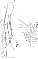
- FIG. 1 an aircraft turbojet engine 1 having a nacelle 2, a fan casing 3, extended rearwardly by an intermediate casing 4.
- the intermediate casing 4 comprises a radially outer shell 5 located in the rear aerodynamic extension of the fan casing 3 and transverse flanges 6 disposed radially inwardly relative to this outer shell 5.
- the intermediate casing 4 further comprises structural arms 7 distributed angularly. and extending radially between the flanges 6, to the outer shell 5 with which they come into contact.
- the outer shell 5 of the intermediate casing 4 comprises, in its downstream part, a part of revolution 8, the main purpose of which is to establish a connection between the outer shell 5 and the nacelle hoods directly adjacent downstream.
- the nacelle 2 forms a continuous aerodynamic external surface consisting of an air inlet 9, fan hoods 10, thrust reverser hoods 11, and a fixed rear hood 12, these elements being arranged adjacent to each other. 'front to back.
- the thrust reverser covers delimit in known manner an annular channel of secondary flow 13, thanks to external annular skins 14 and internal 15.
- connection between the revolution portion 8 of the casing and the thrust reverser cowls 11 is formed by means of an annular groove 16 made in the revolution portion 8 and an annular lip 17 which is mounted on a supporting structure 18 of the covers 11, which is received in the groove 16.
- An annular seal 19 is arranged between the groove 16 and the lip 17 to prevent any air circulation at the junction between the part of revolution 8 and the carrier structure 18.
- the axial section of the groove 16 is generally U-shaped, the groove 16 thus comprises a front face 20 of revolution, a rear face 21 of revolution facing the front face 20 and a cylindrical bottom face 22 connecting the front faces. and rear 20, 21 at their inner radial ends.
- the annular lip 17 is received in the groove 16 and bears axially and / or radially against the faces 20, 21, 22 of the groove 16.
- the revolution portion 8 is made of aluminum-based material, which wears quickly.
- the invention proposes a tool 24 shown in FIGS. Figures 3 to 6 .
- This comprises a machining tool 25 in the form of a milling machine whose milling cutter rotates about a radial axis Y, perpendicular to the longitudinal axis X of the turbomachine 1.
- Said milling machine 25 is, for example, pneumatic type and is connected to a pipe 26 for supplying compressed air ( figure 5 ).
- the fixed part of said machining tool 25 is fixed at its radially inner end to a plate 27 in the form of a ring, via a micrometer ring 28.
- the milling cutter of the machining tool 25 is therefore movable radially, to a certain extent, relative to the plate 27.
- the pivoting of the ring 28 around the Y axis makes it possible to adjust the position of the milling cutter of the machining tool 25.
- the radial position of the cutter can be adjusted with a tolerance of less than 0.05 mm, preferably less than 0.025 mm.
- the plate 27 is fixed on a support 29 of a micrometer table 30.
- the latter further comprises a frame 31, the support 29 being movable along the axis X with respect to the frame 31.
- the displacement of the mobile support 29 is actuated by a micrometric screw 32.
- the axial position of the support 29, and therefore of the cutter can thus be adjusted with a tolerance of less than 0.1 mm, preferably less than 0.05 mm.
- the frame 31 is fixed on the radially outer face of a base 33.
- Said base 33 further comprises two grooves 34 ( figures 5 and 6 ) extending circumferentially, that is to say perpendicularly to the X and Y axes, and opening radially inwards.
- Said grooves 34 have shapes complementary to the flanks 35 delimiting the groove 16 of the shell 5 of the intermediate casing 4 and delimit between them a projecting portion 36 intended to be engaged in the groove 16 of the shell 5.
- the surfaces of said grooves 34 are intended to bear on the surfaces 37 of the sidewalls 35, opposite the surfaces 20, 21 delimiting the groove 16, and / or on the radially outer ends 38 of the sidewalls 35.
- Said base 33 is also equipped with a hollow handle 39 used for the suction of chips generated during machining, connected to a suction pipe not shown.
- the base 33 is also equipped with blowing means 40 ( figure 3 ) arranged facing the suction means 39, so as to direct the chips to said suction means 39.
- the blowing means 40 comprise a blowing nozzle connected at 41 to an auxiliary line for supplying compressed air (no shown).
- the tooling 24 further comprises a base 42 extending radially, fixed to the base 33, a roller 43 being mounted on said base 42, facing the base 33, said roller 43 being mounted on a yoke 44, itself attached to the end of one or more movable rods 45, said rods 45 and the roller 43 being biased radially outwards, that is to say in the direction of the base 33, by the intermediate resilient biasing means comprising a helical compression spring 46.
- the tooling 24 is mounted by an operator on the shell 5.
- the projecting portion 36 of the base 33 is engaged in the groove 16 of the shell 5 and the flanks 35 are engaged in the grooves 34 of the base 33.
- the roller 43 is applied, via the spring 46, on the radially inner surface of the ferrule 5, facing the groove 16.
- the radially outer ends 38 of the flanks 35 can then bear against the bottoms of the grooves 34 of the base 33, immobilizing it radially relative to the shell 5.
- the surfaces of the grooves 34 of the base 33 are supported on the surfaces 37 of the sidewalls 35, so that the base 33 is also axially immobilized relative to the ferrule.
- radial and axial positioning can be achieved by only pressing the surfaces of the grooves 34 on the surfaces 37 of the shell 5, the ends 38 of the flanks 35. not then bearing against the bottom of the throats 34.
- the operator rotates the micrometer ring 28.
- the operator rotates the micrometer screw 32 of the micrometer table 30, so as to move the support 29.
- the operator can measure wear of the worn part using a comparator type tool. For this, if the groove is too deteriorated, then it is reconstructed, at least in part, using additional metal parts, then the thickness of a healthy part of the groove is used as a reference for the comparator. In other words, the comparator is positioned on a healthy part of the throat to tare it. The comparator is then mounted on a worn portion of the groove to determine the thickness difference between the healthy portion and the worn portion of the groove. The position of the cutter is then adapted accordingly.
- the milling tool 25 can then be started and the tooling 24 can be moved circumferentially, using the handle 39, along the used zone 23 of the groove 16 of the ferrule 5, so that the cutter can machine the worn areas of the surfaces 20, 21, 22.
- the figure 6 represents a worn zone 23 of the groove which has been partially machined.
- the already machined part is referenced 48 in this figure.
- the invention thus proposes a tool 24 and a machining method for machining the only worn areas 23 of the groove 16 of the shell 5, directly under the wing of the aircraft.
Landscapes
- Engineering & Computer Science (AREA)
- Mechanical Engineering (AREA)
- General Engineering & Computer Science (AREA)
- Structures Of Non-Positive Displacement Pumps (AREA)
- Milling Processes (AREA)
- Turbine Rotor Nozzle Sealing (AREA)
- Jigs For Machine Tools (AREA)
Description
- L'invention concerne un outillage pour l'usinage d'une gorge annulaire d'un carter de turbomachine ainsi qu'un procédé d'usinage d'une telle gorge.
- Une turbomachine comporte classiquement un carter intermédiaire comprenant une virole, appelée virole de carter intermédiaire, destinée à réaliser l'interface entre le carter intermédiaire du turboréacteur et des capots d'inverseur de poussée de la nacelle.
- Le document
US 2011/083537 A1 montre un outillage présentant les caractéristiques du préambule de la revendication 1. Un exemple de virole de carter intermédiaire est décrit par exemple dans le documentFR 2 925 120 - La virole de carter intermédiaire comporte une gorge annulaire qui est destinée à recevoir une lèvre annulaire complémentaire appartenant aux capots d'inverseur de poussée. La lèvre s'appuie radialement et/ou axialement contre les faces internes de la gorge.
- Pendant le fonctionnement du turboréacteur, la direction et l'amplitude des efforts d'appui varient selon les conditions de fonctionnement du turboréacteur.
- Ainsi, par exemple, lorsque le turboréacteur est à l'arrêt, la virole supporte le capot d'inverseur de poussée, la lèvre s'appuie donc radialement vers le bas contre le fond de la gorge.
- A l'inverse, lors de l'inversion de poussée, la lèvre s'appuie axialement dans un sens contre une paroi de la gorge et radialement contre le fond de la gorge.
- Aussi, le turboréacteur produit des vibrations qui résultent en un déplacement relatif entre la lèvre et la gorge.
- Toutes ces contraintes et vibrations génèrent une usure des parois de la gorge. Cette usure est répartie irrégulièrement sur la périphérie de la gorge.
- Lorsque cette usure devient supérieure à une limite prédéfinie, qui est de l'ordre de quelques dixièmes de millimètres, la gorge doit être réparée. A défaut de procédé de réparation existant, la virole est remplacée, ce qui impose un démontage complet du moteur, une telle opération étant longue et coûteuse.
- L'invention propose un outillage permettant d'usiner les zones usées en vue de leur réparation, directement sous l'aile d'un avion, c'est-à-dire sans démontage du moteur.
- A cet effet, l'invention concerne un outillage pour l'usinage d'une gorge annulaire d'un carter de turbomachine, avec les caractéristiques de la revendication 1.
- Un tel outillage permet de positionner précisément l'outil d'usinage vis-à-vis de la gorge, grâce aux différents moyens de positionnement, et de pouvoir ensuite usiner précisément chaque zone usée, sans nécessiter de démontage du moteur. Un tel usinage peut ainsi être réalisé par zones et sous l'aile d'un avion. On évite ainsi un démontage complet du moteur ainsi qu'un remplacement complet de la virole de carter intermédiaire. Après usinage des différentes zones usées, une bande anti-usure par exemple peut ensuite être collée sur chaque zone usinée, une telle bande anti-usure étant réalisée à base de résine et comportant des fibres. Une autre solution est par exemple d'appliquer une couche de résine ainsi qu'une solution permettant de lubrifier la zone réparée.
- De préférence, les premiers moyens de positionnement comportent une bague micrométrique apte à adapter la position de l'outil d'usinage selon le premier axe, par rotation de la bague. Une telle bague permet un positionnement radial précis de l'outil d'usinage par rapport à la gorge.
- Par ailleurs, les deuxièmes moyens de positionnement comportent une table micrométrique comprenant un support mobile selon le second axe par rapport à l'embase, l'outil d'usinage étant monté sur le support mobile. L'utilisation d'une table micrométrique permet un positionnement axial précis de l'outil d'usinage par rapport à la gorge.
- Dans ce cas, l'outil d'usinage peut être monté sur le support mobile par l'intermédiaire des premiers moyens de positionnement.
- De plus, les troisièmes moyens de positionnement comportent au moins une zone d'appui de l'embase, aptes à venir s'engager et/ou s'appuyer radialement et axialement par complémentarité de forme sur des flancs annulaires, par exemple des flancs radiaux, délimitant la gorge du carter de la turbomachine.
- Selon une caractéristique de l'invention, l'outil d'usinage peut être un outil de fraisage.
- Les premiers moyens de positionnement peuvent être aptes à positionner radialement l'outil d'usinage par rapport à l'embase avec une tolérance inférieure à 0,05 mm, de préférence inférieure à 0,025 mm, les seconds moyens de positionnement pouvant être aptes à positionner axialement l'outil d'usinage par rapport à l'embase avec une tolérance inférieure à 0,1 mm, de préférence inférieure à 0,05 mm.
- En outre, l'outillage comporte des moyens presseurs aptes à maintenir l'embase en appui sur le carter. Une telle caractéristique permet de maintenir le bon positionnement de l'embase, et donc de l'outil d'usinage, par rapport à la gorge.
- Dans ce cas, les moyens presseurs peuvent comporter au moins un galet et des moyens de rappel élastiques tendant à maintenir ledit galet sur le carter, en regard de ladite gorge et de l'embase.
- L'invention comporte également un procédé d'usinage d'une gorge annulaire d'un carter de turbomachine, par exemple d'un carter intermédiaire de turbomachine, comportant les étapes consistant à :
- identifier une zone usée de ladite gorge,
- monter un outillage selon l'invention sur ledit carter de façon à ce que l'embase soit montée sur ladite gorge par l'intermédiaire des troisièmes moyens de positionnement, au niveau de ladite zone usée,
- usiner au moins une partie de ladite zone usée de la gorge par déplacement de l'outillage le long de ladite zone usée.
- L'invention propose ainsi un procédé d'usinage simple permettant d'usiner uniquement les zones usées de la gorge, sans démontage du moteur et directement sous l'aile de l'avion.
- De préférence, l'étape de montage de l'outillage sur le carter comporte une étape de positionnement radial et axial de l'outil d'usinage par rapport à ladite gorge, à l'aide des premiers, deuxièmes et troisièmes moyens de positionnement.
- Ladite étape de positionnement peut comporter une étape de détermination de la différence de dimension entre la zone usée et une zone saine de la gorge.
- L'invention sera mieux comprise et d'autres détails, caractéristiques et avantages de l'invention apparaîtront à la lecture de la description suivante faite à titre d'exemple non limitatif en référence aux dessins annexés dans lesquels :
- la
figure 1 est une représentation schématique en section axiale partielle d'un turboréacteur d'aéronef, - la
figure 2 est un détail à plus grande échelle du turboréacteur représenté à lafigure 1 , montrant la liaison entre la partie de révolution de carter et les capots d'inverseur de poussée, - la
figure 3 est une vue en perspective de l'outillage selon l'invention, - la
figure 4 est une vue de face de l'outillage, - la
figure 5 est une vue en perspective de l'outillage et de la virole de carter intermédiaire, l'outillage étant monté au niveau de la gorge de la virole, - la
figure 6 est une vue illustrant une zone usée de la gorge qui est partiellement usinée, l'embase de l'outillage étant montée sur la gorge. - On a représenté à la
figure 1 , un turboréacteur 1 d'aéronef comportant une nacelle 2, un carter de soufflante 3, prolongé vers l'arrière par un carter intermédiaire 4. - Le carter intermédiaire 4 comprend une virole radialement externe 5 située dans le prolongement aérodynamique arrière du carter de soufflante 3 et des flasques transversaux 6 disposés radialement intérieurement par rapport à cette virole extérieure 5. Le carter intermédiaire 4 comprend en outre des bras structuraux 7 répartis angulairement et s'étendant radialement entre les flasques 6, jusqu'à la virole extérieure 5 avec laquelle ils viennent en contact.
- La virole extérieure 5 du carter intermédiaire 4 comporte, dans sa partie aval, une partie de révolution 8, dont le but principal est d'établir une liaison entre la virole extérieure 5 et les capots de nacelle directement adjacents vers l'aval.
- La nacelle 2 forme une surface extérieure aérodynamique continue, constituée par une entrée d'air 9, des capots de soufflante 10, des capots d'inverseur de poussée 11, et un capotage arrière fixe 12, ces éléments étant agencés de façon adjacente de l'avant vers l'arrière.
- Les capots d'inverseur de poussée 11, généralement au nombre de deux et articulés sur la structure rigide du mât, délimitent de façon connue un canal annulaire de flux secondaire 13, grâce à des peaux annulaires externe 14 et interne 15.
- Comme on peut le voir plus en détails à la
figure 2 , la liaison entre la partie de révolution 8 du carter et les capots 11 d'inverseur de poussée est réalisée par l'intermédiaire d'une gorge annulaire 16 réalisée dans la partie de révolution 8 et d'une lèvre annulaire 17 qui est montée sur une structure porteuse 18 des capots 11, qui est reçue dans la gorge 16. - Cette coopération de la lèvre annulaire 17 avec la gorge 16 permet le maintien axial et radial des capots 11 d'inverseur sur la nacelle 2.
- Un joint annulaire 19 est agencé entre la gorge 16 et la lèvre 17 pour empêcher toute circulation d'air au niveau de la jonction entre la partie de révolution 8 et la structure porteuse 18.
- La section axiale de la gorge 16 est globalement en forme de U, la gorge 16 comporte ainsi une face avant 20 de révolution, une face arrière 21 de révolution faisant face à la face avant 20 et une face de fond 22 cylindrique reliant les faces avant et arrière 20, 21 à leurs extrémités radiales internes.
- La lèvre annulaire 17 est reçue dans la gorge 16 et s'appuie axialement et/ou radialement contre les faces 20, 21, 22 de la gorge 16.
- Lors du fonctionnement du turboréacteur 1, les vibrations provoquées par les parties en mouvement provoquent un mouvement de la lèvre 17 dans la gorge 16, et donc une usure progressive des faces 20, 21, 22 de la gorge 16.
- Afin de limiter le poids général du turboréacteur, la partie de révolution 8 est réalisée en matériau à base d'aluminium, qui s'use rapidement.
- Si l'usure des faces 20, 21, 22 de la gorge 16 est trop prononcée, un jeu important se forme entre la lèvre 17 et la gorge 16.
- Afin de pouvoir réparer lesdites surfaces 20, 21, 22, il convient tout d'abord d'usiner les zones usées 23 (
figure 6 ) de ces surfaces 20, 21, 22 avant par exemple de coller une bande anti-usure sur chaque zone usinée, une telle bande anti-usure étant réalisée par exemple à base de résine et comportant des fibres. Une autre solution est par exemple d'appliquer sur chaque zone usinée une couche de résine ainsi qu'une solution permettant de lubrifier la zone réparée. - Afin de réaliser l'usinage des différentes zones usées directement sous l'aile d'un avion, c'est-à-dire sans dépose et/ou démontage complet du moteur 1, l'invention propose un outillage 24 représenté aux
figures 3 à 6 . - Celui-ci comporte un outil d'usinage 25 se présentant sous la forme d'une fraiseuse dont la fraise tourne autour d'un axe radial Y, perpendiculaire à l'axe longitudinal X de la turbomachine 1. Ladite fraiseuse 25 est par exemple de type pneumatique et est raccordée à une conduite 26 d'alimentation en air comprimé (
figure 5 ). - La partie fixe dudit outil d'usinage 25 est fixée à son extrémité radialement interne sur une platine 27 en forme d'anneau, par l'intermédiaire d'une bague micrométrique 28. La fraise de l'outil d'usinage 25 est donc mobile radialement, dans une certaine mesure, par rapport à la platine 27. Le pivotement de la bague 28 autour de l'axe Y permet d'ajuster la position de la fraise de l'outil d'usinage 25.
- La position radiale de la fraise peut être ajustée avec une tolérance inférieure à 0,05 mm, de préférence inférieure à 0,025 mm.
- La platine 27 est fixée sur un support 29 d'une table micrométrique 30. Cette dernière comporte en outre un cadre 31, le support 29 étant mobile selon l'axe X par rapport au cadre 31. Le déplacement du support mobile 29 est actionné par une vis micrométrique 32. La position axiale du support 29, et donc de la fraise, peut ainsi être ajustée avec une tolérance inférieure à 0,1 mm, de préférence inférieure à 0,05 mm.
- Le cadre 31 est fixé sur la face radialement externe d'une embase 33. Ladite embase 33 comporte en outre deux gorges 34 (
figures 5 et6 ) s'étendant circonférentiellement, c'est-à-dire perpendiculairement aux axes X et Y, et débouchant radialement vers l'intérieur. Lesdites gorges 34 ont des formes complémentaires aux flancs 35 délimitant la gorge 16 de la virole 5 du carter intermédiaire 4 et délimitent entre elles une partie en saillie 36 destinée à être engagée dans la gorge 16 de la virole 5. - Plus particulièrement, les surfaces desdites gorges 34 sont destinées à prendre appui sur les surfaces 37 des flancs 35, opposées aux surfaces 20, 21 délimitant la gorge 16, et/ou sur les extrémités radialement externes 38 des flancs 35.
- Ladite embase 33 est également équipée d'une poignée creuse 39 servant à l'aspiration des copeaux générés lors de l'usinage, raccordée à une conduite d'aspiration non représentée. L'embase 33 est également équipée de moyens de soufflage 40 (
figure 3 ) agencés en regard des moyens d'aspiration 39, de manière à diriger les copeaux vers lesdits moyens d'aspiration 39. Les moyens de soufflage 40 comportent une buse de soufflage raccordée en 41 à une conduite auxiliaire d'alimentation en air comprimé (non représentée). - L'outillage 24 comporte en outre un socle 42 s'étendant radialement, fixé à l'embase 33, un galet 43 étant monté sur ledit socle 42, en regard de l'embase 33, ledit galet 43 étant monté sur une chape 44, elle-même fixée à l'extrémité d'une ou plusieurs tiges mobiles 45, lesdites tiges 45 et le galet 43 étant rappelés radialement vers l'extérieur, c'est-à-dire en direction de l'embase 33, par l'intermédiaire de moyens de rappels élastiques comprenant un ressort hélicoïdal de compression 46.
- Afin d'usiner une ou plusieurs zones usées 23, c'est-à-dire un ou plusieurs secteurs angulaires de la gorge 16 de la virole 5 du carter intermédiaire 4, il est procédé comme suit.
- Tout d'abord, après ouverture des capots 11 d'inverseur de poussée de la nacelle 2, l'outillage 24 est monté par un opérateur sur la virole 5. En particulier, la partie en saillie 36 de l'embase 33 est engagée dans la gorge 16 de la virole 5 et les flancs 35 sont engagés dans les gorges 34 de l'embase 33.
- Le galet 43 est appliqué, par l'intermédiaire du ressort 46, sur la surface radialement interne de la virole 5, en regard de la rainure 16. Les extrémités radialement externes 38 des flancs 35 peuvent alors être en appui sur les fonds des gorges 34 de l'embase 33, immobilisant celle-ci radialement par rapport à la virole 5. Par ailleurs, les surfaces des gorges 34 de l'embase 33 sont en appui sur les surfaces 37 des flancs 35, de sorte que l'embase 33 est également immobilisée axialement par rapport à la virole. En fonction de la forme des surfaces 37 (par exemple forme en congés ou forme tronconique), le positionnement radial et axial peut être réalisé par seul appui des surfaces des gorges 34 sur les surfaces 37 de la virole 5, les extrémités 38 des flancs 35 ne venant alors pas en appui contre le fond des gorges 34.
- Afin d'ajuster précisément la position radiale de la fraise, par rapport à une référence non usée et accessible de la virole 5, par exemple la zone référencée 47 à la
figure 2 , l'opérateur fait pivoter la bague micrométrique 28. Par ailleurs, afin d'ajuster précisément la position axiale de la fraise, par rapport à ladite référence 47 de la virole 5, l'opérateur fait pivoter la vis micrométrique 32 de la table micrométrique 30, de manière à déplacer le support 29. - A cet effet, l'opérateur peut mesurer l'usure de la partie usée à l'aide d'un outil de type comparateur. Pour cela, si la gorge est trop détériorée, alors celle-ci est reconstruite, au moins en partie, à l'aide de pièces métalliques additionnelles, puis l'épaisseur d'une partie saine de la gorge est utilisée en tant que référence pour le comparateur. En d'autres termes, le comparateur est positionné sur une partie saine de la gorge afin de le tarer. Le comparateur est ensuite monté sur une partie usée de la gorge afin de déterminer l'écart d'épaisseur entre la partie saine et la partie usée de la gorge. La position de la fraise est alors adaptée en conséquence.
- L'outil de fraisage 25 peut ensuite être démarré et l'outillage 24 peut être déplacé circonférentiellement, à l'aide de la poignée 39, le long de la zone usée 23 de la gorge 16 de la virole 5, de façon à ce que la fraise puisse usiner les zones usées des surfaces 20, 21, 22.
- La
figure 6 représente une zone usée 23 de la gorge qui a été partiellement usinée. La partie déjà usinée est référencée 48 sur cette figure. - L'invention propose ainsi un outillage 24 et un procédé d'usinage permettant l'usinage des seules zones usées 23 de la gorge 16 de la virole 5, directement sous l'aile de l'avion.
Claims (9)
- Outillage (24) pour l'usinage d'une gorge annulaire (16) d'un carter annulaire (4) de turbomachine (1), ledit outillage (24) comportant un outil d'usinage (25), une embase (33), des premiers moyens de positionnement (28) de l'outil d'usinage (25) par rapport à l'embase (33) selon un premier axe (Y) formant un axe radial, des deuxièmes moyens de positionnement (30) de l'outil d'usinage (25) par rapport à l'embase (33) selon un second axe (X) perpendiculaire au premier axe (Y), ledit second axe (X) s'étendant selon l'axe de la gorge (16) et du carter annulaires, et des troisièmes moyens de positionnement (34), aptes à positionner axialement et radialement l'embase (33) par rapport à la gorge (16, 37) du carter (4), caractérisé en ce que lesdits troisièmes moyens de positionnement comportant au moins une zone d'appui (34) de l'embase (33), aptes à venir s'engager et/ou s'appuyer radialement et axialement par complémentarité de forme sur des flancs annulaires, par exemple des flancs radiaux (35), délimitant la gorge (16) du carter (4) de la turbomachine (1), l'outillage comportant en outre des moyens presseurs (42, 43, 44, 45, 46) aptes à maintenir l'embase (33) en appui sur le carter (4).
- Outillage (24) selon la revendication 1, caractérisé en ce que les premiers moyens de positionnement comportent une bague micrométrique (28) apte à adapter la position de l'outil d'usinage (25) selon le premier axe (Y), par rotation de la bague (28).
- Outillage (24) selon la revendication 1 ou 2, caractérisé en ce que les deuxièmes moyens de positionnement comportent une table micrométrique (30) comprenant un support (31) mobile selon le second axe (X) par rapport à l'embase (33), l'outil d'usinage (25) étant monté sur le support mobile (31).
- Outillage (24) selon la revendication 3, caractérisé en ce que l'outil d'usinage (25) est monté sur le support mobile (31) par l'intermédiaire des premiers moyens de positionnement (28).
- Outillage (24) selon l'une des revendications 1 à 4, caractérisé en ce que l'outil d'usinage (25) est un outil de fraisage.
- Outillage (24) selon l'une des revendications 1 à 5, caractérisé en ce que les premiers moyens de positionnement (28) sont aptes à positionner radialement l'outil d'usinage (25) par rapport à l'embase (33) avec une tolérance inférieure à 0,05 mm, de préférence inférieure à 0,025 mm et/ou les seconds moyens de positionnement (30) sont aptes à positionner axialement l'outil d'usinage (25) par rapport à l'embase (33) avec une tolérance inférieure à 0,1 mm, de préférence inférieure à 0,05 mm.
- Outillage (24) selon l'une des revendications 1 à 6, caractérisé en ce que les moyens presseurs comportent au moins un galet (43) et des moyens de rappel élastiques (46) tendant à maintenir ledit galet (43) sur le carter (4), en regard de ladite gorge (16) et de l'embase (33).
- Procédé d'usinage d'une gorge annulaire (16) d'un carter annulaire (4) de turbomachine (1), par exemple d'un carter intermédiaire (4) de turbomachine (1), comportant les étapes consistant à :- identifier une zone usée (23) de ladite gorge (16),- monter un outillage (24) selon l'une des revendications 1 à 7 sur ledit carter (4) de façon à ce que l'embase (33) soit montée sur ladite gorge (16) par l'intermédiaire des troisièmes moyens de positionnement (34, 37), au niveau de ladite zone usée (23), et de façon à ce que les moyens presseurs (42, 43, 44, 45, 46) maintiennent l'embase (33.) en appui sur le carter (4),- usiner au moins une partie (48) de ladite zone usée (23) de la gorge (16) par déplacement de l'outillage (24) le long de ladite zone usée (23).
- Procédé selon la revendication 8, caractérisé en ce que l'étape de montage de l'outillage (24) sur le carter (4) comporte une étape de positionnement radial et axial de l'outil d'usinage (24) par rapport à ladite gorge (16), à l'aide des premiers, deuxièmes et troisièmes moyens de positionnement.
Applications Claiming Priority (2)
| Application Number | Priority Date | Filing Date | Title |
|---|---|---|---|
| FR1552226A FR3033722B1 (fr) | 2015-03-18 | 2015-03-18 | Outillage pour l'usinage d'une gorge d'un carter de turbomachine |
| PCT/FR2016/050560 WO2016146926A1 (fr) | 2015-03-18 | 2016-03-14 | Outillage pour l'usinage d'une gorge d'un carter de turbomachine |
Publications (2)
| Publication Number | Publication Date |
|---|---|
| EP3271099A1 EP3271099A1 (fr) | 2018-01-24 |
| EP3271099B1 true EP3271099B1 (fr) | 2019-06-05 |
Family
ID=52991857
Family Applications (1)
| Application Number | Title | Priority Date | Filing Date |
|---|---|---|---|
| EP16714486.4A Active EP3271099B1 (fr) | 2015-03-18 | 2016-03-14 | Outillage pour l'usinage d'une gorge d'un carter de turbomachine |
Country Status (9)
| Country | Link |
|---|---|
| US (1) | US10272503B2 (fr) |
| EP (1) | EP3271099B1 (fr) |
| JP (1) | JP6785785B2 (fr) |
| CN (1) | CN107427937B (fr) |
| BR (1) | BR112017018132B1 (fr) |
| CA (1) | CA2978162C (fr) |
| FR (1) | FR3033722B1 (fr) |
| RU (1) | RU2699603C2 (fr) |
| WO (1) | WO2016146926A1 (fr) |
Families Citing this family (4)
| Publication number | Priority date | Publication date | Assignee | Title |
|---|---|---|---|---|
| US11400527B2 (en) | 2019-10-30 | 2022-08-02 | General Electric Company | System and method for machining a slot in an inner surface of a casing for a gas turbine engine |
| US11635750B2 (en) | 2019-10-30 | 2023-04-25 | General Electric Company | System and method for removably inserting a sensor assembly into a compressor casing |
| US11060847B2 (en) | 2019-10-30 | 2021-07-13 | General Electric Company | System and method for optical measurements in a rotary machine |
| US11409022B2 (en) | 2019-10-30 | 2022-08-09 | General Electric Company | System and method for optical measurements in a rotary machine |
Family Cites Families (18)
| Publication number | Priority date | Publication date | Assignee | Title |
|---|---|---|---|---|
| US4050335A (en) * | 1976-03-10 | 1977-09-27 | Multi-Fab, Inc. | Portable grooving tool |
| DE19525310A1 (de) * | 1995-07-12 | 1995-12-14 | Sbs Sondermaschinen Gmbh | Fräs- und Drehmaschine |
| JP3646948B2 (ja) * | 1996-06-14 | 2005-05-11 | 本田技研工業株式会社 | 搬送レールの補修装置 |
| RU2094200C1 (ru) * | 1996-07-10 | 1997-10-27 | Тушинское машиностроительное конструкторское бюро "Союз" | Способ ремонта лопаток газотурбинных двигателей |
| US6453211B1 (en) * | 2000-03-02 | 2002-09-17 | General Electric Company | Nominal shift machining |
| JP2002011608A (ja) * | 2000-06-26 | 2002-01-15 | Mitsubishi Heavy Ind Ltd | ハンディーカッター |
| US20020168241A1 (en) * | 2001-05-09 | 2002-11-14 | United Air Lines, Inc. | Router apparatus |
| RU2179915C1 (ru) * | 2001-07-05 | 2002-02-27 | Сизов Виктор Иванович | Способ ремонта контактной поверхности бандажной полки рабочей лопатки турбины |
| US6859988B2 (en) * | 2001-07-25 | 2005-03-01 | Lhr Technologies | Processor-controlled carving and multi-purpose shaping device |
| DE102006048518B4 (de) * | 2006-10-13 | 2009-07-30 | Airbus Deutschland Gmbh | Vorrichtung zum weitgehend rückstandsfreien Entfernen von geklebten Fensterrahmen |
| JP5100346B2 (ja) * | 2007-12-10 | 2012-12-19 | スターテクノ株式会社 | エアバックティアライン形成装置 |
| FR2925120B1 (fr) | 2007-12-18 | 2010-02-19 | Snecma | Extension de carter intermediaire pour turboreacteur d'aeronef, comprenant une rainure annulaire sectorisee de reception des capots de nacelle |
| US9089899B2 (en) * | 2009-10-14 | 2015-07-28 | Actuant Corporation | Pipe flange facing apparatus and method |
| JP5563913B2 (ja) * | 2010-07-07 | 2014-07-30 | 東日本旅客鉄道株式会社 | 引戸上レール切削工具及びこれを備えた引戸上レール切削装置、並びに引戸上レールの修正方法 |
| US9477218B2 (en) * | 2010-10-27 | 2016-10-25 | Makino Milling Machine Co., Ltd. | Numerical control method and numerical control device of machine tool |
| JP5496290B2 (ja) * | 2012-09-06 | 2014-05-21 | 株式会社牧野フライス製作所 | 穴加工方法および工作機械 |
| CN103100745B (zh) * | 2012-11-19 | 2015-05-20 | 杭州宗兴齿轮有限公司 | 一种数控摩擦片圆弧开槽机及其开槽方法 |
| CN103170661B (zh) * | 2013-03-29 | 2016-04-13 | 浙江大学宁波理工学院 | 中间尺度零件微细铣削机床 |
-
2015
- 2015-03-18 FR FR1552226A patent/FR3033722B1/fr active Active
-
2016
- 2016-03-14 CA CA2978162A patent/CA2978162C/fr active Active
- 2016-03-14 WO PCT/FR2016/050560 patent/WO2016146926A1/fr not_active Ceased
- 2016-03-14 EP EP16714486.4A patent/EP3271099B1/fr active Active
- 2016-03-14 CN CN201680016327.5A patent/CN107427937B/zh active Active
- 2016-03-14 BR BR112017018132-0A patent/BR112017018132B1/pt not_active IP Right Cessation
- 2016-03-14 RU RU2017130547A patent/RU2699603C2/ru active
- 2016-03-14 JP JP2017548949A patent/JP6785785B2/ja active Active
- 2016-03-14 US US15/558,420 patent/US10272503B2/en active Active
Non-Patent Citations (1)
| Title |
|---|
| None * |
Also Published As
| Publication number | Publication date |
|---|---|
| FR3033722A1 (fr) | 2016-09-23 |
| WO2016146926A1 (fr) | 2016-09-22 |
| CN107427937A (zh) | 2017-12-01 |
| US20180056406A1 (en) | 2018-03-01 |
| RU2017130547A (ru) | 2019-04-18 |
| EP3271099A1 (fr) | 2018-01-24 |
| US10272503B2 (en) | 2019-04-30 |
| FR3033722B1 (fr) | 2017-09-01 |
| BR112017018132B1 (pt) | 2022-11-16 |
| CA2978162C (fr) | 2023-08-22 |
| RU2699603C2 (ru) | 2019-09-06 |
| CN107427937B (zh) | 2020-03-20 |
| BR112017018132A2 (pt) | 2018-04-10 |
| JP6785785B2 (ja) | 2020-11-18 |
| JP2018507789A (ja) | 2018-03-22 |
| RU2017130547A3 (fr) | 2019-07-17 |
| CA2978162A1 (fr) | 2016-09-22 |
Similar Documents
| Publication | Publication Date | Title |
|---|---|---|
| EP2535516B1 (fr) | Procédé de soudage par friction d'aubes à un tambour de compresseur axial et dispositif correspondant | |
| EP2425100B1 (fr) | Cale d'aube de soufflante avec un élastomère | |
| EP2932051B1 (fr) | Panneaux acoustiques amovibles pour carter de turboreacteur | |
| EP2315642B1 (fr) | Procede de reparation ou de reprise d'un disque de turbomachine | |
| CA2978162C (fr) | Outillage pour l'usinage d'une gorge d'un carter de turbomachine | |
| FR2711181A1 (fr) | Procédés et dispositifs aptes à réduire les contraintes sur les pointes des pales de turbine ou de compresseur, ainsi que les moteurs ou compresseurs utilisant de tels procédés et dispositifs. | |
| FR2663997A1 (fr) | Dispositif de fixation d'une couronne de revolution sur un disque de turbomachine. | |
| EP2058473B1 (fr) | Aube métallique fabriquée par moulage | |
| FR3066780B1 (fr) | Piece amovible anti-usure pour talon d'aube | |
| EP2979815B1 (fr) | Application de joint de liaison sur un étage redresseur au moyen de vessies gonflables | |
| FR2971022A1 (fr) | Etage redresseur de compresseur pour une turbomachine | |
| EP3420236A1 (fr) | Dispositif d'application de matériau abradable sur une surface d'un carter de turbomachine | |
| FR2994216A1 (fr) | Partie de revolution de carter intermediaire comportant un insert dispose dans une rainure annulaire | |
| WO2011012679A2 (fr) | Secteur de virole exterieure pour couronne aubagee de stator de turbomachine d'aeronef, comprenant des cales amortisseuses de vibrations | |
| FR2978793A1 (fr) | Rotor de turbine pour une turbomachine | |
| EP1712806B1 (fr) | Agencement d'assemblage entre une bague intérieure de palier et un tourillon, bague et tourillon adaptés à un tel agencement, et turbomachine équipée de ceux-ci | |
| EP3973146B1 (fr) | Pion amovible sur distributeur de turbomachine | |
| WO2013088078A1 (fr) | Secteur de redresseur pour un compresseur de turbomachine réalisé par brasage d'une plate-forme de ses aubes sur une virole | |
| EP3382242B1 (fr) | Joint à brosse pour rotor de turbomachine | |
| EP3880940B1 (fr) | Dispositif pour le centrage et le guidage en rotation d'une piece rotative avec bras entrelaces | |
| FR3065481A1 (fr) | Ensemble pour turbine, notamment pour une turbomachine | |
| FR3011585A1 (fr) | Assemblage pour turbomachine d'aeronef comprenant une bague frettee de maintien axial d'un joint a brosse | |
| BE1029166B1 (fr) | Carter pour compresseur de turbomachine | |
| EP3935273B1 (fr) | Turbine à gaz contrarotative pour aéronef à double rotor | |
| EP4569207A1 (fr) | Élément de protection pour un tambour de compresseur et procédé de réparation d'un tambour de compresseur |
Legal Events
| Date | Code | Title | Description |
|---|---|---|---|
| STAA | Information on the status of an ep patent application or granted ep patent |
Free format text: STATUS: THE INTERNATIONAL PUBLICATION HAS BEEN MADE |
|
| PUAI | Public reference made under article 153(3) epc to a published international application that has entered the european phase |
Free format text: ORIGINAL CODE: 0009012 |
|
| STAA | Information on the status of an ep patent application or granted ep patent |
Free format text: STATUS: REQUEST FOR EXAMINATION WAS MADE |
|
| 17P | Request for examination filed |
Effective date: 20170822 |
|
| AK | Designated contracting states |
Kind code of ref document: A1 Designated state(s): AL AT BE BG CH CY CZ DE DK EE ES FI FR GB GR HR HU IE IS IT LI LT LU LV MC MK MT NL NO PL PT RO RS SE SI SK SM TR |
|
| AX | Request for extension of the european patent |
Extension state: BA ME |
|
| DAV | Request for validation of the european patent (deleted) | ||
| DAX | Request for extension of the european patent (deleted) | ||
| REG | Reference to a national code |
Ref country code: DE Ref legal event code: R079 Ref document number: 602016014800 Country of ref document: DE Free format text: PREVIOUS MAIN CLASS: B23C0003180000 Ipc: F01D0025280000 |
|
| RIC1 | Information provided on ipc code assigned before grant |
Ipc: B23C 3/34 20060101ALI20181001BHEP Ipc: F01D 25/28 20060101AFI20181001BHEP |
|
| GRAP | Despatch of communication of intention to grant a patent |
Free format text: ORIGINAL CODE: EPIDOSNIGR1 |
|
| STAA | Information on the status of an ep patent application or granted ep patent |
Free format text: STATUS: GRANT OF PATENT IS INTENDED |
|
| INTG | Intention to grant announced |
Effective date: 20181221 |
|
| RIN1 | Information on inventor provided before grant (corrected) |
Inventor name: PAIXAO, ADRIEN Inventor name: COUE, KEVIN Inventor name: MERY, LAURELINE |
|
| GRAS | Grant fee paid |
Free format text: ORIGINAL CODE: EPIDOSNIGR3 |
|
| GRAA | (expected) grant |
Free format text: ORIGINAL CODE: 0009210 |
|
| STAA | Information on the status of an ep patent application or granted ep patent |
Free format text: STATUS: THE PATENT HAS BEEN GRANTED |
|
| AK | Designated contracting states |
Kind code of ref document: B1 Designated state(s): AL AT BE BG CH CY CZ DE DK EE ES FI FR GB GR HR HU IE IS IT LI LT LU LV MC MK MT NL NO PL PT RO RS SE SI SK SM TR |
|
| REG | Reference to a national code |
Ref country code: GB Ref legal event code: FG4D Free format text: NOT ENGLISH |
|
| REG | Reference to a national code |
Ref country code: CH Ref legal event code: EP |
|
| REG | Reference to a national code |
Ref country code: AT Ref legal event code: REF Ref document number: 1140184 Country of ref document: AT Kind code of ref document: T Effective date: 20190615 |
|
| REG | Reference to a national code |
Ref country code: IE Ref legal event code: FG4D Free format text: LANGUAGE OF EP DOCUMENT: FRENCH |
|
| REG | Reference to a national code |
Ref country code: DE Ref legal event code: R096 Ref document number: 602016014800 Country of ref document: DE |
|
| REG | Reference to a national code |
Ref country code: SE Ref legal event code: TRGR |
|
| REG | Reference to a national code |
Ref country code: NL Ref legal event code: MP Effective date: 20190605 |
|
| REG | Reference to a national code |
Ref country code: LT Ref legal event code: MG4D |
|
| PG25 | Lapsed in a contracting state [announced via postgrant information from national office to epo] |
Ref country code: ES Free format text: LAPSE BECAUSE OF FAILURE TO SUBMIT A TRANSLATION OF THE DESCRIPTION OR TO PAY THE FEE WITHIN THE PRESCRIBED TIME-LIMIT Effective date: 20190605 Ref country code: LT Free format text: LAPSE BECAUSE OF FAILURE TO SUBMIT A TRANSLATION OF THE DESCRIPTION OR TO PAY THE FEE WITHIN THE PRESCRIBED TIME-LIMIT Effective date: 20190605 Ref country code: AL Free format text: LAPSE BECAUSE OF FAILURE TO SUBMIT A TRANSLATION OF THE DESCRIPTION OR TO PAY THE FEE WITHIN THE PRESCRIBED TIME-LIMIT Effective date: 20190605 Ref country code: NO Free format text: LAPSE BECAUSE OF FAILURE TO SUBMIT A TRANSLATION OF THE DESCRIPTION OR TO PAY THE FEE WITHIN THE PRESCRIBED TIME-LIMIT Effective date: 20190905 Ref country code: HR Free format text: LAPSE BECAUSE OF FAILURE TO SUBMIT A TRANSLATION OF THE DESCRIPTION OR TO PAY THE FEE WITHIN THE PRESCRIBED TIME-LIMIT Effective date: 20190605 Ref country code: FI Free format text: LAPSE BECAUSE OF FAILURE TO SUBMIT A TRANSLATION OF THE DESCRIPTION OR TO PAY THE FEE WITHIN THE PRESCRIBED TIME-LIMIT Effective date: 20190605 |
|
| PG25 | Lapsed in a contracting state [announced via postgrant information from national office to epo] |
Ref country code: GR Free format text: LAPSE BECAUSE OF FAILURE TO SUBMIT A TRANSLATION OF THE DESCRIPTION OR TO PAY THE FEE WITHIN THE PRESCRIBED TIME-LIMIT Effective date: 20190906 Ref country code: BG Free format text: LAPSE BECAUSE OF FAILURE TO SUBMIT A TRANSLATION OF THE DESCRIPTION OR TO PAY THE FEE WITHIN THE PRESCRIBED TIME-LIMIT Effective date: 20190905 Ref country code: RS Free format text: LAPSE BECAUSE OF FAILURE TO SUBMIT A TRANSLATION OF THE DESCRIPTION OR TO PAY THE FEE WITHIN THE PRESCRIBED TIME-LIMIT Effective date: 20190605 Ref country code: LV Free format text: LAPSE BECAUSE OF FAILURE TO SUBMIT A TRANSLATION OF THE DESCRIPTION OR TO PAY THE FEE WITHIN THE PRESCRIBED TIME-LIMIT Effective date: 20190605 |
|
| REG | Reference to a national code |
Ref country code: AT Ref legal event code: MK05 Ref document number: 1140184 Country of ref document: AT Kind code of ref document: T Effective date: 20190605 |
|
| PG25 | Lapsed in a contracting state [announced via postgrant information from national office to epo] |
Ref country code: AT Free format text: LAPSE BECAUSE OF FAILURE TO SUBMIT A TRANSLATION OF THE DESCRIPTION OR TO PAY THE FEE WITHIN THE PRESCRIBED TIME-LIMIT Effective date: 20190605 Ref country code: EE Free format text: LAPSE BECAUSE OF FAILURE TO SUBMIT A TRANSLATION OF THE DESCRIPTION OR TO PAY THE FEE WITHIN THE PRESCRIBED TIME-LIMIT Effective date: 20190605 Ref country code: SK Free format text: LAPSE BECAUSE OF FAILURE TO SUBMIT A TRANSLATION OF THE DESCRIPTION OR TO PAY THE FEE WITHIN THE PRESCRIBED TIME-LIMIT Effective date: 20190605 Ref country code: PT Free format text: LAPSE BECAUSE OF FAILURE TO SUBMIT A TRANSLATION OF THE DESCRIPTION OR TO PAY THE FEE WITHIN THE PRESCRIBED TIME-LIMIT Effective date: 20191007 Ref country code: RO Free format text: LAPSE BECAUSE OF FAILURE TO SUBMIT A TRANSLATION OF THE DESCRIPTION OR TO PAY THE FEE WITHIN THE PRESCRIBED TIME-LIMIT Effective date: 20190605 Ref country code: NL Free format text: LAPSE BECAUSE OF FAILURE TO SUBMIT A TRANSLATION OF THE DESCRIPTION OR TO PAY THE FEE WITHIN THE PRESCRIBED TIME-LIMIT Effective date: 20190605 Ref country code: CZ Free format text: LAPSE BECAUSE OF FAILURE TO SUBMIT A TRANSLATION OF THE DESCRIPTION OR TO PAY THE FEE WITHIN THE PRESCRIBED TIME-LIMIT Effective date: 20190605 |
|
| PG25 | Lapsed in a contracting state [announced via postgrant information from national office to epo] |
Ref country code: IS Free format text: LAPSE BECAUSE OF FAILURE TO SUBMIT A TRANSLATION OF THE DESCRIPTION OR TO PAY THE FEE WITHIN THE PRESCRIBED TIME-LIMIT Effective date: 20191005 Ref country code: SM Free format text: LAPSE BECAUSE OF FAILURE TO SUBMIT A TRANSLATION OF THE DESCRIPTION OR TO PAY THE FEE WITHIN THE PRESCRIBED TIME-LIMIT Effective date: 20190605 |
|
| REG | Reference to a national code |
Ref country code: DE Ref legal event code: R097 Ref document number: 602016014800 Country of ref document: DE |
|
| PG25 | Lapsed in a contracting state [announced via postgrant information from national office to epo] |
Ref country code: TR Free format text: LAPSE BECAUSE OF FAILURE TO SUBMIT A TRANSLATION OF THE DESCRIPTION OR TO PAY THE FEE WITHIN THE PRESCRIBED TIME-LIMIT Effective date: 20190605 |
|
| PLBE | No opposition filed within time limit |
Free format text: ORIGINAL CODE: 0009261 |
|
| STAA | Information on the status of an ep patent application or granted ep patent |
Free format text: STATUS: NO OPPOSITION FILED WITHIN TIME LIMIT |
|
| PG25 | Lapsed in a contracting state [announced via postgrant information from national office to epo] |
Ref country code: PL Free format text: LAPSE BECAUSE OF FAILURE TO SUBMIT A TRANSLATION OF THE DESCRIPTION OR TO PAY THE FEE WITHIN THE PRESCRIBED TIME-LIMIT Effective date: 20190605 Ref country code: DK Free format text: LAPSE BECAUSE OF FAILURE TO SUBMIT A TRANSLATION OF THE DESCRIPTION OR TO PAY THE FEE WITHIN THE PRESCRIBED TIME-LIMIT Effective date: 20190605 |
|
| 26N | No opposition filed |
Effective date: 20200306 |
|
| PG25 | Lapsed in a contracting state [announced via postgrant information from national office to epo] |
Ref country code: SI Free format text: LAPSE BECAUSE OF FAILURE TO SUBMIT A TRANSLATION OF THE DESCRIPTION OR TO PAY THE FEE WITHIN THE PRESCRIBED TIME-LIMIT Effective date: 20190605 |
|
| PG25 | Lapsed in a contracting state [announced via postgrant information from national office to epo] |
Ref country code: MC Free format text: LAPSE BECAUSE OF FAILURE TO SUBMIT A TRANSLATION OF THE DESCRIPTION OR TO PAY THE FEE WITHIN THE PRESCRIBED TIME-LIMIT Effective date: 20190605 |
|
| REG | Reference to a national code |
Ref country code: CH Ref legal event code: PL |
|
| REG | Reference to a national code |
Ref country code: BE Ref legal event code: MM Effective date: 20200331 |
|
| PG25 | Lapsed in a contracting state [announced via postgrant information from national office to epo] |
Ref country code: LU Free format text: LAPSE BECAUSE OF NON-PAYMENT OF DUE FEES Effective date: 20200314 |
|
| PG25 | Lapsed in a contracting state [announced via postgrant information from national office to epo] |
Ref country code: IE Free format text: LAPSE BECAUSE OF NON-PAYMENT OF DUE FEES Effective date: 20200314 Ref country code: LI Free format text: LAPSE BECAUSE OF NON-PAYMENT OF DUE FEES Effective date: 20200331 Ref country code: CH Free format text: LAPSE BECAUSE OF NON-PAYMENT OF DUE FEES Effective date: 20200331 |
|
| PG25 | Lapsed in a contracting state [announced via postgrant information from national office to epo] |
Ref country code: BE Free format text: LAPSE BECAUSE OF NON-PAYMENT OF DUE FEES Effective date: 20200331 |
|
| PG25 | Lapsed in a contracting state [announced via postgrant information from national office to epo] |
Ref country code: MT Free format text: LAPSE BECAUSE OF FAILURE TO SUBMIT A TRANSLATION OF THE DESCRIPTION OR TO PAY THE FEE WITHIN THE PRESCRIBED TIME-LIMIT Effective date: 20190605 Ref country code: CY Free format text: LAPSE BECAUSE OF FAILURE TO SUBMIT A TRANSLATION OF THE DESCRIPTION OR TO PAY THE FEE WITHIN THE PRESCRIBED TIME-LIMIT Effective date: 20190605 |
|
| PG25 | Lapsed in a contracting state [announced via postgrant information from national office to epo] |
Ref country code: MK Free format text: LAPSE BECAUSE OF FAILURE TO SUBMIT A TRANSLATION OF THE DESCRIPTION OR TO PAY THE FEE WITHIN THE PRESCRIBED TIME-LIMIT Effective date: 20190605 |
|
| PGFP | Annual fee paid to national office [announced via postgrant information from national office to epo] |
Ref country code: SE Payment date: 20240220 Year of fee payment: 9 |
|
| PGFP | Annual fee paid to national office [announced via postgrant information from national office to epo] |
Ref country code: IT Payment date: 20250218 Year of fee payment: 10 |
|
| REG | Reference to a national code |
Ref country code: SE Ref legal event code: EUG |
|
| PG25 | Lapsed in a contracting state [announced via postgrant information from national office to epo] |
Ref country code: SE Free format text: LAPSE BECAUSE OF NON-PAYMENT OF DUE FEES Effective date: 20250315 |
|
| PGFP | Annual fee paid to national office [announced via postgrant information from national office to epo] |
Ref country code: GB Payment date: 20260324 Year of fee payment: 11 |
|
| PGFP | Annual fee paid to national office [announced via postgrant information from national office to epo] |
Ref country code: DE Payment date: 20260320 Year of fee payment: 11 |
|
| PGFP | Annual fee paid to national office [announced via postgrant information from national office to epo] |
Ref country code: FR Payment date: 20260324 Year of fee payment: 11 |