EP3270584A1 - Galvanisch isolierte vorrichtung und entsprechendes verfahren und system - Google Patents
Galvanisch isolierte vorrichtung und entsprechendes verfahren und system Download PDFInfo
- Publication number
- EP3270584A1 EP3270584A1 EP17179350.8A EP17179350A EP3270584A1 EP 3270584 A1 EP3270584 A1 EP 3270584A1 EP 17179350 A EP17179350 A EP 17179350A EP 3270584 A1 EP3270584 A1 EP 3270584A1
- Authority
- EP
- European Patent Office
- Prior art keywords
- module
- electronic device
- direct current
- electrical signal
- cable
- Prior art date
- Legal status (The legal status is an assumption and is not a legal conclusion. Google has not performed a legal analysis and makes no representation as to the accuracy of the status listed.)
- Granted
Links
Images



Classifications
-
- H—ELECTRICITY
- H04—ELECTRIC COMMUNICATION TECHNIQUE
- H04N—PICTORIAL COMMUNICATION, e.g. TELEVISION
- H04N7/00—Television systems
- H04N7/10—Adaptations for transmission by electrical cable
- H04N7/102—Circuits therefor, e.g. noise reducers, equalisers, amplifiers
-
- H—ELECTRICITY
- H02—GENERATION; CONVERSION OR DISTRIBUTION OF ELECTRIC POWER
- H02M—APPARATUS FOR CONVERSION BETWEEN AC AND AC, BETWEEN AC AND DC, OR BETWEEN DC AND DC, AND FOR USE WITH MAINS OR SIMILAR POWER SUPPLY SYSTEMS; CONVERSION OF DC OR AC INPUT POWER INTO SURGE OUTPUT POWER; CONTROL OR REGULATION THEREOF
- H02M3/00—Conversion of DC power input into DC power output
- H02M3/22—Conversion of DC power input into DC power output with intermediate conversion into AC
- H02M3/24—Conversion of DC power input into DC power output with intermediate conversion into AC by static converters
- H02M3/28—Conversion of DC power input into DC power output with intermediate conversion into AC by static converters using discharge tubes with control electrode or semiconductor devices with control electrode to produce the intermediate AC
- H02M3/325—Conversion of DC power input into DC power output with intermediate conversion into AC by static converters using discharge tubes with control electrode or semiconductor devices with control electrode to produce the intermediate AC using devices of a triode or a transistor type requiring continuous application of a control signal
- H02M3/335—Conversion of DC power input into DC power output with intermediate conversion into AC by static converters using discharge tubes with control electrode or semiconductor devices with control electrode to produce the intermediate AC using devices of a triode or a transistor type requiring continuous application of a control signal using semiconductor devices only
- H02M3/33569—Conversion of DC power input into DC power output with intermediate conversion into AC by static converters using discharge tubes with control electrode or semiconductor devices with control electrode to produce the intermediate AC using devices of a triode or a transistor type requiring continuous application of a control signal using semiconductor devices only having several active switching elements
- H02M3/33576—Conversion of DC power input into DC power output with intermediate conversion into AC by static converters using discharge tubes with control electrode or semiconductor devices with control electrode to produce the intermediate AC using devices of a triode or a transistor type requiring continuous application of a control signal using semiconductor devices only having several active switching elements having at least one active switching element at the secondary side of an isolation transformer
- H02M3/33584—Bidirectional converters
-
- H—ELECTRICITY
- H02—GENERATION; CONVERSION OR DISTRIBUTION OF ELECTRIC POWER
- H02M—APPARATUS FOR CONVERSION BETWEEN AC AND AC, BETWEEN AC AND DC, OR BETWEEN DC AND DC, AND FOR USE WITH MAINS OR SIMILAR POWER SUPPLY SYSTEMS; CONVERSION OF DC OR AC INPUT POWER INTO SURGE OUTPUT POWER; CONTROL OR REGULATION THEREOF
- H02M1/00—Details of apparatus for conversion
- H02M1/14—Arrangements for reducing ripples from DC input or output
- H02M1/15—Arrangements for reducing ripples from DC input or output using active elements
-
- H—ELECTRICITY
- H02—GENERATION; CONVERSION OR DISTRIBUTION OF ELECTRIC POWER
- H02M—APPARATUS FOR CONVERSION BETWEEN AC AND AC, BETWEEN AC AND DC, OR BETWEEN DC AND DC, AND FOR USE WITH MAINS OR SIMILAR POWER SUPPLY SYSTEMS; CONVERSION OF DC OR AC INPUT POWER INTO SURGE OUTPUT POWER; CONTROL OR REGULATION THEREOF
- H02M7/00—Conversion of AC power input into DC power output; Conversion of DC power input into AC power output
- H02M7/02—Conversion of AC power input into DC power output without possibility of reversal
- H02M7/04—Conversion of AC power input into DC power output without possibility of reversal by static converters
- H02M7/12—Conversion of AC power input into DC power output without possibility of reversal by static converters using discharge tubes with control electrode or semiconductor devices with control electrode
- H02M7/21—Conversion of AC power input into DC power output without possibility of reversal by static converters using discharge tubes with control electrode or semiconductor devices with control electrode using devices of a triode or transistor type requiring continuous application of a control signal
- H02M7/217—Conversion of AC power input into DC power output without possibility of reversal by static converters using discharge tubes with control electrode or semiconductor devices with control electrode using devices of a triode or transistor type requiring continuous application of a control signal using semiconductor devices only
-
- H—ELECTRICITY
- H03—ELECTRONIC CIRCUITRY
- H03K—PULSE TECHNIQUE
- H03K17/00—Electronic switching or gating, i.e. not by contact-making and –breaking
- H03K17/51—Electronic switching or gating, i.e. not by contact-making and –breaking characterised by the components used
- H03K17/56—Electronic switching or gating, i.e. not by contact-making and –breaking characterised by the components used by the use, as active elements, of semiconductor devices
- H03K17/687—Electronic switching or gating, i.e. not by contact-making and –breaking characterised by the components used by the use, as active elements, of semiconductor devices the devices being field-effect transistors
- H03K17/6871—Electronic switching or gating, i.e. not by contact-making and –breaking characterised by the components used by the use, as active elements, of semiconductor devices the devices being field-effect transistors the output circuit comprising more than one controlled field-effect transistor
- H03K17/6874—Electronic switching or gating, i.e. not by contact-making and –breaking characterised by the components used by the use, as active elements, of semiconductor devices the devices being field-effect transistors the output circuit comprising more than one controlled field-effect transistor in a symmetrical configuration
-
- H—ELECTRICITY
- H03—ELECTRONIC CIRCUITRY
- H03K—PULSE TECHNIQUE
- H03K17/00—Electronic switching or gating, i.e. not by contact-making and –breaking
- H03K17/51—Electronic switching or gating, i.e. not by contact-making and –breaking characterised by the components used
- H03K17/78—Electronic switching or gating, i.e. not by contact-making and –breaking characterised by the components used using opto-electronic devices, i.e. light-emitting and photoelectric devices electrically- or optically-coupled
- H03K17/785—Electronic switching or gating, i.e. not by contact-making and –breaking characterised by the components used using opto-electronic devices, i.e. light-emitting and photoelectric devices electrically- or optically-coupled controlling field-effect transistor switches
-
- H—ELECTRICITY
- H04—ELECTRIC COMMUNICATION TECHNIQUE
- H04N—PICTORIAL COMMUNICATION, e.g. TELEVISION
- H04N21/00—Selective content distribution, e.g. interactive television or video on demand [VOD]
- H04N21/40—Client devices specifically adapted for the reception of or interaction with content, e.g. set-top-box [STB]; Operations thereof
- H04N21/41—Structure of client; Structure of client peripherals
- H04N21/426—Internal components of the client ; Characteristics thereof
-
- H—ELECTRICITY
- H04—ELECTRIC COMMUNICATION TECHNIQUE
- H04N—PICTORIAL COMMUNICATION, e.g. TELEVISION
- H04N21/00—Selective content distribution, e.g. interactive television or video on demand [VOD]
- H04N21/40—Client devices specifically adapted for the reception of or interaction with content, e.g. set-top-box [STB]; Operations thereof
- H04N21/41—Structure of client; Structure of client peripherals
- H04N21/426—Internal components of the client ; Characteristics thereof
- H04N21/42607—Internal components of the client ; Characteristics thereof for processing the incoming bitstream
-
- H—ELECTRICITY
- H04—ELECTRIC COMMUNICATION TECHNIQUE
- H04N—PICTORIAL COMMUNICATION, e.g. TELEVISION
- H04N21/00—Selective content distribution, e.g. interactive television or video on demand [VOD]
- H04N21/40—Client devices specifically adapted for the reception of or interaction with content, e.g. set-top-box [STB]; Operations thereof
- H04N21/41—Structure of client; Structure of client peripherals
- H04N21/426—Internal components of the client ; Characteristics thereof
- H04N21/42676—Internal components of the client ; Characteristics thereof for modulating an analogue carrier signal to encode digital information or demodulating it to decode digital information, e.g. ADSL or cable modem
-
- H—ELECTRICITY
- H02—GENERATION; CONVERSION OR DISTRIBUTION OF ELECTRIC POWER
- H02M—APPARATUS FOR CONVERSION BETWEEN AC AND AC, BETWEEN AC AND DC, OR BETWEEN DC AND DC, AND FOR USE WITH MAINS OR SIMILAR POWER SUPPLY SYSTEMS; CONVERSION OF DC OR AC INPUT POWER INTO SURGE OUTPUT POWER; CONTROL OR REGULATION THEREOF
- H02M1/00—Details of apparatus for conversion
- H02M1/0067—Converter structures employing plural converter units, other than for parallel operation of the units on a single load
- H02M1/007—Plural converter units in cascade
Definitions
- the present disclosure relates to the field of electronic devices adapted to be interconnected with other electronic devices.
- Home electronic devices are categorized into several Classes. These Classes correspond to a set of electrical and/or mechanical characteristics. One of these characteristics which is taken into consideration in defining the Class of an item of equipment is the presence or absence of an earth ground of the mains network of the device concerned, the connection being made by a ground conductor.
- the electronic device can notably comprise a wired communication interface for the reception of an electrical signal, the communication interface comprising a connector suitable for the connection of a cable and at least one electronic interfacing circuit for transmitting an electrical signal.
- the electronic device is suitable to be interconnected with another electronic device, and said electronic device comprises:
- the cable can be adapted to receive and/or transmit different kind of data, like RF carrier with different modulations and/or DC voltage.
- RF signals radio frequency signals
- signals like signals of high frequency having at least one frequency supported and used in a cable transmission system.
- the cable can be adapted to receive and/or transmit audiovisual signal, or telecommunication signal, representing high data rate, like data received from a network compatible with the Data Over Cable Service Interface Specification (DOCSIS) standard.
- DOCSIS Data Over Cable Service Interface Specification
- the electrical signal can comprise multiplexed signals comprising different types of data, like data with different formats (for instance audiovisual data, and/or telecommunication data (like voice, data compatible with an internet protocol (IP), and/or control data)).
- said electronic device comprises:
- said electronic device is adapted to operate in a first mode, where said Direct Current is supplied to said front-end connector, and to a second mode, where no Direct Current is supplied to said front-end connector, according to said command signal.
- said isolation module is adapted to ensure an absence of, or at least prevent, Direct Current signal continuity and/or earth ground between said front-end and back-end modules.
- the isolation module can be for instance a galvanic isolation module.
- said back-end module comprises at least one back-end connection module adapted to receive Direct Current from a Direct Current line; and said interfacing module comprises at least one isolated DC current supplying module, adapted to be connected to said back-end connection module and to transmit Direct Current to said control module.
- said cable is adapted to transmit Direct Current and:
- said control module is adapted to transmit at least one control signal to said front-end connector.
- said electronic device comprise a switch adapted to command said control module.
- said electronic device comprises a switch adapted to command said control module via said control processing unit.
- said switch is accessible at least partially from an outer casing of the electronic device.
- said switch is adapted to be manually actuated.
- said electronic comprises a user interface module adapted to command said control module.
- said electronic device comprises a user interface module adapted to command said control module via said control processing unit.
- said control module comprises at least one LNB control module.
- said cable is adapted to provide an interface to a SMATV network.
- said cable is adapted to provide an interface to a terrestrial network.
- said front-end module comprises at least one tuning and/or demodulating module.
- said back-end module comprises at least one tuning and /or demodulating module.
- the electronic device is suitable for receiving audiovisual programs via an interface suitable for receiving radio frequency signals over a cable network.
- the network is a collective network.
- the network is an individual network, dedicated to a single private area (like an individual installation).
- the electronic device comprises a mechanical casing having a face bearing the connector, the face being made of plastic material, and therefore being nonconductive.
- the electronic device comprises a mechanical casing having a face bearing the connector, the face being metallic and comprising a window wherein is inserted a plastic element placed around the connector.
- the isolation module comprised in the connection device is a transformer comprising at least two windings.
- the galvanic isolation module comprises at least two capacitors, the capacitors being galvanic isolators.
- the present disclosure further relates to a method for processing an electrical signal..
- said method comprises:
- Said isolation module can define a front-end area and a back-end area in said first electronic device.
- said method is implemented in a first electronic device adapted to be interconnected via a wired link to a second electronic device.
- said method comprises providing said processed electrical signal to said second electronic device via said wired link.
- said method comprises:
- said method comprises
- processing method of the present disclosure can be implemented in an electronic device according to any embodiment of the present disclosure.
- said cable is adapted to transmit Direct Current, said method comprises
- the present disclosure further relates to an electronic system comprising at least one electronic device according to any embodiment of the present disclosure.
- modules shown are functional units that may or may not correspond to physically distinguishable units.
- these modules or some of them are grouped together in a single component, or constituted of functions of the same software.
- some modules are composed of separate physical entities.
- the present disclosure relates to an electronic device (like a STB).
- the electronic device can be adapted to be integrated into an electrical installation suitable for supplying electrical power thereto and for supplying power to at least one other device (for instance a TV set), the two devices being connected to the electrical power supply network, one via the intermediary of a power cord comprising a ground conductor, the other via the intermediary of a power cord without a ground conductor.
- the disparities in earth grounds between the two devices can be such that, according to characteristics of the electrical installation and interconnection conditions of the devices, induced current loops may arise without adapted isolation.
- the two devices can for instance belong to different Classes.
- Classes 1 and 2 are respectively described in standards document paragraphs IEC 61140 2001, 7-2 3rd Editi on and IEC61140 2001, 7-3 3rd Editi on.
- Class 1 devices are connected to the mains network with a ground conductor (designed with 3rd earth pin connection). Class 2 devices have no circuit connected to earth. Some electronic devices for home use are electrical Class 1 while some other electronic devices are Class 2 device. For instance, some TV sets with Flat screens technology are Class 1 device. STB or DVD player can be example of Class 2 equipment. TV set and STB are often interconnected at an end user installation (like home network) by cable.
- a video signal can be provided by the STB to the TV set through a High-Definition Multimedia Interface (HDMI) or through an analog interface like a peritelevision cable (also known as peritel cable or SCART cable (where SCART stand for the French label "Syndicat des Constructeurs d'Appareils Radiorécepteurs et Téléviseurs") or a composite audio and/or video cable (also known as Chroma Video Blanking Synchro (CVBS) cable).
- peritelevision cable also known as peritel cable or SCART cable (where SCART stand for the French label "Syndicat des Constructeurs d'Appareils Radiorécepteurs et Téléviseurs”
- CVBS Chroma Video Blanking Synchro
- a STB is usually interconnected to the Radio Frequency (RF) distribution system (for instance cable distribution, or terrestrial distribution like Single Master Antenna Television (SMATV)) which delivers the RF signal to be demodulated and decoded by the STB.
- RF Radio Frequency
- Equipments of the RF distribution system like Cable Modem Termination system (CMTS) for Cable network or SMATV) can have different locations, being either close to the end user installation or quite far from him.
- CMTS Cable Modem Termination system
- the earth ground of a RF distribution equipment can be different from the earth ground of the end user installation (house, apartment%) and also different with the AC main power distribution.
- Terre Neutre Commun Separated (TNC-S), Terre Neutre Commum (TN-C) or Low-voltage distribution like Terra-Terra (TT) distribution a voltage difference between the different earth grounds of the system can take place.
- This configuration creates a faulty condition in the system called "balancing current circulation" that can lead to a damage to the electronic device (STB, TV set, DVD player%) or even to a risk of fire in the end user house.
- a galvanic isolator in order to avoid current loops.
- a galvanic isolator can ensure full galvanic isolation, as both signal and groundings paths are completely separated from each side.
- it is recommended to install a galvanic isolator at the input of a building network. Unfortunately, this recommendation is not taken into account by the operators and a galvanic isolator is often not implemented.
- Adding a removable galvanic isolator to a STB can raise some issue in a safety point of view, if the galvanic isolator is plugged in presence of power by an unexperienced end-user. For instance, the end user can touch both sides of the component. If there is a voltage difference on the sides on the component, an electrical shock for the end user can occur.
- Another possible solution consists in equipping a device with an integrated (thus not removable) galvanic isolator.
- a solution has the drawback of preventing the device to be used for supplying DC power to another equipment
- Such a solution can prevent, notably, a STB to supply DC power to a digital Low Noise Bloc (LNB) of a receptor of a Satellite Antenna.
- LNB digital Low Noise Bloc
- Figure 1A shows a complete installation enabling the supply of power to and the operation of electronic devices such as a cable television receiver-decoder device STB 21 and a television set TV 22.
- the receiver-decoder device STB 21 is connected to a cable RF 1 for receiving radio frequency signals by cable from a cable head-end not shown.
- Receiver-decoder STB 21 is connected to the electrical power supply network, also called the mains network or mains P, N, L via the intermediary of a power cord 26 suitable for supplying power to Class 2 (electrical Class 2) devices.
- Network P, N, L comprises a phase conductor L 25, a neutral conductor N 24 and a protective conductor P 23; the conductors 24 and 23 being connected.
- Television set TV 22 is connected to the mains network via the intermediary of a power cord 27 suitable for the supply of power to Class 1 devices (electrical Class 1).
- the two devices (or items of equipment) are used in a same dwelling, in a house 20 whose mains network P, N L is connected to earth by an earth ground GND1 28.
- the earth ground element can be a stake made of conductive material, a wire mesh or any other element designed for connecting ground conductors of electrical installations to earth.
- the electrical network of house 20 is supplied with power by a power supply transformer TA 30, serving the network of house 20 via the intermediary of the phase conductor 252 and neutral conductor 242.
- the set of ground conductors of the local power supply transformer TA 30 are connected to earth by an earth ground GND2 32 similar to earth ground GND1 28, in terms of function.
- earth ground GND2 32 similar to earth ground GND1 28, in terms of function.
- disparities exist in terms of contact resistance and therefore in terms of equivalent earthing (or ground) resistance.
- differences in potentials may arise between two earth ground elements, such as, for example, GND1 28 and GND 2 32 and result in the presence of voltages such that the voltage V 34 shown is equal to the difference between potentials GND2 32 and GND1 28.
- These voltages arise from current variations around the earth ground elements, notably due to events and modifications on the electrical installation (starting, switching and stopping operations, etc.).
- FIG. 1A The overall installation of figure 1A further comprises a building 10 next to dwelling house 20.
- items of equipment or devices 11, 12 and 13 are used, respectively connected to earth by earth grounds GND3 112, GND5 122 and GND4 132.
- Items of equipment 11, 12 and 13 in building 10 are, for example, cable digital television decoder-receivers, suitable for receiving audiovisual programs received from cable RF 1 which also supplies receiver-decoder STB 21 of house 20 with radio frequency signals encoding the audiovisual programs.
- Cable RF 1 therefore constitutes an equipotential common to the installations of building B and of house 20.
- Figure 1B shows the installation shown in figure 1A , in a case where the STB device is not galvanically isolated (like in some prior art solutions), in the presence of an example of induced current loop.
- Figure 1B shows the presence of the current loop between building 10 and house 20. There is no galvanic isolation enabling avoidance of the occurrence of a current loop.
- the current loop is shown by a bold line in figure 1B . It traverses a path running from item of equipment 13 to receiver-decoder STB 21, then via HDMI link 29, to television set TV 22 connected to network P 23, N 24, L 25 by power cord27.
- the current loop therefore finds a path via devices STB 21 and TV 22 and particularly via a connection cable 29 (HDMI cable) which thus sometimes acts as a fuse between the two items of equipment when there is a difference in potential between a ground point in building 10 and the ground point of house 20 and when receiver-decoder STB 21 is not equipped according to the concept of the present disclosure.
- An example of conditions resulting in unpredictable variations in earth ground potentials is the undesirable variations in current consumption in the circuits of the electrical network of building 10.
- the sudden switching operations of home equipment results in variations in electrical consumption such that the current fluctuations conducted to earth vary the electrical potentials at the earth ground elements (specific to the grounds GND3 112, GND4 132 and GND5 122).
- the items of equipment with high consumption and whose activation and deactivation are liable to result in significant current variations at the earth ground elements are for example washing machines, cooking and heating equipment or lift motors.
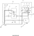
- FIGS 2A to 2D show a decoder-receiver STB 300 according to different embodiments of the present disclosure.
- the STB is adapted to receive RF signals (like audiovisual programs or DOCSIS data) over a cable network via at least one cable 350.
- the STB is also adapted to transmit DC current by the way of the same cable 350.
- the STB can supply Direct Current via the cable to a LNB of a receiver of a satellite antenna.
- the STB comprises at least one embedded galvanic isolator 324, 326 with the capability to deliver on at least one RF connector 352 of the STB a remote voltage (and control signals if necessary) to an external device (like single LNB, digital LNB, active antenna with amplifier for instance).
- an external device like single LNB, digital LNB, active antenna with amplifier for instance.
- Such an embodiment can permit to the same STB to be adapted to be used in a collective installation (cable, SMATV or equivalent) or to an individual installation (like dish with LNB, external active antenna with amplifier).
- the STB comprises two separate grounding areas 310, 330 linked together by one or several galvanic isolation modules 324, 326 and by at least one isolated supply module 322 (for instance an isolated supply having a DC/DC fly back topology).
- the isolated supply can vary upon embodiments and notably according to the needed power to be output by the electric device. Depending upon embodiments, the isolated supply can be adapted to provide a large range of power, for instance in the order of 0 to several tens of watts (for instance 350 mA with a voltage of 18V, 450 mA with a voltage of 18V, 1 Watt, 10 Wat, 15 Watt, 18 Watt, 25 Watt, 36 Watts).
- the first ground area also called herein "front-end area”, “front-end component”, “front-end unit” or “front-end module”
- the first ground area comprises at least one front-end connector 352 suitable for the connection of the cable 350 and at least one control and/or supply module, like a controller 336, which is adapted to supply DC power, and in some embodiments control signals, via the front-end connector and the cable 350, to a LNB module of a reception module of an antenna (like a satellite antenna).
- a second grounding area 310 also called herein "back-end area”, “back-end component”, “back-end unit” or “back-end module”, embed a Control and Processing Unit (CPU) 312 and is connected to a DC power line 340. All details of the back-end module are not illustrated in figures 2A to 2D , as their description is not considered as useful to the understanding of the present disclosure for the one skilled in the art.
- the back-end module can comprise, amongst others, a CPU module and a volatile memory, a non-volatile memory, a de-multiplexer, a decoder, a display memory and interface circuits for outputting to a reproduction device (like a TV set or instance).
- the CPU can notably manage the control module 336 of the front-end module by means of controls and/or communication signals (like signals of type GPIO, I2C bus, Reset, controls signals like signals compatible with Digital Satellite Equipment Control (DiSEqC) standard) send through the galvanic isolated module (for instance through an opto-coupler component of the galvanic isolated module).
- the STB can also comprise a User Interface (like screen, buttons, %)
- the presence of the galvanic isolation modules 324, 326 between the first and second ground area can help to prevent DC signal continuity and connection between the ground GND6 337 of the front-end area to the ground GND7 317 of the back-end area as thus to prevent current loops, as already explained.
- the isolated supply module 322 receives DC power via the second grounding area 330 from an input voltage line (for instance a voltage line belonging to an interval of [2 V; 30V] like 3V, 5V, 12V, 18V, 19V, 25V]. 340 and supply DC voltage to at least some module of the front-end area 310.
- an input voltage line for instance a voltage line belonging to an interval of [2 V; 30V] like 3V, 5V, 12V, 18V, 19V, 25V.
- the RF receiving path of the STB is secured by the presence of the galvanic isolation module(s) and the galvanic isolation modules are not used in the Direct Current supplying path between the DC power line 340 and the cable 350 and thus do not prevent the supply of DC power by the STB.
- At least some embodiments of the present disclosure can thus permit to provide an STB adapted to operate in at least two different modes (RF reception with or without DC (and/or control) supplying), depending for instance on the type and/or the role of the cable connected to the STB.
- the galvanic isolator module can vary upon embodiments.
- at least one of the galvanic isolator module(s) can comprise a transformer with windings, the signals input by the front-end module to a first winding of the transformer being transmitting by magnetic coupling to a second winding of the transformer and then output to the back-end module.
- At least one of the galvanic isolator module(s) can comprise capacitors enabling the transmission of high-frequency signals and having an infinite DC impedance.
- a first capacitor can be used to link the signals coding the audiovisual programs contained in the RF signal received over the cable 350, a second capacitor can be used for the small signal earth ground.
- at least one of the galvanic isolator module(s) can comprise an optical device like an opto-coupler.
- the galvanic isolator modules can be identical or different.
- integrating a galvanic isolation device into the STB makes it possible to reduce the overall cost of the installation protected against the occurrence of current loops and makes it possible to avoid the risk of damage to equipment.
- the front-end area also comprises a RF reception and filtering module 332 (or RF receiver), which is adapted to receive RF signals, via the front-end connector 352.
- the RF reception module 332 can output RF signals to a galvanic isolator module 326.
- At least some embodiment where the isolating between the front-end area and the back-end area is performed at the RF stage can be adapted to situation where major integration constraint and/or major cost constraint are encountered.
- the front-end area 310 also comprises a Tuning and demodulating Module 334 (like a tuner and/or a demodulator) which receive RF signals output by the RF reception module 332.
- the Tuning and demodulating module 334 transforms the RF signal received in a Transport Stream (TS) signal that is output to the galvanic isolator module 326.
- TS Transport Stream
- the RF reception module and the tuning and/or demodulating module are separate units or entities.
- the RF reception module can be integrated in the tuning and /or demodulating module.
- the STB can be configured in one or the other mode (RF reception with or without DC (and/or control) supplying).
- the configured mode can notably depend of the type of network to which the STB is linked via the cable 350. Indeed, when the STB is linked via the cable to a collective installation (cable, SMATV or equivalent) (for instance when the STB is installed in a building), DC supplying may not be necessary. At the opposite, when the STB is installed in a house, or other kind of individual installation (like dish with LNB, external active antenna with amplifierCertainly DC supplying may be required.
- the STB can be configured in one or the other mode, via a User interface of the STB, notably by interacting with a user via a display with a software interface or via a remote-control device (like an infra-red remote-control device).
- a remote-control device like an infra-red remote-control device.
- the command of the control module can be performed from the CPU of the back-end module (after receiving a request from the User Interface for instance).
- the commutation command can be included in General Purpose Input/ Output (GPIO) signals received by the control module through an opto-coupler of the galvanic isolating module.
- the opto-coupler buffers the mode (or in other words stores the switch state) from the back-end area to the front-end area.
- the mode of the STB can be stored of a persistent memory of the STB.
- the embodiment illustrated by figure 2C is similar to the embodiment illustrated in figure 2A except that a switch 360 is added to the STB 300.
- the switch 360 can be accessible from the outside of the STB and can be adapted to commute the STB between the different modes (RF reception with or without DC (and/or control) supplying). For instance, it can be manually actuated.
- Such an embodiment can be used in a STB with no user interface or a user interface with limited functionalities. It can be adapted for instance to installation where the STB is configured by a technician or even by the end user itself, as the switch only controls the GPIO and does not connect both ground (thus the actuation of the switch 360 do not lead to safety risks).
- the switch 360 can be an elementary switch, like a micro-switch, adapted to control a logical state of a command signal. It does not need to be a power switch.
- the actuation of the switch controls the commutation of an electrical command signal, in voltage, which can take at least two logical values (like 0 or 1).
- the commutation of the command signal can be further detected by the CPU 312 of the back-end area 310 for instance, and used for controlling the transmission of control signal (like i2C signal for instance) to the supply and/or control module 336 of the front-end area 330 and/or for managing the isolated supply 322, thus permitting an interaction of the back-end area 310 with the front-end area 330, the supplying of direct current and/or the transmission of control signal to the cable.
- the command signal can be conveyed from the switch 360 to the front-end area 330 thanks to a galvanic isolator and analyzed in a microprocessor of the front-end area in order to pilot the isolated supply 322 according to the command signal.
- FIG. 2D The embodiment illustrated by figure 2D is similar to the embodiment illustrated in figure 2B except that the mode of the STB is controlled by an external switch 360 as already explained in link with figure 2C .
- the front-end connector can be accessible from a rear panel of the STB, made for instance at least partially of non-conductive (isolating) material such as plastic,
- the metallic parts of the other connectors can be hidden inside the rear panel, in order to prevent hazardous voltage risk due to the galvanic isolator configuration.
- the present disclosure is not limited to the embodiments described above but also applies to any device enabling the reception of electrical signals received by cable and comprising galvanic isolation means configured to prevent the occurrence of induced current loops when two devices respectively connected to earth and not connected to earth are interconnected by a wired link.
- the electronic device can comprise one, two or several front-end connector(s) (each providing RF signal to a galvanically isolated communication path), one, two or several isolated supply module(s), and/or one, two or several front-end control module(s).
- each control module can provide DC current through one, two or several front-end connectors.
- a front-end control module can comprise several LNB module, or dual LNB modules.
- the present disclosure also applies, for example, to a desktop computer, a laptop computer, a tablet, a television set, a hi-fi system or a gateway for accessing a broadband communication network.
- the electrical signal can be an audiovisual signal, or a telecommunication signal, representing high data rate, like data received from a network compatible with the Data Over Cable Service Interface Specification (DOCSIS) standard. It can comprise multiplexed signals comprising different types of data, like data with different formats (for instance audiovisual data, and/or telecommunication data (like voice, data compatible with an internet protocol (IP), control data)).
- DOCSIS Data Over Cable Service Interface Specification
- Figure 3 illustrates a method for processing an electrical signal according to at least one embodiment of the present disclosure.
- the method can be implemented for instance in an electronic device as the electronic device 300 illustrated by figure 2A, 2B , 2C or 2D .
- the method comprises:
- the method can comprise:
Landscapes
- Engineering & Computer Science (AREA)
- Multimedia (AREA)
- Signal Processing (AREA)
- Power Engineering (AREA)
- Two-Way Televisions, Distribution Of Moving Picture Or The Like (AREA)
Applications Claiming Priority (2)
| Application Number | Priority Date | Filing Date | Title |
|---|---|---|---|
| EP16305900 | 2016-07-12 | ||
| EP16183670.5A EP3282690A1 (de) | 2016-08-11 | 2016-08-11 | Galvanisch isolierte vorrichtung und entsprechendes verfahren und system |
Publications (2)
| Publication Number | Publication Date |
|---|---|
| EP3270584A1 true EP3270584A1 (de) | 2018-01-17 |
| EP3270584B1 EP3270584B1 (de) | 2020-09-02 |
Family
ID=59215666
Family Applications (1)
| Application Number | Title | Priority Date | Filing Date |
|---|---|---|---|
| EP17179350.8A Active EP3270584B1 (de) | 2016-07-12 | 2017-07-03 | Galvanisch isolierte vorrichtung und entsprechendes verfahren und system |
Country Status (3)
| Country | Link |
|---|---|
| US (1) | US20180019681A1 (de) |
| EP (1) | EP3270584B1 (de) |
| CN (1) | CN107613334B (de) |
Cited By (2)
| Publication number | Priority date | Publication date | Assignee | Title |
|---|---|---|---|---|
| KR20200030407A (ko) * | 2018-09-12 | 2020-03-20 | 삼성전자주식회사 | 디스플레이 시스템, 디스플레이 장치 및 그 제어 방법 |
| US11501693B2 (en) | 2019-07-17 | 2022-11-15 | Samsung Electronics Co., Ltd. | Electronic apparatus transmitting power to a display apparatus, control method thereof and display apparatus receiving power |
Citations (3)
| Publication number | Priority date | Publication date | Assignee | Title |
|---|---|---|---|---|
| US5436675A (en) * | 1991-08-30 | 1995-07-25 | Sony Corporation | Television receiver with UHF/VHF and broadcast satellite tuners, power switch state display antenna reception level display, and external decoder output and input terminals |
| WO1997026762A1 (en) * | 1996-01-16 | 1997-07-24 | Hughes Aircraft Company | Satellite receiver computer adapter card |
| US20090167465A1 (en) * | 2007-12-28 | 2009-07-02 | Henry Gregg Martch | Apparatus and systems for electrically isolating and transmitting rf signals between two devices |
Family Cites Families (21)
| Publication number | Priority date | Publication date | Assignee | Title |
|---|---|---|---|---|
| US6125044A (en) * | 1999-03-23 | 2000-09-26 | Hewlett-Packard Company | Suppressing EMI with PCB mounted ferrite attenuator |
| SE0004936D0 (sv) * | 2000-12-29 | 2000-12-29 | Nokia Corp | Common interface module and method related thereto |
| US7793137B2 (en) * | 2004-10-07 | 2010-09-07 | Cisco Technology, Inc. | Redundant power and data in a wired data telecommunincations network |
| US7675922B2 (en) * | 2004-10-29 | 2010-03-09 | Microsoft Corporation | System and method for providing a universal communications port with computer-telephony interface |
| US20060217847A1 (en) * | 2005-03-28 | 2006-09-28 | Adc Telecommunications, Inc. | Power sourcing unit for power over ethernet system |
| JP4961999B2 (ja) * | 2006-12-25 | 2012-06-27 | 株式会社ニコン | 電子機器 |
| US9185834B2 (en) * | 2007-04-24 | 2015-11-10 | Akros Silicon, Inc. | Isolated ethernet physical layer (PHY) |
| FR2917932A1 (fr) * | 2007-06-19 | 2008-12-26 | Thomson Licensing Sas | Procede de detection de canaux de transmission satellitaires et dispositif de reception utilisant le procede. |
| US8363388B2 (en) * | 2008-10-17 | 2013-01-29 | Emerson Network Power—Embedded Computing, Inc. | System and method for supplying power to electronics enclosures utilizing distributed DC power architectures |
| US20100280676A1 (en) * | 2009-04-30 | 2010-11-04 | Pabon Gus Charles | Multi-functional Bi-directional Communication and Bias Power Architecture for Power Supply Control |
| US9565471B2 (en) * | 2009-07-24 | 2017-02-07 | Broadcom Corporation | Method and system for PVR on internet enabled televisions (TVs) |
| US20110062333A1 (en) * | 2009-09-14 | 2011-03-17 | David Ben-Bassat | Electromagnetic based thermal sensing and imaging incorporating multi-pixel imaging arrays |
| US8674679B2 (en) * | 2009-10-08 | 2014-03-18 | Qualcomm Incorporated | Power saving during a connection detection |
| US20120155514A1 (en) * | 2010-12-17 | 2012-06-21 | Echostar Technologies L.L.C | Device for employing a portable communication device for antenna orientation optimization |
| JP5505742B2 (ja) * | 2012-01-18 | 2014-05-28 | 横河電機株式会社 | 計測用アナログフロントエンド回路 |
| US9584858B2 (en) * | 2012-03-19 | 2017-02-28 | Rentrak Corporation | Empirical ad pod detection |
| US9348382B2 (en) * | 2013-02-22 | 2016-05-24 | Maxim Integrated Products, Inc. | Method and apparatus for providing power to an electronic device |
| JP6247761B2 (ja) * | 2013-08-06 | 2017-12-13 | ベドロック・オートメーション・プラットフォームズ・インコーポレーテッド | 産業用制御システムのモジュール種別を強化する方法 |
| US10855551B2 (en) * | 2014-12-31 | 2020-12-01 | Dell Products L.P. | Multi-port selection and configuration |
| EP3091632B1 (de) * | 2015-05-07 | 2018-01-17 | Richtek Technology Corporation | Ladungssteuerungsschaltung einer mobilen vorrichtung |
| EP3317802B1 (de) * | 2015-09-15 | 2019-05-29 | Gatekeeper Ltd. | System und verfahren zur sicheren verbindung mit einem peripherievorrichtung |
-
2017
- 2017-07-03 EP EP17179350.8A patent/EP3270584B1/de active Active
- 2017-07-11 CN CN201710564551.4A patent/CN107613334B/zh active Active
- 2017-07-12 US US15/647,316 patent/US20180019681A1/en not_active Abandoned
Patent Citations (3)
| Publication number | Priority date | Publication date | Assignee | Title |
|---|---|---|---|---|
| US5436675A (en) * | 1991-08-30 | 1995-07-25 | Sony Corporation | Television receiver with UHF/VHF and broadcast satellite tuners, power switch state display antenna reception level display, and external decoder output and input terminals |
| WO1997026762A1 (en) * | 1996-01-16 | 1997-07-24 | Hughes Aircraft Company | Satellite receiver computer adapter card |
| US20090167465A1 (en) * | 2007-12-28 | 2009-07-02 | Henry Gregg Martch | Apparatus and systems for electrically isolating and transmitting rf signals between two devices |
Non-Patent Citations (1)
| Title |
|---|
| VISION PRODUCTS EUROPE LTD: "V5-025 Galvanic Isolator for IRS and MATV System; Safety Galvanic Isolator for interconnecting buildings/dwellings", INTERNET CITATION, September 2009 (2009-09-01), pages 1, XP002729706, Retrieved from the Internet <URL:http://www.vision-products.co.uk/app/uploads/product_files/479/v5-025_galvanic_isolator.pdf> [retrieved on 20140915] * |
Cited By (4)
| Publication number | Priority date | Publication date | Assignee | Title |
|---|---|---|---|---|
| KR20200030407A (ko) * | 2018-09-12 | 2020-03-20 | 삼성전자주식회사 | 디스플레이 시스템, 디스플레이 장치 및 그 제어 방법 |
| US11226783B2 (en) | 2018-09-12 | 2022-01-18 | Samsung Electronics Co., Ltd. | Display system, display apparatus, and control method thereof |
| EP3624095B1 (de) * | 2018-09-12 | 2026-01-28 | Samsung Electronics Co., Ltd. | Anzeigesystem, anzeigevorrichtung und steuerungsverfahren dafür |
| US11501693B2 (en) | 2019-07-17 | 2022-11-15 | Samsung Electronics Co., Ltd. | Electronic apparatus transmitting power to a display apparatus, control method thereof and display apparatus receiving power |
Also Published As
| Publication number | Publication date |
|---|---|
| CN107613334B (zh) | 2021-03-30 |
| CN107613334A (zh) | 2018-01-19 |
| US20180019681A1 (en) | 2018-01-18 |
| BR102017014949A2 (pt) | 2018-03-20 |
| EP3270584B1 (de) | 2020-09-02 |
Similar Documents
| Publication | Publication Date | Title |
|---|---|---|
| US7933106B2 (en) | Surge protection device for coaxial cable with diagnostic capabilities | |
| US7856207B2 (en) | Apparatus and systems for electrically isolating and transmitting RF signals between two devices | |
| TW200402991A (en) | Method and apparatus for implementing a scaled upgrading of an upgradeable set-top box | |
| CN101715616A (zh) | 用于单线多开关收发器的两级冲击保护器 | |
| US20090244391A1 (en) | Electronic Apparatus and Control Method of Electronic Apparatus | |
| RU2464724C1 (ru) | Модульный приемник цифровой мультимедийной информации | |
| EP3270584B1 (de) | Galvanisch isolierte vorrichtung und entsprechendes verfahren und system | |
| US8930610B2 (en) | System and method for transmitting control signals over HDMI | |
| EP2003889A2 (de) | Anzeigevorrichtung und Verfahren zum Bestimmen des Status einer Audioschnittstelle | |
| EP3840238B1 (de) | Verfahren und vorrichtung zur plc-steuerung | |
| EP3282690A1 (de) | Galvanisch isolierte vorrichtung und entsprechendes verfahren und system | |
| WO2019070283A1 (en) | NETWORKING MODULES FOR DISPLAY SYSTEMS | |
| CN105264882B (zh) | 显示装置的功能扩展件及其控制方法 | |
| GB2254512A (en) | Selectively interconnecting units in audio-visual systems | |
| US20070199016A1 (en) | Method of controlling emergency alert system in digital cable broadcasting, signal thereof and cable broadcast receiver | |
| CN104363432A (zh) | 一种单电缆复合开关系统 | |
| CN114642001B (zh) | 控制电路、接收装置及控制方法 | |
| BR102017014949B1 (pt) | Dispositivo de isolamento galvânico e método de processamento de um sinal elétrico | |
| JP4982298B2 (ja) | スプリッタ、plcアダプタ内蔵型スプリッタおよび屋内ネットワークシステム | |
| US8320563B2 (en) | Service card adapter | |
| EP2924983A1 (de) | Potenzialtrennvorrichtung, Stecker und zugehöriger Artikel von Geräten | |
| KR20110036396A (ko) | 디스플레이장치 및 텔레비전과, 디스플레이장치의 전원출력 제어방법 | |
| JP5317693B2 (ja) | 高精細度及び標準精細度のデジタルテレビジョンデコーダ | |
| KR100837066B1 (ko) | 지역별 tv 방송 시스템을 통합하여 관리하는 tv방송시스템 및 셋톱박스 | |
| JP6936598B2 (ja) | 受信装置 |
Legal Events
| Date | Code | Title | Description |
|---|---|---|---|
| PUAI | Public reference made under article 153(3) epc to a published international application that has entered the european phase |
Free format text: ORIGINAL CODE: 0009012 |
|
| STAA | Information on the status of an ep patent application or granted ep patent |
Free format text: STATUS: THE APPLICATION HAS BEEN PUBLISHED |
|
| AK | Designated contracting states |
Kind code of ref document: A1 Designated state(s): AL AT BE BG CH CY CZ DE DK EE ES FI FR GB GR HR HU IE IS IT LI LT LU LV MC MK MT NL NO PL PT RO RS SE SI SK SM TR |
|
| AX | Request for extension of the european patent |
Extension state: BA ME |
|
| STAA | Information on the status of an ep patent application or granted ep patent |
Free format text: STATUS: REQUEST FOR EXAMINATION WAS MADE |
|
| 17P | Request for examination filed |
Effective date: 20180712 |
|
| RBV | Designated contracting states (corrected) |
Designated state(s): AL AT BE BG CH CY CZ DE DK EE ES FI FR GB GR HR HU IE IS IT LI LT LU LV MC MK MT NL NO PL PT RO RS SE SI SK SM TR |
|
| STAA | Information on the status of an ep patent application or granted ep patent |
Free format text: STATUS: EXAMINATION IS IN PROGRESS |
|
| 17Q | First examination report despatched |
Effective date: 20181008 |
|
| RAP1 | Party data changed (applicant data changed or rights of an application transferred) |
Owner name: INTERDIGITAL CE PATENT HOLDINGS |
|
| GRAP | Despatch of communication of intention to grant a patent |
Free format text: ORIGINAL CODE: EPIDOSNIGR1 |
|
| STAA | Information on the status of an ep patent application or granted ep patent |
Free format text: STATUS: GRANT OF PATENT IS INTENDED |
|
| INTG | Intention to grant announced |
Effective date: 20200205 |
|
| GRAJ | Information related to disapproval of communication of intention to grant by the applicant or resumption of examination proceedings by the epo deleted |
Free format text: ORIGINAL CODE: EPIDOSDIGR1 |
|
| STAA | Information on the status of an ep patent application or granted ep patent |
Free format text: STATUS: EXAMINATION IS IN PROGRESS |
|
| GRAR | Information related to intention to grant a patent recorded |
Free format text: ORIGINAL CODE: EPIDOSNIGR71 |
|
| GRAS | Grant fee paid |
Free format text: ORIGINAL CODE: EPIDOSNIGR3 |
|
| STAA | Information on the status of an ep patent application or granted ep patent |
Free format text: STATUS: GRANT OF PATENT IS INTENDED |
|
| INTC | Intention to grant announced (deleted) | ||
| INTG | Intention to grant announced |
Effective date: 20200608 |
|
| GRAA | (expected) grant |
Free format text: ORIGINAL CODE: 0009210 |
|
| STAA | Information on the status of an ep patent application or granted ep patent |
Free format text: STATUS: THE PATENT HAS BEEN GRANTED |
|
| AK | Designated contracting states |
Kind code of ref document: B1 Designated state(s): AL AT BE BG CH CY CZ DE DK EE ES FI FR GB GR HR HU IE IS IT LI LT LU LV MC MK MT NL NO PL PT RO RS SE SI SK SM TR |
|
| REG | Reference to a national code |
Ref country code: GB Ref legal event code: FG4D |
|
| REG | Reference to a national code |
Ref country code: AT Ref legal event code: REF Ref document number: 1310170 Country of ref document: AT Kind code of ref document: T Effective date: 20200915 Ref country code: CH Ref legal event code: EP |
|
| REG | Reference to a national code |
Ref country code: DE Ref legal event code: R096 Ref document number: 602017022639 Country of ref document: DE |
|
| REG | Reference to a national code |
Ref country code: IE Ref legal event code: FG4D |
|
| REG | Reference to a national code |
Ref country code: GB Ref legal event code: 732E Free format text: REGISTERED BETWEEN 20201217 AND 20201223 |
|
| REG | Reference to a national code |
Ref country code: LT Ref legal event code: MG4D |
|
| PG25 | Lapsed in a contracting state [announced via postgrant information from national office to epo] |
Ref country code: FI Free format text: LAPSE BECAUSE OF FAILURE TO SUBMIT A TRANSLATION OF THE DESCRIPTION OR TO PAY THE FEE WITHIN THE PRESCRIBED TIME-LIMIT Effective date: 20200902 Ref country code: GR Free format text: LAPSE BECAUSE OF FAILURE TO SUBMIT A TRANSLATION OF THE DESCRIPTION OR TO PAY THE FEE WITHIN THE PRESCRIBED TIME-LIMIT Effective date: 20201203 Ref country code: NO Free format text: LAPSE BECAUSE OF FAILURE TO SUBMIT A TRANSLATION OF THE DESCRIPTION OR TO PAY THE FEE WITHIN THE PRESCRIBED TIME-LIMIT Effective date: 20201202 Ref country code: HR Free format text: LAPSE BECAUSE OF FAILURE TO SUBMIT A TRANSLATION OF THE DESCRIPTION OR TO PAY THE FEE WITHIN THE PRESCRIBED TIME-LIMIT Effective date: 20200902 Ref country code: SE Free format text: LAPSE BECAUSE OF FAILURE TO SUBMIT A TRANSLATION OF THE DESCRIPTION OR TO PAY THE FEE WITHIN THE PRESCRIBED TIME-LIMIT Effective date: 20200902 Ref country code: BG Free format text: LAPSE BECAUSE OF FAILURE TO SUBMIT A TRANSLATION OF THE DESCRIPTION OR TO PAY THE FEE WITHIN THE PRESCRIBED TIME-LIMIT Effective date: 20201202 Ref country code: LT Free format text: LAPSE BECAUSE OF FAILURE TO SUBMIT A TRANSLATION OF THE DESCRIPTION OR TO PAY THE FEE WITHIN THE PRESCRIBED TIME-LIMIT Effective date: 20200902 |
|
| REG | Reference to a national code |
Ref country code: NL Ref legal event code: MP Effective date: 20200902 |
|
| REG | Reference to a national code |
Ref country code: AT Ref legal event code: MK05 Ref document number: 1310170 Country of ref document: AT Kind code of ref document: T Effective date: 20200902 |
|
| RAP2 | Party data changed (patent owner data changed or rights of a patent transferred) |
Owner name: INTERDIGITAL MADISON PATENT HOLDINGS, SAS |
|
| PG25 | Lapsed in a contracting state [announced via postgrant information from national office to epo] |
Ref country code: PL Free format text: LAPSE BECAUSE OF FAILURE TO SUBMIT A TRANSLATION OF THE DESCRIPTION OR TO PAY THE FEE WITHIN THE PRESCRIBED TIME-LIMIT Effective date: 20200902 Ref country code: LV Free format text: LAPSE BECAUSE OF FAILURE TO SUBMIT A TRANSLATION OF THE DESCRIPTION OR TO PAY THE FEE WITHIN THE PRESCRIBED TIME-LIMIT Effective date: 20200902 Ref country code: RS Free format text: LAPSE BECAUSE OF FAILURE TO SUBMIT A TRANSLATION OF THE DESCRIPTION OR TO PAY THE FEE WITHIN THE PRESCRIBED TIME-LIMIT Effective date: 20200902 |
|
| PG25 | Lapsed in a contracting state [announced via postgrant information from national office to epo] |
Ref country code: EE Free format text: LAPSE BECAUSE OF FAILURE TO SUBMIT A TRANSLATION OF THE DESCRIPTION OR TO PAY THE FEE WITHIN THE PRESCRIBED TIME-LIMIT Effective date: 20200902 Ref country code: SM Free format text: LAPSE BECAUSE OF FAILURE TO SUBMIT A TRANSLATION OF THE DESCRIPTION OR TO PAY THE FEE WITHIN THE PRESCRIBED TIME-LIMIT Effective date: 20200902 Ref country code: CZ Free format text: LAPSE BECAUSE OF FAILURE TO SUBMIT A TRANSLATION OF THE DESCRIPTION OR TO PAY THE FEE WITHIN THE PRESCRIBED TIME-LIMIT Effective date: 20200902 Ref country code: PT Free format text: LAPSE BECAUSE OF FAILURE TO SUBMIT A TRANSLATION OF THE DESCRIPTION OR TO PAY THE FEE WITHIN THE PRESCRIBED TIME-LIMIT Effective date: 20210104 Ref country code: RO Free format text: LAPSE BECAUSE OF FAILURE TO SUBMIT A TRANSLATION OF THE DESCRIPTION OR TO PAY THE FEE WITHIN THE PRESCRIBED TIME-LIMIT Effective date: 20200902 |
|
| PG25 | Lapsed in a contracting state [announced via postgrant information from national office to epo] |
Ref country code: ES Free format text: LAPSE BECAUSE OF FAILURE TO SUBMIT A TRANSLATION OF THE DESCRIPTION OR TO PAY THE FEE WITHIN THE PRESCRIBED TIME-LIMIT Effective date: 20200902 Ref country code: AL Free format text: LAPSE BECAUSE OF FAILURE TO SUBMIT A TRANSLATION OF THE DESCRIPTION OR TO PAY THE FEE WITHIN THE PRESCRIBED TIME-LIMIT Effective date: 20200902 Ref country code: AT Free format text: LAPSE BECAUSE OF FAILURE TO SUBMIT A TRANSLATION OF THE DESCRIPTION OR TO PAY THE FEE WITHIN THE PRESCRIBED TIME-LIMIT Effective date: 20200902 Ref country code: IS Free format text: LAPSE BECAUSE OF FAILURE TO SUBMIT A TRANSLATION OF THE DESCRIPTION OR TO PAY THE FEE WITHIN THE PRESCRIBED TIME-LIMIT Effective date: 20210102 |
|
| REG | Reference to a national code |
Ref country code: DE Ref legal event code: R097 Ref document number: 602017022639 Country of ref document: DE |
|
| PG25 | Lapsed in a contracting state [announced via postgrant information from national office to epo] |
Ref country code: SK Free format text: LAPSE BECAUSE OF FAILURE TO SUBMIT A TRANSLATION OF THE DESCRIPTION OR TO PAY THE FEE WITHIN THE PRESCRIBED TIME-LIMIT Effective date: 20200902 |
|
| PLBE | No opposition filed within time limit |
Free format text: ORIGINAL CODE: 0009261 |
|
| STAA | Information on the status of an ep patent application or granted ep patent |
Free format text: STATUS: NO OPPOSITION FILED WITHIN TIME LIMIT |
|
| 26N | No opposition filed |
Effective date: 20210603 |
|
| PG25 | Lapsed in a contracting state [announced via postgrant information from national office to epo] |
Ref country code: DK Free format text: LAPSE BECAUSE OF FAILURE TO SUBMIT A TRANSLATION OF THE DESCRIPTION OR TO PAY THE FEE WITHIN THE PRESCRIBED TIME-LIMIT Effective date: 20200902 Ref country code: SI Free format text: LAPSE BECAUSE OF FAILURE TO SUBMIT A TRANSLATION OF THE DESCRIPTION OR TO PAY THE FEE WITHIN THE PRESCRIBED TIME-LIMIT Effective date: 20200902 |
|
| PG25 | Lapsed in a contracting state [announced via postgrant information from national office to epo] |
Ref country code: IT Free format text: LAPSE BECAUSE OF FAILURE TO SUBMIT A TRANSLATION OF THE DESCRIPTION OR TO PAY THE FEE WITHIN THE PRESCRIBED TIME-LIMIT Effective date: 20200902 |
|
| REG | Reference to a national code |
Ref country code: CH Ref legal event code: PL |
|
| PG25 | Lapsed in a contracting state [announced via postgrant information from national office to epo] |
Ref country code: MC Free format text: LAPSE BECAUSE OF FAILURE TO SUBMIT A TRANSLATION OF THE DESCRIPTION OR TO PAY THE FEE WITHIN THE PRESCRIBED TIME-LIMIT Effective date: 20200902 |
|
| REG | Reference to a national code |
Ref country code: BE Ref legal event code: MM Effective date: 20210731 |
|
| REG | Reference to a national code |
Ref country code: DE Ref legal event code: R081 Ref document number: 602017022639 Country of ref document: DE Owner name: INTERDIGITAL MADISON PATENT HOLDINGS, SAS, FR Free format text: FORMER OWNER: INTERDIGITAL CE PATENT HOLDINGS, PARIS, FR |
|
| PG25 | Lapsed in a contracting state [announced via postgrant information from national office to epo] |
Ref country code: LI Free format text: LAPSE BECAUSE OF NON-PAYMENT OF DUE FEES Effective date: 20210731 Ref country code: CH Free format text: LAPSE BECAUSE OF NON-PAYMENT OF DUE FEES Effective date: 20210731 |
|
| PG25 | Lapsed in a contracting state [announced via postgrant information from national office to epo] |
Ref country code: LU Free format text: LAPSE BECAUSE OF NON-PAYMENT OF DUE FEES Effective date: 20210703 |
|
| PG25 | Lapsed in a contracting state [announced via postgrant information from national office to epo] |
Ref country code: IE Free format text: LAPSE BECAUSE OF NON-PAYMENT OF DUE FEES Effective date: 20210703 Ref country code: BE Free format text: LAPSE BECAUSE OF NON-PAYMENT OF DUE FEES Effective date: 20210731 |
|
| PG25 | Lapsed in a contracting state [announced via postgrant information from national office to epo] |
Ref country code: HU Free format text: LAPSE BECAUSE OF FAILURE TO SUBMIT A TRANSLATION OF THE DESCRIPTION OR TO PAY THE FEE WITHIN THE PRESCRIBED TIME-LIMIT; INVALID AB INITIO Effective date: 20170703 |
|
| P01 | Opt-out of the competence of the unified patent court (upc) registered |
Effective date: 20230514 |
|
| PG25 | Lapsed in a contracting state [announced via postgrant information from national office to epo] |
Ref country code: NL Free format text: LAPSE BECAUSE OF NON-PAYMENT OF DUE FEES Effective date: 20200923 Ref country code: CY Free format text: LAPSE BECAUSE OF FAILURE TO SUBMIT A TRANSLATION OF THE DESCRIPTION OR TO PAY THE FEE WITHIN THE PRESCRIBED TIME-LIMIT Effective date: 20200902 |
|
| PG25 | Lapsed in a contracting state [announced via postgrant information from national office to epo] |
Ref country code: MK Free format text: LAPSE BECAUSE OF FAILURE TO SUBMIT A TRANSLATION OF THE DESCRIPTION OR TO PAY THE FEE WITHIN THE PRESCRIBED TIME-LIMIT Effective date: 20200902 |
|
| PG25 | Lapsed in a contracting state [announced via postgrant information from national office to epo] |
Ref country code: MT Free format text: LAPSE BECAUSE OF FAILURE TO SUBMIT A TRANSLATION OF THE DESCRIPTION OR TO PAY THE FEE WITHIN THE PRESCRIBED TIME-LIMIT Effective date: 20200902 |
|
| PGFP | Annual fee paid to national office [announced via postgrant information from national office to epo] |
Ref country code: DE Payment date: 20250728 Year of fee payment: 9 |
|
| PGFP | Annual fee paid to national office [announced via postgrant information from national office to epo] |
Ref country code: GB Payment date: 20250722 Year of fee payment: 9 |
|
| PGFP | Annual fee paid to national office [announced via postgrant information from national office to epo] |
Ref country code: FR Payment date: 20250725 Year of fee payment: 9 |
|
| PG25 | Lapsed in a contracting state [announced via postgrant information from national office to epo] |
Ref country code: TR Free format text: LAPSE BECAUSE OF FAILURE TO SUBMIT A TRANSLATION OF THE DESCRIPTION OR TO PAY THE FEE WITHIN THE PRESCRIBED TIME-LIMIT Effective date: 20200902 |