EP3270501A1 - Device for transferring electrical energy via hvdc - Google Patents
Device for transferring electrical energy via hvdc Download PDFInfo
- Publication number
- EP3270501A1 EP3270501A1 EP17001325.4A EP17001325A EP3270501A1 EP 3270501 A1 EP3270501 A1 EP 3270501A1 EP 17001325 A EP17001325 A EP 17001325A EP 3270501 A1 EP3270501 A1 EP 3270501A1
- Authority
- EP
- European Patent Office
- Prior art keywords
- voltage
- power converter
- phase
- transmission
- power
- Prior art date
- Legal status (The legal status is an assumption and is not a legal conclusion. Google has not performed a legal analysis and makes no representation as to the accuracy of the status listed.)
- Granted
Links
- 230000005540 biological transmission Effects 0.000 claims abstract description 109
- 238000004146 energy storage Methods 0.000 claims abstract description 34
- 239000004065 semiconductor Substances 0.000 claims abstract description 19
- 239000003990 capacitor Substances 0.000 claims description 28
- 230000001105 regulatory effect Effects 0.000 claims description 4
- 238000004804 winding Methods 0.000 claims description 3
- 238000009826 distribution Methods 0.000 abstract description 5
- 230000008878 coupling Effects 0.000 description 14
- 238000010168 coupling process Methods 0.000 description 14
- 238000005859 coupling reaction Methods 0.000 description 14
- 238000011161 development Methods 0.000 description 8
- 238000013461 design Methods 0.000 description 6
- 238000009499 grossing Methods 0.000 description 6
- 230000033228 biological regulation Effects 0.000 description 5
- 230000001360 synchronised effect Effects 0.000 description 5
- 230000008901 benefit Effects 0.000 description 4
- 239000004020 conductor Substances 0.000 description 4
- 230000001276 controlling effect Effects 0.000 description 4
- 230000003068 static effect Effects 0.000 description 4
- 230000002950 deficient Effects 0.000 description 3
- 238000005259 measurement Methods 0.000 description 3
- 230000000712 assembly Effects 0.000 description 2
- 238000000429 assembly Methods 0.000 description 2
- 238000013016 damping Methods 0.000 description 2
- 230000000694 effects Effects 0.000 description 2
- 238000001914 filtration Methods 0.000 description 2
- 238000000034 method Methods 0.000 description 2
- 230000010355 oscillation Effects 0.000 description 2
- 230000009467 reduction Effects 0.000 description 2
- 230000006641 stabilisation Effects 0.000 description 2
- 238000011105 stabilization Methods 0.000 description 2
- 238000005406 washing Methods 0.000 description 2
- 230000009471 action Effects 0.000 description 1
- 230000004913 activation Effects 0.000 description 1
- 238000001994 activation Methods 0.000 description 1
- 238000004891 communication Methods 0.000 description 1
- 238000005516 engineering process Methods 0.000 description 1
- 238000012423 maintenance Methods 0.000 description 1
- 230000005405 multipole Effects 0.000 description 1
- 230000000087 stabilizing effect Effects 0.000 description 1
- 238000012549 training Methods 0.000 description 1
- 238000012546 transfer Methods 0.000 description 1
- XLYOFNOQVPJJNP-UHFFFAOYSA-N water Substances O XLYOFNOQVPJJNP-UHFFFAOYSA-N 0.000 description 1
Images


Classifications
-
- H—ELECTRICITY
- H02—GENERATION; CONVERSION OR DISTRIBUTION OF ELECTRIC POWER
- H02J—CIRCUIT ARRANGEMENTS OR SYSTEMS FOR SUPPLYING OR DISTRIBUTING ELECTRIC POWER; SYSTEMS FOR STORING ELECTRIC ENERGY
- H02J3/00—Circuit arrangements for ac mains or ac distribution networks
- H02J3/36—Arrangements for transfer of electric power between ac networks via a high-tension dc link
-
- H—ELECTRICITY
- H02—GENERATION; CONVERSION OR DISTRIBUTION OF ELECTRIC POWER
- H02J—CIRCUIT ARRANGEMENTS OR SYSTEMS FOR SUPPLYING OR DISTRIBUTING ELECTRIC POWER; SYSTEMS FOR STORING ELECTRIC ENERGY
- H02J3/00—Circuit arrangements for ac mains or ac distribution networks
- H02J3/18—Arrangements for adjusting, eliminating or compensating reactive power in networks
- H02J3/1821—Arrangements for adjusting, eliminating or compensating reactive power in networks using shunt compensators
- H02J3/1835—Arrangements for adjusting, eliminating or compensating reactive power in networks using shunt compensators with stepless control
- H02J3/1864—Arrangements for adjusting, eliminating or compensating reactive power in networks using shunt compensators with stepless control wherein the stepless control of reactive power is obtained by at least one reactive element connected in series with a semiconductor switch
-
- H—ELECTRICITY
- H02—GENERATION; CONVERSION OR DISTRIBUTION OF ELECTRIC POWER
- H02J—CIRCUIT ARRANGEMENTS OR SYSTEMS FOR SUPPLYING OR DISTRIBUTING ELECTRIC POWER; SYSTEMS FOR STORING ELECTRIC ENERGY
- H02J3/00—Circuit arrangements for ac mains or ac distribution networks
- H02J3/28—Arrangements for balancing of the load in a network by storage of energy
-
- H—ELECTRICITY
- H02—GENERATION; CONVERSION OR DISTRIBUTION OF ELECTRIC POWER
- H02M—APPARATUS FOR CONVERSION BETWEEN AC AND AC, BETWEEN AC AND DC, OR BETWEEN DC AND DC, AND FOR USE WITH MAINS OR SIMILAR POWER SUPPLY SYSTEMS; CONVERSION OF DC OR AC INPUT POWER INTO SURGE OUTPUT POWER; CONTROL OR REGULATION THEREOF
- H02M7/00—Conversion of ac power input into dc power output; Conversion of dc power input into ac power output
- H02M7/42—Conversion of dc power input into ac power output without possibility of reversal
- H02M7/44—Conversion of dc power input into ac power output without possibility of reversal by static converters
- H02M7/48—Conversion of dc power input into ac power output without possibility of reversal by static converters using discharge tubes with control electrode or semiconductor devices with control electrode
- H02M7/483—Converters with outputs that each can have more than two voltages levels
- H02M7/4835—Converters with outputs that each can have more than two voltages levels comprising two or more cells, each including a switchable capacitor, the capacitors having a nominal charge voltage which corresponds to a given fraction of the input voltage, and the capacitors being selectively connected in series to determine the instantaneous output voltage
-
- H—ELECTRICITY
- H02—GENERATION; CONVERSION OR DISTRIBUTION OF ELECTRIC POWER
- H02M—APPARATUS FOR CONVERSION BETWEEN AC AND AC, BETWEEN AC AND DC, OR BETWEEN DC AND DC, AND FOR USE WITH MAINS OR SIMILAR POWER SUPPLY SYSTEMS; CONVERSION OF DC OR AC INPUT POWER INTO SURGE OUTPUT POWER; CONTROL OR REGULATION THEREOF
- H02M7/00—Conversion of ac power input into dc power output; Conversion of dc power input into ac power output
- H02M7/42—Conversion of dc power input into ac power output without possibility of reversal
- H02M7/44—Conversion of dc power input into ac power output without possibility of reversal by static converters
- H02M7/48—Conversion of dc power input into ac power output without possibility of reversal by static converters using discharge tubes with control electrode or semiconductor devices with control electrode
- H02M7/483—Converters with outputs that each can have more than two voltages levels
- H02M7/49—Combination of the output voltage waveforms of a plurality of converters
-
- H—ELECTRICITY
- H02—GENERATION; CONVERSION OR DISTRIBUTION OF ELECTRIC POWER
- H02M—APPARATUS FOR CONVERSION BETWEEN AC AND AC, BETWEEN AC AND DC, OR BETWEEN DC AND DC, AND FOR USE WITH MAINS OR SIMILAR POWER SUPPLY SYSTEMS; CONVERSION OF DC OR AC INPUT POWER INTO SURGE OUTPUT POWER; CONTROL OR REGULATION THEREOF
- H02M7/00—Conversion of ac power input into dc power output; Conversion of dc power input into ac power output
- H02M7/66—Conversion of ac power input into dc power output; Conversion of dc power input into ac power output with possibility of reversal
- H02M7/68—Conversion of ac power input into dc power output; Conversion of dc power input into ac power output with possibility of reversal by static converters
- H02M7/72—Conversion of ac power input into dc power output; Conversion of dc power input into ac power output with possibility of reversal by static converters using discharge tubes with control electrode or semiconductor devices with control electrode
- H02M7/79—Conversion of ac power input into dc power output; Conversion of dc power input into ac power output with possibility of reversal by static converters using discharge tubes with control electrode or semiconductor devices with control electrode using devices of a triode or transistor type requiring continuous application of a control signal
- H02M7/797—Conversion of ac power input into dc power output; Conversion of dc power input into ac power output with possibility of reversal by static converters using discharge tubes with control electrode or semiconductor devices with control electrode using devices of a triode or transistor type requiring continuous application of a control signal using semiconductor devices only
-
- H—ELECTRICITY
- H02—GENERATION; CONVERSION OR DISTRIBUTION OF ELECTRIC POWER
- H02M—APPARATUS FOR CONVERSION BETWEEN AC AND AC, BETWEEN AC AND DC, OR BETWEEN DC AND DC, AND FOR USE WITH MAINS OR SIMILAR POWER SUPPLY SYSTEMS; CONVERSION OF DC OR AC INPUT POWER INTO SURGE OUTPUT POWER; CONTROL OR REGULATION THEREOF
- H02M7/00—Conversion of ac power input into dc power output; Conversion of dc power input into ac power output
- H02M7/66—Conversion of ac power input into dc power output; Conversion of dc power input into ac power output with possibility of reversal
- H02M7/68—Conversion of ac power input into dc power output; Conversion of dc power input into ac power output with possibility of reversal by static converters
- H02M7/72—Conversion of ac power input into dc power output; Conversion of dc power input into ac power output with possibility of reversal by static converters using discharge tubes with control electrode or semiconductor devices with control electrode
- H02M7/79—Conversion of ac power input into dc power output; Conversion of dc power input into ac power output with possibility of reversal by static converters using discharge tubes with control electrode or semiconductor devices with control electrode using devices of a triode or transistor type requiring continuous application of a control signal
- H02M7/81—Conversion of ac power input into dc power output; Conversion of dc power input into ac power output with possibility of reversal by static converters using discharge tubes with control electrode or semiconductor devices with control electrode using devices of a triode or transistor type requiring continuous application of a control signal arranged for operation in parallel
-
- H—ELECTRICITY
- H02—GENERATION; CONVERSION OR DISTRIBUTION OF ELECTRIC POWER
- H02M—APPARATUS FOR CONVERSION BETWEEN AC AND AC, BETWEEN AC AND DC, OR BETWEEN DC AND DC, AND FOR USE WITH MAINS OR SIMILAR POWER SUPPLY SYSTEMS; CONVERSION OF DC OR AC INPUT POWER INTO SURGE OUTPUT POWER; CONTROL OR REGULATION THEREOF
- H02M1/00—Details of apparatus for conversion
- H02M1/0067—Converter structures employing plural converter units, other than for parallel operation of the units on a single load
- H02M1/0074—Plural converter units whose inputs are connected in series
-
- Y—GENERAL TAGGING OF NEW TECHNOLOGICAL DEVELOPMENTS; GENERAL TAGGING OF CROSS-SECTIONAL TECHNOLOGIES SPANNING OVER SEVERAL SECTIONS OF THE IPC; TECHNICAL SUBJECTS COVERED BY FORMER USPC CROSS-REFERENCE ART COLLECTIONS [XRACs] AND DIGESTS
- Y02—TECHNOLOGIES OR APPLICATIONS FOR MITIGATION OR ADAPTATION AGAINST CLIMATE CHANGE
- Y02E—REDUCTION OF GREENHOUSE GAS [GHG] EMISSIONS, RELATED TO ENERGY GENERATION, TRANSMISSION OR DISTRIBUTION
- Y02E40/00—Technologies for an efficient electrical power generation, transmission or distribution
- Y02E40/10—Flexible AC transmission systems [FACTS]
-
- Y—GENERAL TAGGING OF NEW TECHNOLOGICAL DEVELOPMENTS; GENERAL TAGGING OF CROSS-SECTIONAL TECHNOLOGIES SPANNING OVER SEVERAL SECTIONS OF THE IPC; TECHNICAL SUBJECTS COVERED BY FORMER USPC CROSS-REFERENCE ART COLLECTIONS [XRACs] AND DIGESTS
- Y02—TECHNOLOGIES OR APPLICATIONS FOR MITIGATION OR ADAPTATION AGAINST CLIMATE CHANGE
- Y02E—REDUCTION OF GREENHOUSE GAS [GHG] EMISSIONS, RELATED TO ENERGY GENERATION, TRANSMISSION OR DISTRIBUTION
- Y02E60/00—Enabling technologies; Technologies with a potential or indirect contribution to GHG emissions mitigation
- Y02E60/60—Arrangements for transfer of electric power between AC networks or generators via a high voltage DC link [HVCD]
Definitions
- the invention relates to a device for the transmission of electrical energy with at least one power converter, each converter comprises phase elements, each having an array of switching elements, each comprising at least two turn-off power semiconductor and at least two each connected in parallel freewheeling diodes and energy storage means.
- Known devices of this type have, for example, two rectifiers connected on the DC side in order to transmit electrical energy between two electrically separated, asynchronous or interconnected, synchronous AC voltage networks and to control this transmission in a targeted manner. Such a control is necessary since, for example, local overloads or unequal load distributions can occur in the AC voltage networks. The overloads can then be compensated by the regulated energy transfer.
- HVDC systems and FACTS Such and a number of other devices are known as so-called HVDC systems and FACTS.
- In converters of these HVDC systems and FACTS are power semiconductors, such as thyristors, which act in network-guided technology, or turn-off power semiconductors, such as so-called Insulated Gate Bipolar Transistors (IGBT), used in self-guided topologies used.
- IGBT Insulated Gate Bipolar Transistors
- VSC Voltage sourced converters
- a disadvantage of arrangements with self-commutated converters and a capacitor as an energy buffer is the limitation of the transmission power by the size of the capacitor used. In the event of a fault, an extremely high short-circuit current can destroy the system. With such an arrangement so far in practice only transmission voltages up to about ⁇ 150 kV and transmission power of about 300 to 500 megawatts.
- Object of the present invention is to provide a device of the type mentioned, with which the transmission properties are improved in or between power distribution networks.
- means are provided for controlling the power converter, so that the zero phase angle, the amplitude and / or the instantaneous values of an AC voltage connectable to the device transmission network and / or the DC voltage and the DC current of a DC voltage line, which connects at least one of the power converter with a DC voltage source are controllable.
- a device with power converters which each have a plurality of individually switchable energy storage means.
- the characteristics of such a power converter can be used in the area of energy transmission and distribution, and in particular in reactive power compensation and direct current transmission, where the characteristics of such a power converter are particularly advantageous.
- the device according to the invention serves to increase the stability of the transmission network to which the device according to the invention can be connected.
- the power quality of the power transmission can also be improved be optimized, the term of power quality here includes the security of supply and the voltage quality.
- the voltage generated by the power converter is connected in parallel to a transmission line of the transmission network or serially coupled into this, so that the load flow in the transmission network is changed as desired.
- devices for detecting the alternating voltage and the alternating current are expediently provided in the transmission network, the measured values of which are fed to a control unit of the device according to the invention, which allows control of the converter based on a comparison of the measured values with predetermined set values.
- the means for controlling comprise, in addition to one or more such control units, measuring devices for detecting measured variables, software running on the control unit or units, communication devices and the like.
- Controllable variables of the control are, for example, the alternating voltage and / or the alternating current of the transmission network.
- the transmission network has one or more phases.
- AC voltage is to be understood as meaning both a fundamental vibration variable and a voltage curve that varies as desired over time.
- zero phase angle and amplitude of the alternating voltage of the transmission network are preferably regulated.
- the instantaneous values of the alternating voltage which can also be referred to as instantaneous values, are preferably used.
- the term zero phase angle is to be understood as the phase difference between the alternating voltage and a reference variable, which depends on the respective requirements imposed on the device according to the invention. For example, therefore, here is the AC of the transmission network at the connection point called as a reference.
- the power converter is also connected via a DC voltage line to a DC voltage source.
- a DC voltage source it is another power converter.
- Both converters then work as DC side interconnected inverter a DC transmission system, the control variables are the DC voltage and / or the DC current of the DC line and / or the AC voltage of the transmission network.
- the DC voltage and the DC current are detected at each power converter and supplied to the power converter respectively associated control unit.
- the active power to be transmitted and / or reactive power and / or their respective component can be determined.
- the target parameters are transmitted in the case of remotely located power converters by a convenient remote data transmission between the converters.
- the power converters of such a DC remote transmission system are located several kilometers away from each other.
- the structure and function of the switching elements are in the DE 101 03 031 A1 , which is hereby incorporated by reference as a whole part of the present disclosure.
- An advantage of such a device is that the stored energy is distributed to a plurality of smaller energy storage means, so that the voltage or power limitation in the arrangement of a single energy storage means, such as a capacitor, is overcome. Further, the distributed energy storage means allows a finer gradation of the voltage supplied by the power converter compared to devices with only one common energy storage, so that the effort for smoothing and filtering at the connection point of the device is reduced.
- the coupling of the power converter to the transmission network is significantly simplified. Elaborate magnetic coupling measures, for example, by series connection of transformer windings, omitted in the context of the invention.
- the individual switching elements of a phase element act as controllable voltage sources and have three possible states. In a first state, the terminal voltage of the switching element is equal to the capacitor voltage. In a second state, the terminal voltage of the switching element is almost equal to zero except for a forward voltage of the turn-off power semiconductor or the freewheeling diode, wherein a third state is provided for the fault case.
- the power converters of the device according to the invention are modular.
- the modular structure is performed by phase elements, which in turn are subdivided into switching elements.
- the switching elements are either identical and in particular constructed with identical energy storage means, which thus have the same storage capacity. Deviating from this, however, combinations with different design of the capacitance come within the scope of the invention into consideration.
- the switching elements of a phase element are connected in series, wherein the switching elements are provided in an even number, and a load or mains connection is arranged centrally on the series connection of the switching elements.
- a voltage modulation with an even finer gradation is possible.
- the switching elements of one side of the series connection are, for example, in a first state described above and the switching elements of the other side are in the second state likewise described above or vice versa. With these activations, maximum voltage values are achieved at the phase element. If one or more switching elements are controlled on the respective sides in the second state, the gradation of the voltage results with a step height of the voltage of the individual switching elements.
- phase elements with an odd number of switching elements and / or phase elements with a non-central load or mains connection are also possible.
- the individual switching elements are designed, for example, equal or unequal voltages and expediently binary or otherwise, different degrees, whereby a finer tuning is possible with the same number of switching elements as in the case of a design for equal voltages.
- the phase element comprises an arrangement with two parallel branches, each with an even number of switching elements in series connection. Due to the parallel connection of two branches, each with a series circuit of switching elements, the grading fineness of the voltage which can be generated by the power converter is increased even further.
- At least two parallel branches are connected to one another by means of a transformer winding. Deviating from this, at least two parallel branches are galvanically connected to one another via a parallel branch connection.
- the galvanic connection by means of a parallel branch connection enables a cost-effective design of a transformer, which serves to connect the device according to the invention to a transmission network and / or to a DC voltage line.
- phase elements of a power converter are connected in parallel.
- the phase elements form a bridge circuit.
- the power converter acts like a so-called voltage sourced converter (VSC) known as such and can thus be advantageously connected to the transmission network for coupling in a controllable multiphase AC voltage to the reactive and / or active power.
- VSC voltage sourced converter
- the power converter generates a multiphase AC voltage.
- the control means may optionally be the zero phase angle and / or the amplitude of the in the Transmission network to be coupled AC voltage and that can be influenced independently.
- Such a converter can therefore also be used, for example, as an active filter element instead of or combined with passive filters, such as RC elements, for the active filtering of voltage distortions in the frequency range below and / or above the line frequency (sub-, supersub-harmonics) and / or Compensation of voltage unbalance can be used.
- passive filters such as RC elements
- Compensation of voltage unbalance can be used.
- such a voltage is coupled in by the power converter that the voltage deviations from the sinusoidal form are extinguished, for example, by negative interference.
- Such a voltage source converter can also be used as a converter in DC transmission.
- the converter or better converter then comprises, for example, three phase elements connected in parallel in a known bridge circuit.
- An arrangement with two phase elements connected in parallel also offers a simple possibility of forming a converter for DC transmission for connection to a transmission network with only a single phase, for example via a coupling transformer, or to a transmission network with several phases.
- the term DC transmission in the context of the present invention includes both the high-voltage direct current transmission (HVDC) and medium-voltage direct current transmission (MGÜ) and low-voltage direct current transmission (NGÜ).
- phase elements are connected in series.
- phase elements with two parallel branches, each having a plurality of switching elements are connected to one another in series.
- Such an arrangement also acts as a voltage sourced converter and may, for example, act as a converter in a DC transmission system.
- the series connection allows for a given power transmission with a higher DC voltage, ie with smaller current and therefore lower losses.
- energy storage means are arranged parallel to the phase elements. Such additional energy storage means are used for the purpose of further smoothing and stabilizing.
- each phase element has at least one impedance or is connected to another phase element via at least one impedance.
- impedances in the simplest case embodied as coils, advantageously act to limit a circulating current which can occur between the individual phase elements, for example due to voltage fluctuations or voltage imbalances.
- the impedances can be designed so that in case of errors, the current rise rate and / or the current amplitude is limited.
- the impedance is, for example, connected in series with either the phase element or with individual switching elements of a phase element or integrated into the switching elements, e.g. in an advantageous modular design.
- At least one power converter can be connected in parallel to the transmission network.
- Such an arrangement is used for so-called parallel compensation for the reactive and / or active power control and unfolds, for example, dynamic control functions for damping unwanted power oscillations and / or subsynchronous resonances and / or sub and supersub harmonics.
- the advantageous further development also serves, for example, for voltage balancing.
- At least one power converter can be connected in series with the transmission network.
- Such a connection is also used for blind and / or active power control of the transmission network, including the dynamic control functions already described, by active connection and / or coupling a dynamically variable in magnitude and / or phase voltage.
- the device according to the invention comprises a plurality of power converters, one of which is connected in parallel and one in series with the transmission network.
- the reactive and / or active power control of the transmission network or the dynamic control functions described above are improved by an active coupling of two dynamically variable in magnitude and / or phase voltages.
- the transmission network is, for example, a single-phase or a multi-phase transmission line.
- the further or second power converter can act as a rectifier in this case, wherein the direct current is fed via the DC voltage line to the first power converter.
- the first power converter or better inverter is then used to convert a DC voltage into an AC voltage.
- the mode of action of the power converter as a rectifier or inverter is arbitrary.
- the DC voltage line is at least partially a gas-insulated transmission line, a cable and / or an overhead line.
- gas-insulated transmission line, GIL over one Cable
- overhead line is the better controllability of dynamic control and protection functions due to the lower charge capacity of the gas-insulated cable.
- a further development of the device according to the invention serves, for example, for remote DC transmission in order to generate a DC voltage from single-phase or multi-phase AC voltages by means of a first rectifier.
- the DC voltage is transmitted to the second converter or inverter.
- the DC voltage transmission takes place in principle with an arbitrarily configured DC voltage line.
- a power converter according to the invention with three parallel interconnected phase elements is that the DC voltage side no energy storage device is to be connected to the DC power line, since the individual switching elements of the phase elements themselves have energy storage means that serve both as energy storage and voltage smoothing on the DC side.
- DC voltage transmission systems with more than two converters so-called multi-terminals
- multi-terminals ie DC transmission systems with at least three power converters
- the DC voltage line is optional in the context of the invention.
- the invention comprises both a DC remote transmission system and a short coupling.
- the first or the second power converter comprises mains-controlled power semiconductors.
- a power converter e.g. a bridge circuit comprising line-guided power semiconductors, for example thyristors or, in the simplest case, diodes instead of the disconnectable power semiconductors, enables a reduction of the system costs.
- the DC voltage line is single-pole or double-pole.
- Two-pole direct voltage lines enable the transmission of higher power.
- Single-pole DC power lines which conduct DC power over the ground or submarine cable connections across the water, provide cost-effective devices.
- Single- or two-phase transmission networks on the AC side of the DC remote transmission system according to the invention allow connection to special networks, e.g. to the traction power supply.
- multi-pole DC voltage lines are possible within the scope of the invention.
- the DC voltage line is formed by an impedance, in the simplest case a coil.
- a coil as a DC voltage line, for example, a so-called short coupling known as such may be formed, wherein the coil performs functions such as smoothing, current limiting and / or limiting slew rates.
- the switching elements each have a further diode connected in parallel.
- a further diode for example a pressure-contact diode known per se, such as a disk cell diode or a diode integrated in a pressure-contacted electronic module, can, in the event of a fault of one or more switching elements with appropriate control by the regulation, form a bridging of a defective switching element, whereby a further operation of the power converter is possible.
- there By suitable control of the still intact switching elements on the defective switching element targeted a short-term. Overvoltage built so that the diode connected in parallel Maschinenlegiert and the defective switching element remains permanently bridged until replacement during the next maintenance cycle.
- the free-wheeling diode integrated in the power semiconductor can also have such a bridging function of the switching element in the event of a fault.
- Energy storage means include energy storage such as batteries, flywheel or super-caps and capacitors.
- the energy stores have a much higher energy density compared to capacitors. This has the advantage that the reactive and / or active power control including the dynamic control functions already described remains available even in the case of a longer voltage drop or failure in the transmission network or in the DC voltage line.
- the use of high energy density energy storage devices results in improved availability of the system.
- the energy storage means are at least partially capacitors. Capacitors are inexpensive in comparison with the currently known energy storage.
- connection of the power converters with the DC voltage line takes place by means of an energy store.
- energy stores with a high energy density
- such a connection results in an improved availability of the system.
- an energy storage for example, the above-mentioned energy storage with the exception of supercaps come into consideration in this inventive development.
- the connection of the energy storage devices to the DC voltage line succeeds serially or in parallel.
- the device forms a DC transmission system and / or a so-called FACTS (Flexible AC Transmission System) and thereby provides a finely graduated Output voltage.
- FACTS Flexible AC Transmission System
- Another advantage is the transmission of a reactive and / or active power without complex magnetic coupling.
- the device according to the invention is advantageously designed in a modular design.
- the device according to the invention is particularly preferably used for the DC transmission, and / or for the design of a so-called static synchronous compensator (STATCOM), a static synchronous series compensator (S3C) or a unified power flow controller (UPFC).
- STATCOM static synchronous compensator
- S3C static synchronous series compensator
- UPFC unified power flow controller
- the invention further relates to a system with a device for the transmission of electrical energy of the above type.
- the transmission network is single-phase or has several phases.
- the transmission network is a three-phase three-phase line to which the device according to the invention is connected.
- FIG. 1 is a device for electric power transmission, a high voltage direct current remote transmission (HVDC) system 1 for bi-directional power transmission, from a transmission network or AC power network 2 in another AC power network 3 shown.
- the alternating voltage networks 2 and 3 are connected via not shown transformers and / or coils or galvanically connected to the HVDC system.
- the HVDC system 1 comprises a first converter 4 as a power converter for converting the AC voltage into a DC voltage, a transmission cable 5 as a DC voltage line and a second inverter 6 as a power converter for converting the DC voltage into an AC voltage.
- the bipolar transmission cable 5 comprises two inner conductors 7, 7 'and the conductor shielding sheathed cables 8, 8', which are each earthed at their ends or protected by other suitable measures, such as arresters.
- the first inverter 4 has three phase elements 10, 11, 12, each of which has a plurality of series-connected switching elements 10a ... 10i, 11a ... 11i and 12a ... 12i. In this case, each phase element is connected for symmetry reasons in the middle of the series connection of the switching elements, each having a phase of the AC voltage of the AC voltage network 2.
- the second inverter 6 also comprises three phase elements 13, 14, 15, each with an even number of series-connected switching elements 13a ... 13i, 14a ... 14i, 15a ...
- the device further comprises at the respective ends of the transmission cable 5 further designated 9 and 9 'circuit arrangements of capacitors and / or coils and / or resistors and / or arresters, which are arranged for additional smoothing of the DC voltage or stabilization of the transmission.
- Voltage transformers 16, 16 'and current transformers 17, 17' are provided for measuring voltage or current both at the DC voltage intermediate circuit 5 and at the respective AC voltage networks 2, 3, wherein the AC-side voltage converter and current transformer are not shown figuratively for reasons of clarity.
- the output signals of the voltage transformers 16, 16 'and the current transformers 17, 17' correspond to the measured variables of the high-voltage components to be monitored.
- the detected variables are finally transmitted as measured values to control units 18, 19 of the device. In the control units 18, 19, the signals are sampled to obtain respectively assigned samples and the samples are digitized to yield digital measurements.
- the measured digitized measurement currents I DC and / or I AC and the measured digitized measurement voltages U DC and / or U AC are each compared with predetermined setpoint values I Soll and U Soll .
- Means for controlling the device control the inverters 4 and 6 based on control and / or regulation methods.
- connection of the phase elements 10, 11, 12 or 13, 14, 15, or in each case at the central connection of at least one of the switching elements 10a ... 10i, 11a ... 11i and 12a ... 12i or 13a ... 13i, 14a ... 14i, 15a ... 15i can be arranged more coils not shown figuratively. The coils limit a possible circulating current between the phase elements.
- FIGS. 2 and 3 show equivalent circuit arrangements, which from the DE 101 03 031 A1 are known and in the device according to Fig. 1 as switching elements 10a ... 10i, 11a ... 11i, 12a ... 12i, 13a ... 13i, 14a ... 14i, 15a ... 15i are used.
- the switching elements comprise two connection terminals 20, 21, two power semiconductors 22, 23, two diodes 24, 25 and a capacitor 26 as energy storage means.
- the power semiconductors 22 and 23 are turn-off electronic switches and here IGBTs.
- IGBTs As power semiconductors, however, IGCTs, MOS switching effect transistors or the like may also be used.
- the function of the circuit arrangement and the series connection of several such switching elements is in the DE 101 03 031 A1 which is the subject of the present disclosure by this reference.
- the individual switching elements can be designed for the same or different voltage ranges, for example, binary or otherwise graded differently.
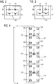
- FIG. 4 is a further embodiment of a power converter in a so-called H-circuit for use in a device according to the invention shown in which the switching elements 10a ... 10i or 10a '... 10i', 11a ... 11i and 11a '.. .11i ', 12a ... 12i or 12a' ... 12i 'according to FIG. 2 are arranged to phase elements 27, 28, 29.
- Each of the phase elements 27, 28, 29 comprises two parallel branches, each with series-connected switching elements 10a ... 10i or 10a '... 10i', 11a ... 11i and 11a '... 11i', 12a .. .12i or 12a '... 12i'.
- the parallel branches are each about two in FIG.
- the central connection line has in each case a phase connection 30, 31, 32 for connection to two phases of a connected alternating voltage.
- the phase terminals 30, 31, 32 are shown schematically as secondary-side terminals of transformers 30, 31, 32, at the primary side, not shown, the respective AC voltage is tapped or applied.
- the respective phase elements 27, 28, 29 connected in series with each other are connected in parallel with capacitors 33, 34, 35. If the arrangement shown operated to generate an AC voltage, an AC voltage is fed into a phase of a polyphase AC voltage by each phase element from the DC side coupled DC voltage by the individual switching elements suitable be controlled.
- the capacitors 33, 34, 35 serve for additional stabilization and smoothing and are only optional.
- This arrangement acts according to the principle of a voltage sourced converter and generates a three-phase alternating voltage from the DC voltage impressed or generated by the power converter itself DC voltage.
- the arrangement can of course also be used as a converter for converting a three-phase AC voltage into a DC voltage and vice versa.
- FIG. 5 shows a power converter with a parallel connection of the phase elements 27, 28, 29, are realized with the higher transmission currents compared to the series circuit of Fig. 4 ,
- the phase elements in this embodiment are connected, for example, by means of coils 36, 37, 38 and 36 ', 37', 38 'to the bipolar DC circuit to which a transmission line, cable or GIL or any combination thereof can be connected.
- FIG. 6 another embodiment of a device according to the invention for electric power transmission 39 is shown schematically.
- the device comprises a power converter 40, which is connected to a transmission line 41 of a transmission network, wherein the power converter 40 is connected on the DC side with a capacitor 52 and an optional DC voltage source 42.
- the transmission line 41 is part of a power supply network with load connection as a transmission network.
- control and regulation unit 43 To control and regulate the power converter is used in addition to other means for controlling the device according to the invention shown a control and regulation unit 43, to which a measured by a current measuring unit 44 detected alternating current I AC and obtained by means of a voltage measuring unit 45 measuring AC voltage U AC transmitted and given in this with Setpoint values are compared in order to control the AC voltage of the transmission line 41 dynamically and phase-adjusted by means of suitable control methods.
- AC voltage includes any time waveforms of the voltage applied to the transmission line 41 as a transmission network, and is not limited to sinusoidal or harmonic voltage waveforms.
- the power converter 40 is connected to the transmission line 41 via an optional coil 46 and also an optional transformer 47.
- a reactive and / or active power control or dynamic control functions such as damping of power oscillations and / or subsynchronous resonances and / or sub- and / or supersub-harmonics and / or voltage balancing by means of active coupling of a dynamic in magnitude and / or Phase variable voltage allows.
- the power converter 40 has figuratively not shown phase elements as in FIG. 1 shown inverter 4, 6 or as in the FIGS. 4 or 5 illustrated power converter on.
- Further assemblies for compensation 48, 49 with fixed elements and switchable or controllable power semiconductors 50, 51 are also connected to the transmission line 41.
- the passive components of the compensation modules 48, 49 can be made of any combination of coils, capacitors, resistors and arresters, and / or individual elements thereof.
- an assembly of the assembly 49 with a resistor is advantageous, so that a switched or controlled braking resistor for reducing an active power excess is realized on the transmission line 41.
- Such active power surplus can lead to harmful overvoltages when switching off connected to the transmission line 41 loads or HVDC systems.
- the assembly 49 has at least one arrester.
- the connection of the power converter 40 and the modules for compensation 48, 49th with the polyphase transmission line 41 can be made via the transformer 47 or via an impedance or directly.
- Such compensation and control elements are known as such under the name FACTS.
- FACTS compensation and control elements
- the AC voltage generated in the power converter 40 is actively connected to the transmission line 41.
- the power converter 40 is activated as a function of the transmission requirements, so that the coupled-in signal can be adapted in fine graduation to the transmission requirements.
- the power semiconductors 50, 51 and mechanical switches such as circuit breakers can be used.
- FACTS for example a static synchronous compensator (STATCOM), with serial coupling to the transmission line a Static Synchronous Series Compensator (S3C) or, when combining parallel and series coupling, a Unified Power Flow Controller (FIG. UPFC).
- STATCOM static synchronous compensator
- S3C Static Synchronous Series Compensator
- FACTC Unified Power Flow Controller
- Deviating from the illustrated three-phase AC voltage networks or the three-phase transmission line 41 shown in the invention can also be connected to one, two, - or multi-phase AC networks or transmission lines by means of each appropriate connection means.
- the device is suitable according to FIG. 1 , Both in the bridge circuit shown there and in the variant with converters with H-circuit according to the FIG. 4 . 5 in a special way to the known HVDC multiterminal operation, ie for high-voltage direct current transmission with three or more converters, wherein the power converter by means of a transmission line, which is realized as a cable or a gas-insulated transmission line, or directly connected to form a so-called close coupling.
- a transmission line which is realized as a cable or a gas-insulated transmission line, or directly connected to form a so-called close coupling.
- the capacitors of in FIG. 1 shown circuitry 9, 9 ', the capacitors 26 according to the FIGS. 2 and 3 , the capacitors 33, 34, 35 according to FIG. 4 and the capacitors of the FIGS. 6 including the capacitor 52 can be arbitrarily combined with energy storage such as flywheel, batteries, super-caps or the like or replaced by these energy storage.
- energy storage such as flywheel, batteries, super-caps or the like or replaced by these energy storage.
- the energy stores are arranged parallel to or instead of said capacitors.
- a spatially concentrated arrangement in a common assembly such as in the circuit 9 as well as a distributed arrangement of the energy storage, so a spatial distribution to different components possible.
Abstract
Um eine Vorrichtung für die Elektroenergieübertragung (1,39) mit mindestens einem Stromrichter (4,6,40), wobei jeder Stromrichter (4,6,40) Phasenelemente (10,11,12,13,14,15,27,28,29) aufweist, welche jeweils über eine Anordnung von Schaltelementen (10a...10i, 11a...11i, 12a...12i, 13a...13i, 14a...14i, 15a...15i, 10a'... 10i', 11a'...11i', 12a'...12i') verfügen, die jeweils mindestens zwei abschaltbare Leistungshalbleiter (22,23) und mindestens zwei jeweils dazu parallel geschaltete Freilaufdioden (24,25) und Energiespeichermittel (26) umfassen, bereitzustellen, mit der Übertragungseigenschaften in oder zwischen Energieverteilungsnetzen verbessert werden, werden Mittel (16, 17, 18, 19, 43, 44, 45) zum Regeln des Stromrichters, so dass der Nullphasenwinkel, die Amplitude und/oder die Augenblickswerte einer Wechselspannung eines mit der Vorrichtung verbindbaren Übertragungsnetzes und/oder die Gleichspannung und der Gleichstrom einer Gleichspannungsleitung, welche wenigstens einen der Stromrichter mit einem weiteren Stromrichter verbindet, steuerbar sind.To a device for the electrical energy transmission (1,39) with at least one power converter (4,6,40), wherein each power converter (4,6,40) phase elements (10,11,12,13,14,15,27,28 , 29) each having an array of switching elements (10a ... 10i, 11a ... 11i, 12a ... 12i, 13a ... 13i, 14a ... 14i, 15a ... 15i, 10a '... 10i', 11a '... 11i', 12a '... 12i'), each having at least two turn-off power semiconductors (22,23) and at least two respectively parallel-connected freewheeling diodes (24,25) and Energy storage means (26) comprise providing to improve the transmission characteristics in or between power distribution networks, means (16, 17, 18, 19, 43, 44, 45) for controlling the power converter, so that the zero phase angle, the amplitude and / or the instantaneous values of an AC voltage of a transmission network which can be connected to the device and / or the DC voltage and the DC current of a DC voltage line which comprises at least one d he power converter with another power converter connects, are controllable.
Description
Die Erfindung betrifft eine Vorrichtung für die Elektroenergieübertragung mit mindestens einem Stromrichter, wobei jeder Stromrichter Phasenelemente aufweist, welche jeweils über eine Anordnung von Schaltelementen verfügen, die jeweils mindestens zwei abschaltbare Leistungshalbleiter und mindestens zwei jeweils dazu parallel geschaltete Freilaufdioden und Energiespeichermittel umfassen.The invention relates to a device for the transmission of electrical energy with at least one power converter, each converter comprises phase elements, each having an array of switching elements, each comprising at least two turn-off power semiconductor and at least two each connected in parallel freewheeling diodes and energy storage means.
Bekannte Vorrichtungen dieser Gattung weisen beispielsweise zwei gleichspannungsseitig verbundene Stromrichter auf, um elektrische Energie zwischen zwei elektrisch getrennten, asynchronen oder miteinander verbundenen, synchronen Wechselspannungsnetzen zu übertragen und diese Übertragung gezielt zu steuern. Eine solche Steuerung ist notwendig, da beispielsweise in den Wechselspannungsnetzen lokale Überlastungen oder ungleiche Lastverteilungen auftreten können. Die Überlastungen können dann durch die geregelte Energieübertragung ausgeglichen werden. Solche und eine Reihe weiterer Vorrichtungen sind als so genannte HGÜ-Anlagen und FACTS bekannt. In Stromrichtern dieser HGÜ-Anlagen und FACTS werden Leistungshalbleiter, wie beispielsweise Thyristoren, die in netzgeführter Technik wirken, oder abschaltbare Leistungshalbleiter, wie beispielsweise so genannte Insulated Gate Bipolar Transistoren (IGBT), eingesetzt, die bei selbstgeführten Topologien zum Einsatz kommen. Bei so genannten Voltage Sourced Convertern (VSC) mit abschaltbaren Leistungshalbleitern ist ein Energiezwischenspeicher, in der Regel ein Kondensator, notwendig. Nachteilig bei Anordnungen mit selbstgeführten Stromrichtern und einem Kondensator als Energiezwischenspeicher ist die Begrenzung der Übertragungsleistung durch die Größe des verwendeten Kondensators. Im Fehlerfall kann ein extrem hoher Kurzschlussstrom zur Zerstörung der Anlage führen. Mit einer derartigen Anordnung werden daher bislang in der Praxis nur Übertragungsspannungen bis zu etwa ±150 kV und Übertragungsleistungen von etwa 300 bis 500 Megawatt erreicht.Known devices of this type have, for example, two rectifiers connected on the DC side in order to transmit electrical energy between two electrically separated, asynchronous or interconnected, synchronous AC voltage networks and to control this transmission in a targeted manner. Such a control is necessary since, for example, local overloads or unequal load distributions can occur in the AC voltage networks. The overloads can then be compensated by the regulated energy transfer. Such and a number of other devices are known as so-called HVDC systems and FACTS. In converters of these HVDC systems and FACTS are power semiconductors, such as thyristors, which act in network-guided technology, or turn-off power semiconductors, such as so-called Insulated Gate Bipolar Transistors (IGBT), used in self-guided topologies used. Voltage sourced converters (VSC) with turn-off power semiconductors require an energy buffer, usually a capacitor. A disadvantage of arrangements with self-commutated converters and a capacitor as an energy buffer is the limitation of the transmission power by the size of the capacitor used. In the event of a fault, an extremely high short-circuit current can destroy the system. With such an arrangement so far in practice only transmission voltages up to about ± 150 kV and transmission power of about 300 to 500 megawatts.
Aus der
Aufgabe der vorliegenden Erfindung ist es, eine Vorrichtung der eingangs genannten Art auszubilden, mit der die Übertragungseigenschaften in oder zwischen Energieverteilungsnetzen verbessert sind.Object of the present invention is to provide a device of the type mentioned, with which the transmission properties are improved in or between power distribution networks.
Die Aufgabe wird erfindungsgemäß durch eine Vorrichtung mit den Merkmalen des Patentanspruchs 1 gelöst.The object is achieved by a device having the features of claim 1.
Erfindungsgemäß sind demnach Mittel zum Regeln des Stromrichters vorgesehen, so dass der Nullphasenwinkel, die Amplitude und/oder die Augenblickswerte einer Wechselspannung eines mit der Vorrichtung verbindbaren Übertragungsnetzes und/oder die Gleichspannung und der Gleichstrom einer Gleichspannungsleitung, welche wenigstens einen der Stromrichter mit einer Gleichspannungsquelle verbindet steuerbar sind.According to the invention means are provided for controlling the power converter, so that the zero phase angle, the amplitude and / or the instantaneous values of an AC voltage connectable to the device transmission network and / or the DC voltage and the DC current of a DC voltage line, which connects at least one of the power converter with a DC voltage source are controllable.
Erfindungsgemäß ist eine Vorrichtung mit Stromrichtern bereitgestellt, die jeweils mehrere einzeln schaltbare Energiespeichermittel aufweisen. Über die Mittel zum Regeln können die Eigenschaften eines solchen Stromrichters im Bereich der Energieübertragung und -verteilung und insbesondere bei der Blindleistungskompensation und der Gleichstromübertragung eingesetzt werden, wo die Eigenschaften eines solchen Stromrichters besonders vorteilhaft sind. So dient die erfindungsgemäße Vorrichtung beispielsweise zum Erhöhen der Stabilität des Übertragungsnetzes, an welches die erfindungsgemäße Vorrichtung anschließbar ist. Zusätzlich zur Verbesserung der Netzstabilität kann jedoch auch die Stromqualität der Energieübertragung optimiert werden, wobei der Begriff der Stromqualität hier die Versorgungssicherheit und die Spannungsqualität umfasst. Hierzu wird die von dem Stromrichter erzeugte Spannung an eine Übertragungsleitung des Übertragungsnetzes parallel aufgeschaltet oder seriell in diese eingekoppelt, so dass der Lastfluss in dem Übertragungsnetz wie gewünscht verändert ist. Zum phasengenauen parallelen Aufschalten oder seriellen Einkoppeln der Spannung sind in dem Übertragungsnetz zweckmäßigerweise Geräte zum Erfassen der Wechselspannung und des Wechselstromes vorgesehen, deren Messwerte einer Regelungseinheit der erfindungsgemäßen Vorrichtung zugeführt werden, welche anhand eines Vergleichs der gemessenen Werte mit vorgegebenen Sollwerten eine Regelung des Stromrichters ermöglicht. Die Mittel zum Regeln umfassen neben einer oder mehreren solcher Regelungseinheiten Messgeräte zum Erfassen von Messgrößen, auf der oder den Regelungseinheiten ablaufende Software, Kommunikationseinrichtungen und dergleichen. Steuerbare Größen der Regelung sind beispielsweise die Wechselspannung und/oder der Wechselstrom des Übertragungsnetzes. Das Übertragungsnetz weist eine oder mehrere Phasen auf. Unter Wechselspannung ist im Rahmen der beanspruchten Erfindung sowohl eine Grundschwingungsgröße als auch ein zeitlich beliebig veränderlicher Spannungsverlauf zu verstehen. So werden im Falle von im Wesentlichen sinusförmigen Wechselspannungen Nullphasenwinkel und Amplitude der Wechselspannung des Übertragungsnetzes bevorzugt geregelt. Zur Regelung anderer zeitlicher Verläufe der Wechselspannung dienen bevorzugt die Augenblickswerte der Wechselspannung, die auch als Momentanwerte bezeichnet werden können. Unter dem Begriff Nullphasenwinkel ist die Phasendifferenz zwischen der Wechselspannung und einer Bezugsgröße zu verstehen, die von den jeweils an die erfindungsgemäße Vorrichtung gestellten Anforderungen abhängig ist. Nur beispielsweise sei daher hier der Wechselstrom des Übertragungsnetzes am Anschlusspunkt als Bezugsgröße genannt.According to the invention, a device with power converters is provided which each have a plurality of individually switchable energy storage means. By means of the regulating means, the characteristics of such a power converter can be used in the area of energy transmission and distribution, and in particular in reactive power compensation and direct current transmission, where the characteristics of such a power converter are particularly advantageous. For example, the device according to the invention serves to increase the stability of the transmission network to which the device according to the invention can be connected. However, in addition to improving grid stability, the power quality of the power transmission can also be improved be optimized, the term of power quality here includes the security of supply and the voltage quality. For this purpose, the voltage generated by the power converter is connected in parallel to a transmission line of the transmission network or serially coupled into this, so that the load flow in the transmission network is changed as desired. For phase-parallel connection or serial connection of the voltage, devices for detecting the alternating voltage and the alternating current are expediently provided in the transmission network, the measured values of which are fed to a control unit of the device according to the invention, which allows control of the converter based on a comparison of the measured values with predetermined set values. The means for controlling comprise, in addition to one or more such control units, measuring devices for detecting measured variables, software running on the control unit or units, communication devices and the like. Controllable variables of the control are, for example, the alternating voltage and / or the alternating current of the transmission network. The transmission network has one or more phases. In the context of the claimed invention, AC voltage is to be understood as meaning both a fundamental vibration variable and a voltage curve that varies as desired over time. Thus, in the case of essentially sinusoidal alternating voltages, zero phase angle and amplitude of the alternating voltage of the transmission network are preferably regulated. To regulate other time profiles of the alternating voltage, the instantaneous values of the alternating voltage, which can also be referred to as instantaneous values, are preferably used. The term zero phase angle is to be understood as the phase difference between the alternating voltage and a reference variable, which depends on the respective requirements imposed on the device according to the invention. For example, therefore, here is the AC of the transmission network at the connection point called as a reference.
Der Stromrichter ist über eine Gleichspannungsleitung auch mit einer Gleichspannungsquelle verbunden. Bei der Gleichspannungsquelle handelt es sich um einen weiteren Stromrichter. Beide Stromrichter arbeiten dann als gleichspannungsseitig miteinander verbundene Umrichter einer Gleichstromübertragungsanlage, wobei die Regelgrößen die Gleichspannung und/oder der Gleichstrom der Gleichstromleitung und/oder die Wechselspannung des Übertragungsnetzes sind. Die Gleichspannung und der Gleichstrom werden an jedem Stromrichter erfasst und einer dem Stromrichter jeweils zugeordneten Regelungseinheit zugeführt. Durch die Regelung lässt sich die zu übertragende Wirkleistung und/oder Blindleistung und/oder deren jeweiliger Anteil bestimmen. Die Sollparameter werden im Falle von entfernt voneinander aufgestellten Stromrichtern durch eine zweckmäßige Datenfernübertragung zwischen den Stromrichtern übertragen. Die Stromrichter einer solchen Gleichstromfernübertragungsanlage sind mehrere Kilometer entfernt voneinander aufgestellt.The power converter is also connected via a DC voltage line to a DC voltage source. For the DC voltage source it is another power converter. Both converters then work as DC side interconnected inverter a DC transmission system, the control variables are the DC voltage and / or the DC current of the DC line and / or the AC voltage of the transmission network. The DC voltage and the DC current are detected at each power converter and supplied to the power converter respectively associated control unit. By the regulation, the active power to be transmitted and / or reactive power and / or their respective component can be determined. The target parameters are transmitted in the case of remotely located power converters by a convenient remote data transmission between the converters. The power converters of such a DC remote transmission system are located several kilometers away from each other.
Der Aufbau und die Funktion der Schaltelemente sind in der
Die Stromrichter der Vorrichtung sind erfindungsgemäß modular aufgebaut. Der modulare Aufbau erfolgt durch Phasenelemente, die wiederum in Schaltelemente untergliedert sind. Die Schaltelemente sind entweder identisch und insbesondere mit identischen Energiespeichermitteln aufgebaut, die somit über die gleiche Speicherkapazität verfügen. Abweichend hiervon kommen jedoch auch Kombinationen mit unterschiedlicher Auslegung der Kapazität im Rahmen der Erfindung in Betracht.The power converters of the device according to the invention are modular. The modular structure is performed by phase elements, which in turn are subdivided into switching elements. The switching elements are either identical and in particular constructed with identical energy storage means, which thus have the same storage capacity. Deviating from this, however, combinations with different design of the capacitance come within the scope of the invention into consideration.
Bei einer zweckmäßigen Weiterentwicklung der Erfindung sind die Schaltelemente eines Phasenelementes in Reihe geschaltet, wobei die Schaltelemente in geradzahliger Anzahl vorgesehen sind, und ein Last- oder Netzanschluss an der Reihenschaltung der Schaltelemente mittig angeordnet ist. Durch die Reihenschaltung mehrerer Schaltelemente und eine entsprechende Ansteuerung der einzelnen Schaltelemente ist eine Spannungsaussteuerung mit einer noch feineren Abstufung möglich. Bei einem mittigen Last- oder Netzanschluss sind die Schaltelemente einer Seite der Reihenschaltung beispielsweise in einem weiter oben beschriebenen ersten Zustand und die Schaltelemente der anderen Seite im ebenfalls weiter oben beschriebenen zweiten Zustand oder umgekehrt. Mit diesen Ansteuerungen werden am Phasenelement maximale Spannungswerte erreicht. Werden eines oder mehrere Schaltelemente auf den jeweiligen Seiten in den zweiten Zustand gesteuert, ergibt sich die Abstufung der Spannung mit einer Stufenhöhe der Spannung der einzelnen Schaltelemente.In an expedient further development of the invention, the switching elements of a phase element are connected in series, wherein the switching elements are provided in an even number, and a load or mains connection is arranged centrally on the series connection of the switching elements. By the series connection of a plurality of switching elements and a corresponding control of the individual switching elements, a voltage modulation with an even finer gradation is possible. In the case of a central load or mains connection, the switching elements of one side of the series connection are, for example, in a first state described above and the switching elements of the other side are in the second state likewise described above or vice versa. With these activations, maximum voltage values are achieved at the phase element. If one or more switching elements are controlled on the respective sides in the second state, the gradation of the voltage results with a step height of the voltage of the individual switching elements.
Im Rahmen der Erfindung sind jedoch auch Phasenelemente mit ungerader Anzahl an Schaltelementen und/oder Phasenelementen mit einem nicht-mittigen Last- oder Netzanschluss möglich. Die einzelnen Schaltelemente sind beispielsweise für gleiche oder ungleiche Spannungen ausgelegt und zweckmäßigerweise binär oder anderweitig, unterschiedlich gestuft, wodurch eine feinere Abstimmung bei gleicher Anzahl der Schaltelemente ermöglicht ist als im Falle einer Auslegung für gleiche Spannungen.In the context of the invention, however, phase elements with an odd number of switching elements and / or phase elements with a non-central load or mains connection are also possible. The individual switching elements are designed, for example, equal or unequal voltages and expediently binary or otherwise, different degrees, whereby a finer tuning is possible with the same number of switching elements as in the case of a design for equal voltages.
In einer Weiterentwicklung umfasst das Phasenelement eine Anordnung mit zwei Parallelzweigen mit jeweils einer geraden Anzahl von Schaltelementen in Reihenschaltung. Durch die Parallelschaltung von zwei Zweigen mit jeweils einer Reihenschaltung von Schaltelementen ist die Abstufungsfeinheit der vom Stromrichter generierbaren Spannung noch weiter erhöht.In a further development, the phase element comprises an arrangement with two parallel branches, each with an even number of switching elements in series connection. Due to the parallel connection of two branches, each with a series circuit of switching elements, the grading fineness of the voltage which can be generated by the power converter is increased even further.
Gemäß einer diesbezüglich zweckmäßigen Weiterentwicklung sind wenigstens zwei Parallelzweige mittels einer Transformatorwicklung miteinander verbunden. Hievon abweichend sind wenigstens zwei Parallelzweige galvanisch über eine Parallelzweigverbindung miteinander verbunden. Die galvanische Verbindung mittels einer Parallelzweigverbindung ermöglicht eine kostengünstige Bauweise eines Transformators, der zum Anschluss der erfindungsgemäßen Vorrichtung an ein Übertragungsnetz und/oder an eine Gleichspannungsleitung dient.According to an expedient further development, at least two parallel branches are connected to one another by means of a transformer winding. Deviating from this, at least two parallel branches are galvanically connected to one another via a parallel branch connection. The galvanic connection by means of a parallel branch connection enables a cost-effective design of a transformer, which serves to connect the device according to the invention to a transmission network and / or to a DC voltage line.
In zweckmäßiger Fortbildung sind mehrere Phasenelemente eines Stromrichters parallel miteinander verbunden. Dabei bilden die Phasenelemente eine Brückenschaltung aus. Der Stromrichter wirkt wie ein als solcher bekannter so genannter Voltage Sourced Converter (VSC) und ist somit in vorteilhafter Weise an das Übertragungsnetz zum Einkoppeln einer steuerbaren mehrphasigen Wechselspannung zur Blind- und/oder Wirkleistung anschließbar. Dabei generiert der Stromrichter eine mehrphasige Wechselspannung. Durch die Regelungsmittel kann wahlweise der Nullphasenwinkel und/oder die Amplitude der in das Übertragungsnetz einzukoppelnden Wechselspannung und zwar unabhängig voneinander beeinflusst werden. Ein solcher Stromrichter kann daher beispielsweise auch als aktives Filterelement anstelle von oder kombiniert mit passiven Filtern, wie beispielsweise RC-Gliedern, zur aktiven Filterung von Spannungsverzerrungen im Frequenzbereich unter und/oder oberhalb der Netzfrequenz (sub-, supersub-Harmonische) und/oder zur Kompensation von Spannungsunsymmetrien verwendet werden. Hierbei wird eine solche Spannung vom Stromrichter eingekoppelt, dass die Spannungsabweichungen von der Sinusform beispielsweise durch negative Interferenz ausgelöscht werden.In appropriate training several phase elements of a power converter are connected in parallel. The phase elements form a bridge circuit. The power converter acts like a so-called voltage sourced converter (VSC) known as such and can thus be advantageously connected to the transmission network for coupling in a controllable multiphase AC voltage to the reactive and / or active power. The power converter generates a multiphase AC voltage. By the control means may optionally be the zero phase angle and / or the amplitude of the in the Transmission network to be coupled AC voltage and that can be influenced independently. Such a converter can therefore also be used, for example, as an active filter element instead of or combined with passive filters, such as RC elements, for the active filtering of voltage distortions in the frequency range below and / or above the line frequency (sub-, supersub-harmonics) and / or Compensation of voltage unbalance can be used. In this case, such a voltage is coupled in by the power converter that the voltage deviations from the sinusoidal form are extinguished, for example, by negative interference.
Ferner kann ein solcher Voltage Sourced Converter auch bei der Gleichstromübertragung als Umrichter verwendet werden. Der Stromrichter oder besser Umrichter umfasst dann beispielsweise drei parallel miteinander verbundene Phasenelemente in bekannter Brückenschaltung. Auch eine Anordnung mit zwei parallel geschalteten Phasenelementen bietet eine einfache Möglichkeit zur Ausbildung eines Umrichters zur Gleichstromübertragung zum Anschluss an ein Übertragungsnetz mit nur einer einzigen Phase, beispielsweise über einen Koppeltransformator, oder an ein Übertragungsnetz mit mehreren Phasen. Der Begriff Gleichstromübertragung umfasst im Rahmen der vorliegenden Erfindung sowohl die Hochspannungsgleichstromübertragung (HGÜ) als auch Mittelspannungsgleichstromübertragung (MGÜ) und Niederspannungsgleichstromübertragung (NGÜ).Furthermore, such a voltage source converter can also be used as a converter in DC transmission. The converter or better converter then comprises, for example, three phase elements connected in parallel in a known bridge circuit. An arrangement with two phase elements connected in parallel also offers a simple possibility of forming a converter for DC transmission for connection to a transmission network with only a single phase, for example via a coupling transformer, or to a transmission network with several phases. The term DC transmission in the context of the present invention includes both the high-voltage direct current transmission (HVDC) and medium-voltage direct current transmission (MGÜ) and low-voltage direct current transmission (NGÜ).
In einer anderen Ausführungsform sind mehrere Phasenelemente in Reihe miteinander verbunden. Vorteilhafterweise werden Phasenelemente mit zwei Parallelzweigen mit jeweils mehreren Schaltelementen miteinander in Reihe verbunden. Eine solche Anordnung wirkt ebenfalls als Voltage Sourced Converter und kann beispielsweise als Umrichter in einer Gleichstromübertragungsanlage wirken. Dabei ermöglicht die Reihenschaltung bei einer vorgegebenen Leistung die Übertragung mit einer höheren Gleichspannung, also mit kleinerem Strom und daher geringeren Verlusten.In another embodiment, a plurality of phase elements are connected in series. Advantageously, phase elements with two parallel branches, each having a plurality of switching elements, are connected to one another in series. Such an arrangement also acts as a voltage sourced converter and may, for example, act as a converter in a DC transmission system. The series connection allows for a given power transmission with a higher DC voltage, ie with smaller current and therefore lower losses.
In vorteilhafter Weiterbildung sind parallel zu den Phasenelementen Energiespeichermittel angeordnet. Solche zusätzlichen Energiespeichermittel werden zum Zweck einer weiteren Glättung und Stabilisierung eingesetzt.In an advantageous embodiment, energy storage means are arranged parallel to the phase elements. Such additional energy storage means are used for the purpose of further smoothing and stabilizing.
In einer weiteren Ausgestaltung weist jedes Phasenelement mindestens eine Impedanz auf oder ist über mindestens eine Impedanz mit einem anderen Phasenelement verbunden. Solche Impedanzen, im einfachsten Fall ausgebildet als Spulen, wirken in vorteilhafter Weise zur Begrenzung eines Kreisstromes, der zwischen den einzelnen Phasenelementen beispielsweise aufgrund von Spannungsschwankungen oder Spannungsunsymmetrien auftreten kann. Außerdem können die Impedanzen so ausgelegt werden, dass in Fehlerfällen die Stromanstiegssteilheit und/oder die Stromamplitude begrenzt wird. Die Impedanz ist dabei beispielsweise entweder mit dem Phasenelement oder mit einzelnen Schaltelementen eines Phasenelementes in Reihe geschaltet oder in die Schaltelemente integriert, z.B. in vorteilhafter Modulbauweise.In a further embodiment, each phase element has at least one impedance or is connected to another phase element via at least one impedance. Such impedances, in the simplest case embodied as coils, advantageously act to limit a circulating current which can occur between the individual phase elements, for example due to voltage fluctuations or voltage imbalances. In addition, the impedances can be designed so that in case of errors, the current rise rate and / or the current amplitude is limited. The impedance is, for example, connected in series with either the phase element or with individual switching elements of a phase element or integrated into the switching elements, e.g. in an advantageous modular design.
In einer bevorzugten Ausführungsform ist mindestens ein Stromrichter parallel zum Übertragungsnetz anschließbar. Eine solche Anordnung dient zur so genannten Parallelkompensation für die Blind- und/oder Wirkleistungssteuerung und entfaltet beispielsweise dynamische Regelfunktionen zur Dämpfung von unerwünschten Leistungspendelungen und/oder subsynchronen Resonanzen und/oder sub- bzw. supersub-Harmonischen. Die vorteilhafte Weiterentwicklung dient beispielsweise auch zur Spannungssymmetrierung.In a preferred embodiment, at least one power converter can be connected in parallel to the transmission network. Such an arrangement is used for so-called parallel compensation for the reactive and / or active power control and unfolds, for example, dynamic control functions for damping unwanted power oscillations and / or subsynchronous resonances and / or sub and supersub harmonics. The advantageous further development also serves, for example, for voltage balancing.
Besonders vorteilhaft gegenüber bekannten Parallelkompensationsvorrichtungen ist bei der erfindungsgemäß weiterentwickelten Vorrichtung, dass durch die bereits oben beschriebene Reihenschaltung der Schaltelemente eine fein abstufbare Wechselspannung in die Übertragungsleitung eingekoppelt werden kann, wobei die Energie zur Erzeugung der Wechselspannung in den verteilten Energiespeichermitteln der einzelnen Schaltelemente gespeichert ist, im Gegensatz zu bekannten Vorrichtungen, bei denen ein einzelner Kondensator als Energiespeicher dient und der aufgrund seiner Größe als begrenzendes Element für die Übertragungsspannung und Leistung der Vorrichtung wirkt. Mit der erfindungsgemäßen Vorrichtung mit Energiespeichermitteln in jedem Schaltelement ist die einzukoppelnde Spannung daher feiner einstellbar.Particularly advantageous over known parallel compensation devices is in the inventively further developed device that a finely graded AC voltage can be coupled into the transmission line through the above-described series connection of the switching elements, wherein the energy for generating the AC voltage in the distributed energy storage means of the individual switching elements is stored, in contrast to known devices, in which a single capacitor serves as an energy storage and acts due to its size as a limiting element for the transmission voltage and performance of the device. With the device according to the invention with energy storage means in each switching element, the voltage to be coupled in is therefore more finely adjustable.
In einer weiteren Ausgestaltung ist mindestens ein Stromrichter in Reihe zum Übertragungsnetz anschließbar. Ein solcher Anschluss dient ebenfalls zur Blind- und/oder Wirkleistungssteuerung des Übertragungsnetzes, einschließlich der bereits beschriebenen dynamischen Regelfunktionen, durch aktive Aufschaltung und/oder Einkopplung einer dynamisch in Betrag und/oder Phase veränderlichen Spannung. Vorteilhafterweise umfasst die erfindungsgemäße Vorrichtung mehrere Stromrichter, von denen einer parallel und einer in Reihe zum Übertragungsnetz geschaltet ist. Die Blind- und/oder Wirkleistungssteuerung des Übertragungsnetzes oder auch die vorstehend beschriebenen dynamischen Regelfunktionen werden durch eine aktive Einkopplung von zwei dynamisch in Betrag und/oder Phase veränderlichen Spannungen verbessert. Das Übertragungsnetz ist beispielsweise eine einphasige oder eine mehrphasige Übertragungsleitung.In a further embodiment, at least one power converter can be connected in series with the transmission network. Such a connection is also used for blind and / or active power control of the transmission network, including the dynamic control functions already described, by active connection and / or coupling a dynamically variable in magnitude and / or phase voltage. Advantageously, the device according to the invention comprises a plurality of power converters, one of which is connected in parallel and one in series with the transmission network. The reactive and / or active power control of the transmission network or the dynamic control functions described above are improved by an active coupling of two dynamically variable in magnitude and / or phase voltages. The transmission network is, for example, a single-phase or a multi-phase transmission line.
Der weitere beziehungsweise zweite Stromrichter kann in diesem Fall als Gleichrichter wirken, wobei der Gleichstrom über die Gleichspannungsleitung zum ersten Stromrichter geführt wird. Der erste Stromrichter oder besser Umrichter dient dann zur Umwandlung einer Gleichspannung in eine Wechselspannung. Die Wirkungsweise der Stromrichter als Gleichrichter oder Wechselrichter ist jedoch beliebig wählbar.The further or second power converter can act as a rectifier in this case, wherein the direct current is fed via the DC voltage line to the first power converter. The first power converter or better inverter is then used to convert a DC voltage into an AC voltage. However, the mode of action of the power converter as a rectifier or inverter is arbitrary.
Die Gleichspannungsleitung ist zumindest zum Teil eine gasisolierte Übertragungsleitung, ein Kabel und/oder eine Freileitung. Selbstverständlich sind im Rahmen der Erfindung auch Kombinationen dieser Leitungen möglich. Der besondere Vorteil von gasisolierten Übertragungsleitung, GIL, gegenüber einem Kabel, auch in Kombination mit einer Freileitung, ist die bessere Beherrschbarkeit dynamischer Regel- und Schutzfunktionen auf Grund der geringeren Ladekapazität der gasisolierten Leitung. Eine auf diese Weise weiterentwickelte erfindungsgemäße Vorrichtung dient beispielsweise zur Gleichstromfernübertragung, um aus einphasigen oder mehrphasigen Wechselspannungen mittels eines ersten Gleichrichters eine Gleichspannung zu erzeugen. Die Gleichspannung wird an den zweiten Stromrichter oder Umrichter übertragen. Die Gleichspannungsübertragung erfolgt grundsätzlich mit einer beliebig ausgestalteten Gleichspannungsleitung.The DC voltage line is at least partially a gas-insulated transmission line, a cable and / or an overhead line. Of course, combinations of these lines are possible within the scope of the invention. The particular advantage of gas-insulated transmission line, GIL, over one Cable, also in combination with an overhead line, is the better controllability of dynamic control and protection functions due to the lower charge capacity of the gas-insulated cable. A further development of the device according to the invention serves, for example, for remote DC transmission in order to generate a DC voltage from single-phase or multi-phase AC voltages by means of a first rectifier. The DC voltage is transmitted to the second converter or inverter. The DC voltage transmission takes place in principle with an arbitrarily configured DC voltage line.
Vorteilhaft bei der Verwendung eines erfindungsgemäßen Stromrichters mit drei parallelen miteinander verbundenen Phasenelementen ist, dass gleichspannungsseitig kein Energiespeichermittel mit der Gleichspannungsleitung zu verbinden ist, da die einzelnen Schaltelemente der Phasenelemente selbst über Energiespeichermittel verfügen, die sowohl als Energiespeicher als auch zur Spannungsglättung auf der Gleichspannungsseite dienen. Die Verwendung von drei parallel miteinander verbundenen Phasenelementen im zweiten Stromrichter ermöglicht durch die Schaltelemente mit Energiespeichermitteln die Erzeugung einer feiner abstufbaren mehrphasigen Wechselspannung beispielsweise zur Einkopplung in ein angeschlossenes Wechselspannungsnetz.Advantageous in the use of a power converter according to the invention with three parallel interconnected phase elements is that the DC voltage side no energy storage device is to be connected to the DC power line, since the individual switching elements of the phase elements themselves have energy storage means that serve both as energy storage and voltage smoothing on the DC side. The use of three parallel interconnected phase elements in the second power converter made possible by the switching elements with energy storage means the generation of a finer graduated multiphase AC voltage, for example for coupling into a connected AC voltage network.
Selbstverständlich sind im Rahmen der Erfindung auch Gleichspannungsübertragungsanlagen mit mehr als zwei Stromrichtern, also so genannte Multiterminals, realisierbar. Im Falle von Multiterminals, also Gleichstromübertragungsanlagen mit wenigstens drei Stromrichtern, ist die Gleichspannungsleitung im Rahmen der Erfindung optional. Mit andern Worten umfasst die Erfindung in einer Variante mit wenigstens drei Stromrichtern, die gleichspannungsseitig miteinander verknüpft sind, sowohl eine Gleichstromfernübertragungsanlage als auch eine Kurzkupplung.Of course, in the context of the invention, DC voltage transmission systems with more than two converters, so-called multi-terminals, can be realized. In the case of multi-terminals, ie DC transmission systems with at least three power converters, the DC voltage line is optional in the context of the invention. In other words, in a variant with at least three power converters, which are linked to one another on the DC voltage side, the invention comprises both a DC remote transmission system and a short coupling.
In einer zweckmäßigen Ausgestaltung umfasst der erste oder der zweite Stromrichter netzgeführte Leistungshalbleiter. Die Ausführung der Vorrichtung mit einem Stromrichter, der z.B. eine Brückenschaltung aus netzgeführten Leistungshalbleitern, beispielsweise Thyristoren oder im einfachsten Fall auch Dioden anstelle der abschaltbaren Leistungshalbleiter, aufweist, ermöglicht eine Reduzierung der Anlagenkosten.In an expedient embodiment, the first or the second power converter comprises mains-controlled power semiconductors. The implementation of the device with a power converter, e.g. a bridge circuit comprising line-guided power semiconductors, for example thyristors or, in the simplest case, diodes instead of the disconnectable power semiconductors, enables a reduction of the system costs.
In einer zweckmäßigen Weiterentwicklung ist die Gleichspannungsleitung ein- oder zweipolig. Zweipolige Gleichspannungsleitungen ermöglichen die Übertragung höherer Leistungen. Einpolige Gleichspannungsleitungen, die den Gleichstrom über die Erde oder bei Seekabelverbindungen über das Wasser zurückleiten, führen zu kostengünstigen Vorrichtungen. Ein-oder zweiphasige Übertragungsnetze auf der Wechselstromseite der erfindungsgemäßen Gleichstromfernübertragungsanlage ermöglichen den Anschluss an Sondernetze, z.B. zur Bahnstromversorgung. Selbstverständlich sind im Rahmen der Erfindung auch mehrpolige Gleichspannungsleitungen möglich.In an expedient further development, the DC voltage line is single-pole or double-pole. Two-pole direct voltage lines enable the transmission of higher power. Single-pole DC power lines, which conduct DC power over the ground or submarine cable connections across the water, provide cost-effective devices. Single- or two-phase transmission networks on the AC side of the DC remote transmission system according to the invention allow connection to special networks, e.g. to the traction power supply. Of course, multi-pole DC voltage lines are possible within the scope of the invention.
In einer weiteren Ausführungsform dieser Weiterentwicklung ist die Gleichspannungsleitung durch eine Impedanz ausgebildet, im einfachsten Fall eine Spule. Mit einer Spule als Gleichspannungsleitung kann beispielsweise eine als solche bekannte so genannte Kurzkupplung ausgebildet sein, wobei die Spule Funktionen wie Glättung, Strombegrenzung und/oder Begrenzung von Anstiegssteilheiten übernimmt.In a further embodiment of this further development, the DC voltage line is formed by an impedance, in the simplest case a coil. With a coil as a DC voltage line, for example, a so-called short coupling known as such may be formed, wherein the coil performs functions such as smoothing, current limiting and / or limiting slew rates.
In einer zweckmäßigen Ausgestaltung ist den Schaltelementen jeweils eine weitere Diode parallel geschaltet. Eine solche weitere Diode, beispielsweise eine an sich bekannte druckkontaktierte Diode wie eine Scheibenzellendiode oder eine in einem druckkontaktierten Elektronikmodul integrierte Diode, kann in einem Fehlerfall eines oder mehrerer Schaltelemente bei entsprechender Ansteuerung durch die Regelung eine Überbrückung eines defekten Schaltelementes ausbilden, wodurch ein Weiterbetrieb des Stromrichters ermöglicht wird. Dabei wird durch geeignete Ansteuerung der noch intakten Schaltelemente am defekten Schaltelement gezielt eine kurzzeitige. Überspannung aufgebaut, so dass die parallel geschaltete Diode durchlegiert und das defekte Schaltelement dauerhaft bis zum Austausch beim nächsten Wartungszyklus überbrückt bleibt. Des Weiteren kann auch die im Leistungshalbleiter integrierte Freilaufdiode eine derartige Überbrückungsfunktion des Schaltelements im Fehlerfall aufweisen.In an expedient embodiment, the switching elements each have a further diode connected in parallel. Such a further diode, for example a pressure-contact diode known per se, such as a disk cell diode or a diode integrated in a pressure-contacted electronic module, can, in the event of a fault of one or more switching elements with appropriate control by the regulation, form a bridging of a defective switching element, whereby a further operation of the power converter is possible. there By suitable control of the still intact switching elements on the defective switching element targeted a short-term. Overvoltage built so that the diode connected in parallel durchlegiert and the defective switching element remains permanently bridged until replacement during the next maintenance cycle. Furthermore, the free-wheeling diode integrated in the power semiconductor can also have such a bridging function of the switching element in the event of a fault.
Energiespeichermittel umfassen Energiespeicher wie beispielsweise Batterien, Schwungrad oder Super-Caps und Kondensatoren. Die Energiespeicher weisen eine im Vergleich zu Kondensatoren wesentlich höhere Energiedichte auf. Das hat den Vorteil, dass die Blind- und/oder Wirkleistungssteuerung einschließlich der bereits beschriebenen dynamischen Regelfunktionen auch bei einem längeren Spannungsab- oder Ausfall im Übertragungsnetz oder in der Gleichspannungsleitung verfügbar bleibt. Die Verwendung von Energiespeichermitteln mit einer hohen Energiedichte hat eine verbesserte Verfügbarkeit des Systems im Gefolge.Energy storage means include energy storage such as batteries, flywheel or super-caps and capacitors. The energy stores have a much higher energy density compared to capacitors. This has the advantage that the reactive and / or active power control including the dynamic control functions already described remains available even in the case of a longer voltage drop or failure in the transmission network or in the DC voltage line. The use of high energy density energy storage devices results in improved availability of the system.
Vorteilhafterweise sind die Energiespeichermittel zumindest teilweise Kondensatoren. Kondensatoren sind im Vergleich mit den derzeit bekannten Energiespeichern kostengünstig.Advantageously, the energy storage means are at least partially capacitors. Capacitors are inexpensive in comparison with the currently known energy storage.
In einer bevorzugten Ausführungsform erfolgt die Verbindung der Stromrichter mit der Gleichspannungsleitung mittels eines Energiespeichers. Bei Verwendung von Energiespeichern mit einer hohen Energiedichte ergibt eine solche Verbindung eine verbesserte Verfügbarkeit des Systems. Als Energiespeicher kommen auch bei dieser erfindungsgemäßen Weiterbildung beispielsweise die oben genannten Energiespeicher mit Ausnahme der Supercaps in Betracht. Die Anbindung der Energiespeicher an die Gleichspannungsleitung erfolg seriell oder parallel.In a preferred embodiment, the connection of the power converters with the DC voltage line takes place by means of an energy store. When using energy stores with a high energy density, such a connection results in an improved availability of the system. As an energy storage, for example, the above-mentioned energy storage with the exception of supercaps come into consideration in this inventive development. The connection of the energy storage devices to the DC voltage line succeeds serially or in parallel.
Vorteilhafterweise bildet die Vorrichtung eine Gleichstromübertragungsanlage und/oder ein so genanntes FACTS (Flexible AC Transmission System) aus und liefert dabei eine fein abgestufte Ausgangsspannung. Ein weiterer Vorteil ist die Übertragung einer Blind- und/oder Wirkleistung ohne aufwendige magnetische Kopplung. Dabei ist die erfindungsgemäße Vorrichtung vorteilhafterweise in modularer Bauweise ausgestaltet. Besonders bevorzugt wird die erfindungsgemäße Vorrichtung für die Gleichstromübertragung, und/oder zur Ausgestaltung eines so genannten Static Synchronous Compensators (STATCOM), eines Static Synchronous Series Compensators (S3C) oder eines Unified Power Flow Controllers (UPFC) verwendet.Advantageously, the device forms a DC transmission system and / or a so-called FACTS (Flexible AC Transmission System) and thereby provides a finely graduated Output voltage. Another advantage is the transmission of a reactive and / or active power without complex magnetic coupling. The device according to the invention is advantageously designed in a modular design. The device according to the invention is particularly preferably used for the DC transmission, and / or for the design of a so-called static synchronous compensator (STATCOM), a static synchronous series compensator (S3C) or a unified power flow controller (UPFC).
Die Erfindung betrifft ferner ein System mit einer Vorrichtung für die Elektroenergieübertragung der oben genannten Art. Auch hier ist das Übertragungsnetz einphasig oder weist mehrere Phasen auf. In der Regel ist das Übertragungsnetz eine dreiphasige Drehstromleitung, an welche die erfindungsgemäße Vorrichtung angeschlossen ist.The invention further relates to a system with a device for the transmission of electrical energy of the above type. Again, the transmission network is single-phase or has several phases. As a rule, the transmission network is a three-phase three-phase line to which the device according to the invention is connected.
Die Erfindung wird im Folgenden anhand von Ausführungsbeispielen mit Bezug auf Figuren der Zeichnung beschrieben, wobei gleiche Bezugszeichen auf Bauteile mit gleicher Wirkung verweisen. Es zeigen:
- Figur 1
- eine schematische Darstellung eines Ausführungsbeispiels der erfindungsgemäßen Vorrichtung;
- Figur 2
- eine Schaltungsanordnung eines Schaltelementes der Vorrichtung gemäß
Figur 1 ; - Figur 3
- ein weiteres Ausführungsbeispiel eines Schaltelementes der
Figur 1 ; - Figur 4
- eine beispielhafte schematische Darstellung eines Stromrichters mit einer Reihenschaltung von Phasenelementen der erfindungsgemäßen Vorrichtung;
Figur 5- eine beispielhafte schematische Darstellung eines Stromrichters mit einer Parallelschaltung von Phasenelementen der erfindungsgemäßen Vorrichtung;
Figur 6- ein Beispiel einer Vorrichtung zur Blindleistungskompensation.
- FIG. 1
- a schematic representation of an embodiment of the device according to the invention;
- FIG. 2
- a circuit arrangement of a switching element of the device according to
FIG. 1 ; - FIG. 3
- a further embodiment of a switching element of
FIG. 1 ; - FIG. 4
- an exemplary schematic representation of a power converter with a series circuit of phase elements of the device according to the invention;
- FIG. 5
- an exemplary schematic representation of a power converter with a parallel connection of phase elements of the device according to the invention;
- FIG. 6
- an example of a device for reactive power compensation.
In
Spannungswandler 16, 16' sowie Stromwandler 17, 17' sind zur Messung von Spannung beziehungsweise Strom sowohl am Gleichspannungszwischenkreis 5 als auch an den jeweiligen Wechselspannungsnetzen 2, 3 vorgesehen, wobei die wechselstromseitigen Spannungswandler und Stromwandler aus Gründen der Übersichtlichkeit figürlich nicht dargestellt sind. Die Ausgangssignale der Spannungswandler 16, 16' und der Stromwandler 17, 17' entsprechen den jeweils zu überwachenden Messgrößen der Hochspannungsbauteile. Die erfassten Größen werden schließlich als Messwerte an Regelungseinheiten 18, 19 der Vorrichtung übertragen. In den Regelungseinheiten 18, 19 werden die Signale unter Gewinnung von jeweils zugeordneten Abtastwerten abgetastet und die Abtastwerte unter Gewinnung digitaler Messwerte digitalisiert. Die gemessenen digitalisierten Messströme IDC und/oder IAC und die gemessenen digitalisierten Messspannungen UDC und/oder UAC werden jeweils mit vorgegebenen Sollwerten ISoll bzw. USoll verglichen. Mittel zum Regeln der Vorrichtung steuern auf der Grundlage von Steuerungs-und/oder Regelungsverfahren die Umrichter 4 und 6.
Zwischen die Verbindungen der Phasenelemente 10, 11, 12 bzw. 13, 14, 15, oder jeweils am mittigen Anschluss wenigstens eines der Schaltelemente 10a ... 10i, 11a ... 11i und 12a ... 12i bzw. 13a ... 13i, 14a ... 14i, 15a ... 15i können weitere figürlich nicht dargestellte Spulen angeordnet sein. Die Spulen begrenzen einen möglichen Kreisstrom zwischen den Phasenelementen.Between the connections of the
Die
In
Die
In
Zur Steuerung und Regelung des Stromrichters dient neben weiteren Mitteln zum Regeln der gezeigten erfindungsgemäßen Vorrichtung eine Steuerungs- und Regelungseinheit 43, an welche ein mittels einer Strommesseinheit 44 erfasster Messwechselstrom IAC und eine mittels einer Spannungsmesseinheit 45 gewonnene Messwechselspannung UAC übertragen und in dieser mit vorgegebenen Sollwerten verglichen werden, um mittels geeigneter Steuerungsverfahren die Wechselspannung der Übertragungsleitung 41 dynamisch und phasenangepasst zu steuern. Es sei an dieser Stelle nochmals darauf hingewiesen, dass der Begriff Wechselspannung beliebige Zeitverläufe der Spannung umfasst, mit der die Übertragungsleitung 41 als Übertragungsnetz beaufschlagt ist, und nicht auf sinusförmige oder harmonische Spannungsverläufe begrenzt ist.To control and regulate the power converter is used in addition to other means for controlling the device according to the invention shown a control and
Der Stromrichter 40 ist über eine optionale Spule 46 sowie einen ebenfalls optionalen Transformator 47 an die Übertragungsleitung 41 angeschlossen. Mit Hilfe des Stromrichters 40 sind eine Blind- und/oder Wirkleistungssteuerung oder dynamische Regelfunktionen wie Dämpfung von Leistungspendelungen und/oder subsynchronen Resonanzen und/oder sub- und/oder supersub-Harmonischen und/oder Spannungssymmetrierung mittels aktiver Einkopplung einer dynamisch in Betrag und/oder Phase veränderlichen Spannung ermöglicht.The
Der Stromrichter 40 weist figürlich nicht dargestellte Phasenelemente wie die in
Vorteilhafterweise verfügt die Baugruppe 49 über wenigstens einen Ableiter. Durch diese Ableiterbestückung ist eine vergleichbare Spannungsreduktion erzielbar. Die Verbindung des Stromrichters 40 und der Baugruppen zur Kompensation 48, 49 mit der mehrphasigen Übertragungsleitung 41 kann über den Transformator 47 oder über eine Impedanz oder auch direkt erfolgen. Derartige Kompensations- und Steuerungselemente sind als solche unter der Bezeichnung FACTS bekannt. Bei der hier gezeigten erfindungsgemäßen Vorrichtung wird die im Stromrichter 40 generierte Wechselspannung aktiv an die Übertragungsleitung 41 aufgeschaltet. Der Stromrichter 40 wird dabei in Abhängigkeit von den Übertragungsanforderungen angesteuert, so dass das eingekoppelte Signal in feiner Abstufung an die Übertragungsanforderungen angepasst werden kann. Anstelle der Leistungshalbleiter 50, 51 können auch mechanische Schalter wie beispielsweise Leistungsschalter zum Einsatz kommen. Dabei sind durch die erfindungsgemäße Vorrichtung als solche bekannte FACTS, beispielsweise ein Static Synchronous Compensator (STATCOM), bei serieller Ankopplung an die Übertragungsleitung ein Static Synchronous Series Compensator (S3C) oder bei Kombination von Parallel- und Serien-Ankopplung ein Unified Power Flow Controller (UPFC), realisiert.Advantageously, the
Die in den
Ferner eignet sich die Vorrichtung gemäß
Die Kondensatoren der in
- 11
- HGÜ-AnlageHVDC system
- 2,32.3
- WechselspannungsnetzAC network
- 44
- erster Umrichterfirst inverter
- 55
- Übertragungskabeltransmission cable
- 66
- zweiter Umrichtersecond inverter
- 7,7'7,7 '
- Innenleiterinner conductor
- 8,8'8,8 '
- Mantelleiterexternal conductor
- 9,9'9.9 '
- Schaltungsanordnungcircuitry
- 10,11,1210,11,12
- Phasenelementephase elements
- 10a...10i10a ... 10i
- Schaltelementeswitching elements
- 11a...11i11a ... 11i
- Schaltelementeswitching elements
- 12a...12i12a ... 12i
- Schaltelementeswitching elements
- 10a'...10i'10a '... 10i'
- Schaltelementeswitching elements
- 11a'...11i'11a '... 11i'
- Schaltelementeswitching elements
- 12a'...12i'12a '... 12i'
- Schaltelementeswitching elements
- 13,14,1513,14,15
- Phasenelementephase elements
- 13a...13i13a ... 13i
- Schaltelementeswitching elements
- 14a...14i14a ... 14i
- Schaltelementeswitching elements
- 15a...15i15a ... 15i
- Schaltelementeswitching elements
- 16, 16'16, 16 '
- SpannungswandlerDC converter
- 17, 17'17, 17 '
- StromwandlerPower converter
- 18, 1918, 19
- Regelungseinheitcontrol unit
- 20, 2120, 21
- Anschlüsseconnections
- 22, 2322, 23
- LeistungshalbleiterPower semiconductor
- 24, 2524, 25
- Diodendiodes
- 2626
- Kondensatorcapacitor
- 27,28,2927,28,29
- Phasenelementephase elements
- 30,31,3230,31,32
- Phasenanschlüssephase connections
- 33,34,3533,34,35
- Kondensatorencapacitors
- 36,37,3836,37,38
- SpulenDo the washing up
- 36',37',38'36 ', 37', 38 '
- SpulenDo the washing up
- 3939
- System zur ElektroenergieübertragungSystem for electric power transmission
- 4040
- Stromrichterpower converters
- 4141
- Übertragungsleitungtransmission line
- 4242
- EnergiespeichermittelEnergy storage means
- 4343
- Steuerungs- und RegelungseinheitControl and regulation unit
- 4444
- StrommesseinheitPower monitor
- 4545
- SpannungsmesseinheitVoltage measuring unit
- 4646
- SpuleKitchen sink
- 4747
- Transformatortransformer
- 48,4948.49
- Baugruppen zur KompensationAssemblies for compensation
- 50,5150.51
- Thyristorenthyristors
- 5252
- Kondensatorcapacitor
Claims (20)
gekennzeichnet durch
Mittel (16, 17, 18, 19, 43, 44, 45) zum Regeln des Stromrichters, so dass der Nullphasenwinkel, die Amplitude und/oder die Augenblickswerte einer Wechselspannung eines mit der Vorrichtung verbindbaren Übertragungsnetzes und/oder die Gleichspannung und der Gleichstrom einer Gleichspannungsleitung, welche den ersten Stromrichter mit dem weiteren Stromrichter verbindet, steuerbar sind, wobei die Gleichspannung und der Gleichstrom an jedem Stromrichter erfasst und einer dem Stromrichter jeweils zugeordneten Regelungseinheit zugeführt werden können.Apparatus for the transmission of electric energy (1, 39) having a first power converter (4, 6, 40) and a further power converter, which are connected to one another on the DC side and are located several kilometers apart, each power converter (4, 6, 40) comprising phase elements (10 , 11,12,13,14,15,27,28,29), which in each case via an arrangement of switching elements (10a ... 10i, 11a ... 11i, 12a ... 12i, 13a ... 13i , 14a ... 14i, 15a ... 15i, 10a '.., 10i', 11a '... 11i', 12a '... 12i') each having at least two turn-off power semiconductors (22, 23) and at least two freewheeling diodes (24, 25) connected in parallel with them and energy storage means (26),
marked by
Means (16, 17, 18, 19, 43, 44, 45) for regulating the power converter, such that the zero phase angle, the amplitude and / or the instantaneous values of an AC voltage of a transmission network connectable to the device and / or the DC voltage and the DC current of a DC voltage line, which connects the first power converter to the further power converter, are controllable, wherein the DC voltage and the DC current detected at each power converter and can be supplied to the power converter respectively associated control unit.
dadurch gekennzeichnet, dass
die Schaltelemente (10a...10i, 11a...11i, 12a...12i, 13a...13i, 14a...14i, 15a...15i) eines Phasenelementes (10, 11, 12, 13, 14, 15) in Reihe geschaltet sind, wobei die Schaltelemente (10a...10i, 11a...11i, 12a...12i, 13a...13i, 14a...14i, 15a...15i) in geradzahliger Anzahl vorgesehen sind, und ein Last- oder Netzanschluss an der Reihenschaltung der Schaltelemente mittig angeordnet ist.Device according to claim 1,
characterized in that
the switching elements (10a ... 10i, 11a ... 11i, 12a ... 12i, 13a ... 13i, 14a ... 14i, 15a ... 15i) of a phase element (10, 11, 12, 13, 14, 15) are connected in series, wherein the switching elements (10a ... 10i, 11a ... 11i, 12a ... 12i, 13a ... 13i, 14a ... 14i, 15a ... 15i) in even number are provided, and a load or mains connection to the series circuit of Switching elements is arranged centrally.
dadurch gekennzeichnet, dass
die Phasenelemente (27,28,29) jeweils zwei Parallelzweige mit jeweils einer geraden Anzahl von Schaltelementen in Reihenschaltung aufweisen.Device according to claim 1,
characterized in that
the phase elements (27,28,29) each have two parallel branches, each having an even number of switching elements in series connection.
dadurch gekennzeichnet, dass
wenigstens zwei Parallelzweige mittels einer Transformatorwicklung miteinander verbunden sind.Device according to claim 3,
characterized in that
at least two parallel branches are connected to each other by means of a transformer winding.
dadurch gekennzeichnet, dass
wenigstens zwei Parallelzweige galvanisch über eine Parallelzweigverbindung miteinander verbunden sind.Device according to claim 3,
characterized in that
at least two parallel branches are galvanically connected to each other via a parallel branch connection.
dadurch gekennzeichnet, dass
mehrere Phasenelemente (27, 28, 29) eines Stromrichters parallel miteinander verbunden sind.Device according to one of claims 1 to 5,
characterized in that
a plurality of phase elements (27, 28, 29) of a power converter are connected in parallel.
dadurch gekennzeichnet, dass
mehrere Phasenelemente (27, 28, 29) in Reihe miteinander verbunden sind.Device according to one of claims 1 to 5,
characterized in that
a plurality of phase elements (27, 28, 29) are connected in series with each other.
dadurch gekennzeichnet, dass
parallel zu den Phasenelementen (27, 28, 29) Energiespeichermittel (33,34,35) angeordnet sind.Device according to one of the preceding claims,
characterized in that
Energy storage means (33,34,35) are arranged parallel to the phase elements (27, 28, 29).
dadurch gekennzeichnet, dass
jedes Phasenelement (10,11,12,13,14,15,27,28,29) wenigstens eine Impedanz (36, 37, 38, 36', 37', 38') aufweist oder über eine Impedanz (36, 37, 38, 36', 37', 38') mit einem anderen Phasenelement verbunden ist.Device according to one of the preceding claims,
characterized in that
each phase element (10, 11, 12, 13, 14, 15, 17, 28, 29) has at least one impedance (36, 37, 38, 36 ', 37', 38 ') or is connected to another phase element via an impedance (36, 37, 38, 36 ', 37', 38 ').
dadurch gekennzeichnet, dass
mindestens ein Stromrichter (4, 6, 40) parallel zum Übertragungsnetz (41) oder zur Gleichspannungsleitung (5) anschließbar ist.Device according to one of the preceding claims,
characterized in that
at least one power converter (4, 6, 40) can be connected in parallel to the transmission network (41) or to the DC voltage line (5).
dadurch gekennzeichnet, dass
die Gleichspannungsleitung (5) zumindest zum Teil eine gasisolierte Übertragungsleitung, ein Kabel und/oder eine Freileitung ist.Device according to one of the preceding claims,
characterized in that
the DC voltage line (5) is at least partially a gas-insulated transmission line, a cable and / or an overhead line.
dadurch gekennzeichnet, dass
einer der Stromrichter (4, 6, 40) netzgeführte Leistungshalbleiter aufweist.Device according to one of the preceding claims,
characterized in that
one of the power converters (4, 6, 40) has mains-guided power semiconductors.
dadurch gekennzeichnet, dass
die Gleichspannungsleitung (5) ein- oder zweipolig ist.Device according to one of the preceding claims,
characterized in that
the DC voltage line (5) is one or two poles.
dadurch gekennzeichnet, dass
die Gleichspannungsleitung (5) eine Impedanz ist.Device according to one of claims 1 to 10,
characterized in that
the DC voltage line (5) is an impedance.
dadurch gekennzeichnet, dass
den Schaltelementen mindestens eine weitere Diode parallel geschaltet ist.Device according to one of the preceding claims,
characterized in that
the switching elements at least one further diode in parallel is switched.
dadurch gekennzeichnet, dass
das Übertragungsnetz eine oder mehrere Phasen aufweist.Device according to one of the preceding claims, d
characterized in that
the transmission network has one or more phases.
dadurch gekennzeichnet, dass
die Energiespeichermittel zumindest teilweise Kondensatoren (9, 9', 26, 33, 34, 35, 52) sind.Device according to one of the preceding claims,
characterized in that
the energy storage means are at least partially capacitors (9, 9 ', 26, 33, 34, 35, 52).
dadurch gekennzeichnet, dass
jeder Stromrichter (4, 6, 40) mittels eines Energiespeichers mit der Gleichspannungsleitung (5) verbunden ist.Device according to one of the preceding claims,
characterized in that
each power converter (4, 6, 40) is connected to the DC voltage line (5) by means of an energy store.
Priority Applications (1)
| Application Number | Priority Date | Filing Date | Title |
|---|---|---|---|
| EP17001325.4A EP3270501B1 (en) | 2005-09-09 | 2005-09-09 | Device for transferring electrical energy via hvdc |
Applications Claiming Priority (3)
| Application Number | Priority Date | Filing Date | Title |
|---|---|---|---|
| EP05785050.5A EP1922803B1 (en) | 2005-09-09 | 2005-09-09 | Device for electron energy transfer |
| PCT/DE2005/001601 WO2007028349A1 (en) | 2005-09-09 | 2005-09-09 | Device for electron energy transfer |
| EP17001325.4A EP3270501B1 (en) | 2005-09-09 | 2005-09-09 | Device for transferring electrical energy via hvdc |
Related Parent Applications (2)
| Application Number | Title | Priority Date | Filing Date |
|---|---|---|---|
| EP05785050.5A Division EP1922803B1 (en) | 2005-09-09 | 2005-09-09 | Device for electron energy transfer |
| EP05785050.5A Division-Into EP1922803B1 (en) | 2005-09-09 | 2005-09-09 | Device for electron energy transfer |
Publications (2)
| Publication Number | Publication Date |
|---|---|
| EP3270501A1 true EP3270501A1 (en) | 2018-01-17 |
| EP3270501B1 EP3270501B1 (en) | 2020-10-28 |
Family
ID=36263898
Family Applications (2)
| Application Number | Title | Priority Date | Filing Date |
|---|---|---|---|
| EP05785050.5A Active EP1922803B1 (en) | 2005-09-09 | 2005-09-09 | Device for electron energy transfer |
| EP17001325.4A Active EP3270501B1 (en) | 2005-09-09 | 2005-09-09 | Device for transferring electrical energy via hvdc |
Family Applications Before (1)
| Application Number | Title | Priority Date | Filing Date |
|---|---|---|---|
| EP05785050.5A Active EP1922803B1 (en) | 2005-09-09 | 2005-09-09 | Device for electron energy transfer |
Country Status (6)
| Country | Link |
|---|---|
| US (1) | US7969755B2 (en) |
| EP (2) | EP1922803B1 (en) |
| JP (1) | JP2009507462A (en) |
| CA (1) | CA2622057C (en) |
| DE (1) | DE112005003748A5 (en) |
| WO (1) | WO2007028349A1 (en) |
Families Citing this family (116)
| Publication number | Priority date | Publication date | Assignee | Title |
|---|---|---|---|---|
| JPH0654318A (en) * | 1992-07-28 | 1994-02-25 | Sanyo Electric Co Ltd | Movement detecting device |
| RU2396665C2 (en) * | 2006-01-20 | 2010-08-10 | Абб Текнолоджи Лтд. | Converter |
| JP2008278670A (en) * | 2007-05-01 | 2008-11-13 | Funai Electric Co Ltd | Separately-excited inverter circuit and liquid crystal television |
| JP2008278291A (en) * | 2007-05-01 | 2008-11-13 | Funai Electric Co Ltd | Separately excited inverter circuit and liquid crystal display television |
| DE102008007659A1 (en) * | 2008-02-06 | 2009-02-19 | Siemens Aktiengesellschaft | Indirect voltage converter, has upper and lower valve branches of each phase module of load-sided multi-phase power inverter with two-pole subsystem, and multi-phase network-guided power inverter provided as network-sided power inverter |
| DE102008007658A1 (en) * | 2008-02-06 | 2009-08-13 | Siemens Aktiengesellschaft | Static converter |
| WO2009135523A1 (en) | 2008-05-06 | 2009-11-12 | Abb Technology Ag | An arrangement for voltage conversion |
| KR101473515B1 (en) * | 2008-05-07 | 2014-12-16 | 에이비비 테크놀로지 아게 | A voltage source converter |
| DE102008022618A1 (en) * | 2008-05-07 | 2009-12-31 | Siemens Aktiengesellschaft | Power supply means |
| WO2009149743A1 (en) * | 2008-06-09 | 2009-12-17 | Abb Technology Ag | A voltage source converter |
| RU2451386C1 (en) * | 2008-06-09 | 2012-05-20 | Абб Текнолоджи Аг | Voltage converter |
| ES2436423T3 (en) * | 2008-06-09 | 2014-01-02 | Abb Technology Ag | An installation to transmit electrical energy |
| EP2289156A1 (en) * | 2008-06-10 | 2011-03-02 | ABB Technology AG | A plant for transmitting electric power |
| WO2009152840A1 (en) * | 2008-06-17 | 2009-12-23 | Siemens Aktiengesellschaft | Regulation method for a high voltage dc transmission plant with dc link and self-commutated inverters |
| WO2010040388A1 (en) * | 2008-10-07 | 2010-04-15 | Abb Technology Ag | Multilevel converter and method for compensating active and reactive power in a high voltage network |
| US8692408B2 (en) * | 2008-12-03 | 2014-04-08 | General Electric Company | Modular stacked subsea power system architectures |
| WO2010069399A1 (en) * | 2008-12-19 | 2010-06-24 | Abb Technology Ag | A voltage source converter |
| US8879291B2 (en) | 2009-02-09 | 2014-11-04 | Alstom Technology Ltd. | Multilevel voltage source converter |
| WO2010097122A1 (en) * | 2009-02-27 | 2010-09-02 | Abb Technology Ltd | A modular voltage source converter |
| CN101847880B (en) * | 2009-03-24 | 2012-08-29 | 戴芸 | Large-capacity, low ripple wave and multifunction charging device and charging method thereof |
| JP5268744B2 (en) * | 2009-03-31 | 2013-08-21 | 株式会社日立製作所 | Power converter |
| EP2416486B1 (en) | 2009-03-30 | 2018-05-30 | Hitachi, Ltd. | Power conversion device |
| JP5268739B2 (en) * | 2009-03-30 | 2013-08-21 | 株式会社日立製作所 | Power converter |
| WO2010124706A1 (en) * | 2009-04-27 | 2010-11-04 | Siemens Aktiengesellschaft | Submodule for a multi-stage power converter having additional energy storage device |
| KR101594013B1 (en) | 2009-06-15 | 2016-02-26 | 제네럴 일렉트릭 테크놀러지 게엠베하 | Converter |
| US8599591B2 (en) | 2009-06-22 | 2013-12-03 | Alstom Technology Ltd | Converter |
| WO2011000428A1 (en) | 2009-07-02 | 2011-01-06 | Abb Technology Ag | Power converter with multi-level voltage output and harmonics compensator |
| DE102009033515A1 (en) * | 2009-07-15 | 2011-01-20 | Siemens Aktiengesellschaft | Static converter and method for starting the converter |
| US9350269B2 (en) | 2009-07-31 | 2016-05-24 | Alstom Technology Ltd. | Configurable hybrid converter circuit |
| EP2502340A1 (en) * | 2009-11-19 | 2012-09-26 | Siemens Aktiengesellschaft | Converter and submodule of a converter for charging or discharging an energy store |
| EP2534742B8 (en) | 2010-02-09 | 2016-02-24 | General Electric Technology GmbH | Converter for high voltage dc dc transmission |
| DE102010008978B4 (en) | 2010-02-24 | 2012-10-04 | Rainer Marquardt | Circuit arrangement for modular drive converter |
| US9570912B2 (en) * | 2010-03-04 | 2017-02-14 | Abb Research Ltd | AC/DC converter station operated in dependence of voltage of capacitor connected in series between AC/DC converter and AC network interface and a method of operating the same |
| KR20130006613A (en) | 2010-03-15 | 2013-01-17 | 알스톰 테크놀러지 리미티드 | Static var compensator with multilevel converter |
| ES2466353T3 (en) | 2010-04-08 | 2014-06-10 | Alstom Technology Ltd. | HVDC Hybrid Transformer |
| WO2011124260A1 (en) * | 2010-04-08 | 2011-10-13 | Areva T&D Uk Limited | Modularised converter for hvdc and statcom |
| CA2795315C (en) | 2010-04-15 | 2017-08-15 | Alstom Technology Ltd | Hybrid 2-level and multilevel hvdc converter |
| CN102893507B (en) * | 2010-05-11 | 2016-03-23 | Abb研究有限公司 | AC/DC transducer |
| DE102010022043A1 (en) * | 2010-05-26 | 2011-12-01 | Siemens Aktiengesellschaft | Energy storage in the field of electrical energy transmission and distribution |
| WO2011157300A1 (en) * | 2010-06-18 | 2011-12-22 | Areva T&D Uk Limited | Converter for hvdc transmission and reactive power compensation |
| CN103141018B (en) | 2010-07-30 | 2015-12-16 | 阿尔斯通技术有限公司 | Comprise the HVDC converter of the full bridge unit for the treatment of the short circuit of DC side |
| WO2012018873A1 (en) | 2010-08-04 | 2012-02-09 | Curtiss-Wright Electro-Mechanical Corporation | M2lc system coupled to a current source power supply |
| CN103190070B (en) | 2010-08-24 | 2015-08-19 | 阿尔斯通技术有限公司 | There is the HVDC converter that the zero sequence being connected to neutral point moves energy resistor |
| WO2012033958A1 (en) | 2010-09-09 | 2012-03-15 | Curtiss-Wright Electro-Mechanical Corporation | System and method for controlling a m2lc system |
| WO2012040257A1 (en) | 2010-09-21 | 2012-03-29 | Curtiss-Wright Electro-Mechanical Corporation | Two terminal multilevel converter |
| CN103119821B (en) | 2010-09-30 | 2016-01-13 | Abb研究有限公司 | Multiterminal HVDC system coordination controls |
| WO2012048754A1 (en) | 2010-10-15 | 2012-04-19 | Abb Technology Ag | Arrangement for transmitting power between a dc power line and an ac power line |
| DE102010043176A1 (en) * | 2010-10-29 | 2012-05-03 | Converteam Gmbh | Electrical circuit for converting electrical energy between a three-phase power grid and a single-phase power grid |
| ES2403551B1 (en) * | 2010-12-22 | 2014-04-25 | Gamesa Innovation & Technology S.L. | PROVISION OF CONVERTERS OR INVESTORS MULTINIVEL POWER THAT USES BRIDGES H. |
| CA2822593A1 (en) | 2010-12-22 | 2012-06-28 | Ge Energy Power Conversion Technology Limited | Mechanical arrangement of a multilevel power converter circuit |
| EP2656467B1 (en) | 2010-12-22 | 2016-10-12 | GE Energy Power Conversion Technology Limited | Capacitor balancing circuit and control method for an electronic device such as a multilevel power inverter |
| WO2012119658A1 (en) * | 2011-03-10 | 2012-09-13 | Siemens Aktiengesellschaft | Inverter and corresponding method for inverting a dc voltage |
| EP2707944B1 (en) * | 2011-03-30 | 2019-05-08 | Siemens Aktiengesellschaft | Hybrid converter and method for controlling said hybrid converter |
| WO2012136252A1 (en) | 2011-04-05 | 2012-10-11 | Abb Research Ltd | Modular multilevel converter with cell - connected battery storages |
| JP5755930B2 (en) * | 2011-04-18 | 2015-07-29 | 株式会社日立製作所 | Unit cell and AC / DC converter using the same |
| US8558405B2 (en) * | 2011-05-26 | 2013-10-15 | Siemens Aktiengesellschaft | Method and system for operating and controlling a wind turbine to prevent excitation of subsynchronous oscillations within the wind turbine |
| WO2012163841A1 (en) * | 2011-05-30 | 2012-12-06 | Abb Technology Ltd | A voltage source converter for a hvdc transmission system |
| JP5377575B2 (en) | 2011-05-31 | 2013-12-25 | 日産自動車株式会社 | Power converter |
| JP5377573B2 (en) | 2011-05-31 | 2013-12-25 | 日産自動車株式会社 | Power converter |
| JP5377574B2 (en) * | 2011-05-31 | 2013-12-25 | 日産自動車株式会社 | Power converter |
| JP5437314B2 (en) | 2011-05-31 | 2014-03-12 | 日産自動車株式会社 | Power converter |
| JP5437312B2 (en) | 2011-05-31 | 2014-03-12 | 日産自動車株式会社 | Power converter |
| JP5437313B2 (en) | 2011-05-31 | 2014-03-12 | 日産自動車株式会社 | Power converter |
| CA2833450A1 (en) | 2011-06-08 | 2012-12-13 | Alstom Technology Ltd | High voltage dc/dc converter with cascaded resonant tanks |
| CN103828211B (en) * | 2011-07-04 | 2017-07-14 | Abb 技术有限公司 | High pressure DC/DC converters |
| WO2013017160A1 (en) | 2011-08-01 | 2013-02-07 | Alstom Technology Ltd | A dc to dc converter assembly |
| JP5957191B2 (en) * | 2011-08-30 | 2016-07-27 | 一般財団法人電力中央研究所 | Converter, converter control method, and converter control program |
| EP2748906B1 (en) * | 2011-09-29 | 2018-11-14 | Siemens Aktiengesellschaft | Short circuit current protection for module of a modular multilevel converter (mmc) |
| CA2848325C (en) | 2011-11-07 | 2018-03-27 | Alstom Technology Ltd | Control circuit |
| DE102011086087A1 (en) * | 2011-11-10 | 2013-05-16 | Ge Energy Power Conversion Gmbh | Electric inverter |
| US9281756B2 (en) * | 2011-11-11 | 2016-03-08 | Varentec, Inc. | Power flow controller with a fractionally rated back-to-back converter |
| EP2781015B1 (en) | 2011-11-17 | 2016-11-02 | General Electric Technology GmbH | Hybrid ac/dc converter for hvdc applications |
| WO2013075735A1 (en) * | 2011-11-22 | 2013-05-30 | Abb Technology Ag | High voltage dc/dc converter with transformer driven by modular multilevel converters (mmc) |
| WO2013075928A1 (en) * | 2011-11-22 | 2013-05-30 | Siemens Aktiengesellschaft | Inverter having unequal voltage stages |
| DE102011089883A1 (en) * | 2011-12-23 | 2013-06-27 | Converteam Gmbh | Electric circuit for converting direct current (DC) voltage into alternating current (AC) voltage, has converter placed between voltage terminals, and series circuit that is formed on DC voltage side based on number of converters |
| EP2621076B1 (en) | 2012-01-24 | 2018-11-28 | Ingeteam Power Technology, S.A. | Multicell AC/DC power converter with isolated DC/DC converter stages |
| US9048694B2 (en) * | 2012-02-01 | 2015-06-02 | Abb Research Ltd | DC connection scheme for windfarm with internal MVDC collection grid |
| US9300132B2 (en) | 2012-02-02 | 2016-03-29 | Abb Research Ltd | Medium voltage DC collection system |
| JP6131030B2 (en) * | 2012-03-21 | 2017-05-17 | 株式会社日立製作所 | Unit converter, power converter, DC power transmission system, and control method for power converter |
| FR2987181B1 (en) * | 2012-02-17 | 2015-09-04 | Alstom Technology Ltd | AC / DC ELECTRIC CONVERSION DEVICE ALLOWING ENERGY RECOVERY AND CONTINUOUS SHORT-CIRCUIT MANAGEMENT |
| IN2014MN01647A (en) | 2012-03-01 | 2015-05-22 | Alstom Technology Ltd | |
| WO2013134628A1 (en) | 2012-03-09 | 2013-09-12 | Curtiss-Wright Electro-Mechanical Corporation | M2lc system and method for controlling same |
| WO2013149633A1 (en) * | 2012-03-20 | 2013-10-10 | Abb Technology Ltd | A power converter |
| ES2852775T3 (en) * | 2012-05-31 | 2021-09-14 | Toshiba Mitsubishi Elec Ind | Power conversion apparatus |
| TWI479768B (en) * | 2012-08-14 | 2015-04-01 | 台達電子工業股份有限公司 | Power system with combination of active current sharing and droop current sharing and power system assembly using the same |
| US9325251B2 (en) * | 2012-08-30 | 2016-04-26 | Siemens Aktiengesellschaft | Power delivery systems and methods for offshore applications |
| US9431918B2 (en) | 2012-09-28 | 2016-08-30 | General Electric Company | Grounding scheme for modular embedded multilevel converter |
| US9559611B2 (en) * | 2012-09-28 | 2017-01-31 | General Electric Company | Multilevel power converter system and method |
| US9525284B2 (en) | 2012-10-01 | 2016-12-20 | Abb Research Ltd | Medium voltage DC collection system with power electronics |
| WO2014086428A1 (en) * | 2012-12-07 | 2014-06-12 | Siemens Aktiengesellschaft | Multistage converter with additional module |
| JP5719827B2 (en) * | 2012-12-21 | 2015-05-20 | 株式会社日立製作所 | Power converter |
| DE102013009381B4 (en) * | 2013-05-31 | 2015-09-24 | Technische Universität Ilmenau | Circuit arrangement for the transformerless coupling of ac networks with a dc network |
| US9463328B2 (en) * | 2013-06-11 | 2016-10-11 | Cameron Health, Inc. | Nanopower voltage reference for an implantable medical device |
| US9479075B2 (en) * | 2013-07-31 | 2016-10-25 | General Electric Company | Multilevel converter system |
| KR101425400B1 (en) | 2013-08-29 | 2014-08-13 | 한국전력공사 | Power converter for high voltage direct current transmission |
| US9325273B2 (en) | 2013-09-30 | 2016-04-26 | General Electric Company | Method and system for driving electric machines |
| US9531256B2 (en) * | 2013-12-03 | 2016-12-27 | Avogy, Inc. | AC-DC converter with adjustable output |
| CN104811073B (en) * | 2014-01-24 | 2019-05-31 | 通用电气能源电能变换科技有限公司 | Converter module, device, system and correlation technique |
| WO2015124209A1 (en) * | 2014-02-21 | 2015-08-27 | Abb Technology Ltd | Ac/dc converter with serially connected phase converters |
| US9515568B2 (en) * | 2014-03-28 | 2016-12-06 | General Electric Company | Power converter with a first string having diodes and a second string having switching units |
| KR101468144B1 (en) * | 2014-05-21 | 2014-12-08 | 데스틴파워 주식회사 | Inverter module |
| DE102014211892A1 (en) | 2014-06-20 | 2015-12-24 | Siemens Aktiengesellschaft | A method of operating a modular multistage power converter having a voltage link |
| US9966777B2 (en) | 2014-07-17 | 2018-05-08 | Nec Corporation | Modular multilevel converter for hybrid energy storage |
| DE102014225725A1 (en) * | 2014-12-12 | 2016-06-16 | Fraunhofer-Gesellschaft zur Förderung der angewandten Forschung e.V. | MULTIPLE CELL FOR CELL-BASED INVERTERS |
| CN104917194B (en) * | 2015-06-29 | 2017-08-11 | 中国南方电网有限责任公司电网技术研究中心 | Lean against back type chain static synchronous compensator |
| DE102015008369A1 (en) | 2015-07-31 | 2017-02-02 | Technische Universität Ilmenau | Circuit arrangement for the bidirectional coupling of a DC voltage system with a plurality of AC systems and method for controlling such a circuit arrangement |
| GB2541007B (en) * | 2015-08-05 | 2017-12-13 | General Electric Technology Gmbh | Voltage source converter |
| US10243370B2 (en) | 2015-12-07 | 2019-03-26 | General Electric Company | System and method for integrating energy storage into modular power converter |
| CN107453615B (en) * | 2016-05-31 | 2020-04-03 | 西门子公司 | Modular multilevel converter and power electronic transformer |
| EP3485551B1 (en) | 2016-09-02 | 2022-01-12 | Siemens Energy Global GmbH & Co. KG | Device for the dynamic stabilization of the energy transmission via an electrical line |
| WO2018091065A1 (en) * | 2016-11-15 | 2018-05-24 | Abb Schweiz Ag | A modular multilevel converter for use in a high voltage traction system |
| US9960599B1 (en) * | 2017-06-06 | 2018-05-01 | University Of Macau | Thyristor controlled LC compensator for compensating dynamic reactive power |
| US10116229B1 (en) * | 2017-09-19 | 2018-10-30 | King Saud University | Multilevel cascade hexagonal voltage source converter with isolated DC sources |
| CN107749639B (en) * | 2017-09-30 | 2020-12-18 | 澳门大学 | Hybrid grid-connected power generation inverter system with power quality compensation |
| GB201901027D0 (en) * | 2019-01-25 | 2019-03-13 | Rolls Royce Plc | Voltage converter |
| US11611289B2 (en) * | 2021-07-19 | 2023-03-21 | Virginia Tech Intellectual Properties, Inc. | Hybrid modular multilevel converter topologies using half-bridge submodules |
Citations (8)
| Publication number | Priority date | Publication date | Assignee | Title |
|---|---|---|---|---|
| US4941079A (en) | 1988-10-07 | 1990-07-10 | The Royal Institution For The Advancement Of Learning | Pulse width modulation power transmission system |
| US5198746A (en) * | 1991-09-16 | 1993-03-30 | Westinghouse Electric Corp. | Transmission line dynamic impedance compensation system |
| EP0554804A1 (en) | 1992-01-30 | 1993-08-11 | Hitachi, Ltd. | Control equipment for high voltage direct current transmission system |
| US5815385A (en) * | 1994-05-24 | 1998-09-29 | Asea Brown Boveri Ab | Control of an installation for transmission of high-voltage direct current |
| DE19850886A1 (en) * | 1998-11-05 | 2000-05-18 | Siemens Ag | Arrangement for energy storage |
| WO2000062409A1 (en) * | 1999-03-29 | 2000-10-19 | Abb Ab | A vsc-converter |
| DE10103031A1 (en) | 2001-01-24 | 2002-07-25 | Rainer Marquardt | Current rectification circuit for voltage source inverters with separate energy stores replaces phase blocks with energy storing capacitors |
| DE10323220A1 (en) * | 2003-05-22 | 2004-12-23 | Siemens Ag | Short circuit switch for an error affected part inverter has intermediate capacitor energy store with an electronic semiconductor element in parallel |
Family Cites Families (24)
| Publication number | Priority date | Publication date | Assignee | Title |
|---|---|---|---|---|
| JPH0638711B2 (en) * | 1986-03-28 | 1994-05-18 | 三菱電機株式会社 | DC power supply for inverter |
| JPH0191696A (en) * | 1987-02-19 | 1989-04-11 | Mitsubishi Electric Corp | Controller for ac elevator |
| US5198970A (en) * | 1988-04-27 | 1993-03-30 | Mitsubishi Denki Kabushiki Kaisha | A.C. power supply apparatus |
| US4894763A (en) * | 1988-12-05 | 1990-01-16 | General Electric Company | AC-AC converter using switches in a DC link |
| JP2809095B2 (en) * | 1994-03-04 | 1998-10-08 | 株式会社デンソー | Inverter device |
| JP3627303B2 (en) * | 1995-08-11 | 2005-03-09 | 日立工機株式会社 | Centrifuge |
| JP3290947B2 (en) * | 1998-03-12 | 2002-06-10 | 株式会社東芝 | Power converter |
| JP4672093B2 (en) * | 1998-07-14 | 2011-04-20 | 株式会社キューヘン | Power quality compensator |
| JP3496532B2 (en) * | 1998-08-18 | 2004-02-16 | 日立工機株式会社 | Control device of motor for centrifuge |
| DE10027575A1 (en) * | 1999-09-02 | 2001-04-05 | Abb Patent Gmbh | ARCP multi-point converter with potential-variable intermediate capacities |
| EP1087512A3 (en) | 1999-09-02 | 2006-03-08 | ABB PATENT GmbH | ARCP multi-point power converter with intermediate circuit capacitors being voltage variable |
| JP2003037939A (en) * | 2001-07-24 | 2003-02-07 | Toshiba Corp | Controller for dc power transmission system |
| JP4373040B2 (en) * | 2001-09-19 | 2009-11-25 | 株式会社日立製作所 | Control device for self-excited converter for DC power transmission |
| DE10217889A1 (en) * | 2002-04-22 | 2003-11-13 | Siemens Ag | Power supply with a direct converter |
| US7142439B2 (en) * | 2002-10-23 | 2006-11-28 | Fairchild Semiconductor Corporation | Zero-voltage-switching single-switched resonant DC link with minimized conduction loss |
| SE0300704L (en) | 2003-03-14 | 2004-09-15 | Abb Ab | VSC inverter and procedure |
| JP2005287137A (en) * | 2004-03-29 | 2005-10-13 | Honda Motor Co Ltd | Discharger of smoothing capacitor |
| JP4140552B2 (en) * | 2004-04-28 | 2008-08-27 | トヨタ自動車株式会社 | Automotive power supply device and automobile equipped with the same |
| DE102004035789B4 (en) * | 2004-07-23 | 2016-04-07 | Siemens Aktiengesellschaft | Traction converter with a network-side four-quadrant controller |
| JP4021431B2 (en) * | 2004-08-10 | 2007-12-12 | ファナック株式会社 | Converter device, inverter device, and DC link voltage control method |
| JP4601044B2 (en) * | 2004-08-30 | 2010-12-22 | 日立アプライアンス株式会社 | Power converter and air conditioner equipped with the power converter |
| JP2006074965A (en) * | 2004-09-06 | 2006-03-16 | Honda Motor Co Ltd | Power supply device |
| FR2875970B1 (en) * | 2004-09-27 | 2008-01-18 | Schneider Electric Ind Sas | DEVICE AND METHOD FOR CONTROLLING AN ELECTRIC POWER CONVERTER AND CONVERTER COMPRISING SUCH A DEVICE |
| US7274576B1 (en) * | 2006-03-01 | 2007-09-25 | Rockwell Automation Technologies, Inc. | Power converter with reduced common mode voltage |
-
2005
- 2005-09-09 EP EP05785050.5A patent/EP1922803B1/en active Active
- 2005-09-09 CA CA2622057A patent/CA2622057C/en active Active
- 2005-09-09 EP EP17001325.4A patent/EP3270501B1/en active Active
- 2005-09-09 US US12/066,320 patent/US7969755B2/en active Active
- 2005-09-09 DE DE112005003748T patent/DE112005003748A5/en not_active Withdrawn
- 2005-09-09 JP JP2008529457A patent/JP2009507462A/en active Pending
- 2005-09-09 WO PCT/DE2005/001601 patent/WO2007028349A1/en active Application Filing
Patent Citations (9)
| Publication number | Priority date | Publication date | Assignee | Title |
|---|---|---|---|---|
| US4941079A (en) | 1988-10-07 | 1990-07-10 | The Royal Institution For The Advancement Of Learning | Pulse width modulation power transmission system |
| US5198746A (en) * | 1991-09-16 | 1993-03-30 | Westinghouse Electric Corp. | Transmission line dynamic impedance compensation system |
| EP0554804A1 (en) | 1992-01-30 | 1993-08-11 | Hitachi, Ltd. | Control equipment for high voltage direct current transmission system |
| EP0554804B1 (en) | 1992-01-30 | 1999-12-22 | Hitachi, Ltd. | Control equipment for high voltage direct current transmission system |
| US5815385A (en) * | 1994-05-24 | 1998-09-29 | Asea Brown Boveri Ab | Control of an installation for transmission of high-voltage direct current |
| DE19850886A1 (en) * | 1998-11-05 | 2000-05-18 | Siemens Ag | Arrangement for energy storage |
| WO2000062409A1 (en) * | 1999-03-29 | 2000-10-19 | Abb Ab | A vsc-converter |
| DE10103031A1 (en) | 2001-01-24 | 2002-07-25 | Rainer Marquardt | Current rectification circuit for voltage source inverters with separate energy stores replaces phase blocks with energy storing capacitors |
| DE10323220A1 (en) * | 2003-05-22 | 2004-12-23 | Siemens Ag | Short circuit switch for an error affected part inverter has intermediate capacitor energy store with an electronic semiconductor element in parallel |
Non-Patent Citations (4)
| Title |
|---|
| A. LESNICAR ET AL.: "An innovative modular multilevel converter topology suitable for a wide power range", 2003 IEEE BOLOGNA POWER TECH CONFERENCE PROCEEDINGS, vol. 3, 23 June 2003 (2003-06-23), pages 1 - 6, XP003023190 |
| A. LESNICAR ET AL.: "An innovative modular multilevel converter topology suitable for a wide power range", 2003 IEEE BOLOGNA POWER TECH CONFERENCE PROCEEDINGS, vol. 3, 23 June 2003 (2003-06-23), pages 272 - 277, XP003023190 |
| A. LESNICAR ET AL: "An innovative modular multilevel converter topology suitable for a wide power range", 2003 IEEE BOLOGNA POWER TECH CONFERENCE PROCEEDINGS,, vol. 3, 1 January 2003 (2003-01-01), pages 272 - 277, XP055079911, ISBN: 978-0-78-037967-1, DOI: 10.1109/PTC.2003.1304403 * |
| KNUDSEN L ET AL.: "Description and prospective applications of new multi-terminal HVDC system concepts", CIGRE CONF. INTERNATIONALE DES GRANDS RESEAUX ELECTRIQUES, 26 August 1990 (1990-08-26), pages 1 - 11, XP000770178 |
Also Published As
| Publication number | Publication date |
|---|---|
| CA2622057A1 (en) | 2007-03-15 |
| WO2007028349A1 (en) | 2007-03-15 |
| US7969755B2 (en) | 2011-06-28 |
| CA2622057C (en) | 2017-01-17 |
| US20080205093A1 (en) | 2008-08-28 |
| JP2009507462A (en) | 2009-02-19 |
| EP1922803B1 (en) | 2018-02-21 |
| EP3270501B1 (en) | 2020-10-28 |
| EP1922803A1 (en) | 2008-05-21 |
| DE112005003748A5 (en) | 2008-08-14 |
Similar Documents
| Publication | Publication Date | Title |
|---|---|---|
| EP1922803B1 (en) | Device for electron energy transfer | |
| WO2007028350A1 (en) | Device for electron energy transfer | |
| EP1497911B1 (en) | Power supply with a direct converter | |
| DE102008014898B4 (en) | Method for controlling a multiphase power converter with distributed energy stores at low output frequencies | |
| DE112016004548T5 (en) | Power management using synchronous shared coupling | |
| EP3211784B1 (en) | Double submodule for a modular multilevel converter and modular multilevel converter comprising same | |
| EP2707944B1 (en) | Hybrid converter and method for controlling said hybrid converter | |
| EP3005543B1 (en) | Modular multilevel dc/dc converter for hvdc applications | |
| EP2845288B1 (en) | On- or off-coupling of power in a branch at a node of a dc network by a voltage source connected in series | |
| DE102013214693A1 (en) | Arrangement for compensation of reactive power and active power in a high-voltage network | |
| EP3361598A2 (en) | Balancing device for a batterie in a converter assembly | |
| EP3602762B1 (en) | Inverter | |
| DE102017220599A1 (en) | Converter arrangement for stabilizing an AC voltage network | |
| WO2017157614A1 (en) | Modular multi-stage converter | |
| WO2019121251A1 (en) | Converter comprising at least one converter module with three bridge branches, operating method, and use of such a converter | |
| EP3741023B1 (en) | Device and method for controlling a load flow in an alternating-voltage network | |
| WO2018113926A1 (en) | Power converter | |
| EP3180844B1 (en) | Power converter arrangement with short-circuit unit and method for separating an ac voltage line | |
| DE202016102164U1 (en) | Power converter with surge arrester | |
| EP4027506A1 (en) | Power converter and method for operating a power converter | |
| EP3698449B1 (en) | Energy transmission via a bipolar high voltage direct current transmission link | |
| DE4235223C1 (en) | Operating and braking circuit for several AC motors coupled via load - has single brake switch connecting braking resistance bridged by free-running diode across DC voltage rail pair supplying all motors | |
| DE10131226A1 (en) | Low voltage current distribution system has medium voltage DC distribution network between HVAC network and LVAC loads | |
| WO2014086428A1 (en) | Multistage converter with additional module | |
| DE102018116303A1 (en) | Reactive power compensation for busbars |
Legal Events
| Date | Code | Title | Description |
|---|---|---|---|
| PUAI | Public reference made under article 153(3) epc to a published international application that has entered the european phase |
Free format text: ORIGINAL CODE: 0009012 |
|
| STAA | Information on the status of an ep patent application or granted ep patent |
Free format text: STATUS: THE APPLICATION HAS BEEN PUBLISHED |
|
| AC | Divisional application: reference to earlier application |
Ref document number: 1922803 Country of ref document: EP Kind code of ref document: P |
|
| AK | Designated contracting states |
Kind code of ref document: A1 Designated state(s): CH DE FR GB LI SE |
|
| STAA | Information on the status of an ep patent application or granted ep patent |
Free format text: STATUS: REQUEST FOR EXAMINATION WAS MADE |
|
| 17P | Request for examination filed |
Effective date: 20180705 |
|
| RBV | Designated contracting states (corrected) |
Designated state(s): CH DE FR GB LI SE |
|
| TPAC | Observations filed by third parties |
Free format text: ORIGINAL CODE: EPIDOSNTIPA |
|
| STAA | Information on the status of an ep patent application or granted ep patent |
Free format text: STATUS: EXAMINATION IS IN PROGRESS |
|
| 17Q | First examination report despatched |
Effective date: 20190604 |
|
| REG | Reference to a national code |
Ref country code: DE Ref legal event code: R079 Ref document number: 502005016162 Country of ref document: DE Free format text: PREVIOUS MAIN CLASS: H02M0007480000 Ipc: H02M0007490000 |
|
| GRAP | Despatch of communication of intention to grant a patent |
Free format text: ORIGINAL CODE: EPIDOSNIGR1 |
|
| STAA | Information on the status of an ep patent application or granted ep patent |
Free format text: STATUS: GRANT OF PATENT IS INTENDED |
|
| RIC1 | Information provided on ipc code assigned before grant |
Ipc: H02M 7/797 20060101ALI20200429BHEP Ipc: H02M 1/00 20060101ALI20200429BHEP Ipc: H02M 7/49 20070101AFI20200429BHEP Ipc: H02M 7/483 20070101ALI20200429BHEP Ipc: H02J 3/36 20060101ALI20200429BHEP |
|
| INTG | Intention to grant announced |
Effective date: 20200515 |
|
| GRAS | Grant fee paid |
Free format text: ORIGINAL CODE: EPIDOSNIGR3 |
|
| GRAA | (expected) grant |
Free format text: ORIGINAL CODE: 0009210 |
|
| STAA | Information on the status of an ep patent application or granted ep patent |
Free format text: STATUS: THE PATENT HAS BEEN GRANTED |
|
| AC | Divisional application: reference to earlier application |
Ref document number: 1922803 Country of ref document: EP Kind code of ref document: P |
|
| AK | Designated contracting states |
Kind code of ref document: B1 Designated state(s): CH DE FR GB LI SE |
|
| REG | Reference to a national code |
Ref country code: GB Ref legal event code: FG4D Free format text: NOT ENGLISH |
|
| REG | Reference to a national code |
Ref country code: CH Ref legal event code: EP |
|
| REG | Reference to a national code |
Ref country code: DE Ref legal event code: R096 Ref document number: 502005016162 Country of ref document: DE |
|
| REG | Reference to a national code |
Ref country code: DE Ref legal event code: R081 Ref document number: 502005016162 Country of ref document: DE Owner name: SIEMENS ENERGY GLOBAL GMBH & CO. KG, DE Free format text: FORMER OWNER: SIEMENS AKTIENGESELLSCHAFT, 80333 MUENCHEN, DE |
|
| RAP2 | Party data changed (patent owner data changed or rights of a patent transferred) |
Owner name: SIEMENS ENERGY GLOBAL GMBH & CO. KG |
|
| PG25 | Lapsed in a contracting state [announced via postgrant information from national office to epo] |
Ref country code: SE Free format text: LAPSE BECAUSE OF FAILURE TO SUBMIT A TRANSLATION OF THE DESCRIPTION OR TO PAY THE FEE WITHIN THE PRESCRIBED TIME-LIMIT Effective date: 20201028 |
|
| REG | Reference to a national code |
Ref country code: DE Ref legal event code: R097 Ref document number: 502005016162 Country of ref document: DE |
|
| PLBE | No opposition filed within time limit |
Free format text: ORIGINAL CODE: 0009261 |
|
| STAA | Information on the status of an ep patent application or granted ep patent |
Free format text: STATUS: NO OPPOSITION FILED WITHIN TIME LIMIT |
|
| 26N | No opposition filed |
Effective date: 20210729 |
|
| REG | Reference to a national code |
Ref country code: GB Ref legal event code: 732E Free format text: REGISTERED BETWEEN 20211202 AND 20211209 |
|
| REG | Reference to a national code |
Ref country code: CH Ref legal event code: PL |
|
| PG25 | Lapsed in a contracting state [announced via postgrant information from national office to epo] |
Ref country code: LI Free format text: LAPSE BECAUSE OF NON-PAYMENT OF DUE FEES Effective date: 20210930 Ref country code: CH Free format text: LAPSE BECAUSE OF NON-PAYMENT OF DUE FEES Effective date: 20210930 |
|
| PGFP | Annual fee paid to national office [announced via postgrant information from national office to epo] |
Ref country code: GB Payment date: 20230926 Year of fee payment: 19 |
|
| PGFP | Annual fee paid to national office [announced via postgrant information from national office to epo] |
Ref country code: FR Payment date: 20230926 Year of fee payment: 19 Ref country code: DE Payment date: 20230928 Year of fee payment: 19 |
|
| P01 | Opt-out of the competence of the unified patent court (upc) registered |
Effective date: 20231222 |