EP3270477A1 - Electric apparatus - Google Patents
Electric apparatus Download PDFInfo
- Publication number
- EP3270477A1 EP3270477A1 EP15885594.0A EP15885594A EP3270477A1 EP 3270477 A1 EP3270477 A1 EP 3270477A1 EP 15885594 A EP15885594 A EP 15885594A EP 3270477 A1 EP3270477 A1 EP 3270477A1
- Authority
- EP
- European Patent Office
- Prior art keywords
- ground bus
- electrical equipment
- main unit
- extended ground
- extended
- Prior art date
- Legal status (The legal status is an assumption and is not a legal conclusion. Google has not performed a legal analysis and makes no representation as to the accuracy of the status listed.)
- Granted
Links
Images






Classifications
-
- H—ELECTRICITY
- H02—GENERATION; CONVERSION OR DISTRIBUTION OF ELECTRIC POWER
- H02B—BOARDS, SUBSTATIONS OR SWITCHING ARRANGEMENTS FOR THE SUPPLY OR DISTRIBUTION OF ELECTRIC POWER
- H02B1/00—Frameworks, boards, panels, desks, casings; Details of substations or switching arrangements
- H02B1/16—Earthing arrangements
-
- H—ELECTRICITY
- H02—GENERATION; CONVERSION OR DISTRIBUTION OF ELECTRIC POWER
- H02B—BOARDS, SUBSTATIONS OR SWITCHING ARRANGEMENTS FOR THE SUPPLY OR DISTRIBUTION OF ELECTRIC POWER
- H02B1/00—Frameworks, boards, panels, desks, casings; Details of substations or switching arrangements
- H02B1/20—Bus-bar or other wiring layouts, e.g. in cubicles, in switchyards
-
- H—ELECTRICITY
- H02—GENERATION; CONVERSION OR DISTRIBUTION OF ELECTRIC POWER
- H02B—BOARDS, SUBSTATIONS OR SWITCHING ARRANGEMENTS FOR THE SUPPLY OR DISTRIBUTION OF ELECTRIC POWER
- H02B1/00—Frameworks, boards, panels, desks, casings; Details of substations or switching arrangements
- H02B1/26—Casings; Parts thereof or accessories therefor
- H02B1/30—Cabinet-type casings; Parts thereof or accessories therefor
- H02B1/32—Mounting of devices therein
-
- H—ELECTRICITY
- H02—GENERATION; CONVERSION OR DISTRIBUTION OF ELECTRIC POWER
- H02B—BOARDS, SUBSTATIONS OR SWITCHING ARRANGEMENTS FOR THE SUPPLY OR DISTRIBUTION OF ELECTRIC POWER
- H02B1/00—Frameworks, boards, panels, desks, casings; Details of substations or switching arrangements
- H02B1/26—Casings; Parts thereof or accessories therefor
- H02B1/30—Cabinet-type casings; Parts thereof or accessories therefor
- H02B1/32—Mounting of devices therein
- H02B1/34—Racks
- H02B1/36—Racks with withdrawable units
Definitions
- the present invention relates to an electrical equipment where, for example, a switchboard, called an electrical equipment main unit, is accommodated in a housing, particularly in the case where an electrical equipment, an electronic equipment or electric goods are accommodated in a metallic housing, in response to the possibility of electric shock when a person touches it, by connecting these equipment and facility to the ground via the housing, the difference between the potential and the ground is sufficiently reduced, and the arrangement of the ground bus connected with the ground intend to prevent electric shock.
- a switchboard called an electrical equipment main unit
- FIG. 7(a) and FIG. 7(b) are a plan view and a front view showing an example of a conventional switchboard having a structure wherein, as seen from the plan view, the ground bus 1 is disposed at a position far from the front side of the housing 2 and at a position far from the rear side together with, as seen from the front side, the lowermost space 61.
- the arrangement of the ground bus 1 is considered to be able to connect the ground wire from the front side and the rear side.
- a ground wire mounting hole 3 is provided in the ground bus 1, by connecting the ground wire 71 of the electrical equipment main unit 81 to the ground wire mounting hole 3, the electrical equipment main unit 81 is grounded via the ground wire 71.
- FIG. 8(a) and FIG. 8(b) are a plan view and a front view showing another example of the conventional switchboard having a structure wherein, as seen from the plan view, the ground bus 4 is disposed in the position of the forefront side and the position on the rearmost side of the housing 5 together with the lowermost space 62 as seen from the front side.
- ground bus 4 The arrangement of the ground bus 4 is considered to be able to connect the ground wire from the front side and the rear side.
- a ground wire mounting hole 6 is provided in the ground bus 4, and by connecting the ground wire 72 of the electrical equipment main unit 82 to the ground wire mounting hole 6, the electrical equipment main unit 82 is grounded via the grounding wire 72.
- Patent Document 1 as an example in which the ground bus is arranged at the position on the rearmost side of the housing.
- the ground bus 1 is arranged at a position far from the front side and at a position far from the rear side of the housing 2 together with the lowermost space 61, as seen from the front side, although consideration is made so that the ground wire connection work can be performed from the front side and the rear side, in order to connect the ground wire 71 to the ground wire mounting hole 3, a space for both hands of a person and a tool for attachment becomes necessary, and the lowermost space 61 must be secured to some extent in the vertical direction. Therefore, it is inevitable to reduce the electrical equipment main unit housing space 40 in the vertical direction.
- the ground bus 4 is arranged at a position on the forefront side and the rearmost side of the housing 5, together with the lowermost space 62 as seen from the front side, since the ground wire mounting hole 6 becomes also the foremost side and the rearmost side, even when the lowermost space 62 is minimized in the vertical direction, it is possible to perform the ground wire connection work.
- the ground bus 4 is arranged at the position on the forefront side and the position on the rearmost side of the housing 5, since the ground bus 4 hinders the operation of connecting the external cable and the operation of connecting the foundation bolt, the ground bus 4 must be arranged as shown in FIG. 7 , consequently, the problem in FIG. 7 , is that the lowermost space 62 has to be raised in the vertical direction in order to secure the space where the ground wire connection work can be performed, as a result, in order to secure a space where the ground wire can be connected, it is inevitable to reduce the electrical equipment main unit housing space 45 in the vertical direction by a vertically raised extra space.
- the present invention has been made in view of the above-described circumstances, and it is an object thereof to be able to dispose a ground bus without reducing the space for accommodating the electrical equipment main unit in the vertical direction.
- An electrical equipment is provided by an electrical equipment main unit housing space and an electric power cable housing space which are located on the right and left sides in a plan view in a housing, and, in the electrical equipment, an electrical equipment main unit is accommodated in the electrical equipment main unit housing space, a power cable connected to the electrical equipment main unit is accommodated in the power cable housing space, a ground bus for grounding the electrical equipment main unit is constructed by a left and right extended ground bus and a front and rear extended ground bus, and the left and right extended ground bus is located on a rear side position far from the electrical equipment main unit housing space in the housing and is disposed to be extended in a left and right direction as seen in a plan view, the front and rear extended ground bus is located on a side opposite to the electrical equipment main unit housing space of the power cable housing space, is disposed to be extended in a front and rear direction as seen in a plan view, is connected to the left and right extended ground bus, and has a ground wire attachment part.
- the electrical equipment having two pairs of electrical equipment main unit housing space and power cable housing spaces located on anteroposterior position as seen in a plan view in a housing, and, in the electrical equipment, an electrical equipment main unit is located in each of the electrical equipment main unit housing space, power cables connected to the electrical equipment main unit are located in each of the power cable housing spaces, a ground bus for grounding each of the electrical equipment main unit is constructed by a left and right extended ground bus, a first front and rear extended ground bus, and a second front and rear extended ground bus, further the left and right extended ground bus is located between the electrical equipment main unit housing space and the power cable housing space on the front side as seen in the plan view, and the electrical equipment main unit housing space and the power cable housing space on the rear side as seen in the plan view, the left and right extended ground bus is disposed to be extended left and right as seen in the plan view and disposed inside the housing, the first front and rear extended ground bus is positioned on the opposite side to the electrical equipment main unit housing space of the front side
- an electrical equipment is provided by an electrical equipment main unit housing space and an electric power cable housing space which are located on the right and left sides in a plan view in a housing, and, in the electrical equipment, an electrical equipment main unit is accommodated in the electrical equipment main unit housing space, a power cable connected to the electrical equipment main unit is accommodated in the power cable housing space, a ground bus for grounding the electrical equipment main unit is constructed by a left and right extended ground bus and a front and rear extended ground bus, and the left and right extended ground bus is located on a rear side position far from the electrical equipment main unit housing space in the housing and is disposed to be extended in a left and right direction as seen in a plan view, the front and rear extended ground bus is located on a side opposite to the electrical equipment main unit housing space of the power cable housing space, is disposed to be extended in a front and rear direction as seen in a plan view, is connected to the left and right extended ground bus, and has a ground wire attachment part, and further according to the present invention, the electrical equipment having
- FIG. 1 shows an example in the case where a ground bus of a board-type electrical equipment is disposed in either the uppermost space or the lowermost space of the rear part of the electric equipment main unit housing space in the housing, the ground bus is extended to the front side of the power cable housing space on the right side in the housing, and a ground wire attachment hole is provided in a ground bus extended to the front side thereof
- FIG. 1(a) is a cross sectional plan view of the Y-Y section in FIG. 1(b) as seen in the arrow direction
- FIG. 1(b) is a front view
- FIG. 1(c) is a longitudinal sectional side view of the Z-Z section in FIG. 1(b) as seen in the arrow direction.
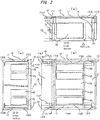
- FIG. 2 shows an example in the case where the ground bus of the board-type electrical equipment is arranged in the housing at the uppermost space or the lowermost space of the rear part of the electrical equipment main unit housing space, a ground bus is extended to the front side of the power cable housing space on the left side in the housing, and a ground wire attachment hole is provided in a ground bus extended to the front side thereof
- FIG. 2(a) is a cross-sectional plan view of the Y2-Y2 cross section in FIG. 2(b) as seen in the arrow direction
- FIG. 2(b) is a front view
- FIG. 2(c) is a longitudinal cross-sectional side view taken along the Z2-Z2 cross section in FIG. 2(b) in the arrow direction.
- an electrical equipment such as an enclosed switchboard, a control panel, a cubicle, as well as switchgear, as illustrated in FIG. 1
- an electrical equipment main unit housing space 10 and a power cable housing space 11 which are located on the right and left sides as seen in plan view are provided inside the housing 8
- an electrical equipment unit 83 (for example, a unit of a device such as a wiring circuit breaker or an electromagnetic switch) is housed in the electrical equipment main unit housing space 10
- a power cable for example, an external power supply lead-in cable, a power supply cable for load, etc.
- a ground bus 7 for grounding the electrical equipment main unit 83 is located behind the electrical equipment main unit housing space 10 and the power cable housing space 11, the ground bus 7, 7 of each of the electrical equipment arranged in rows, is connected by connecting the left and right extended ground bus 7LR, 7LR of the adjacent electrical equipment with the conductive connecting plate 7J.
- the structure is a right and left extending ground bus 7LR extending in the left and right as seen in a plan view and disposed in the housing 8, located on the opposite side to the electrical equipment housing space of the power cable housing space 11, extended forward and backward and disposed inside the housing 8 together with a front and rear extended ground bus 7LR extending in the housing 8 and connected to the left and right extended ground bus 7FR and having a ground wire attachment part 9 such as a ground wire attachment hole.
- the front-rear extended ground bus 7FR and the left-right extended ground bus 7LR as viewed from the front side, are provided by an upper side and/or a lower side, and are disposed at the same height as seen from the front side.
- the ground bus 7 is disposed at the rear of the housing 8, according to the ground bus 7 arranged at the rear part thereof, and is connected to the ground bus 7 of the electrical equipment next to the row board configuration.
- ground bus 7 arranged at the rear part of the electrical equipment main unit housing space 10 and the power cable housing space 11, along with a frame of the housing 8 (for example, an internal reinforcing frame of the housing 8, an electrical equipment unit housing frame, an exterior panel housing frame, etc. is attached to the inside of the exterior panel of the housing 8) extends to the front side of the power cable housing space 11 provided on the right side of the housing 8, and a ground wire attachment part 9 such as a ground wire attachment hole is provided on the extended ground bus 7.
- a frame of the housing 8 for example, an internal reinforcing frame of the housing 8, an electrical equipment unit housing frame, an exterior panel housing frame, etc. is attached to the inside of the exterior panel of the housing 8
- a ground wire attachment part 9 such as a ground wire attachment hole is provided on the extended ground bus 7.
- a ground wire 73 is connected to the ground bus 7 via the ground wire attachment part 9, the ground wire connection operation to be connected to the electrical equipment main unit 83 incorporated in the housing 8, wherein the power cable housing space 11 having a space margin, since it can be done easily, the height in the vertical direction of the electrical equipment main unit housing space 10, has not the necessary to reduce the amount of excessive raising space for the ground wire connection operation as in the past, and it is possible to increase the housing efficiency, obtains a space-saving and an economic efficiency of the electrical equipment unit which is the electrical equipment main unit 83.
- a ground wire 73 is connected to the ground bus 7 via the ground wire attachment part 9, the grounding wire connection operation to be connected to the electrical equipment main unit 83 incorporated in the housing 8 is performed before installing the power cable in the power cable housing space 11 or after assembling the power cable in the power cable housing space 11.
- FIG. 2 is an example of the structure in the case where the power cable housing space 16 is provided on the left side of the housing 13.
- the ground bus 12 is disposed at either the uppermost space or the lowermost space of the rear part of the housing 13, by the ground bus 12 arranged at the rear part thereof, and connected to the ground bus of the electrical equipment next to the row board configuration, the ground bus 12 disposed at the rear of the electric equipment main unit housing space 15 and the power cable housing space 16 is made to follow the frame of the housing 13, and the power cable housing part disposed on the left side of the housing 13 and extends to the front side of the space 16, and a ground wire attachment part 14 such as a ground wire attachment hole is provided on the extended ground bus 12.
- the ground wire connection operation can be performed without affecting the uppermost space 54 or the lowermost space 64 in this manner, compared to the past, in order to secure the space where the ground wire connecting work can be performed in the uppermost space 54 or the lowermost space 64, it is unnecessary to reduce the height of the electrical equipment main unit housing space 15 as a result of extra raising in the vertical direction, and it is possible to improve the housing efficiency of the electrical equipment main unit housing space 84, save space, and improve the economic efficiency.
- the housings 8, 8 constituting the row board are mechanically connected to each other, and the left and right extended ground bus 7LR, 7LR of the housings 8, 8 are electrically connected to each other by the conductive connection plate 7J, the laterally extended ground bus 12LR and 12LR of the respective housings 13 and 13 are also electrically connected to each other by a conductive connecting plate 12J, the ground wire connecting operation for connecting the ground wire 73 to the ground bus 7 via the grounding wire attachment part 9 to the electric equipment main unit 83 incorporated in the housing 8, this is done for each of the housings 8, 8 is performed for each of the housing, these are the same in the second and third embodiments to be described later.
- FIG. 3 is showing an example of a case where the ground bus of the board-type electrical equipment is disposed in the housing at either the uppermost space or the lowermost space of the rear part of the electrical equipment main unit housing space, in the case of the uppermost disposition, along the upper frame, in the case of the lowermost space disposition it is arranged along the lower frame, the ground bus is extended to the front side of the power cable housing space on the right side in the housing, and a ground wire attachment hole is provided in a ground bus extended to the front side thereof
- FIG. 3(a) is a cross-sectional plan view of the Y3-Y3 cross section in FIG. 3(b) as seen in the arrow direction
- FIG. 3(b) is a front view
- FIG. 3(c) is a longitudinal cross-sectional side view taken along the Z3-Z3 cross section in FIG. 3(b) in the arrow direction.
- FIG. 4 is showing an example of a case where the ground bus of the board-type electrical equipment is arranged in either the uppermost space or the lowermost space of the rear part of the electrical equipment main unit housing space in the housing, in the case of the uppermost housing, along the upper frame, is arranged along the lower frame in the case of the lowermost space, the ground bus is extended to the front side of the power cable housing space on the left side in the housing, and a ground wire attachment hole is provided in a ground bus extended to the front side thereof
- FIG. 3(a) is a cross-sectional plan view of the Y4-Y4 section in FIG. 3(b) as seen in the arrow direction
- FIG. 3(b) is a front view
- FIG. 3(c) is a longitudinal sectional side view of the section taken along the line Z4-Z4 in FIG. 3(b) as seen in the arrow direction.
- an electrical equipment main unit housing space 20 and a power cable housing space 21 which are positioned on the right and left sides as seen in plan view are provided inside the housing 18, an electrical equipment main unit 85 (for example, a unit of a device such as a wiring breaker, an electromagnetic switch) is housed in the electrical equipment main unit housing space 20, a power cable (for example, an external power supply lead-in cable, a power supply cable for load, etc.) connected to the electrical equipment main unit 85 is accommodated in the power cable housing space 21, a ground bus 17 for grounding the electrical equipment main unit 85 is located behind the electrical equipment main unit housing space 20 and the power cable housing space 21, a horizontally extending ground bus 17LR extending in the left and right as seen in plan view and disposed inside the housing 18, and is located on the side opposite to the electrical equipment main unit housing space 20 of the power cable housing space 21 and extends in the front-rear direction, and
- the front and rear extended ground bus 17FR and the left and right extended ground bus 17LR are disposed at different heights as viewed from the front side.
- the front and rear extended ground bus 17FR and the left and right extended ground bus 17LR are provided on either the upper side or the lower side as seen from the front side, in addition, as shown in the figures, in the front and rear extended ground bus 17FR and the left and right extended ground bus 17LR, in the case of the upper arrangement, the front and rear extended ground bus 17FR is positioned above the upper left and right extended ground bus 17LR when viewed from the front side, as shown in the figures, in the case of the lower side arrangement, the front and rear extended ground bus 17FR are positioned below the left and right extended ground bus 17LR as seen from the front side.
- the ground bus is extended from the rear part of the housing to the left and right front side, although a ground wire attachment hole is provided at the extension destination thereof, in the present embodiment, the ground bus is extended to either one of the upper side and the lower side of the housing, and ground wire attachment part such as a ground wire attachment hole is provided.
- the ground bus 17 is disposed at the rear of the housing 18, and is connected to the ground bus of the electrical equipment next to the row board configuration by the ground bus 17 arranged at the rear part.
- ground bus 17 disposed at the rear of the electrical equipment main unit housing space 20 and the power cable housing space 21 is made to follow the frame of either the upper part or the lower part of the housing 18, extends to the front side of the power cable housing space 21 provided on the right side of the housing 18, and a ground wire attachment part 19 such as a ground wire attachment hole is provided on the extended ground bus 17.
- FIG. 4 is an example of a structure in the case where the power cable housing space 26 is provided on the left side of the housing 23.
- the ground bus 22 is disposed at the rear of the housing 23,and connected to the ground bus of the electrical equipment next to the row board configuration by the ground bus 22 arranged at the rear part.
- ground bus 22 arranged at the rear of the electrical equipment main unit housing space 25 and the power cable housing space 26 is made to follow the frame of either the upper part or the lower part of the housing 23, extends to the front side of the power cable housing space 26 provided on the left side of the housing 23, and a grounding wire attachment part 24 such as a ground wire attachment hole is provided on the extended ground bus 22.
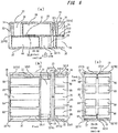
- FIG. 5 is a view showing an example of a case where a ground bus of a board type electrical equipment is disposed at either the uppermost space or the lowermost space at the center of the housing, the ground bus is extended from the ground bus arranged at the center along the left and right frames on the inner surface of the housing and in the front-rear direction of the housing
- FIG. 5(a) is a cross sectional plan view of the cross section taken along line Y5-Y5 in FIG. 5(b) as seen in the arrow direction
- FIG. 5(b) is a front view
- FIG. 5(c) is a longitudinal cross-sectional side view taken along the Z5-Z5 cross section in FIG. 5(b) in the arrow direction.
- FIG. 6 is a view showing an example of a case where the ground bus of the board-type electrical equipment is disposed at either the uppermost space or the lowermost space at the center of the housing, in the case of the uppermost disposition, is made to be along the upper frame, in the case of the disposition of the lowermost space, is made to follow the lower frame, the ground bus is extended in the front-rear direction of the housing,
- FIG. 6(a) is a cross-sectional plan view of the cross section taken along line Y6-Y6 in FIG. 6(b) as seen in the arrow direction
- FIG. 6(b) is a front view
- FIG. 6(c) is a longitudinal cross-sectional side view taken along the Z6-Z6 cross section in FIG. 6(b) in the arrow direction.
- an electrical equipment such as a closed switchboard, a control panel, a cubicle, or a switchgear, as illustrated in FIG. 5 , inside the housing 28, is provided by two pairs of electrical equipment main unit housing space 30 and power cable housing spaces 31 located on the right and left sides as seen in plan view, and having a structure wherein, the electrical equipment main unit is located in the electrical equipment main unit housing space 30, the electrical equipment in which the power cables connected to the electrical equipment main unit are located in each of the power cable housing spaces 31, the ground bus 27 for grounding each of the electrical equipment main unit 87 is located between the electrical equipment main unit housing space 30 and the power cable housing space 31 on the front side as seen in the plan view, and the electrical equipment main unit housing space 31 and the power cable housing space 30 on the rear side as seen in the plan view, as seen in the plan view, extended left and right, a left and right extended ground bus 27LR disposed inside the housing 28 is positioned on the opposite side to the front side of the electrical equipment main unit housing space 30 of the front side of
- the left and right extended ground bus 27LR, the first front and rear extended ground bus 27FR1 and the second front and rear extended ground bus 27FR2 are disposed at the same height as seen from the front side.
- the left and right extended ground bus 27LR, the first front and rear extended ground bus 27FR1, and the second front and rear extended ground bus 27FR2 are arranged at either the uppermost space or the lowermost space as seen from the front side.
- the ground bus 27 is arranged in the center of the housing 28.
- the ground bus 27 arranged at the center of the housing 28 connects to the ground bus of the electrical equipment next to the column structure.
- ground bus 27 arranged at the center of the housing 28 is extended along the left and right frames of the front or rear housing 28 of the housing 28 and extended to the power cable housing space 31. Further, a ground wire attachment part 29 such as a ground wire attachment hole is provided on the extended ground bus 27.
- FIG. 6 shows a structure in which the ground bus 32 is disposed at the center of the housing 33 and the ground bus 32 is extended on the top and bottom of the housing 33.
- the ground bus 32 is arranged at either the uppermost space or the lowermost space at the center of the housing 33, and the ground bus 32 arranged at the center thereof connects to the ground bus of the electrical equipment next to the column structure.
- the ground bus 32 arranged at the center is extended along the frame above or below the housing 33 on the front side or the rear side of the housing 33 and extended to the power cable housing space 36. Further, the ground wire attachment part 34 is provided on the extended ground bus 32.
- each embodiment can be appropriately combined, modified, or features omitted therein within the scope of the invention.
Landscapes
- Engineering & Computer Science (AREA)
- Power Engineering (AREA)
- Patch Boards (AREA)
Abstract
Description
- The present invention relates to an electrical equipment where, for example, a switchboard, called an electrical equipment main unit, is accommodated in a housing, particularly in the case where an electrical equipment, an electronic equipment or electric goods are accommodated in a metallic housing, in response to the possibility of electric shock when a person touches it, by connecting these equipment and facility to the ground via the housing, the difference between the potential and the ground is sufficiently reduced, and the arrangement of the ground bus connected with the ground intend to prevent electric shock.
-
FIG. 7(a) and FIG. 7(b) are a plan view and a front view showing an example of a conventional switchboard having a structure wherein, as seen from the plan view, the ground bus 1 is disposed at a position far from the front side of thehousing 2 and at a position far from the rear side together with, as seen from the front side, the lowermost space 61. - The arrangement of the ground bus 1 is considered to be able to connect the ground wire from the front side and the rear side. A ground
wire mounting hole 3 is provided in the ground bus 1, by connecting theground wire 71 of the electrical equipmentmain unit 81 to the groundwire mounting hole 3, the electrical equipmentmain unit 81 is grounded via theground wire 71. -
FIG. 8(a) and FIG. 8(b) are a plan view and a front view showing another example of the conventional switchboard having a structure wherein, as seen from the plan view, theground bus 4 is disposed in the position of the forefront side and the position on the rearmost side of thehousing 5 together with thelowermost space 62 as seen from the front side. - The arrangement of the
ground bus 4 is considered to be able to connect the ground wire from the front side and the rear side. A ground wire mounting hole 6 is provided in theground bus 4, and by connecting theground wire 72 of the electrical equipmentmain unit 82 to the ground wire mounting hole 6, the electrical equipmentmain unit 82 is grounded via thegrounding wire 72. - See Patent Document 1 as an example in which the ground bus is arranged at the position on the rearmost side of the housing.
-
- Patent Literature 1
-
JP 2012-249370 A - In a conventional switchboard shown in
FIG. 7(a) and FIG. 7(b) , as seen from the plan view, the ground bus 1 is arranged at a position far from the front side and at a position far from the rear side of thehousing 2 together with the lowermost space 61, as seen from the front side, although consideration is made so that the ground wire connection work can be performed from the front side and the rear side, in order to connect theground wire 71 to the groundwire mounting hole 3, a space for both hands of a person and a tool for attachment becomes necessary, and the lowermost space 61 must be secured to some extent in the vertical direction. Therefore, it is inevitable to reduce the electrical equipment mainunit housing space 40 in the vertical direction. - In the conventional switchboard shown in
FIG. 8(a) and FIG. 8(b) , as seen from the plan view, theground bus 4 is arranged at a position on the forefront side and the rearmost side of thehousing 5, together with thelowermost space 62 as seen from the front side, since the ground wire mounting hole 6 becomes also the foremost side and the rearmost side, even when thelowermost space 62 is minimized in the vertical direction, it is possible to perform the ground wire connection work. - However, if the
ground bus 4 is arranged at the position on the forefront side and the position on the rearmost side of thehousing 5, since theground bus 4 hinders the operation of connecting the external cable and the operation of connecting the foundation bolt, theground bus 4 must be arranged as shown inFIG. 7 , consequently, the problem inFIG. 7 , is that thelowermost space 62 has to be raised in the vertical direction in order to secure the space where the ground wire connection work can be performed, as a result, in order to secure a space where the ground wire can be connected, it is inevitable to reduce the electrical equipment mainunit housing space 45 in the vertical direction by a vertically raised extra space. - The present invention has been made in view of the above-described circumstances, and it is an object thereof to be able to dispose a ground bus without reducing the space for accommodating the electrical equipment main unit in the vertical direction.
- An electrical equipment according to the present invention is provided by an electrical equipment main unit housing space and an electric power cable housing space which are located on the right and left sides in a plan view in a housing, and, in the electrical equipment, an electrical equipment main unit is accommodated in the electrical equipment main unit housing space, a power cable connected to the electrical equipment main unit is accommodated in the power cable housing space, a ground bus for grounding the electrical equipment main unit is constructed by a left and right extended ground bus and a front and rear extended ground bus, and the left and right extended ground bus is located on a rear side position far from the electrical equipment main unit housing space in the housing and is disposed to be extended in a left and right direction as seen in a plan view, the front and rear extended ground bus is located on a side opposite to the electrical equipment main unit housing space of the power cable housing space, is disposed to be extended in a front and rear direction as seen in a plan view, is connected to the left and right extended ground bus, and has a ground wire attachment part.
- Further, according to the present invention, the electrical equipment having two pairs of electrical equipment main unit housing space and power cable housing spaces located on anteroposterior position as seen in a plan view in a housing, and, in the electrical equipment, an electrical equipment main unit is located in each of the electrical equipment main unit housing space, power cables connected to the electrical equipment main unit are located in each of the power cable housing spaces, a ground bus for grounding each of the electrical equipment main unit is constructed by a left and right extended ground bus, a first front and rear extended ground bus, and a second front and rear extended ground bus, further the left and right extended ground bus is located between the electrical equipment main unit housing space and the power cable housing space on the front side as seen in the plan view, and the electrical equipment main unit housing space and the power cable housing space on the rear side as seen in the plan view, the left and right extended ground bus is disposed to be extended left and right as seen in the plan view and disposed inside the housing, the first front and rear extended ground bus is positioned on the opposite side to the electrical equipment main unit housing space of the front side of the power cable housing space of the front side, is disposed to be extended in a front and rear direction as seen in a plan view, is connected to the left and right extended ground bus, and has a ground wire attachment part, and the second front and rear extended ground bus is positioned on the opposite side to the electrical equipment main unit housing space of the rear side of the power cable housing space of the rear side, is disposed to be extended in a front and rear direction as seen in a plan view, is connected to the left and right extended ground bus, and has another ground wire attachment part.
- According to the present invention, an electrical equipment is provided by an electrical equipment main unit housing space and an electric power cable housing space which are located on the right and left sides in a plan view in a housing, and, in the electrical equipment, an electrical equipment main unit is accommodated in the electrical equipment main unit housing space, a power cable connected to the electrical equipment main unit is accommodated in the power cable housing space, a ground bus for grounding the electrical equipment main unit is constructed by a left and right extended ground bus and a front and rear extended ground bus, and the left and right extended ground bus is located on a rear side position far from the electrical equipment main unit housing space in the housing and is disposed to be extended in a left and right direction as seen in a plan view, the front and rear extended ground bus is located on a side opposite to the electrical equipment main unit housing space of the power cable housing space, is disposed to be extended in a front and rear direction as seen in a plan view, is connected to the left and right extended ground bus, and has a ground wire attachment part, and further according to the present invention, the electrical equipment having two pairs of electrical equipment main unit housing space and power cable housing spaces located on anteroposterior position as seen in a plan view in a housing, and, in the electrical equipment, an electrical equipment main unit is located in each of the electrical equipment main unit housing space, power cables connected to the electrical equipment main unit are located in each of the power cable housing spaces, a ground bus for grounding each of the electrical equipment main unit is constructed by a left and right extended ground bus, a first front and rear extended ground bus, and a second front and rear extended ground bus, further the left and right extended ground bus is located between the electrical equipment main unit housing space and the power cable housing space on the front side as seen in the plan view, and the electrical equipment main unit housing space and the power cable housing space on the rear side as seen in the plan view, the left and right extended ground bus is disposed to be extended left and right as seen in the plan view and disposed inside the housing, the first front and rear extended ground bus is positioned on the opposite side to the electrical equipment main unit housing space of the front side of the power cable housing space of the front side, is disposed to be extended in a front and rear direction as seen in a plan view, is connected to the left and right extended ground bus, and has a ground wire attachment part, and the second front and rear extended ground bus is positioned on the opposite side to the electrical equipment main unit housing space of the rear side of the power cable housing space of the rear side, is disposed to be extended in a front and rear direction as seen in a plan view, is connected to the left and right extended ground bus, and has another ground wire attachment part.
- Thereby, it is possible to dispose the ground bus and to easily connect the ground wire to the ground bus without reducing the housing space of the electrical equipment main unit housing space in the vertical direction, in addition, without affecting the space in the vertical direction of the upper part, the lower part, and the upper part and the lower part of the electrical equipment main unit housing space in the housing.
-
-
FIG. 1 is a view showing a first embodiment of the present invention, and showing an example of the case where a ground bus of a board type electrical equipment is arranged at the rear part of the uppermost space or the lowermost space of the housing, the ground bus is extended to the front side of the power cable housing space on the right side in the housing, and a ground wire attachment hole is provided in the ground bus extended to the front side thereof,FIG. 1(a) is a cross sectional plan view of the Y-Y cross section inFIG. 1(b) as seen in the arrow direction,FIG. 1(b) is a front view, andFIG. 1(c) is a longitudinal sectional side view of the Z-Z section inFIG. 1(b) as seen in the arrow direction. -
FIG. 2 is a view showing a first embodiment of the present invention, and showing an example of the case where a ground bus of a board type electrical equipment is arranged at the rear part of the uppermost space or the lowermost space of the housing, the ground bus is extended to the front side of the power cable housing space on the left side in the housing, and a ground wire attachment hole is provided in the ground bus extended to the front side thereof,FIG. 2(a) is a cross-sectional plan view of the Y2-Y2 cross section inFIG. 2(b) as seen in the arrow direction,FIG. 2(b) is a front view, andFIG. 2(c) is a longitudinal cross-sectional side view taken along the Z2-Z2 cross section inFIG. 2(b) in the arrow direction. -
FIG. 3 is a view showing a second embodiment of the present invention, and showing an example of the case where a ground bus of a board type electrical equipment is arranged at the rear part of the uppermost space or the lowermost space of the housing, along the upper or lower frame in the housing, the ground bus is extended to the front side of the power cable housing space on the right side in the housing, and a ground wire attachment hole is provided in the ground bus extended to the front side thereof,FIG. 3(a) is a cross-sectional plan view of the Y3-Y3 cross section inFIG. 3(b) as seen in the arrow direction,FIG. 3(b) is a front view, andFIG. 3(c) is a vertical cross-sectional side view taken along the Z3-Z3 cross section inFIG. 3(b) in the arrow direction. -
FIG. 4 is a view showing a second embodiment of the present invention, and showing an example of the case where a ground bus of a board type electrical equipment is arranged at the rear part of the uppermost space or the lowermost space of the housing, along the upper frame when the ground bus is arranged at the top, and the lower frame when the ground bus is arranged at the bottom, a ground bus is extended to the front side of the power cable housing space on the left side in the housing, and a ground wire attachment hole is provided in the ground bus extended to the front side thereof,FIG. 4(a) is a cross sectional plan view of the Y4-Y4 section inFIG. 4(b) as seen in the arrow direction,FIG. 4(b) is a front view, andFIG. 4(c) is a longitudinal cross-sectional side view taken along the Z4-Z4 cross section inFIG. 4(b) in the arrow direction. -
FIG. 5 is a view showing a third embodiment of the present invention, and showing an example of the case where a ground bus of the board type electrical equipment is arranged at the uppermost space or the lowermost space of the center of the housing, the ground bus is extended from the ground bus arranged at the center along the left and right frames on the inner surface of the housing and in the front-rear direction of the housing,FIG. 5(a) is a cross sectional plan view of the cross section taken along line Y5-Y5 inFIG. 5(b) as seen in the arrow direction,FIG. 5(b) is a front view, andFIG. 5(c) is a longitudinal cross-sectional side view taken along the Z5-Z5 cross section inFIG. 5(b) in the arrow direction. -
FIG. 6 is a view showing a third embodiment of the present invention, and showing an example of the case where a ground bus of the board type electrical equipment is arranged at the uppermost space or the lowermost space of the center of the housing, along the upper frame when in the uppermost space housing, and in the lower frame when in the lowermost space housing, the ground bus is extended in the front and back direction of the housing,FIG. 6(a) is a cross-sectional plan view of the cross section taken along line Y6-Y6 inFIG. 6(b) as viewed in the direction of the arrow,FIG. 6(b) is a front view, andFIG. 6(c) is a longitudinal cross-sectional side view taken along the Z6-Z6 cross section inFIG. 6(b) in the arrow direction. -
FIG. 7 is a view showing an example in the case where the ground bus of the conventional switchboard is disposed at the bottom on the front side of the board and at the bottom on the rear side of the board,FIG. 7(a) is a cross-sectional plan view of the X-X cross section inFIG. 7(b) as seen in the arrow direction, andFIG. 7(b) is a front view. -
FIG. 8 is a view showing an example in the case where a ground bus of a conventional switchboard is disposed on the forefront side and the rearmost side of the lowermost space of the board,FIG. 8(a) is a cross sectional plan view of the XX-XX cross section inFIG. 8(b) as viewed in the arrow direction, andFIG. 8(b) is a front view. - Hereinafter, a first embodiment of the present invention will be described with reference to
FIG. 1 andFIG. 2 .FIG. 1 shows an example in the case where a ground bus of a board-type electrical equipment is disposed in either the uppermost space or the lowermost space of the rear part of the electric equipment main unit housing space in the housing, the ground bus is extended to the front side of the power cable housing space on the right side in the housing, and a ground wire attachment hole is provided in a ground bus extended to the front side thereof,FIG. 1(a) is a cross sectional plan view of the Y-Y section inFIG. 1(b) as seen in the arrow direction,FIG. 1(b) is a front view, andFIG. 1(c) is a longitudinal sectional side view of the Z-Z section inFIG. 1(b) as seen in the arrow direction. -
FIG. 2 shows an example in the case where the ground bus of the board-type electrical equipment is arranged in the housing at the uppermost space or the lowermost space of the rear part of the electrical equipment main unit housing space, a ground bus is extended to the front side of the power cable housing space on the left side in the housing, and a ground wire attachment hole is provided in a ground bus extended to the front side thereof,FIG. 2(a) is a cross-sectional plan view of the Y2-Y2 cross section inFIG. 2(b) as seen in the arrow direction,FIG. 2(b) is a front view, andFIG. 2(c) is a longitudinal cross-sectional side view taken along the Z2-Z2 cross section inFIG. 2(b) in the arrow direction. - In the first embodiment, for example, an electrical equipment such as an enclosed switchboard, a control panel, a cubicle, as well as switchgear, as illustrated in
FIG. 1 , an electrical equipment mainunit housing space 10 and a powercable housing space 11 which are located on the right and left sides as seen in plan view are provided inside thehousing 8, an electrical equipment unit 83 (for example, a unit of a device such as a wiring circuit breaker or an electromagnetic switch) is housed in the electrical equipment mainunit housing space 10, in an electrical equipment, a power cable (for example, an external power supply lead-in cable, a power supply cable for load, etc.) connected to the electrical equipmentmain unit 83 is housed in the powercable housing space 11, aground bus 7 for grounding the electrical equipmentmain unit 83 is located behind the electrical equipment mainunit housing space 10 and the powercable housing space 11, theground bus - The structure is a right and left extending ground bus 7LR extending in the left and right as seen in a plan view and disposed in the
housing 8, located on the opposite side to the electrical equipment housing space of the powercable housing space 11, extended forward and backward and disposed inside thehousing 8 together with a front and rear extended ground bus 7LR extending in thehousing 8 and connected to the left and right extended ground bus 7FR and having a groundwire attachment part 9 such as a ground wire attachment hole. - As shown in the figures, the front-rear extended ground bus 7FR and the left-right extended ground bus 7LR, as viewed from the front side, are provided by an upper side and/or a lower side, and are disposed at the same height as seen from the front side.
- To explain with a different point of view, the
ground bus 7 is disposed at the rear of thehousing 8, according to theground bus 7 arranged at the rear part thereof, and is connected to theground bus 7 of the electrical equipment next to the row board configuration. - Then, according to the
ground bus 7 arranged at the rear part of the electrical equipment mainunit housing space 10 and the powercable housing space 11, along with a frame of the housing 8 (for example, an internal reinforcing frame of thehousing 8, an electrical equipment unit housing frame, an exterior panel housing frame, etc. is attached to the inside of the exterior panel of the housing 8) extends to the front side of the powercable housing space 11 provided on the right side of thehousing 8, and a groundwire attachment part 9 such as a ground wire attachment hole is provided on the extendedground bus 7. - By providing the ground
wire attachment part 9 in the powercable housing space 11, a space for accommodating the uppermost space 53 (for example, a space for accommodating a board-to-board crossover cable, a terminal block, a power supply lead-in cable) or a lowermost space 63 (for example, a space for housing cables between boards, a terminal block), without having an adverse effect of increasing the extra space for the ground wire connection operation as in the past, aground wire 73 is connected to theground bus 7 via the groundwire attachment part 9, the ground wire connection operation to be connected to the electrical equipmentmain unit 83 incorporated in thehousing 8, wherein the powercable housing space 11 having a space margin, since it can be done easily, the height in the vertical direction of the electrical equipment mainunit housing space 10, has not the necessary to reduce the amount of excessive raising space for the ground wire connection operation as in the past, and it is possible to increase the housing efficiency, obtains a space-saving and an economic efficiency of the electrical equipment unit which is the electrical equipmentmain unit 83. - Further, a
ground wire 73 is connected to theground bus 7 via the groundwire attachment part 9, the grounding wire connection operation to be connected to the electrical equipmentmain unit 83 incorporated in thehousing 8 is performed before installing the power cable in the powercable housing space 11 or after assembling the power cable in the powercable housing space 11. -
FIG. 2 is an example of the structure in the case where the powercable housing space 16 is provided on the left side of thehousing 13. - The
ground bus 12 is disposed at either the uppermost space or the lowermost space of the rear part of thehousing 13, by theground bus 12 arranged at the rear part thereof, and connected to the ground bus of the electrical equipment next to the row board configuration, theground bus 12 disposed at the rear of the electric equipment mainunit housing space 15 and the powercable housing space 16 is made to follow the frame of thehousing 13, and the power cable housing part disposed on the left side of thehousing 13 and extends to the front side of thespace 16, and a groundwire attachment part 14 such as a ground wire attachment hole is provided on the extendedground bus 12. - By providing the ground
wire attachment part 14 in the powercable housing space 16, without affecting theuppermost space 54 or thelowermost space 64, it is possible to easily perform the operation of connecting the ground wire within the powercable housing space 11 having a margin in the space. - Since the ground wire connection operation can be performed without affecting the
uppermost space 54 or thelowermost space 64 in this manner, compared to the past, in order to secure the space where the ground wire connecting work can be performed in theuppermost space 54 or thelowermost space 64, it is unnecessary to reduce the height of the electrical equipment mainunit housing space 15 as a result of extra raising in the vertical direction, and it is possible to improve the housing efficiency of the electrical equipment mainunit housing space 84, save space, and improve the economic efficiency. - Further, As shown in the figures, the
housings housings respective housings plate 12J, the ground wire connecting operation for connecting theground wire 73 to theground bus 7 via the groundingwire attachment part 9 to the electric equipmentmain unit 83 incorporated in thehousing 8, this is done for each of thehousings - Hereinafter, a second embodiment will be described with reference to
FIG. 3 andFIG. 4 . -
FIG. 3 is showing an example of a case where the ground bus of the board-type electrical equipment is disposed in the housing at either the uppermost space or the lowermost space of the rear part of the electrical equipment main unit housing space, in the case of the uppermost disposition, along the upper frame, in the case of the lowermost space disposition it is arranged along the lower frame, the ground bus is extended to the front side of the power cable housing space on the right side in the housing, and a ground wire attachment hole is provided in a ground bus extended to the front side thereof,FIG. 3(a) is a cross-sectional plan view of the Y3-Y3 cross section inFIG. 3(b) as seen in the arrow direction,FIG. 3(b) is a front view, andFIG. 3(c) is a longitudinal cross-sectional side view taken along the Z3-Z3 cross section inFIG. 3(b) in the arrow direction. -
FIG. 4 is showing an example of a case where the ground bus of the board-type electrical equipment is arranged in either the uppermost space or the lowermost space of the rear part of the electrical equipment main unit housing space in the housing, in the case of the uppermost housing, along the upper frame, is arranged along the lower frame in the case of the lowermost space, the ground bus is extended to the front side of the power cable housing space on the left side in the housing, and a ground wire attachment hole is provided in a ground bus extended to the front side thereof,FIG. 3(a) is a cross-sectional plan view of the Y4-Y4 section inFIG. 3(b) as seen in the arrow direction,FIG. 3(b) is a front view, AndFIG. 3(c) is a longitudinal sectional side view of the section taken along the line Z4-Z4 inFIG. 3(b) as seen in the arrow direction. - In the second embodiment, for example, electrical equipment such as enclosed switchboards, control boards, cubicles, switch gears, as illustrated in
FIG. 3 , an electrical equipment mainunit housing space 20 and a powercable housing space 21 which are positioned on the right and left sides as seen in plan view are provided inside thehousing 18, an electrical equipment main unit 85 (for example, a unit of a device such as a wiring breaker, an electromagnetic switch) is housed in the electrical equipment mainunit housing space 20, a power cable (for example, an external power supply lead-in cable, a power supply cable for load, etc.) connected to the electrical equipmentmain unit 85 is accommodated in the powercable housing space 21, aground bus 17 for grounding the electrical equipmentmain unit 85 is located behind the electrical equipment mainunit housing space 20 and the powercable housing space 21, a horizontally extending ground bus 17LR extending in the left and right as seen in plan view and disposed inside thehousing 18, and is located on the side opposite to the electrical equipment mainunit housing space 20 of the powercable housing space 21 and extends in the front-rear direction, and a front and rear extended ground bus 17FR disposed inside thehousing 18 and connected to the left and right extended ground bus 17LR and which has a groundwire attachment part 19 such as a ground wire attachment hole. - As shown in the figures, the front and rear extended ground bus 17FR and the left and right extended ground bus 17LR are disposed at different heights as viewed from the front side.
- As shown in the figures, the front and rear extended ground bus 17FR and the left and right extended ground bus 17LR are provided on either the upper side or the lower side as seen from the front side, in addition, as shown in the figures, in the front and rear extended ground bus 17FR and the left and right extended ground bus 17LR, in the case of the upper arrangement, the front and rear extended ground bus 17FR is positioned above the upper left and right extended ground bus 17LR when viewed from the front side, as shown in the figures, in the case of the lower side arrangement, the front and rear extended ground bus 17FR are positioned below the left and right extended ground bus 17LR as seen from the front side.
- To explain with a different point of view, in the first embodiment, the ground bus is extended from the rear part of the housing to the left and right front side, although a ground wire attachment hole is provided at the extension destination thereof, in the present embodiment, the ground bus is extended to either one of the upper side and the lower side of the housing, and ground wire attachment part such as a ground wire attachment hole is provided.
- As shown in
FIG. 3 , theground bus 17 is disposed at the rear of thehousing 18, and is connected to the ground bus of the electrical equipment next to the row board configuration by theground bus 17 arranged at the rear part. - Then, the
ground bus 17 disposed at the rear of the electrical equipment mainunit housing space 20 and the powercable housing space 21 is made to follow the frame of either the upper part or the lower part of thehousing 18, extends to the front side of the powercable housing space 21 provided on the right side of thehousing 18, and a groundwire attachment part 19 such as a ground wire attachment hole is provided on theextended ground bus 17. - By providing the ground
wire attachment part 19 in the powercable housing space 21, without affecting theuppermost space 55 or thelowermost space 65, since it is possible to easily perform the grounding wire connecting operation within the powercable housing space 21 having a space margin, it is unnecessary to reduce the height of the electrical equipment mainunit housing space 20, and it is possible to improve the housing efficiency of the electrical equipmentmain unit 85, save space, and improve the economic efficiency. -
FIG. 4 is an example of a structure in the case where the powercable housing space 26 is provided on the left side of thehousing 23. - The
ground bus 22 is disposed at the rear of thehousing 23,and connected to the ground bus of the electrical equipment next to the row board configuration by theground bus 22 arranged at the rear part. - Then, the
ground bus 22 arranged at the rear of the electrical equipment mainunit housing space 25 and the powercable housing space 26 is made to follow the frame of either the upper part or the lower part of thehousing 23, extends to the front side of the powercable housing space 26 provided on the left side of thehousing 23, and a groundingwire attachment part 24 such as a ground wire attachment hole is provided on theextended ground bus 22. - By disposing the ground
wire attachment part 24 in the powercable housing space 26, without affecting theuppermost space 56 or thelowermost space 66, since it is possible to easily perform the grounding wire connecting operation within the powercable housing space 26 having a space margin, it is necessary to reduce the height of the electrical equipment mainunit housing space 25 as a result of excessively raising theuppermost space 56 or thelowermost space 66 in the vertical direction in order to secure a space for performing the ground wire connection operation, compared to the past, it is possible to improve the housing efficiency of the electrical equipmentmain unit 86, save space, and improve the economic efficiency. - Hereinafter, a third embodiment of the present invention will be described with reference to
FIG. 5 andFIG. 6 . -
FIG. 5 is a view showing an example of a case where a ground bus of a board type electrical equipment is disposed at either the uppermost space or the lowermost space at the center of the housing, the ground bus is extended from the ground bus arranged at the center along the left and right frames on the inner surface of the housing and in the front-rear direction of the housing,FIG. 5(a) is a cross sectional plan view of the cross section taken along line Y5-Y5 inFIG. 5(b) as seen in the arrow direction,FIG. 5(b) is a front view, andFIG. 5(c) is a longitudinal cross-sectional side view taken along the Z5-Z5 cross section inFIG. 5(b) in the arrow direction. -
FIG. 6 is a view showing an example of a case where the ground bus of the board-type electrical equipment is disposed at either the uppermost space or the lowermost space at the center of the housing, in the case of the uppermost disposition, is made to be along the upper frame, in the case of the disposition of the lowermost space, is made to follow the lower frame, the ground bus is extended in the front-rear direction of the housing,FIG. 6(a) is a cross-sectional plan view of the cross section taken along line Y6-Y6 inFIG. 6(b) as seen in the arrow direction,FIG. 6(b) is a front view,FIG. 6(c) is a longitudinal cross-sectional side view taken along the Z6-Z6 cross section inFIG. 6(b) in the arrow direction. - In the second embodiment, for example, an electrical equipment such as a closed switchboard, a control panel, a cubicle, or a switchgear, as illustrated in
FIG. 5 , inside the housing 28, is provided by two pairs of electrical equipment main unit housing space 30 and power cable housing spaces 31 located on the right and left sides as seen in plan view, and having a structure wherein, the electrical equipment main unit is located in the electrical equipment main unit housing space 30, the electrical equipment in which the power cables connected to the electrical equipment main unit are located in each of the power cable housing spaces 31, the ground bus 27 for grounding each of the electrical equipment main unit 87 is located between the electrical equipment main unit housing space 30 and the power cable housing space 31 on the front side as seen in the plan view, and the electrical equipment main unit housing space 31 and the power cable housing space 30 on the rear side as seen in the plan view, as seen in the plan view, extended left and right, a left and right extended ground bus 27LR disposed inside the housing 28 is positioned on the opposite side to the front side of the electrical equipment main unit housing space 30 of the front side of the power cable housing space 31, is disposed inside the housing 28, front side extended, together with the first front and rear extended ground bus 27FR1 connected to the left and right extended ground bus 27LR and having a ground wire attachment part 29, located on the opposite side of the rear side of the electrical equipment main unit housing space 30 of the rear side of the power cable housing space 31, extended in the front and rear side, and disposed inside the housing 28 together with a second front and rear extended ground bus 27FR2 connected to the left and right extended ground bus 27LR and having a ground wire attachment part 29. - As shown in the figures, the left and right extended ground bus 27LR, the first front and rear extended ground bus 27FR1 and the second front and rear extended ground bus 27FR2 are disposed at the same height as seen from the front side.
- As shown in the figures, the left and right extended ground bus 27LR, the first front and rear extended ground bus 27FR1, and the second front and rear extended ground bus 27FR2 are arranged at either the uppermost space or the lowermost space as seen from the front side.
- To explain with a different point of view, in the present embodiment, the
ground bus 27 is arranged in the center of thehousing 28. - As shown in
FIG. 5 , theground bus 27 arranged at the center of thehousing 28 connects to the ground bus of the electrical equipment next to the column structure. - Then, the
ground bus 27 arranged at the center of thehousing 28 is extended along the left and right frames of the front orrear housing 28 of thehousing 28 and extended to the powercable housing space 31.
Further, a groundwire attachment part 29 such as a ground wire attachment hole is provided on theextended ground bus 27. - By providing the ground
wire attachment part 29 in the powercable housing space 31, without affecting theuppermost space 57 or thelowermost space 67, in the powercable housing space 31 with a margin of space, since it can be done easily, compared to the past, it is unnecessary to reduce the height of the electrical equipment mainunit housing space 30 as a result of excessively raising theuppermost space 57 or thelowermost space 67 in the vertical direction in order to secure the space for performing the ground wire connection operation, and it is possible to increase the housing efficiency, space-saving and economic efficiency of the electrical equipmentmain unit 87. -
FIG. 6 shows a structure in which theground bus 32 is disposed at the center of thehousing 33 and theground bus 32 is extended on the top and bottom of thehousing 33. - As in
FIG. 5 , theground bus 32 is arranged at either the uppermost space or the lowermost space at the center of thehousing 33, and theground bus 32 arranged at the center thereof connects to the ground bus of the electrical equipment next to the column structure. - Then, the
ground bus 32 arranged at the center is extended along the frame above or below thehousing 33 on the front side or the rear side of thehousing 33 and extended to the powercable housing space 36.
Further, the groundwire attachment part 34 is provided on theextended ground bus 32. - By disposing the ground
wire attachment part 34 in the powercable housing space 36, without affecting theuppermost space 58 or thelowermost space 68, since it is possible to easily perform the ground wire attachment operation within the powercable housing space 36 having a space margin in the space, compared to the past, it is unnecessary to reduce the height of the electrical equipment mainunit housing space 35 as a result of excessively raising theuppermost space 58 or thelowermost space 68 in the vertical direction in order to secure the space for performing the ground wire connection operation, ant it is possible to improve the housing efficiency of the electrical equipmentmain unit 88, save space, and improve the economic efficiency. - In the present invention, each embodiment can be appropriately combined, modified, or features omitted therein within the scope of the invention.
- In the figures, the same reference numerals indicate the same or corresponding parts.
-
- 1, 4, 7, 12, 17, 22, 27, 32
- Ground bus
- 7LR, 12LR, 17LR
- Left and right extended ground bus
- 22LR, 27LR, 32LR
- Left and right extended ground bus
- 7FR, 12FR, 17FR, 22FR
- Front and rear extended ground bus
- 7J, 12J, 17J
- Conductive connection plate
- 22J, 27J, 32J
- Conductive connection plate
- 27FR1, 32FR1
- First front and rear extended ground bus Second front and rear extended ground bus
- 2, 5, 8, 13
- Housing
- 18, 23, 28, 33
- Housing
- 3, 6, 9, 14, 19
- Ground wire attachment part
- 24, 29, 34
- Ground wire attachment part
- 40, 45
- Electric equipment main unit housing space
- 11, 16, 21, 26, 31, 36
- Power cable housing space
- 53, 54, 55, 56, 57, 58
- Uppermost space
- 61, 62, 63, 64
- Lowermost space
- 65, 66, 67, 68
- Lowermost space
- 71, 72, 73
- Ground wire
- 81, 82, 83, 84
- Electrical equipment main unit
- 85, 86, 87, 88
- Electrical equipment main unit
Claims (12)
- An electrical equipment comprising an electrical equipment main unit housing space and an electric power cable housing space which are located on the right and left sides in a plan view in a housing, wherein;- an electrical equipment main unit is accommodated in the electrical equipment main unit housing space,- a power cable connected to the electrical equipment main unit is accommodated in the power cable housing space,- a ground bus for grounding the electrical equipment main unit is constructed by a left and right extended ground bus and a front and rear extended ground bus,- wherein, the left and right extended ground bus is located on a rear side position far from the electrical equipment main unit housing space in the housing and is disposed to be extended in a left and right direction as seen in a plan view,- wherein, the front and rear extended ground bus is located on a side opposite to the electrical equipment main unit housing space of the power cable housing space, is disposed to be extended in a front and rear direction as seen in a plan view, is connected to the left and right extended ground bus, and has a ground wire attachment part.
- The electrical equipment according to claim 1,
wherein the front and rear extended ground bus and the left and right extended ground bus are provided on at least one of an upper side and a lower side of the interior of the housing as seen from the front side. - The electrical equipment according to claim 1 or 2,
wherein the front and rear extended ground bus and the left and right extended ground bus are arranged at the same height as seen from the front side. - The electrical equipment according to claim 1 or 2,
wherein the front and rear extended ground bus and the left and right extending ground buses are arranged at different heights as seen from the front side. - The electrical equipment according to claim 2,
wherein among a pair of the front and rear extended ground bus and the left and right extended ground bus, the front and rear extended ground bus on an upper side, as seen from the front side, is positioned above the left and right extended ground bus on an upper side, the lower front and rear extended ground bus on a lower side, as seen from the front side, is positioned below the left and right extended ground bus on a lower side. - The electrical equipment according to any one of claims 1 to 5,
wherein in the case of a row board configuration in which a plurality of the electrical equipment is installed adjacently on the left and right in plan view, the ground bus of each of the electrical equipment are connected to each other. - An electrical equipment comprising two pairs of electrical equipment main unit housing space and power cable housing spaces located on anteroposterior position as seen in a plan view in a housing, wherein;
an electrical equipment main unit is located in each of the electrical equipment main unit housing space,
power cables connected to the electrical equipment main unit are located in each of the power cable housing spaces,
a ground bus for grounding each of the electrical equipment main unit is constructed by a left and right extended ground bus, a first front and rear extended ground bus, and a second front and rear extended ground bus, wherein, the left and right extended ground bus is located between the electrical equipment main unit housing space and the power cable housing space on the front side as seen in the plan view, and the electrical equipment main unit housing space and the power cable housing space on the rear side as seen in the plan view,
the left and right extended ground bus is disposed to be extended left and right as seen in the plan view and disposed inside the housing, wherein, the first front and rear extended ground bus is positioned on the opposite side to the electrical equipment main unit housing space of the front side of the power cable housing space of the front side, is disposed to be extended in a front and rear direction as seen in a plan view, is connected to the left and right extended ground bus, and has a ground wire attachment part,
wherein, the second front and rear extended ground bus is positioned on the opposite side to the electrical equipment main unit housing space of the rear side of the power cable housing space of the rear side, is disposed to be extended in a front and rear direction as seen in a plan view, is connected to the left and right extended ground bus, and has another ground wire attachment part. - The electrical equipment according to claim 7,
wherein the left and right extended ground bus, the first front and rear extended ground bus, and the second front and rear extended ground bus are provided on at least one of an upper side and a lower side of the inside of the housing as seen from the front side. - The electrical equipment according to claim 7 or 8,
wherein the left and right extended ground bus, the first front and rear extended ground bus, and the second front and rear extended ground bus are disposed at the same height as seen from the front side. - The electrical equipment according to claim 7 or 8,
wherein the first front and rear extended ground bus and the left and right extended ground bus are arranged at different heights as seen from the front side, and the second front and rear extended ground bus and the left and right extended ground bus are disposed at different heights as seen from the front side. - The electrical equipment according to claim 8,
wherein in a pair of the first front and rear extended ground bus, the second front and rear extended ground bus, and the left and right extended ground bus, the first front-rear extended ground bus on an upper side and the second front and rear extended ground bus on an upper side, as seen from the front side, are positioned above the left and right extending ground bus on an upper side, and the first front and rear extended ground bus on a lower side and the second front and rear extended ground bus on a lower side are positioned below the left and right extended ground bus on a lower side. - The electrical equipment according to any one of claims 7 to 11,
wherein in the case of a row board configuration in which a plurality of the electrical equipment is installed adjacently on the left and right in a plan view, the ground buses of the respective electrical equipment are connected to each other.
Applications Claiming Priority (2)
| Application Number | Priority Date | Filing Date | Title |
|---|---|---|---|
| JP2015050221 | 2015-03-13 | ||
| PCT/JP2015/084596 WO2016147502A1 (en) | 2015-03-13 | 2015-12-10 | Electric apparatus |
Publications (3)
| Publication Number | Publication Date |
|---|---|
| EP3270477A1 true EP3270477A1 (en) | 2018-01-17 |
| EP3270477A4 EP3270477A4 (en) | 2019-02-13 |
| EP3270477B1 EP3270477B1 (en) | 2021-10-13 |
Family
ID=56919779
Family Applications (1)
| Application Number | Title | Priority Date | Filing Date |
|---|---|---|---|
| EP15885594.0A Active EP3270477B1 (en) | 2015-03-13 | 2015-12-10 | Electric apparatus |
Country Status (3)
| Country | Link |
|---|---|
| EP (1) | EP3270477B1 (en) |
| JP (1) | JP5989287B1 (en) |
| WO (1) | WO2016147502A1 (en) |
Cited By (1)
| Publication number | Priority date | Publication date | Assignee | Title |
|---|---|---|---|---|
| CN109301709A (en) * | 2018-10-29 | 2019-02-01 | 海安美物菲斯物联网科技有限公司 | A kind of townhouse formula low-voltage cabinet that can accurately dock |
Families Citing this family (1)
| Publication number | Priority date | Publication date | Assignee | Title |
|---|---|---|---|---|
| CN112928633B (en) * | 2021-03-18 | 2022-10-21 | 安徽长龙电气集团有限公司 | Power distribution cabinet |
Family Cites Families (6)
| Publication number | Priority date | Publication date | Assignee | Title |
|---|---|---|---|---|
| JPS565451Y2 (en) * | 1976-03-22 | 1981-02-05 | ||
| JP2002252906A (en) * | 2001-02-23 | 2002-09-06 | Fuji Electric Co Ltd | Mounting structure of the grounding bus of the row type switchboard |
| JP4504341B2 (en) * | 2006-10-16 | 2010-07-14 | 日本電信電話株式会社 | Current distribution device |
| JP5081853B2 (en) * | 2009-03-02 | 2012-11-28 | 株式会社日立製作所 | switchboard |
| JP2012249370A (en) * | 2011-05-26 | 2012-12-13 | Mitsubishi Electric Corp | Switchgear |
| CN202260151U (en) * | 2011-09-30 | 2012-05-30 | 无锡中科电气设备有限公司 | Communication lead shield passage of low-voltage complete equipment |
-
2015
- 2015-12-10 WO PCT/JP2015/084596 patent/WO2016147502A1/en not_active Ceased
- 2015-12-10 JP JP2016529481A patent/JP5989287B1/en active Active
- 2015-12-10 EP EP15885594.0A patent/EP3270477B1/en active Active
Cited By (1)
| Publication number | Priority date | Publication date | Assignee | Title |
|---|---|---|---|---|
| CN109301709A (en) * | 2018-10-29 | 2019-02-01 | 海安美物菲斯物联网科技有限公司 | A kind of townhouse formula low-voltage cabinet that can accurately dock |
Also Published As
| Publication number | Publication date |
|---|---|
| JPWO2016147502A1 (en) | 2017-04-27 |
| EP3270477A4 (en) | 2019-02-13 |
| JP5989287B1 (en) | 2016-09-07 |
| EP3270477B1 (en) | 2021-10-13 |
| WO2016147502A1 (en) | 2016-09-22 |
Similar Documents
| Publication | Publication Date | Title |
|---|---|---|
| KR101337012B1 (en) | Switchgear | |
| US6301095B1 (en) | System and method of distributing power to a plurality of electronic modules housed within an electronics cabinet | |
| US5574251A (en) | Electrical and electronic cabinet systems | |
| TWI485946B (en) | Power storage device | |
| EP3243705B1 (en) | Utility vehicle power distribution module | |
| EP2192006B1 (en) | Junction box for a vehicle | |
| US20120228929A1 (en) | Modular power distributor | |
| US7160118B2 (en) | Electric junction box | |
| CN112352362A (en) | Terminal block and conductive path | |
| CN104685741B (en) | Electric circuit connection container | |
| WO2018159352A1 (en) | Connection module | |
| EP3270477B1 (en) | Electric apparatus | |
| US9615470B2 (en) | Wiring combiner box | |
| DE112017006041B4 (en) | power converter | |
| JP4979481B2 (en) | Bar holder for distribution board | |
| JP5081853B2 (en) | switchboard | |
| JP4958282B2 (en) | Breaker unit | |
| KR101103276B1 (en) | Junction box | |
| JP6562755B2 (en) | Switchgear | |
| JP5971924B2 (en) | Switchgear | |
| JP2009177969A (en) | Distribution board | |
| JP2020126806A (en) | Wiring structure | |
| JP2003324809A (en) | switchboard | |
| JP7382891B2 (en) | DC switchboard | |
| KR102884732B1 (en) | Distribution board |
Legal Events
| Date | Code | Title | Description |
|---|---|---|---|
| STAA | Information on the status of an ep patent application or granted ep patent |
Free format text: STATUS: THE INTERNATIONAL PUBLICATION HAS BEEN MADE |
|
| PUAI | Public reference made under article 153(3) epc to a published international application that has entered the european phase |
Free format text: ORIGINAL CODE: 0009012 |
|
| STAA | Information on the status of an ep patent application or granted ep patent |
Free format text: STATUS: REQUEST FOR EXAMINATION WAS MADE |
|
| 17P | Request for examination filed |
Effective date: 20170913 |
|
| AK | Designated contracting states |
Kind code of ref document: A1 Designated state(s): AL AT BE BG CH CY CZ DE DK EE ES FI FR GB GR HR HU IE IS IT LI LT LU LV MC MK MT NL NO PL PT RO RS SE SI SK SM TR |
|
| AX | Request for extension of the european patent |
Extension state: BA ME |
|
| DAV | Request for validation of the european patent (deleted) | ||
| DAX | Request for extension of the european patent (deleted) | ||
| A4 | Supplementary search report drawn up and despatched |
Effective date: 20190115 |
|
| RIC1 | Information provided on ipc code assigned before grant |
Ipc: H02B 1/32 20060101ALN20190109BHEP Ipc: H02B 1/16 20060101AFI20190109BHEP Ipc: H02B 1/20 20060101ALN20190109BHEP |
|
| STAA | Information on the status of an ep patent application or granted ep patent |
Free format text: STATUS: EXAMINATION IS IN PROGRESS |
|
| 17Q | First examination report despatched |
Effective date: 20200207 |
|
| GRAP | Despatch of communication of intention to grant a patent |
Free format text: ORIGINAL CODE: EPIDOSNIGR1 |
|
| STAA | Information on the status of an ep patent application or granted ep patent |
Free format text: STATUS: GRANT OF PATENT IS INTENDED |
|
| INTG | Intention to grant announced |
Effective date: 20201030 |
|
| GRAJ | Information related to disapproval of communication of intention to grant by the applicant or resumption of examination proceedings by the epo deleted |
Free format text: ORIGINAL CODE: EPIDOSDIGR1 |
|
| STAA | Information on the status of an ep patent application or granted ep patent |
Free format text: STATUS: EXAMINATION IS IN PROGRESS |
|
| INTC | Intention to grant announced (deleted) | ||
| GRAP | Despatch of communication of intention to grant a patent |
Free format text: ORIGINAL CODE: EPIDOSNIGR1 |
|
| STAA | Information on the status of an ep patent application or granted ep patent |
Free format text: STATUS: GRANT OF PATENT IS INTENDED |
|
| INTG | Intention to grant announced |
Effective date: 20210428 |
|
| GRAS | Grant fee paid |
Free format text: ORIGINAL CODE: EPIDOSNIGR3 |
|
| GRAA | (expected) grant |
Free format text: ORIGINAL CODE: 0009210 |
|
| STAA | Information on the status of an ep patent application or granted ep patent |
Free format text: STATUS: THE PATENT HAS BEEN GRANTED |
|
| AK | Designated contracting states |
Kind code of ref document: B1 Designated state(s): AL AT BE BG CH CY CZ DE DK EE ES FI FR GB GR HR HU IE IS IT LI LT LU LV MC MK MT NL NO PL PT RO RS SE SI SK SM TR |
|
| REG | Reference to a national code |
Ref country code: GB Ref legal event code: FG4D |
|
| REG | Reference to a national code |
Ref country code: CH Ref legal event code: EP |
|
| REG | Reference to a national code |
Ref country code: DE Ref legal event code: R096 Ref document number: 602015074181 Country of ref document: DE |
|
| REG | Reference to a national code |
Ref country code: IE Ref legal event code: FG4D |
|
| REG | Reference to a national code |
Ref country code: AT Ref legal event code: REF Ref document number: 1438866 Country of ref document: AT Kind code of ref document: T Effective date: 20211115 |
|
| REG | Reference to a national code |
Ref country code: LT Ref legal event code: MG9D |
|
| REG | Reference to a national code |
Ref country code: NL Ref legal event code: MP Effective date: 20211013 |
|
| REG | Reference to a national code |
Ref country code: AT Ref legal event code: MK05 Ref document number: 1438866 Country of ref document: AT Kind code of ref document: T Effective date: 20211013 |
|
| PG25 | Lapsed in a contracting state [announced via postgrant information from national office to epo] |
Ref country code: RS Free format text: LAPSE BECAUSE OF FAILURE TO SUBMIT A TRANSLATION OF THE DESCRIPTION OR TO PAY THE FEE WITHIN THE PRESCRIBED TIME-LIMIT Effective date: 20211013 Ref country code: LT Free format text: LAPSE BECAUSE OF FAILURE TO SUBMIT A TRANSLATION OF THE DESCRIPTION OR TO PAY THE FEE WITHIN THE PRESCRIBED TIME-LIMIT Effective date: 20211013 Ref country code: FI Free format text: LAPSE BECAUSE OF FAILURE TO SUBMIT A TRANSLATION OF THE DESCRIPTION OR TO PAY THE FEE WITHIN THE PRESCRIBED TIME-LIMIT Effective date: 20211013 Ref country code: BG Free format text: LAPSE BECAUSE OF FAILURE TO SUBMIT A TRANSLATION OF THE DESCRIPTION OR TO PAY THE FEE WITHIN THE PRESCRIBED TIME-LIMIT Effective date: 20220113 Ref country code: AT Free format text: LAPSE BECAUSE OF FAILURE TO SUBMIT A TRANSLATION OF THE DESCRIPTION OR TO PAY THE FEE WITHIN THE PRESCRIBED TIME-LIMIT Effective date: 20211013 |
|
| PG25 | Lapsed in a contracting state [announced via postgrant information from national office to epo] |
Ref country code: IS Free format text: LAPSE BECAUSE OF FAILURE TO SUBMIT A TRANSLATION OF THE DESCRIPTION OR TO PAY THE FEE WITHIN THE PRESCRIBED TIME-LIMIT Effective date: 20220213 Ref country code: SE Free format text: LAPSE BECAUSE OF FAILURE TO SUBMIT A TRANSLATION OF THE DESCRIPTION OR TO PAY THE FEE WITHIN THE PRESCRIBED TIME-LIMIT Effective date: 20211013 Ref country code: PT Free format text: LAPSE BECAUSE OF FAILURE TO SUBMIT A TRANSLATION OF THE DESCRIPTION OR TO PAY THE FEE WITHIN THE PRESCRIBED TIME-LIMIT Effective date: 20220214 Ref country code: PL Free format text: LAPSE BECAUSE OF FAILURE TO SUBMIT A TRANSLATION OF THE DESCRIPTION OR TO PAY THE FEE WITHIN THE PRESCRIBED TIME-LIMIT Effective date: 20211013 Ref country code: NO Free format text: LAPSE BECAUSE OF FAILURE TO SUBMIT A TRANSLATION OF THE DESCRIPTION OR TO PAY THE FEE WITHIN THE PRESCRIBED TIME-LIMIT Effective date: 20220113 Ref country code: NL Free format text: LAPSE BECAUSE OF FAILURE TO SUBMIT A TRANSLATION OF THE DESCRIPTION OR TO PAY THE FEE WITHIN THE PRESCRIBED TIME-LIMIT Effective date: 20211013 Ref country code: LV Free format text: LAPSE BECAUSE OF FAILURE TO SUBMIT A TRANSLATION OF THE DESCRIPTION OR TO PAY THE FEE WITHIN THE PRESCRIBED TIME-LIMIT Effective date: 20211013 Ref country code: HR Free format text: LAPSE BECAUSE OF FAILURE TO SUBMIT A TRANSLATION OF THE DESCRIPTION OR TO PAY THE FEE WITHIN THE PRESCRIBED TIME-LIMIT Effective date: 20211013 Ref country code: GR Free format text: LAPSE BECAUSE OF FAILURE TO SUBMIT A TRANSLATION OF THE DESCRIPTION OR TO PAY THE FEE WITHIN THE PRESCRIBED TIME-LIMIT Effective date: 20220114 Ref country code: ES Free format text: LAPSE BECAUSE OF FAILURE TO SUBMIT A TRANSLATION OF THE DESCRIPTION OR TO PAY THE FEE WITHIN THE PRESCRIBED TIME-LIMIT Effective date: 20211013 |
|
| REG | Reference to a national code |
Ref country code: DE Ref legal event code: R097 Ref document number: 602015074181 Country of ref document: DE |
|
| PG25 | Lapsed in a contracting state [announced via postgrant information from national office to epo] |
Ref country code: SM Free format text: LAPSE BECAUSE OF FAILURE TO SUBMIT A TRANSLATION OF THE DESCRIPTION OR TO PAY THE FEE WITHIN THE PRESCRIBED TIME-LIMIT Effective date: 20211013 Ref country code: SK Free format text: LAPSE BECAUSE OF FAILURE TO SUBMIT A TRANSLATION OF THE DESCRIPTION OR TO PAY THE FEE WITHIN THE PRESCRIBED TIME-LIMIT Effective date: 20211013 Ref country code: RO Free format text: LAPSE BECAUSE OF FAILURE TO SUBMIT A TRANSLATION OF THE DESCRIPTION OR TO PAY THE FEE WITHIN THE PRESCRIBED TIME-LIMIT Effective date: 20211013 Ref country code: MC Free format text: LAPSE BECAUSE OF FAILURE TO SUBMIT A TRANSLATION OF THE DESCRIPTION OR TO PAY THE FEE WITHIN THE PRESCRIBED TIME-LIMIT Effective date: 20211013 Ref country code: EE Free format text: LAPSE BECAUSE OF FAILURE TO SUBMIT A TRANSLATION OF THE DESCRIPTION OR TO PAY THE FEE WITHIN THE PRESCRIBED TIME-LIMIT Effective date: 20211013 Ref country code: DK Free format text: LAPSE BECAUSE OF FAILURE TO SUBMIT A TRANSLATION OF THE DESCRIPTION OR TO PAY THE FEE WITHIN THE PRESCRIBED TIME-LIMIT Effective date: 20211013 Ref country code: CZ Free format text: LAPSE BECAUSE OF FAILURE TO SUBMIT A TRANSLATION OF THE DESCRIPTION OR TO PAY THE FEE WITHIN THE PRESCRIBED TIME-LIMIT Effective date: 20211013 |
|
| REG | Reference to a national code |
Ref country code: CH Ref legal event code: PL |
|
| PLBE | No opposition filed within time limit |
Free format text: ORIGINAL CODE: 0009261 |
|
| STAA | Information on the status of an ep patent application or granted ep patent |
Free format text: STATUS: NO OPPOSITION FILED WITHIN TIME LIMIT |
|
| 26N | No opposition filed |
Effective date: 20220714 |
|
| REG | Reference to a national code |
Ref country code: BE Ref legal event code: MM Effective date: 20211231 |
|
| GBPC | Gb: european patent ceased through non-payment of renewal fee |
Effective date: 20220113 |
|
| PG25 | Lapsed in a contracting state [announced via postgrant information from national office to epo] |
Ref country code: LU Free format text: LAPSE BECAUSE OF NON-PAYMENT OF DUE FEES Effective date: 20211210 Ref country code: IE Free format text: LAPSE BECAUSE OF NON-PAYMENT OF DUE FEES Effective date: 20211210 Ref country code: GB Free format text: LAPSE BECAUSE OF NON-PAYMENT OF DUE FEES Effective date: 20220113 Ref country code: AL Free format text: LAPSE BECAUSE OF FAILURE TO SUBMIT A TRANSLATION OF THE DESCRIPTION OR TO PAY THE FEE WITHIN THE PRESCRIBED TIME-LIMIT Effective date: 20211013 |
|
| PG25 | Lapsed in a contracting state [announced via postgrant information from national office to epo] |
Ref country code: SI Free format text: LAPSE BECAUSE OF FAILURE TO SUBMIT A TRANSLATION OF THE DESCRIPTION OR TO PAY THE FEE WITHIN THE PRESCRIBED TIME-LIMIT Effective date: 20211013 Ref country code: FR Free format text: LAPSE BECAUSE OF NON-PAYMENT OF DUE FEES Effective date: 20211213 Ref country code: BE Free format text: LAPSE BECAUSE OF NON-PAYMENT OF DUE FEES Effective date: 20211231 |
|
| PG25 | Lapsed in a contracting state [announced via postgrant information from national office to epo] |
Ref country code: LI Free format text: LAPSE BECAUSE OF NON-PAYMENT OF DUE FEES Effective date: 20211231 Ref country code: CH Free format text: LAPSE BECAUSE OF NON-PAYMENT OF DUE FEES Effective date: 20211231 |
|
| PG25 | Lapsed in a contracting state [announced via postgrant information from national office to epo] |
Ref country code: IT Free format text: LAPSE BECAUSE OF FAILURE TO SUBMIT A TRANSLATION OF THE DESCRIPTION OR TO PAY THE FEE WITHIN THE PRESCRIBED TIME-LIMIT Effective date: 20211013 Ref country code: HU Free format text: LAPSE BECAUSE OF FAILURE TO SUBMIT A TRANSLATION OF THE DESCRIPTION OR TO PAY THE FEE WITHIN THE PRESCRIBED TIME-LIMIT; INVALID AB INITIO Effective date: 20151210 |
|
| P01 | Opt-out of the competence of the unified patent court (upc) registered |
Effective date: 20230512 |
|
| PG25 | Lapsed in a contracting state [announced via postgrant information from national office to epo] |
Ref country code: CY Free format text: LAPSE BECAUSE OF FAILURE TO SUBMIT A TRANSLATION OF THE DESCRIPTION OR TO PAY THE FEE WITHIN THE PRESCRIBED TIME-LIMIT Effective date: 20211013 |
|
| PG25 | Lapsed in a contracting state [announced via postgrant information from national office to epo] |
Ref country code: MK Free format text: LAPSE BECAUSE OF FAILURE TO SUBMIT A TRANSLATION OF THE DESCRIPTION OR TO PAY THE FEE WITHIN THE PRESCRIBED TIME-LIMIT Effective date: 20211013 |
|
| PG25 | Lapsed in a contracting state [announced via postgrant information from national office to epo] |
Ref country code: TR Free format text: LAPSE BECAUSE OF FAILURE TO SUBMIT A TRANSLATION OF THE DESCRIPTION OR TO PAY THE FEE WITHIN THE PRESCRIBED TIME-LIMIT Effective date: 20211013 |
|
| PG25 | Lapsed in a contracting state [announced via postgrant information from national office to epo] |
Ref country code: MT Free format text: LAPSE BECAUSE OF FAILURE TO SUBMIT A TRANSLATION OF THE DESCRIPTION OR TO PAY THE FEE WITHIN THE PRESCRIBED TIME-LIMIT Effective date: 20211013 |
|
| REG | Reference to a national code |
Ref country code: DE Ref legal event code: R084 Ref document number: 602015074181 Country of ref document: DE |
|
| PGFP | Annual fee paid to national office [announced via postgrant information from national office to epo] |
Ref country code: DE Payment date: 20251028 Year of fee payment: 11 |