EP3270462A2 - Antenne de diversité à ailettes - Google Patents
Antenne de diversité à ailettes Download PDFInfo
- Publication number
- EP3270462A2 EP3270462A2 EP17199008.8A EP17199008A EP3270462A2 EP 3270462 A2 EP3270462 A2 EP 3270462A2 EP 17199008 A EP17199008 A EP 17199008A EP 3270462 A2 EP3270462 A2 EP 3270462A2
- Authority
- EP
- European Patent Office
- Prior art keywords
- antenna
- converter
- optical
- gain
- diversity
- Prior art date
- Legal status (The legal status is an assumption and is not a legal conclusion. Google has not performed a legal analysis and makes no representation as to the accuracy of the status listed.)
- Granted
Links
- 230000003287 optical effect Effects 0.000 claims abstract description 92
- 230000001066 destructive effect Effects 0.000 claims abstract description 25
- 238000000034 method Methods 0.000 claims description 59
- 238000006243 chemical reaction Methods 0.000 claims description 15
- 238000004891 communication Methods 0.000 claims description 10
- 238000005388 cross polarization Methods 0.000 abstract description 17
- 239000000758 substrate Substances 0.000 description 25
- 239000000835 fiber Substances 0.000 description 16
- 238000010586 diagram Methods 0.000 description 11
- 230000002829 reductive effect Effects 0.000 description 11
- 238000004590 computer program Methods 0.000 description 9
- 239000000463 material Substances 0.000 description 9
- 230000010287 polarization Effects 0.000 description 9
- 230000006870 function Effects 0.000 description 8
- 230000000737 periodic effect Effects 0.000 description 6
- 230000008901 benefit Effects 0.000 description 5
- XLYOFNOQVPJJNP-UHFFFAOYSA-N water Substances O XLYOFNOQVPJJNP-UHFFFAOYSA-N 0.000 description 5
- 230000005540 biological transmission Effects 0.000 description 4
- 230000000694 effects Effects 0.000 description 4
- 238000004088 simulation Methods 0.000 description 4
- 241000251730 Chondrichthyes Species 0.000 description 3
- 239000004593 Epoxy Substances 0.000 description 3
- 238000004458 analytical method Methods 0.000 description 3
- 239000004020 conductor Substances 0.000 description 3
- 238000010276 construction Methods 0.000 description 3
- 238000006073 displacement reaction Methods 0.000 description 3
- 230000000670 limiting effect Effects 0.000 description 3
- 230000004044 response Effects 0.000 description 3
- 230000009286 beneficial effect Effects 0.000 description 2
- 238000000576 coating method Methods 0.000 description 2
- 230000003111 delayed effect Effects 0.000 description 2
- 230000009977 dual effect Effects 0.000 description 2
- 239000011152 fibreglass Substances 0.000 description 2
- 238000001914 filtration Methods 0.000 description 2
- 230000008569 process Effects 0.000 description 2
- 230000009467 reduction Effects 0.000 description 2
- 238000000926 separation method Methods 0.000 description 2
- 238000001228 spectrum Methods 0.000 description 2
- RYGMFSIKBFXOCR-UHFFFAOYSA-N Copper Chemical compound [Cu] RYGMFSIKBFXOCR-UHFFFAOYSA-N 0.000 description 1
- 101000702606 Homo sapiens Structure-specific endonuclease subunit SLX4 Proteins 0.000 description 1
- 102100031003 Structure-specific endonuclease subunit SLX4 Human genes 0.000 description 1
- 230000002411 adverse Effects 0.000 description 1
- 238000003491 array Methods 0.000 description 1
- 230000002238 attenuated effect Effects 0.000 description 1
- 238000010009 beating Methods 0.000 description 1
- 238000005452 bending Methods 0.000 description 1
- 238000004364 calculation method Methods 0.000 description 1
- 239000000969 carrier Substances 0.000 description 1
- 238000004140 cleaning Methods 0.000 description 1
- 239000011248 coating agent Substances 0.000 description 1
- 239000003086 colorant Substances 0.000 description 1
- 229910052802 copper Inorganic materials 0.000 description 1
- 239000010949 copper Substances 0.000 description 1
- 230000007797 corrosion Effects 0.000 description 1
- 238000005260 corrosion Methods 0.000 description 1
- 230000008878 coupling Effects 0.000 description 1
- 238000010168 coupling process Methods 0.000 description 1
- 238000005859 coupling reaction Methods 0.000 description 1
- 239000013078 crystal Substances 0.000 description 1
- 230000001934 delay Effects 0.000 description 1
- 230000001419 dependent effect Effects 0.000 description 1
- 239000003989 dielectric material Substances 0.000 description 1
- 238000005516 engineering process Methods 0.000 description 1
- 238000005530 etching Methods 0.000 description 1
- 238000002474 experimental method Methods 0.000 description 1
- 238000005562 fading Methods 0.000 description 1
- 238000003306 harvesting Methods 0.000 description 1
- 230000006872 improvement Effects 0.000 description 1
- 238000002955 isolation Methods 0.000 description 1
- 238000012544 monitoring process Methods 0.000 description 1
- 239000013307 optical fiber Substances 0.000 description 1
- 238000012545 processing Methods 0.000 description 1
- 230000000644 propagated effect Effects 0.000 description 1
- 230000005855 radiation Effects 0.000 description 1
- 230000001105 regulatory effect Effects 0.000 description 1
- 238000012552 review Methods 0.000 description 1
- 239000004065 semiconductor Substances 0.000 description 1
- 230000003068 static effect Effects 0.000 description 1
- 238000012546 transfer Methods 0.000 description 1
- 230000000007 visual effect Effects 0.000 description 1
Images


Classifications
-
- H—ELECTRICITY
- H04—ELECTRIC COMMUNICATION TECHNIQUE
- H04B—TRANSMISSION
- H04B7/00—Radio transmission systems, i.e. using radiation field
- H04B7/02—Diversity systems; Multi-antenna system, i.e. transmission or reception using multiple antennas
- H04B7/10—Polarisation diversity; Directional diversity
-
- G—PHYSICS
- G01—MEASURING; TESTING
- G01S—RADIO DIRECTION-FINDING; RADIO NAVIGATION; DETERMINING DISTANCE OR VELOCITY BY USE OF RADIO WAVES; LOCATING OR PRESENCE-DETECTING BY USE OF THE REFLECTION OR RERADIATION OF RADIO WAVES; ANALOGOUS ARRANGEMENTS USING OTHER WAVES
- G01S13/00—Systems using the reflection or reradiation of radio waves, e.g. radar systems; Analogous systems using reflection or reradiation of waves whose nature or wavelength is irrelevant or unspecified
- G01S13/87—Combinations of radar systems, e.g. primary radar and secondary radar
-
- H—ELECTRICITY
- H01—ELECTRIC ELEMENTS
- H01Q—ANTENNAS, i.e. RADIO AERIALS
- H01Q1/00—Details of, or arrangements associated with, antennas
- H01Q1/08—Means for collapsing antennas or parts thereof
- H01Q1/084—Pivotable antennas
-
- H—ELECTRICITY
- H01—ELECTRIC ELEMENTS
- H01Q—ANTENNAS, i.e. RADIO AERIALS
- H01Q11/00—Electrically-long antennas having dimensions more than twice the shortest operating wavelength and consisting of conductive active radiating elements
- H01Q11/02—Non-resonant antennas, e.g. travelling-wave antenna
- H01Q11/10—Logperiodic antennas
- H01Q11/105—Logperiodic antennas using a dielectric support
-
- H—ELECTRICITY
- H01—ELECTRIC ELEMENTS
- H01Q—ANTENNAS, i.e. RADIO AERIALS
- H01Q21/00—Antenna arrays or systems
- H01Q21/28—Combinations of substantially independent non-interacting antenna units or systems
-
- H—ELECTRICITY
- H01—ELECTRIC ELEMENTS
- H01Q—ANTENNAS, i.e. RADIO AERIALS
- H01Q23/00—Antennas with active circuits or circuit elements integrated within them or attached to them
-
- H—ELECTRICITY
- H01—ELECTRIC ELEMENTS
- H01Q—ANTENNAS, i.e. RADIO AERIALS
- H01Q25/00—Antennas or antenna systems providing at least two radiating patterns
- H01Q25/001—Crossed polarisation dual antennas
-
- H—ELECTRICITY
- H01—ELECTRIC ELEMENTS
- H01Q—ANTENNAS, i.e. RADIO AERIALS
- H01Q9/00—Electrically-short antennas having dimensions not more than twice the operating wavelength and consisting of conductive active radiating elements
- H01Q9/04—Resonant antennas
- H01Q9/30—Resonant antennas with feed to end of elongated active element, e.g. unipole
- H01Q9/40—Element having extended radiating surface
-
- H—ELECTRICITY
- H04—ELECTRIC COMMUNICATION TECHNIQUE
- H04B—TRANSMISSION
- H04B10/00—Transmission systems employing electromagnetic waves other than radio-waves, e.g. infrared, visible or ultraviolet light, or employing corpuscular radiation, e.g. quantum communication
- H04B10/25—Arrangements specific to fibre transmission
- H04B10/2575—Radio-over-fibre, e.g. radio frequency signal modulated onto an optical carrier
- H04B10/25752—Optical arrangements for wireless networks
- H04B10/25758—Optical arrangements for wireless networks between a central unit and a single remote unit by means of an optical fibre
- H04B10/25759—Details of the reception of RF signal or the optical conversion before the optical fibre
-
- H—ELECTRICITY
- H01—ELECTRIC ELEMENTS
- H01Q—ANTENNAS, i.e. RADIO AERIALS
- H01Q1/00—Details of, or arrangements associated with, antennas
- H01Q1/08—Means for collapsing antennas or parts thereof
- H01Q1/088—Quick-releasable antenna elements
Definitions
- the techniques relate to antenna systems, and more particularly to an antenna system which consists of a probabilistic orthogonal antenna assembly connected in a relatively fixed arrangement to reduce the likelihood of any signal dropout likelihood, and associated electronics systems that regulate gain, antenna selection, up conversion, downconversion, demodulation, modulation and transmission over radio frequency (RF) and fiber optic lines.
- RF radio frequency
- Fin-type antennas employing log periodic dipole arrays and other arrangements of antenna conductors are commonly used for indoor and outdoor reception and transmission of short range wireless signals and particularly so-called wireless audio devices that are used in performance, stage, sports events, houses-of-worship, and in convention halls.
- the typical prior art fin type antenna is a planar sheet of dielectric material with conductors thereon, and at least one connection point for a coaxial cable.
- These fin type antennas are capable of operation over a broad bandwidth of 400 MHz to 3000 MHz or greater, and more typically operate over a one or two octave range of 400-1000 MHz, and exhibit forward gain of about 6 dB or more over the entire operating range. Forward gain is a function of the directionality of the antenna.
- These antennas are linearly polarized, that is, they pick up or transmit RF energy on a single plane, usually a vertical plane.
- Wireless devices used in conjunction with typical planar antennas comprise wireless body packs, wireless transducers and microphones of various types, and wireless musical instrument pickups.
- Wireless monitoring receivers worn by users on stage are included in this group.
- These wireless devices are typically equipped with linearly polarized antennas, that is, they tend to emit or receive RF energy with a single polarization that is dependent upon the angular position of the device. Because they are linearly polarized, a common problem in operation is a fading or reduction of signal strength when the position of the device results in a crossed polarization of the respective transmitting and receiving antennas. This phenomenon is well known and appreciated in the antenna art.
- the diversity systems use two receivers in one box, typically, with two antenna ports that are to be connected to two feed lines, and then to two antennas.
- the two antennas can be of various types, most commonly used being the so-called shark fin, or blade antenna named for its flat, fin like shape.
- Prior art diversity systems are generally considered to be effective but have the limitations of requiring two antenna setups that may or may not represent true polarization diversity.
- the visual angle of any two antennas used in such a diversity system may appear to be significantly different and presumably picking up on multiple axes, they may not be in reality due to the vagaries of RF propagation and reflection within buildings and close to reflecting objects such as stage equipment, and other metallic objects nearby.
- Persons who set up antennas for stage use must experiment with locations and guess at the required position and orientation of two or more antennas used for a single channel, which takes time and is subject to error.
- the second antenna is a pair of whip antennas mounted so they may be positioned perpendicular to the first planar antenna.
- the pair of whip antennas may be adjusted for a specific frequency.
- the second independent antenna is an articulated log periodic dipole array (LPDA) that may be folded nearly flat for transportation and storage, and that has a feed point distinct and separate from the first planar antenna.
- the diversity antenna system is a dielectric cover designed to maintain an air space for the purpose of reducing water detuning.
- the techniques also include the method of providing an integrated, diversity polarization antenna comprising a plurality of linear polarized antennas, one of which is a generally planar supporting panel, attaching via coaxial cables the diversity polarization antenna to a diversity receiver, and receiving at the terminals of the receiver signals that are adequate for clear audio at least one antenna terminal of the diversity receiver regardless of the polarization of the desired signal.
- the techniques consists of a polarization diversity antenna and an optical converter, the optical converter capable of transmitting superimposed analog waveforms over long distances and over a single or dual fiber optic cable.
- power is provided by harvesting a transmitted optical signal on a wavelength separated from the information transmitting wavelengths
- the RF modulation of an optical circuit is via Amplitude Modulation, or AM, in another aspect, the RF modulation is up converted and down converted before being superimposed on an optical circuit.
- the techniques feature a method of reducing a cross polarized null condition in a wireless diversity antenna system comprising one or more of the steps of arranging two electrically independent orthogonal antenna elements supported in a relatively fixed position with respect to one another on a flat substrate panel; connecting a first signal line and a second signal line, each from an independent element, to a diversity receiver having a multiple input arrangement; and positioning the two orthogonal antenna elements relative to a proximate radio frequency source, wherein the likelihood of any cross polarization nulls is reduced at the input of the diversity receiver at any moment in time.
- the independent orthogonal elements may be comprised of whip antennas.
- the independent orthogonal elements may be comprised of a gain-type planar circuit board antenna.
- the method may include: folding the antenna elements with respect to the flat substrate panel for transportation thereof.
- the techniques also feature an antenna system having a plurality of independent antenna elements mounted on a generally trapezoidally-shaped planar support, each antenna element being electrically separate from one another and physically oriented generally perpendicular to each other, comprising: a first planar antenna serving as a substrate for a directional log periodic type antenna, and a second antenna oriented perpendicularly to the first antenna and affixed thereto, and a first coaxial cable connection on the substrate electrically connected to the directional log periodic type antenna, and a second coaxial cable connection mounted on the substrate which is electrically isolated from the directional log periodic type antenna and is connected to a perpendicular element extending from the substrate, and is positionable into a fixed orthogonal orientation relative thereto.
- the first planar antenna may be a circuit board type antenna.
- the system may be comprised of a flat antenna and two positionable whip antennas.
- the second perpendicular antenna may be comprised of movably hinged elements.
- the hinged elements are each preferably comprised of a planar etched circuit board.
- the techniques include an antenna system designed to reduce a probability of destructive interference of signals received by the antenna system.
- the antenna system includes a first linearly polarized antenna oriented to detect energy along a first plane, a second linearly polarized antenna oriented to detect energy along a second plane, wherein the second antenna is positioned generally perpendicular to the first antenna and affixed thereto such that the first plane is cross-polarized with the second plane, and the first antenna exhibits a first gain and the second antenna exhibits a second gain that is different from the first gain, wherein the different first gain and second gain reduce a probability of destructive interference of the signals arriving at the antenna system.
- the second antenna is affixed to the first antenna using a removable connection so that the second antenna can be removably coupled to the first antenna.
- the antenna system includes a circuit co-located upon at least one portion of the first or second antenna, wherein the circuit is active.
- the circuit can include one or more optical connections, each of the one or more optical connections configured to communicate with an associated optical line.
- the circuit can include a converter comprising one or more hardware elements configured to generate an optical signal based on an analog signal associated with the first antenna, the second antenna, or both.
- the antenna system can include a first converter for the first antenna configured to generate a first optical signal based on a first analog signal associated with the first antenna, and a second converter for the second antenna configured to generate a second optical signal based on a second analog signal associated with the second antenna.
- the one or more hardware elements of the converter include an RF amplifier that amplifies the analog signal, a laser diode that generates the optical signal, and a feedback amplifier configured to sense a condition of the laser diode, and to provide feedback to the RF amplifier to control a range of the RF amplifier to within an acceptable operating range.
- the one or more hardware elements of the converter include a first receiving path for receiving an analog signal from the first antenna, the receiving path comprising a first mixer, a second receiving path for receiving an analog signal from the second antenna, the second receiving path comprising a second mixer, and an oscillator connected to the first mixer and the second mixer.
- the techniques include a diversity antenna system including a first antenna associated with a first channel, a second antenna associated with a second channel that is configured to operate in a diversity mode with the first antenna, and each of the first and second channels comprising a radio frequency (RF) to optical converter locally attached thereto, wherein each optical converter transmits information from the associated antenna.
- the optical converter can be an all-analog heterodyne type converter.
- the techniques include an analog radio frequency (RF) to optical converter system, which includes a first converter associated with at least two channels configured to up convert, down convert, or both, a signal from each channel to generate a converted signal, a transmitter configured to transmit the converted signal over an optical line in communication with the transmitter, a detector in communication with the optical line configured to detect the converted signal from the optical line, and a second converter configured to convert the converted signal back into the signal in its original form.
- the conversion scheme executed by the first converter and the second converter can be a heterodyne scheme operating in a range around 400 to 600 MHz.
- the techniques include a method of reducing a probability of destructive interference of signals received by an antenna system, the method including arranging, for the antenna system a first linearly polarized antenna oriented to detect energy along a first plane, and a second linearly polarized antenna oriented to detect energy along a second plane, such that the second antenna is positioned generally perpendicular to the first antenna and affixed thereto such that the first plane is cross-polarized with the second plane, wherein the first antenna exhibits a first gain and the second antenna exhibits a second gain that is different from the first gain, wherein the different first gain and second gain reduce a probability of destructive interference of the signals arriving at the antenna system.
- the method includes affixing the second antenna to the first antenna using a removable connection so that the second antenna can be removably coupled to the first antenna.
- the method includes co-locating a circuit upon at least one portion of the first or second antenna, wherein the circuit is active.
- the circuit can include one or more optical connections, each of the one or more optical connections configured to communicate with an associated optical line.
- the circuit can include a converter comprising one or more hardware elements, and the method can further include generating an optical signal based on an analog signal associated with the first antenna, the second antenna, or both.
- the method includes generating, by a first converter for the first antenna, a first optical signal based on a first analog signal associated with the first antenna, and generating, by a second converter for the second antenna, a second optical signal based on a second analog signal associated with the second antenna.
- the method includes amplifying, by an RF amplifier, the analog signal, generating, by a laser diode, the optical signal, sensing, by a feedback amplifier, a condition of the laser diode, and providing, by the feedback amplifier, feedback to the RF amplifier to control a range of the RF amplifier to within an acceptable operating range.
- the one or more hardware elements of the converter include a first receiving path for receiving an analog signal from the first antenna, the receiving path comprising a first mixer, a second receiving path for receiving an analog signal from the second antenna, the second receiving path comprising a second mixer, and an oscillator connected to the first mixer and the second mixer.
- a fin-type planar antenna and a deployable dipole antenna which are combined into a probabilistic system as a co-located orthogonal diversity fin antenna to reduce or eliminate cross polarization fades and cancellation dropouts common to wireless audio systems used in theaters, churches and convention centers over coaxial wired connections.
- an optical line may connect the diversity fin antenna to a further circuit.
- the antenna system features broad bandwidth, resistance to deep nulls or fades caused by cross polarization, resistance to destructive interference, and an air space dielectric covering provides resistance to detuning in the presence of rain, or touching objects.
- FIG. 1 there is shown a side view of a diversity fin antenna 100 with folded whip elements, with a substrate panel 101 which may be comprised of epoxy fiberglass material commonly known as "FR4" which is typically used for printed circuit board applications.
- Panel 101 is a sandwiched or clad material having copper layers upon dielectric layer(s) that are etched into a pattern or circuit.
- the particular pattern or circuit can form an antenna patch 103 that may have various shapes, including the shape of a tapered antenna, more commonly known as a log periodic dipole array or LPDA.
- Elements 105 in patch 103 may be comprised of lines and various shapes that connect to feed line 109 that is further communicates a radio frequency (RF) signal to connector 107.
- RF radio frequency
- Elements 105 are conductors that are excited by external RF fields, and exhibit directional characteristics, and are polarized with respect to the RF field. Shown here in FIG. 1 is a "vertical" arrangement of antenna elements 105 that are best at picking up RF signals that are also vertically polarized. Still referring to FIG. 1 , second whip antennas 111 and 113 are connected through separate circuit 117 that is independent of connector 107 but instead communicates through connector 119. Connector 119 can be a panel mount "BNC" type connector. Whip antennas 111 and 113 may be equipped with pivoting joints 115 to allow for the articulation of antennas 111 and 113. An example of a diversity fin antenna is that described in U.S. Patent Application No. 8,836,593 , entitled “Diversity Fin Antenna,” which is hereby incorporated by reference herein in its entirety.
- extended whips 111 and 113 can be seen deployed at a more or less right angle to the plane of the substrate panel 101. It can be readily appreciated that extended whips 111 and 113 are polarized at or about 90 degrees from the previously called vertical arrangement of antenna elements 105. Thus, whips 111 and 113 may be thought of as being horizontally polarized, or better able to pick up RF signals that are also horizontally polarized.
- Extending elements in perpendicular orientation is also desirable for the purpose of maintaining normal operation of the antenna patch 103 without disturbance from the second antenna whips 111 and 113, as the RF coupling between cross polarized elements is minimal thereby allowing them to operate independently yet in close proximity to each other.
- FIG. 3 a diagram of the connections to the diversity fin antenna 100, the feedlines, and the connection to a diversity receiver 301 is shown.
- the operation of the diversity fin is enabled as follows: Panel 101 is first mounted on a suitable mast 313 using a block with a tapped hole 315 which is screwed to panel 101.
- a block with a tapped hole 315 which is screwed to panel 101.
- Various stands and attachment schemes can be used, and the panel can be mounted in any position, the "vertical" position shown in FIG. 3 being merely an example.
- whip antennas 111 and 113 may be extended to a more or less perpendicular position with respect to panel 101.
- Diversity receiver 301 which may be a typical wireless performance receiver having diversity reception such as for example, a Shure SLX4 Diversity Receiver, or any diversity receiver for any frequency of operation, is then attached via coaxial cables 302 and 304 to antenna ports 305 and 303 on receiver 301.
- the distal ends of coaxial cables 302 and 304 are connected to independent connectors 107 and 119, thereby connecting in a convenient, fast and sure manner two operable linearly polarized antennas that work in conjunction with each other spaced in a fixed relative position and relative angular position.
- the diversity fin antenna 100 is aimed at RF source 333 which may have radiation therefrom at any radial angle such as X, Y, or in between, without concern by the user, since at least one of the two planar axes will always satisfy the condition of not being cross polarized. That is to say, at least one of the two planar axes defined by diversity fin 100 will accommodate and pick up signals if they do arrive in a cross polarized condition, because a perfect undesired cross polarized condition will no longer be produced at both terminals of the diversity receiver 301 when the diversity fin antenna 100 is configured and attached thereto, as shown. This reduces the probability that both elements will see a cross polarized null to a near zero probability.
- At least one terminal of receiver 301 will always have a signal received within the preferred plane of at least one of the elements of diversity fin 100, being either from whips 111 and 113, which together form a dipole antenna that is generally perpendicular to panel 101, or from elements 105 in patch 103 that are coplanar and parallel to panel 101.
- FIG. 4a a graphic representation of the signal from a single cross polarized antenna response when receiving from a single linear polarized source, showing undesired null condition as a function of angle of about 90 degrees, the shortcomings of using just a single linear polarized antenna and moving source can be appreciated.
- Signal level as a function of angle 401 may be expressed as decibels on vertical axis 402.
- Relative angle axis 403 ranges from 0 degrees to 180 degrees.
- 90 degree relative angle 405 can be seen to correspond to signal null 407 which can and often has a signal strength of 20 decibels below the maximum signal strength if it was otherwise oriented. A loss of 20 decibels is considered to be high, and sufficient to produce a "fade" that can be heard on the received signal as noise.
- FIG. 4b shows a graphic representation of the logical sum of the signals from two perpendicular antenna elements receiving from a single linear polarized source, even when undesired null condition as a function of about a 90 degree angle is produced, the sum of the two antennas resulting in a situation with the null depth 417 reduced by a good margin, in the order of 10 decibels.
- the performance of the summed signals of FIG. 4b representing the worst case scenario which is a significant and worthwhile improvement in performance, owing to the use of two independent yet relatively fixed, perpendicular, conveniently connectable elements afforded by diversity fin antenna 100 as shown in FIG.
- a probabilistically governed diversity fin antenna having an orthogonal relationship between two sets of elements to effectively reduce the probability of a cross polarization null condition simultaneously on both axes, and having a useful gain mismatch between the two orthogonal elements effective to reduce the probability of destructive interference is achieved
- a cross polarization null requires that the incoming wave and the linear element be at 90 degrees from each other and within a range of about +/- 1 degree. Over a possible 360 degrees there are two positions 180 degrees apart that satisfy the condition of a cross polarized null, each having the same 2 degree tolerance window. The probability of a cross polarization null might be estimated at 1/90 at any single set of linear elements.
- a second set of linear elements in a fixed orthogonal position relative to the first set of elements also carries this same 1/90 cross polarization null likelihood, independent of the first set of linear elements owing to the unique configuration of the techniques described herein.
- the total probability of the diversity fin antenna having a pair of orthogonal sets of elements being in a cross polarization null condition, on both axes at once, is at least 1/90 X 1/90, or 1/8,100, which is a reasonably low probability.
- a destructive interference condition it should be understood that multi path propagation serves to produce some likelihood of two equal amplitude waves arriving at one linear element at the same angle yet with one delayed by 180 degrees. If the condition of equal amplitude cannot be met then the chances of a destructive interference condition is reduced.
- the techniques utilize two sets of mismatched, orthogonally positioned elements that are advantageous to preserving a desirable gain mismatch between each plane, resulting in a lowered probability that equal amplitude 180 degree delayed multi path situation will occur.
- the useful desired gain range is about 30 db, and that a 2 db mismatch is sufficient to prevent a total destructive cancellation of the signal, and we can expect signals anywhere within that range. Therefore we achieve a 2/30th (1/15) chance of a destructive cancellation null at one set and over two sets, a 1/225 chance.
- both potential dropout reducing conditions are in effect at all times.
- the depth of null 417 may be reduced even further, or eliminated altogether, by use of gain elements as depicted in FIG. 5b in conjunction with the system depicted in FIG. 3 , thereby eliminating dropouts with one, single, quickly deployable antenna system rather than two separate, costly and time consuming antenna setups.
- diversity fin antenna 100 may be equipped with a more complex gain-type array element 501 that may be comprised of a planar, etched circuit board material affixed to panel 101 using electrically conductive hinges 503 and 505, which communicate electrically via trace 507 to connector 107.
- Hinges 503 and 505 may be friction fitted or be provided with detents (not shown) to provide for some stiffness.
- FIG. 5b a 3/4 view of a diversity antenna with extended array elements 501, foldable element 501 and its corresponding panel 502 are shown in the extended position on opposite sides of the panel 101, generally perpendicular to it, and yet deployable at will, and easily stored flat for transportation and storage.
- the use of array elements 501 and 502 provides gain over the dipoles depicted in FIG. 2 , nos. 111 and 113.
- a 3/4 view of a diversity antenna substrate with apertures shows a weight and wind load-reduced configuration with apertures that may usefully position additional elements such as a dipole array, an electronics box, or a converter.
- Substrate 541 may be made of a double-sided printed circuit board with apertures 543, 545 and 547 cut into the substrate 541 to reduce weight and wind load.
- Aperture 547 (or any other apertures sized appropriately) may be used as a socket for a modular subassembly 549 to fit into in a convenient manner.
- Modular subassembly 549 may consist of another section of shaped circuit board material, or a housing (not shown) similar to the housing that will be shown in Fig.
- substrate 541 may be used as a single log-periodic type dipole array, and modular subassembly may hold a dipole antenna array with elements 551 and 553 extending therefrom.
- Substrate 541 may be relatively thick owing to the reduced weight of substrate 541 when provided with a foraminous structure.
- a suitably stiff substrate thickness 555 is about 0.125" or about 1/8 of an inch thickness.
- FIG 5d a 3/4 view of a diversity antenna with a second set of orthogonal elements attachable at an aperture, aperture 547 is filled in this instance with modular subassembly 549 and may be pressed into place or glued into position, the advantage being that various types and positions of elements on modular subassembly 549 may be tailored to specific frequency ranges, and be equipped with various other components (not shown).
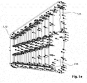
- Fig 5e the 3/4 view of a diversity antenna substrate with apertures and arrows showing pressure applied during finite element analysis, a calculation of the stiffness is done in simulation.
- a first simulation of static stress and displacement was performed by assuming substrate 101 is fixed at a mounting block location 315 (A) and subjected to an equivalent 15 km/hr wind load perpendicular to the flat plane of substrate 101.
- the substrate 101 material is fiberglass epoxy, about 0.12" thick as used in multilayer circuit boards and also log-periodic antennas which has an elastic modulus of about 3,499,760 psi or 2.413 X 10 ⁇ 10 N/m ⁇ 2.
- the highest displacement "B" 570 is about 0.3 mm, +/-10%.
- the modeled average pressure on the substrate is 146,000 N/m ⁇ 2, and a peak pressure of 878,374 N/m ⁇ 2 at a location corresponding to block location 315.
- FIG 5f a second simulation was performed using the cantilever beam method.
- the substrate which as the same material properties and dimensions as above, is affixed with two clamps (B) spaced apart and at equally spaced locations at the large parallel end of the trapezoid.
- Mass (C) having a dimension of 1.5 X 1.5 X 5" having a mass of 1.417 kg is placed on the horizontal distal end extending from the clamps.
- the deflection at the distal end is about 2.092 mm.
- the maximum stress is about 60,848,992 N/m ⁇ 2 around the nearest apertures (D). Without large aperture 547, the deflection is 1.795 mm and the maximum stress 52,441,268 N/m ⁇ 2.
- antenna systems as described herein may be used indoors or out of doors, and therefore subjected to rain.
- Rain on free space elements used in wire type antennas has little effect.
- the coating of water on a planar fin type antenna is more pronounced, having a significant detuning effect and reduction of operating efficiency relative to the extended dipole antenna.
- the touching of other objects such as poles, stage equipment and crossing lines are common in performance venues and tend to adversely affect bare or painted shark fin type antennas as commonly used today such as the Lectrosonics ALP500 LPDA Shark Fin Style Antenna.
- On-board electronics are best shielded from water which could cause corrosion, short circuits or other damage.
- FIG. 6a there is shown a 3/4 view of a dielectric air space hood for a diversity antenna with foldable whip elements 111 and 113 solves the problem of touching objects and rainwater detuning by providing an air space between the wet surface and the flat panel of the antenna patch.
- Hood 601 may be made of rubberized canvas material having a closed end 603, a tapered sewn edge 605 and an open end 607. Flap 609 and cover 611 allow ready attachment of cables (not shown) to connectors, and may be held in place using hook and loop fasteners for quick deployment.
- Aperture 613 permits ready connection and extension of whip 111.
- Aperture 613 may be extended to form a slit, if desired.
- Second aperture 614 may be provided to gain easy access to connectors.
- the hood 601 is so effective at regulating the operation of planar antennas that it could be left in place at all times, protecting the electrical components, thereby reducing the need for rubberized or epoxy painted conformal coatings, which are lossy at RF frequencies, and thus keeping rough or sharp edges from persons who may be injured by a falling, uncovered antenna. Flap 609 and cover 611 fold together to form a reasonably water resistant covering with an aperture 613 permitting the attachment of whip antennas 111 and 113 while maintaining performance. A further advantage of the dielectric air space hood 601 provides for user selectable colors, indicia, advertising, and easy machine wash cleaning.
- the diversity fin antenna thus described is uniquely suited to convenient, compact, one-step set up and deployment yet with a very high probability of obtaining a consistent signal and a very low probability of a dropout condition in the overall antenna. It would be desirable if the unique co-location of diversity elements and their desirable properties could be used at distances greater than afforded by relatively lossy coaxial cables.
- FIG 7a a block diagram of an RF over fiber system that is optimally configured with a diversity fin antenna, co-located antennas 701 and 702 are shown normally connected each to a converter box 703 and 704.
- Power from DC bus 705 energizes a circuit that modulates a locally-generated optical signal with the incoming RF signal from antennas 701 and 702, that is superimposed onto the optical signal (e.g., via a heterodyne method) and sent out over pair of fiber optic lines 707 and 708.
- Each channel is used in a diversity reception environment here consisting of both vertical and horizontal components as afforded by the orthogonal juxtaposition of receiving elements as taught generally herein.
- FIG 7b a more detailed block diagram of the RF over fiber system with feedback and inline filtering, one channel of RF energy is shown at shielded entry point 711 through the RF shield of conductive enclosure 713 which surrounds the sensitive electronics circuit 715 contained therein.
- RF amplifier 717 is fed with low level RF having a range of -150 dbm to about -20 dbm. Stronger signals than -20 dbm can overload the amplifier 717, which has a broadband response from below 100 MHz to above 1000 MHz.
- the amplified RF signal at the output of amplifier 717 is then connected to a plurality of switchable passband filters 719 and 721 before being injected into the laser diode 723.
- a feedback amplifier 725 senses the current at laser diode 723 and provides negative feedback to RF amplifier 717 to limit its range to within the linear operating range of the device.
- Passband filters 719 and 721 may be selectively switched into an on or off state via logic line 727 which is connected to a further CPU (not shown).
- a person of skill will appreciate that other aspects of the laser diode 723 may be sensed in place of, or in addition to, current, such as the fluence of the laser diode.
- a person of skill will also appreciate that other types of feedback may be provided instead of negative feedback, such as positive feedback.
- FIG 7c a pair of RF over fiber modules packaged for use with the diversity fin antenna and mounted thereto, antenna substrate panel 101 is fitted with converter boxes 703 and 704 mounted back-to-back, which reduces crosstalk.
- the RF over fiber conversion system shown in FIGs 7a , 7b and 7c maintain channel separation and have little sharing of components, and require two fiber optic lines to be connected to the diversity fin antenna.
- FIG 7d the block diagram of a conversion scheme using up and down conversion of the RF signal prior to transmission over an optical line, shows how this aspect can be used to eliminate the need for two optical lines.
- Co-located antennas 701 and 702 are amplified with tuned amplifiers 731 and 732, which are gain and noise figure optimized for the desired frequency range, which for the purpose of the techniques described herein can be illustrated as the 500 to 600 MHz band. Having amplifier gain optimized permits gain matching of the vertical and horizontal signals which may be different due to gain characteristics of the log-periodic type antenna vs the so-called "whip" antenna. Adjusting the RF gain relationships of the working elements affords a greater control of the antenna range, performance, and resistance to dropouts.
- the RF gain disparity is small and can be ignored since diversity receive systems vote for the channel with the highest signal level and lowest noise, and additionally the intentional mismatch of gain reduces the number of switching events which may cause noise, owing to the small imbalance of the RF energy from the log-periodic section, which has higher gain, vs the dipole array, which has lower gain.
- a typical gain adjustment is made by use of fixed resistors 733 and 734 which set the amplifier gain according to the resistance value chosen. Gain may be adjusted by the use of a variable potentiometer (not shown) in place of resistors 733 and 734 if gain needs to be adjusted at the board level frequently.
- amplified RF from each amplifier is fed into identical narrow band pass filters 735 and 736 each limiting signals to a specific range of frequencies with high attenuation outside those frequencies. For the purpose of illustration a range of 50MHz to 600 MHz is used.
- the filtered signal then passes into individual mixers 737 and 738.
- the type of mixer can be a double balanced mixer which has good port isolation and also a high dynamic range and low harmonics.
- Both mixers 737 and 738 are fed with one local oscillator 741 which is a high quality sine wave oscillator that is preferably crystal controlled.
- a local oscillator frequency of 100 MHz is used though it should be understood that other local oscillator frequencies may be used.
- a mixer will output the sum and difference between the local oscillator frequency and the incoming RF frequency or band of frequencies. Both sum and difference are present at the mixer output but usually radio receiver designers filter out one or the other. In the embodiments described herein, both sum and difference frequency components are used in a selective manner to accomplish the objective of carrying two channels of one frequency band over a single modulated optical fiber modulated with a simple RF amplifier and laser diode arrangement. Relative phase is preserved by the use of a common local oscillator and mixer and one resulting mixed produce can be inverted if needed to prevent the two results from occurring 180 degrees out of phase, depending on the mixer type used.
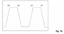
- the sum and difference frequency bands that result from the use of a 100 MHz local oscillator 741 when mixed with a frequency range of 500 to 600 MHz is 500 to 600 MHz and 600 to 700 MHz.
- Second stage bandpass filter 743 may therefore have a selected passband of 500 to 600 MHz.
- Second stage bandpass filter 745 may have a selected passband of 600 to 700 MHz. It can be seen that we have taken a 500 to 600 MHz band and split it into two different but separate bands each separated by 100 MHz in this instance.
- Local oscillator 741 100 MHz signal is used to convert and control both bands, with the advantage that slight drifts of the local oscillator will equally affect both bands.
- the local oscillator output is therefore important and used again as a pilot or reference signal over signal line 747 after being attenuated by resistor 749 and fed into laser diode 751 simultaneously with the filtered outputs of bandpass filters 743 and 745 with the result that two distinct bands of information may be non-interferingly carried on the modulated laser diode 751 signal with the local oscillator output also being present and capable of being referred to where needed, out through single fiber optic line 753.
- FIG 7e is a diagram of one possible resulting spectrum from the conversion scheme showing the passband reassigned to a plurality of frequency segments, when the steps in FIG 7d are carried out.
- each of the two co-located antennas are now shown to have their outputs converted via heterodyne method to a higher and a lower band separated by the local oscillator frequency.
- both signal bands can be injected into to modulate laser diode 751 and remain distinct and separable at the receiving converter end.
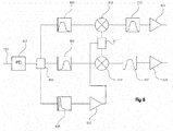
- FIG 8 is the block diagram of an optical receiving converter for converting a modulated lightwave signal having frequency spaced channels into a pair of matched frequency RF channels for use by a conventional diversity receiver.
- Fiber optic line 753 from the laser diode 751 of Fig. 7d is connected to receive photodiode 801 of Fig. 8 which has an RF output that is divided by three-way divider 803 and then into separate band pass filters 805, 807 and 809.
- bandpass filter 805 has a passband of 400 to 500 MHz which represents the "down" converted signal.
- Bandpass filter 807 has a passband of 600 to 700 MHz which represents the "up" converted signal.
- Band pass filter 809 has a very narrow passband centered on 100 MHz which is the local oscillator reference signal or pilot signal. Filter 809 is followed by amplifier 810 which boosts only that reference or pilot signal to a level that is used by 2-way power divider 811 and feeds into separate mixers 812 and 813 simultaneously. Outputs of mixers 812 and 813 which still have remnants of the 400 to 500 MHz and 600 to 700 MHz signals are each individually filtered at filters 815 and 817 to have identical passbands of 500 to 600 MHz , amplified if needed by amplifiers, but otherwise identical in frequency, amplitude and phase to the original signals prior to optical conversion and frequency band reassignment. The two signals are virtually identical to those that would be produced by a pair of coincident elements cross polarized and used in a probabilistic manner to assure at least one of the two inputs to a given receiver are never exposed to a cross polarization null result.
- a variation of the conversion scheme may include one in which a single RF line is used to interconnect the transmitting and receiving sections using essentially the same RF band reassignment techniques with a single local oscillator but with coaxial cable instead of optical cable. Having a single line do the work of two lines is advantageous, in both the RF and the optical domains.
- wavelength division multiplexing using a plurality of optical wavelengths to distribute multiple channels of information is an available technology but often has a cost that exceeds the embodiments described herein as the optical components for wavelength division multiplexing and demux are relatively high in cost.
- the embodiments can use much less costly components; Laser diodes capable of amplitude modulated operation up to 2 GHz are available for less than $25, for instance, and simple photodiodes capable of demodulating an AM optical carrier are also readily available, inexpensive, and simple to implement.
- the probabilistic diversity fin antenna system thus described with additional components is especially well suited for the application as it has adequate planar space for circuity, dual, co-located polarization, and is compact, light and portable.
- the subject matter described herein can therefore further be implemented as one or more computer program products, such as one or more computer programs tangibly embodied in an information carrier (e.g., in a machine readable storage device), or embodied in a propagated signal, for execution by, or to control the operation of, data processing apparatus (e.g., a programmable processor, a computer, or multiple computers).
- a computer program also known as a program, software, software application, or code
- the computer program can include, for example, web application software, scanning software, RF data analysis software (e.g., including the frequency allocation and intermodulation program), and user interlace software.
- a computer program does not necessarily correspond to a file.
- a program can be stored in a portion of a file that holds other programs or data, in a single file dedicated to the program in question, or in multiple coordinated files (e.g., files that store one or more modules, sub programs, or portions of code).
- a computer program can be deployed to be executed on one computer or on multiple computers 115 at one site or distributed across multiple sites and interconnected by a communication network.
- processors suitable for the execution of a computer program include, by way of example, both general and special purpose microprocessors, and any one or more processor of any kind of digital computer.
- a processor receives instructions and data from a read only memory or a random access memory or both.
- the essential elements of a computer are a processor for executing instructions and one or more memory devices for storing instructions and data.
- a computer also includes, or is operatively coupled to receive data from or transfer data to, or both, one or more mass storage devices for storing data, e.g., magnetic, magneto optical disks, or optical disks.
- Information carriers suitable for embodying computer program instructions and data include all forms of non-volatile memory, including by way of example semiconductor memory devices, (e.g., EPROM, EEPROM, and flash memory devices); magnetic disks, (e.g., internal hard disks or removable disks); magneto optical disks; and optical disks (e.g., CD and DVD disks).
- semiconductor memory devices e.g., EPROM, EEPROM, and flash memory devices
- magnetic disks e.g., internal hard disks or removable disks
- magneto optical disks e.g., CD and DVD disks
- optical disks e.g., CD and DVD disks.
- the processor and the memory can be supplemented by, or incorporated in, special purpose logic circuitry.
- the components of the system can be interconnected by any form or medium of digital data communication, e.g., a communication network.
- Examples of communication networks include a local area network (“LAN”) and a wide area network (“WAN”), e.g., the Internet.
- LAN local area network
- WAN wide area network
Landscapes
- Engineering & Computer Science (AREA)
- Computer Networks & Wireless Communication (AREA)
- Radar, Positioning & Navigation (AREA)
- Remote Sensing (AREA)
- Physics & Mathematics (AREA)
- Signal Processing (AREA)
- Electromagnetism (AREA)
- General Physics & Mathematics (AREA)
- Radio Transmission System (AREA)
- Variable-Direction Aerials And Aerial Arrays (AREA)
- Details Of Aerials (AREA)
Applications Claiming Priority (1)
| Application Number | Priority Date | Filing Date | Title |
|---|---|---|---|
| US15/727,506 US20190107617A1 (en) | 2017-10-06 | 2017-10-06 | Diversity fin antenna |
Publications (3)
| Publication Number | Publication Date |
|---|---|
| EP3270462A2 true EP3270462A2 (fr) | 2018-01-17 |
| EP3270462A3 EP3270462A3 (fr) | 2018-09-12 |
| EP3270462B1 EP3270462B1 (fr) | 2020-12-02 |
Family
ID=60190765
Family Applications (1)
| Application Number | Title | Priority Date | Filing Date |
|---|---|---|---|
| EP17199008.8A Active EP3270462B1 (fr) | 2017-10-06 | 2017-10-27 | Antenne de diversité à ailettes |
Country Status (2)
| Country | Link |
|---|---|
| US (2) | US20190107617A1 (fr) |
| EP (1) | EP3270462B1 (fr) |
Cited By (1)
| Publication number | Priority date | Publication date | Assignee | Title |
|---|---|---|---|---|
| EP3761443A1 (fr) * | 2019-06-26 | 2021-01-06 | Eagle Technology, LLC | Antenne ayant des ailettes d'antenne déployables et procédés associés |
Families Citing this family (4)
| Publication number | Priority date | Publication date | Assignee | Title |
|---|---|---|---|---|
| CA3087717A1 (fr) | 2018-02-27 | 2019-09-06 | Naeem Zafar | Procede et appareil pour la surveillance et la gestion a distance d'un contenant a l'aide de l'apprentissage machine et de l'analyse des donnees |
| DE102018116378A1 (de) * | 2018-07-06 | 2020-01-09 | Valeo Schalter Und Sensoren Gmbh | Verfahren zur Ermittlung von wenigstens einer Objektinformation wenigstens eines Zielobjekts, das mit einem Radarsystem insbesondere eines Fahrzeugs erfasst wird, Radarsystem und Fahrerassistenzsystem |
| AU2020377932A1 (en) | 2019-11-07 | 2022-05-26 | TeleSense, Inc. | Systems and methods for advanced grain storage and management using predictive analytics and anomaly detection |
| CN114709589A (zh) * | 2022-03-08 | 2022-07-05 | 陈驹畅 | 一种光学通讯系统接收天线 |
Citations (1)
| Publication number | Priority date | Publication date | Assignee | Title |
|---|---|---|---|---|
| US8836593B2 (en) | 2010-08-03 | 2014-09-16 | RF Venue, Inc | Diversity fin antenna |
Family Cites Families (16)
| Publication number | Priority date | Publication date | Assignee | Title |
|---|---|---|---|---|
| GB8410671D0 (en) * | 1984-04-26 | 1984-05-31 | British Telecomm | Transmitting stereo audio programmes |
| US4723321A (en) * | 1986-11-07 | 1988-02-02 | American Telephone And Telegraph Company, At&T Bell Laboratories | Techniques for cross-polarization cancellation in a space diversity radio system |
| US5325104A (en) * | 1990-01-03 | 1994-06-28 | Harada Kogyo Kabushiki Kaisha | Whip antenna for use in vehicles |
| EP0772312A3 (fr) * | 1990-09-14 | 1997-09-03 | Fujitsu Ltd | Système de communication optique avec multiplexage par sous-porteuses |
| CN1056255C (zh) * | 1993-01-30 | 2000-09-06 | 汤姆森电子消费品公司 | 变频器 |
| US5377035A (en) * | 1993-09-28 | 1994-12-27 | Hughes Aircraft Company | Wavelength division multiplexed fiber optic link for RF polarization diversity receiver |
| DE19607045A1 (de) * | 1996-02-24 | 1997-08-28 | Lindenmeier Heinz | Empfangsantennen-Scanningdiversitysystem für den Meterwellenbereich für Fahrzeuge |
| US5809049A (en) * | 1996-12-19 | 1998-09-15 | Lucent Technologies Inc. | Method and apparatus for monitoring the RF drive circuit of a linear laser transmitter |
| US6268946B1 (en) * | 1998-07-01 | 2001-07-31 | Radio Frequency Systems, Inc. | Apparatus for communicating diversity signals over a transmission medium |
| US20020114038A1 (en) * | 2000-11-09 | 2002-08-22 | Shlomi Arnon | Optical communication system |
| JP2003163634A (ja) * | 2001-11-27 | 2003-06-06 | Hitachi Kokusai Electric Inc | 副搬送波多重光伝送装置の光送信装置及び光受信装置 |
| US6833810B2 (en) * | 2002-01-18 | 2004-12-21 | Raytheon Company | Combining signals exhibiting multiple types of diversity |
| JP2005175826A (ja) * | 2003-12-10 | 2005-06-30 | Matsushita Electric Ind Co Ltd | 光ファイバ無線伝送システム、送信装置及び受信装置 |
| US7466082B1 (en) * | 2005-01-25 | 2008-12-16 | Streamlight, Inc. | Electronic circuit reducing and boosting voltage for controlling LED current |
| US8259834B2 (en) * | 2006-09-29 | 2012-09-04 | Broadcom Corporation | Method and system for OFDM based MIMO system with enhanced diversity |
| GB0817734D0 (en) * | 2008-09-26 | 2008-11-05 | Ucl Business Plc | Apparatus and method for transporting multiple signals over optical fiber |
-
2017
- 2017-10-06 US US15/727,506 patent/US20190107617A1/en not_active Abandoned
- 2017-10-27 EP EP17199008.8A patent/EP3270462B1/fr active Active
-
2020
- 2020-12-14 US US17/120,635 patent/US11802955B2/en active Active
Patent Citations (1)
| Publication number | Priority date | Publication date | Assignee | Title |
|---|---|---|---|---|
| US8836593B2 (en) | 2010-08-03 | 2014-09-16 | RF Venue, Inc | Diversity fin antenna |
Cited By (2)
| Publication number | Priority date | Publication date | Assignee | Title |
|---|---|---|---|---|
| EP3761443A1 (fr) * | 2019-06-26 | 2021-01-06 | Eagle Technology, LLC | Antenne ayant des ailettes d'antenne déployables et procédés associés |
| US11177576B2 (en) | 2019-06-26 | 2021-11-16 | Eagle Technology, Llc | Antenna having deployable antenna fins and associated methods |
Also Published As
| Publication number | Publication date |
|---|---|
| EP3270462B1 (fr) | 2020-12-02 |
| US20210181334A1 (en) | 2021-06-17 |
| EP3270462A3 (fr) | 2018-09-12 |
| US20190107617A1 (en) | 2019-04-11 |
| US11802955B2 (en) | 2023-10-31 |
Similar Documents
| Publication | Publication Date | Title |
|---|---|---|
| US11802955B2 (en) | Diversity fin antenna | |
| US6249254B1 (en) | Flat panel antenna | |
| US5264862A (en) | High-isolation collocated antenna systems | |
| US6836254B2 (en) | Antenna system | |
| US4538153A (en) | Directivity diversity communication system with microstrip antenna | |
| US7865213B2 (en) | Tuned directional antennas | |
| US8836593B2 (en) | Diversity fin antenna | |
| US6104356A (en) | Diversity antenna circuit | |
| US7577464B2 (en) | Compact antenna system for polarization sensitive null steering and direction-finding | |
| US6549168B1 (en) | GPS and telemetry microstrip antenna for use on projectiles | |
| CN109462024A (zh) | 一种宽轴比波束的双频北斗导航天线 | |
| US20140247194A1 (en) | Gnss antennas | |
| US4229744A (en) | Directional annular slot antenna | |
| US7333068B2 (en) | Planar anti-reflective interference antennas with extra-planar element extensions | |
| US10490901B2 (en) | Vivaldi antenna-based antenna system | |
| US20070109193A1 (en) | Anti-reflective interference antennas with radially-oriented elements | |
| US20200395686A1 (en) | Interference mitigation apparatus and method for a wireless terminal | |
| US7292201B2 (en) | Directional antenna system with multi-use elements | |
| US4005432A (en) | Commutated log periodic antenna array for automatic direction finding | |
| US20230299486A1 (en) | Antenna subarray and base station antenna | |
| US8217846B1 (en) | Low profile dual-polarized radiating element with coincident phase centers | |
| EP3832800B1 (fr) | Dispositif d'antenne et dispositif de communication | |
| Hofer et al. | Compact Multi-Polarized Broadband Antenna | |
| JPH11163585A (ja) | 電磁波制御板 | |
| US9397394B2 (en) | Antenna arrays with modified Yagi antenna units |
Legal Events
| Date | Code | Title | Description |
|---|---|---|---|
| PUAI | Public reference made under article 153(3) epc to a published international application that has entered the european phase |
Free format text: ORIGINAL CODE: 0009012 |
|
| STAA | Information on the status of an ep patent application or granted ep patent |
Free format text: STATUS: THE APPLICATION HAS BEEN PUBLISHED |
|
| AK | Designated contracting states |
Kind code of ref document: A2 Designated state(s): AL AT BE BG CH CY CZ DE DK EE ES FI FR GB GR HR HU IE IS IT LI LT LU LV MC MK MT NL NO PL PT RO RS SE SI SK SM TR |
|
| AX | Request for extension of the european patent |
Extension state: BA ME |
|
| RIC1 | Information provided on ipc code assigned before grant |
Ipc: H01Q 1/08 20060101ALI20180425BHEP Ipc: H01Q 25/00 20060101ALI20180425BHEP Ipc: H01Q 11/10 20060101AFI20180425BHEP Ipc: H01Q 23/00 20060101ALI20180425BHEP Ipc: H01Q 21/28 20060101ALI20180425BHEP Ipc: H01Q 9/40 20060101ALI20180425BHEP |
|
| PUAL | Search report despatched |
Free format text: ORIGINAL CODE: 0009013 |
|
| AK | Designated contracting states |
Kind code of ref document: A3 Designated state(s): AL AT BE BG CH CY CZ DE DK EE ES FI FR GB GR HR HU IE IS IT LI LT LU LV MC MK MT NL NO PL PT RO RS SE SI SK SM TR |
|
| AX | Request for extension of the european patent |
Extension state: BA ME |
|
| RIC1 | Information provided on ipc code assigned before grant |
Ipc: H01Q 9/40 20060101ALI20180807BHEP Ipc: H01Q 23/00 20060101ALI20180807BHEP Ipc: H01Q 25/00 20060101ALI20180807BHEP Ipc: H04B 10/2575 20130101ALI20180807BHEP Ipc: H01Q 11/10 20060101AFI20180807BHEP Ipc: H01Q 1/08 20060101ALI20180807BHEP Ipc: H01Q 21/28 20060101ALI20180807BHEP |
|
| STAA | Information on the status of an ep patent application or granted ep patent |
Free format text: STATUS: REQUEST FOR EXAMINATION WAS MADE |
|
| 17P | Request for examination filed |
Effective date: 20190312 |
|
| RBV | Designated contracting states (corrected) |
Designated state(s): AL AT BE BG CH CY CZ DE DK EE ES FI FR GB GR HR HU IE IS IT LI LT LU LV MC MK MT NL NO PL PT RO RS SE SI SK SM TR |
|
| REG | Reference to a national code |
Ref country code: DE Ref legal event code: R079 Ref document number: 602017028693 Country of ref document: DE Free format text: PREVIOUS MAIN CLASS: H01Q0011100000 Ipc: H04B0007080000 |
|
| GRAP | Despatch of communication of intention to grant a patent |
Free format text: ORIGINAL CODE: EPIDOSNIGR1 |
|
| STAA | Information on the status of an ep patent application or granted ep patent |
Free format text: STATUS: GRANT OF PATENT IS INTENDED |
|
| RIC1 | Information provided on ipc code assigned before grant |
Ipc: H04B 10/2575 20130101ALI20200507BHEP Ipc: H04B 7/10 20170101ALI20200507BHEP Ipc: H01Q 1/08 20060101ALI20200507BHEP Ipc: H01Q 23/00 20060101ALI20200507BHEP Ipc: H01Q 9/40 20060101ALI20200507BHEP Ipc: H01Q 11/10 20060101ALI20200507BHEP Ipc: H01Q 21/28 20060101ALI20200507BHEP Ipc: H01Q 25/00 20060101ALI20200507BHEP Ipc: H04B 7/08 20060101AFI20200507BHEP |
|
| INTG | Intention to grant announced |
Effective date: 20200529 |
|
| GRAS | Grant fee paid |
Free format text: ORIGINAL CODE: EPIDOSNIGR3 |
|
| GRAA | (expected) grant |
Free format text: ORIGINAL CODE: 0009210 |
|
| STAA | Information on the status of an ep patent application or granted ep patent |
Free format text: STATUS: THE PATENT HAS BEEN GRANTED |
|
| AK | Designated contracting states |
Kind code of ref document: B1 Designated state(s): AL AT BE BG CH CY CZ DE DK EE ES FI FR GB GR HR HU IE IS IT LI LT LU LV MC MK MT NL NO PL PT RO RS SE SI SK SM TR |
|
| REG | Reference to a national code |
Ref country code: GB Ref legal event code: FG4D |
|
| REG | Reference to a national code |
Ref country code: AT Ref legal event code: REF Ref document number: 1342061 Country of ref document: AT Kind code of ref document: T Effective date: 20201215 Ref country code: CH Ref legal event code: EP |
|
| REG | Reference to a national code |
Ref country code: IE Ref legal event code: FG4D |
|
| REG | Reference to a national code |
Ref country code: DE Ref legal event code: R096 Ref document number: 602017028693 Country of ref document: DE |
|
| PG25 | Lapsed in a contracting state [announced via postgrant information from national office to epo] |
Ref country code: GR Free format text: LAPSE BECAUSE OF FAILURE TO SUBMIT A TRANSLATION OF THE DESCRIPTION OR TO PAY THE FEE WITHIN THE PRESCRIBED TIME-LIMIT Effective date: 20210303 Ref country code: FI Free format text: LAPSE BECAUSE OF FAILURE TO SUBMIT A TRANSLATION OF THE DESCRIPTION OR TO PAY THE FEE WITHIN THE PRESCRIBED TIME-LIMIT Effective date: 20201202 Ref country code: RS Free format text: LAPSE BECAUSE OF FAILURE TO SUBMIT A TRANSLATION OF THE DESCRIPTION OR TO PAY THE FEE WITHIN THE PRESCRIBED TIME-LIMIT Effective date: 20201202 Ref country code: NO Free format text: LAPSE BECAUSE OF FAILURE TO SUBMIT A TRANSLATION OF THE DESCRIPTION OR TO PAY THE FEE WITHIN THE PRESCRIBED TIME-LIMIT Effective date: 20210302 |
|
| REG | Reference to a national code |
Ref country code: NL Ref legal event code: MP Effective date: 20201202 |
|
| REG | Reference to a national code |
Ref country code: AT Ref legal event code: MK05 Ref document number: 1342061 Country of ref document: AT Kind code of ref document: T Effective date: 20201202 |
|
| PG25 | Lapsed in a contracting state [announced via postgrant information from national office to epo] |
Ref country code: SE Free format text: LAPSE BECAUSE OF FAILURE TO SUBMIT A TRANSLATION OF THE DESCRIPTION OR TO PAY THE FEE WITHIN THE PRESCRIBED TIME-LIMIT Effective date: 20201202 Ref country code: BG Free format text: LAPSE BECAUSE OF FAILURE TO SUBMIT A TRANSLATION OF THE DESCRIPTION OR TO PAY THE FEE WITHIN THE PRESCRIBED TIME-LIMIT Effective date: 20210302 Ref country code: PL Free format text: LAPSE BECAUSE OF FAILURE TO SUBMIT A TRANSLATION OF THE DESCRIPTION OR TO PAY THE FEE WITHIN THE PRESCRIBED TIME-LIMIT Effective date: 20201202 Ref country code: LV Free format text: LAPSE BECAUSE OF FAILURE TO SUBMIT A TRANSLATION OF THE DESCRIPTION OR TO PAY THE FEE WITHIN THE PRESCRIBED TIME-LIMIT Effective date: 20201202 |
|
| PG25 | Lapsed in a contracting state [announced via postgrant information from national office to epo] |
Ref country code: NL Free format text: LAPSE BECAUSE OF FAILURE TO SUBMIT A TRANSLATION OF THE DESCRIPTION OR TO PAY THE FEE WITHIN THE PRESCRIBED TIME-LIMIT Effective date: 20201202 Ref country code: HR Free format text: LAPSE BECAUSE OF FAILURE TO SUBMIT A TRANSLATION OF THE DESCRIPTION OR TO PAY THE FEE WITHIN THE PRESCRIBED TIME-LIMIT Effective date: 20201202 |
|
| REG | Reference to a national code |
Ref country code: LT Ref legal event code: MG9D |
|
| PG25 | Lapsed in a contracting state [announced via postgrant information from national office to epo] |
Ref country code: RO Free format text: LAPSE BECAUSE OF FAILURE TO SUBMIT A TRANSLATION OF THE DESCRIPTION OR TO PAY THE FEE WITHIN THE PRESCRIBED TIME-LIMIT Effective date: 20201202 Ref country code: PT Free format text: LAPSE BECAUSE OF FAILURE TO SUBMIT A TRANSLATION OF THE DESCRIPTION OR TO PAY THE FEE WITHIN THE PRESCRIBED TIME-LIMIT Effective date: 20210405 Ref country code: SK Free format text: LAPSE BECAUSE OF FAILURE TO SUBMIT A TRANSLATION OF THE DESCRIPTION OR TO PAY THE FEE WITHIN THE PRESCRIBED TIME-LIMIT Effective date: 20201202 Ref country code: SM Free format text: LAPSE BECAUSE OF FAILURE TO SUBMIT A TRANSLATION OF THE DESCRIPTION OR TO PAY THE FEE WITHIN THE PRESCRIBED TIME-LIMIT Effective date: 20201202 Ref country code: EE Free format text: LAPSE BECAUSE OF FAILURE TO SUBMIT A TRANSLATION OF THE DESCRIPTION OR TO PAY THE FEE WITHIN THE PRESCRIBED TIME-LIMIT Effective date: 20201202 Ref country code: CZ Free format text: LAPSE BECAUSE OF FAILURE TO SUBMIT A TRANSLATION OF THE DESCRIPTION OR TO PAY THE FEE WITHIN THE PRESCRIBED TIME-LIMIT Effective date: 20201202 Ref country code: LT Free format text: LAPSE BECAUSE OF FAILURE TO SUBMIT A TRANSLATION OF THE DESCRIPTION OR TO PAY THE FEE WITHIN THE PRESCRIBED TIME-LIMIT Effective date: 20201202 |
|
| PG25 | Lapsed in a contracting state [announced via postgrant information from national office to epo] |
Ref country code: AT Free format text: LAPSE BECAUSE OF FAILURE TO SUBMIT A TRANSLATION OF THE DESCRIPTION OR TO PAY THE FEE WITHIN THE PRESCRIBED TIME-LIMIT Effective date: 20201202 |
|
| REG | Reference to a national code |
Ref country code: DE Ref legal event code: R097 Ref document number: 602017028693 Country of ref document: DE |
|
| PG25 | Lapsed in a contracting state [announced via postgrant information from national office to epo] |
Ref country code: IS Free format text: LAPSE BECAUSE OF FAILURE TO SUBMIT A TRANSLATION OF THE DESCRIPTION OR TO PAY THE FEE WITHIN THE PRESCRIBED TIME-LIMIT Effective date: 20210402 |
|
| PLBE | No opposition filed within time limit |
Free format text: ORIGINAL CODE: 0009261 |
|
| STAA | Information on the status of an ep patent application or granted ep patent |
Free format text: STATUS: NO OPPOSITION FILED WITHIN TIME LIMIT |
|
| PG25 | Lapsed in a contracting state [announced via postgrant information from national office to epo] |
Ref country code: AL Free format text: LAPSE BECAUSE OF FAILURE TO SUBMIT A TRANSLATION OF THE DESCRIPTION OR TO PAY THE FEE WITHIN THE PRESCRIBED TIME-LIMIT Effective date: 20201202 |
|
| 26N | No opposition filed |
Effective date: 20210903 |
|
| PG25 | Lapsed in a contracting state [announced via postgrant information from national office to epo] |
Ref country code: DK Free format text: LAPSE BECAUSE OF FAILURE TO SUBMIT A TRANSLATION OF THE DESCRIPTION OR TO PAY THE FEE WITHIN THE PRESCRIBED TIME-LIMIT Effective date: 20201202 Ref country code: SI Free format text: LAPSE BECAUSE OF FAILURE TO SUBMIT A TRANSLATION OF THE DESCRIPTION OR TO PAY THE FEE WITHIN THE PRESCRIBED TIME-LIMIT Effective date: 20201202 |
|
| PG25 | Lapsed in a contracting state [announced via postgrant information from national office to epo] |
Ref country code: ES Free format text: LAPSE BECAUSE OF FAILURE TO SUBMIT A TRANSLATION OF THE DESCRIPTION OR TO PAY THE FEE WITHIN THE PRESCRIBED TIME-LIMIT Effective date: 20201202 |
|
| REG | Reference to a national code |
Ref country code: CH Ref legal event code: PL |
|
| PG25 | Lapsed in a contracting state [announced via postgrant information from national office to epo] |
Ref country code: IS Free format text: LAPSE BECAUSE OF FAILURE TO SUBMIT A TRANSLATION OF THE DESCRIPTION OR TO PAY THE FEE WITHIN THE PRESCRIBED TIME-LIMIT Effective date: 20210402 |
|
| REG | Reference to a national code |
Ref country code: BE Ref legal event code: MM Effective date: 20211031 |
|
| PG25 | Lapsed in a contracting state [announced via postgrant information from national office to epo] |
Ref country code: MC Free format text: LAPSE BECAUSE OF FAILURE TO SUBMIT A TRANSLATION OF THE DESCRIPTION OR TO PAY THE FEE WITHIN THE PRESCRIBED TIME-LIMIT Effective date: 20201202 |
|
| PG25 | Lapsed in a contracting state [announced via postgrant information from national office to epo] |
Ref country code: LU Free format text: LAPSE BECAUSE OF NON-PAYMENT OF DUE FEES Effective date: 20211027 Ref country code: BE Free format text: LAPSE BECAUSE OF NON-PAYMENT OF DUE FEES Effective date: 20211031 |
|
| PG25 | Lapsed in a contracting state [announced via postgrant information from national office to epo] |
Ref country code: LI Free format text: LAPSE BECAUSE OF NON-PAYMENT OF DUE FEES Effective date: 20211031 Ref country code: CH Free format text: LAPSE BECAUSE OF NON-PAYMENT OF DUE FEES Effective date: 20211031 |
|
| PG25 | Lapsed in a contracting state [announced via postgrant information from national office to epo] |
Ref country code: FR Free format text: LAPSE BECAUSE OF NON-PAYMENT OF DUE FEES Effective date: 20211031 |
|
| PG25 | Lapsed in a contracting state [announced via postgrant information from national office to epo] |
Ref country code: IE Free format text: LAPSE BECAUSE OF NON-PAYMENT OF DUE FEES Effective date: 20211027 |
|
| PG25 | Lapsed in a contracting state [announced via postgrant information from national office to epo] |
Ref country code: HU Free format text: LAPSE BECAUSE OF FAILURE TO SUBMIT A TRANSLATION OF THE DESCRIPTION OR TO PAY THE FEE WITHIN THE PRESCRIBED TIME-LIMIT; INVALID AB INITIO Effective date: 20171027 |
|
| PG25 | Lapsed in a contracting state [announced via postgrant information from national office to epo] |
Ref country code: CY Free format text: LAPSE BECAUSE OF FAILURE TO SUBMIT A TRANSLATION OF THE DESCRIPTION OR TO PAY THE FEE WITHIN THE PRESCRIBED TIME-LIMIT Effective date: 20201202 |
|
| REG | Reference to a national code |
Ref country code: DE Ref legal event code: R082 Ref document number: 602017028693 Country of ref document: DE Representative=s name: BRAEUNING & SCHUBERT PATENTANWAELTE GBR, DE Ref country code: DE Ref legal event code: R082 Ref document number: 602017028693 Country of ref document: DE Representative=s name: BRAEUNING & SCHUBERT PATENTANWAELTE, DE |
|
| PGFP | Annual fee paid to national office [announced via postgrant information from national office to epo] |
Ref country code: GB Payment date: 20231025 Year of fee payment: 7 |
|
| PGFP | Annual fee paid to national office [announced via postgrant information from national office to epo] |
Ref country code: IT Payment date: 20231031 Year of fee payment: 7 Ref country code: DE Payment date: 20231024 Year of fee payment: 7 |
|
| PG25 | Lapsed in a contracting state [announced via postgrant information from national office to epo] |
Ref country code: MK Free format text: LAPSE BECAUSE OF FAILURE TO SUBMIT A TRANSLATION OF THE DESCRIPTION OR TO PAY THE FEE WITHIN THE PRESCRIBED TIME-LIMIT Effective date: 20201202 |
|
| PG25 | Lapsed in a contracting state [announced via postgrant information from national office to epo] |
Ref country code: MT Free format text: LAPSE BECAUSE OF FAILURE TO SUBMIT A TRANSLATION OF THE DESCRIPTION OR TO PAY THE FEE WITHIN THE PRESCRIBED TIME-LIMIT Effective date: 20201202 |