EP3270114A1 - Sensoranordnung - Google Patents
Sensoranordnung Download PDFInfo
- Publication number
- EP3270114A1 EP3270114A1 EP16179633.9A EP16179633A EP3270114A1 EP 3270114 A1 EP3270114 A1 EP 3270114A1 EP 16179633 A EP16179633 A EP 16179633A EP 3270114 A1 EP3270114 A1 EP 3270114A1
- Authority
- EP
- European Patent Office
- Prior art keywords
- sensor
- arrangement according
- sensor arrangement
- offset
- mark
- Prior art date
- Legal status (The legal status is an assumption and is not a legal conclusion. Google has not performed a legal analysis and makes no representation as to the accuracy of the status listed.)
- Granted
Links
Images


Classifications
-
- G—PHYSICS
- G01—MEASURING; TESTING
- G01D—MEASURING NOT SPECIALLY ADAPTED FOR A SPECIFIC VARIABLE; ARRANGEMENTS FOR MEASURING TWO OR MORE VARIABLES NOT COVERED IN A SINGLE OTHER SUBCLASS; TARIFF METERING APPARATUS; MEASURING OR TESTING NOT OTHERWISE PROVIDED FOR
- G01D5/00—Mechanical means for transferring the output of a sensing member; Means for converting the output of a sensing member to another variable where the form or nature of the sensing member does not constrain the means for converting; Transducers not specially adapted for a specific variable
- G01D5/26—Mechanical means for transferring the output of a sensing member; Means for converting the output of a sensing member to another variable where the form or nature of the sensing member does not constrain the means for converting; Transducers not specially adapted for a specific variable characterised by optical transfer means, i.e. using infrared, visible, or ultraviolet light
- G01D5/32—Mechanical means for transferring the output of a sensing member; Means for converting the output of a sensing member to another variable where the form or nature of the sensing member does not constrain the means for converting; Transducers not specially adapted for a specific variable characterised by optical transfer means, i.e. using infrared, visible, or ultraviolet light with attenuation or whole or partial obturation of beams of light
- G01D5/34—Mechanical means for transferring the output of a sensing member; Means for converting the output of a sensing member to another variable where the form or nature of the sensing member does not constrain the means for converting; Transducers not specially adapted for a specific variable characterised by optical transfer means, i.e. using infrared, visible, or ultraviolet light with attenuation or whole or partial obturation of beams of light the beams of light being detected by photocells
- G01D5/347—Mechanical means for transferring the output of a sensing member; Means for converting the output of a sensing member to another variable where the form or nature of the sensing member does not constrain the means for converting; Transducers not specially adapted for a specific variable characterised by optical transfer means, i.e. using infrared, visible, or ultraviolet light with attenuation or whole or partial obturation of beams of light the beams of light being detected by photocells using displacement encoding scales
- G01D5/34776—Absolute encoders with analogue or digital scales
-
- G—PHYSICS
- G01—MEASURING; TESTING
- G01D—MEASURING NOT SPECIALLY ADAPTED FOR A SPECIFIC VARIABLE; ARRANGEMENTS FOR MEASURING TWO OR MORE VARIABLES NOT COVERED IN A SINGLE OTHER SUBCLASS; TARIFF METERING APPARATUS; MEASURING OR TESTING NOT OTHERWISE PROVIDED FOR
- G01D5/00—Mechanical means for transferring the output of a sensing member; Means for converting the output of a sensing member to another variable where the form or nature of the sensing member does not constrain the means for converting; Transducers not specially adapted for a specific variable
- G01D5/12—Mechanical means for transferring the output of a sensing member; Means for converting the output of a sensing member to another variable where the form or nature of the sensing member does not constrain the means for converting; Transducers not specially adapted for a specific variable using electric or magnetic means
- G01D5/244—Mechanical means for transferring the output of a sensing member; Means for converting the output of a sensing member to another variable where the form or nature of the sensing member does not constrain the means for converting; Transducers not specially adapted for a specific variable using electric or magnetic means influencing characteristics of pulses or pulse trains; generating pulses or pulse trains
- G01D5/24457—Failure detection
- G01D5/24466—Comparison of the error value to a threshold
-
- G—PHYSICS
- G01—MEASURING; TESTING
- G01D—MEASURING NOT SPECIALLY ADAPTED FOR A SPECIFIC VARIABLE; ARRANGEMENTS FOR MEASURING TWO OR MORE VARIABLES NOT COVERED IN A SINGLE OTHER SUBCLASS; TARIFF METERING APPARATUS; MEASURING OR TESTING NOT OTHERWISE PROVIDED FOR
- G01D5/00—Mechanical means for transferring the output of a sensing member; Means for converting the output of a sensing member to another variable where the form or nature of the sensing member does not constrain the means for converting; Transducers not specially adapted for a specific variable
- G01D5/12—Mechanical means for transferring the output of a sensing member; Means for converting the output of a sensing member to another variable where the form or nature of the sensing member does not constrain the means for converting; Transducers not specially adapted for a specific variable using electric or magnetic means
- G01D5/244—Mechanical means for transferring the output of a sensing member; Means for converting the output of a sensing member to another variable where the form or nature of the sensing member does not constrain the means for converting; Transducers not specially adapted for a specific variable using electric or magnetic means influencing characteristics of pulses or pulse trains; generating pulses or pulse trains
- G01D5/245—Mechanical means for transferring the output of a sensing member; Means for converting the output of a sensing member to another variable where the form or nature of the sensing member does not constrain the means for converting; Transducers not specially adapted for a specific variable using electric or magnetic means influencing characteristics of pulses or pulse trains; generating pulses or pulse trains using a variable number of pulses in a train
- G01D5/2454—Encoders incorporating incremental and absolute signals
Definitions
- the invention relates to a sensor arrangement.
- Such a sensor arrangement can be formed, for example, by a position sensor in the form of a distance sensor with which the distance to a cooperative target, such as a reflector, is measured.
- the distance sensor can be an optical sensor with a light beam emitting transmitter and a light beam receiving receiver, wherein the distance measurement can be carried out according to the phase measurement principle or with a pulse transit time method.
- the sensor arrangement may comprise a position sensor in the form of a code reader, in particular a bar code reader, wherein the cooperative target is then formed in the form of a tag with a code, wherein a position information is coded in the code.
- Such a sensor arrangement is known from DE 199 10 933 B4 known.
- This sensor arrangement serves to position a vehicle on a stationary object, wherein the vehicle is movable along a predetermined path along the object.
- Coding-bearing marks are attached to the objects at predetermined intervals and can be detected on the vehicle by means of an optical sensor, the codings of the marks being recorded one after the other and the measured values recorded thereby being stored as reference values for absolute positioning of the vehicle during a reference run.
- a device having a position measuring system formed by an array of marks and an optical sensor for detecting the marks of the position measuring system.
- the optical sensor and the position measuring system are arranged to be movable relative to one another.
- Each brand contains its absolute position within the position measurement system as a coding.
- a sensor element is permanently assigned to the optical sensor for forming a two-channel, diverse sensor system, by means of which the marks of the position measuring system or markings of an incremental measuring system fixedly assigned to the position measuring system can be detected.
- the signals generated by the optical sensor and by the sensor element are compared with each other in a redundant evaluation system, whereby errors in the optical sensor or in the sensor element can be revealed.
- the invention has the object of providing a sensor arrangement of the type mentioned in such a way that it has a high functionality and high reliability.
- the invention relates to a sensor arrangement having a first position sensor and a first cooperative target associated therewith, which delimit a detection area. Position measurements are used to obtain first position measurement values against the first cooperative target with the first position sensor. Furthermore, a second position sensor and a second cooperative target associated therewith are provided which delimit the detection area. By taking position measurements with the second position sensor against the second cooperative target, second position measurements are obtained. With a control unit, In which the first and second position measurement values of the two position sensors are calculated to a transfer quantity, the function of the position sensors is controlled.
- the sensor arrangement according to the invention has two sensor systems operating independently of one another, which in terms of their structure correspond to one another in that they each have a position sensor and an associated cooperative target.
- the sensor arrangement according to the invention Due to the continuous control of the charge quantity, in particular by a reference value comparison, it can be easily checked whether the position sensors are operating faultlessly or not. This results in a high reliability of the sensor arrangement according to the invention.
- the calculation of the amount of the calculation based on the position measurement values of the two position sensors takes place in the control unit, which can have a fail-safe, in particular redundant structure in order to increase the functional reliability.
- the sensor arrangements have two independent sensor systems each with a position sensor and a cooperative target, different configurations and arrangement of the sensor systems are possible.
- the position sensors can be arranged on the same edge of the detection area or on opposite edges of the detection area.
- the amount of offset can also be selected appropriately.
- the offset quantity may be the sum or the difference of the first and second position measurement values.
- the sensor arrangement is designed with its components in such a way that the sum or difference of the first and second position measurement values is constant in time, so that the control of the accounting variable is reduced to a setpoint comparison which can be carried out particularly easily.
- a fault-free function of the position sensor is given if the charge size is constant in time within a predetermined tolerance band.
- At least one position sensor is formed by an optical sensor which emits and receives light beams.
- the position sensor may be formed as a distance sensor, which operates, for example, according to a phase measurement method or a pulse transit time method.
- this distance sensor then advantageously carried out distance measurements against a reflector, in particular a retroreflector, as a cooperative target.
- a measuring path can be precisely and accurately controlled.
- the distance sensors can optionally be arranged on the same side of the measuring path or on opposite sides of the measuring path.
- the position sensor can be formed by an optical sensor by means of which codes containing codes can be read as the cooperative target, the codes preferably containing position information.
- the optical sensor is then advantageously designed as a bar code reader.
- At least one position sensor is an electromagnetic waves emitting in the radio or radar range and receiving sensor.
- the cooperative target is expediently at least one transponder, wherein position information is advantageously stored in the transponder.
- two similar such position sensors can be used in the sensor arrangement.
- this can be combined with a position sensor in the form of an optical sensor.
- the control unit of the sensor arrangement can advantageously be formed by a computer unit.
- This computer unit can be locally spatially assigned to the position sensors or be present in a decentralized manner in a cloud. Alternatively it can be provided as a control unit, a frequency converter.
- the position sensors are connected to the controller via identical or different interfaces.
- the position sensors are connected via a bidirectional data connection.
- the bidirectional data connection is formed by a bidirectional data line.
- each position sensor has a switching output and a switching input, wherein in each case a unidirectional data line is led from the switching output of a position sensor to the switching input of the other position sensor.
- the first and the second cooperative destination are each formed by a position measuring system consisting of a linear arrangement of position markers.
- the position marks encode their positions within the position measurement system.
- the position of the position sensor By continuously reading the position mark with the associated position sensor, the position of the position sensor can thus be detected time-resolved relative to the position measuring system. Due to the redundancy of the measured value acquisition by means of two position sensors, the reliability of the sensor arrangement is considerably increased.
- a particularly advantageous application is that the position measuring systems are arranged stationary, and that the position sensors are arranged on a vehicle.
- the vehicle By reading the position marks by means of the position sensors, the vehicle can be positioned exactly on the position measuring system and thus on an object on which the position measuring system is mounted.
- the vehicle can be formed by a stacker crane, a monorail conveyor or the like.
- test marks are present in the position measurement system, with a self-test being initiated when reading a test mark by means of a position sensor.
- test marks are distributed at equidistant intervals over the position measuring system, so that at constant speeds of the vehicle, the position sensors are tested continuously at regular intervals.
- each position measuring system is formed by an annular position measuring tape whose beginning and end are connected via an offset mark.
- each position measuring system is formed from a plurality of position measuring tapes.
- the end of a position measuring tape is connected via an offset mark with the beginning of a second position measuring tape.
- the first time the offset mark is detected with a first position sensor the offset of the position measurement value immediately before and after the offset mark is determined.
- the subsequent position measurement values of the first position sensor are corrected with the offset until the offset mark with the second position sensor is detected.
- FIG. 1 schematically shows an embodiment of the sensor arrangement according to the invention 1.
- the sensor assembly 1 is used for accurate positioning of a vehicle 2 relative to a stationary object 3.
- the vehicle 2 is formed by a storage and retrieval unit, which is positioned on a shelf.
- the position sensors 4a, 4b are formed in the present case as optical sensors and specifically as a bar code reader.
- Each position sensor 4a, 4b comprises a transmitter emitting light beams 5a, 5b, receivers receiving light beams 5a, 5b, and an evaluation unit in which codes are detected as a function of the received signals of the receiver.
- the position sensor 4a, 4b can be designed as a scanner.
- the position sensor 4a, 4b has a deflection unit such as a motor-driven rotating polygon mirror wheel which periodically deflects the light beams 5a, 5b emitting from the transmitter within a scanning range.
- the receiver may be formed by a single photodiode.
- the position sensor 4a, 4b as a receiver may comprise an image sensor such as a CCD or CMOS matrix, on which the code to be detected is mapped. In this case, no deflection unit is needed.
- Each position sensor 4a, 4b is assigned as a cooperative target a position measuring system 6a, 6b, which consists of one or more position measuring tapes.
- Each position measuring tape extends in the present case along a straight line, the position measuring systems 6a, 6b extending parallel to one another.
- the position measuring systems 6a, 6b are continuously scanned by respective position sensors 4a, 4b.
- the position sensors 4a, 4b of the sensor assembly 1 are connected to a control unit 7, which is formed in the present case by a computer unit.
- the computer unit can have a fail-safe, redundant structure.
- the control unit 7 may also be provided in a cloud.
- the control unit 7 may be formed by a frequency converter.
- Each position sensor 4a, 4b is connected to the control unit 7 via its interface 8a, 8b.
- the interfaces 8a, 8b may be identical or different. Examples of such interfaces 8a, 8b are EtherCat, ProfiSafe and Safe SSI interfaces.
- a direct bidirectional data connection between the two position sensors 4a, 4b is provided so that they can communicate directly with one another.
- This data connection can be formed by a bidirectional data line 9a, 9b.
- the first position sensor 4a has a switching output and a switching input.
- the second position sensor 4b has a switching output and a switching input.
- a unidirectional data line 9a, 9b is led to the switching input of the respective other position sensor 4b from each switching output O1, 02 of a position sensor 4a.
- the sensor arrangement 1 generally operates in such a way that position measurement values are continuously determined by the detection of the cooperative target with the position sensors 4a, 4b, the position measurement values of both position sensors 4a, 4b being offset in the control unit 7 to a transfer quantity. By a setpoint comparison of the settlement size is determined in the control unit 7, if the position sensors 4a, 4b work properly.
- each position measurement system 6a, 6b consists of a linear arrangement of position marks 10a, 10b, each position mark 10a, 10b containing a code in which its position is encoded within the position measurement system 6a, 6b.
- the positional quantities which are advantageously formed by the sum or difference of the position measurement values are then formed from the position measurement values recorded simultaneously with the position sensors 4a, 4b.
- An error-free operation of the position sensors 4a, 4b is present when the determined offset quantity within a predetermined tolerance band coincides with a setpoint stored in the control unit 7.
- test marks may be provided in the position measurement systems 6a, 6b, preferably at equidistant intervals. As soon as a position sensor 4a reads such a test mark, a self-test is initiated in it, by means of which it is possible to check whether the position sensor 4a, 4b operates without errors. The result of this check is sent from the position sensor 4a, 4b to the control unit 7.
- FIG. 3 shows a first embodiment of the position measuring systems 6a, 6b for the sensor assembly 1 according to FIG. 1 .
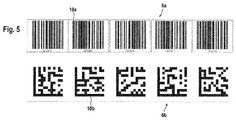
- the position markers 10a, 10b of both position measuring systems 6a, 6b are formed by bar codes, so that accordingly the position sensors 4a, 4b are formed by scanning bar code readers.
- the position marks 10a of the first position measuring system 6a numerical values ascending from left to right are encoded as position information.
- position marks 10b of the second position measuring system 6b numerical values descending from left to right are coded as position information.
- the two position sensors 4a, 4b are always two superimposed position marks 10a, 10b detected. Since the position markers 10a encode ascending numerical values and the position markers 10b encode declining numerical values, the sum of the numerical values and thus the position measurement values is always constant. This sum is checked as a settlement amount in the control unit 7 by a setpoint comparison.
- the position sensors 4a, 4b are advantageously mounted at different heights on the vehicle 2.
- the position marks 10a of the first position measuring system 6a may be shown in a different color than the position marks 10b of the second position measuring system 6b.
- the position sensors 4a, 4b can emit light of different wavelengths, so that the position sensor 4a can read only the position mark 10a and the position sensor 4b read only the position mark 10b.
- FIG. 4 differs from the arrangement of FIG. 5 only in that the position marks 10a of the first position measuring system 6a are arranged slightly offset from the position marks 10b of the second position measuring system 6b. Since the offset corresponds to only about half of a width of the position marks 10a, 10b, pairs of position marks 10a, 10b are always detected by the position sensors 4a, 4b, so that the position determination is completely analogous to the exemplary embodiment according to FIG FIG. 3 he follows.
- the arrangement of FIG. 5 differs from the arrangement of FIG. 3 only in that the position mark 10b of the position measuring system 6b are formed not by barcodes but by 2D codes. These are read by a position sensor 4a, 4b, which has an image sensor as a receiver. Otherwise, the evaluation is carried out analogously to the embodiment according to FIG. 3 ,
- the 2D codes may be formed as data matrix codes, QR codes, Atztec codes and the like.
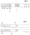
- the position marks 10a of the first position measuring system 6a and the position marks 10b of the second position measuring system 6b are provided in a linear arrangement, wherein the position marks 10a, 10b are always arranged side by side in pairs.
- the position sensors 4a, 4b are arranged at a distance one behind the other, so that with the position sensor 4a position marks 10a in a detection area A and simultaneously with the position sensor 4b position marks 10b detected in a detection area B.
- the sum of the position measurement values is then formed as a calculation quantity from the position measurement values for a pair of position markers 10a, 10b which are simultaneously recorded.
- position marks 10a provided (upper row in FIG. 7 ), which are again formed as barcodes and are read by a position sensor 4a in the form of an optical sensor.
- a series arrangement of position marks 10b is provided, which form a second position measuring system 6b, wherein the position marks 10b are formed by transponders in the form of RFID tags.
- position markers 10b are read by a position sensor 4b which has a transmitting / receiving unit emitting electromagnetic waves in the radio or radar range.
- numbers are encoded in ascending order in the position markers 10a as position information, whereas in the position markers 10b numbers are encoded as position information in decreasing order.
- the position sensors 4a, 4b always detect at the same time a pair of position marks 10a, 10b, which are arranged opposite to the front and back of the position measuring tape. The sum of the position measurement values recorded in this process is constant and is controlled as a settlement quantity.
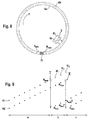
- FIG. 8 shows a variant of the embodiment of FIG. 3 in such a way that the position measuring systems 6a, 6b are arranged annularly.
- the position markers 10a, 10b each contain identical numbers as position information, which increase in the direction indicated by the arrow from a value N min to a value N max .
- N max is an offset mark 11.
- FIG. 8 is still the vehicle 2 with the position sensors 4a, 4b shown, which rotates in the arrow direction.
- the vehicle 2 approaches the position marks 10a, 10b with the maximum values N max .
- N max the maximum values
- the position measurement values (A1, A2) formed by number sequences increase in regular steps.
- the difference between the position measured values is constant and is controlled as a calculation quantity.
- the offset mark is detected. This reports the position sensor 4a via the switching output O1 to the position sensor 4b. During the next scan of the position sensor 4a, it registers the position mark 10a with the value N min . From the difference N max - N min an offset is formed.
- the position marks on it, determined with the position sensor 4a N min + 1, N min + have 2 as the position measurement value N min a jump over the position measurement value in the region a, so that so that the difference of the position measurement values of the position sensors 4a, 4b in the region b, so as long as the offset mark has not yet been detected with the position sensors 4b, is no longer constant.
- the position measurement values become of the position sensor 4a renormalized with the offset.
- These renormalized position measurements (in FIG. 9 denoted by N 1 ', N 2 ', N 3 ') are used to subtract from the position measurement values of the position sensor 4b, whereby a constant difference of position measurement values is obtained as a settlement amount.
- the position sensor 4b reports this via the switching output 02 to the first position sensor 4a.
- the position measurement values determined directly with the first position sensor 4 and the second position sensor 4b can then be used again for the subtraction (range c in FIG. 9 ).
- FIG. 10 shows a further exemplary embodiment of the sensor arrangement 1 according to the invention.
- two position sensors 4a, 4b are fixedly arranged on a vehicle 2 so that their light beams 5a, 5b run in the opposite direction and respectively to a cooperative destination in the form of a target 15a, 15b are directed.
- each position sensor 4a, 4b With each position sensor 4a, 4b while its distance is determined to the associated target.
- the sum of the distances, which is determined with the two position sensors 4a, 4b, is constant.
Landscapes
- Physics & Mathematics (AREA)
- General Physics & Mathematics (AREA)
- Length Measuring Devices By Optical Means (AREA)
Abstract
Description
- Die Erfindung betrifft eine Sensoranordnung.
- Eine derartige Sensoranordnung kann beispielsweise von einem Positionssensor in Form eines Distanzsensors gebildet sein, mit dem die Entfernung zu einem kooperativen Ziel wie einem Reflektor gemessen wird. Der Distanzsensor kann ein optischer Sensor mit einem Lichtstrahlen emittierenden Sender und einem Lichtstrahlen empfangenden Empfänger sein, wobei die Distanzmessung nach dem Phasenmessprinzip oder mit einem Pulslaufzeitverfahren erfolgen kann.
- Weiterhin kann die Sensoranordnung einen Positionssensor in Form eines Codelesers, insbesondere Barcodelesers aufweisen, wobei das kooperative Ziel dann in Form einer Marke mit einem Code gebildet ist, wobei in dem Code eine Positionsinformation kodiert ist.
- Eine derartige Sensoranordnung ist aus der
DE 199 10 933 B4 bekannt. Diese Sensoranordnung dient zur Positionierung eines Fahrzeugs an einem stationären Gegenstand, wobei das Fahrzeug entlang einer vorgegebenen Bahn entlang des Gegenstands verfahrbar ist. An den Gegenständen sind in vorgegebenen Abständen Kodierungen aufweisende Marken angebracht, welche mittels eines optischen Sensors am Fahrzeug erfassbar sind, wobei zur Absolutortsbestimmung des Fahrzeuges während einer Referenzfahrt die Kodierungen der Marken nacheinander erfasst und die dabei registrierten Messwerte als Referenzwerte abgespeichert werden. - Aus der
DE 10 2005 047 658 B4 ist eine Vorrichtung mit einem von einer Anordnung von Marken gebildeten Positionsmaßsystem und mit einem optischen Sensor zur Erfassung der Marken des Positionsmaßsystems bekannt. Der optische Sensor und das Positionsmaßsystem sind relativ zueinander beweglich angeordnet. In jeder Marke ist deren Absolutposition innerhalb des Positionsmaßsystems als Kodierung enthalten. Dem optischen Sensor ist zur Ausbildung eines zweikanaligen, diversitären Sensorsystems ein Sensorelement fest zugeordnet, mittels dessen die Marken des Positionsmaßsystems oder Markierungen eines dem Positionsmaßsystem fest zugeordneten inkrementellen Maßsystems erfassbar sind. Die vom optischen Sensor und vom Sensorelement generierten Signale werden in einem redundant aufgebauten Auswertesystem miteinander verglichen, wodurch Fehler im optischen Sensor oder im Sensorelement aufgedeckt werden können. - Der Erfindung liegt die Aufgabe zugrunde, eine Sensoranordnung der eingangs genannten Art derart auszubilden, dass diese eine hohe Funktionalität und eine hohe Fehlersicherheit aufweist.
- Zur Lösung dieser Aufgabe sind die Merkmale des Anspruchs 1 vorgesehen. Vorteilhafte Ausführungsformen und zweckmäßige Weiterbildungen der Erfindung sind in den abhängigen Ansprüchen beschrieben.
- Die Erfindung betrifft eine Sensoranordnung mit einem ersten Positionssensor und einem diesem zugeordnetem ersten kooperativem Ziel, welche einen Erfassungsbereich begrenzen. Durch Positionsmessungen werden mit dem ersten Positionssensor gegen das erste kooperative Ziel erste Positionsmesswerte erhalten. Weiterhin sind ein zweiter Positionssensor und ein diesem zugeordnetes zweites kooperative Ziel vorgesehen, welche den Erfassungsbereich begrenzen. Durch Positionsmessungen mit dem zweiten Positionssensor gegen das zweite kooperative Ziel werden zweite Positionsmesswerte erhalten. Mit einer Steuereinheit, in welcher die ersten und zweiten Positionsmesswerte der beiden Positionssensoren zu einer Verrechnungsgröße verrechnet werden, wird die Funktion der Positionssensoren kontrolliert.
- Der Grundgedanke der Erfindung besteht somit darin, dass die erfindungsgemäße Sensoranordnung zwei unabhängig voneinander arbeitende Sensorsysteme aufweist, die hinsichtlich ihres Aufbaus einander dahingehend entsprechen, dass diese jeweils einen Positionssensor und ein zugeordnetes kooperatives Ziel aufweisen. Damit generieren diese Sensorsysteme entsprechende, gegebenenfalls sogar identische Positionsmesswerte, die zu einer gemeinsamen Verrechnungsgröße verrechnet werden können. Durch die fortlaufende Kontrolle der Verrechnungsgröße, insbesondere durch einen Sollwertvergleich, kann auf einfache Weise kontrolliert werden, ob die Positionssensoren fehlerfrei arbeiten oder nicht. Dadurch ergibt sich eine hohe Funktionssicherheit der erfindungsgemäßen Sensoranordnung. Die Bildung der Verrechnungsgröße anhand der Positionsmesswerte der beiden Positionssensoren erfolgt in der Steuereinheit, die zur Erhöhung der Funktionssicherheit einen fehlersicheren, insbesondere redundanten Aufbau aufweisen kann.
- Da die Sensoranordnungen zwei unabhängige Sensorsysteme mit jeweils einem Positionssensor und einem kooperativen Ziel aufweisen, sind unterschiedliche Konfigurationen und Anordnung der Sensorsysteme möglich. So können die Positionssensoren an demselben Rand des Erfassungsbereichs oder auch an gegenüberliegenden Rändern des Erfassungsbereichs angeordnet sein.
- Je nach Konfiguration und Anordnung der Sensorsysteme kann auch die Verrechnungsgröße in geeigneter Weise gewählt werden. Insbesondere kann die Verrechnungsgröße die Summe oder die Differenz des ersten und zweiten Positionsmesswertes sein.
- Besonders vorteilhaft wird die Sensoranordnung mit ihren Komponenten so ausgelegt, dass die Summe oder Differenz der ersten und zweiten Positionsmesswerte zeitlich konstant ist, so dass sich die Kontrolle der Verrechnungsgröße auf einen Sollwertvergleich reduziert, der besonders einfach durchgeführt werden kann.
- Zweckmäßig ist eine fehlerfreie Funktion des Positionssensors gegeben, wenn die Verrechnungsgröße innerhalb eines vorgegebenen Toleranzbandes zeitlich konstant ist.
- Durch den Sollwertvergleich der Verrechnungsgröße innerhalb des Toleranzbandes werden unvermeidliche Messwertschwankungen berücksichtigt und aufgefangen.
- Gemäß einer vorteilhaften Ausführungsform ist wenigstens ein Positionssensor von einem optischen Sensor gebildet, welcher Lichtstrahlen emittiert und empfängt.
- Dabei kann der Positionssensor als Distanzsensor ausgebildet sein, der beispielsweise nach einem Phasenmessverfahren oder einem Pulslaufzeitverfahren arbeitet.
- Mit diesem Distanzsensor erfolgen dann vorteilhaft Distanzmessungen gegen einen Reflektor, insbesondere einen Retroreflektor, als kooperatives Ziel.
- Mit einer solchen Sensoranordnung kann beispielsweise als Erfassungsbereich insbesondere eine Messstrecke exakt und genau kontrolliert werden. Werden zur Kontrolle der Messstrecke zwei, vorzugsweise identische Distanzsensoren eingesetzt, so können die Distanzsensoren wahlweise auf derselben Seite der Messstrecke oder auf gegenüberliegenden Seiten der Messstrecke angeordnet sein.
- Gemäß einer weiteren Alternative kann der Positionssensor von einem optischen Sensor gebildet sein, mittels dessen als kooperatives Ziel Codes enthaltende Marken gelesen werden können, wobei die Codes vorzugsweise Positionsinformationen enthalten. Der optische Sensor ist dann vorteilhaft als Barcodeleser ausgebildet.
- Gemäß einer weiteren vorteilhaften Ausgestaltung ist wenigstens ein Positionssensor ein elektromagnetische Wellen im Funk- oder Radarbereich emittierender und empfangender Sensor.
- Dann ist zweckmäßig das kooperative Ziel wenigstens ein Transponder, wobei in dem Transponder vorteilhaft Positionsinformationen gespeichert sind.
- Generell können zwei gleichartige derartige Positionssensoren in der Sensoranordnung eingesetzt werden. Alternativ kann diese mit einem Positionssensor in Form eines optischen Sensors kombiniert werden.
- Die Steuereinheit der Sensoranordnung kann vorteilhaft von einer Rechnereinheit gebildet sein. Diese Rechnereinheit kann lokal den Positionssensoren räumlich zugeordnet oder dezentral in einer Cloud vorhanden sein. Alternativ kann als Steuereinheit ein Frequenzumrichter vorgesehen sein.
- Zur Kommunikation der Positionssensoren mit der Steuereinheit sind die Positionssensoren über gleiche oder unterschiedliche Schnittstellen an die Steuerung angeschlossen.
- Weiter vorteilhaft sind die Positionssensoren über eine bidirektionale Datenverbindung verbunden.
- Gemäß einer ersten Variante ist die bidirektionale Datenverbindung von einer bidirektionalen Datenleitung gebildet.
- Gemäß einer zweiten Variante weist jeder Positionssensoren ein Schaltausgang und einen Schalteingang auf, wobei jeweils von dem Schaltausgang eines Positionssensors eine unidirektionale Datenleitung zu dem Schalteingang des anderen Positionssensors geführt ist.
- Gemäß einer besonders vorteilhaften Ausführungsform der Erfindung ist das erste und das zweite kooperative Ziel jeweils von einem Positionsmaßsystem, bestehend aus einer linearen Anordnung von Positionsmarken, gebildet. In den Positionsmarken sind deren Positionen innerhalb des Positionsmaßsystems kodiert.
- Durch fortlaufendes Lesen der Positionsmarke mit dem zugeordneten Positionssensor kann somit die Position des Positionssensors relativ zum Positionsmaßsystem zeitaufgelöst erfasst werden. Durch die Redundanz der Messwerterfassung mittels zweier Positionssensoren wird die Funktionssicherheit der Sensoranordnung erheblich erhöht.
- Ein besonders vorteilhafter Anwendungsfall besteht darin, dass die Positionsmaßsysteme stationär angeordnet sind, und dass die Positionssensoren auf einem Fahrzeug angeordnet sind.
- Durch das Lesen der Positionsmarken mittels der Positionssensoren kann das Fahrzeug exakt am Positionsmaßsystem und damit an einem Gegenstand, an dem das Positionsmaßsystem angebracht ist, positioniert werden. Das Fahrzeug kann dabei von einem Regalbediengerät, einem Hängebahnförderer oder dergleichen gebildet sein.
- Gemäß einer vorteilhaften Weiterbildung sind in dem Positionsmaßsystem Testmarken vorhanden, wobei bei Lesen einer Testmarken mittels eines Positionssensors in diesem ein Selbsttest initiiert ist.
- Damit wird die Funktionssicherheit der Sensoranordnung weiter erhöht. Vorteilhaft sind die Testmarken in äquidistanten Abständen über das Positionsmaßsystem verteilt, so dass bei konstanten Geschwindigkeiten des Fahrzeugs die Positionssensoren in regelmäßigen Zeitabständen fortlaufend getestet werden.
- Gemäß einer ersten typischen Anwendungsform ist jedes Positionsmaßsystem von einem ringförmigen Positionsmaßband gebildet, dessen Anfang und Ende über eine Offset Marke verbunden ist.
- Alternativ ist jedes Positionsmaßsystem aus einer Mehrzahl von Positionsmaßbändern gebildet. Das Ende eines Positionsmaßbandes ist über eine Offset Marke mit dem Anfang eines zweiten Positionsmaßbandes verbunden.
- Generell besteht bei derartigen Applikationen ein Problem darin, dass die Positionsmarken eines Positionsmaßsystems zwar kontinuierlich ansteigende Positionswerte kodieren, so dass, solange ein Positionssensor dasselbe Positionsmaßband abtastet, kontinuierlich ansteigende oder abfallende Positionsmesswerte erhalten werden. Ist dies für beide Positionssensoren gegeben, wird eine konstante Summe oder Differenz als Verrechnungsgröße erhalten, die durch einen Sollwertvergleich kontrolliert werden kann.
- Ein Problem kann jedoch bei der Detektion des Übergangs von einem Positionsmaßband zum nächsten auftreten, da sich dort die Positionswerte, die in den Positionsmarken kodiert sind, abrupt ändern können.
- Sind nun die Positionssensoren auf einem Fahrzeug versetzt zueinander angeordnet, so werden mit diesen typischerweise auch die Übergänge zwischen Positionsmaßbändern (oder deren verschiedener Enden) zeitlich versetzt registriert. Damit treten bei den Positionsmesswerten, die mit den Positionssensoren erfasst werden, zeitlich versetzt Diskontinuitäten auf, die dazu führen, dass die Verrechnungsgröße, insbesondere die Summe oder Differenz der Positionsmesswerte, nicht mehr konstant ist, obwohl kein Fehler der Positionssensoren vorliegt.
- Um derartige Artefakte zu eliminieren, wird bei dem ersten Erfassen der Offset Marke mit einem ersten Positionssensor der Offset der Positionsmesswert unmittelbar vor und nach der Offset Marke bestimmt. Die nachfolgenden Positionsmesswerte des ersten Positionssensors werden mit dem Offset solange korrigiert, bis die Offset Marke mit dem zweiten Positionssensor erfasst wird.
- Damit wird erreicht, dass die Verrechnungsgröße, insbesondere die Summe oder Differenz der Positionsmesswerte im fehlerfreien Zustand der Positionssumme auch dann konstant bleibt, wenn mit diesem ein Übergang zwischen unterschiedlichen Positionsmaßbändern detektiert wird.
- Die Erfindung wird im Folgenden anhand der Zeichnungen erläutert. Es zeigen:
- Figur 1:
- Schematische Darstellung eines Ausführungsbeispiels der erfindungsgemäßen Sensoranordnung.
- Figur 2:
- Blockschaltbild der Positionssensoren und der Steuereinheit gemäß
Figur 1 . - Figur 3:
- Erstes Ausführungsbeispiel von Positionsmaßsystemen für die Sensoranordnung gemäß
Figur 1 . - Figur 4:
- Zweites Ausführungsbeispiel von Positionsmaßsystemen für die Sensoranordnung gemäß
Figur 1 . - Figur 5:
- Drittes Ausführungsbeispiel von Positionsmaßsystemen für die Sensoranordnung gemäß
Figur 1 . - Figur 6:
- Erstes Ausführungsbeispiel von Positionsmaßsystemen für eine erste Variante der Sensoranordnung gemäß
Figur 1 . - Figur 7:
- Zweites Ausführungsbeispiel von Positionsmaßsystemen für eine zweite Variante der Sensoranordnung gemäß
Figur 1 . - Figur 8:
- Ringförmige Anordnung zweier Positionsmaßsystemen für eine weitere Sensoranordnung.
- Figur 9:
- Zeitlicher Verlauf der Positionsmesswerte der Positionssensoren der Sensoranordnung gemäß
Figur 8 . - Figur 10:
- Weiteres Ausführungsbeispiel der erfindungsgemäßen Sensoranordnung.
-
Figur 1 zeigt schematisch ein Ausführungsbeispiel der erfindungsgemäßen Sensoranordnung 1. Die Sensoranordnung 1 dient zur genauen Positionierung eines Fahrzeugs 2 relativ zu einem stationären Gegenstand 3. Im vorliegenden Fall ist das Fahrzeug 2 von einem Regalbediengerät gebildet, das an einem Regal positioniert wird. - Als erste Komponenten der Sensoranordnung 1 sind auf dem Fahrzeug 2 zwei Positionssensoren 4a, 4b in festem Abstand zueinander befestigt. Die Positionssensoren 4a, 4b sind im vorliegenden Fall als optische Sensoren und spezifisch als Barcodeleser ausgebildet. Jeder Positionssensor 4a, 4b umfasst dabei einen Lichtstrahlen 5a, 5b emittierenden Sender, einen Lichtstrahlen 5a, 5b empfangenden Empfänger und eine Auswerteeinheit, in welcher in Abhängigkeit der Empfangssignale des Empfängers Codes erkannt werden. Der Positionssensor 4a, 4b kann dabei als Scanner ausgebildet sein. In diesem Fall weist der Positionssensor 4a, 4b eine Ablenkeinheit wie zum Beispiel ein motorisch getriebenes, rotierendes Polygonspiegelrad auf, das die vom Sender emittierenden Lichtstrahlen 5a, 5b periodisch innerhalb eines Abtastbereichs ablenkt. In diesem Fall kann der Empfänger von einer einzelnen Photodiode gebildet sein. Alternativ kann der Positionssensor 4a, 4b als Empfänger einen Bildsensor wie eine CCD- oder CMOS-Matrix aufweisen, auf welcher der zu erfassende Code abgebildet wird. In diesem Fall wird keine Ablenkeinheit benötigt.
- Jedem Positionssensor 4a, 4b ist als kooperatives Ziel ein Positionsmaßsystem 6a, 6b zugeordnet, das aus einem oder mehreren Positionsmaßbändern besteht. Jedes Positionsmaßband erstreckt sich im vorliegenden Fall entlang einer Geraden, wobei die Positionsmaßsysteme 6a, 6b parallel zueinander verlaufen. Zur Positionserfassung des Fahrzeugs 2 werden die Positionsmaßsysteme 6a, 6b von jeweiligen Positionssensoren 4a, 4b fortlaufend abgetastet.
- Wie
Figur 2 zeigt, sind die Positionssensoren 4a, 4b der Sensoranordnung 1 an eine Steuereinheit 7 angeschlossen, die im vorliegenden Fall von einer Rechnereinheit gebildet ist. Die Rechnereinheit kann einen fehlersicheren, redundanten Aufbau aufweisen. Alternativ kann die Steuereinheit 7 auch in einer Cloud vorgesehen sein. Schließlich kann die Steuereinheit 7 von einem Frequenzumrichter gebildet sein. Jeder Positionssensor 4a, 4b ist über seine Schnittstelle 8a, 8b an die Steuereinheit 7 angeschlossen. Die Schnittstellen 8a, 8b können identisch oder unterschiedlich ausgebildet sein. Beispiele für derartige Schnittstellen 8a, 8b sind EtherCat-, ProfiSafe- und Safe-SSI-Schnittstellen. Weiterhin ist eine direkte bidirektionale Datenverbindung zwischen den beiden Positionssensoren 4a, 4b vorgesehen, so dass diese direkt miteinander kommunizieren können. Diese Datenverbindung kann von einer bidirektionalen Datenleitung 9a, 9b gebildet sein. Im vorliegenden Fall weist der erste Positionssensor 4a einen Schaltausgang und einen Schalteingang auf. Ebenso weist der zweite Positionssensor 4b einen Schaltausgang und einen Schalteingang auf. Zur Ausbildung der bidirektionalen Datenverbindung ist von jedem Schaltausgang O1, 02 eines Positionssensors 4a eine unidirektionale Datenleitung 9a, 9b zum Schalteingang des jeweils anderen Positionssensors 4b geführt. - Die erfindungsgemäße Sensoranordnung 1 arbeitet generell derart, dass durch die Erfassung des kooperativen Zieles mit den Positionssensoren 4a, 4b fortlaufend Positionsmesswerte ermittelt werden, wobei in der Steuereinheit 7 die Positionsmesswerte beider Positionssensoren 4a, 4b zu einer Verrechnungsgröße verrechnet werden. Durch einen Sollwertvergleich der Verrechnungsgröße wird in der Steuereinheit 7 festgestellt, ob die Positionssensoren 4a, 4b fehlerfrei arbeiten.
- Bei der Ausführungsform der
Figur 1 besteht jedes Positionsmaßsystem 6a, 6b aus einer Linearanordnung von Positionsmarken 10a, 10b, wobei jede Positionsmarke 10a, 10b einen Code enthält, in welchem dessen Position innerhalb des Positionsmaßsystems 6a, 6b kodiert ist. Aus jeweils zeitgleich mit den Positionssensoren 4a, 4b aufgenommenen Positionsmesswerten werden dann die Verrechnungsgrößen gebildet, die vorteilhaft von der Summe oder Differenz der Positionsmesswerte gebildet sind. - Eine fehlerfreie Funktion der Positionssensoren 4a, 4b liegt dann vor, wenn die ermittelte Verrechnungsgröße innerhalb eines vorgegebenen Toleranzbandes mit einem in der Steuereinheit 7 abgespeicherten Sollwert übereinstimmt.
- Zusätzlich können in den Positionsmaßsystemen 6a, 6b, vorzugsweise in äquidistanten Abständen, Testmarken vorgesehen sein. Sobald ein Positionssensor 4a eine solche Testmarke liest, wird in diesem ein Selbsttest initiiert, anhand dessen überprüfbar ist, ob der Positionssensor 4a, 4b fehlerfrei arbeitet. Das Ergebnis dieser Prüfung wird vom Positionssensor 4a, 4b an die Steuereinheit 7 gesendet.
-
Figur 3 zeigt ein erstes Ausführungsbeispiel der Positionsmaßsysteme 6a, 6b für die Sensoranordnung 1 gemäßFigur 1 . Die Positionsmarken 10a, 10b beider Positionsmaßsysteme 6a, 6b sind von Barcodes gebildet, so dass dementsprechend die Positionssensoren 4a, 4b von scannenden Barcodelesern gebildet sind. In dem Positionsmarken 10a des ersten Positionsmaßsystems 6a sind als Positionsinformationen von links nach rechts aufsteigende Zahlenwerte kodiert. In den Positionsmarken 10b des zweiten Positionsmaßsystems 6b sind als Positionsinformationen von links nach rechts abfallende Zahlenwerte kodiert. Mit den beiden Positionssensoren 4a, 4b werden immer zwei übereinanderliegende Positionsmarken 10a, 10b detektiert. Da die Positionsmarken 10a aufsteigende Zahlenwerte kodieren und die Positionsmarken 10b abfallende Zahlenwerte kodieren, ist die Summe der Zahlenwerte und damit der Positionsmesswerte immer konstant. Diese Summe wird als Verrechnungsgröße in der Steuereinheit 7 durch einen Sollwertvergleich überprüft. - Damit der Positionssensor 4a nur die Positionsmarke 10a des ersten Positionsmaßsystems 6a und der Positionssensor 4b nur die Positionsmarke 10b des zweiten Positionsmaßsystems 6b liest, sind die Positionssensoren 4a, 4b vorteilhaft in unterschiedlichen Höhen am Fahrzeug 2 montiert. Zudem können die Positionsmarken 10a des ersten Positionsmaßsystems 6a in einer anderen Farbe als die Positionsmarken 10b des zweiten Positionsmaßsystems 6b dargestellt sein. Dann können die Positionssensoren 4a, 4b Licht unterschiedlicher Wellenlänge emittieren, so dass der Positionssensor 4a nur die Positionsmarke 10a und der Positionssensor 4b nur die Positionsmarke 10b lesen kann.
- Die Anordnung von
Figur 4 unterscheidet sich von der Anordnung derFigur 5 nur dadurch, dass die Positionsmarken 10a des ersten Positionsmaßsystems 6a etwas versetzt zu den Positionsmarken 10b des zweiten Positionsmaßsystems 6b angeordnet sind. Da der Versatz nur etwa der Hälfte einer Breite der Positionsmarken 10a, 10b entspricht, werden nach wie vor von den Positionssensoren 4a, 4b immer entsprechende Paare von Positionsmarken 10a, 10b erfasst, so dass die Positionsbestimmung völlig analog zum Ausführungsbeispiel gemäßFigur 3 erfolgt. - Die Anordnung von
Figur 5 unterscheidet sich von der Anordnung vonFigur 3 nur dadurch, dass die Positionsmarke 10b des Positionsmaßsystems 6b nicht von Barcodes sondern von 2D-Codes gebildet sind. Diese werden von einem Positionssensor 4a, 4b gelesen, der einen Bildsensor als Empfänger aufweist. Ansonsten erfolgt die Auswertung analog zum Ausführungsbeispiel gemäßFigur 3 . Die 2D-Codes können als Datamatrix-Codes, QR-Codes, Atztec-Codes und dergleichen ausgebildet sein. - Bei dem Ausführungsbeispiel gemäß
Figur 6 sind die Positionsmarken 10a des ersten Positionsmaßsystems 6a und die Positionsmarken 10b des zweiten Positionsmaßsystems 6b in einer Linearanordnung vorgesehen, wobei die Positionsmarken 10a, 10b immer paarweise nebeneinander angeordnet sind. Die Positionssensoren 4a, 4b sind in Abstand hintereinander angeordnet, so dass mit dem Positionssensor 4a Positionsmarken 10a in einem Detektionsbereich A und zeitgleich mit dem Positionssensor 4b Positionsmarken 10b in einem Detektionsbereich B erfasst werden. Aus den zeitgleich erfassten Positionsmesswerten für ein Paar von Positionsmarken 10a, 10b wird dann die Summe der Positionsmesswerte als Verrechnungsgröße gebildet. - Bei dem Ausführungsbeispiel gemäß
Figur 7 sind auf einem Positionsmaßband auf dessen Vorderseite ein erstes Positionsmaßsystem 6a bildende Positionsmarken 10a vorgesehen (obere Reihe inFigur 7 ), welche wieder als Barcodes ausgebildet sind und von einem Positionssensor 4a in Form eines optischen Sensors gelesen werden. Auf der Rückseite des Positionsmaßbandes ist eine Reihenanordnung von Positionsmarken 10b vorgesehen, die ein zweites Positionsmaßsystem 6b ausbilden, wobei die Positionsmarken 10b von Transpondern in Form von RFID-Tags ausgebildet sind. Diese Positionsmarken 10b werden von einem Positionssensor 4b gelesen, der eine elektromagnetische Wellen im Funk- oder Radarbereich emittierende Sende-/Empfangseinheit aufweist. - Analog zu den vorigen Ausführungsbeispielen sind in den Positionsmarken 10a als Positionsinformationen Nummern in aufsteigender Reihenfolge kodiert, wogegen in den Positionsmarken 10b als Positionsinformationen Nummern in fallender Reihenfolge kodiert sind. Die Positionssensoren 4a, 4b erfassen immer zeitgleich ein Paar von Positionsmarken 10a, 10b, die an der Vorder- und Rückseite des Positionsmaßbandes gegenüberliegend angeordnet sind. Die dabei erfasste Summe der Positionsmesswerte ist konstant und wird als Verrechnungsgröße kontrolliert.
-
Figur 8 zeigt eine Variante der Ausführungsform vonFigur 3 derart, dass die Positionsmaßsysteme 6a, 6b ringförmig angeordnet sind. Die Positionsmarken 10a, 10b enthalten jeweils identische Nummern als Positionsinformationen, die in der mit dem Pfeil gekennzeichneter Richtung von einem Wert Nmin bis auf einen Wert Nmax ansteigen. An der Nahtstelle zwischen den Positionsmarken 10a, 10b mit den Wert Nmin, Nmax befindet sich eine Offset Marke 11. - In
Figur 8 ist weiterhin das Fahrzeug 2 mit den Positionssensoren 4a, 4b dargestellt, das in Pfeilrichtung umläuft. In der inFigur 8 dargestellten Position läuft das Fahrzeug 2 auf die Positionsmarken 10a, 10b mit den Maximalwerten Nmax zu. Dies entspricht den inFigur 9 dargestellten Bereich der mit den Positionssensoren 4a, 4b aufgenommenen Positionsmesswerten, wobei die mit A1 bezeichnete Folge der Positionsmesswerte vom Positionssensor 4a stammt und die mit A2 bezeichnete Folge der Positionsmessung vom Positionssensor 4b stammt. - Die von Zahlenfolgen gebildeten Positionsmesswerte (A1, A2) nehmen dabei in regelmäßigen Schritten zu. Die Differenz der Positionsmesswerte ist dabei konstant und wird als Verrechnungsgröße kontrolliert.
- Mit dem Positionssensor 4a wird nach der Detektion der Positionsmarke 10a mit dem Maximalwert Nmax die Offset Marke detektiert. Dies meldet der Positionssensor 4a über den Schaltausgang O1 an den Positionssensor 4b. Bei der nächsten Abtastung des Positionssensors 4a registriert dieser die Positionsmarke 10a mit dem Wert Nmin. Aus der Differenz Nmax - Nmin wird ein Offset gebildet. Die darauf mit dem Positionssensor 4a ermittelten Positionsmarken Nmin + 1, Nmin + 2 weisen wie der Positionsmesswert Nmin einen Sprung gegenüber dem Positionsmesswert im Bereich a auf, so dass damit die Differenz der Positionsmesswerte der Positionssensoren 4a, 4b im Bereich b, also solange mit den Positionssensoren 4b die Offset Marke noch nicht detektiert wurde, nicht mehr konstant ist. Um auch im Bereich b die Differenz des Positionsmesswertes als konstante Verrechnungsgröße zur Verfügung zu haben, werden die Positionsmesswerte des Positionssensors 4a mit dem Offset renormiert. Diese renormierten Positionsmesswerte (in
Figur 9 mit N1', N2', N3' bezeichnet) werden zur Differenzbildung mit den Positionsmesswerten des Positionssensors 4b herangezogen, wodurch eine konstante Differenz von Positionsmesswerten als Verrechnungsgröße erhalten wird. - Sobald dann die Offset Marke auch mit dem zweiten Positionssensor 4b erkannt wurde, meldet dies der Positionssensor 4b über den Schaltausgang 02 dem ersten Positionssensor 4a. Dann können für die Differenzbildung wieder die unmittelbar mit dem ersten Positionssensor 4 und dem zweiten Positionssensor 4b ermittelten Positionsmesswerte (das heißt ohne Renormierung mit dem Offset) herangezogen werden (Bereich c in
Figur 9 ). - Figur 10 zeigt ein weiteres Ausführungsbeispiel der erfindungsgemäßen Sensoranordnung 1. Bei dieser Ausführungsform sind auf einem Fahrzeug 2 zwei Positionssensoren 4a, 4b fest angeordnet, so dass deren Lichtstrahlen 5a, 5b in entgegengesetzter Richtung verlaufen und jeweils auf ein kooperatives Ziel in Form einer Zielmarke 15a, 15b gerichtet sind. Mit jedem Positionssensor 4a, 4b wird dabei fortlaufend dessen Abstand zur zugeordneten Zielmarke ermittelt. Die Summe der Abstände, die mit den beiden Positionssensoren 4a, 4b ermittelt wird, ist konstant.
-
- (1)
- Sensoranordnung
- (2)
- Fahrzeug
- (3)
- Gegenstand
- (4a, 4b)
- Positionssensor
- (5a, 5b)
- Lichtstrahlen
- (6a, 6b)
- Positionsmaßsystem
- (7)
- Steuereinheit
- (8a, 8b)
- Schnittstelle
- (9a, 9b)
- Datenleitung
- (10a, 10b)
- Positionsmarke
- (11)
- Offset Marke
- (12a, 12b)
- Zielmarke
Claims (18)
- Sensoranordnung (1) mit einem ersten Positionssensor (4a) und einem diesem zugeordneten ersten kooperativem Ziel, welche einen Erfassungsbereich begrenzen, wobei durch Positionsmessungen mit dem ersten Positionssensor (4a) gegen das erste kooperative Ziel erste Positionsmesswerte erhalten werden, und mit einem zweiten Positionssensor (4b) und einem diesem zugeordnete zweite kooperative Ziel, welche den Erfassungsbereich begrenzen, wobei durch Positionsmessungen mit dem zweiten Positionssensor (4b) gegen das zweite kooperative Ziel zweite Positionsmesswerte erhalten werden, und mit einer Steuereinheit (7), in welcher die ersten und zweiten Positionsmesswerte der beiden Positionssensoren (4a, 4b) zu einer Verrechnungsgröße verrechnet werden, anhand der die Funktion der Positionssensoren (4a, 4b) kontrolliert wird.
- Sensoranordnung nach Anspruch 1, dadurch gekennzeichnet, dass die Verrechnungsgröße die Summe oder die Differenz des ersten und zweiten Positionsmesswertes ist.
- Sensoranordnung nach einem der Ansprüche 1 bis 2, dadurch gekennzeichnet, dass eine fehlerfreie Funktion des Positionssensors (4a) gegeben ist, wenn die Verrechnungsgröße innerhalb eines vorgegebenen Toleranzbandes zeitlich konstant ist.
- Sensoranordnung nach einem der Ansprüche 1 bis 3, dadurch gekennzeichnet, dass wenigstens ein Positionssensor (4a) von einem optischen Sensor gebildet ist, welcher Lichtstrahlen (5a, 5b) emittiert und empfängt.
- Sensoranordnung nach Anspruch 4, dadurch gekennzeichnet, dass das kooperative Ziel wenigstens ein Reflektor oder wenigstens eine einen Code enthaltende Marke ist.
- Sensoranordnung nach einem der Ansprüche 1 bis 5, dadurch gekennzeichnet, dass wenigstens ein Positionssensor (4a) ein elektromagnetische Wellen im Funk- oder Radarbereich emittierender und empfangender Sensor ist.
- Sensoranordnung nach Anspruch 6, dadurch gekennzeichnet, dass das kooperative Ziel wenigstens ein Transponder ist.
- Sensoranordnung nach einem der Ansprüche 1 bis 7, dadurch gekennzeichnet, dass die Steuereinheit (7) von einer Rechnereinheit oder einem Frequenzumrichter gebildet ist.
- Sensoranordnung nach Anspruch 8, dadurch gekennzeichnet, dass die Positionssensoren (4a, 4b) über gleiche oder unterschiedliche Schnittstellen (8a, 8b) an die Steuerung angeschlossen sind.
- Sensoranordnung nach einem der Ansprüche 1 bis 9, dadurch gekennzeichnet, dass die Positionssensoren (4a, 4b) über eine bidirektionale Datenverbindung verbunden sind.
- Sensoranordnung nach Anspruch 10, dadurch gekennzeichnet, dass die bidirektionale Datenverbindung von einer bidirektionalen Datenleitung (9a, 9b) gebildet ist.
- Sensoranordnung nach Anspruch 10, dadurch gekennzeichnet, dass jeder Positionssensor (4a, 4b) einen Schaltausgang und einen Schalteingang aufweist, wobei jeweils von dem Schaltausgang eines Positionssensors (4a) eine unidirektionale Datenleitung (9a, 9b) zu dem Schalteingang des anderen Positionssensors (4b) geführt ist.
- Sensoranordnung nach einem der Ansprüche 1 bis 12, dadurch gekennzeichnet, dass das erste und das zweite kooperative Ziel jeweils von einem Positionsmaßsystem (6a, 6b), bestehend aus einer linearen Anordnung von Positionsmarken (10a, 10b), gebildet ist, wobei in den Positionsmarken (10a, 10b) deren Positionen innerhalb des Positionsmaßsystems (6a, 6b) kodiert sind.
- Sensoranordnung nach einem der Ansprüche 1 bis 13, dadurch gekennzeichnet, dass die Positionsmaßsysteme (6a, 6b) stationär angeordnet sind, und dass die Positionssensoren (4a, 4b) auf einem Fahrzeug (2) angeordnet sind.
- Sensoranordnung nach einem der Ansprüche 13 oder 14, dadurch gekennzeichnet, dass in dem Positionsmaßsystem (6a, 6b) Testmarken vorhanden sind, wobei bei Lesen einer Testmarke mittels eines Positionssensors (4a, 4b) in diesem ein Selbsttest initiiert ist.
- Sensoranordnung nach einem der Ansprüche 13 bis 15, dadurch gekennzeichnet, dass jedes Positionsmaßsystem (6a, 6b) von einem ringförmigen Positionsmaßband gebildet ist, dessen Anfang und Ende über eine Offset Marke (11) verbunden ist.
- Sensoranordnung nach einem der Ansprüche 13 bis 16, dadurch gekennzeichnet, dass jedes Positionsmaßsystem (6a, 6b) aus einer Mehrzahl von Positionsmaßbändern gebildet ist, wobei das Ende eines Positionsmaßbandes über eine Offset Marke (11) mit dem Anfang eines zweiten Positionsmaßbandes verbunden ist.
- Sensoranordnung nach einem der Ansprüche 16 oder 17, dadurch gekennzeichnet, dass die Offset Marke (11) von dem Positionssensor (4a, 4b) zeitlich versetzt erfasst wird, dass bei dem ersten Erfassen der Offset Marke (11) mit einem ersten Positionssensor (4a) der Offset der Positionsmesswerte unmittelbar vor und nach der Offset Marke (11) bestimmt wird, und dass die nachfolgenden Positionsmesswerte des ersten Positionssensors (4a) mit dem Offset solange korrigiert werden, bis die Offset Marke (11) mit dem zweiten Positionssensor (4b) erfasst wird.
Priority Applications (2)
| Application Number | Priority Date | Filing Date | Title |
|---|---|---|---|
| EP16179633.9A EP3270114B1 (de) | 2016-07-15 | 2016-07-15 | Sensoranordnung |
| DE102017100962.0A DE102017100962A1 (de) | 2016-07-15 | 2017-01-19 | Sensoranordnung |
Applications Claiming Priority (1)
| Application Number | Priority Date | Filing Date | Title |
|---|---|---|---|
| EP16179633.9A EP3270114B1 (de) | 2016-07-15 | 2016-07-15 | Sensoranordnung |
Publications (2)
| Publication Number | Publication Date |
|---|---|
| EP3270114A1 true EP3270114A1 (de) | 2018-01-17 |
| EP3270114B1 EP3270114B1 (de) | 2021-04-14 |
Family
ID=56413550
Family Applications (1)
| Application Number | Title | Priority Date | Filing Date |
|---|---|---|---|
| EP16179633.9A Ceased EP3270114B1 (de) | 2016-07-15 | 2016-07-15 | Sensoranordnung |
Country Status (2)
| Country | Link |
|---|---|
| EP (1) | EP3270114B1 (de) |
| DE (1) | DE102017100962A1 (de) |
Cited By (3)
| Publication number | Priority date | Publication date | Assignee | Title |
|---|---|---|---|---|
| EP3680624A1 (de) * | 2019-01-11 | 2020-07-15 | Leuze electronic GmbH + Co. KG | Sensoranordnung |
| EP3865827A1 (de) * | 2020-02-14 | 2021-08-18 | Sick Ag | Vorrichtung zur positions-, längen-, oder winkelbestimmung |
| EP4386325A1 (de) * | 2022-12-14 | 2024-06-19 | Leuze electronic GmbH + Co. KG | Sensoranordnung und verfahren zum betrieb einer sensoranordnung |
Families Citing this family (1)
| Publication number | Priority date | Publication date | Assignee | Title |
|---|---|---|---|---|
| CN111044982B (zh) * | 2019-12-23 | 2021-09-28 | 广东纳睿雷达科技股份有限公司 | 一种雷达方位定位的方法 |
Citations (6)
| Publication number | Priority date | Publication date | Assignee | Title |
|---|---|---|---|---|
| JPH04279817A (ja) * | 1991-03-07 | 1992-10-05 | Mitsutoyo Corp | アブソリュートエンコーダ |
| DE19910933B4 (de) | 1999-03-12 | 2004-07-08 | Leuze Electronic Gmbh + Co Kg | Vorrichtung zur Positionierung eines Fahrzeugs |
| DE102005047658B4 (de) | 2005-10-05 | 2008-03-20 | Leuze Electronic Gmbh + Co. Kg | Vorrichtung zur Positionsbestimmung |
| WO2008056546A1 (fr) * | 2006-11-06 | 2008-05-15 | Nikon Corporation | Codeur absolu |
| US7608813B1 (en) * | 2008-11-18 | 2009-10-27 | Mitutoyo Corporation | Scale track configuration for absolute optical encoder including a detector electronics with plurality of track detector portions |
| EP2930472A1 (de) * | 2014-04-10 | 2015-10-14 | Kabushiki Kaisha Yaskawa Denki | Codierer, mit codierer ausgestatteter motor und servosystem |
Family Cites Families (2)
| Publication number | Priority date | Publication date | Assignee | Title |
|---|---|---|---|---|
| DE10244547B4 (de) * | 2002-09-25 | 2010-11-11 | Dr. Johannes Heidenhain Gmbh | Verfahren und Positionsmesseinrichtung zur Bestimmung einer absoluten Position |
| DE102012012870A1 (de) * | 2012-06-28 | 2014-04-24 | Hengstler Gmbh | Mehrkanaliger Drehwinkelgeber |
-
2016
- 2016-07-15 EP EP16179633.9A patent/EP3270114B1/de not_active Ceased
-
2017
- 2017-01-19 DE DE102017100962.0A patent/DE102017100962A1/de not_active Withdrawn
Patent Citations (6)
| Publication number | Priority date | Publication date | Assignee | Title |
|---|---|---|---|---|
| JPH04279817A (ja) * | 1991-03-07 | 1992-10-05 | Mitsutoyo Corp | アブソリュートエンコーダ |
| DE19910933B4 (de) | 1999-03-12 | 2004-07-08 | Leuze Electronic Gmbh + Co Kg | Vorrichtung zur Positionierung eines Fahrzeugs |
| DE102005047658B4 (de) | 2005-10-05 | 2008-03-20 | Leuze Electronic Gmbh + Co. Kg | Vorrichtung zur Positionsbestimmung |
| WO2008056546A1 (fr) * | 2006-11-06 | 2008-05-15 | Nikon Corporation | Codeur absolu |
| US7608813B1 (en) * | 2008-11-18 | 2009-10-27 | Mitutoyo Corporation | Scale track configuration for absolute optical encoder including a detector electronics with plurality of track detector portions |
| EP2930472A1 (de) * | 2014-04-10 | 2015-10-14 | Kabushiki Kaisha Yaskawa Denki | Codierer, mit codierer ausgestatteter motor und servosystem |
Cited By (4)
| Publication number | Priority date | Publication date | Assignee | Title |
|---|---|---|---|---|
| EP3680624A1 (de) * | 2019-01-11 | 2020-07-15 | Leuze electronic GmbH + Co. KG | Sensoranordnung |
| EP3680624B1 (de) | 2019-01-11 | 2022-09-07 | Leuze electronic GmbH + Co. KG | Sensoranordnung |
| EP3865827A1 (de) * | 2020-02-14 | 2021-08-18 | Sick Ag | Vorrichtung zur positions-, längen-, oder winkelbestimmung |
| EP4386325A1 (de) * | 2022-12-14 | 2024-06-19 | Leuze electronic GmbH + Co. KG | Sensoranordnung und verfahren zum betrieb einer sensoranordnung |
Also Published As
| Publication number | Publication date |
|---|---|
| DE102017100962A1 (de) | 2018-01-18 |
| EP3270114B1 (de) | 2021-04-14 |
Similar Documents
| Publication | Publication Date | Title |
|---|---|---|
| DE69308034T2 (de) | Lageerfassungssystem | |
| DE3144334C2 (de) | Wegmeßeinrichtung mit Referenzmarken | |
| EP2561319B1 (de) | Positionserfassungsvorrichtung und verfahren zur herstellung einer markierungsanordnung für eine positionserfassungsvorrichtung | |
| EP1035044B1 (de) | Vorrichtung zur Positionierung eines Fahrzeugs | |
| EP3306273B1 (de) | Kapazitiver linearencoder | |
| EP1816488B1 (de) | Optoelektronische Vorrichtung und Verfahren zu deren Betrieb | |
| DE69001657T2 (de) | Optische kodierer. | |
| EP3270114B1 (de) | Sensoranordnung | |
| WO2009000727A1 (de) | Optischer sensor für positionieraufgaben | |
| EP3064902A1 (de) | System zur Bestimmung von Positionen | |
| EP3214410B1 (de) | Zylinder mit einem optischen positionssensor | |
| DE102005047658B4 (de) | Vorrichtung zur Positionsbestimmung | |
| EP3367128A1 (de) | Überwachungsanordnung | |
| EP3825731B1 (de) | Optoelektronischer sicherheitssensor und verfahren zur sicheren bestimmung der eigenen position | |
| EP3399336B1 (de) | Positioniervorrichtung | |
| DE4015099A1 (de) | Messwandler | |
| DE3203720C2 (de) | Gerät zur Erkennung von auf Gegenständen angebrachten, optischen Codemarken | |
| DE102014215633A1 (de) | Positionsmesseinrichtung | |
| EP4403881A1 (de) | Sensoranordnung und verfahren zum betrieb einer sensoranordnung | |
| EP4279946A1 (de) | Sensor und verfahren zur detektion von objekten mittels eines sensors | |
| EP1637842A1 (de) | Messeinrichtung zum inkrementalen Messen von Positionen, Stellwegen oder Stellwinkeln und mit einer derartigen Messeinrichtung ausgestattetes Flurförderzeug | |
| EP3399379B1 (de) | Sensoranordnung | |
| EP4386325B1 (de) | Sensoranordnung und verfahren zum betrieb einer sensoranordnung | |
| DE202019103474U1 (de) | Transportsystem | |
| DE102018127676B4 (de) | Optoelektronischer Sensor |
Legal Events
| Date | Code | Title | Description |
|---|---|---|---|
| PUAI | Public reference made under article 153(3) epc to a published international application that has entered the european phase |
Free format text: ORIGINAL CODE: 0009012 |
|
| STAA | Information on the status of an ep patent application or granted ep patent |
Free format text: STATUS: REQUEST FOR EXAMINATION WAS MADE |
|
| 17P | Request for examination filed |
Effective date: 20170119 |
|
| AK | Designated contracting states |
Kind code of ref document: A1 Designated state(s): AL AT BE BG CH CY CZ DE DK EE ES FI FR GB GR HR HU IE IS IT LI LT LU LV MC MK MT NL NO PL PT RO RS SE SI SK SM TR |
|
| AX | Request for extension of the european patent |
Extension state: BA ME |
|
| STAA | Information on the status of an ep patent application or granted ep patent |
Free format text: STATUS: EXAMINATION IS IN PROGRESS |
|
| 17Q | First examination report despatched |
Effective date: 20191021 |
|
| GRAP | Despatch of communication of intention to grant a patent |
Free format text: ORIGINAL CODE: EPIDOSNIGR1 |
|
| STAA | Information on the status of an ep patent application or granted ep patent |
Free format text: STATUS: GRANT OF PATENT IS INTENDED |
|
| INTG | Intention to grant announced |
Effective date: 20210127 |
|
| GRAS | Grant fee paid |
Free format text: ORIGINAL CODE: EPIDOSNIGR3 |
|
| GRAA | (expected) grant |
Free format text: ORIGINAL CODE: 0009210 |
|
| STAA | Information on the status of an ep patent application or granted ep patent |
Free format text: STATUS: THE PATENT HAS BEEN GRANTED |
|
| AK | Designated contracting states |
Kind code of ref document: B1 Designated state(s): DE |
|
| RBV | Designated contracting states (corrected) |
Designated state(s): DE |
|
| REG | Reference to a national code |
Ref country code: DE Ref legal event code: R096 Ref document number: 502016012796 Country of ref document: DE |
|
| REG | Reference to a national code |
Ref country code: DE Ref legal event code: R081 Ref document number: 502016012796 Country of ref document: DE Owner name: BAUMER LNNOTEC AG, CH Free format text: FORMER OWNER: LEUZE ELECTRONIC GMBH + CO. KG, 73277 OWEN, DE Ref country code: DE Ref legal event code: R082 Ref document number: 502016012796 Country of ref document: DE |
|
| REG | Reference to a national code |
Ref country code: DE Ref legal event code: R097 Ref document number: 502016012796 Country of ref document: DE |
|
| PLBE | No opposition filed within time limit |
Free format text: ORIGINAL CODE: 0009261 |
|
| STAA | Information on the status of an ep patent application or granted ep patent |
Free format text: STATUS: NO OPPOSITION FILED WITHIN TIME LIMIT |
|
| 26N | No opposition filed |
Effective date: 20220117 |
|
| PGFP | Annual fee paid to national office [announced via postgrant information from national office to epo] |
Ref country code: DE Payment date: 20240719 Year of fee payment: 9 |
|
| REG | Reference to a national code |
Ref country code: DE Ref legal event code: R119 Ref document number: 502016012796 Country of ref document: DE |
|
| PG25 | Lapsed in a contracting state [announced via postgrant information from national office to epo] |
Ref country code: DE Free format text: LAPSE BECAUSE OF NON-PAYMENT OF DUE FEES Effective date: 20260203 |