EP3269909B1 - Door latch device - Google Patents
Door latch device Download PDFInfo
- Publication number
- EP3269909B1 EP3269909B1 EP15884574.3A EP15884574A EP3269909B1 EP 3269909 B1 EP3269909 B1 EP 3269909B1 EP 15884574 A EP15884574 A EP 15884574A EP 3269909 B1 EP3269909 B1 EP 3269909B1
- Authority
- EP
- European Patent Office
- Prior art keywords
- lever
- childproof
- vehicle
- door
- engagement
- Prior art date
- Legal status (The legal status is an assumption and is not a legal conclusion. Google has not performed a legal analysis and makes no representation as to the accuracy of the status listed.)
- Active
Links
- 230000005540 biological transmission Effects 0.000 claims description 13
- 238000001514 detection method Methods 0.000 description 30
- 229920005989 resin Polymers 0.000 description 10
- 239000011347 resin Substances 0.000 description 10
- 229920003002 synthetic resin Polymers 0.000 description 8
- 239000000057 synthetic resin Substances 0.000 description 8
- 238000003780 insertion Methods 0.000 description 6
- 230000037431 insertion Effects 0.000 description 6
- 238000005452 bending Methods 0.000 description 4
- 230000002093 peripheral effect Effects 0.000 description 4
- 230000015572 biosynthetic process Effects 0.000 description 3
- 230000008878 coupling Effects 0.000 description 2
- 238000010168 coupling process Methods 0.000 description 2
- 238000005859 coupling reaction Methods 0.000 description 2
- 230000005484 gravity Effects 0.000 description 2
- 238000009434 installation Methods 0.000 description 2
- 239000002184 metal Substances 0.000 description 2
- 230000007935 neutral effect Effects 0.000 description 2
- 230000004913 activation Effects 0.000 description 1
- 230000002457 bidirectional effect Effects 0.000 description 1
- 230000000903 blocking effect Effects 0.000 description 1
- 210000000078 claw Anatomy 0.000 description 1
- 230000000295 complement effect Effects 0.000 description 1
- 238000012986 modification Methods 0.000 description 1
- 230000004048 modification Effects 0.000 description 1
- 238000007789 sealing Methods 0.000 description 1
Images


Classifications
-
- E—FIXED CONSTRUCTIONS
- E05—LOCKS; KEYS; WINDOW OR DOOR FITTINGS; SAFES
- E05B—LOCKS; ACCESSORIES THEREFOR; HANDCUFFS
- E05B77/00—Vehicle locks characterised by special functions or purposes
- E05B77/22—Functions related to actuation of locks from the passenger compartment of the vehicle
- E05B77/24—Functions related to actuation of locks from the passenger compartment of the vehicle preventing use of an inner door handle, sill button, lock knob or the like
- E05B77/26—Functions related to actuation of locks from the passenger compartment of the vehicle preventing use of an inner door handle, sill button, lock knob or the like specially adapted for child safety
- E05B77/265—Functions related to actuation of locks from the passenger compartment of the vehicle preventing use of an inner door handle, sill button, lock knob or the like specially adapted for child safety hand actuated, e.g. by a lever at the edge of the door
-
- E—FIXED CONSTRUCTIONS
- E05—LOCKS; KEYS; WINDOW OR DOOR FITTINGS; SAFES
- E05B—LOCKS; ACCESSORIES THEREFOR; HANDCUFFS
- E05B77/00—Vehicle locks characterised by special functions or purposes
- E05B77/02—Vehicle locks characterised by special functions or purposes for accident situations
- E05B77/04—Preventing unwanted lock actuation, e.g. unlatching, at the moment of collision
- E05B77/06—Preventing unwanted lock actuation, e.g. unlatching, at the moment of collision by means of inertial forces
-
- E—FIXED CONSTRUCTIONS
- E05—LOCKS; KEYS; WINDOW OR DOOR FITTINGS; SAFES
- E05B—LOCKS; ACCESSORIES THEREFOR; HANDCUFFS
- E05B77/00—Vehicle locks characterised by special functions or purposes
- E05B77/22—Functions related to actuation of locks from the passenger compartment of the vehicle
- E05B77/24—Functions related to actuation of locks from the passenger compartment of the vehicle preventing use of an inner door handle, sill button, lock knob or the like
- E05B77/26—Functions related to actuation of locks from the passenger compartment of the vehicle preventing use of an inner door handle, sill button, lock knob or the like specially adapted for child safety
-
- E—FIXED CONSTRUCTIONS
- E05—LOCKS; KEYS; WINDOW OR DOOR FITTINGS; SAFES
- E05B—LOCKS; ACCESSORIES THEREFOR; HANDCUFFS
- E05B79/00—Mounting or connecting vehicle locks or parts thereof
- E05B79/02—Mounting of vehicle locks or parts thereof
- E05B79/08—Mounting of individual lock elements in the lock, e.g. levers
-
- E—FIXED CONSTRUCTIONS
- E05—LOCKS; KEYS; WINDOW OR DOOR FITTINGS; SAFES
- E05B—LOCKS; ACCESSORIES THEREFOR; HANDCUFFS
- E05B81/00—Power-actuated vehicle locks
- E05B81/12—Power-actuated vehicle locks characterised by the function or purpose of the powered actuators
- E05B81/16—Power-actuated vehicle locks characterised by the function or purpose of the powered actuators operating on locking elements for locking or unlocking action
-
- E—FIXED CONSTRUCTIONS
- E05—LOCKS; KEYS; WINDOW OR DOOR FITTINGS; SAFES
- E05B—LOCKS; ACCESSORIES THEREFOR; HANDCUFFS
- E05B81/00—Power-actuated vehicle locks
- E05B81/24—Power-actuated vehicle locks characterised by constructional features of the actuator or the power transmission
- E05B81/32—Details of the actuator transmission
- E05B81/40—Nuts or nut-like elements moving along a driven threaded axle
-
- E—FIXED CONSTRUCTIONS
- E05—LOCKS; KEYS; WINDOW OR DOOR FITTINGS; SAFES
- E05B—LOCKS; ACCESSORIES THEREFOR; HANDCUFFS
- E05B15/00—Other details of locks; Parts for engagement by bolts of fastening devices
- E05B15/0053—Other details of locks; Parts for engagement by bolts of fastening devices means providing a stable, i.e. indexed, position of lock parts
-
- E—FIXED CONSTRUCTIONS
- E05—LOCKS; KEYS; WINDOW OR DOOR FITTINGS; SAFES
- E05B—LOCKS; ACCESSORIES THEREFOR; HANDCUFFS
- E05B81/00—Power-actuated vehicle locks
- E05B81/02—Power-actuated vehicle locks characterised by the type of actuators used
- E05B81/04—Electrical
- E05B81/06—Electrical using rotary motors
Landscapes
- Health & Medical Sciences (AREA)
- Child & Adolescent Psychology (AREA)
- Lock And Its Accessories (AREA)
Description
- The present invention relates to a door latch device comprising a childproof locking mechanism.
- Some door latch devices provided on a rear door of a vehicle have a childproof locking mechanism shifting between a childproof lock state in which a door opening operation by an inside handle provided on an inner side of the vehicle is not transmitted to an engagement mechanism, and a childproof unlock state in which this door opening operation is transmitted, wherein this shift is manually operated by a childproof lever (for example, please refer to Patent Literature 1).
-
- Patent Literature 1:
JP 4,422,747 B - Patent Literature 2:
GB2477851 -
GB2477851 claim 1, comprising a vehicle door latch device wherein an inside operating lever and a childproof lock mechanism are disposed between a casing and a cover, improving efficiency of mounting the cover to the casing. According to an embodiment, the childproof lock mechanism comprises a childproof lock lever and a floating member between the casing and the cover. The childproof lock mechanism is able to move between an unlocking state where the motion of the inside operating lever for opening the door can be transmitted to the connecting lever and a locking state where the motion cannot be transmitted. In the unlocking state of the childproof lock mechanism the floating member is in the engagement portion of the control opening, while in the locking state the floating member disengages from the engagement portion of the control opening when the childproof lock lever is in its locking position. - The childproof lever described in the
above Patent Literature 1 is supported by a support shaft extending in a transverse direction of a vehicle so that this lever moves through a slide groove in a direction perpendicular to the support shaft, that is, in a longitudinal direction of the vehicle, and an end portion of the childproof lever is perpendicularly bent to the inner side of the vehicle as a manual operation part such that this manual operation part passes through an inner panel of the door and projects to the inner side of the vehicle. - However, in such a formation that the childproof lever is supported so as to move in the direction perpendicular to the support shaft, when the childproof lever is operated to shift between the childproof lock state and the childproof unlock state by holding the manual operation part, there is a risk that the childproof lever does not move swiftly and smoothly due to a bending load affecting the lever shaft.
- In view of the above disadvantages, an object of the present invention is to provide a door latch device preventing a support shaft of a childproof lever from suffering a bending load so as to operate the childproof lever swiftly and smoothly.
- The above problems are solved by the present invention as follows.
- A door latch device according to the present invention comprises
- an engagement unit which has a box-like body housing an engagement mechanism engaging with a striker of a vehicle body and a cover member covering an opening of the body, the engagement unit being fixed to an inner side of an inner panel of a door;
- a casing connected to the engagement unit; and
- a childproof locking mechanism housed in the casing, which is shifted between a childproof unlock state and a childproof lock state,
- wherein in the childproof unlock state, an engagement between the engagement mechanism and the striker is released by transmitting a release operation of an inside lever to the engagement mechanism depending on a door opening operation of an inside handle provided on a vehicle interior side of the door, or by transmitting another release operation of an outside lever to the engagement mechanism depending on a door opening operation of an outside handle provided on an outer side of the door, and
- wherein in the childproof lock state, the engagement between the engagement mechanism and the striker is not released by making said transmission impossible, but is released by the latter transmission of said another release operation of the outside lever;
- wherein the childproof locking mechanism comprises a childproof lever pivotally supported on the casing by a support shaft extending in a transverse direction of a vehicle to shift between the childproof unlock state and the childproof lock state, and
- wherein a manual operation part is formed at an end portion of the childproof lever extending in a longitudinal direction of a vehicle perpendicular to the support shaft such that the manual operation part passes through the cover member and projects from this member.
- Furthermore according to the invention, a guide hole for guiding and operating the manual operation part is formed on a part of the cover member through which the manual operation part is inserted.
- Furthermore according to the invention, an inertia lever is provided below the engagement mechanism in the body, the inertia lever keeping the engagement state between the engagement mechanism and the striker by pivoting to the engagement mechanism side when a collision load affects the engagement unit, and wherein the manual operation part of the childproof lever is made to project from the cover member below the inertia lever.
- According to a preferred embodiment, in addition to the childproof lever, the childproof locking mechanism further comprises
a releasing lever pivotally supported on the casing by a shaft extending in the transverse direction of the vehicle to transmit a release operation of the inside lever to the engagement mechanism, and
a connecting lever of which a lower connecting part formed on a lower portion is connected to an end portion of the childproof lever opposite to the manual operation part, and of which an upper connecting part formed on an upper portion is inserted into a long hole extending in the vertical direction disposed on the releasing lever, and thereby moving in the vertical direction in conjunction with the pivoting of the childproof lever, and
wherein the inside lever has a fitting hole to which the upper connecting part inserted to the long hole is fit, the fitting hole having a shape such that when the childproof lever is in the childproof unlock state, a release operation of the inside lever is transmitted to the engagement transmit mechanism via the upper connecting part and the releasing lever, and that when the childproof lever is in the childproof lock state, the release operation of the inside lever is not transmitted to the engagement transmit mechanism by making the inside lever swing idly to the upper connecting part and the releasing lever. - According to a preferred embodiment, a set of holding means stopping and holding the childproof lever at said each state is provided on a pair of opposite faces of the childproof lever and the casing.
- According to a preferred embodiment, the holding means comprises a mound-like projection formed on any one of the opposite faces of the childproof lever and the casing, and an elastic part formed on the other opposite face of them, and wherein the elastic part is elastically deformable in the transverse direction of the vehicle and has a projection passing over the mound-like projection and stopping when the childproof lever is shifted between the childproof unlock state and the childproof lock state.
- According to the present invention, a childproof lever of a childproof locking mechanism is supported on a casing by a support shaft extending in a transverse direction of a vehicle, a manual operation part is formed at an end portion of the childproof lever extending in a longitudinal direction of a vehicle perpendicular to the support shaft, and the manual operation part is made to pass through the cover member so as to project from this member. Therefore, it is prevented that a bending load affects the support shaft when the childproof lever is turned from the childproof unlock state to the childproof lock state or is turned reversely by operating the manual operation part. Accordingly, the childproof lever can be smoothly operated to pivot around the support shaft.
-
-
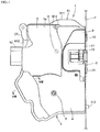
Fig. 1 is a side elevational view showing a door latch device of an embodiment of the present invention, viewed from a vehicle interior side. -
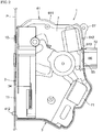
Fig. 2 is a side elevational view showing the door latch device, viewed from a vehicle exterior side. -
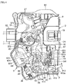
Fig. 3 is a side elevational view showing the door latch device from which a cover is detached, viewed from a vehicle interior side. -
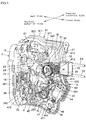
Fig. 4 is a side elevational view showing the door latch device of which a childproof lever is moved to a lock position, viewed from a vehicle interior side. -
Fig. 5 is a perspective view showing the door latch device from which a casing is detached, viewed from an obliquely forward direction in a vehicle exterior side. -
Fig. 6 is a perspective view showing the door latch device which is in a state before attaching covers in the vehicle interior side and a top waterproof cover, viewed from an obliquely rearward direction in a vehicle interior side. -
Fig. 7 is a partially cutaway perspective view showing the door latch device, viewed from an obliquely forward direction. -
Fig. 8 is a rear elevational view showing the door latch device from which a cover member of an engagement unit is detached. -
Fig. 9 is an enlarged exploded perspective view showing a childproof locking mechanism. -
Fig. 10 is an enlarged sectional view taken along the line X-X inFig. 3 . -
Fig. 11 is a side view showing a first switch member, viewed from a vehicle interior side. -
Fig. 12 is a perspective view showing the first switch member, viewed from a vehicle exterior side. -
Fig. 13 is a side view showing a second switch member, viewed from a vehicle interior side. -
Fig. 14 is a side view showing a switch member formed by coupling the first and second switch members, viewed from a vehicle interior side. -
Fig. 15 is an enlarged sectional view taken along the line XV-XV inFig. 14 . -
Fig. 16 is an enlarged sectional view taken along the line XVI-XVI inFig. 14 . -
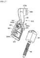
Fig. 17 is a perspective view showing the second switch member in a state before attaching a double locking motor. -
Fig. 18 is an enlarged sectional view taken along the line XVIII-XVIII inFig. 1 . - An embodiment according to the present invention is described with the drawings as follows.
- As shown in
Figs. 1-8 , adoor latch device 1 is provided in a rear end portion of a rear door of a vehicle (not shown). Thedoor latch device 1 comprises anengagement unit 2 for holding the door at a closed position and anoperation unit 3 integrally connected to theengagement unit 2 for operating an engagement mechanism described below of theengagement unit 2. In order to clearly show an internal structure of theactuator unit 3, acover 4 and an auxiliary cover 5 (seeFig. 6 ) respectively covering an inward side of theactuator unit 3 are omitted inFigs. 3 ,4 , and acasing 7 covering an outward side of theactuator unit 3 is omitted inFig. 5 . - As shown in
Figs. 6 ,8 , theengagement unit 2 comprises
a box-like synthetic-resin body 9 having an opening on its rear surface;
a metal cover member 11 (not shown inFig. 8 ) fixed to the rear surface of thebody 9, and fixed to an inner side face of a rear end portion of an inner panel P of the door together with thebody 9 with bolts 10 (seeFig. 1 );
alatch 13 held in an internal space between thebody 9 and thecover member 11 while supported by alatch shaft 12 extending in a longitudinal direction of the vehicle, thelatch 13 having anengagement groove 13a with which a striker S of a vehicle body can engage;
aratchet 15 also held in the internal space between thebody 9 and thecover member 11 while supported by aratchet shaft 14 extending in the longitudinal direction of the vehicle, wherein theratchet 15 prevents thelatch 13 from turning in an opening direction (direction for releasing an engagement with the striker S) by engaging with thelatch 13;
an opening lever 16 (seeFigs. 3 ,5 ) fixed to theratchet shaft 14 in a front face side of thebody 9 and pivoting with theratchet 15; and
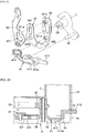
ametal inertia lever 17 held below theratchet 15 in the internal space between thebody 9 and thecover member 11 while pivotally supported by ashaft 33 extending in the longitudinal direction of the vehicle, theshaft 33 also supporting anoutside lever 34 described below. - The engagement mechanism is composed by the
above latch 13 and ratchet 15. - The
inertia lever 17 prevents the door from unexpected opening by keeping the engagement state of thelatch 13 and theratchet 15 even if a crash load affects the door latch device inward by a lateral crash, etc., and acts as follows. - The
inertia lever 17 is formed such that its center of gravity is positioned at a center of theshaft 33, and is perpetually biased clockwise inFig. 8 by aspring 18 of which an end is engaged with aprojection 171 formed on a front face of theinertia lever 17. An outer end portion of the openinglever 16 pivoting with theratchet 15 comes into contact with theprojection 171 at a part opposite to the engagement part of thespring 18. - When an
inside lever 30 and theoutside lever 34 described below are released, the openinglever 16 and theratchet 15 are turned in a releasing direction by anopening link 28 described below. Then, the door can be opened. At this moment, because theinertia lever 17 is turned counterclockwise against thespring 18 by the openinglever 16 as indicated by an arrow inFig. 8 , a door opening operation is not interfered. - Because the
inertia lever 17 is formed such that its center of gravity is positioned at a center of theshaft 33, it does not turn even if a crash load affects the door latch device externally. Therefore, even if theratchet 15 is about to turn in the releasing direction (counterclockwise inFig. 8 ) by an inertia load due to a crash, alower end 15a of theratchet 15 immediately comes into contact with an outerupper end 17a of theinertia lever 17 which is at rest at a fixed position by thespring 18, and thereby blocking the turning in the releasing direction of theratchet 15. Thus, because there is no risk that theratchet 15 is released from thelatch 13 at a moment of a crash, the engagement state between thelatch 13 and theratchet 15 is kept to prevent the door from unexpected opening at a time of a crash, etc. In order to prevent theinertia lever 17 from turning owing to theratchet 15, a contact part between thelower end 15a of theratchet 15 and theupper end 17a of theinertia lever 17 is preferably set on a vertical line passing the center of theshaft 33. - As shown in
Figs. 3-6 , theactuator unit 3 comprises
the above described synthetic-resin casing 7 fixed to thebody 9 of theengagement unit 2;
a locking/unlockingmotor 19 housed in a front upper portion of thecasing 7 such that its rotation shaft is tilted in an oblique front lower direction, wherein themotor 19 bidirectionally rotates by operation of a remote control switch, etc. (not shown);
aworm 20 fixed to the rotation shaft of the locking/unlockingmotor 19;
aworm wheel 22 engaging with theworm 20 and pivotally supported by ashaft 21 extending in a transverse direction of the vehicle;
a locking/unlockinglever 24 pivotally supported by ashaft 23 extending in the transverse direction of the vehicle in thecasing 7 to pivot between an unlock position in which the door opening operation is possible and a lock position in which this operation is impossible;
aknob lever 27 pivotally supported by a shaft 25 (seeFig. 6 ) which is formed on an upper portion of the above describedcover 4 and is extending in an outward direction, wherein theknob lever 27 is connected to a locking knob (not shown) provided on the inner side of the door for manual operation by a motion transmission member D1 such as a Bowden cable, and wherein a lower portion of theknob lever 27 is connected to apin 26 which is formed on an upper end portion of the locking/unlockinglever 24 and is extending in an inward direction;
theopening link 28 pivoting between an unlock position and a lock position in conjunction with the locking/unlockinglever 24
theinside lever 30 of which a lower end portion is pivotally supported by ashaft 29 extending in the transverse direction of the vehicle on thecasing 7, and of which an upper end portion is connected to an inside handle (not shown) provided on the inner side of the door for door opening operation by a motion transmission member D2 such as a Bowden cable;
theoutside lever 34 pivotally supported by a shaft 33 (seeFig. 8 ) in the longitudinal direction of the vehicle on thebody 9, and connected to an outside handle (not shown) provided on the outer side of the door by a rod, etc. (not shown);
achildproof locking mechanism 35 switching between a childproof unlock state in which the release operation of theinside lever 30 actuated by the door opening operation with the inside handle is transmitted to theopening link 28 and theratchet 15 of theengagement unit 2 and a childproof lock state in which this transmission is impossible;
adouble locking mechanism 36 preventing the unlock state due to a wrong operation of the locking knob in the vehicle interior side; and
aswitch member 37 electrically conductive to the locking/unlockingmotor 19 and adouble locking motor 44 described below, etc. - An operation mechanism comprises the locking/unlocking
motor 19, theworm wheel 22, the locking/unlockinglever 24, theknob lever 27, theopening link 28, theinside lever 30, thechildproof locking mechanism 35, and thedouble locking mechanism 36 including adouble locking motor 44 described below, etc. Theknob lever 27 and theinside lever 30 are operation levers. - As shown in
Fig. 6 , aconnection region 4a for connecting the motion transmission members D1, D2 to theknob lever 27 and theinside lever 30 respectively is formed on the vehicle interior side of the front upper portion of the synthetic-resin cover 4. Theknob lever 27 is pivotally supported by theshaft 25 which is formed on theconnection region 4a and is extending in the inward direction, and its lower portion is connected to an end of the motion transmission member D1 in theconnection region 4a. An upper end portion of theinside lever 30 projects to theconnection region 4a through anotch 4b formed on thecover 4. The projected end portion is connected to an end of the motion transmission member D2. As shown inFig. 1 , theconnection region 4a is covered with the above described synthetic-resinauxiliary cover 5 fixed to thecover 4, thereby preventing rainwater from getting into thecasing 7 via theconnection region 4a. - As shown in
Fig. 1 , thecover 4 is fixed to thecasing 7 with upper andlower screws body 9 of theengagement unit 2 is exposed. - As shown in
Figs. 2 ,7 and18 , amotor housing part 71 which is open inward of the vehicle and in which thedouble locking motor 44 described below is housed is integrally molded in the inner side of the front lower portion of the above described synthetic-resin casing 7. - The
worm wheel 22 bidirectionally rotates from a neutral position against a biasing force of thespring 38 depending on a bidirectional rotation of the locking/unlockingmotor 19. When the locking/unlockingmotor 19 stops its rotation, theworm wheel 22 automatically returns to the neutral position from a rotated position by the biasing force of thespring 38. - The locking/unlocking
lever 24 hasteeth 241 engaging withteeth 221 formed at the center portion of theworm wheel 22. When theworm wheel 22 is bidirectionally rotated depending on the rotation of the locking/unlockingmotor 19, the locking/unlockinglever 24 is turned between the unlock position in which the door opening operation by the outside handle and inside handle is possible and the lock position in which this operation is impossible. - The
knob lever 27 pivots between an unlock position and a lock position depending on an unlock operation and a lock operation of the locking knob. When the locking knob is operated to lock, theknob lever 27 is turned counterclockwise at a predetermined angle from the unlock position shown inFig. 3 to the lock position. The locking/unlockinglever 24 connected to theknob lever 27 and theopening link 28 connected to the locking/unlockinglever 24 are respectively turned between the unlock position in which the door opening operation by the outside handle and inside handle is possible and the lock position in which this operation is impossible. - The
inside lever 30 pivots counterclockwise inFig. 3 depending on the opening operation of the inside handle. When the locking/unlockinglever 24 is at the unlock position and thechildproof locking mechanism 35 is in the childproof unlock state, theinside lever 30 turns theopening lever 16 in the releasing direction via a later described releasinglever 39 connected to theinside lever 30 and theopening link 28, and releases the engagement between theratchet 15 and thelatch 13, thereby opening the door. - A substantially L-shaped
fitting hole 301 is formed at the lower portion of theinside lever 30, and an upper connectingshaft 421b formed on an upper portion of a connectinglever 42 described below is fit to thisfitting hole 301. When thechildproof locking mechanism 35 is in the childproof unlock state, the upper connectingshaft 421b fits to a verticallylong hole 301a extending in a vertical direction of an upper portion of thefitting hole 301 so as to move vertically. Therefore, when the door is operated to open, an operation force in a door opening direction of theinside lever 30 is transmitted to a releasinglever 39 described below by the upper connectingshaft 421b. When thechildproof locking mechanism 35 is in the childproof lock state, the upper connectingshaft 421b moves downward to a widebackward hole 301b which is continuing from the verticallylong hole 301a and is extending in a backward direction (opposite direction to the door opening operation direction of the inside lever) in a lower portion of thefitting hole 301. Thus, when the door is operated to open, theinside lever 30 is made to swing idly such that the operation force in the door opening direction of theinside lever 30 is not transmitted to a releasinglever 39 by the upper connectingshaft 421b (described below in detail). - The lower portion of the
opening link 28 is connected to a connectingend part 341 in the vehicle-interior-side of theoutside lever 34 so as to pivot at a predetermined angle in the longitudinal direction of the vehicle, and the upper portion of theopening link 28 is connected to the locking/unlockinglever 24 so as to move in the vertical direction. Theopening link 28 pivots counterclockwise at a predetermined angle from the unlock position shown inFig. 3 to the lock position against a biasing force of a spring (not shown), in the state that it is pivotally supported by the connectingend part 341 of theoutside lever 34 in conjunction with the pivoting of the locking/unlockinglever 24. When theopening link 28 is at the unlock position (shown inFig. 3 ), an upper face of a releasingpart 281 formed at an intermediate portion in the vertical direction of theopening link 28 can come into contact with an under face of the releasedpart 161 of the openinglever 16. - When the door is fully closed, and the locking/unlocking
lever 24 and theopening link 28 are at the unlock position, theopening link 28 is moved upward to turn theopening lever 16 in the releasing direction by releasing theoutside lever 34 depending on an opening operation of the outside handle. Then, the engagement state between theratchet 15 pivoting with the openinglever 16 and thelatch 13 is released, thereby opening the door. - When the door is fully closed, and the locking/unlocking
lever 24 and theopening link 28 are at the lock position, the releasingpart 281 swings idly to the releasedpart 161 of the openinglever 16 even if theopening link 28 moves upward by releasing theoutside lever 34, and therefore the door cannot be opened. - As shown in
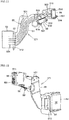
Figs. 9, 10 , thechildproof locking mechanism 35 comprises
the releasinglever 39 of which an intermediate portion is pivotally supported outside theinside lever 30 by theshaft 29 of theinside lever 30, wherein the releasinglever 39 has along hole 391 extending in the vertical direction and formed in a portion upper than theshaft 29;
a synthetic-resinchildproof lever 41 which is housed in a lower end portion rather closer to the rear in thecasing 7, and of which an intermediate portion in the longitudinal direction of the vehicle is pivotally supported by asupport shaft 40 in the transverse direction of the vehicle, wherein thechildproof lever 41 is extending in the longitudinal direction of the vehicle perpendicular to thesupport shaft 40; and
a connectinglever 42 extending in the vertical direction which is provided outside the releasinglever 39 so as to move in the vertical direction, wherein a lower connectingshaft 421a and an upper connectingshaft 421b extending in the inward direction are respectively formed on a lower portion and an upper portion of the connectinglever 42. - An inner side end portion and an outside end portion of the
support shaft 40 are respectively supported on the inner face of thecover 4 and on the inner face of thecasing 7. - A releasing
part 392 extending in the outward direction is integrally formed at the rear end portion of the releasinglever 39, which moves theopening link 28 upward (releasing direction) by coming into contact with the lower end of theopening link 28. - The upper connecting
shaft 421b of the connectinglever 42 passes through thelong hole 391 of the releasinglever 39 so as to slide, and engages with thefitting hole 301 of theinside lever 30. The lower connectingshaft 421a of the connectinglever 42 engages with an arc-shaped connectinghole 411 long in the longitudinal direction of the vehicle so as to slide, wherein the connectinghole 411 is formed at a front end portion of thechildproof lever 41 centered at thesupport shaft 40. - A
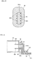
manual operation part 412 is formed at a rear end portion which is an end portion in the longitudinal direction of the vehicle of thechildproof lever 41. Thismanual operation part 412 projects backward while being inserted to the inward end portion of thecover member 11 of theengagement unit 2 below the above describedinertia lever 17. In detail, themanual operation part 412 passes through aguide hole 43 extending in the vertical direction and projects backward from the inner panel P (seeFigs. 1 ,2 ), wherein thisguide hole 43 is formed between a pair of opposite faces which are a vehicle-interior-side side edge of thecover member 11 of the engagement unit and a vehicle-exterior-side side edge of abent portion 4c formed at a rear portion of thecover 4 so as to be bent to thecover member 11 side. A width dimension (dimension in the transverse direction of the vehicle) of theguide hole 43 is equal to or slightly larger than a thickness of the manual operation part 412 (seeFig. 10 ) such that side faces in a thickness direction of themanual operation part 412 respectively come close to or slidably contact with the vehicle-interior-side side edge of thecover member 11 and the vehicle-exterior-side side edge of thebent portion 4c of thecover 4. - According to such a formation, when the
childproof lever 41 is turned in the vertical direction by holding themanual operation part 412, themanual operation part 412 is guided by theguide hole 43, thereby preventing thechildproof lever 41 from vacillating in the transverse direction of the vehicle. When the door is closed, themanual operation part 412 is covered with a part of the vehicle body, which is opposite to the rear surface of thedoor latch device 1. Therefore, themanual operation part 412 can be operated only when the door is open. - An
elastic part 413 is formed on a vehicle-interior-side side face rear than thesupport shaft 40 of thechildproof levers 41, wherein theelastic part 413 is elastically deformable in the transverse direction of the vehicle centered at a front base portion of thechildproof lever 41. Ahemispherical projection 413a projecting inward of the vehicle is formed on a free end portion (rear end portion) of theelastic part 413. On the other hand, a mound-like projection 4d projecting outward is formed on a face of thecover 4 to which theprojection 413a is opposite, wherein an apical surface of theprojection 413a can pass over the mound-like projection 4d by elastically deforming theelastic part 413 in the outward direction. When thechildproof lever 41 is turned from the childproof unlock state (shown inFig. 3 ) to the childproof lock state (shown inFig. 4 ) or is turned reversely, theprojection 413 is moved between an upper side and a lower side while passing over the mound-like projection 4d, and therefore thechildproof lever 41 is stopped to be held at the childproof unlock position or the childproof lock position. - When the
childproof locking mechanism 35 is in the childproof unlock state, that is, thechildproof lever 41 is at the childproof unlock position shown inFig. 3 , as described above, the upper connectingshaft 421b of the connectinglever 42 is fit to the verticallylong hole 301a of thefitting hole 301 of theinside lever 30 while passing through thelong hole 391 of the releasinglever 39. Therefore, when theinside lever 30 is operated in the door opening direction (counterclockwise inFig. 3 ) by the inside handle (not shown), the operation force is transmitted to the releasinglever 39 by the upper connectingshaft 421b, and the releasinglever 39 is turned counterclockwise in conjunction with theinside lever 30. Thus, when the locking/unlockinglever 24 is at the unlock position shown inFig. 3 , the releasingpart 392 of the releasinglever 39 comes into contact with the lower end of theopening link 28 to push up theopening link 28, and turns theopening lever 16 in the releasing direction to release the engagement between thelatch 13 and theratchet 15, thereby opening the door. - On the other hand, when the
childproof locking mechanism 35 is in the childproof lock state, that is, themanual operation part 412 of thechildproof lever 41 is pushed up to turn thechildproof lever 41 to the childproof lock direction (counterclockwise) as shown inFig. 4 , the connectinglever 42 is moved downward by the lower connectingshaft 421a fit to the connectinghole 411 of thechildproof lever 41. Then, the upper connectingshaft 421b moves downward to thebackward hole 301b of thefitting hole 301 of theinside lever 30. Therefore, even if the locking knob (not shown) in the door is unlocked to make the locking/unlockinglever 24 be in the unlock state and theinside lever 30 is turned in the door opening direction, theinside lever 30 swings idly, and thus the operation force of theinside lever 30 is not transmitted to the releasinglever 39 by the upper connectingshaft 421b. Accordingly, because theopening lever 16 cannot be turned in the releasing direction via the releasinglever 39 and theopening link 28 in the childproof lock state, the door cannot be opened by operating theinside lever 30. Even if thechildproof locking mechanism 35 is in the childproof lock state, as far as the locking/unlockinglever 24 is in the unlock state, when the outside handle of the door is operated to turn theoutside lever 34 in the door opening direction, the openinglever 16 can be turned in the releasing direction by theopening link 28, thereby opening the door from the vehicle exterior side. - As shown in
Figs. 3 ,5 ; in downward than the motion transmission members D1, D2 and a later describedfemale connector 52 of theswitch member 37; thedouble locking mechanism 36 comprises
thedouble locking motor 44 rotatable bidirectionally being housed in themotor housing part 71 which is open inward of the vehicle in thecasing 7 such that its rotation axis is tilted,
ahelical gear 45 tilted in an oblique rear lower direction to be rotated by thedouble locking motor 44,
a cylindrical movingmember 46 screwed to thehelical gear 45 to move in an axis direction by rotation of thehelical gear 45, and
adouble locking lever 47 of which a rear lower end portion is pivotally supported by the support shaft 40 (seeFig. 10 ) of the above describedchildproof lever 41 and of which a front end portion substantially U-shaped in a side face view is connected to the movingmember 46. - The
double locking lever 47 is provided outside theopening link 28 such that a part of a vertical directed portion of thedouble locking lever 47 overlaps with a part of the vehicle-exterior-side side face of theopening link 28. A two-forked connectingpart 471 holding the movingmember 46 from backward is formed on a front end portion of thedouble locking lever 47. U-shaped notchedgrooves 472 formed in this connectingpart 471 are fit from backward to a pair of driving pins which are formed on the movingmember 46 so as to project in the transverse direction of the vehicle, thereby connecting thedouble locking lever 47 to the movingmember 46. - In the state that the door is locked, when the
double locking motor 44 is actuated by a portable remote control switch, etc., the movingmember 46 is moved downward according to the rotation of thedouble locking motor 44. Thus, thedouble locking lever 47 pivots around thesupport shaft 40 counterclockwise at a predetermined angle from a double unlock position shown inFigs. 3 ,5 to a double lock position (counterclockwise inFig. 3 , clockwise inFig. 5 ). - When the
double locking lever 47 pivots to the double lock position, a vertical direction block rib 473 (seeFig. 5 ) formed at a part of thedouble locking lever 47 to which theopening link 28 is opposite comes near to and faces a block wall part 283 in aconcavity 282, wherein theconcavity 282 is formed on the vehicle-exterior-side face of theopening link 28 turned to the lock position with the locking/unlockinglever 24, and wherein the block wall part 283 is a front side wall of theconcavity 282, thus a double lock state is formed. When thedouble locking lever 47 pivots to the double lock position, a tip portion of a forward extendingportion 474 formed on an upper end portion of thedouble locking lever 47 comes into contact with aswitch pin 601 of a doublelocking detection switch 60 fixed to asecond switch member 372 described below to press theswitch pin 601. Then, a double locking signal is sent to a control circuit device, etc., and the rotation of thedouble locking motor 44 is stopped. - In the state of the double lock, when the locking knob in a vehicle is operated to unlock, the locking/unlocking
lever 24 connected to theknob lever 27 and theopening link 28 connected to the locking/unlockinglever 24 are about to be turned from the lock position to the unlock position (shown inFig. 3 ). However, because the block wall part 283 of theopening link 28 comes into contact with theblock rib 473 of thedouble locking lever 47 which is at rest at the double lock position, theopening link 28 and the locking/unlockinglever 24 are prevented from turning to the unlock position. Therefore, when it is in the double lock state, the door opening operation by the outside handle of the door is originally blocked, and the shift from the lock state to the unlock state is blocked. - As shown in
Figs. 11-17 , the above describedswitch member 37 comprises afirst switch member 371 electrically conductive to the locking/unlockingmotor 19, etc. and thesecond switch member 372 electrically conductive to thedouble locking motor 44, etc. Thismember 37 is formed by coupling thesecond switch member 372 to thefirst switch member 371. - As shown in
Fig. 11 , thefirst switch member 371 has a shape which can be housed in the upper and front upper portions of thecasing 7. Thismember 371 comprises
a plurality of (five)conductive members 50 electrically conductive to the locking/unlockingmotor 19, a door opening/closing detection switch 55 described below and a locking/unlockingdetection switch 56 described below;
an insert moldedresin member 51 shielding theconductive members 50; and
a synthetic-resin female connector 52 which is integrally molded with a front edge face of theresin member 51 so as to project from thecasing 7 and is open frontward. -
Connection terminals 501 of the respectiveconductive members 50 for the locking/unlockingmotor 19 are exposed from a vehicle-exterior-side side face of theresin member 51 for the purpose of connecting to the locking/unlockingmotor 19 housed in thecasing 7. Moreover,connection terminals 502 of the respectiveconductive members 50 for the door opening/closing detection switch 55 andconnection terminals 503 of the respectiveconductive members 50 for the locking/unlockingdetection switch 56 are respectively exposed inswitch housing parts resin member 51 for the purpose of housing the door opening/closing detection switch 55 and the locking/unlockingdetection switch 56. Theconnection terminals closing detection switch 55 and the locking/unlockingdetection switch 56 in each switchhousing part connection terminals 504 of the respectiveconductive members 50 connected to an external male connector respectively project in thefemale connector 52 so as to follow in a direction (forward) along which the external male connector is connected. Abent portion 513 bent in a thickness direction of theresin member 51, that is, in the outward direction at substantially right angles is on the front end portion of theresin member 51. Thefemale connector 52 is integrally molded with the front face of thisbent portion 513. Agap 53 is formed between a pair of opposite faces of thefemale connector 52 and thebent portion 513, wherein a front lower portion of a topwaterproof cover 61 described below is fit to thisgap 53 from above. - As shown in
Figs. 12 ,15, 16 , a substantially rectangular connectinghole 54 extending vertically is formed on thebent portion 513 and awall part 521 of a base end portion of thefemale connector 52 such that thishole 54 longitudinally passes through thebent portion 513 and a part where theconnection terminals 504 are not inserted on thewall part 521, wherein a connectingpart 372a of an upper portion of thesecond switch member 372 is fit to thishole 54 from backward. Theconnection terminals 504 of the respectiveconductive members 50 project into thefemale connector 52 at a part which is close to the connectinghole 54 and is in the vehicle interior side of the connecting hole 54 (left side inFig. 15 , lower side inFig. 16 ). - As shown in
Fig. 11 , theswitch housing parts resin member 51 of thefirst switch member 371, and the door opening/closing detection switch 55 for detecting a half-latch state of the door is housed in theswitch housing part 511 without loosening while aretractable switch pin 551 is oriented backward. The locking/unlockingdetection switch 56 for detecting the lock/unlock states of the door is housed in theswitch housing part 512 without loosening while aretractable switch pin 561 is extending in an oblique rear lower direction. Each of the door opening/closing detection switch 55 and the locking/unlockingdetection switch 56 is held by a pair of elastic holdingparts switch housing parts - As shown in
Fig. 5 , theswitch pin 551 of the door opening/closing detection switch 55 is pressed by adetection lever 57 which is pivotally supported on thebody 9 of theengagement unit 2 and is turned by contacting with an outer peripheral surface of thelatch 13. That is, the door opening/closing detection switch 55 is in an off state when thelatch 13 pivots to a full-latch position (full close position of door), and is in an on state to inform that the door is in half open or open state by lighting a room lamp, etc. of a vehicle when thelatch 13 pivots to a half-latch position (half open position of door) and an open position respectively. Although it is not shown, it may be possible that a depth dimension of theswitch housing part 511 of thefirst switch member 371 is increased such that two door opening/closing detection switches 55 are housed, and that when any one of the door opening/closing detection switches 55 cannot be operated due to a trouble, etc., the other door opening/closing detection switch 55 is operated to light a room lamp, etc. - The
switch pin 561 of the locking/unlockingdetection switch 56 comes in contact with acam face 242 formed on an upper face of the locking/unlocking lever 24 (seeFigs. 3 ,5 ). When the locking/unlockinglever 24 is shifted between the unlock position (shown inFig. 3 ) and the lock position (clockwise inFig. 3 ) by the locking/unlockingmotor 19 or theknob lever 27, an on/off signal is transmitted to a control circuit, etc. by the locking/unlockingdetection switch 56, and then a lock/unlock state of the door is detected. Moreover, when the locking/unlockinglever 24 is shifted to the unlock position or the lock position by the locking/unlockingmotor 19, the locking/unlockingmotor 19 is automatically stopped at the same time of the activation of the locking/unlockingdetection switch 56. - As shown in
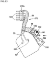
Fig. 13 , thesecond switch member 372 comprises a plurality of (five)conductive members 58, and an insert moldedresin member 59 shielding thesemembers 58. Fiveconductive members 58 are provided to be electrically conductive to thedouble locking motor 44 and the doublelocking detection switch 60, and also to be electrically conductive to a childproof locking detection switch (not shown) when thesecond switch member 372 is shared with another actuator unit comprising a power childproof locking mechanism. - A
wide motor cover 591 is integrally molded with a lower portion of theresin member 59, wherein thiscover 591 has a size for covering thedouble locking motor 44 from the vehicle interior side and sealing an inner side opening of themotor housing part 71 of thecasing 7. Theconnection terminals 581 of the respectiveconductive members 58 for thedouble locking motor 44 project from an upper side of the vehicle-exterior-side side face of the motor cover 591 (seeFig. 17 ).Switch housing parts motor cover 591, wherein thisportion 592 is open outward for housing the doublelocking detection switch 60, and wherein thisportion 593 houses a childproof locking detection switch when thesecond switch member 372 is shared with an actuator unit comprising a power childproof mechanism. - Each of the
switch housing parts elastic holding parts locking detection switch 60 and the childproof locking detection switch respectively, wherein these pairs ofelastic holding parts first switch member 371.Connection terminals 582 of some of theconductive members 58 for the doublelocking detection switch 60 andconnection terminals 582 of the otherconductive members 58 for the childproof locking detection switch (not shown) are exposed in respectiveswitch housing parts - The connecting
part 372a is molded in a frontward direction integrally with a front upper portion of theresin member 59 of thesecond switch member 372, wherein the connectingpart 372a is fit to the connectinghole 54 formed in thefemale connector 52 of thefirst switch member 371 from backward. A plurality of pin-shapedconnection terminals 583 of the respectiveconductive members 58 project frontward from a portion close to the outer side of the connectingpart 372a, wherein theseconnection terminals 583 are connected to an external control circuit device, etc. The connectingpart 372a has a complementary cross-sectional shape with the connectinghole 54 of thefemale connector 52. Hence, when the connectingpart 372a is fit to the connectinghole 54, an outer peripheral surface of the connectingpart 372a comes into surface contact with an inner circumferential surface of the connectinghole 54, and the connectingpart 372a is prevented from coming out from the connectinghole 54 because of their contact frictional force (seeFigs. 15, 16 ). - The connecting
part 372a of thesecond switch member 372 is removably fit to the connectinghole 54 of thefirst switch member 371 in a direction opposite to the female connector 52 (from backward of the female connector 52) to connect thesecond switch member 372 to thefirst switch member 371, and thereby forming the switch member 37 (seeFig. 14 ). - When the
second switch member 372 is coupled with thefirst switch member 371, theconnection terminals 583 of thesecond switch member 372 project in thefemale connector 52 so as to follow the same direction as theconnection terminals 504 of the first switch member 371 (connection direction for an external male connector). Hence, when a wire harness male connector connected to an external control circuit device, etc. is inserted to thefemale connector 52, it is possible to be electrically conductive to both thefirst switch member 371 and thesecond switch member 372 with the singlefemale connector 52. - As shown in
Figs. 5 ,17 ,18 , an assembly sequence of an installation of theswitch member 37 and thedouble locking motor 44 comprises the steps of fitting thedouble locking motor 44 on themotor cover 591 of thesecond switch member 372, fitting theswitch member 37 together with thedouble locking motor 44 on thecasing 7, and screwing thecover 4 to thecasing 7 to shield the inner side opening of thecasing 7 with thecover 4. Thus, the inner side opening of themotor housing part 71 of thecasing 7 is shielded by themotor cover 591. In this occasion, anelongated projection 591a formed on an outside peripheral portion of themotor cover 591 is fit in agroove 72 formed on an opening face of the motor housing part 71 (seeFig. 18 ), thereby preventing rainwater from getting into themotor housing part 71. - Next, the
connection region 4a formed on thecover 4 is covered with theauxiliary cover 5. Thus, as shown inFig. 18 , themotor cover 591 of thesecond switch member 372 and thehelical gear 45 and the vicinity thereof are covered from the vehicle interior side with thecover 4, and theterminal insertion parts 441 side of thedouble locking motor 44 are covered from the vehicle interior side with themotor cover 591 of thesecond switch member 372. Because the wholedouble locking motor 44 including theterminal insertion parts 441 is shielded by themotor housing part 71 of thecasing 7 and themotor cover 591 of thesecond switch member 372, it is possible to increase a waterproof property for the wholedouble locking motor 44 including theterminal insertion parts 441. Furthermore, because a vehicle-interior-side side face of themotor cover 591 of thesecond switch member 372 is covered with thecover 4, the waterproof property for thedouble locking motor 44 is more increased. - Therefore, because there is no risk that rainwater, etc. which has entered from through holes for the motion transmission members D1, D2 of the
casing 7 infiltrates into theterminal insertion parts 441, etc. of thedouble locking motor 44, it is possible to arrange thedouble locking motor 44 below the motion transmission members D1, D2, and it is possible to increase flexibility of design and layout of respective components such as thechildproof locking mechanism 35, thedouble locking mechanism 36, etc. The above assembly sequence of the installation of thedouble locking motor 44 may be carried out reversely: that is, thecover 4, theswitch member 37, fitting of thedouble locking motor 44 to themotor cover 591, and thecasing 7 in this order. - As shown in
Figs. 2 ,6 , the synthetic-resin topwaterproof cover 61 is fit on an upper portion of a connection part of thecover 4 and thecasing 7, thereby preventing rainwater which has entered into the door from getting into thecasing 7 from the upper portion of the connection part. The topwaterproof cover 61 has anupper covering part 611 covering the upper portion of the connection part of thecover 4 and thecasing 7 so as to interpose the upper portion, and a frontside covering part 612 covering the front upper portion of the connection part of thecover 4 and thecasing 7 so as to interpose the upper portion. A two-forkedinsertion part 613 extending downward is formed at a lower end of the frontside covering part 612. Moreover,protrusive parts upper covering part 611 so as to be apart from each other in the longitudinal direction of the vehicle. - When the top
waterproof cover 61 is fit on the upper portion of thecover 4 and thecasing 7, theinsertion part 613 is inserted from above into a peripheral portion of thegap 53 formed between thefemale connector 52 and thebent portion 513 of thefirst switch member 371. Thus, a motion of the topwaterproof cover 61 in the longitudinal direction of the vehicle is restricted. Moreover, when theauxiliary cover 5 is attached, an underface of an oriented outwardbent portion 5a formed at an upper portion of theauxiliary cover 5 comes into contact with an upper face of the frontprotrusive part 614, thereby preventing the topwaterproof cover 61 from being off upward (seeFig. 1 ). - As described above, in the door latch device of the above embodiment; the
childproof lever 41 of thechildproof locking mechanism 35 is pivotally supported by ashaft 40 extending in the transverse direction of the vehicle on thecasing 7, wherein thechildproof lever 41 extends in the longitudinal direction of the vehicle perpendicular to theshaft 40; and thechildproof lever 41 is turned from the childproof unlock position to the childproof lock position or is turned reversely around thesupport shaft 40 by operating themanual operation part 412 projected backward from the rear surface of thecover member 11 of theengagement unit 2. Therefore, it is prevented that a bending load affects thesupport shaft 40 of thechildproof lever 41 as in the past. Accordingly, thechildproof lever 41 can be turned smoothly around thesupport shaft 40, and the wholechildproof locking mechanism 35 including thechildproof lever 41, that is, the connectinglever 42 and the releasinglever 39 that are connected to thechildproof lever 41 can be turned smoothly, too. - Moreover, because the
manual operation part 412 is guided by theguide hole 43 disposed on thecover member 11 so that it can be turned stably in the vertical direction, there is no risk that thechildproof lever 41 bends or vacillates in the transverse direction of the vehicle (thickness direction) around thesupport shaft 40. Therefore, thechildproof lever 41 can be turned more smoothly. - Because the
manual operation part 412 of thechildproof lever 41 is formed to project below thelatch 13, theratchet 15 and theinertia lever 17 which compose the engagement mechanism, that is, thisportion 412 is formed to project backward through a lowest corner part of thecover member 11, it is possible to secure a sufficient space to house thelatch 13, theratchet 15 and theinertia lever 17 in thebody 9, and themanual operation part 412 is not an obstacle for arranging them. - Moreover, holding means stopping and holding the
childproof lever 41 at the childproof unlock/lock positions is composed by theelastic part 413 formed on a vehicle-interior-side side face of thechildproof lever 41 to have theprojection 413a and by the mound-like projection 4d formed on thecover 4 so that thechildproof lever 41 is stopped and held at the childproof unlock/lock positions by making theprojection 413a pass over the mound-like projection 4d to move between an upper side and a lower side. Hence, the formation of the holding means can be simplified. - The foregoing relates to the embodiments of the present invention, but the following various changes and modifications may be added to the present embodiments without departing from the gist of the present invention, which is solely defined by the appended claims.
- In the above embodiment, although the
guide hole 43 for guiding themanual operation part 412 of thechildproof lever 41 is formed between the pair of opposite faces which are the vehicle-interior-side side edge of thecover member 11 and the vehicle-exterior-side side edge of thebent portion 4c formed at the rear portion of thecover 4 so as to be bent to thecover member 11 side, theguide hole 43 may be directly formed on thecover member 11 when thebent portion 4c of thecover 4 is not formed and alternatively thecover member 11 is enlarged. - In the above embodiment, although the
casing 7 and thecover 4 respectively cover the vehicle-interior/exterior-side side faces of theactuator unit 3, alternatively, the cover and the casing respectively may cover the vehicle-interior/exterior-side side faces of theactuator unit 3. Therefore, contrary to the above embodiment, it may be possible that the mound-like projection 4d is formed on thechildproof lever 41 and theelastic part 413 is formed on thecover 4, wherein the mound-like projection 4d is a part of holding means for stopping and holding thechildproof lever 41 at the childproof unlock position and the childproof lock position, and wherein theelastic part 413 has theprojection 413a which can pass over the mound-like projection 4d.
Claims (4)
- A door latch device comprising
an engagement unit (2) which has a box-like body (9) housing an engagement mechanism (13, 15) engaging with a striker of a vehicle body and a cover member (11) covering an opening of the body, the engagement unit (2) being fixed to an inner side of an inner panel (P) of a door;
a casing (7) connected to the engagement unit; and
a childproof locking mechanism (35) housed in the casing (7), which is shifted between a childproof unlock state and a childproof lock state,
wherein in the childproof unlock state, an engagement between the engagement mechanism (13, 15) and the striker (S) is released by transmitting a release operation of an inside lever (30) to the engagement mechanism (13, 15) depending on a door opening operation of an inside handle provided on a vehicle interior side of the door, or by transmitting another release operation of an outside lever (34) to the engagement mechanism (13, 15) depending on a door opening operation of an outside handle provided on an outer side of the door, and
wherein in the childproof lock state, the engagement between the engagement mechanism (13, 15) and the striker (S) is not released by making the former transmission of the release operation of the inside lever (30) impossible, but is released by the latter transmission of said another release operation of the outside lever (34);
wherein the childproof locking mechanism (35) comprises a childproof lever (41) pivotally supported on the casing (7) by a support shaft (40) extending in a transverse direction of a vehicle to shift between the childproof unlock state and the childproof lock state, and
wherein a manual operation part (412) is formed at an end portion of the childproof lever (41) extending in a longitudinal direction of a vehicle perpendicular to the support shaft (40) such that the manual operation part (412) passes through the cover member (11) and projects from this member,
characterized in that a guide hole (43) for guiding and operating the manual operation part (412) is formed on a part of the cover member through which the manual operation part (412) is inserted, and
an inertia lever (17) is provided below the engagement mechanism (13, 15) in the body (9), the inertia lever (17) keeping the engagement state between the engagement mechanism (13, 15) and the striker (S) by pivoting to the engagement mechanism (13, 15) side when a crash load affects the engagement unit, and wherein the manual operation part (412) of the childproof lever (41) is made to project from the cover member (11) below the inertia lever (17). - The door latch device according to claim 1 , wherein in addition to the childproof lever (41), the childproof locking mechanism (35) further comprises
a releasing lever (39) pivotally supported on the casing by a shaft extending in the transverse direction of the vehicle to transmit a release operation of the inside lever (30) to the engagement mechanism (13, 15), and
a connecting lever (42) of which a lower connecting part formed on a lower portion is connected to an end portion of the childproof lever (41) opposite to the manual operation part (412), and of which an upper connecting part formed on an upper portion is inserted into a long hole (391) extending in the vertical direction disposed on the releasing lever (39), and thereby moving in the vertical direction in conjunction with the pivoting of the childproof lever (41), and
wherein the inside lever (30) has a fitting hole (301) to which the upper connecting part inserted to the long hole (391) is fit, the fitting hole (301) having a shape such that when the childproof lever (41) is in the childproof unlock state, a release operation of the inside lever (30) is transmitted to the engagement mechanism (13, 15) via the upper connecting part and the releasing lever (39), and that when the childproof lever (41) is in the childproof lock state, the release operation of the inside lever (30) is not transmitted to the engagement mechanism (13, 15) by making the inside lever (30) swing idly to the upper connecting part and the releasing lever (39). - The door latch device according to claim 1 or 2, wherein a set of holding means stopping and holding the childproof lever (41) at said each state is provided on a pair of opposite faces of the childproof lever (41) and the casing (7).
- The door latch device according to claim 3, wherein the holding means comprises a mound-like projection (4d) formed on any one of the opposite faces of the childproof lever (41) and the casing (7), and an elastic part (413) formed on the other opposite face of them, and wherein the elastic part (413) is elastically deformable in the transverse direction of the vehicle and has a projection passing over the mound-like projection (4d) and stopping when the childproof lever (41) is shifted between the childproof unlock state and the childproof lock state.
Priority Applications (1)
| Application Number | Priority Date | Filing Date | Title |
|---|---|---|---|
| PL15884574T PL3269909T3 (en) | 2015-03-10 | 2015-03-10 | Door latch device |
Applications Claiming Priority (1)
| Application Number | Priority Date | Filing Date | Title |
|---|---|---|---|
| PCT/JP2015/057072 WO2016143082A1 (en) | 2015-03-10 | 2015-03-10 | Door latch device |
Publications (3)
| Publication Number | Publication Date |
|---|---|
| EP3269909A1 EP3269909A1 (en) | 2018-01-17 |
| EP3269909A4 EP3269909A4 (en) | 2018-10-31 |
| EP3269909B1 true EP3269909B1 (en) | 2020-02-26 |
Family
ID=56878878
Family Applications (1)
| Application Number | Title | Priority Date | Filing Date |
|---|---|---|---|
| EP15884574.3A Active EP3269909B1 (en) | 2015-03-10 | 2015-03-10 | Door latch device |
Country Status (5)
| Country | Link |
|---|---|
| US (1) | US10641016B2 (en) |
| EP (1) | EP3269909B1 (en) |
| CN (1) | CN107429525B (en) |
| PL (1) | PL3269909T3 (en) |
| WO (1) | WO2016143082A1 (en) |
Families Citing this family (5)
| Publication number | Priority date | Publication date | Assignee | Title |
|---|---|---|---|---|
| KR102518596B1 (en) * | 2018-01-30 | 2023-04-05 | 현대자동차 주식회사 | Power child lock operating device |
| EP3613928B1 (en) * | 2018-08-17 | 2021-06-09 | Inteva Products, LLC | Inside release spring for vehicle door |
| KR102540933B1 (en) * | 2018-11-20 | 2023-06-08 | 현대자동차주식회사 | Power child lock system for vehicle |
| KR20200105075A (en) * | 2019-02-28 | 2020-09-07 | 현대자동차주식회사 | Power child lock operating device |
| JP7419847B2 (en) | 2020-02-05 | 2024-01-23 | 株式会社アイシン | Vehicle door latch device and its manufacturing method |
Family Cites Families (16)
| Publication number | Priority date | Publication date | Assignee | Title |
|---|---|---|---|---|
| JPS59224782A (en) | 1984-02-16 | 1984-12-17 | 日産自動車株式会社 | Locking apparatus of slide door for car |
| US4969673A (en) * | 1989-10-16 | 1990-11-13 | General Motors Corporation | Door latch with block-out type child safety feature |
| US20020027364A1 (en) * | 1995-09-27 | 2002-03-07 | Trammel Earl M. | Child-key guard unit |
| US6764113B1 (en) * | 1999-09-13 | 2004-07-20 | Atoma International Corp. | Powered vehicle door latch and actuator therefor |
| US20060261602A1 (en) * | 2005-05-20 | 2006-11-23 | Jankowski Krystof P | Inertia catch for door latches |
| JP4422747B2 (en) | 2007-08-07 | 2010-02-24 | 三井金属鉱業株式会社 | Door lock device |
| JP4473919B2 (en) * | 2008-03-31 | 2010-06-02 | 三井金属鉱業株式会社 | Door latch device for automobile |
| US20110133492A1 (en) * | 2009-12-08 | 2011-06-09 | Perkins Donald M | Vehicle door latch |
| JP4953485B2 (en) * | 2010-02-15 | 2012-06-13 | 三井金属アクト株式会社 | Vehicle door latch device |
| JP5170132B2 (en) * | 2010-03-15 | 2013-03-27 | アイシン精機株式会社 | Child lock mechanism |
| GB2480490B (en) * | 2010-05-21 | 2016-06-08 | Inteva Products Usa Llc | Latch assembly |
| DE202010011539U1 (en) * | 2010-08-18 | 2011-12-13 | BROSE SCHLIEßSYSTEME GMBH & CO. KG | Motor vehicle lock |
| US8789861B2 (en) * | 2010-09-03 | 2014-07-29 | Aisin Seiki Kabushiki Kaisha | Vehicle door operating mechanism |
| JP5884766B2 (en) * | 2013-04-24 | 2016-03-15 | 株式会社アンセイ | Vehicle door lock device |
| DE102013012592A1 (en) * | 2013-07-30 | 2015-02-05 | Kiekert Aktiengesellschaft | Motor vehicle door lock |
| WO2016132464A1 (en) * | 2015-02-17 | 2016-08-25 | ジーコム コーポレイション | Automobile door latch apparatus |
-
2015
- 2015-03-10 WO PCT/JP2015/057072 patent/WO2016143082A1/en active Application Filing
- 2015-03-10 EP EP15884574.3A patent/EP3269909B1/en active Active
- 2015-03-10 PL PL15884574T patent/PL3269909T3/en unknown
- 2015-03-10 CN CN201580077543.6A patent/CN107429525B/en active Active
- 2015-03-10 US US15/553,190 patent/US10641016B2/en active Active
Non-Patent Citations (1)
| Title |
|---|
| None * |
Also Published As
| Publication number | Publication date |
|---|---|
| PL3269909T3 (en) | 2020-09-21 |
| US20180112441A1 (en) | 2018-04-26 |
| CN107429525A (en) | 2017-12-01 |
| EP3269909A1 (en) | 2018-01-17 |
| WO2016143082A1 (en) | 2016-09-15 |
| US10641016B2 (en) | 2020-05-05 |
| CN107429525B (en) | 2019-09-03 |
| EP3269909A4 (en) | 2018-10-31 |
Similar Documents
| Publication | Publication Date | Title |
|---|---|---|
| EP3269909B1 (en) | Door latch device | |
| US10907384B2 (en) | Motor vehicle door latch device | |
| CN103527014B (en) | For operating means and the actuator of door lock for vehicle | |
| US8726705B2 (en) | Door opening and closing device for vehicle | |
| JP4524196B2 (en) | Door latch device | |
| US20140175809A1 (en) | Closure mechanism for vehicle door | |
| US7441815B2 (en) | Door lock device | |
| US11035156B2 (en) | Automobile door latch apparatus | |
| US10597909B2 (en) | Vehicle door latch device | |
| EP3296489B1 (en) | Door latch device | |
| US10604969B2 (en) | Vehicle door lock device | |
| JP5050275B2 (en) | Door latch actuator | |
| JP2007100390A (en) | Vehicular door latch device | |
| US10597908B2 (en) | Vehicle door latch device | |
| JP6162946B2 (en) | Door lock device | |
| CN112955621B (en) | Door latch device | |
| JP4496273B2 (en) | Door latch device for automobile | |
| CN112727269A (en) | Door latch device | |
| KR100336468B1 (en) | Double locking device of door for automobile | |
| JP4327677B2 (en) | Door latch device for automobile | |
| JP2017095954A (en) | Vehicular door lock device | |
| CN112969834B (en) | Door latch device | |
| CN112727268A (en) | Door latch device | |
| JP6080518B2 (en) | Door lock device | |
| JP2004156329A (en) | Door latch device for automobile |
Legal Events
| Date | Code | Title | Description |
|---|---|---|---|
| STAA | Information on the status of an ep patent application or granted ep patent |
Free format text: STATUS: THE INTERNATIONAL PUBLICATION HAS BEEN MADE |
|
| PUAI | Public reference made under article 153(3) epc to a published international application that has entered the european phase |
Free format text: ORIGINAL CODE: 0009012 |
|
| STAA | Information on the status of an ep patent application or granted ep patent |
Free format text: STATUS: REQUEST FOR EXAMINATION WAS MADE |
|
| 17P | Request for examination filed |
Effective date: 20171006 |
|
| AK | Designated contracting states |
Kind code of ref document: A1 Designated state(s): AL AT BE BG CH CY CZ DE DK EE ES FI FR GB GR HR HU IE IS IT LI LT LU LV MC MK MT NL NO PL PT RO RS SE SI SK SM TR |
|
| AX | Request for extension of the european patent |
Extension state: BA ME |
|
| DAV | Request for validation of the european patent (deleted) | ||
| DAX | Request for extension of the european patent (deleted) | ||
| A4 | Supplementary search report drawn up and despatched |
Effective date: 20180927 |
|
| RIC1 | Information provided on ipc code assigned before grant |
Ipc: E05B 77/06 20140101ALN20180922BHEP Ipc: E05B 77/26 20140101AFI20180922BHEP Ipc: E05B 79/08 20140101ALI20180922BHEP Ipc: E05B 81/06 20140101ALN20180922BHEP |
|
| RIC1 | Information provided on ipc code assigned before grant |
Ipc: E05B 77/26 20140101AFI20190822BHEP Ipc: E05B 81/06 20140101ALN20190822BHEP Ipc: E05B 77/06 20140101ALN20190822BHEP Ipc: E05B 79/08 20140101ALI20190822BHEP |
|
| RIC1 | Information provided on ipc code assigned before grant |
Ipc: E05B 79/08 20140101ALI20190823BHEP Ipc: E05B 77/06 20140101ALN20190823BHEP Ipc: E05B 81/06 20140101ALN20190823BHEP Ipc: E05B 77/26 20140101AFI20190823BHEP |
|
| GRAP | Despatch of communication of intention to grant a patent |
Free format text: ORIGINAL CODE: EPIDOSNIGR1 |
|
| STAA | Information on the status of an ep patent application or granted ep patent |
Free format text: STATUS: GRANT OF PATENT IS INTENDED |
|
| INTG | Intention to grant announced |
Effective date: 20191010 |
|
| GRAS | Grant fee paid |
Free format text: ORIGINAL CODE: EPIDOSNIGR3 |
|
| GRAJ | Information related to disapproval of communication of intention to grant by the applicant or resumption of examination proceedings by the epo deleted |
Free format text: ORIGINAL CODE: EPIDOSDIGR1 |
|
| GRAL | Information related to payment of fee for publishing/printing deleted |
Free format text: ORIGINAL CODE: EPIDOSDIGR3 |
|
| STAA | Information on the status of an ep patent application or granted ep patent |
Free format text: STATUS: REQUEST FOR EXAMINATION WAS MADE |
|
| GRAR | Information related to intention to grant a patent recorded |
Free format text: ORIGINAL CODE: EPIDOSNIGR71 |
|
| STAA | Information on the status of an ep patent application or granted ep patent |
Free format text: STATUS: GRANT OF PATENT IS INTENDED |
|
| GRAA | (expected) grant |
Free format text: ORIGINAL CODE: 0009210 |
|
| STAA | Information on the status of an ep patent application or granted ep patent |
Free format text: STATUS: THE PATENT HAS BEEN GRANTED |
|
| INTC | Intention to grant announced (deleted) | ||
| AK | Designated contracting states |
Kind code of ref document: B1 Designated state(s): AL AT BE BG CH CY CZ DE DK EE ES FI FR GB GR HR HU IE IS IT LI LT LU LV MC MK MT NL NO PL PT RO RS SE SI SK SM TR |
|
| INTG | Intention to grant announced |
Effective date: 20200120 |
|
| REG | Reference to a national code |
Ref country code: GB Ref legal event code: FG4D |
|
| RIC1 | Information provided on ipc code assigned before grant |
Ipc: E05B 77/26 20140101AFI20200117BHEP Ipc: E05B 77/06 20140101ALN20200117BHEP Ipc: E05B 79/08 20140101ALI20200117BHEP Ipc: E05B 81/06 20140101ALN20200117BHEP |
|
| REG | Reference to a national code |
Ref country code: CH Ref legal event code: EP |
|
| REG | Reference to a national code |
Ref country code: AT Ref legal event code: REF Ref document number: 1237803 Country of ref document: AT Kind code of ref document: T Effective date: 20200315 |
|
| REG | Reference to a national code |
Ref country code: IE Ref legal event code: FG4D |
|
| REG | Reference to a national code |
Ref country code: DE Ref legal event code: R096 Ref document number: 602015047955 Country of ref document: DE |
|
| PG25 | Lapsed in a contracting state [announced via postgrant information from national office to epo] |
Ref country code: NO Free format text: LAPSE BECAUSE OF FAILURE TO SUBMIT A TRANSLATION OF THE DESCRIPTION OR TO PAY THE FEE WITHIN THE PRESCRIBED TIME-LIMIT Effective date: 20200526 Ref country code: RS Free format text: LAPSE BECAUSE OF FAILURE TO SUBMIT A TRANSLATION OF THE DESCRIPTION OR TO PAY THE FEE WITHIN THE PRESCRIBED TIME-LIMIT Effective date: 20200226 Ref country code: FI Free format text: LAPSE BECAUSE OF FAILURE TO SUBMIT A TRANSLATION OF THE DESCRIPTION OR TO PAY THE FEE WITHIN THE PRESCRIBED TIME-LIMIT Effective date: 20200226 |
|
| REG | Reference to a national code |
Ref country code: NL Ref legal event code: MP Effective date: 20200226 |
|
| REG | Reference to a national code |
Ref country code: LT Ref legal event code: MG4D |
|
| PG25 | Lapsed in a contracting state [announced via postgrant information from national office to epo] |
Ref country code: GR Free format text: LAPSE BECAUSE OF FAILURE TO SUBMIT A TRANSLATION OF THE DESCRIPTION OR TO PAY THE FEE WITHIN THE PRESCRIBED TIME-LIMIT Effective date: 20200527 Ref country code: HR Free format text: LAPSE BECAUSE OF FAILURE TO SUBMIT A TRANSLATION OF THE DESCRIPTION OR TO PAY THE FEE WITHIN THE PRESCRIBED TIME-LIMIT Effective date: 20200226 Ref country code: BG Free format text: LAPSE BECAUSE OF FAILURE TO SUBMIT A TRANSLATION OF THE DESCRIPTION OR TO PAY THE FEE WITHIN THE PRESCRIBED TIME-LIMIT Effective date: 20200526 Ref country code: LV Free format text: LAPSE BECAUSE OF FAILURE TO SUBMIT A TRANSLATION OF THE DESCRIPTION OR TO PAY THE FEE WITHIN THE PRESCRIBED TIME-LIMIT Effective date: 20200226 Ref country code: SE Free format text: LAPSE BECAUSE OF FAILURE TO SUBMIT A TRANSLATION OF THE DESCRIPTION OR TO PAY THE FEE WITHIN THE PRESCRIBED TIME-LIMIT Effective date: 20200226 Ref country code: IS Free format text: LAPSE BECAUSE OF FAILURE TO SUBMIT A TRANSLATION OF THE DESCRIPTION OR TO PAY THE FEE WITHIN THE PRESCRIBED TIME-LIMIT Effective date: 20200626 |
|
| PG25 | Lapsed in a contracting state [announced via postgrant information from national office to epo] |
Ref country code: NL Free format text: LAPSE BECAUSE OF FAILURE TO SUBMIT A TRANSLATION OF THE DESCRIPTION OR TO PAY THE FEE WITHIN THE PRESCRIBED TIME-LIMIT Effective date: 20200226 |
|
| REG | Reference to a national code |
Ref country code: DE Ref legal event code: R119 Ref document number: 602015047955 Country of ref document: DE |
|
| PG25 | Lapsed in a contracting state [announced via postgrant information from national office to epo] |
Ref country code: RO Free format text: LAPSE BECAUSE OF FAILURE TO SUBMIT A TRANSLATION OF THE DESCRIPTION OR TO PAY THE FEE WITHIN THE PRESCRIBED TIME-LIMIT Effective date: 20200226 Ref country code: CZ Free format text: LAPSE BECAUSE OF FAILURE TO SUBMIT A TRANSLATION OF THE DESCRIPTION OR TO PAY THE FEE WITHIN THE PRESCRIBED TIME-LIMIT Effective date: 20200226 Ref country code: ES Free format text: LAPSE BECAUSE OF FAILURE TO SUBMIT A TRANSLATION OF THE DESCRIPTION OR TO PAY THE FEE WITHIN THE PRESCRIBED TIME-LIMIT Effective date: 20200226 Ref country code: SK Free format text: LAPSE BECAUSE OF FAILURE TO SUBMIT A TRANSLATION OF THE DESCRIPTION OR TO PAY THE FEE WITHIN THE PRESCRIBED TIME-LIMIT Effective date: 20200226 Ref country code: LT Free format text: LAPSE BECAUSE OF FAILURE TO SUBMIT A TRANSLATION OF THE DESCRIPTION OR TO PAY THE FEE WITHIN THE PRESCRIBED TIME-LIMIT Effective date: 20200226 Ref country code: DK Free format text: LAPSE BECAUSE OF FAILURE TO SUBMIT A TRANSLATION OF THE DESCRIPTION OR TO PAY THE FEE WITHIN THE PRESCRIBED TIME-LIMIT Effective date: 20200226 Ref country code: PT Free format text: LAPSE BECAUSE OF FAILURE TO SUBMIT A TRANSLATION OF THE DESCRIPTION OR TO PAY THE FEE WITHIN THE PRESCRIBED TIME-LIMIT Effective date: 20200719 Ref country code: SM Free format text: LAPSE BECAUSE OF FAILURE TO SUBMIT A TRANSLATION OF THE DESCRIPTION OR TO PAY THE FEE WITHIN THE PRESCRIBED TIME-LIMIT Effective date: 20200226 Ref country code: EE Free format text: LAPSE BECAUSE OF FAILURE TO SUBMIT A TRANSLATION OF THE DESCRIPTION OR TO PAY THE FEE WITHIN THE PRESCRIBED TIME-LIMIT Effective date: 20200226 |
|
| REG | Reference to a national code |
Ref country code: CH Ref legal event code: PL |
|
| REG | Reference to a national code |
Ref country code: AT Ref legal event code: MK05 Ref document number: 1237803 Country of ref document: AT Kind code of ref document: T Effective date: 20200226 |
|
| PG25 | Lapsed in a contracting state [announced via postgrant information from national office to epo] |
Ref country code: MC Free format text: LAPSE BECAUSE OF FAILURE TO SUBMIT A TRANSLATION OF THE DESCRIPTION OR TO PAY THE FEE WITHIN THE PRESCRIBED TIME-LIMIT Effective date: 20200226 |
|
| REG | Reference to a national code |
Ref country code: BE Ref legal event code: MM Effective date: 20200331 |
|
| PG25 | Lapsed in a contracting state [announced via postgrant information from national office to epo] |
Ref country code: LU Free format text: LAPSE BECAUSE OF NON-PAYMENT OF DUE FEES Effective date: 20200310 |
|
| PLBE | No opposition filed within time limit |
Free format text: ORIGINAL CODE: 0009261 |
|
| STAA | Information on the status of an ep patent application or granted ep patent |
Free format text: STATUS: NO OPPOSITION FILED WITHIN TIME LIMIT |
|
| PG25 | Lapsed in a contracting state [announced via postgrant information from national office to epo] |
Ref country code: LI Free format text: LAPSE BECAUSE OF NON-PAYMENT OF DUE FEES Effective date: 20200331 Ref country code: IE Free format text: LAPSE BECAUSE OF NON-PAYMENT OF DUE FEES Effective date: 20200310 Ref country code: CH Free format text: LAPSE BECAUSE OF NON-PAYMENT OF DUE FEES Effective date: 20200331 Ref country code: DE Free format text: LAPSE BECAUSE OF NON-PAYMENT OF DUE FEES Effective date: 20201001 Ref country code: FR Free format text: LAPSE BECAUSE OF NON-PAYMENT OF DUE FEES Effective date: 20200426 Ref country code: AT Free format text: LAPSE BECAUSE OF FAILURE TO SUBMIT A TRANSLATION OF THE DESCRIPTION OR TO PAY THE FEE WITHIN THE PRESCRIBED TIME-LIMIT Effective date: 20200226 |
|
| 26N | No opposition filed |
Effective date: 20201127 |
|
| PG25 | Lapsed in a contracting state [announced via postgrant information from national office to epo] |
Ref country code: SI Free format text: LAPSE BECAUSE OF FAILURE TO SUBMIT A TRANSLATION OF THE DESCRIPTION OR TO PAY THE FEE WITHIN THE PRESCRIBED TIME-LIMIT Effective date: 20200226 Ref country code: BE Free format text: LAPSE BECAUSE OF NON-PAYMENT OF DUE FEES Effective date: 20200331 |
|
| GBPC | Gb: european patent ceased through non-payment of renewal fee |
Effective date: 20200526 |
|
| PG25 | Lapsed in a contracting state [announced via postgrant information from national office to epo] |
Ref country code: GB Free format text: LAPSE BECAUSE OF NON-PAYMENT OF DUE FEES Effective date: 20200526 |
|
| PG25 | Lapsed in a contracting state [announced via postgrant information from national office to epo] |
Ref country code: MT Free format text: LAPSE BECAUSE OF FAILURE TO SUBMIT A TRANSLATION OF THE DESCRIPTION OR TO PAY THE FEE WITHIN THE PRESCRIBED TIME-LIMIT Effective date: 20200226 Ref country code: CY Free format text: LAPSE BECAUSE OF FAILURE TO SUBMIT A TRANSLATION OF THE DESCRIPTION OR TO PAY THE FEE WITHIN THE PRESCRIBED TIME-LIMIT Effective date: 20200226 |
|
| PGFP | Annual fee paid to national office [announced via postgrant information from national office to epo] |
Ref country code: TR Payment date: 20220309 Year of fee payment: 8 Ref country code: PL Payment date: 20220211 Year of fee payment: 8 Ref country code: IT Payment date: 20220210 Year of fee payment: 8 |
|
| PG25 | Lapsed in a contracting state [announced via postgrant information from national office to epo] |
Ref country code: MK Free format text: LAPSE BECAUSE OF FAILURE TO SUBMIT A TRANSLATION OF THE DESCRIPTION OR TO PAY THE FEE WITHIN THE PRESCRIBED TIME-LIMIT Effective date: 20200226 Ref country code: AL Free format text: LAPSE BECAUSE OF FAILURE TO SUBMIT A TRANSLATION OF THE DESCRIPTION OR TO PAY THE FEE WITHIN THE PRESCRIBED TIME-LIMIT Effective date: 20200226 |