EP3269633B1 - Method and system for propeller control - Google Patents
Method and system for propeller control Download PDFInfo
- Publication number
- EP3269633B1 EP3269633B1 EP17180982.5A EP17180982A EP3269633B1 EP 3269633 B1 EP3269633 B1 EP 3269633B1 EP 17180982 A EP17180982 A EP 17180982A EP 3269633 B1 EP3269633 B1 EP 3269633B1
- Authority
- EP
- European Patent Office
- Prior art keywords
- propeller
- engine
- leakage
- flow rate
- oil flow
- Prior art date
- Legal status (The legal status is an assumption and is not a legal conclusion. Google has not performed a legal analysis and makes no representation as to the accuracy of the status listed.)
- Active
Links
Images


Classifications
-
- F—MECHANICAL ENGINEERING; LIGHTING; HEATING; WEAPONS; BLASTING
- F16—ENGINEERING ELEMENTS AND UNITS; GENERAL MEASURES FOR PRODUCING AND MAINTAINING EFFECTIVE FUNCTIONING OF MACHINES OR INSTALLATIONS; THERMAL INSULATION IN GENERAL
- F16N—LUBRICATING
- F16N29/00—Special means in lubricating arrangements or systems providing for the indication or detection of undesired conditions; Use of devices responsive to conditions in lubricating arrangements or systems
- F16N29/02—Special means in lubricating arrangements or systems providing for the indication or detection of undesired conditions; Use of devices responsive to conditions in lubricating arrangements or systems for influencing the supply of lubricant
-
- B—PERFORMING OPERATIONS; TRANSPORTING
- B64—AIRCRAFT; AVIATION; COSMONAUTICS
- B64C—AEROPLANES; HELICOPTERS
- B64C11/00—Propellers, e.g. of ducted type; Features common to propellers and rotors for rotorcraft
- B64C11/30—Blade pitch-changing mechanisms
- B64C11/303—Blade pitch-changing mechanisms characterised by comprising a governor
-
- B—PERFORMING OPERATIONS; TRANSPORTING
- B63—SHIPS OR OTHER WATERBORNE VESSELS; RELATED EQUIPMENT
- B63H—MARINE PROPULSION OR STEERING
- B63H3/00—Propeller-blade pitch changing
- B63H3/06—Propeller-blade pitch changing characterised by use of non-mechanical actuating means, e.g. electrical
- B63H3/08—Propeller-blade pitch changing characterised by use of non-mechanical actuating means, e.g. electrical fluid
-
- B—PERFORMING OPERATIONS; TRANSPORTING
- B64—AIRCRAFT; AVIATION; COSMONAUTICS
- B64C—AEROPLANES; HELICOPTERS
- B64C11/00—Propellers, e.g. of ducted type; Features common to propellers and rotors for rotorcraft
-
- B—PERFORMING OPERATIONS; TRANSPORTING
- B64—AIRCRAFT; AVIATION; COSMONAUTICS
- B64C—AEROPLANES; HELICOPTERS
- B64C11/00—Propellers, e.g. of ducted type; Features common to propellers and rotors for rotorcraft
- B64C11/30—Blade pitch-changing mechanisms
- B64C11/38—Blade pitch-changing mechanisms fluid, e.g. hydraulic
- B64C11/40—Blade pitch-changing mechanisms fluid, e.g. hydraulic automatic
-
- G—PHYSICS
- G01—MEASURING; TESTING
- G01F—MEASURING VOLUME, VOLUME FLOW, MASS FLOW OR LIQUID LEVEL; METERING BY VOLUME
- G01F15/00—Details of, or accessories for, apparatus of groups G01F1/00 - G01F13/00 insofar as such details or appliances are not adapted to particular types of such apparatus
- G01F15/001—Means for regulating or setting the meter for a predetermined quantity
- G01F15/003—Means for regulating or setting the meter for a predetermined quantity using electromagnetic, electric or electronic means
-
- F—MECHANICAL ENGINEERING; LIGHTING; HEATING; WEAPONS; BLASTING
- F16—ENGINEERING ELEMENTS AND UNITS; GENERAL MEASURES FOR PRODUCING AND MAINTAINING EFFECTIVE FUNCTIONING OF MACHINES OR INSTALLATIONS; THERMAL INSULATION IN GENERAL
- F16N—LUBRICATING
- F16N2210/00—Applications
- F16N2210/08—Aircraft
-
- F—MECHANICAL ENGINEERING; LIGHTING; HEATING; WEAPONS; BLASTING
- F16—ENGINEERING ELEMENTS AND UNITS; GENERAL MEASURES FOR PRODUCING AND MAINTAINING EFFECTIVE FUNCTIONING OF MACHINES OR INSTALLATIONS; THERMAL INSULATION IN GENERAL
- F16N—LUBRICATING
- F16N2230/00—Signal processing
-
- F—MECHANICAL ENGINEERING; LIGHTING; HEATING; WEAPONS; BLASTING
- F16—ENGINEERING ELEMENTS AND UNITS; GENERAL MEASURES FOR PRODUCING AND MAINTAINING EFFECTIVE FUNCTIONING OF MACHINES OR INSTALLATIONS; THERMAL INSULATION IN GENERAL
- F16N—LUBRICATING
- F16N2250/00—Measuring
- F16N2250/04—Pressure
-
- F—MECHANICAL ENGINEERING; LIGHTING; HEATING; WEAPONS; BLASTING
- F16—ENGINEERING ELEMENTS AND UNITS; GENERAL MEASURES FOR PRODUCING AND MAINTAINING EFFECTIVE FUNCTIONING OF MACHINES OR INSTALLATIONS; THERMAL INSULATION IN GENERAL
- F16N—LUBRICATING
- F16N2250/00—Measuring
- F16N2250/08—Temperature
-
- F—MECHANICAL ENGINEERING; LIGHTING; HEATING; WEAPONS; BLASTING
- F16—ENGINEERING ELEMENTS AND UNITS; GENERAL MEASURES FOR PRODUCING AND MAINTAINING EFFECTIVE FUNCTIONING OF MACHINES OR INSTALLATIONS; THERMAL INSULATION IN GENERAL
- F16N—LUBRICATING
- F16N2270/00—Controlling
- F16N2270/20—Amount of lubricant
Definitions
- the application relates generally to metering oil delivery to an engine propeller and, more particularly, to compensating for oil leakage when metering oil delivery.
- Aircraft engines are equipped with a propeller governor to sense the speed of the engine and change the propeller blade pitch angle to maintain a desired speed, regardless of the operational conditions of the aircraft.
- a controller modulates an electro-hydraulic servo-valve proportionally to a speed error and oil flow is metered to the propeller through the valve.
- electronic propeller control systems do not account for oil leakage of the propeller shaft. This leads to steady state errors in the propeller speed throughout the operational envelope of the aircraft.
- hydro-mechanical systems that operate with a propeller governor also fail to compensate for oil leakage and thus experience the same problem with steady state errors.
- JP H05 193561 discloses a hydraulic oil compensation system which supplies the hydraulic oil in a discharge line held at a necessary oil pressure level by a sequence valve, into a hydraulic blade angle setting mechanism through a supply valve.
- Modeling and Control of a Controllable Pitch Propeller, by F P M Dullens et al (11 February 2009, "Master's thesis, Technische Universiteit Eindhoven, Department Mechanical Engineering ”) may also be useful in understanding the background of the present disclosure.
- the present invention provides a method for metering oil flow to a propeller of an engine as defined in claim 1.
- determining the leakage flow rate as a function of parameters of the engine comprises estimating the leakage flow rate from a laminar flow model.
- determining the leakage flow rate comprises using engine and propeller environmental parameters and engine geometric parameters to calculate the leakage flow rate.
- the engine and propeller environmental parameters comprise temperature and pressure.
- the engine geometric parameters comprise shaft propeller geometry.
- the method further comprises biasing the leakage flow rate towards a current value of the compensated oil flow request using at least one bias value.
- the at least one bias value is updated when the engine is in a maintenance mode and the propeller is in a steady state, and/or upon at least one of engine start-up and engine reconfiguration, and/or when the engine is set to take-off power.
- the present invention provides a system for metering oil flow to a propeller of an engine as defined in claim 8.
- determining the leakage flow rate as a function of parameters of the engine comprises estimating the leakage flow rate from a laminar flow model.
- determining the leakage flow rate comprises using engine and propeller environmental parameters and engine geometric parameters to calculate the leakage flow rate.
- the engine and propeller environmental parameters comprise temperature and pressure.
- the engine geometric parameters comprise shaft propeller geometry.
- the program instructions are further executable for biasing the leakage flow rate towards a current value of the compensated oil flow request using at least one bias value.
- the at least one bias value is updated when the engine is in a maintenance mode and the propeller is in a steady state, and/or upon at least one of engine start-up and engine reconfiguration, and/or when the engine is set to take-off power.
- An example of a system for metering oil flow to a propeller of an engine comprises means for receiving a requested propeller speed and an actual propeller speed; means for generating an oil flow request based on a difference between the requested propeller speed and the actual propeller speed; means for determining a leakage flow rate as a function of parameters of the engine and the propeller and generating a leakage compensation component; means for combining the leakage compensation component with the oil flow request to obtain a compensated oil flow request; and means for outputting the compensated oil flow request to an oil metering unit of the propeller.
- Fig. 1 illustrates an example aircraft 100 comprising an engine 104 having a propeller 102.
- a propeller control unit 106 is operatively connected to an engine 104.
- the aircraft 100 may be any type of propeller-driven aircraft 100.
- the engine 104 may be any engine 104 having a propeller 102, such as a turboprop engine, a piston engine, a turboshaft engine, and the like.
- the propeller control unit 106 is configured for control and operation of the propeller 102.
- the propeller 102 is a hydromatic propeller, in which a pitch changing mechanism is a mechanical-hydraulic system. Hydraulic forces acting upon a piston are transformed into mechanical forces acting upon the blades of the propeller 102. Piston movement causes rotation, and oil forces act upon the piston.
- a propeller control system 110 is illustratively provided in the propeller control unit 106 for metering oil flow to the propeller 102 via the oil metering unit 108.
- the oil metering unit 108 may be, for example, an electro-hydraulic servo valve (EHSV).
- the propeller control system 110 may be provided externally to the propeller control unit 106 and connected thereto, for example as a stand-alone device or integrated within another device, such as an engine control unit (ECU), an engine electronic controller (EEC), an engine electronic control system, and a Full Authority Digital Engine Controller (FADEC).
- ECU engine control unit
- EEC engine electronic controller
- FADEC Full Authority Digital Engine Controller
- Data may be exchanged between the propeller control system 110 and the propeller control unit 106 on a communication bus composed of various hardware components, such as one or more electrical wires and/or optical fibers, and/or software components. Transmission may take place using at least one communication protocol, such as but not limited to the ARINC Standards.
- FIG 2 is an example embodiment of the propeller control system 110.
- the system 110 receives a requested speed as well as an actual speed for the propeller 102. These may be received from an engine computer (not shown) or an aircraft computer (not shown). In some embodiments, the requested speed is received from an aircraft control, such as a throttle in a cockpit of the aircraft 100. A difference between the requested speed and the actual speed is obtained from an adder 202.
- a proportional speed controller 204 designed for addressing nominal errors primarily due to the power change in the propeller 102- receives the output from the adder 202, which may be referred to as the propeller speed (N p ) error in rotation per minute (RPM).
- N p propeller speed error in rotation per minute
- a proportional gain value K is applied to the N p error by the controller 204, which may be a proportional (P) controller, a proportional integral (PI) controller, or a proportional integral derivative (PID) controller, and an oil flow request is output therefrom.
- P proportional
- PI proportional integral
- PID proportional integral derivative
- the system 110 also comprises a leakage compensator 200, for addressing oil leakage from the propeller shaft.
- the leakage compensator 200 receives as input engine parameters and outputs a leakage compensation component, which is combined with the oil flow request via an adder 206, in order to output a compensated oil flow request.
- the compensated oil flow request is used to meter the oil flow to the propeller 102 through the oil metering unit 108.
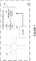
- the leakage compensator 200 comprises a compensation calculator 300.
- the compensation calculator 300 receives engine and/or propeller parameters, such as engine and/or propeller environmental parameters and engine geometric parameters, and outputs the leakage compensation component after having determined a leakage flow rate as a function of the engine and/or propeller parameters.
- the engine/propeller environmental parameters relate to dynamic parameters in the environment of the engine/propeller that vary as the engine operates, such as pressure and temperature.
- the engine environmental parameters may be received as they change, or they may be retrieved by the leakage compensator 200 as needed.
- the engine environmental parameters may be estimated or monitored.
- the engine geometric parameters relate to static parameters representative of engine build. The engine geometric parameters may be determined offline and stored in a memory, for retrieval by the leakage compensator 200 as needed.
- FIG 4 is an example embodiment of the compensation calculator 300.
- a leakage flow rate calculator 402 receives the engine geometry parameters.
- the engine geometry parameters may be specific to the shaft of the propeller 102, for example shaft outside diameter.
- the engine geometry parameters may also relate to other measurements of the engine 104, such as land width, gap width, and the like.
- Pressure data is also received by the leakage flow rate calculator 402.
- a delta pressure representative of a difference between propeller oil pressure and oil discharge pressure is received.
- propeller oil pressure and oil discharge pressure may be received separately and the delta pressure may be computed by the leakage flow rate calculator.
- the leakage flow rate calculator 402 may also consider oil viscosity, as determined by a viscosity calculator 404 on the basis of main oil temperature. Alternatively, oil viscosity is determined outside of the compensation calculator 300 and provided to the leakage flow rate calculator 402 directly.
- the leakage flow rate calculator 402 uses a leakage model based on laminar flow equations to estimate the leakage flow rate.
- the leakage flow rate as output by the leakage flow rate calculator 402 is used as the leakage compensation component and combined with the oil flow request to generate the compensated oil flow request.
- the compensation calculator 300 further uses biasing data, as provided by a biasing module 302, to fine-tune the leakage flow rate as determined by the leakage flow rate calculator 402. This may be done to account for build variations in in the geometry of an engine 104. It may also be used to reduce the number of parameters considered by the leakage flow rate calculator 402 when determining the leakage flow rate. For example, pressure may be removed from the calculation of the leakage flow rate and the bias data may be adjusted to account for a nominal pressure. This may be considered as a trade-off between accuracy for the leakage compensation component and complexity of the system 110.
- the biasing module 302 may provide the biasing data to the compensation calculator 300 upon receipt of a trigger.
- the biasing data may comprise one or more bias values.
- One or more conditions may be used to trigger the biasing module 302.
- the biasing data may be output and/or updated only when the propeller 102 is in steady state. When the propeller 102 is in steady state, there is no movement in the piston of a pitch change mechanism. Therefore, a request for oil flow only feeds a transfer sleeve, allowing transfer sleeve leakage to be determined more explicitly and steady state error to be reduced to a minimum value.
- a specific operating mode of the engine such as a maintenance mode, may be used as a trigger condition.
- an engine and/or aircraft setting may be used as a trigger condition, for example, when the engine is set to take-off power. This allows the leakage compensation component to be fine-tuned in specific engine and/or aircraft operating conditions, such as during take-off, where it may be more critical to avoid steady-state errors in propeller speed.
- the biasing module 302 is triggered to output and/or update the biasing data upon every start of the engine 104, and/or upon a reconfiguration of the engine, i.e. when an active part of the engine/propeller hydraulics is changed. Biasing may be performed upon a manual trigger and/or upon an automatic trigger.
- a bias gain value may be applied to the leakage flow rate using a multiplier 406, and the output of the multiplier 406 may be combined with the bias value via an adder 408 in order to generate the leakage compensation component.
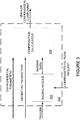
- a method 600 for metering oil flow to the propeller 102 of the engine 104 is illustrated in figure 5 .
- the requested propeller speed and actual propeller speed are received by a processing unit.
- the oil flow request is generated by the processing unit based on the difference between the requested propeller speed and the actual propeller speed, for example using adder 202.
- the leakage flow rate is determined by the processing unit as a function of engine parameters, and the leakage compensation component is generated.
- the leakage compensator 200 uses a leakage model to estimate the leakage flow rate, based on laminar flow equations.
- the engine parameters may be environmental and/or geometric, and may be monitored and/or estimated.
- step 608 comprises biasing the leakage compensation component towards a current value of the compensated oil flow request by providing a bias value to reduce a steady state error of the propeller speed. This may occur by providing a feedback loop from the output of adder 206 to the leakage compensator 200, as illustrated in Figure 2 , and the biasing module 302 outputs bias data for use by the compensation calculator 300 for generating the leakage compensation component.
- the biasing may be triggered upon one or more conditions, such as an engine and/or propeller maintenance mode setting, propeller steady state, engine start-up, engine reconfiguration, and engine/aircraft operating mode.
- the leakage compensation component is combined by the processing unit with the oil flow request, such as by adder 206, and the compensated oil flow request is output, to the oil metering unit 108, as per step 612.
- the leakage compensation component is thus used to adjust the oil flow request output by the controller 204 to prevent steady state error in the propeller speed due to transfer sleeve leakage throughout the operational envelope of the aircraft 100.
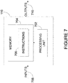
- Figure 7 shows a schematic representation of the propeller control system 110, as a combination of software and hardware components.
- the system 110 may comprise one or more processing units 702 and one or more computer-readable memories 704 storing machine-readable instructions 706 executable by the processing unit 702 and configured to cause the processing unit 702 to generate one or more outputs 710 based on one or more inputs 708.
- the inputs may comprise one or more signals representative of the requested speed, the actual speed, and the engine parameters.
- the outputs 710 may comprise one or more signals representative of the compensated oil flow request.
- Processing unit 702 may comprise any suitable devices configured to cause a series of steps to be performed by system 110 so as to implement a computer-implemented process such that instructions 706, when executed by system 110 or other programmable apparatus, may cause the functions/acts specified in method 600 to be executed.
- Processing unit 702 may comprise, for example, any type of general-purpose microprocessor or microcontroller, a digital signal processing (DSP) processor, an integrated circuit, a field programmable gate array (FPGA), a reconfigurable processor, other suitably programmed or programmable logic circuits, or any combination thereof.
- DSP digital signal processing
- FPGA field programmable gate array
- reconfigurable processor other suitably programmed or programmable logic circuits, or any combination thereof.
- Memory 704 may comprise any suitable known or other machine-readable storage medium.
- Memory 704 may comprise non-transitory computer readable storage medium such as, for example, but not limited to, an electronic, magnetic, optical, electromagnetic, infrared, or semiconductor system, apparatus, or device, or any suitable combination of the foregoing.
- Memory 704 may include a suitable combination of any type of computer memory that is located either internally or externally to system 110 such as, for example, random-access memory (RAM), read-only memory (ROM), compact disc read-only memory (CDROM), electro-optical memory, magneto-optical memory, erasable programmable read-only memory (EPROM), and electrically-erasable programmable read-only memory (EEPROM), Ferroelectric RAM (FRAM) or the like.
- Memory 704 may comprise any storage means (e.g. devices) suitable for retrievably storing machine-readable instructions 706 executable by processing unit 702.
- aspects of the present disclosure may be embodied as systems, devices, methods and/or computer program products. Accordingly, aspects of the present disclosure may take the form of an entirely hardware embodiment, an entirely software embodiment (including firmware, resident software, micro-code, etc.) or an embodiment combining software and hardware aspects. Furthermore, aspects of the present disclosure may take the form of a computer program product embodied in one or more non-transitory computer readable medium(ia) (e.g., memory 704) having computer readable program code (e.g., instructions 706) embodied thereon.
- the computer program product may, for example, be executed by a computer to cause the execution of one or more methods disclosed herein in entirety or in part.
- Computer program code for carrying out operations for aspects of the present disclosure in accordance with instructions 706 may be written in any combination of one or more programming languages, including an object oriented programming language such as Java, Smalltalk, C++ or the like and conventional procedural programming languages, such as the "C" programming language or other programming languages. Such program code may be executed entirely or in part by a computer or other data processing device(s). It is understood that, based on the present disclosure, one skilled in the relevant arts could readily write computer program code for implementing the methods disclosed herein.
Landscapes
- Engineering & Computer Science (AREA)
- Aviation & Aerospace Engineering (AREA)
- Physics & Mathematics (AREA)
- Mechanical Engineering (AREA)
- General Engineering & Computer Science (AREA)
- Chemical & Material Sciences (AREA)
- General Physics & Mathematics (AREA)
- Combustion & Propulsion (AREA)
- Fluid Mechanics (AREA)
- Ocean & Marine Engineering (AREA)
- Electromagnetism (AREA)
- Flow Control (AREA)
- Fluid-Pressure Circuits (AREA)
Priority Applications (1)
| Application Number | Priority Date | Filing Date | Title |
|---|---|---|---|
| PL17180982T PL3269633T3 (pl) | 2016-07-13 | 2017-07-12 | Sposób i system sterowania śmigłem |
Applications Claiming Priority (1)
| Application Number | Priority Date | Filing Date | Title |
|---|---|---|---|
| US15/209,215 US10072796B2 (en) | 2016-07-13 | 2016-07-13 | Metering of oil flow to engine propeller |
Publications (2)
| Publication Number | Publication Date |
|---|---|
| EP3269633A1 EP3269633A1 (en) | 2018-01-17 |
| EP3269633B1 true EP3269633B1 (en) | 2021-12-01 |
Family
ID=59383407
Family Applications (1)
| Application Number | Title | Priority Date | Filing Date |
|---|---|---|---|
| EP17180982.5A Active EP3269633B1 (en) | 2016-07-13 | 2017-07-12 | Method and system for propeller control |
Country Status (4)
| Country | Link |
|---|---|
| US (2) | US10072796B2 (pl) |
| EP (1) | EP3269633B1 (pl) |
| CA (1) | CA2972718A1 (pl) |
| PL (1) | PL3269633T3 (pl) |
Families Citing this family (4)
| Publication number | Priority date | Publication date | Assignee | Title |
|---|---|---|---|---|
| US10604268B2 (en) * | 2017-02-22 | 2020-03-31 | Pratt & Whitney Canada Corp. | Autothrottle control for turboprop engines |
| US11635032B2 (en) * | 2019-12-13 | 2023-04-25 | Pratt & Whitney Canada Corp. | System and method for propeller speed governing |
| US12473843B2 (en) * | 2023-02-13 | 2025-11-18 | Pratt & Whitney Canada Corp. | Hybrid electric propulsion system with pitch change mechanism operation |
| US20250229890A1 (en) | 2024-01-11 | 2025-07-17 | Pratt & Whitney Canada Corp. | Method and system for controlling a variable-pitch propeller with oil leakage compensation |
Family Cites Families (17)
| Publication number | Priority date | Publication date | Assignee | Title |
|---|---|---|---|---|
| US2645293A (en) * | 1946-09-14 | 1953-07-14 | Gen Electric | Apparatus for regulating propulsion power plants |
| US2478752A (en) * | 1948-07-21 | 1949-08-09 | Woodward Governor Co | Condition control apparatus |
| US2640550A (en) * | 1948-07-24 | 1953-06-02 | Curtiss Wright Corp | Turbine propeller control system |
| US2683493A (en) * | 1949-05-04 | 1954-07-13 | Bristol Aeroplane Co Ltd | Valve means for controlling hydraulically operated propeller pitch change mechanism |
| US2957655A (en) * | 1950-06-01 | 1960-10-25 | Curtiss Wright Corp | Turbine propeller control system |
| US2737252A (en) * | 1950-06-01 | 1956-03-06 | Curtiss Wright Corp | Turbine propeller control system |
| US2965179A (en) * | 1959-03-30 | 1960-12-20 | Reggio Ferdinando Carlo | Regulating device |
| US3545881A (en) | 1968-07-24 | 1970-12-08 | Baldwin Lima Hamilton Corp | Controllable pitch propeller with hydraulic power supply and control |
| JP2871209B2 (ja) | 1991-08-06 | 1999-03-17 | トヨタ自動車株式会社 | 可変ピッチプロペラのピッチ制御装置 |
| JPH05193561A (ja) | 1992-01-20 | 1993-08-03 | Mitsubishi Heavy Ind Ltd | 可変ピッチプロペラ翼角制御装置 |
| EP2074025B1 (en) * | 2006-10-11 | 2012-08-29 | Lord Corporation | Aircraft with transient-discriminating propeller balancing system |
| FR2992696B1 (fr) * | 2012-06-28 | 2015-04-10 | Eurocopter France | Distributeur hydraulique, dispositif de reglage du pas de pales, aeronef muni d'un tel distributeur hydraulique |
| US9061760B2 (en) | 2012-08-02 | 2015-06-23 | Bell Helicopter Textron Inc. | Independent blade control system with rotary blade actuator |
| JPWO2014097468A1 (ja) | 2012-12-21 | 2017-01-12 | トヨタ自動車株式会社 | 油圧制御装置 |
| US9267561B2 (en) * | 2013-10-22 | 2016-02-23 | Bell Helicopter Textron Inc. | Rotor brake control system |
| US10233838B2 (en) * | 2014-09-09 | 2019-03-19 | The United States Of America, As Represented By The Secretary Of The Navy | Recuperated gas turbine engine |
| US10501169B2 (en) * | 2016-06-17 | 2019-12-10 | Pratt & Whitney Canada Corp. | Propeller blade angle control system |
-
2016
- 2016-07-13 US US15/209,215 patent/US10072796B2/en active Active
-
2017
- 2017-07-06 CA CA2972718A patent/CA2972718A1/en active Pending
- 2017-07-12 EP EP17180982.5A patent/EP3269633B1/en active Active
- 2017-07-12 PL PL17180982T patent/PL3269633T3/pl unknown
-
2018
- 2018-08-10 US US16/100,768 patent/US10830391B2/en active Active
Also Published As
| Publication number | Publication date |
|---|---|
| US10072796B2 (en) | 2018-09-11 |
| PL3269633T3 (pl) | 2022-02-14 |
| US10830391B2 (en) | 2020-11-10 |
| EP3269633A1 (en) | 2018-01-17 |
| CA2972718A1 (en) | 2018-01-13 |
| US20190003642A1 (en) | 2019-01-03 |
| US20180017209A1 (en) | 2018-01-18 |
Similar Documents
| Publication | Publication Date | Title |
|---|---|---|
| EP3269633B1 (en) | Method and system for propeller control | |
| EP3366590B1 (en) | Autothrottle control for turboprop engines | |
| EP3045982B1 (en) | System and method for controlling a gas turbine engine | |
| US10392099B2 (en) | System and method for aircraft propeller control | |
| US11635032B2 (en) | System and method for propeller speed governing | |
| EP3279450B1 (en) | System and method for an engine controller based on acceleration power | |
| CA2947455A1 (en) | Method and system for improving parameter measurement | |
| EP3244040B1 (en) | Multivariable fuel control and estimator (mfce) for preventing combustor blowout | |
| US10480423B2 (en) | Turbopropeller control system with control saturation management | |
| CA3114231A1 (en) | System and method for detecting and accommodating loss of torque on gas turbine engines | |
| EP3159513B1 (en) | Method and system for calculating a capability of an electronically controlled valve | |
| US11035299B2 (en) | System and method for an engine controller based on inverse dynamics of the engine | |
| US10450966B2 (en) | Device and method for regulating a motor using a thrust measurement | |
| EP4194677A1 (en) | System and method for synthesizing engine output power | |
| RU2574841C1 (ru) | Способ логического управления сложным многосвязным динамическим объектом | |
| EP3193225B1 (en) | Digital communication of power requests between aircraft computer and engine computer | |
| RU2501964C1 (ru) | Система управления газотурбинным двигателем | |
| Xu et al. | Reliability Analysis for Main Engine Control of CFM56-3 Engine | |
| Petunin et al. | Development of requirements for accuracy of inertia compensation in gas temperature control loop of gas turbine engine control systems with a channel selector |
Legal Events
| Date | Code | Title | Description |
|---|---|---|---|
| PUAI | Public reference made under article 153(3) epc to a published international application that has entered the european phase |
Free format text: ORIGINAL CODE: 0009012 |
|
| STAA | Information on the status of an ep patent application or granted ep patent |
Free format text: STATUS: THE APPLICATION HAS BEEN PUBLISHED |
|
| AK | Designated contracting states |
Kind code of ref document: A1 Designated state(s): AL AT BE BG CH CY CZ DE DK EE ES FI FR GB GR HR HU IE IS IT LI LT LU LV MC MK MT NL NO PL PT RO RS SE SI SK SM TR |
|
| AX | Request for extension of the european patent |
Extension state: BA ME |
|
| STAA | Information on the status of an ep patent application or granted ep patent |
Free format text: STATUS: REQUEST FOR EXAMINATION WAS MADE |
|
| 17P | Request for examination filed |
Effective date: 20180711 |
|
| RBV | Designated contracting states (corrected) |
Designated state(s): AL AT BE BG CH CY CZ DE DK EE ES FI FR GB GR HR HU IE IS IT LI LT LU LV MC MK MT NL NO PL PT RO RS SE SI SK SM TR |
|
| GRAP | Despatch of communication of intention to grant a patent |
Free format text: ORIGINAL CODE: EPIDOSNIGR1 |
|
| STAA | Information on the status of an ep patent application or granted ep patent |
Free format text: STATUS: GRANT OF PATENT IS INTENDED |
|
| INTG | Intention to grant announced |
Effective date: 20210618 |
|
| GRAS | Grant fee paid |
Free format text: ORIGINAL CODE: EPIDOSNIGR3 |
|
| GRAA | (expected) grant |
Free format text: ORIGINAL CODE: 0009210 |
|
| STAA | Information on the status of an ep patent application or granted ep patent |
Free format text: STATUS: THE PATENT HAS BEEN GRANTED |
|
| AK | Designated contracting states |
Kind code of ref document: B1 Designated state(s): AL AT BE BG CH CY CZ DE DK EE ES FI FR GB GR HR HU IE IS IT LI LT LU LV MC MK MT NL NO PL PT RO RS SE SI SK SM TR |
|
| REG | Reference to a national code |
Ref country code: GB Ref legal event code: FG4D |
|
| REG | Reference to a national code |
Ref country code: AT Ref legal event code: REF Ref document number: 1451528 Country of ref document: AT Kind code of ref document: T Effective date: 20211215 Ref country code: CH Ref legal event code: EP |
|
| REG | Reference to a national code |
Ref country code: IE Ref legal event code: FG4D |
|
| REG | Reference to a national code |
Ref country code: DE Ref legal event code: R096 Ref document number: 602017050058 Country of ref document: DE |
|
| REG | Reference to a national code |
Ref country code: LT Ref legal event code: MG9D |
|
| REG | Reference to a national code |
Ref country code: NL Ref legal event code: MP Effective date: 20211201 |
|
| REG | Reference to a national code |
Ref country code: AT Ref legal event code: MK05 Ref document number: 1451528 Country of ref document: AT Kind code of ref document: T Effective date: 20211201 |
|
| PG25 | Lapsed in a contracting state [announced via postgrant information from national office to epo] |
Ref country code: RS Free format text: LAPSE BECAUSE OF FAILURE TO SUBMIT A TRANSLATION OF THE DESCRIPTION OR TO PAY THE FEE WITHIN THE PRESCRIBED TIME-LIMIT Effective date: 20211201 Ref country code: LT Free format text: LAPSE BECAUSE OF FAILURE TO SUBMIT A TRANSLATION OF THE DESCRIPTION OR TO PAY THE FEE WITHIN THE PRESCRIBED TIME-LIMIT Effective date: 20211201 Ref country code: FI Free format text: LAPSE BECAUSE OF FAILURE TO SUBMIT A TRANSLATION OF THE DESCRIPTION OR TO PAY THE FEE WITHIN THE PRESCRIBED TIME-LIMIT Effective date: 20211201 Ref country code: BG Free format text: LAPSE BECAUSE OF FAILURE TO SUBMIT A TRANSLATION OF THE DESCRIPTION OR TO PAY THE FEE WITHIN THE PRESCRIBED TIME-LIMIT Effective date: 20220301 Ref country code: AT Free format text: LAPSE BECAUSE OF FAILURE TO SUBMIT A TRANSLATION OF THE DESCRIPTION OR TO PAY THE FEE WITHIN THE PRESCRIBED TIME-LIMIT Effective date: 20211201 |
|
| PG25 | Lapsed in a contracting state [announced via postgrant information from national office to epo] |
Ref country code: SE Free format text: LAPSE BECAUSE OF FAILURE TO SUBMIT A TRANSLATION OF THE DESCRIPTION OR TO PAY THE FEE WITHIN THE PRESCRIBED TIME-LIMIT Effective date: 20211201 Ref country code: NO Free format text: LAPSE BECAUSE OF FAILURE TO SUBMIT A TRANSLATION OF THE DESCRIPTION OR TO PAY THE FEE WITHIN THE PRESCRIBED TIME-LIMIT Effective date: 20220301 Ref country code: LV Free format text: LAPSE BECAUSE OF FAILURE TO SUBMIT A TRANSLATION OF THE DESCRIPTION OR TO PAY THE FEE WITHIN THE PRESCRIBED TIME-LIMIT Effective date: 20211201 Ref country code: HR Free format text: LAPSE BECAUSE OF FAILURE TO SUBMIT A TRANSLATION OF THE DESCRIPTION OR TO PAY THE FEE WITHIN THE PRESCRIBED TIME-LIMIT Effective date: 20211201 Ref country code: GR Free format text: LAPSE BECAUSE OF FAILURE TO SUBMIT A TRANSLATION OF THE DESCRIPTION OR TO PAY THE FEE WITHIN THE PRESCRIBED TIME-LIMIT Effective date: 20220302 Ref country code: ES Free format text: LAPSE BECAUSE OF FAILURE TO SUBMIT A TRANSLATION OF THE DESCRIPTION OR TO PAY THE FEE WITHIN THE PRESCRIBED TIME-LIMIT Effective date: 20211201 |
|
| PG25 | Lapsed in a contracting state [announced via postgrant information from national office to epo] |
Ref country code: NL Free format text: LAPSE BECAUSE OF FAILURE TO SUBMIT A TRANSLATION OF THE DESCRIPTION OR TO PAY THE FEE WITHIN THE PRESCRIBED TIME-LIMIT Effective date: 20211201 |
|
| PG25 | Lapsed in a contracting state [announced via postgrant information from national office to epo] |
Ref country code: SM Free format text: LAPSE BECAUSE OF FAILURE TO SUBMIT A TRANSLATION OF THE DESCRIPTION OR TO PAY THE FEE WITHIN THE PRESCRIBED TIME-LIMIT Effective date: 20211201 Ref country code: SK Free format text: LAPSE BECAUSE OF FAILURE TO SUBMIT A TRANSLATION OF THE DESCRIPTION OR TO PAY THE FEE WITHIN THE PRESCRIBED TIME-LIMIT Effective date: 20211201 Ref country code: RO Free format text: LAPSE BECAUSE OF FAILURE TO SUBMIT A TRANSLATION OF THE DESCRIPTION OR TO PAY THE FEE WITHIN THE PRESCRIBED TIME-LIMIT Effective date: 20211201 Ref country code: PT Free format text: LAPSE BECAUSE OF FAILURE TO SUBMIT A TRANSLATION OF THE DESCRIPTION OR TO PAY THE FEE WITHIN THE PRESCRIBED TIME-LIMIT Effective date: 20220401 Ref country code: EE Free format text: LAPSE BECAUSE OF FAILURE TO SUBMIT A TRANSLATION OF THE DESCRIPTION OR TO PAY THE FEE WITHIN THE PRESCRIBED TIME-LIMIT Effective date: 20211201 |
|
| REG | Reference to a national code |
Ref country code: DE Ref legal event code: R097 Ref document number: 602017050058 Country of ref document: DE |
|
| PG25 | Lapsed in a contracting state [announced via postgrant information from national office to epo] |
Ref country code: IS Free format text: LAPSE BECAUSE OF FAILURE TO SUBMIT A TRANSLATION OF THE DESCRIPTION OR TO PAY THE FEE WITHIN THE PRESCRIBED TIME-LIMIT Effective date: 20220401 |
|
| PLBE | No opposition filed within time limit |
Free format text: ORIGINAL CODE: 0009261 |
|
| STAA | Information on the status of an ep patent application or granted ep patent |
Free format text: STATUS: NO OPPOSITION FILED WITHIN TIME LIMIT |
|
| PG25 | Lapsed in a contracting state [announced via postgrant information from national office to epo] |
Ref country code: DK Free format text: LAPSE BECAUSE OF FAILURE TO SUBMIT A TRANSLATION OF THE DESCRIPTION OR TO PAY THE FEE WITHIN THE PRESCRIBED TIME-LIMIT Effective date: 20211201 Ref country code: AL Free format text: LAPSE BECAUSE OF FAILURE TO SUBMIT A TRANSLATION OF THE DESCRIPTION OR TO PAY THE FEE WITHIN THE PRESCRIBED TIME-LIMIT Effective date: 20211201 |
|
| 26N | No opposition filed |
Effective date: 20220902 |
|
| PG25 | Lapsed in a contracting state [announced via postgrant information from national office to epo] |
Ref country code: SI Free format text: LAPSE BECAUSE OF FAILURE TO SUBMIT A TRANSLATION OF THE DESCRIPTION OR TO PAY THE FEE WITHIN THE PRESCRIBED TIME-LIMIT Effective date: 20211201 |
|
| PG25 | Lapsed in a contracting state [announced via postgrant information from national office to epo] |
Ref country code: MC Free format text: LAPSE BECAUSE OF FAILURE TO SUBMIT A TRANSLATION OF THE DESCRIPTION OR TO PAY THE FEE WITHIN THE PRESCRIBED TIME-LIMIT Effective date: 20211201 |
|
| REG | Reference to a national code |
Ref country code: CH Ref legal event code: PL |
|
| REG | Reference to a national code |
Ref country code: BE Ref legal event code: MM Effective date: 20220731 |
|
| PG25 | Lapsed in a contracting state [announced via postgrant information from national office to epo] |
Ref country code: LU Free format text: LAPSE BECAUSE OF NON-PAYMENT OF DUE FEES Effective date: 20220712 Ref country code: LI Free format text: LAPSE BECAUSE OF NON-PAYMENT OF DUE FEES Effective date: 20220731 Ref country code: CH Free format text: LAPSE BECAUSE OF NON-PAYMENT OF DUE FEES Effective date: 20220731 |
|
| PG25 | Lapsed in a contracting state [announced via postgrant information from national office to epo] |
Ref country code: IT Free format text: LAPSE BECAUSE OF FAILURE TO SUBMIT A TRANSLATION OF THE DESCRIPTION OR TO PAY THE FEE WITHIN THE PRESCRIBED TIME-LIMIT Effective date: 20211201 Ref country code: BE Free format text: LAPSE BECAUSE OF NON-PAYMENT OF DUE FEES Effective date: 20220731 |
|
| P01 | Opt-out of the competence of the unified patent court (upc) registered |
Effective date: 20230530 |
|
| PG25 | Lapsed in a contracting state [announced via postgrant information from national office to epo] |
Ref country code: IE Free format text: LAPSE BECAUSE OF NON-PAYMENT OF DUE FEES Effective date: 20220712 |
|
| PG25 | Lapsed in a contracting state [announced via postgrant information from national office to epo] |
Ref country code: HU Free format text: LAPSE BECAUSE OF FAILURE TO SUBMIT A TRANSLATION OF THE DESCRIPTION OR TO PAY THE FEE WITHIN THE PRESCRIBED TIME-LIMIT; INVALID AB INITIO Effective date: 20170712 |
|
| PG25 | Lapsed in a contracting state [announced via postgrant information from national office to epo] |
Ref country code: MK Free format text: LAPSE BECAUSE OF FAILURE TO SUBMIT A TRANSLATION OF THE DESCRIPTION OR TO PAY THE FEE WITHIN THE PRESCRIBED TIME-LIMIT Effective date: 20211201 Ref country code: CY Free format text: LAPSE BECAUSE OF FAILURE TO SUBMIT A TRANSLATION OF THE DESCRIPTION OR TO PAY THE FEE WITHIN THE PRESCRIBED TIME-LIMIT Effective date: 20211201 |
|
| PG25 | Lapsed in a contracting state [announced via postgrant information from national office to epo] |
Ref country code: MT Free format text: LAPSE BECAUSE OF FAILURE TO SUBMIT A TRANSLATION OF THE DESCRIPTION OR TO PAY THE FEE WITHIN THE PRESCRIBED TIME-LIMIT Effective date: 20211201 |
|
| PGFP | Annual fee paid to national office [announced via postgrant information from national office to epo] |
Ref country code: GB Payment date: 20250619 Year of fee payment: 9 |
|
| PGFP | Annual fee paid to national office [announced via postgrant information from national office to epo] |
Ref country code: FR Payment date: 20250620 Year of fee payment: 9 |
|
| PGFP | Annual fee paid to national office [announced via postgrant information from national office to epo] |
Ref country code: DE Payment date: 20250620 Year of fee payment: 9 |
|
| PGFP | Annual fee paid to national office [announced via postgrant information from national office to epo] |
Ref country code: PL Payment date: 20250701 Year of fee payment: 9 |
|
| PGFP | Annual fee paid to national office [announced via postgrant information from national office to epo] |
Ref country code: CZ Payment date: 20250630 Year of fee payment: 9 |
|
| PG25 | Lapsed in a contracting state [announced via postgrant information from national office to epo] |
Ref country code: TR Free format text: LAPSE BECAUSE OF FAILURE TO SUBMIT A TRANSLATION OF THE DESCRIPTION OR TO PAY THE FEE WITHIN THE PRESCRIBED TIME-LIMIT Effective date: 20211201 |