EP3269316A1 - Treatment instrument - Google Patents
Treatment instrument Download PDFInfo
- Publication number
- EP3269316A1 EP3269316A1 EP15885563.5A EP15885563A EP3269316A1 EP 3269316 A1 EP3269316 A1 EP 3269316A1 EP 15885563 A EP15885563 A EP 15885563A EP 3269316 A1 EP3269316 A1 EP 3269316A1
- Authority
- EP
- European Patent Office
- Prior art keywords
- region
- loop portion
- length
- loop
- pair
- Prior art date
- Legal status (The legal status is an assumption and is not a legal conclusion. Google has not performed a legal analysis and makes no representation as to the accuracy of the status listed.)
- Withdrawn
Links
- 238000005452 bending Methods 0.000 claims abstract description 60
- 208000037062 Polyps Diseases 0.000 description 33
- 230000003902 lesion Effects 0.000 description 7
- 210000001519 tissue Anatomy 0.000 description 5
- 229910003460 diamond Inorganic materials 0.000 description 3
- 239000010432 diamond Substances 0.000 description 3
- 230000000694 effects Effects 0.000 description 2
- 210000000981 epithelium Anatomy 0.000 description 2
- 238000007792 addition Methods 0.000 description 1
- 230000007423 decrease Effects 0.000 description 1
- 238000003780 insertion Methods 0.000 description 1
- 230000037431 insertion Effects 0.000 description 1
- 239000011810 insulating material Substances 0.000 description 1
- 239000000463 material Substances 0.000 description 1
- 238000000034 method Methods 0.000 description 1
- 238000012986 modification Methods 0.000 description 1
- 230000004048 modification Effects 0.000 description 1
- 239000011347 resin Substances 0.000 description 1
- 229920005989 resin Polymers 0.000 description 1
- 230000000630 rising effect Effects 0.000 description 1
- 238000006467 substitution reaction Methods 0.000 description 1
Images


Classifications
-
- A—HUMAN NECESSITIES
- A61—MEDICAL OR VETERINARY SCIENCE; HYGIENE
- A61B—DIAGNOSIS; SURGERY; IDENTIFICATION
- A61B17/00—Surgical instruments, devices or methods
- A61B17/22—Implements for squeezing-off ulcers or the like on inner organs of the body; Implements for scraping-out cavities of body organs, e.g. bones; for invasive removal or destruction of calculus using mechanical vibrations; for removing obstructions in blood vessels, not otherwise provided for
- A61B17/221—Gripping devices in the form of loops or baskets for gripping calculi or similar types of obstructions
-
- A—HUMAN NECESSITIES
- A61—MEDICAL OR VETERINARY SCIENCE; HYGIENE
- A61B—DIAGNOSIS; SURGERY; IDENTIFICATION
- A61B17/00—Surgical instruments, devices or methods
- A61B17/32—Surgical cutting instruments
- A61B17/3205—Excision instruments
- A61B17/32056—Surgical snare instruments
-
- A—HUMAN NECESSITIES
- A61—MEDICAL OR VETERINARY SCIENCE; HYGIENE
- A61B—DIAGNOSIS; SURGERY; IDENTIFICATION
- A61B17/00—Surgical instruments, devices or methods
- A61B17/22—Implements for squeezing-off ulcers or the like on inner organs of the body; Implements for scraping-out cavities of body organs, e.g. bones; for invasive removal or destruction of calculus using mechanical vibrations; for removing obstructions in blood vessels, not otherwise provided for
- A61B17/221—Gripping devices in the form of loops or baskets for gripping calculi or similar types of obstructions
- A61B2017/2212—Gripping devices in the form of loops or baskets for gripping calculi or similar types of obstructions having a closed distal end, e.g. a loop
-
- A—HUMAN NECESSITIES
- A61—MEDICAL OR VETERINARY SCIENCE; HYGIENE
- A61B—DIAGNOSIS; SURGERY; IDENTIFICATION
- A61B18/00—Surgical instruments, devices or methods for transferring non-mechanical forms of energy to or from the body
- A61B2018/00571—Surgical instruments, devices or methods for transferring non-mechanical forms of energy to or from the body for achieving a particular surgical effect
- A61B2018/00601—Cutting
-
- A—HUMAN NECESSITIES
- A61—MEDICAL OR VETERINARY SCIENCE; HYGIENE
- A61B—DIAGNOSIS; SURGERY; IDENTIFICATION
- A61B18/00—Surgical instruments, devices or methods for transferring non-mechanical forms of energy to or from the body
- A61B18/04—Surgical instruments, devices or methods for transferring non-mechanical forms of energy to or from the body by heating
- A61B18/12—Surgical instruments, devices or methods for transferring non-mechanical forms of energy to or from the body by heating by passing a current through the tissue to be heated, e.g. high-frequency current
- A61B18/14—Probes or electrodes therefor
- A61B2018/1405—Electrodes having a specific shape
- A61B2018/1407—Loop
- A61B2018/141—Snare
-
- A—HUMAN NECESSITIES
- A61—MEDICAL OR VETERINARY SCIENCE; HYGIENE
- A61B—DIAGNOSIS; SURGERY; IDENTIFICATION
- A61B18/00—Surgical instruments, devices or methods for transferring non-mechanical forms of energy to or from the body
- A61B18/04—Surgical instruments, devices or methods for transferring non-mechanical forms of energy to or from the body by heating
- A61B18/12—Surgical instruments, devices or methods for transferring non-mechanical forms of energy to or from the body by heating by passing a current through the tissue to be heated, e.g. high-frequency current
- A61B18/14—Probes or electrodes therefor
- A61B2018/1475—Electrodes retractable in or deployable from a housing
Definitions
- the present invention relates to a treatment instrument.
- the snare loop (wire) used for each treatment instrument disclosed in Patent Document 1 to Patent Document 3 has a hexagonal shape which has a first bending portion, a second bending portion, and a third bending portion in the order from a distal end side of the snare loop.
- a proximal end side of the snare loop is tied by a connection pipe and the snare loop is inserted into a sheath so as to be advanced and retracted.
- the length from the third bending portion to the connection pipe is the longest among a length from the first bending portion to the second bending portion, a length from the second bending portion to the third bending portion, and a length from the third bending portion to a connection pipe.
- the snare loop can capture not only a small polyp but also a big polyp. It is possible to restrain operation resistance when the snare loop is pulled into the sheath.
- the present invention is made in view of this problem, and an object thereof is to provide a treatment instrument which can suitably capture a lesion.
- a treatment instrument includes: a sheath which has a longitudinal axis; and a wire which has a loop portion that has a loop shape in a distal end of the wire, that is inserted into the sheath so as to be advanced and retracted, and that has a first bending portion bent to protrude toward an outside of from the loop shape, a pair of second bending portions, and a pair of third bending portions, in an order from the distal end of the wire toward a proximal end of the wire.
- a length of a second region from the pair of second bending portions to the pair of third bending portions is longer than a length of a first region from the first bending portion to the pair of second bending portions and a length of a third region from the pair of third bending portions to the proximal end of the loop portion.
- An angle formed inside the loop portion between the first region and the second region is equal to or smaller than an angle formed on the distal end side of the wire between the first region and the longitudinal axis.
- a length between the pair of second bending portions arranged on both sides of the longitudinal axis is longer than a length between the pair of third bending portions arranged on both sides the longitudinal axis.
- a length of a wire of the third region may be longer than a length of the first region.
- a maximum dimension of a wire of the loop portion in a direction orthogonal to the longitudinal axis in a state where half of a total length of the loop portion in a direction of the longitudinal axis of the loop portion is pulled into the sheath may be 40% to 60% of a maximum dimension of the wire of the loop portion in the orthogonal direction in a state where the whole loop portion protrudes from a distal end of the sheath.
- the third region may be bent to protrude toward an inside of the loop portion.
- the length of the second region is longer than the length of the first region and the length of the third region.
- the angle formed on the distal end side between the first region and the longitudinal axis is equal to or smaller than an angle formed inside the loop portion between the first region and the second region. Therefore, it is possible to suitably capture a lesion.
- FIGS. 1 to 8 A treatment instrument according to a first embodiment of the present invention will be described with reference to FIGS. 1 to 8 .
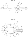
- a treatment instrument 1 As shown in FIG. 1 , a treatment instrument 1 according to the present embodiment includes a sheath 10, a wire 20, and an operation unit 40.
- the sheath 10 has a longitudinal axis L, and is inserted into a body cavity.
- the sheath 10 is configured to include an insulating material, and is formed of, for example, an insulating resin.
- the sheath 10 is formed of a flexible material so as to be advanced and retracted inside a channel of an endoscope having a shape extending along bent luminal tissues inside the body cavity.
- the wire 20 is inserted into the sheath 10 so as to be advanced and retracted. As shown in FIG. 2 , the wire 20 includes a loop portion 21 on a distal end side, and an operation wire 22 on a proximal end side.
- the wire 20 is conductive, and enables a high frequency current to pass through the wire 20.
- the loop portion 21 has a first bending portion 31 which is bent to protrude toward the outside of a loop shape formed by the loop portion 21 itself, a pair of second bending portions 32, and a pair of third bending portions 33 in the order from the distal end side of the wire 20 toward the proximal end side of the wire 20.
- the loop portion 21 has a first region 36 between the first bending portion 31 and the second bending portion 32, a second region 37 between the second bending portion 32 and the third bending portion 33 which are adjacent to each other, and a third region 38 between the third bending portion 33 and a proximal end 21a of the loop portion 21 which are adjacent to each other.
- the loop portion 21 forms a substantially hexagonal loop which is symmetrically formed by interposing the longitudinal axis L.
- loop portion 21 is symmetrically formed by interposing the longitudinal axis L, a shape on one side (upper side in the drawing) will be described.
- a length L2 of the second region 37 is longer than a length L1 of the first region 36 and a length L3 of the third region 38.
- the length L3 of the third region 38 is longer than the length L1 of the first region 36.
- An angle ⁇ formed inside the loop portion 21 between the first region 36 and the second region 37 is smaller than an angle ⁇ formed in the distal end side (outside the loop) between the first region 36 and the longitudinal axis L.
- the angle ⁇ is 100 degrees to 140 degrees.
- the pair of second regions 37 is arranged so as to be parallel to each other.
- the angle ⁇ is smaller than the angle ⁇ , the pair of second regions 37 is in a nonparallel state.
- the loop portion 21 is formed so that a length W1 between the pair of second bending portions 32 arranged on both sides interposing the longitudinal axis L is longer than a length W2 between the pair of third bending portions 33 arranged on both sides interposing the longitudinal axis L.
- the second region 37 is inclined in a direction closer to the longitudinal axis L from the second bending portion 32 toward the third bending portion 33.
- the angle formed between the second region 37 and the third region 38 becomes larger.
- an angle ⁇ formed between a distal end surface 22a of the operation wire 22 and the third region 38 is larger than an angle formed in a case where the pair of second regions 37 is arranged so as to be parallel to each other.
- the operation unit 40 has an operation unit body 41 connected to the proximal end portion of the sheath 10, a slider 42 attached to the operation unit body 41, and a connector 43.
- the operation wire 22 is connected to the slider 42.
- the slider 42 is caused to move forward to and rearward from the operation unit body 41, thereby causing the wire 20 to move forward to and rearward from the sheath 10.
- the loop portion 21 protrudes from the distal end of the sheath 10. If the slider 42 is caused to move rearward from the operation unit body 41, the loop portion 21 is accommodated inside the sheath 10.
- the connector 43 can be connected to a high frequency power supply device (not shown), and can supply a high frequency current to the operation wire 22.
- the operation wire 22 is electrically connected to the loop portion 21. Accordingly, the high frequency current supplied from the high frequency power supply device is transmitted to the loop portion 21 via the operation wire 22.
- an endoscope is inserted into a body cavity by using a known manual skill.
- the distal end of the endoscope is guided to a target area to be treated, thereby capturing the polyp which is the target area within a visible field of the endoscope.
- An operator inserts the treatment instrument 1 into the endoscope, and is caused to protrude from the endoscope. Thereafter, the operator causes the slider 42 of the operation unit 40 shown in FIG. 1 to slide to the distal end side with respect to the operation unit body 41.
- the operation wire 22 connected to the slider 42 is pressed toward the distal end side with respect to the sheath 10 and is moved to the distal end of the sheath 10.
- the whole loop portion 21 protrudes from the distal end of the sheath 10, and the loop portion 21 is deformed by a restoring force using its own elasticity so as to be open in a hexagonal shape (first state).
- a size of the polyp is big (for example, approximately 10 mm)
- the loop portion 21 is fully opened, the operator hangs the loop portion 21 on a polyp P as shown in FIG. 3 .
- the operator causes the slider 42 of the operation unit 40 to slide to the proximal side with respect to the operation unit body 41.
- the proximal end side of the loop portion 21 is pulled into the sheath 10, and a root of the polyp P is bound by the loop portion 21.
- the operator operates the high frequency power supply device so as to supply the high frequency current to the treatment instrument 1.
- the high frequency current is supplied to the loop portion 21.
- the operator excises the polyp P while cauterizing the polyp P bound by the loop portion 21.
- the operator causes the slider 42 of the operation unit 40 to slide to the proximal end side with respect to the operation unit body 41 from a state where the whole loop portion 21 protrudes from the distal end of the sheath 10 as shown in FIG. 1 .
- the operator starts to pull a portion of the third region 38 as shown in FIG. 4 .
- the proximal end side of the loop portion 21 is gradually pulled into the sheath 10.
- the slider 42 is caused to slide to the proximal end side, as shown in FIG. 5 , the third region 38, the third bending portion 33, and a part of the second region 37 are sequentially accommodated inside the sheath 10, thereby causing the loop portion 21 to have a diamond shape (second state).
- a maximum dimension W3 of th loop portion 21 in an orthogonal direction orthogonal to the longitudinal axis L is 40% to 60% of a maximum dimension W4 of the loop portion 21 in the orthogonal direction in the first state.
- the dimension W3 is 60% of the dimension W4.
- the operator brings the loop portion 21 into the second state, and hangs the loop portion 21 on the polyp P. Thereafter, similarly to the above-described case where the size of the polyp is big, the operator supplies the high frequency current to the loop portion 21, and excises the polyp P bound by the loop portion 21.
- a loop portion 50 is formed so that the length of a first region 56 and the length of a third region 58 are longer than the length of a second region 57.
- the loop portion 50 has a shape in which an opening width W5 of the loop portion 50 is shorter than the total length in the direction of the longitudinal axis L of the loop portion 50 compared to the present embodiment.
- an angle ⁇ 1 formed between the first region 56 and the second region 57 becomes larger than the angle P of the loop portion 21. Therefore, when the third region 58 begins to be pulled into the sheath 10, the loop portion 50 rapidly shrinks as shown in FIG. 8 .
- the total length in the direction of the longitudinal axis L of the loop portion 50 with respect to the opening width W5 is longer than the total length in the direction of the longitudinal axis L of the loop portion 21 with respect to the opening width W4 in the present embodiment. Consequently, even when the big polyp is captured, a normal tissue in the vicinity of the polyp also enters the inside of the loop portion 50.
- the third region 58 is pulled into the sheath 10 in order to capture the small polyp, the loop portion 50 collapses, and the size rapidly becomes smaller. Thus, the polyp is less likely to be captured. Therefore, If the small polyp is captured in a state where the whole loop portion 50 protrudes from the sheath 10, a larger amount of the normal tissue in the vicinity also enters the inside of the loop portion 50 compared to the case where the big polyp is captured.
- an angle ⁇ 1 formed between the first region 56 and the second region 57 of the treatment instrument in the related art is set to an angle (angle smaller than the angle ⁇ 1) which is equal to the angle ⁇ formed by the loop portion 21 of the treatment instrument according to the present embodiment
- an angle ⁇ 1 formed between a distal end surface 22a1 of an operation wire 22a and the third region 58 becomes smaller. Accordingly, an opening width W6 of the loop when the third region 58 is pulled into the sheath 10 rapidly becomes smaller compared to the above-described case.
- the length L2 of the second region 37 is longer than both of the length L1 of the first region 36 and the length L3 of the third region 38. Accordingly, the angle ⁇ corresponding to the angle ⁇ 1 of the treatment instrument in the related art is smaller than the angle ⁇ 1. Therefore, the loop portion 21 is not rapidly pulled into the sheath 10, and gradually shrinks, thereby enabling the loop portion 21 to be formed in a diamond shape.
- the dimension W3 when the loop portion 21 is in the second state is 60% of the dimension W4 when the loop portion 21 is in the first state. Accordingly, even if the loop portion 21 is pulled into the sheath 10 until the loop portion 21 is brought into the second state, the loop does not excessively become smaller. In this manner, in a case of the big polyp, the loop portion 21 can be adjusted in the first state and the polyp P is capable of being bound. In a case of the small polyp, the loop portion 21 can be adjusted in the second state and the polyp P is capable of being bound. Therefore, depending on the size of the polyp P, it is possible to properly change the loop size of the loop portion 21.
- the loop portion 21 is not rapidly pulled into the sheath 10. Accordingly, depending on the size of the polyp P, the size of the loop portion 21 can be adjusted by pulling the third region 38 into the sheath 10.
- the loop portion 21 is formed so that the angle ⁇ is larger than the angle ⁇ . That is, the second region 37 is inclined in the direction closer to the longitudinal axis L from the second bending portion 32 toward the third bending portion 33. Accordingly, the angle ⁇ formed between the distal end surface 22a of the operation wire 22 and the third region 38 is large. In this manner, operation resistance is minimized when the operation wire 22 is pulled into the sheath 10. Therefore, the loop portion 21 can be smoothly accommodated inside the sheath 10.
- the length L3 of the third region 38 is longer than the length L1 of the first region 36. Accordingly, compared to a case where the length L3 of the third region 38 is shorter than the length L1 of the first region 36, the angle ⁇ can be minimized. In this manner, since the first region 36 rises from the longitudinal axis L (a rising angle between the first region 36 and the longitudinal axis L formed inside of the loop portion 21 is large), even if the loop portion 21 is pulled into the sheath 10, an advantageous effect is achieved in that the loop portion 21 is less likely to collapse.
- a configuration is adopted in which the high frequency current is caused to flow into the loop portion 21 of the treatment instrument 1.
- a configuration may be adopted in which the high frequency current is not caused to flow into the loop portion 21.
- the angle ⁇ formed on the distal end side (outside the loop) between the first region 36 and the longitudinal axis L is set to be smaller than the angle ⁇ formed inside the loop portion 21 between the first region 36 and the second region 37.
- the angle ⁇ and the angle ⁇ may be equal to each other.
- the length L3 of the third region 38 is set to be longer than the length L1 of the first region 36.
- the length L1 of the first region 36 may be longer than the length L3 of the third region 38.
- FIGS. 9 to 11 A second embodiment according to the present invention will be described with reference to FIGS. 9 to 11 .
- a treatment instrument according to the present embodiment has a configuration of a loop portion which is different from that according to the first embodiment.
- a loop portion 60 includes a pair of second regions 67.
- the loop portion 60 includes a pair of third regions 68.
- the third region 68 is bent to protrude toward the inside of the loop. In this manner, the angle ⁇ formed between the distal end surface 22a of the operation wire 22 and the third region 68 is larger than that when the third region 68 is in a linear state.
- the angle ⁇ formed on the distal end side (outside the loop) between the first region 36 and the longitudinal axis L is equal to the angle ⁇ formed inside the loop portion 60 between the first region 36 and the second region 67. That is, the pair of second regions 67 is arranged so as to be parallel to each other on both sides interposing the longitudinal axis L.
- the third region 68 is bent.
- the loop portion 60 forms a loop having a substantially hexagonal shape which is symmetrically formed by interposing the longitudinal axis L.
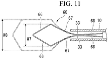
- the slider 42 is caused to slide to the proximal end side, as shown in FIG. 11 , the third region 68, the third bending portion 33, and a portion of the second region 67 are sequentially accommodated inside the sheath 10, thereby causing the loop portion 60 to have a diamond shape (second state).
- the high frequency current is supplied to the loop portion 60, the operator excises the polyp P bound by the loop portion 60.
- a maximum dimension W7 of th loop portion 60 in the orthogonal direction orthogonal to the longitudinal axis L is 40% to 60% of a maximum dimension W8 of the loop portion 60 in the orthogonal direction in the first state, similarly to the first embodiment.
- the angle ⁇ formed between the distal end surface 22a of the operation wire 22 and the third region 68 is larger than that when the third region 68 is in a linear state. Accordingly, operation resistance is minimized when the operation wire 22 is pulled into the sheath 10. Therefore, the loop portion 60 can be smoothly accommodated inside the sheath 10.
- the third region 68 may be bent to protrude toward the inside of the loop.
- the third region 68 may be in a straight state as in the first embodiment, while the pair of the second regions 67 is arranged so as to be parallel to each other.
- the length of the second region is longer than the length of the first region and the length of the third region.
- the angle formed on the distal end side between the first region and the longitudinal axis is equal to or smaller than the angle formed inside the loop portion between the first region and the second region. Therefore, it is possible to suitably capture the lesion.
Landscapes
- Health & Medical Sciences (AREA)
- Life Sciences & Earth Sciences (AREA)
- Surgery (AREA)
- Molecular Biology (AREA)
- Engineering & Computer Science (AREA)
- Biomedical Technology (AREA)
- Heart & Thoracic Surgery (AREA)
- Medical Informatics (AREA)
- Nuclear Medicine, Radiotherapy & Molecular Imaging (AREA)
- Animal Behavior & Ethology (AREA)
- General Health & Medical Sciences (AREA)
- Public Health (AREA)
- Veterinary Medicine (AREA)
- Orthopedic Medicine & Surgery (AREA)
- Vascular Medicine (AREA)
- Surgical Instruments (AREA)
Abstract
Description
- The present invention relates to a treatment instrument.
- Priority is claimed on Japanese Patent Application No.
2015-051290, filed on March 13, 2015 - In the related art, in a medical field, as a treatment instrument in which a treatment unit treating for a living body tissue is arranged in a distal end of an insertion unit to be inserted into a body cavity, for example, a treatment instrument which captures a lesion such as a polyp by a snare loop is disclosed (refer to
Patent Document 1 to Patent Document 3). - The snare loop (wire) used for each treatment instrument disclosed in
Patent Document 1 to Patent Document 3 has a hexagonal shape which has a first bending portion, a second bending portion, and a third bending portion in the order from a distal end side of the snare loop. A proximal end side of the snare loop is tied by a connection pipe and the snare loop is inserted into a sheath so as to be advanced and retracted. - In any snare loop disclosed in
Patent Document 1 to Patent Document 3, the length from the third bending portion to the connection pipe is the longest among a length from the first bending portion to the second bending portion, a length from the second bending portion to the third bending portion, and a length from the third bending portion to a connection pipe. In this manner, the snare loop can capture not only a small polyp but also a big polyp. It is possible to restrain operation resistance when the snare loop is pulled into the sheath. -
- [Patent Document 1] Japanese Unexamined Patent Application, First Publication No.
H11-123198 - [Patent Document 2] Japanese Unexamined Patent Application, First Publication No.
2000-083964 - [Patent Document 3] Japanese Unexamined Patent Application, First Publication No.
H08-71082 - According to each treatment instrument disclosed in
Patent Document 1 to Patent Document 3, when the lesion such as the polyp is captured, areas other than the lesion may enter the inside of the snare loop in some cases as will be mentioned below, - In addition, when a part of the snare loop is pulled into the sheath, it is easy to rapidly change a size of the snare loop in a direction perpendicular to a longitudinal axis of the sheath. Thus, it becomes complicated to adjust the size of the snare loop.
- The present invention is made in view of this problem, and an object thereof is to provide a treatment instrument which can suitably capture a lesion.
- According to a first aspect of the present invention, a treatment instrument includes: a sheath which has a longitudinal axis; and a wire which has a loop portion that has a loop shape in a distal end of the wire, that is inserted into the sheath so as to be advanced and retracted, and that has a first bending portion bent to protrude toward an outside of from the loop shape, a pair of second bending portions, and a pair of third bending portions, in an order from the distal end of the wire toward a proximal end of the wire. In the loop portion, a length of a second region from the pair of second bending portions to the pair of third bending portions is longer than a length of a first region from the first bending portion to the pair of second bending portions and a length of a third region from the pair of third bending portions to the proximal end of the loop portion. An angle formed inside the loop portion between the first region and the second region is equal to or smaller than an angle formed on the distal end side of the wire between the first region and the longitudinal axis.
- According to the treatment instrument in a second aspect of the present invention, in the above-described first aspect, a length between the pair of second bending portions arranged on both sides of the longitudinal axis is longer than a length between the pair of third bending portions arranged on both sides the longitudinal axis.
- According to the treatment instrument in a third aspect of the present invention, in the above-described first aspect, in the loop portion, a length of a wire of the third region may be longer than a length of the first region.
- According to the treatment instrument in a fourth aspect of the present invention, in the above-described first aspect, a maximum dimension of a wire of the loop portion in a direction orthogonal to the longitudinal axis in a state where half of a total length of the loop portion in a direction of the longitudinal axis of the loop portion is pulled into the sheath may be 40% to 60% of a maximum dimension of the wire of the loop portion in the orthogonal direction in a state where the whole loop portion protrudes from a distal end of the sheath.
- According to the treatment instrument in a fifth aspect of the present invention, in the above-described first aspect, the third region may be bent to protrude toward an inside of the loop portion.
- According to the above-described respective aspects, in the loop portion, the length of the second region is longer than the length of the first region and the length of the third region. The angle formed on the distal end side between the first region and the longitudinal axis is equal to or smaller than an angle formed inside the loop portion between the first region and the second region. Therefore, it is possible to suitably capture a lesion.
-
-
FIG. 1 is an overall view of a treatment instrument according to a first embodiment of the present invention. -
FIG. 2 is a view illustrating a loop portion of the treatment instrument inFIG. 1 . -
FIG. 3 is a view for describing an operation of the treatment instrument inFIG. 1 . -
FIG. 4 is a view for describing an operation of the treatment instrument inFIG. 1 . -
FIG. 5 is a view for describing an operation of the treatment instrument inFIG. 1 . -
FIG. 6 is a view for describing an operation of the treatment instrument inFIG. 1 . -
FIG. 7 is a view illustrating a treatment instrument in the related art. -
FIG. 8 is a view illustrating a treatment instrument in the related art. -
FIG. 9 is a view illustrating a loop portion of a treatment instrument according to a second embodiment of the present invention. -
FIG. 10 is a view for describing an operation of the treatment instrument inFIG. 9 . -
FIG. 11 is a view for describing an operation of the treatment instrument inFIG. 9 . - A treatment instrument according to a first embodiment of the present invention will be described with reference to
FIGS. 1 to 8 . - As shown in
FIG. 1 , atreatment instrument 1 according to the present embodiment includes asheath 10, awire 20, and anoperation unit 40. - The
sheath 10 has a longitudinal axis L, and is inserted into a body cavity. In addition, thesheath 10 is configured to include an insulating material, and is formed of, for example, an insulating resin. Thesheath 10 is formed of a flexible material so as to be advanced and retracted inside a channel of an endoscope having a shape extending along bent luminal tissues inside the body cavity. - The
wire 20 is inserted into thesheath 10 so as to be advanced and retracted. As shown inFIG. 2 , thewire 20 includes aloop portion 21 on a distal end side, and anoperation wire 22 on a proximal end side. - The
wire 20 is conductive, and enables a high frequency current to pass through thewire 20. - The
loop portion 21 has afirst bending portion 31 which is bent to protrude toward the outside of a loop shape formed by theloop portion 21 itself, a pair ofsecond bending portions 32, and a pair of third bendingportions 33 in the order from the distal end side of thewire 20 toward the proximal end side of thewire 20. - The
loop portion 21 has afirst region 36 between thefirst bending portion 31 and thesecond bending portion 32, asecond region 37 between thesecond bending portion 32 and thethird bending portion 33 which are adjacent to each other, and athird region 38 between thethird bending portion 33 and aproximal end 21a of theloop portion 21 which are adjacent to each other. - The
loop portion 21 forms a substantially hexagonal loop which is symmetrically formed by interposing the longitudinal axis L. - Hereinafter, since the
loop portion 21 is symmetrically formed by interposing the longitudinal axis L, a shape on one side (upper side in the drawing) will be described. - In the
loop portion 21, a length L2 of thesecond region 37 is longer than a length L1 of thefirst region 36 and a length L3 of thethird region 38. In addition, in theloop portion 21, the length L3 of thethird region 38 is longer than the length L1 of thefirst region 36. - An angle β formed inside the
loop portion 21 between thefirst region 36 and thesecond region 37 is smaller than an angle α formed in the distal end side (outside the loop) between thefirst region 36 and the longitudinal axis L. For example, the angle β is 100 degrees to 140 degrees. In a case where the angle α is equal to the angle β, the pair ofsecond regions 37 is arranged so as to be parallel to each other. However, according to the present embodiment, since the angle β is smaller than the angle α, the pair ofsecond regions 37 is in a nonparallel state. Theloop portion 21 is formed so that a length W1 between the pair ofsecond bending portions 32 arranged on both sides interposing the longitudinal axis L is longer than a length W2 between the pair ofthird bending portions 33 arranged on both sides interposing the longitudinal axis L. In this manner, thesecond region 37 is inclined in a direction closer to the longitudinal axis L from thesecond bending portion 32 toward thethird bending portion 33. As a result, the angle formed between thesecond region 37 and thethird region 38 becomes larger. Accordingly, an angle γ formed between adistal end surface 22a of theoperation wire 22 and thethird region 38 is larger than an angle formed in a case where the pair ofsecond regions 37 is arranged so as to be parallel to each other. - As shown in
FIG. 1 , theoperation unit 40 has anoperation unit body 41 connected to the proximal end portion of thesheath 10, aslider 42 attached to theoperation unit body 41, and aconnector 43. - The
operation wire 22 is connected to theslider 42. In this manner, theslider 42 is caused to move forward to and rearward from theoperation unit body 41, thereby causing thewire 20 to move forward to and rearward from thesheath 10. According to the present embodiment, if theslider 42 is caused to move forward to theoperation unit body 41, theloop portion 21 protrudes from the distal end of thesheath 10. If theslider 42 is caused to move rearward from theoperation unit body 41, theloop portion 21 is accommodated inside thesheath 10. - The
connector 43 can be connected to a high frequency power supply device (not shown), and can supply a high frequency current to theoperation wire 22. Theoperation wire 22 is electrically connected to theloop portion 21. Accordingly, the high frequency current supplied from the high frequency power supply device is transmitted to theloop portion 21 via theoperation wire 22. - Next, an operation of the
treatment instrument 1 according to the present embodiment when excising a polyp bulging from an epithelium of a living body will be described. - First, although not shown, an endoscope is inserted into a body cavity by using a known manual skill. The distal end of the endoscope is guided to a target area to be treated, thereby capturing the polyp which is the target area within a visible field of the endoscope.
- An operator inserts the
treatment instrument 1 into the endoscope, and is caused to protrude from the endoscope. Thereafter, the operator causes theslider 42 of theoperation unit 40 shown inFIG. 1 to slide to the distal end side with respect to theoperation unit body 41. Theoperation wire 22 connected to theslider 42 is pressed toward the distal end side with respect to thesheath 10 and is moved to the distal end of thesheath 10. Thewhole loop portion 21 protrudes from the distal end of thesheath 10, and theloop portion 21 is deformed by a restoring force using its own elasticity so as to be open in a hexagonal shape (first state). In a case where a size of the polyp is big (for example, approximately 10 mm), while theloop portion 21 is fully opened, the operator hangs theloop portion 21 on a polyp P as shown inFIG. 3 . - Subsequently, the operator causes the
slider 42 of theoperation unit 40 to slide to the proximal side with respect to theoperation unit body 41. In this manner, the proximal end side of theloop portion 21 is pulled into thesheath 10, and a root of the polyp P is bound by theloop portion 21. - Next, the operator operates the high frequency power supply device so as to supply the high frequency current to the
treatment instrument 1. The high frequency current is supplied to theloop portion 21. The operator excises the polyp P while cauterizing the polyp P bound by theloop portion 21. - In a case where the size of the polyp is small (for example, approximately 5 mm), , the operator causes the
slider 42 of theoperation unit 40 to slide to the proximal end side with respect to theoperation unit body 41 from a state where thewhole loop portion 21 protrudes from the distal end of thesheath 10 as shown inFIG. 1 . The operator starts to pull a portion of thethird region 38 as shown inFIG. 4 . At this time, the proximal end side of theloop portion 21 is gradually pulled into thesheath 10. Furthermore, if theslider 42 is caused to slide to the proximal end side, as shown inFIG. 5 , thethird region 38, thethird bending portion 33, and a part of thesecond region 37 are sequentially accommodated inside thesheath 10, thereby causing theloop portion 21 to have a diamond shape (second state). - In the second state, particularly in a state where approximately the half of the total length in the direction of the longitudinal axis L of the
loop portion 21 is pulled into thesheath 10, a maximum dimension W3 ofth loop portion 21 in an orthogonal direction orthogonal to the longitudinal axis L is 40% to 60% of a maximum dimension W4 of theloop portion 21 in the orthogonal direction in the first state. According to the present embodiment, the dimension W3 is 60% of the dimension W4. - As shown in
FIG. 6 , the operator brings theloop portion 21 into the second state, and hangs theloop portion 21 on the polyp P. Thereafter, similarly to the above-described case where the size of the polyp is big, the operator supplies the high frequency current to theloop portion 21, and excises the polyp P bound by theloop portion 21. - According to a treatment instrument in the related art, in order to enable an operator to capture not only a small polyp but also a big polyp, as shown in
FIG. 7 , aloop portion 50 is formed so that the length of afirst region 56 and the length of athird region 58 are longer than the length of asecond region 57. In a case where the total length in the direction of the longitudinal axis L of theloop portion 50 is equal to that of theloop portion 21 of thetreatment instrument 1 according to the present embodiment, theloop portion 50 has a shape in which an opening width W5 of theloop portion 50 is shorter than the total length in the direction of the longitudinal axis L of theloop portion 50 compared to the present embodiment. - In addition, due to a relationship among the lengths of the
first region 56, thesecond region 57, and thethird region 58 which are described above, an angle β1 formed between thefirst region 56 and thesecond region 57 becomes larger than the angle P of theloop portion 21. Therefore, when thethird region 58 begins to be pulled into thesheath 10, theloop portion 50 rapidly shrinks as shown inFIG. 8 . - A dimension W6 when a
third bending portion 53 is also accommodated inside the sheath 10 (thethird bending portion 53 and thethird region 58 are accommodated inside the sheath 10) decreases to approximately 30% of the dimension W5 of theloop portion 50 in the orthogonal direction in a state thewhole loop portion 50 shown inFIG. 7 protrudes from the distal end of thesheath 10. - Therefore, according to the treatment instrument in the related art, in a state where the
whole loop portion 50 protrudes from thesheath 10, the total length in the direction of the longitudinal axis L of theloop portion 50 with respect to the opening width W5 is longer than the total length in the direction of the longitudinal axis L of theloop portion 21 with respect to the opening width W4 in the present embodiment. Consequently, even when the big polyp is captured, a normal tissue in the vicinity of the polyp also enters the inside of theloop portion 50. In addition, if thethird region 58 is pulled into thesheath 10 in order to capture the small polyp, theloop portion 50 collapses, and the size rapidly becomes smaller. Thus, the polyp is less likely to be captured. Therefore, If the small polyp is captured in a state where thewhole loop portion 50 protrudes from thesheath 10, a larger amount of the normal tissue in the vicinity also enters the inside of theloop portion 50 compared to the case where the big polyp is captured. - In a case where the angle β1 formed between the
first region 56 and thesecond region 57 of the treatment instrument in the related art is set to an angle (angle smaller than the angle β1) which is equal to the angle β formed by theloop portion 21 of the treatment instrument according to the present embodiment, an angle γ1 formed between a distal end surface 22a1 of anoperation wire 22a and thethird region 58 becomes smaller. Accordingly, an opening width W6 of the loop when thethird region 58 is pulled into thesheath 10 rapidly becomes smaller compared to the above-described case. - According to the
treatment instrument 1 in the present embodiment, the length L2 of thesecond region 37 is longer than both of the length L1 of thefirst region 36 and the length L3 of thethird region 38. Accordingly, the angle β corresponding to the angle β1 of the treatment instrument in the related art is smaller than the angle β1. Therefore, theloop portion 21 is not rapidly pulled into thesheath 10, and gradually shrinks, thereby enabling theloop portion 21 to be formed in a diamond shape. - In addition, the dimension W3 when the
loop portion 21 is in the second state is 60% of the dimension W4 when theloop portion 21 is in the first state. Accordingly, even if theloop portion 21 is pulled into thesheath 10 until theloop portion 21 is brought into the second state, the loop does not excessively become smaller. In this manner, in a case of the big polyp, theloop portion 21 can be adjusted in the first state and the polyp P is capable of being bound. In a case of the small polyp, theloop portion 21 can be adjusted in the second state and the polyp P is capable of being bound. Therefore, depending on the size of the polyp P, it is possible to properly change the loop size of theloop portion 21. - As a result, even if the total length in the direction of the longitudinal axis L of the
loop portion 21 with respect to opening width W4 is not longer than that of theloop portion 50 in the related art, it is possible to suitably capture the polyps P having respectively different sizes. As a result, it is possible to prevent the normal tissue in the vicinity of the polyp P from entering the inside of theloop portion 21. In this manner, it is possible to suitably capture a lesion. - Furthermore, the
loop portion 21 is not rapidly pulled into thesheath 10. Accordingly, depending on the size of the polyp P, the size of theloop portion 21 can be adjusted by pulling thethird region 38 into thesheath 10. - Furthermore, the
loop portion 21 is formed so that the angle α is larger than the angle β. That is, thesecond region 37 is inclined in the direction closer to the longitudinal axis L from thesecond bending portion 32 toward thethird bending portion 33. Accordingly, the angle γ formed between thedistal end surface 22a of theoperation wire 22 and thethird region 38 is large. In this manner, operation resistance is minimized when theoperation wire 22 is pulled into thesheath 10. Therefore, theloop portion 21 can be smoothly accommodated inside thesheath 10. - In addition, the length L3 of the
third region 38 is longer than the length L1 of thefirst region 36. Accordingly, compared to a case where the length L3 of thethird region 38 is shorter than the length L1 of thefirst region 36, the angle α can be minimized. In this manner, since thefirst region 36 rises from the longitudinal axis L (a rising angle between thefirst region 36 and the longitudinal axis L formed inside of theloop portion 21 is large), even if theloop portion 21 is pulled into thesheath 10, an advantageous effect is achieved in that theloop portion 21 is less likely to collapse. - A configuration is adopted in which the high frequency current is caused to flow into the
loop portion 21 of thetreatment instrument 1. However, a configuration may be adopted in which the high frequency current is not caused to flow into theloop portion 21. - The angle α formed on the distal end side (outside the loop) between the
first region 36 and the longitudinal axis L is set to be smaller than the angle β formed inside theloop portion 21 between thefirst region 36 and thesecond region 37. However, the angle α and the angle β may be equal to each other. - The length L3 of the
third region 38 is set to be longer than the length L1 of thefirst region 36. However, the length L1 of thefirst region 36 may be longer than the length L3 of thethird region 38. - A second embodiment according to the present invention will be described with reference to
FIGS. 9 to 11 . - A treatment instrument according to the present embodiment has a configuration of a loop portion which is different from that according to the first embodiment.
- In the following description, the same reference numerals will be given to configuration elements common to those described above, and thus, repeated description will be omitted.
- Instead of the pair of
second regions 37 according to the first embodiment, aloop portion 60 includes a pair ofsecond regions 67. Instead of the pair ofthird regions 38 according to the first embodiment, theloop portion 60 includes a pair ofthird regions 68. - The
third region 68 is bent to protrude toward the inside of the loop. In this manner, the angle γ formed between thedistal end surface 22a of theoperation wire 22 and thethird region 68 is larger than that when thethird region 68 is in a linear state. - In addition, the angle α formed on the distal end side (outside the loop) between the
first region 36 and the longitudinal axis L is equal to the angle β formed inside theloop portion 60 between thefirst region 36 and thesecond region 67. That is, the pair ofsecond regions 67 is arranged so as to be parallel to each other on both sides interposing the longitudinal axis L. - In the
loop portion 60, thethird region 68 is bent. However, theloop portion 60 forms a loop having a substantially hexagonal shape which is symmetrically formed by interposing the longitudinal axis L. - Next, a method will be described in which a polyp bulging from an epithelium of a living body is excised by using the treatment instrument according to the present embodiment. As shown in
FIG. 9 , in a state where thewhole loop portion 60 protrudes from the distal end of the sheath 10 (first state), an operator causes theslider 42 of theoperation unit 40 to slide to the proximal end side with respect to theoperation unit body 41. As shown inFIG. 10 , the operator starts to pull a portion of thethird region 68. At this time, since thethird region 68 is bent to protrude toward the inside of the loop, the proximal end side of theloop portion 60 is gradually pulled into thesheath 10. Furthermore, if theslider 42 is caused to slide to the proximal end side, as shown inFIG. 11 , thethird region 68, thethird bending portion 33, and a portion of thesecond region 67 are sequentially accommodated inside thesheath 10, thereby causing theloop portion 60 to have a diamond shape (second state). Then, similarly to the first embodiment, the high frequency current is supplied to theloop portion 60, the operator excises the polyp P bound by theloop portion 60. - In the second state, particularly in a state where approximately the half of the total length in the direction of the longitudinal axis L of the
loop portion 60 is pulled into thesheath 10, a maximum dimension W7 ofth loop portion 60 in the orthogonal direction orthogonal to the longitudinal axis L is 40% to 60% of a maximum dimension W8 of theloop portion 60 in the orthogonal direction in the first state, similarly to the first embodiment. - According to the treatment instrument in the present embodiment, the angle γ formed between the
distal end surface 22a of theoperation wire 22 and thethird region 68 is larger than that when thethird region 68 is in a linear state. Accordingly, operation resistance is minimized when theoperation wire 22 is pulled into thesheath 10. Therefore, theloop portion 60 can be smoothly accommodated inside thesheath 10. - In a state where the angle α is smaller than the angle β as in the first embodiment, the
third region 68 may be bent to protrude toward the inside of the loop. In addition, thethird region 68 may be in a straight state as in the first embodiment, while the pair of thesecond regions 67 is arranged so as to be parallel to each other. - The preferred embodiments according to the present invention have been described. However, the present invention is not limited to the embodiments. Additions, omissions, substitutions, and modifications of the configurations can be made without departing from the scope of the present invention. Without being limited by the above description, the present invention is limited by the accompanying claims.
- According to the treatment instrument in the above-described respective embodiments, in the loop portion, the length of the second region is longer than the length of the first region and the length of the third region. The angle formed on the distal end side between the first region and the longitudinal axis is equal to or smaller than the angle formed inside the loop portion between the first region and the second region. Therefore, it is possible to suitably capture the lesion.
-
- α
- ANGLE
- β
- ANGLE
- L
- LONGITUDINAL AXIS
- L1
- LENGTH OF FIRST REGION
- L2
- LENGTH OF SECOND REGION
- L3
- LENGTH OF THIRD REGION
- W1
- LENGTH BETWEEN PAIR OF SECOND BENDING PORTIONS
- W2
- LENGTH BETWEEN PAIR OF THIRD BENDING PORTIONS
- 20
- WIRE
- 21, 60
- LOOP PORTION
- 31
- FIRST BENDING PORTION
- 32
- SECOND BENDING PORTION
- 33
- THIRD BENDING PORTION
- 36
- FIRST REGION
- 37, 67
- SECOND REGION
- 38, 68
- THIRD REGION
Claims (5)
- A treatment instrument comprising:a sheath which has a longitudinal axis; anda wire which has a loop portion that has a loop shape in a distal end of the wire, that is inserted into the sheath so as to be advanced and retracted, and that has a first bending portion bent to protrude toward an outside of the loop shape, a pair of second bending portions, and a pair of third bending portions, in an order from the distal end of the wire toward a proximal end of the wire,wherein in the loop portion, a length of a second region from the pair of second bending portions to the pair of third bending portions is longer than a length of a first region from the first bending portion to the pair of second bending portions and a length of a third region from the pair of third bending portions to the proximal end of the loop portion, andwherein an angle formed inside the loop portion between the first region and the second region is equal to or smaller than an angle formed on the distal end side of the wire between the first region and the longitudinal axis.
- The treatment instrument according to claim 1,
wherein a length between the pair of second bending portions arranged on both sides of the longitudinal axis is longer than a length between the pair of third bending portions arranged on both sides the longitudinal axis. - The treatment instrument according to claim 1,
wherein in the loop portion, the length of the third region is longer than the length of the first region. - The treatment instrument according to claim 1,
wherein a maximum dimension of the loop portion in a direction orthogonal to the longitudinal axis in a state where half of a total length of the loop portion in a direction of the longitudinal axis of the loop portion is pulled into the sheath is 40% to 60% of a maximum dimension of the loop portion in the orthogonal direction in a state where the whole loop portion protrudes from a distal end of the sheath. - The treatment instrument according to claim 1,
wherein the third region is bent to protrude toward an inside of the loop portion.
Applications Claiming Priority (2)
| Application Number | Priority Date | Filing Date | Title |
|---|---|---|---|
| JP2015051290 | 2015-03-13 | ||
| PCT/JP2015/081303 WO2016147471A1 (en) | 2015-03-13 | 2015-11-06 | Treatment instrument |
Publications (2)
| Publication Number | Publication Date |
|---|---|
| EP3269316A1 true EP3269316A1 (en) | 2018-01-17 |
| EP3269316A4 EP3269316A4 (en) | 2018-11-21 |
Family
ID=56918768
Family Applications (1)
| Application Number | Title | Priority Date | Filing Date |
|---|---|---|---|
| EP15885563.5A Withdrawn EP3269316A4 (en) | 2015-03-13 | 2015-11-06 | Treatment instrument |
Country Status (5)
| Country | Link |
|---|---|
| US (1) | US10226267B2 (en) |
| EP (1) | EP3269316A4 (en) |
| JP (1) | JP6072384B1 (en) |
| CN (1) | CN107106192B (en) |
| WO (1) | WO2016147471A1 (en) |
Families Citing this family (7)
| Publication number | Priority date | Publication date | Assignee | Title |
|---|---|---|---|---|
| JP6761378B2 (en) | 2017-06-13 | 2020-09-23 | オリンパス株式会社 | Endoscopic treatment tool |
| GB2565113B (en) * | 2017-08-02 | 2022-06-15 | Gyrus Medical Ltd | Electrosurgical instrument |
| CN108175476B (en) * | 2017-12-29 | 2021-01-05 | 杭州安杰思医学科技股份有限公司 | Diameter-variable sleeving and taking device |
| USD903116S1 (en) | 2018-03-12 | 2020-11-24 | Olympus Corporation | Surgical snare |
| RU2695750C1 (en) * | 2019-01-10 | 2019-07-25 | федеральное государственное бюджетное образовательное учреждение высшего образования "Башкирский государственный медицинский университет" Министерства здравоохранения Российской Федерации | Device for removal of stones from extrahepatic bileducts |
| WO2020217383A1 (en) * | 2019-04-25 | 2020-10-29 | オリンパス株式会社 | High-frequency treatment tool |
| JP7832694B2 (en) | 2021-03-04 | 2026-03-18 | カーネリアン メディカル エルエルシー | Snare device |
Family Cites Families (17)
| Publication number | Priority date | Publication date | Assignee | Title |
|---|---|---|---|---|
| DE2132808C3 (en) * | 1971-07-01 | 1981-10-29 | Deyhle, Peter, Dr.med., 8520 Erlangen | Device for the diathermic removal of growths |
| US5059199A (en) * | 1989-04-12 | 1991-10-22 | Olympus Optical Co., Ltd. | Treating device for endoscopes |
| JPH0871082A (en) | 1994-09-08 | 1996-03-19 | Olympus Optical Co Ltd | High frequency incision jig for endoscope |
| JP3983856B2 (en) * | 1997-08-19 | 2007-09-26 | ペンタックス株式会社 | Tip loop type endoscope treatment tool |
| JP4076607B2 (en) | 1997-10-23 | 2008-04-16 | ペンタックス株式会社 | Endoscope snare |
| JP3426510B2 (en) * | 1998-07-27 | 2003-07-14 | ペンタックス株式会社 | High frequency snare for endoscope |
| JP2000083964A (en) | 1998-09-14 | 2000-03-28 | Asahi Optical Co Ltd | Wire loop type treatment tool for endoscope |
| EP1294286B1 (en) * | 2001-01-08 | 2005-12-07 | Boston Scientific Limited | Retrieval basket with releasable tip |
| JP2004249093A (en) * | 2003-01-31 | 2004-09-09 | Olympus Corp | Basket forceps |
| US7270663B2 (en) * | 2003-10-16 | 2007-09-18 | Granit Medical Innovations, Llc | Medical snare loop with indentations for changing effective size of loop and associated method |
| US20070250012A1 (en) * | 2006-04-24 | 2007-10-25 | Ifung Lu | Medical instrument having a medical needle-knife |
| US8858567B2 (en) * | 2006-10-14 | 2014-10-14 | Rafic Saleh | Surgical retrieval device and method |
| US20090024138A1 (en) * | 2007-07-18 | 2009-01-22 | Rafic Saleh | Surgical retrieval device radially deployable from collapsed position to a snare or cauterization loop |
| CN102365058A (en) * | 2009-02-06 | 2012-02-29 | 奥林巴斯医疗株式会社 | handling tools |
| EP2790598B1 (en) * | 2011-12-16 | 2017-04-26 | Stryker Corporation | Embolectomy cage |
| CN202619790U (en) * | 2012-04-11 | 2012-12-26 | 常州市久虹医疗器械有限公司 | Biliary tract stone dislodger with spring soft head |
| CN103654913A (en) * | 2012-09-25 | 2014-03-26 | 常州德天医疗器械有限公司 | Endoscope solid recycling device capable of being temporarily assembled |
-
2015
- 2015-11-06 JP JP2016553040A patent/JP6072384B1/en active Active
- 2015-11-06 WO PCT/JP2015/081303 patent/WO2016147471A1/en not_active Ceased
- 2015-11-06 EP EP15885563.5A patent/EP3269316A4/en not_active Withdrawn
- 2015-11-06 CN CN201580057815.6A patent/CN107106192B/en active Active
-
2017
- 2017-04-26 US US15/497,260 patent/US10226267B2/en active Active
Also Published As
| Publication number | Publication date |
|---|---|
| US20170224365A1 (en) | 2017-08-10 |
| WO2016147471A1 (en) | 2016-09-22 |
| EP3269316A4 (en) | 2018-11-21 |
| JPWO2016147471A1 (en) | 2017-04-27 |
| US10226267B2 (en) | 2019-03-12 |
| JP6072384B1 (en) | 2017-02-01 |
| CN107106192A (en) | 2017-08-29 |
| CN107106192B (en) | 2019-07-23 |
Similar Documents
| Publication | Publication Date | Title |
|---|---|---|
| US10226267B2 (en) | Treatment instrument | |
| JP4471125B2 (en) | High frequency treatment tool | |
| US11096714B2 (en) | Endoscopic treatment tool | |
| EP2394595A1 (en) | Manipulation instrument | |
| EP1997443A3 (en) | Incision tool | |
| US20170000509A1 (en) | Tissue grasping device | |
| EP1842498A1 (en) | Treatment device for endoscope | |
| US11109908B2 (en) | RF surgical resection snare for flexible endoscopy | |
| CN108472053B (en) | Endoscope treatment device | |
| US20200046400A1 (en) | Tissue excision instrument | |
| EP3238641A1 (en) | Medical instrument | |
| JP2003024346A (en) | High frequency incision instrument for endoscope | |
| JP2009095451A (en) | Endoscope treatment tool | |
| JP2002253559A (en) | Wire loop type treatment instrument for endoscope | |
| JP4321853B2 (en) | Endoscopic high-frequency snare | |
| JP4283423B2 (en) | Endoscopic high-frequency snare | |
| JP2007301285A (en) | High-frequency treatment instrument | |
| WO2011157824A1 (en) | Surgical instrument | |
| US7530983B1 (en) | Surgical device for removing polyps | |
| JP2007054584A (en) | Endoscope snare | |
| JP4320194B2 (en) | Endoscopic high frequency knife | |
| JP4589511B2 (en) | Endoscopic high frequency snare | |
| KR101188132B1 (en) | Knife for internal treatment | |
| KR20160035930A (en) | Endoscopic snare device | |
| JP4761597B2 (en) | Endoscopic high-frequency snare |
Legal Events
| Date | Code | Title | Description |
|---|---|---|---|
| STAA | Information on the status of an ep patent application or granted ep patent |
Free format text: STATUS: THE INTERNATIONAL PUBLICATION HAS BEEN MADE |
|
| PUAI | Public reference made under article 153(3) epc to a published international application that has entered the european phase |
Free format text: ORIGINAL CODE: 0009012 |
|
| STAA | Information on the status of an ep patent application or granted ep patent |
Free format text: STATUS: REQUEST FOR EXAMINATION WAS MADE |
|
| 17P | Request for examination filed |
Effective date: 20171005 |
|
| AK | Designated contracting states |
Kind code of ref document: A1 Designated state(s): AL AT BE BG CH CY CZ DE DK EE ES FI FR GB GR HR HU IE IS IT LI LT LU LV MC MK MT NL NO PL PT RO RS SE SI SK SM TR |
|
| AX | Request for extension of the european patent |
Extension state: BA ME |
|
| DAV | Request for validation of the european patent (deleted) | ||
| DAX | Request for extension of the european patent (deleted) | ||
| A4 | Supplementary search report drawn up and despatched |
Effective date: 20181018 |
|
| RIC1 | Information provided on ipc code assigned before grant |
Ipc: A61B 17/3205 20060101AFI20181012BHEP Ipc: A61B 18/00 20060101ALI20181012BHEP Ipc: A61B 18/14 20060101ALI20181012BHEP |
|
| STAA | Information on the status of an ep patent application or granted ep patent |
Free format text: STATUS: THE APPLICATION IS DEEMED TO BE WITHDRAWN |
|
| 18D | Application deemed to be withdrawn |
Effective date: 20200603 |