EP3268807B1 - Tilt module subassembly and optical image stabilizer comprising it - Google Patents
Tilt module subassembly and optical image stabilizer comprising it Download PDFInfo
- Publication number
- EP3268807B1 EP3268807B1 EP16722382.5A EP16722382A EP3268807B1 EP 3268807 B1 EP3268807 B1 EP 3268807B1 EP 16722382 A EP16722382 A EP 16722382A EP 3268807 B1 EP3268807 B1 EP 3268807B1
- Authority
- EP
- European Patent Office
- Prior art keywords
- cage
- tilt module
- module subassembly
- shape memory
- memory alloy
- Prior art date
- Legal status (The legal status is an assumption and is not a legal conclusion. Google has not performed a legal analysis and makes no representation as to the accuracy of the status listed.)
- Active
Links
Images


Classifications
-
- G—PHYSICS
- G03—PHOTOGRAPHY; CINEMATOGRAPHY; ANALOGOUS TECHNIQUES USING WAVES OTHER THAN OPTICAL WAVES; ELECTROGRAPHY; HOLOGRAPHY
- G03B—APPARATUS OR ARRANGEMENTS FOR TAKING PHOTOGRAPHS OR FOR PROJECTING OR VIEWING THEM; APPARATUS OR ARRANGEMENTS EMPLOYING ANALOGOUS TECHNIQUES USING WAVES OTHER THAN OPTICAL WAVES; ACCESSORIES THEREFOR
- G03B5/00—Adjustment of optical system relative to image or object surface other than for focusing
-
- G—PHYSICS
- G02—OPTICS
- G02B—OPTICAL ELEMENTS, SYSTEMS OR APPARATUS
- G02B27/00—Optical systems or apparatus not provided for by any of the groups G02B1/00 - G02B26/00, G02B30/00
- G02B27/64—Imaging systems using optical elements for stabilisation of the lateral and angular position of the image
- G02B27/646—Imaging systems using optical elements for stabilisation of the lateral and angular position of the image compensating for small deviations, e.g. due to vibration or shake
-
- H—ELECTRICITY
- H04—ELECTRIC COMMUNICATION TECHNIQUE
- H04N—PICTORIAL COMMUNICATION, e.g. TELEVISION
- H04N23/00—Cameras or camera modules comprising electronic image sensors; Control thereof
- H04N23/60—Control of cameras or camera modules
- H04N23/68—Control of cameras or camera modules for stable pick-up of the scene, e.g. compensating for camera body vibrations
- H04N23/682—Vibration or motion blur correction
- H04N23/685—Vibration or motion blur correction performed by mechanical compensation
-
- G—PHYSICS
- G03—PHOTOGRAPHY; CINEMATOGRAPHY; ANALOGOUS TECHNIQUES USING WAVES OTHER THAN OPTICAL WAVES; ELECTROGRAPHY; HOLOGRAPHY
- G03B—APPARATUS OR ARRANGEMENTS FOR TAKING PHOTOGRAPHS OR FOR PROJECTING OR VIEWING THEM; APPARATUS OR ARRANGEMENTS EMPLOYING ANALOGOUS TECHNIQUES USING WAVES OTHER THAN OPTICAL WAVES; ACCESSORIES THEREFOR
- G03B2205/00—Adjustment of optical system relative to image or object surface other than for focusing
- G03B2205/0007—Movement of one or more optical elements for control of motion blur
- G03B2205/0023—Movement of one or more optical elements for control of motion blur by tilting or inclining one or more optical elements with respect to the optical axis
-
- G—PHYSICS
- G03—PHOTOGRAPHY; CINEMATOGRAPHY; ANALOGOUS TECHNIQUES USING WAVES OTHER THAN OPTICAL WAVES; ELECTROGRAPHY; HOLOGRAPHY
- G03B—APPARATUS OR ARRANGEMENTS FOR TAKING PHOTOGRAPHS OR FOR PROJECTING OR VIEWING THEM; APPARATUS OR ARRANGEMENTS EMPLOYING ANALOGOUS TECHNIQUES USING WAVES OTHER THAN OPTICAL WAVES; ACCESSORIES THEREFOR
- G03B2205/00—Adjustment of optical system relative to image or object surface other than for focusing
- G03B2205/0053—Driving means for the movement of one or more optical element
- G03B2205/0076—Driving means for the movement of one or more optical element using shape memory alloys
Definitions
- Actuators based on Shape Memory Alloy (SMA) wires are becoming increasingly adopted due to the intrinsic advantages associated with this technology, in particular their capability to replace micro-motors offers advantages in terms of encumbrance, reliability, power consumption.
- SMA Shape Memory Alloy
- SMA-based actuators are in valves for liquid mixers for vending machines, such as described in the European Patent EP 2615951 , in anti-glare rear view mirrors, such as described in the international patent application WO 2014057423 , and even in sails control systems, such as described in the international patent application WO 2014128599 .
- tilt modules for examples to be used in an Optical Image Stabilizer for camera phones, such as described in the international patent application WO 2013175197 disclosing the use of a plurality of SMA wires working opposite to each other in order to achieve the tilt control.
- SMA wires Use of SMA wires is also described in European patent application 2813877 , showing a cage made up of a base plate and a driven plate formed of a resin-molding product and held by a support member so as to be in parallel with each other, said support member being made using a suspension wire having a thickness of about 80 ⁇ m to about 100 ⁇ m so as to be deformed by a driving member made using a linear SMA wire.
- Such document also teaches the importance of incorporating rigid elements as constitutional features of the structure, more specifically the use of fixing members, made using SUS (stainless) steel or copper-based metal material having a Young modulus of about 50 GPa to 250 GPa, to mechanically fix the SMA wire to the base plate.
- Purpose of the present invention is to provide a tilt module capable of overcoming the problems and drawbacks still present in the known art, with particular reference to tilting systems achieving control by means of opposed SMA wires, and in a first aspect thereof consists in a tilt module subassembly comprising a cage consisting essentially of elastic material and a plurality of shape memory alloy wires, wherein said elastic material has a Young modulus comprised between 13000 and 16000 MPa, preferably between 14000 and 15000 MPa.
- the expression “consisting essentially of elastic material” means that the cage may have some appendixes, such as connecting means, that are made with a rigid material, but for the purpose of the present invention at least 90% wt. of the cage material are elastic materials fulfilling the Young modulus requirement above expressed.
- the term “cage” indicates the skeleton structure of the subassembly without any further element, such as the shape memory alloy wires.
- FIG. 1 shows a perspective view of a tilt module 10 according to the present invention, comprising a cage 11 made of an elastic material having a Young modulus comprised between 13000 and 16000 MPa.
- cage 11 presents four protrusions, only two protrusions 13, 13' being visible in the perspective view, the purpose of which is to provide a hook point for each of the four shape memory wires used in the represented embodiment, only two SMA wires 12, 12' being visible in the perspective view.
- These hook points represent also the points where the shape memory alloy wires exert their contraction force, upon activation by Joule effect.
- the elastic deformation of the cage structure 11 ensures the tilt of a contained camera module 14, and at the same time provides the return force for the SMA wire once it is deactivated.
- the cage deformation provides a decoupling of the opposing and adjacent SMA wires, so that upon activation of one of them, the others are not subjected to a strain, or possibly only to a minimal one, since the strain is to a great extent absorbed by the elastic cage structure itself.
- Figures 1 and 2 represent a first preferred embodiment for a tilt module subassembly according to the present invention, in which the cage has a structure consisting of two parallel squares 15, 15', spaced by four straight pillars 16, 16', 16", 16''' connecting the corresponding corners of said two parallel squares.
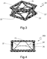
- Figure 3 shows a perspective view of a second embodiment of a tilt module subassembly 20 according to the present invention. Also in this case on elastic cage 21 there are shown only two protrusions 23, 23' of the four protrusions present, and two SMA wires 22, 22' of the four SMA wires present on the tilt module subassembly.
- Figure 4 shows its cross-sectional view with in evidence backbones 26 and 26', whose purpose is to confer structural integrity and at the same time ensure its flexibility once subjected to the forces exerted by one or more SMA wires.
- the second embodiment of figures 3 and 4 uses eight curved backbones such as 26 and 26' connected in pairs, each backbone connecting two adjacent corners of the upper or lower squares of the cage.
- Figure 5a shows a cross-sectional view of a further variant of this embodiment.
- the eight backbones connect the upper and lower squares at the same corner of the tilt module cage, only two of them 36 and 36' being visible in cross-sectional view 30.
- two shape memory alloy wires 32 and 32' connecting corresponding sides of the upper and lower squares of the tilt module cage.
- a return compression spring 37 secured to the upper square, providing further aid for the elastic cage shape recovery after the SMA wire deactivation.
- Figure 5b shows, in a cross-sectional view, the effect of the activation of shape memory alloy wire 32' on the tilt module subassembly.
- tilting is achieved by the cage deformation due to shortening of the shape memory alloy wire 32', while the opposed shape memory alloy wire 32 does not alter its length and is unaffected by operations of the first shape memory alloy wire 32'.
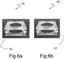
- Figures 6a, 6b show a side by side comparison of two front views of a fourth subassembly tilt module: subassembly 40 represents the case when the shape memory alloy wire 42 is shorter (actuated), whereas subassembly 40' when the shape memory alloy wire 42 is longer (not actuated). Only one wire 42 has been highlighted, but the system uses four wires and their simultaneous control achieves the precise and controlled tilting of the subassembly module. Note that in this case, unlike in the previous embodiments, the activation of the SMA wire(s) 42 moves the upper square away from the lower square by pulling closer and thus extending the backbones with an outwards V-shape that connect the two squares (i.e. the opposite of Figs.5a, 5b ).
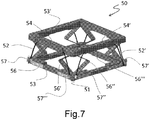
- FIG. 7 shows a perspective view of a fifth embodiment of a tilt module 50 made according to the present invention.
- the elastic cage 51 structure is basically made by two parallel squares 53, 53' connected by eight backbone elements 56, 56', 56", 56''',... (only the most visible four clearly indicated), four shape memory alloy wires, 52, 52',.. (only the most visible two clearly indicated), each having a portion placed within a guide 54, 54' (only the most visible two clearly indicated) where the wire guide is attached to the square 53' that does not have the shape memory alloy wire crimping elements, i.e. the guides have a similar purpose and effect like protrusions 23, 23' of figures 3 and 4 , but with the advantage in this case of providing a more distributed deformation effect onto the cage structure.
- the guide 54' protects and guides a non-activated shape memory alloy wire, such as 52' from being displaced when a shape memory alloy wire is activated on an opposite or perpendicular side of the upper square 53'.
- the complete tilt module is designed to be a single molded part with over-molded metal latches 57, 57', 57", 57''', to crimp the shape memory alloy wires, such as 52', for mechanical and electrical attachment and connection.
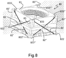
- Figure 8 shows a perspective view of a tilt module subassembly 80 according to a sixth embodiment of the present invention.
- the elastic cage 81 has, on its upper corners, four guides 833, 833', 833", 833'' obtained by having pillars 83, 83', 83", 83''' spaced apart from the elastic cage body.
- Each guide 833, 833', 833", 833''' has the purpose of lodging the central/middle portion of a shape memory alloy wire.
- the tilt module subassembly 80 envisions the use of four shape memory alloy wires, only one of them, element 82, being fully visible in the perspective view of figure 8 , while only half portions 82' and 82" are visible for other two of said shape memory alloy wires.
- four pairs of restraining elements are present on the lower portion of the elastic cage 81, where the extremities of the shape memory alloy wires are firmly held, in the specific case of this embodiment by crimping. Only both restraining elements 822 of the shape memory alloy wire 82 are visible in figure 8 , together with a single element of the pair for restraining elements 822' and 822".
- each shape memory alloy wire 82, 82'... has its extremities anchored to the elastic cage 81 by means of two restraining elements 822, 822'... placed on opposite corners of the elastic cage 81, and its central portion exerts its force on the elastic cage 81 via the guide 833, 833'... formed on the upper corner located between its restraining elements.
- the height difference between the position of the restraining elements 822, 822'... and the position of the shape memory alloy wire guide 833, 833'... allows the shape memory alloy wire to exert its compressive force once activated via heating (current passage).
- a minor variant of the above embodiment envisions the use of four restraining elements, each firmly holding the terminal parts of two adjacent shape memory alloy wires.
- the tilt module subassemblies according to the present invention are not restricted to the use of a specific type of shape memory alloy wires, but any shape memory alloy wires activated by Joule effect may be usefully employed. Having said that, preferred is the use of shape memory alloy wires made with Ni-Ti alloys widely known in the field with the name of Nitinol, with diameters ranging from 10 ⁇ m to 50 ⁇ m and commercially available from a variety of sources, for examples the wires sold under the trade name Smartflex by SAES Getters S.p.A., of particular preference is the use of 25 ⁇ m wires.
- the material or materials for the cage structure of a tilt module subassembly according to the present invention are not restricted or limited to a specific class, they could be metals, plastics, composites, the only requirement being that they have a Young modulus comprised between 13000 and 16000 MPa, preferably between 14000 and 15000 MPa.
- preferred materials for the cage structure are fiber-reinforced liquid crystal polymers.
- the tilt module subassembly according to the present invention may be used in a variety of applications even though among the most interesting there is the use for Optical Image Stabilizers in cell phones camera modules.
- the invention in a second aspect thereof, is inherent to an optical positioning system for consumer electronics or medical devices using micro structures.
- a preferred application is for the Optical Image Stabilizer (OIS) system.
- OIS Optical Image Stabilizer
- the optical positioning system comprises a cage consisting essentially of elastic material and a plurality of shape memory alloy wires, wherein said elastic material has a Young modulus comprised between 13000 and 16000 MPa, preferably between 14000 and 15000 MPa. Additionally, the system applies to any optical positioning of micro mirrors to displace the optical path of light for consumer electronics and medical devices where micro structures need to be used.
- the OIS system comprises also an Auto-Focus (AF) module, and/or a gyroscope.
- AF Auto-Focus
- gyroscope a gyroscope
- the tilt module subassembly of the present invention is easier to make and presents improved performances by exploiting the inventive concept of having the whole (flexible) structure acting in and as counterbalance to the SMA wires, instead of having dedicated components, such as return springs, that provide a localized force whose impact and detrimental effect are lessened, but not eliminated, by the use of additional elements such as sliding spheres. It is important to underline, once again, that such dedicated counterbalance components are absent in a subassembly tilt module according to the present invention, as it is the structure itself providing such function, thanks to the novel and inventive feature (Young modulus in the claimed range) of the used material.
Description
- Actuators based on Shape Memory Alloy (SMA) wires are becoming increasingly adopted due to the intrinsic advantages associated with this technology, in particular their capability to replace micro-motors offers advantages in terms of encumbrance, reliability, power consumption.
- Some of the recent examples of SMA-based actuators are in valves for liquid mixers for vending machines, such as described in the European Patent
EP 2615951 , in anti-glare rear view mirrors, such as described in the international patent applicationWO 2014057423 , and even in sails control systems, such as described in the international patent applicationWO 2014128599 . - The above are just examples of the versatility and possibilities of SMA-based actuators. One particularly interesting application field is tilt modules, for examples to be used in an Optical Image Stabilizer for camera phones, such as described in the international patent application
WO 2013175197 disclosing the use of a plurality of SMA wires working opposite to each other in order to achieve the tilt control. - A solution using a couple of SMA wires is described in
US patent application 2006/0272328 , in this case there is also disclosed the use of an elastic element providing the return force for the SMA wire, such elastic element being an interface between the rigid case and an image pickup unit whose tilt is controlled by two opposed shape memory alloy wires. - Use of SMA wires is also described in European patent application
2813877 , showing a cage made up of a base plate and a driven plate formed of a resin-molding product and held by a support member so as to be in parallel with each other, said support member being made using a suspension wire having a thickness of about 80 µm to about 100 µm so as to be deformed by a driving member made using a linear SMA wire. Such document also teaches the importance of incorporating rigid elements as constitutional features of the structure, more specifically the use of fixing members, made using SUS (stainless) steel or copper-based metal material having a Young modulus of about 50 GPa to 250 GPa, to mechanically fix the SMA wire to the base plate. - The above solutions suffer from a major drawback that resides in the very same SMA property used for actuation, i.e. their capability to contract when heated but their high resistance to be further elongated. This implies that in order to achieve tilt, in normal conditions, the SMA wires shall be partially actuated at a different degree, requiring a higher power consumption and the need of a careful and complicated balance as well as a premature wear of the system.
- Purpose of the present invention is to provide a tilt module capable of overcoming the problems and drawbacks still present in the known art, with particular reference to tilting systems achieving control by means of opposed SMA wires, and in a first aspect thereof consists in a tilt module subassembly comprising a cage consisting essentially of elastic material and a plurality of shape memory alloy wires, wherein said elastic material has a Young modulus comprised between 13000 and 16000 MPa, preferably between 14000 and 15000 MPa.
- The expression "consisting essentially of elastic material" means that the cage may have some appendixes, such as connecting means, that are made with a rigid material, but for the purpose of the present invention at least 90% wt. of the cage material are elastic materials fulfilling the Young modulus requirement above expressed.
- The invention will be further illustrated by means of the following figures where:
-
Figures 1 and 2 are perspective views respectively of a tilt module subassembly and of its cage according to the present invention, -
Figure 3 is a perspective view of a second embodiment of a tilt module subassembly according to the present invention, -
Figure 4 is a cross-sectional view of the tilt module subassembly ofFig.3 , -
Figures 5a and 5b are cross-sectional views of a third embodiment of a tilt module subassembly according to the present invention, -
Figures 6a and 6b are two photos of a tilt module subassembly according to a fourth embodiment of the present invention, -
Figure 7 shows a perspective view of a tilt module subassembly according to a fifth embodiment of the present invention, and -
Figure 8 shows a perspective view of a tilt module subassembly according to a sixth embodiment of the present invention. - In the above figures, dimensions and dimensional ratios may not be correct but in some cases have been altered in order to improve the figure readability; also, elements not essential for the understanding of the invention, such as for example shape memory alloys wires connections and fixings, usually have not been depicted since ancillary and widely known in the technical field.
- For the purpose of the present invention, the term "cage" indicates the skeleton structure of the subassembly without any further element, such as the shape memory alloy wires.
-
Figure 1 shows a perspective view of atilt module 10 according to the present invention, comprising acage 11 made of an elastic material having a Young modulus comprised between 13000 and 16000 MPa. In thisembodiment cage 11 presents four protrusions, only twoprotrusions 13, 13' being visible in the perspective view, the purpose of which is to provide a hook point for each of the four shape memory wires used in the represented embodiment, only twoSMA wires 12, 12' being visible in the perspective view. These hook points represent also the points where the shape memory alloy wires exert their contraction force, upon activation by Joule effect. - The elastic deformation of the
cage structure 11 ensures the tilt of a containedcamera module 14, and at the same time provides the return force for the SMA wire once it is deactivated. - It can be appreciated that the cage deformation provides a decoupling of the opposing and adjacent SMA wires, so that upon activation of one of them, the others are not subjected to a strain, or possibly only to a minimal one, since the strain is to a great extent absorbed by the elastic cage structure itself.
-
Figures 1 and 2 represent a first preferred embodiment for a tilt module subassembly according to the present invention, in which the cage has a structure consisting of twoparallel squares 15, 15', spaced by fourstraight pillars - The main difference between
figures 1 and 2 is the absence of thecamera module 14 and shapememory alloy wires 12, 12' in the latter, that allows for a better appreciation of the cage structure per se. -
Figure 3 shows a perspective view of a second embodiment of atilt module subassembly 20 according to the present invention. Also in this case onelastic cage 21 there are shown only twoprotrusions 23, 23' of the four protrusions present, and twoSMA wires 22, 22' of the four SMA wires present on the tilt module subassembly. -
Figure 4 shows its cross-sectional view with inevidence backbones 26 and 26', whose purpose is to confer structural integrity and at the same time ensure its flexibility once subjected to the forces exerted by one or more SMA wires. - The second embodiment of
figures 3 and 4 uses eight curved backbones such as 26 and 26' connected in pairs, each backbone connecting two adjacent corners of the upper or lower squares of the cage. -
Figure 5a shows a cross-sectional view of a further variant of this embodiment. In this case the eight backbones connect the upper and lower squares at the same corner of the tilt module cage, only two of them 36 and 36' being visible incross-sectional view 30. In the represented third embodiment there are also shown two shapememory alloy wires 32 and 32', connecting corresponding sides of the upper and lower squares of the tilt module cage. Infigure 5a there is also shown areturn compression spring 37, secured to the upper square, providing further aid for the elastic cage shape recovery after the SMA wire deactivation. -
Figure 5b shows, in a cross-sectional view, the effect of the activation of shape memory alloy wire 32' on the tilt module subassembly. As it is possible to observe from this figure, tilting is achieved by the cage deformation due to shortening of the shape memory alloy wire 32', while the opposed shapememory alloy wire 32 does not alter its length and is unaffected by operations of the first shape memory alloy wire 32'. -
Figures 6a, 6b show a side by side comparison of two front views of a fourth subassembly tilt module: subassembly 40 represents the case when the shapememory alloy wire 42 is shorter (actuated), whereas subassembly 40' when the shapememory alloy wire 42 is longer (not actuated). Only onewire 42 has been highlighted, but the system uses four wires and their simultaneous control achieves the precise and controlled tilting of the subassembly module. Note that in this case, unlike in the previous embodiments, the activation of the SMA wire(s) 42 moves the upper square away from the lower square by pulling closer and thus extending the backbones with an outwards V-shape that connect the two squares (i.e. the opposite ofFigs.5a, 5b ). -
Figure 7 shows a perspective view of a fifth embodiment of atilt module 50 made according to the present invention. Theelastic cage 51 structure is basically made by twoparallel squares 53, 53' connected by eightbackbone elements guide 54, 54' (only the most visible two clearly indicated) where the wire guide is attached to the square 53' that does not have the shape memory alloy wire crimping elements, i.e. the guides have a similar purpose and effect likeprotrusions 23, 23' offigures 3 and 4 , but with the advantage in this case of providing a more distributed deformation effect onto the cage structure. - The guide 54' protects and guides a non-activated shape memory alloy wire, such as 52' from being displaced when a shape memory alloy wire is activated on an opposite or perpendicular side of the upper square 53'. The complete tilt module is designed to be a single molded part with over-molded
metal latches -
Figure 8 shows a perspective view of atilt module subassembly 80 according to a sixth embodiment of the present invention. In this case theelastic cage 81 has, on its upper corners, fourguides pillars guide - In particular, the tilt module subassembly 80 envisions the use of four shape memory alloy wires, only one of them,
element 82, being fully visible in the perspective view offigure 8 , while onlyhalf portions 82' and 82" are visible for other two of said shape memory alloy wires. Correspondingly, four pairs of restraining elements are present on the lower portion of theelastic cage 81, where the extremities of the shape memory alloy wires are firmly held, in the specific case of this embodiment by crimping. Only bothrestraining elements 822 of the shapememory alloy wire 82 are visible infigure 8 , together with a single element of the pair forrestraining elements 822' and 822". - So each shape
memory alloy wire 82, 82'... has its extremities anchored to theelastic cage 81 by means of tworestraining elements 822, 822'... placed on opposite corners of theelastic cage 81, and its central portion exerts its force on theelastic cage 81 via theguide 833, 833'... formed on the upper corner located between its restraining elements. The height difference between the position of therestraining elements 822, 822'... and the position of the shape memoryalloy wire guide 833, 833'... allows the shape memory alloy wire to exert its compressive force once activated via heating (current passage). - A minor variant of the above embodiment envisions the use of four restraining elements, each firmly holding the terminal parts of two adjacent shape memory alloy wires.
- Another variant of the above embodiments envisions the use of indentations in the upper surface of the elastic cage to create the guides for the central portions of the shape memory alloy wires.
- The tilt module subassemblies according to the present invention are not restricted to the use of a specific type of shape memory alloy wires, but any shape memory alloy wires activated by Joule effect may be usefully employed. Having said that, preferred is the use of shape memory alloy wires made with Ni-Ti alloys widely known in the field with the name of Nitinol, with diameters ranging from 10 µm to 50 µm and commercially available from a variety of sources, for examples the wires sold under the trade name Smartflex by SAES Getters S.p.A., of particular preference is the use of 25 µm wires.
- The material or materials for the cage structure of a tilt module subassembly according to the present invention are not restricted or limited to a specific class, they could be metals, plastics, composites, the only requirement being that they have a Young modulus comprised between 13000 and 16000 MPa, preferably between 14000 and 15000 MPa.
- Notwithstanding the above, preferred materials for the cage structure are fiber-reinforced liquid crystal polymers.
- The tilt module subassembly according to the present invention may be used in a variety of applications even though among the most interesting there is the use for Optical Image Stabilizers in cell phones camera modules. In view of this, in a second aspect thereof, the invention is inherent to an optical positioning system for consumer electronics or medical devices using micro structures. A preferred application is for the Optical Image Stabilizer (OIS) system.
- The optical positioning system according to the present invention comprises a cage consisting essentially of elastic material and a plurality of shape memory alloy wires, wherein said elastic material has a Young modulus comprised between 13000 and 16000 MPa, preferably between 14000 and 15000 MPa. Additionally, the system applies to any optical positioning of micro mirrors to displace the optical path of light for consumer electronics and medical devices where micro structures need to be used.
- Preferably the OIS system comprises also an Auto-Focus (AF) module, and/or a gyroscope.
- The tilt module subassembly of the present invention is easier to make and presents improved performances by exploiting the inventive concept of having the whole (flexible) structure acting in and as counterbalance to the SMA wires, instead of having dedicated components, such as return springs, that provide a localized force whose impact and detrimental effect are lessened, but not eliminated, by the use of additional elements such as sliding spheres. It is important to underline, once again, that such dedicated counterbalance components are absent in a subassembly tilt module according to the present invention, as it is the structure itself providing such function, thanks to the novel and inventive feature (Young modulus in the claimed range) of the used material.
Claims (21)
- A tilt module subassembly (10; 20; 200; 30; 30'; 40; 40'; 50; 80) for a camera module (14), comprising a cage (11; 21; 51; 81) consisting essentially of elastic material, said cage (11; 21; 51; 81) having a structure formed by two parallel squares (15, 15'; 53, 53') spaced by at least four spacing elements, and a plurality of shape memory alloy wires (12, 12'; 22, 22'; 32, 32'; 42; 52, 52'; 82, 82', 82") as actuating members acting on said structure of said cage (11; 21; 51; 81), wherein said elastic material has a Young modulus comprised between 13000 and 16000 MPa.
- A tilt module subassembly (10; 20; 200; 30; 30'; 40; 40'; 50; 80) according to claim 1, wherein said shape memory alloy wires (12, 12'; 22, 22'; 32, 32'; 42; 52, 52'; 82, 82', 82") are disposed symmetrically with respect to a cage symmetry axis.
- A tilt module subassembly (10; 20; 200; 30; 30'; 40; 40'; 50; 80) according to claims 1 or 2, wherein the number of shape memory wires (12, 12'; 22, 22'; 32, 32'; 42; 52, 52'; 82, 82', 82") is four.
- A tilt module subassembly (10) according to any of the previous claims, wherein said cage (11) has a structure consisting of two parallel squares (15, 15') spaced by four pillars (16, 16', 16", 16''') connecting the corresponding corners of said two parallel squares (15, 15').
- A tilt module subassembly (10) according to claim 4, wherein on at least one side of a square (15') there is a protrusion (13, 13') in the central portion of the square side for hooking and restraining a shape memory alloy wire (12, 12').
- A tilt module subassembly (20; 200; 30; 30'; 40; 40';50) according to any of claims 1 to 3, wherein said cage (21; 51) has a structure given by two parallel squares (53, 53') spaced by eight angled backbones (26, 26'; 36, 36'; 56, 56', 56", 56''').
- A tilt module subassembly (20; 200; 30; 30') according to claim 6, wherein each backbone (26, 26') connects two adjacent corners of a same square.
- A tilt module subassembly (20; 200) according to claim 7, wherein on at least one side of a square there is a protrusion (23, 23') in the central portion of the square side for hooking and restraining a shape memory alloy wire (22, 22').
- A tilt module subassembly (40; 40';50) according to claim 6, wherein each backbone (36, 36'; 56, 56', 56", 56''') connects corresponding corners of the two squares (53, 53').
- A tilt module subassembly (50) according to claim 9, wherein on at least one side of a square (53') there is a linear guide (54, 54') for the shape memory alloy wire (52, 52').
- A tilt module subassembly (40) according to claim 9, wherein each of the shape memory alloy wires (42) connects adjacent backbones.
- A tilt module subassembly (80) according to claim 3, wherein the cage (81) has a square shape and on each of the four corners of the cage there is a guide (833, 833', 833", 833''') for respectively lodging the central portion of each one of the four shape memory wires (82, 82', 82").
- A tilt module subassembly (80) according to claim 12, wherein said guides (833, 833', 833", 833''') are formed by a spacing between the cage (81) and four pillars (83, 83', 83", 83'''), each of said pillars (83, 83', 83", 83''') being placed on one of the four corners of the elastic cage (81).
- A tilt module subassembly (80) according to claim 12, wherein said guides (833, 833', 833", 833''') are formed by indentations in the four corners of the cage (81).
- A tilt module subassembly (80) according to any of claims 12 to 14, wherein each shape memory alloy wire (82, 82', 82") is anchored to the cage structure by means of restraining elements (822, 822', 822") placed on opposing corners, where such restraining elements (822, 822', 822") are at the same height.
- A ilt module subassembly (80) according to claim 15, wherein the number of said restraining elements (822, 822', 822") is four or eight.
- A tilt module subassembly (10; 20; 200; 30; 30'; 40; 40'; 50; 80) according to any of the preceding claims, wherein the elastic material of the cage (11; 21; 51; 81) has a Young modulus comprised between 14000 and 15000 MPa.
- An optical image positioning system for microstructures characterized by comprising a tilt module subassembly (10; 20; 200; 30; 30'; 40; 40'; 50; 80) according to any of the previous claims.
- An optical image positioning system for microstructures according to the preceding claim 18, wherein said optical image positioning system is an Optical Image Stabilizer (OIS).
- An Optical Image Stabilizer (OIS) system according to the preceding claim 19, further comprising an Auto-Focus (AF) module.
- An Optical Image Stabilizer (OIS) system according to claim 19 or 20, further comprising a gyroscope.
Applications Claiming Priority (2)
| Application Number | Priority Date | Filing Date | Title |
|---|---|---|---|
| ITMI20150635 | 2015-05-05 | ||
| PCT/IB2016/052535 WO2016178152A1 (en) | 2015-05-05 | 2016-05-04 | Tilt module subassembly and optical image stabilizer comprising it |
Publications (2)
| Publication Number | Publication Date |
|---|---|
| EP3268807A1 EP3268807A1 (en) | 2018-01-17 |
| EP3268807B1 true EP3268807B1 (en) | 2018-08-22 |
Family
ID=53539795
Family Applications (1)
| Application Number | Title | Priority Date | Filing Date |
|---|---|---|---|
| EP16722382.5A Active EP3268807B1 (en) | 2015-05-05 | 2016-05-04 | Tilt module subassembly and optical image stabilizer comprising it |
Country Status (7)
| Country | Link |
|---|---|
| US (1) | US9933689B2 (en) |
| EP (1) | EP3268807B1 (en) |
| JP (1) | JP6619444B2 (en) |
| KR (1) | KR102272706B1 (en) |
| CN (1) | CN107407851B (en) |
| TW (1) | TWI677744B (en) |
| WO (1) | WO2016178152A1 (en) |
Families Citing this family (27)
| Publication number | Priority date | Publication date | Assignee | Title |
|---|---|---|---|---|
| IT201600125596A1 (en) | 2016-12-13 | 2018-06-13 | Actuator Solutions GmbH | Optical image stabilizer |
| GB201703356D0 (en) * | 2017-03-02 | 2017-04-19 | Cambridge Mechatronics Ltd | SMA actuator for zoom camera OIS |
| IT201700048138A1 (en) * | 2017-05-04 | 2018-11-04 | Actuator Solutions GmbH | Camera module auto-focus actuator |
| US11815794B2 (en) | 2017-05-05 | 2023-11-14 | Hutchinson Technology Incorporated | Shape memory alloy actuators and methods thereof |
| KR102565644B1 (en) | 2017-05-05 | 2023-08-10 | 허친슨 테크놀로지 인코포레이티드 | Shape memory alloy actuator and method |
| US11306706B2 (en) * | 2017-05-05 | 2022-04-19 | Hutchinson Technology Incorporated | Shape memory alloy actuators and methods thereof |
| US11448853B2 (en) | 2017-05-05 | 2022-09-20 | Hutchinson Technology Incorporated | Shape memory alloy actuators and methods thereof |
| US11333134B2 (en) * | 2017-05-05 | 2022-05-17 | Hutchinson Technology Incorporated | Shape memory alloy actuators and methods thereof |
| CN109725473B (en) * | 2017-10-30 | 2021-09-28 | 台湾东电化股份有限公司 | Optical drive mechanism |
| US11226469B2 (en) | 2017-10-30 | 2022-01-18 | Tdk Taiwan Corp. | Optical driving mechanism |
| GB2572422B (en) * | 2018-03-29 | 2020-06-10 | Cambridge Mechatronics Ltd | Apparatus and methods for assembling an actuating module |
| KR102584971B1 (en) * | 2018-07-06 | 2023-10-05 | 삼성전기주식회사 | Camera module |
| KR102584983B1 (en) * | 2018-07-09 | 2023-10-05 | 삼성전기주식회사 | Camera module |
| KR102125086B1 (en) * | 2018-08-28 | 2020-06-19 | 삼성전기주식회사 | Camera module |
| WO2020243864A1 (en) * | 2019-06-01 | 2020-12-10 | 瑞声光学解决方案私人有限公司 | Prism apparatus applied to periscopic lens module, and periscopic lens module |
| JP6995212B2 (en) * | 2019-06-01 | 2022-01-14 | エーエーシー オプティックス ソリューションズ ピーティーイー リミテッド | Prism device and periscope lens module applied to periscope lens module |
| WO2020243860A1 (en) * | 2019-06-01 | 2020-12-10 | 瑞声光学解决方案私人有限公司 | Optical anti-vibration lens assembly and optical anti-vibration method therefor |
| WO2020243863A1 (en) * | 2019-06-01 | 2020-12-10 | 瑞声光学解决方案私人有限公司 | Prism device applied to periscopic lens module and periscopic lens module |
| JP7060698B2 (en) * | 2019-06-01 | 2022-04-26 | エーエーシー オプティックス ソリューションズ ピーティーイー リミテッド | Lens prism module |
| WO2020243870A1 (en) * | 2019-06-01 | 2020-12-10 | 瑞声光学解决方案私人有限公司 | Prism device applied to periscope-type lens module, and periscope-type lens module |
| US11513310B2 (en) * | 2019-10-03 | 2022-11-29 | Actuator Solutions GmbH | Cylindrical actuator subassembly with flexure-based linear guidance mechanism |
| GB2588965B (en) * | 2019-11-16 | 2022-11-30 | Cambridge Mechatronics Ltd | An actuator and a method of controlling thereof |
| CN113464777A (en) * | 2020-03-31 | 2021-10-01 | 斯玛特技研有限公司 | Camera module side-tipping anti-shake mechanism using SMA wire |
| CN111561635B (en) * | 2020-04-18 | 2021-07-06 | 睿恩光电有限责任公司 | Tiltable imaging system and electronic equipment |
| KR20230021138A (en) * | 2020-06-09 | 2023-02-13 | 허친슨 테크놀로지 인코포레이티드 | Shape memory alloy actuator and method |
| US11859598B2 (en) | 2021-06-10 | 2024-01-02 | Hutchinson Technology Incorporated | Shape memory alloy actuators and methods thereof |
| CN114114786A (en) | 2021-12-01 | 2022-03-01 | 常州市瑞泰光电有限公司 | Lens driving device |
Family Cites Families (28)
| Publication number | Priority date | Publication date | Assignee | Title |
|---|---|---|---|---|
| US6622558B2 (en) * | 2000-11-30 | 2003-09-23 | Orbital Research Inc. | Method and sensor for detecting strain using shape memory alloys |
| JP4735060B2 (en) | 2005-06-06 | 2011-07-27 | コニカミノルタオプト株式会社 | Drive device and image stabilization system |
| KR100748243B1 (en) * | 2005-11-17 | 2007-08-09 | 삼성전기주식회사 | Lens driving device and camera module |
| GB0606425D0 (en) * | 2006-03-30 | 2006-05-10 | 1 Ltd | Camera lens actuation apparatus |
| WO2007113478A1 (en) | 2006-03-30 | 2007-10-11 | 1...Limited | Camera lens actuation apparatus |
| JP2008020813A (en) * | 2006-07-14 | 2008-01-31 | Konica Minolta Opto Inc | Lens driving mechanism and imaging apparatus using same |
| EP2223169A4 (en) * | 2007-12-10 | 2011-05-25 | Artificial Muscle Inc | Optical lens image stabilization systems |
| KR20090081855A (en) * | 2008-01-25 | 2009-07-29 | 이-핀 옵티칼 인더스트리 컴퍼니 리미티드 | Lens displacement mechanism using shaped memory alloy |
| JP5702735B2 (en) * | 2009-02-09 | 2015-04-15 | ケンブリッジ メカトロニクス リミテッド | Optical image stabilization |
| KR101044219B1 (en) * | 2009-10-19 | 2011-06-29 | 삼성전기주식회사 | Lens actuating module |
| US20110217031A1 (en) * | 2010-03-03 | 2011-09-08 | Nokia Corporation | Method And Apparatus For Shape Memory Alloy Bender Actuator |
| JP2011209467A (en) * | 2010-03-29 | 2011-10-20 | Seiko Instruments Inc | Drive module and electronic device |
| KR101912093B1 (en) * | 2010-10-29 | 2018-10-26 | 삼성전자 주식회사 | Optical apparatus |
| JP2012237855A (en) * | 2011-05-11 | 2012-12-06 | Sony Corp | Lens module, imaging apparatus, electronic apparatus and drive method of lens module |
| JP5329629B2 (en) * | 2011-09-26 | 2013-10-30 | シャープ株式会社 | The camera module |
| ITMI20112121A1 (en) | 2011-11-22 | 2013-05-23 | Getters Spa | SYSTEM FOR THE PRODUCTION OF HOT WATER AND AUTOMATIC DRINK OF DRINKS THAT USES IT |
| US8731390B2 (en) * | 2012-01-12 | 2014-05-20 | Corephotonics Ltd. | Electromagnetic actuators for digital cameras |
| WO2013118601A1 (en) * | 2012-02-07 | 2013-08-15 | コニカミノルタホールディングス株式会社 | Drive device and lens unit |
| CN104204935B (en) * | 2012-02-16 | 2017-05-10 | 剑桥机电有限公司 | shape memory alloy actuation apparatus |
| JP2013195512A (en) * | 2012-03-16 | 2013-09-30 | Konica Minolta Inc | Driving mechanism and lens driving mechanism |
| JP2013242426A (en) * | 2012-05-21 | 2013-12-05 | Konica Minolta Inc | Drive mechanism and lens moving mechanism |
| US9518566B2 (en) | 2012-05-25 | 2016-12-13 | Cambridge Mechatronics Limited | Shape memory alloy actuation apparatus |
| TWI548929B (en) | 2012-07-30 | 2016-09-11 | 鴻海精密工業股份有限公司 | Image stabilizer and image capturing device |
| CN103576414B (en) * | 2012-07-31 | 2018-04-20 | 深圳众赢时代科技有限公司 | Image stabilizer and image-taking device |
| ITMI20121705A1 (en) | 2012-10-10 | 2014-04-11 | Getters Spa | BISTABLE ELECTRIC SWITCH WITH SHAPE MEMORY ACTUATOR |
| ITMI20122099A1 (en) * | 2012-12-10 | 2014-06-11 | Getters Spa | AUTO-FOCUS DEVICE WITH SHAPE MEMORY ACTUATOR |
| ITGE20130021A1 (en) | 2013-02-19 | 2014-08-20 | Ing Andrea Dogliotti | APPARATUS FOR THE QUICK AND PRECISION ADJUSTMENT OF THE SAILINGS OF THE BOATS |
| US9793829B2 (en) * | 2013-09-25 | 2017-10-17 | Prime Photonics, Lc | Magneto-thermoelectric generator for energy harvesting |
-
2016
- 2016-05-04 US US15/558,481 patent/US9933689B2/en active Active
- 2016-05-04 EP EP16722382.5A patent/EP3268807B1/en active Active
- 2016-05-04 TW TW105113834A patent/TWI677744B/en active
- 2016-05-04 JP JP2017549464A patent/JP6619444B2/en active Active
- 2016-05-04 CN CN201680017437.3A patent/CN107407851B/en active Active
- 2016-05-04 WO PCT/IB2016/052535 patent/WO2016178152A1/en active Application Filing
- 2016-05-04 KR KR1020177026575A patent/KR102272706B1/en active IP Right Grant
Non-Patent Citations (1)
| Title |
|---|
| None * |
Also Published As
| Publication number | Publication date |
|---|---|
| KR20180003532A (en) | 2018-01-09 |
| WO2016178152A1 (en) | 2016-11-10 |
| JP2018522256A (en) | 2018-08-09 |
| US9933689B2 (en) | 2018-04-03 |
| TW201710773A (en) | 2017-03-16 |
| CN107407851B (en) | 2020-05-19 |
| JP6619444B2 (en) | 2019-12-11 |
| US20180052381A1 (en) | 2018-02-22 |
| TWI677744B (en) | 2019-11-21 |
| CN107407851A (en) | 2017-11-28 |
| EP3268807A1 (en) | 2018-01-17 |
| KR102272706B1 (en) | 2021-07-05 |
Similar Documents
| Publication | Publication Date | Title |
|---|---|---|
| EP3268807B1 (en) | Tilt module subassembly and optical image stabilizer comprising it | |
| EP3619576B1 (en) | Camera module autofocus actuator | |
| US8073320B2 (en) | Shape memory alloy actuation apparatus | |
| EP3210078B1 (en) | Camera module autofocus actuator and control method thereof | |
| EP3497517B1 (en) | Optical image stabilizer | |
| US8588598B2 (en) | Shape memory alloy actuation apparatus | |
| US20150322929A1 (en) | Drive device and lens unit | |
| CN110709757A (en) | Shape memory alloy actuator and method thereof | |
| EP4136491A1 (en) | Actuator assembly | |
| WO2023002188A1 (en) | Sma actuator assembly |
Legal Events
| Date | Code | Title | Description |
|---|---|---|---|
| STAA | Information on the status of an ep patent application or granted ep patent |
Free format text: STATUS: THE INTERNATIONAL PUBLICATION HAS BEEN MADE |
|
| PUAI | Public reference made under article 153(3) epc to a published international application that has entered the european phase |
Free format text: ORIGINAL CODE: 0009012 |
|
| STAA | Information on the status of an ep patent application or granted ep patent |
Free format text: STATUS: REQUEST FOR EXAMINATION WAS MADE |
|
| 17P | Request for examination filed |
Effective date: 20170911 |
|
| AK | Designated contracting states |
Kind code of ref document: A1 Designated state(s): AL AT BE BG CH CY CZ DE DK EE ES FI FR GB GR HR HU IE IS IT LI LT LU LV MC MK MT NL NO PL PT RO RS SE SI SK SM TR |
|
| AX | Request for extension of the european patent |
Extension state: BA ME |
|
| REG | Reference to a national code |
Ref country code: DE Ref legal event code: R079 Ref document number: 602016005026 Country of ref document: DE Free format text: PREVIOUS MAIN CLASS: G03B0017020000 Ipc: G03B0005000000 |
|
| RIC1 | Information provided on ipc code assigned before grant |
Ipc: G03B 5/00 20060101AFI20180213BHEP |
|
| GRAP | Despatch of communication of intention to grant a patent |
Free format text: ORIGINAL CODE: EPIDOSNIGR1 |
|
| STAA | Information on the status of an ep patent application or granted ep patent |
Free format text: STATUS: GRANT OF PATENT IS INTENDED |
|
| INTG | Intention to grant announced |
Effective date: 20180327 |
|
| GRAS | Grant fee paid |
Free format text: ORIGINAL CODE: EPIDOSNIGR3 |
|
| GRAA | (expected) grant |
Free format text: ORIGINAL CODE: 0009210 |
|
| STAA | Information on the status of an ep patent application or granted ep patent |
Free format text: STATUS: THE PATENT HAS BEEN GRANTED |
|
| DAV | Request for validation of the european patent (deleted) | ||
| DAX | Request for extension of the european patent (deleted) | ||
| AK | Designated contracting states |
Kind code of ref document: B1 Designated state(s): AL AT BE BG CH CY CZ DE DK EE ES FI FR GB GR HR HU IE IS IT LI LT LU LV MC MK MT NL NO PL PT RO RS SE SI SK SM TR |
|
| REG | Reference to a national code |
Ref country code: GB Ref legal event code: FG4D |
|
| REG | Reference to a national code |
Ref country code: CH Ref legal event code: EP |
|
| REG | Reference to a national code |
Ref country code: AT Ref legal event code: REF Ref document number: 1033168 Country of ref document: AT Kind code of ref document: T Effective date: 20180915 |
|
| REG | Reference to a national code |
Ref country code: IE Ref legal event code: FG4D |
|
| REG | Reference to a national code |
Ref country code: DE Ref legal event code: R096 Ref document number: 602016005026 Country of ref document: DE |
|
| REG | Reference to a national code |
Ref country code: NL Ref legal event code: MP Effective date: 20180822 |
|
| REG | Reference to a national code |
Ref country code: LT Ref legal event code: MG4D |
|
| PG25 | Lapsed in a contracting state [announced via postgrant information from national office to epo] |
Ref country code: NO Free format text: LAPSE BECAUSE OF FAILURE TO SUBMIT A TRANSLATION OF THE DESCRIPTION OR TO PAY THE FEE WITHIN THE PRESCRIBED TIME-LIMIT Effective date: 20181122 Ref country code: RS Free format text: LAPSE BECAUSE OF FAILURE TO SUBMIT A TRANSLATION OF THE DESCRIPTION OR TO PAY THE FEE WITHIN THE PRESCRIBED TIME-LIMIT Effective date: 20180822 Ref country code: SE Free format text: LAPSE BECAUSE OF FAILURE TO SUBMIT A TRANSLATION OF THE DESCRIPTION OR TO PAY THE FEE WITHIN THE PRESCRIBED TIME-LIMIT Effective date: 20180822 Ref country code: GR Free format text: LAPSE BECAUSE OF FAILURE TO SUBMIT A TRANSLATION OF THE DESCRIPTION OR TO PAY THE FEE WITHIN THE PRESCRIBED TIME-LIMIT Effective date: 20181123 Ref country code: FI Free format text: LAPSE BECAUSE OF FAILURE TO SUBMIT A TRANSLATION OF THE DESCRIPTION OR TO PAY THE FEE WITHIN THE PRESCRIBED TIME-LIMIT Effective date: 20180822 Ref country code: IS Free format text: LAPSE BECAUSE OF FAILURE TO SUBMIT A TRANSLATION OF THE DESCRIPTION OR TO PAY THE FEE WITHIN THE PRESCRIBED TIME-LIMIT Effective date: 20181222 Ref country code: NL Free format text: LAPSE BECAUSE OF FAILURE TO SUBMIT A TRANSLATION OF THE DESCRIPTION OR TO PAY THE FEE WITHIN THE PRESCRIBED TIME-LIMIT Effective date: 20180822 Ref country code: LT Free format text: LAPSE BECAUSE OF FAILURE TO SUBMIT A TRANSLATION OF THE DESCRIPTION OR TO PAY THE FEE WITHIN THE PRESCRIBED TIME-LIMIT Effective date: 20180822 Ref country code: BG Free format text: LAPSE BECAUSE OF FAILURE TO SUBMIT A TRANSLATION OF THE DESCRIPTION OR TO PAY THE FEE WITHIN THE PRESCRIBED TIME-LIMIT Effective date: 20181122 |
|
| REG | Reference to a national code |
Ref country code: AT Ref legal event code: MK05 Ref document number: 1033168 Country of ref document: AT Kind code of ref document: T Effective date: 20180822 |
|
| PG25 | Lapsed in a contracting state [announced via postgrant information from national office to epo] |
Ref country code: AL Free format text: LAPSE BECAUSE OF FAILURE TO SUBMIT A TRANSLATION OF THE DESCRIPTION OR TO PAY THE FEE WITHIN THE PRESCRIBED TIME-LIMIT Effective date: 20180822 Ref country code: LV Free format text: LAPSE BECAUSE OF FAILURE TO SUBMIT A TRANSLATION OF THE DESCRIPTION OR TO PAY THE FEE WITHIN THE PRESCRIBED TIME-LIMIT Effective date: 20180822 Ref country code: HR Free format text: LAPSE BECAUSE OF FAILURE TO SUBMIT A TRANSLATION OF THE DESCRIPTION OR TO PAY THE FEE WITHIN THE PRESCRIBED TIME-LIMIT Effective date: 20180822 |
|
| PG25 | Lapsed in a contracting state [announced via postgrant information from national office to epo] |
Ref country code: PL Free format text: LAPSE BECAUSE OF FAILURE TO SUBMIT A TRANSLATION OF THE DESCRIPTION OR TO PAY THE FEE WITHIN THE PRESCRIBED TIME-LIMIT Effective date: 20180822 Ref country code: EE Free format text: LAPSE BECAUSE OF FAILURE TO SUBMIT A TRANSLATION OF THE DESCRIPTION OR TO PAY THE FEE WITHIN THE PRESCRIBED TIME-LIMIT Effective date: 20180822 Ref country code: AT Free format text: LAPSE BECAUSE OF FAILURE TO SUBMIT A TRANSLATION OF THE DESCRIPTION OR TO PAY THE FEE WITHIN THE PRESCRIBED TIME-LIMIT Effective date: 20180822 Ref country code: RO Free format text: LAPSE BECAUSE OF FAILURE TO SUBMIT A TRANSLATION OF THE DESCRIPTION OR TO PAY THE FEE WITHIN THE PRESCRIBED TIME-LIMIT Effective date: 20180822 Ref country code: CZ Free format text: LAPSE BECAUSE OF FAILURE TO SUBMIT A TRANSLATION OF THE DESCRIPTION OR TO PAY THE FEE WITHIN THE PRESCRIBED TIME-LIMIT Effective date: 20180822 Ref country code: ES Free format text: LAPSE BECAUSE OF FAILURE TO SUBMIT A TRANSLATION OF THE DESCRIPTION OR TO PAY THE FEE WITHIN THE PRESCRIBED TIME-LIMIT Effective date: 20180822 |
|
| REG | Reference to a national code |
Ref country code: DE Ref legal event code: R097 Ref document number: 602016005026 Country of ref document: DE |
|
| PG25 | Lapsed in a contracting state [announced via postgrant information from national office to epo] |
Ref country code: SK Free format text: LAPSE BECAUSE OF FAILURE TO SUBMIT A TRANSLATION OF THE DESCRIPTION OR TO PAY THE FEE WITHIN THE PRESCRIBED TIME-LIMIT Effective date: 20180822 Ref country code: SM Free format text: LAPSE BECAUSE OF FAILURE TO SUBMIT A TRANSLATION OF THE DESCRIPTION OR TO PAY THE FEE WITHIN THE PRESCRIBED TIME-LIMIT Effective date: 20180822 Ref country code: DK Free format text: LAPSE BECAUSE OF FAILURE TO SUBMIT A TRANSLATION OF THE DESCRIPTION OR TO PAY THE FEE WITHIN THE PRESCRIBED TIME-LIMIT Effective date: 20180822 |
|
| PLBE | No opposition filed within time limit |
Free format text: ORIGINAL CODE: 0009261 |
|
| STAA | Information on the status of an ep patent application or granted ep patent |
Free format text: STATUS: NO OPPOSITION FILED WITHIN TIME LIMIT |
|
| 26N | No opposition filed |
Effective date: 20190523 |
|
| PG25 | Lapsed in a contracting state [announced via postgrant information from national office to epo] |
Ref country code: SI Free format text: LAPSE BECAUSE OF FAILURE TO SUBMIT A TRANSLATION OF THE DESCRIPTION OR TO PAY THE FEE WITHIN THE PRESCRIBED TIME-LIMIT Effective date: 20180822 |
|
| REG | Reference to a national code |
Ref country code: CH Ref legal event code: PL |
|
| PG25 | Lapsed in a contracting state [announced via postgrant information from national office to epo] |
Ref country code: MC Free format text: LAPSE BECAUSE OF FAILURE TO SUBMIT A TRANSLATION OF THE DESCRIPTION OR TO PAY THE FEE WITHIN THE PRESCRIBED TIME-LIMIT Effective date: 20180822 Ref country code: LI Free format text: LAPSE BECAUSE OF NON-PAYMENT OF DUE FEES Effective date: 20190531 Ref country code: CH Free format text: LAPSE BECAUSE OF NON-PAYMENT OF DUE FEES Effective date: 20190531 |
|
| REG | Reference to a national code |
Ref country code: BE Ref legal event code: MM Effective date: 20190531 |
|
| PG25 | Lapsed in a contracting state [announced via postgrant information from national office to epo] |
Ref country code: LU Free format text: LAPSE BECAUSE OF NON-PAYMENT OF DUE FEES Effective date: 20190504 |
|
| PG25 | Lapsed in a contracting state [announced via postgrant information from national office to epo] |
Ref country code: TR Free format text: LAPSE BECAUSE OF FAILURE TO SUBMIT A TRANSLATION OF THE DESCRIPTION OR TO PAY THE FEE WITHIN THE PRESCRIBED TIME-LIMIT Effective date: 20180822 |
|
| PG25 | Lapsed in a contracting state [announced via postgrant information from national office to epo] |
Ref country code: IE Free format text: LAPSE BECAUSE OF NON-PAYMENT OF DUE FEES Effective date: 20190504 |
|
| PG25 | Lapsed in a contracting state [announced via postgrant information from national office to epo] |
Ref country code: BE Free format text: LAPSE BECAUSE OF NON-PAYMENT OF DUE FEES Effective date: 20190531 |
|
| PG25 | Lapsed in a contracting state [announced via postgrant information from national office to epo] |
Ref country code: PT Free format text: LAPSE BECAUSE OF FAILURE TO SUBMIT A TRANSLATION OF THE DESCRIPTION OR TO PAY THE FEE WITHIN THE PRESCRIBED TIME-LIMIT Effective date: 20181222 |
|
| PG25 | Lapsed in a contracting state [announced via postgrant information from national office to epo] |
Ref country code: CY Free format text: LAPSE BECAUSE OF FAILURE TO SUBMIT A TRANSLATION OF THE DESCRIPTION OR TO PAY THE FEE WITHIN THE PRESCRIBED TIME-LIMIT Effective date: 20180822 |
|
| PG25 | Lapsed in a contracting state [announced via postgrant information from national office to epo] |
Ref country code: MT Free format text: LAPSE BECAUSE OF FAILURE TO SUBMIT A TRANSLATION OF THE DESCRIPTION OR TO PAY THE FEE WITHIN THE PRESCRIBED TIME-LIMIT Effective date: 20180822 Ref country code: HU Free format text: LAPSE BECAUSE OF FAILURE TO SUBMIT A TRANSLATION OF THE DESCRIPTION OR TO PAY THE FEE WITHIN THE PRESCRIBED TIME-LIMIT; INVALID AB INITIO Effective date: 20160504 |
|
| PG25 | Lapsed in a contracting state [announced via postgrant information from national office to epo] |
Ref country code: MK Free format text: LAPSE BECAUSE OF FAILURE TO SUBMIT A TRANSLATION OF THE DESCRIPTION OR TO PAY THE FEE WITHIN THE PRESCRIBED TIME-LIMIT Effective date: 20180822 |
|
| P01 | Opt-out of the competence of the unified patent court (upc) registered |
Effective date: 20230521 |
|
| PGFP | Annual fee paid to national office [announced via postgrant information from national office to epo] |
Ref country code: IT Payment date: 20230519 Year of fee payment: 8 Ref country code: FR Payment date: 20230526 Year of fee payment: 8 Ref country code: DE Payment date: 20230530 Year of fee payment: 8 |
|
| PGFP | Annual fee paid to national office [announced via postgrant information from national office to epo] |
Ref country code: GB Payment date: 20230529 Year of fee payment: 8 |