EP3268738B1 - Wrist worn mobile alcohol and offender monitoring system - Google Patents
Wrist worn mobile alcohol and offender monitoring system Download PDFInfo
- Publication number
- EP3268738B1 EP3268738B1 EP16710586.5A EP16710586A EP3268738B1 EP 3268738 B1 EP3268738 B1 EP 3268738B1 EP 16710586 A EP16710586 A EP 16710586A EP 3268738 B1 EP3268738 B1 EP 3268738B1
- Authority
- EP
- European Patent Office
- Prior art keywords
- user
- module
- alcohol detection
- alcohol
- image
- Prior art date
- Legal status (The legal status is an assumption and is not a legal conclusion. Google has not performed a legal analysis and makes no representation as to the accuracy of the status listed.)
- Active
Links
Images



Classifications
-
- A—HUMAN NECESSITIES
- A61—MEDICAL OR VETERINARY SCIENCE; HYGIENE
- A61B—DIAGNOSIS; SURGERY; IDENTIFICATION
- A61B5/00—Measuring for diagnostic purposes; Identification of persons
- A61B5/08—Measuring devices for evaluating the respiratory organs
- A61B5/082—Evaluation by breath analysis, e.g. determination of the chemical composition of exhaled breath
-
- A—HUMAN NECESSITIES
- A61—MEDICAL OR VETERINARY SCIENCE; HYGIENE
- A61B—DIAGNOSIS; SURGERY; IDENTIFICATION
- A61B5/00—Measuring for diagnostic purposes; Identification of persons
- A61B5/08—Measuring devices for evaluating the respiratory organs
- A61B5/097—Devices for facilitating collection of breath or for directing breath into or through measuring devices
-
- A—HUMAN NECESSITIES
- A61—MEDICAL OR VETERINARY SCIENCE; HYGIENE
- A61B—DIAGNOSIS; SURGERY; IDENTIFICATION
- A61B5/00—Measuring for diagnostic purposes; Identification of persons
- A61B5/103—Measuring devices for testing the shape, pattern, colour, size or movement of the body or parts thereof, for diagnostic purposes
- A61B5/11—Measuring movement of the entire body or parts thereof, e.g. head or hand tremor or mobility of a limb
- A61B5/1112—Global tracking of patients, e.g. by using GPS
-
- A—HUMAN NECESSITIES
- A61—MEDICAL OR VETERINARY SCIENCE; HYGIENE
- A61B—DIAGNOSIS; SURGERY; IDENTIFICATION
- A61B5/00—Measuring for diagnostic purposes; Identification of persons
- A61B5/117—Identification of persons
- A61B5/1171—Identification of persons based on the shapes or appearances of their bodies or parts thereof
-
- A—HUMAN NECESSITIES
- A61—MEDICAL OR VETERINARY SCIENCE; HYGIENE
- A61B—DIAGNOSIS; SURGERY; IDENTIFICATION
- A61B5/00—Measuring for diagnostic purposes; Identification of persons
- A61B5/48—Other medical applications
- A61B5/4845—Toxicology, e.g. by detection of alcohol, drug or toxic products
-
- A—HUMAN NECESSITIES
- A61—MEDICAL OR VETERINARY SCIENCE; HYGIENE
- A61B—DIAGNOSIS; SURGERY; IDENTIFICATION
- A61B5/00—Measuring for diagnostic purposes; Identification of persons
- A61B5/68—Arrangements of detecting, measuring or recording means, e.g. sensors, in relation to patient
- A61B5/6801—Arrangements of detecting, measuring or recording means, e.g. sensors, in relation to patient specially adapted to be attached to or worn on the body surface
- A61B5/6802—Sensor mounted on worn items
- A61B5/681—Wristwatch-type devices
-
- A—HUMAN NECESSITIES
- A61—MEDICAL OR VETERINARY SCIENCE; HYGIENE
- A61B—DIAGNOSIS; SURGERY; IDENTIFICATION
- A61B5/00—Measuring for diagnostic purposes; Identification of persons
- A61B5/68—Arrangements of detecting, measuring or recording means, e.g. sensors, in relation to patient
- A61B5/6801—Arrangements of detecting, measuring or recording means, e.g. sensors, in relation to patient specially adapted to be attached to or worn on the body surface
- A61B5/683—Means for maintaining contact with the body
- A61B5/6831—Straps, bands or harnesses
-
- G—PHYSICS
- G01—MEASURING; TESTING
- G01N—INVESTIGATING OR ANALYSING MATERIALS BY DETERMINING THEIR CHEMICAL OR PHYSICAL PROPERTIES
- G01N33/00—Investigating or analysing materials by specific methods not covered by groups G01N1/00 - G01N31/00
- G01N33/48—Biological material, e.g. blood, urine; Haemocytometers
- G01N33/483—Physical analysis of biological material
- G01N33/497—Physical analysis of biological material of gaseous biological material, e.g. breath
- G01N33/4972—Determining alcohol content
-
- A—HUMAN NECESSITIES
- A61—MEDICAL OR VETERINARY SCIENCE; HYGIENE
- A61B—DIAGNOSIS; SURGERY; IDENTIFICATION
- A61B5/00—Measuring for diagnostic purposes; Identification of persons
- A61B5/0002—Remote monitoring of patients using telemetry, e.g. transmission of vital signals via a communication network
-
- A—HUMAN NECESSITIES
- A61—MEDICAL OR VETERINARY SCIENCE; HYGIENE
- A61B—DIAGNOSIS; SURGERY; IDENTIFICATION
- A61B5/00—Measuring for diagnostic purposes; Identification of persons
- A61B5/0002—Remote monitoring of patients using telemetry, e.g. transmission of vital signals via a communication network
- A61B5/0015—Remote monitoring of patients using telemetry, e.g. transmission of vital signals via a communication network characterised by features of the telemetry system
- A61B5/0022—Monitoring a patient using a global network, e.g. telephone networks, internet
-
- A—HUMAN NECESSITIES
- A61—MEDICAL OR VETERINARY SCIENCE; HYGIENE
- A61B—DIAGNOSIS; SURGERY; IDENTIFICATION
- A61B5/00—Measuring for diagnostic purposes; Identification of persons
- A61B5/0059—Measuring for diagnostic purposes; Identification of persons using light, e.g. diagnosis by transillumination, diascopy, fluorescence
-
- A—HUMAN NECESSITIES
- A61—MEDICAL OR VETERINARY SCIENCE; HYGIENE
- A61B—DIAGNOSIS; SURGERY; IDENTIFICATION
- A61B5/00—Measuring for diagnostic purposes; Identification of persons
- A61B5/01—Measuring temperature of body parts ; Diagnostic temperature sensing, e.g. for malignant or inflamed tissue
Definitions
- the present disclosure relates to the field of alcohol monitoring. More specifically, the present disclosure relates to the field of mobile breath alcohol monitoring.
- Alcohol monitoring plays an important role in a variety of fields, ranging from monitoring the use of alcohol for individuals working in occupations, such as healthcare or transportation, where alcohol and drug testing is a regular event associated with monitoring released offenders with alcohol use restrictions and participants in rehabilitation programs.
- Alcohol presence can be tested through a variety of methods, including testing urine samples, blood samples, transdermal testing and breath testing. Breath testing often includes analyzing saliva included in exhaled breath for indicators of alcohol. Both blood and urine testing can be invasive and present challenges to perform quickly or in a public setting. Transdermal monitoring can be expensive and may result in inadvertent alcohol detection or false positives.
- Breath alcohol testing is commonly used in a multitude of applications because of its convenience and low cost.
- breath alcohol testers require a person to blow a sample of breath into a testing device.
- ethanol present in the breath sample is oxidized to acetic acid by the atmospheric reduction of oxygen and converted into an electrical current by a microprocessor contained in a testing device.
- a person's alcohol usage is determined based upon a comparison between the electrical current calculated from the alcohol content in their breath to predetermined values that are stored in the testing device.
- Breath alcohol testing presents several challenges. For example, with many current breath alcohol testers, there is no way to confirm the location or identity of the individual completing the test with the testing device alone. Further, even with breath alcohol testing devices that may include cameras peripherally connected to the testing device for capturing an image of the person's face, the image is often recorded and visual inspection is used to confirm the individual's identity after the test has concluded. At times, when the identity of a person is verified by an image of their face, the person can substitute a photograph or use another mechanism to tamper with the identification method. An improved breath alcohol testing system would be welcomed. US publication 2013/021153 to KEAYS dated January 24, 2013 describes a sobriety monitoring system. US publication 2014/1650097 to MOCHIZUKI et al. dated June 19, 2014 describes a breath component measuring device. US publication 2013/035302 to GEMER dated February 7, 2013 describes a mobile remote alcohol monitoring device.
- the present disclosure provides both a handheld and a wrist-worn alcohol detection device.
- the alcohol detection device provides new methods for confirming the identity of the person providing a sample to the alcohol detection device.
- the present disclosure provides several advantages including, but not limited to, the identification and confirmation of a user's identity without the need for manual or visual inspection in a compact, an integrated device, and concurrently determining the presence of alcohol contained in the breath of the user.
- Peripherally connected system components such as cameras or other biometric sensors (i.e., fingerprint) would not be required to authentic or confirm the identity of the user. This minimization of system components reduces the form factor of the testing device, decreases inaccuracies that may be captured or reported, and lessens the probability that the testing device is tampered.
- the present disclosure includes a body-worn alcohol detection device according to claim 1.
- the device includes a housing comprising an electronics module and an alcohol detection module.
- the device further comprises a strap for securing the housing to a limb of the user.
- the electronics module includes a processor and a communication module
- the alcohol detection module includes an alcohol detection sensor, a sample collection device and a biometric camera for capturing an image of the inside of the user's mouth.
- the present disclosure includes an alcohol detection device.
- the device comprises a housing comprising an electronics module and an alcohol detection module.
- the electronics module includes a processor and a communication module.
- the alcohol detection module includes an alcohol detection sensor and sample collection device and a biometric camera for capturing an image of the inside of a user's mouth.
- the present disclosure includes a body-worn alcohol detection device.
- the device includes a housing comprising an electronics module and an alcohol detection module and a strap for securing the housing to a limb of a wearer.
- the electronics module includes a communication module.
- the alcohol detection module includes an alcohol detection sensor and a sample collection device.
- the sample collection device includes at least one light source and at least one light detector.
- FIG. 1 is an exemplary mobile alcohol detection device 100.
- Mobile alcohol detection devices can take several forms, including handheld and body-worn devices.
- Device 100 is a body-worn device. More specifically, device 100 is designed to be worn on the wrist of a user.
- Device 100 includes strap 102, housing 104, alcohol detection module 106, which includes an alcohol detection sensor, a sample collection device and a biometric camera for capturing an image of the inside of the user's mouth.
- Device 100 further includes a user interface, including both a display 108 and buttons 110.
- Display 108 may include one or more different types of devices for presenting information (e.g., instructions to operate device 100) to a user.
- Display 108 may include any number of visual (e.g., liquid crystal display or light emitting diode) or audible (e.g., one or more speakers) feedback devices.
- Buttons 110 provide a mechanism to interact with device 100 and/or respond to instructions presented on the display 108. Buttons 110 may be physically present on device 100 or contained within display 108 through soft or touch interaction. Placement of the alcohol detection module 106, display 108, and buttons 110 is exemplary and other location configurations or arrangements on the mobile alcohol detection 100 are within the scope of the present disclosure.
- While device 100 is shown as a wrist worn device, device 100 can also be a handheld device, or can be configured in any other way consistent with the present disclosure.
- Handheld device may not include the same components as a wrist worn device 100.
- a handheld device 100 may not include strap 102.
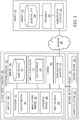
- FIG. 2 shows a block diagram of an alcohol detection device 200.
- Device 200 includes electronics module 210.
- Electronics module 210 includes processor 212, power source 282, memory 214, input/output device 216, camera 280 and communication interface 232.
- Device 210 further includes alcohol detection module 220.
- Alcohol detection module 220 includes a sample collection device 270 and an alcohol sensor 272.
- the illustrated alcohol detection device 210 includes a variety of modules and components within the electronics module 210 and alcohol detection module 220, a device within the scope of the present invention may include a subset of the described modules and components. A device within the scope of the present invention may have additional modules and components. A device within the scope of the present invention may have a varying arrangement of modules and components. For example, the alcohol detection module 220 may be part of electronics module 210.
- Processor 212 may include, for example, one or more general-purpose microprocessors, specially designed processors, application specific integrated circuits (ASIC), field programmable gate arrays (FPGA), a collection of discrete logic, and/or any type of processing device capable of executing the techniques described herein.
- processor 212 (or any other processors described herein) may be described as a computing device.
- memory 214 may be configured to store program instructions (e.g., software instructions) that are executed by processor 212 to carry out the techniques described herein.
- the techniques described herein may be executed by specifically programmed circuitry of processor 212.
- Processor 212 can perform a variety of functions and contain a variety of modules.
- processor 212 may include an image capture module 222, a location module 224, a comparative module 226 and a tamper module 234.
- Image capture module 222 interfaces with camera 280 to capture and process images of the inside of the user's mouth.
- Image capture module 222 may transmit and receive commands to 1) trigger camera 280 to capture an image and 2) perform image processing techniques on a captured image from camera 280 such as calibration, normalization, cropping, classification, feature or pattern extraction, color correction, gray scaling, or projection.
- image processing techniques may be used to place the captured image into a common or standardized format for ease of comparison to other captured images, which will be described in further detail with respect to the operation of the comparative module 226.
- image capture module 222 may receive a captured image from camera 280 that is 540 x 540 pixels and through cropping image processing techniques may reduce the captured image to 320 x 320 pixels. Other image processing may be performed on the image once captured and methods to enhance or modify would be apparent to one of skill in the art.
- Location module 224 captures location information related to the location of the device 200.
- location information may include proximity location or absolute location information or both.
- proximity location information may include information indicating that the device 200 is within a certain proximity of another device. An example of such information occurs when device 200 is tethered through radio frequency (RF) or some other mode of communication to a stationary unit, such as a base station permanently installed in a location such as a person's residence.
- RF radio frequency
- the location module provides proximity location information indicating that the device 200 is within a pre-defined radius of the base station such as described in commonly owned and assigned U.S. Patent No. 6998985 .
- Absolute location information can indicate where device 200 as defined geographically.
- This information can be generated using location technologies such as components receive satellite signals and determine location using, for example, GPS or the Global Navigation Satellite System (GLONASS) such as described in commonly owned and assigned U.S. Patent No. 6,853,304 .
- a location module may use other location technologies such as triangulation using local WiFi signals or other known location technologies to estimate location of the device 200, and thereby the location of the person wearing or using the device.
- Comparative module 226 can be used to compare an image of the inside of a user's mouth captured by camera 280 to a stored image for that user to confirm the user's identity.
- device 200 may also include a second camera configured to capture an image of a user's face while the user is providing a sample to the sample collection device.
- One or both of the captured image from inside of the user's mouth or the captured image of the user's face can be compared with a reference image by comparative module 226 to confirm the identity of the user.
- the reference image may be stored on the device 200 as biometric data 230 in memory 214.
- a captured image whether of the inside of a user's mouth or of a user's face can be transmitted to a remote processing device, such as a server 260, and the server can confirm the identity of the user by comparing the captured images to reference images stored as biometric data 250 in memory 234.
- Tamper module 228 can detect tamper with the device 200.
- tamper module 228 may be used to transmit a signal, such as an infrared signal, through a strap on the device and receive the signal on the other end of the strap such as described in commonly owned and assigned U.S. Patent No. 6853304 . If the signal is not received, the tamper module 228 may send an alert the user interface 218 and / or to a remote server 260 to indicate that device 200 has been tampered with.
- a signal such as an infrared signal
- Tamper module 228 may also detect whether a user is using the correct tube, straw or other mechanism to provide a sample to sample collection device 270 by detecting light that is reflected from device 200, through a straw, tube, or other sample collection device and back to receptors on device 200.
- the use of a reflective sample collection device 270 ensures that the user's mouth is accurately aligned with camera 280, so that camera 280 can capture the desired features within a user's mouth. Further, reflective sample collection device 270 ensures that there is a continuous physical connection between the mouth of the user providing a saliva sample and the camera 280 so that a substitute saliva sample cannot be provided to the device 200 in an attempt to fool the device 200.
- Power source 282 can be used to provide power to any component of device 200 that requires power.
- Power source 282 may be a disposable battery such that device 200 is designed to be disposed of once power source 282 is depleted.
- power source 282 may be a rechargeable battery, such as a lithium-ion or nickel-cadmium battery that may hold its charge for a period of time and may be recharged by a user upon depletion, on a regular schedule or as necessary.
- Power source 282 may also be primarily or ancillary provided by energy harvesting means such as solar, thermal, or electromagnetic.
- device 200 may include circuitry in the form of antennae and capacitors to capture electromagnetic radiation, convert to measurable signals (e.g., current or voltage), and store the signal in a capacitor or super-capacitor device to provide power for the components and modules.
- measurable signals e.g., current or voltage
- Memory 214 is used to store information related to the device 200, the user, and other information necessary for device 200 to adequately monitor the user.
- memory 214 may store biometric data 230 related to a user to whom the device 200 is registered.
- Biometric data 230 may include one or more images of a user's face, oral, and dental characteristics. Facial images may include landmarks or features for identifying a user's face. Position, size, and / or shape of the eyes, nose, cheekbones, lips, and jaw may be used to biometrically identify a user by facial features. Other anatomical features of the face may also by captured and analyzed in the present disclosure such as the shape or location of veins.
- One or more images of the mouth may include position, size, and / or shape of the tongue, soft or hard palate, oropharynx, tonsils, or uvula. Other anatomical features of the mouth may also be captured and analyzed in the present disclosure.
- One or more dental images to identify a user may include position, size, and / or shape of the gingival tissue or teeth.
- Memory 214 may also optionally store temperature data as a scalar or a range of values (e.g., minimum to maximum) associated with the breath or anatomical feature of the user.
- biometric data 230 can be reference images.
- biometric data can be specific reference points that are compared to reference points gleaned from an image captured by device 200 to confirm the identity of a user of device 200.
- Memory 214 may include any volatile or non-volatile storage elements. Examples may include random access memory (RAM) such as synchronous dynamic random access memory (SDRAM), read-only memory (ROM), non-volatile random access memory (NVRAM), electrically erasable programmable read-only memory (EEPROM), and FLASH memory.
- RAM random access memory
- SDRAM synchronous dynamic random access memory
- ROM read-only memory
- NVRAM non-volatile random access memory
- EEPROM electrically erasable programmable read-only memory
- FLASH memory FLASH memory
- Camera 280 may be a small camera integrated into the face of device 200 such that camera 280 is aligned to capture an image the inside of a user's mouth during or before or after a user providing a saliva sample to sample collection device 270. In some embodiments, camera 280 is aligned to capture an image at the end of a tube or straw through which a user is required to provide a sample. Tube or straw can be configured to be securely connected to device such that the misalignment or misuse of the tube or straw is indicative of tamper of the device 200.
- Camera 12 may be Charge Coupled Device (CCD) or Complementary Metal-Oxide Semiconductor (CMOS) varieties, color sensing devices or the like.
- An example of an image sensor for camera 280 is S5K9A1-HD 1/9" 1.4 ⁇ m BSI pixel image sensor available from Samsung of Samsung Town, Seoul, South Korea.
- Alcohol detection module 220 can include a variety of components, including sample collection device 270 and alcohol sensor 272.
- Sample collection device 270 is a device or component that serves as an interface through which a user provides a breath or saliva sample, and / or is a receptacle into which a user provides a breath or saliva sample.
- Sample collection device 270 is mated to alcohol sensor 272 so that alcohol sensor 272 can determine whether the sample provided to or through sample collection device 270 includes indications of alcohol, which may.be used to estimate blood alcohol content (BAC).
- BAC blood alcohol content
- Alcohol sensors 272 that use other techniques to detect the presence of alcohol (i.e., without oxidation) may also be used.
- the alcohol detection module 220 may also include a sensor to record the temperature of the breath sample. Processor 212 compares the recorded temperature to data stored in memory 214 to determine variation upper or below an expected value.
- An example of a temperature sensor for alcohol detection module 270 is LM35DZ LM35 Centigrade Temperature Sensor IC from National Semiconductor of Lewisville, TX.
- Server 260 is an example of a remote server that can be in communication with alcohol detection device 200.
- Server 260 includes memory 234, processor 242 and communication interface 252.
- Server 260 may operate within a local network or be hosted in a Cloud computing environment.
- Communication interface 252 can communicate with device 200 through a variety of types of networks 240, including WiFi, cellular, Bluetooth, Bluetooth low energy, or the like.
- Memory 234 can include a variety of information, such as device history information, enrollment information for a user of device 200, biometric data 250 for a user of device 200, historic location or other device status information, device repair history, and rules or other monitoring restrictions associated with a user of device 200.
- Biometric data 250 may contain the same data as was described for biometric data 230 of the device 200.
- Processor 242 can be used to process information related to device 200. For example, in one embodiment, processor 242 may do comparative analysis, comparing a captured image to a reference image or comparing data mined from a captured image to reference data for a particular user.
- Processor 242 may include, for example, one or more general-purpose microprocessors, specially designed processors, application specific integrated circuits (ASIC), field programmable gate arrays (FPGA), a collection of discrete logic, and/or any type of processing device capable of executing the techniques described herein.
- ASIC application specific integrated circuits
- FPGA field programmable gate arrays
- processor 242 may be described as a computing device.
- memory 234 may be configured to store program instructions (e.g., software instructions) that are executed by processor 242 to carry out the techniques described herein. In other embodiments, the techniques described herein may be executed by specifically programmed circuitry of processor 242.
- Memory 234 may include any volatile or non-volatile storage elements. Examples may include random access memory (RAM) such as synchronous dynamic random access memory (SDRAM), read-only memory (ROM), non-volatile random access memory (NVRAM), electrically erasable programmable read-only memory (EEPROM), and FLASH memory
- RAM random access memory
- SDRAM synchronous dynamic random access memory
- ROM read-only memory
- NVRAM non-volatile random access memory
- EEPROM electrically erasable programmable read-only memory
- device 200 when device 200 detects tamper, indication of alcohol, or any other status or action requiring an alert, device 200 may signal both a local alert by providing such an alert to user interface 218 to be displayed to a user. Device 200 may also, or instead, transmit an alert to server 260 to provide external notification of an incident. External notification may include notification of a monitoring database or monitoring center, emergency health professionals, law enforcement, parole officers or any other designated recipient of an alert or notification.
- Input / output device 216 may include one or more devices configured to input or output information from or to a user or other device.
- the input / output device 216 may present a user interface 218 where a user may configure the operation of or receive instructions from the device 200.
- the user interface 218 may include a display screen for presenting visual information to a user.
- the display screen includes a touch sensitive display.
- a user interface 218 may include one or more different types of devices for presenting information to a user.
- the user interface 218 may include, for example, any number of visual (e.g., display devices, lights, etc.), audible (e.g., one or more speakers), and/or tactile (i.e., buttons) feedback devices.
- the input / output devices 216 may represent one or more of a display screen (e.g., a liquid crystal display or light emitting diode display) and/or a printer (e.g., a printing device or component for outputting instructions to a printing device).
- the input / output device 216 may be configured to accept or receive program instructions (e.g., software instructions) that are executed by the processor 212 to carry out the embodiments described herein.
- Communication interface 232 can communicate with server 260 through a variety of types of networks 240, including WiFi, cellular, Bluetooth, Bluetooth low energy, or the like.
- FIG. 3 is an exemplary reflective tube 300.
- reflective tube may be used to ensure a continuous connection between the mouth of a user providing a sample and the device described herein. Further, it ensures the tube is of the proper dimensions to allow a camera in the device to capture an image of the user's mouth.
- Tube 300 includes several layers including hollow channel 304, interior layer 302, film layer 310 and exterior layer 303. Embedded in film layer 310 are optic inputs306 and optic outputs 308 that are aligned with light sources from the tamper module of an alcohol detection device as described herein.
- the tube is constructed in multiple layers.
- the outer layer is a protective covering made from opaque material, such as high density polyethylene or polyvinyl chloride, to hide the internal construction.
- each fiber optic light guide pipe running parallel to the length of the tube assembly, and arranged in a circular array around the diameter of the tube. These pipes are arranged in such a way that it is not easy to drill a hole from the outer opaque cover to the inside of the tube without passing through at least one fiber optic light guide.
- the ends of each fiber light guide are coated with a metallic film so that light that is injected in the other end of the fiber will reflect back to the source.
- the non-coated end of the fiber is brought to the end of the tube assembly where it is inserted in the alcohol detection module 220.
- LEDs light emitting diodes
- the tube assembly contains a hollow tube extending the length of the tube assembly to allow the user's breath to be sampled by the alcohol detection module 220.
- FIG. 4 is an exemplary flow chart 400 for using a mobile alcohol detection device.
- the device indicates to the user that a test is required.
- the device may provide an indication through an auditory or visual alarm or alert.
- the device may provide a set amount of time in which the user must complete the test.
- the device may instruct or require a user to acknowledge the alarm or alert through means such as pressing a button or providing another response through the user interface.
- the device exposes the sample collection device to the user. This may occur by the device exposing an opening through which it will absorb the user's breath sample.
- the device exposes the sample collection device 270 to the user. This may occur by the device loading a new collection tube into the sampling sensor and then exposing it to the user through an opening in the device. Alternately, the device may present the user with the collection tube through an opening and the user will be required to insert the tube in the sample collection sensor, similar to inserting a straw into opening in the device.
- the device may also include a locking mechanism or electromechanical latch to prevent insertion of the sample collection device 270 until the user is notified to conduct the test.
- the device may absorb the breath sample directly, or through a tube, such as the one illustrated in FIG. 3 .
- step 406 the user inserts a sample collection tube into the device.
- the tube may be inserted so that it is properly aligned with the camera and any other tamper features included in the device.
- step 408 the user blows into the sample collection device, thus providing a breath sample to the alcohol detection module.
- step 410 the camera captures an image of the inside of the user's mouth.
- the alcohol detection module analyzes the breath sample and the device analyzes the image of the user's mouth that was captured by the camera. If the image, or certain features of the image, does not match the stored for the designated user, the device may trigger a local alert or a remote alert indicating tamper.
- the device may also trigger a local alert or a remote alert.
- the alert may be indicative of violation of parole or other alcohol-related restrictions the user is subject to. If an alcohol alert is triggered, the user may be required to go to a location where they must complete a verifying alcohol test.
- FIG. 5 is an exemplary flow chart 500 for detecting tamper with a reflective tube.
- the device emits light on the film layer of the collection tube.
- the light emitted may be from an LED or similar light emitting device, such as a laser, and may be in the visible, infrared (IR), or ultraviolet (UV) spectrum.
- the light may be directed through a lens (e.g., concave or convex) or other focusing / magnifying mechanism into the tube's fiber optic light guides.
- the device detects returned light reflected back from the end of each fiber optic light guide.
- the device monitors for a tamper event.
- a tamper event may include drilling through the side wall of the tube assembly disrupting the ability of a particular fiber optic light guide to reflect light off the metallized end.
- the techniques of this disclosure may be implemented in a wide variety of computer devices, such as servers, laptop computers, desktop computers, notebook computers, tablet computers, hand-held computers, smart phones, and the like. Any components, modules or units have been described to emphasize functional aspects and do not necessarily require realization by different hardware units.
- the techniques described herein may also be implemented in hardware, software, firmware, or any combination thereof. Any features described as modules, units or components may be implemented together in an integrated logic device or separately as discrete but interoperable logic devices. In some cases, various features may be implemented as an integrated circuit device, such as an integrated circuit chip or chipset.
- modules have been described throughout this description, many of which perform unique functions, all the functions of all of the modules may be combined into a single module, or even split into further additional modules.
- the modules described herein are only exemplary and have been described as such for better ease of understanding.
- the techniques may be realized at least in part by a computer-readable medium comprising instructions that, when executed in a processor, performs one or more of the methods described above.
- the computer-readable medium may comprise a tangible computer-readable storage medium and may form part of a computer program product, which may include packaging materials.
- the computer-readable storage medium may comprise random access memory (RAM) such as synchronous dynamic random access memory (SDRAM), read-only memory (ROM), non-volatile random access memory (NVRAM), electrically erasable programmable read-only memory (EEPROM), FLASH memory, magnetic or optical data storage media, and the like.
- RAM random access memory
- SDRAM synchronous dynamic random access memory
- ROM read-only memory
- NVRAM non-volatile random access memory
- EEPROM electrically erasable programmable read-only memory
- FLASH memory magnetic or optical data storage media, and the like.
- the computer-readable storage medium may also comprise a non-volatile storage device, such as a hard-disk, magnetic tape, a compact disk (CD), digital versatile disk (DVD), Bluray disk, holographic data storage media, or other non-volatile storage device.
- a non-volatile storage device such as a hard-disk, magnetic tape, a compact disk (CD), digital versatile disk (DVD), Bluray disk, holographic data storage media, or other non-volatile storage device.
- processor may refer to any of the foregoing structure or any other structure suitable for implementation of the techniques described herein.
- functionality described herein may be provided within dedicated software modules or hardware modules configured for performing the techniques of this disclosure. Even if implemented in software, the techniques may use hardware such as a processor to execute the software, and a memory to store the software. In any such cases, the computers described herein may define a specific machine that is capable of executing the specific functions described herein. Also, the techniques could be fully implemented in one or more circuits or logic elements, which could also be considered a processor.
Landscapes
- Health & Medical Sciences (AREA)
- Life Sciences & Earth Sciences (AREA)
- Engineering & Computer Science (AREA)
- Physics & Mathematics (AREA)
- Biomedical Technology (AREA)
- Molecular Biology (AREA)
- Pathology (AREA)
- Biophysics (AREA)
- General Health & Medical Sciences (AREA)
- Animal Behavior & Ethology (AREA)
- Veterinary Medicine (AREA)
- Public Health (AREA)
- Surgery (AREA)
- Medical Informatics (AREA)
- Heart & Thoracic Surgery (AREA)
- Physiology (AREA)
- Chemical & Material Sciences (AREA)
- Pulmonology (AREA)
- Urology & Nephrology (AREA)
- Analytical Chemistry (AREA)
- Toxicology (AREA)
- Pharmacology & Pharmacy (AREA)
- Immunology (AREA)
- General Physics & Mathematics (AREA)
- Biochemistry (AREA)
- Bioinformatics & Cheminformatics (AREA)
- Medicinal Chemistry (AREA)
- Food Science & Technology (AREA)
- Hematology (AREA)
- Radar, Positioning & Navigation (AREA)
- Oral & Maxillofacial Surgery (AREA)
- Dentistry (AREA)
- Investigating Or Analysing Biological Materials (AREA)
- Telephone Function (AREA)
Description
- The present disclosure relates to the field of alcohol monitoring. More specifically, the present disclosure relates to the field of mobile breath alcohol monitoring.
- Alcohol monitoring plays an important role in a variety of fields, ranging from monitoring the use of alcohol for individuals working in occupations, such as healthcare or transportation, where alcohol and drug testing is a regular event associated with monitoring released offenders with alcohol use restrictions and participants in rehabilitation programs.
- Alcohol presence can be tested through a variety of methods, including testing urine samples, blood samples, transdermal testing and breath testing. Breath testing often includes analyzing saliva included in exhaled breath for indicators of alcohol. Both blood and urine testing can be invasive and present challenges to perform quickly or in a public setting. Transdermal monitoring can be expensive and may result in inadvertent alcohol detection or false positives.
- Breath alcohol testing is commonly used in a multitude of applications because of its convenience and low cost. Typically, breath alcohol testers require a person to blow a sample of breath into a testing device. Within an electrochemical cell, ethanol present in the breath sample is oxidized to acetic acid by the atmospheric reduction of oxygen and converted into an electrical current by a microprocessor contained in a testing device. A person's alcohol usage is determined based upon a comparison between the electrical current calculated from the alcohol content in their breath to predetermined values that are stored in the testing device.
- Breath alcohol testing presents several challenges. For example, with many current breath alcohol testers, there is no way to confirm the location or identity of the individual completing the test with the testing device alone. Further, even with breath alcohol testing devices that may include cameras peripherally connected to the testing device for capturing an image of the person's face, the image is often recorded and visual inspection is used to confirm the individual's identity after the test has concluded. At times, when the identity of a person is verified by an image of their face, the person can substitute a photograph or use another mechanism to tamper with the identification method. An improved breath alcohol testing system would be welcomed.
US publication 2013/021153 to KEAYS dated January 24, 2013 describes a sobriety monitoring system.US publication 2014/1650097 to MOCHIZUKI et al. dated June 19, 2014 describes a breath component measuring device.US publication 2013/035302 to GEMER dated February 7, 2013 describes a mobile remote alcohol monitoring device. - The present disclosure provides both a handheld and a wrist-worn alcohol detection device. The alcohol detection device provides new methods for confirming the identity of the person providing a sample to the alcohol detection device. The present disclosure provides several advantages including, but not limited to, the identification and confirmation of a user's identity without the need for manual or visual inspection in a compact, an integrated device, and concurrently determining the presence of alcohol contained in the breath of the user. Peripherally connected system components, such as cameras or other biometric sensors (i.e., fingerprint), would not be required to authentic or confirm the identity of the user. This minimization of system components reduces the form factor of the testing device, decreases inaccuracies that may be captured or reported, and lessens the probability that the testing device is tampered.
- Specifically, the present disclosure includes a body-worn alcohol detection device according to claim 1. The device includes a housing comprising an electronics module and an alcohol detection module. The device further comprises a strap for securing the housing to a limb of the user.
The electronics module includes a processor and a communication module, and the alcohol detection module includes an alcohol detection sensor, a sample collection device and a biometric camera for capturing an image of the inside of the user's mouth. - In another aspect, the present disclosure includes an alcohol detection device. The device comprises a housing comprising an electronics module and an alcohol detection module. The electronics module includes a processor and a communication module. The alcohol detection module includes an alcohol detection sensor and sample collection device and a biometric camera for capturing an image of the inside of a user's mouth.
- In another aspect, the present disclosure includes a body-worn alcohol detection device. The device includes a housing comprising an electronics module and an alcohol detection module and a strap for securing the housing to a limb of a wearer. The electronics module includes a communication module. The alcohol detection module includes an alcohol detection sensor and a sample collection device. The sample collection device includes at least one light source and at least one light detector.
- The following figures provide illustrations of the present invention. They are intended to further describe and clarify the invention, but not to limit scope of the invention.
-
FIG. 1 is an exemplary mobile alcohol detection device. -
FIG. 2 block diagram of mobile alcohol detection device and a server. -
FIG. 3 is an exemplary reflective tube. -
FIG. 4 is an exemplary flow chart for using a mobile alcohol detection device. -
FIG. 5 is an exemplary flow chart for detecting tamper with a reflective tube. - Like numbers are generally used to refer to like components. The drawings are not to scale and are for illustrative purposes only.
-
FIG. 1 is an exemplary mobilealcohol detection device 100. Mobile alcohol detection devices can take several forms, including handheld and body-worn devices.Device 100 is a body-worn device. More specifically,device 100 is designed to be worn on the wrist of a user.Device 100 includesstrap 102,housing 104,alcohol detection module 106, which includes an alcohol detection sensor, a sample collection device and a biometric camera for capturing an image of the inside of the user's mouth.Device 100 further includes a user interface, including both adisplay 108 andbuttons 110.Display 108 may include one or more different types of devices for presenting information (e.g., instructions to operate device 100) to a user.Display 108 may include any number of visual (e.g., liquid crystal display or light emitting diode) or audible (e.g., one or more speakers) feedback devices.Buttons 110 provide a mechanism to interact withdevice 100 and/or respond to instructions presented on thedisplay 108.Buttons 110 may be physically present ondevice 100 or contained withindisplay 108 through soft or touch interaction. Placement of thealcohol detection module 106,display 108, andbuttons 110 is exemplary and other location configurations or arrangements on themobile alcohol detection 100 are within the scope of the present disclosure. - While
device 100 is shown as a wrist worn device,device 100 can also be a handheld device, or can be configured in any other way consistent with the present disclosure. Handheld device may not include the same components as a wristworn device 100. For example, ahandheld device 100 may not includestrap 102. -
FIG. 2 shows a block diagram of analcohol detection device 200.Device 200 includeselectronics module 210.Electronics module 210 includesprocessor 212,power source 282,memory 214, input/output device 216,camera 280 andcommunication interface 232.Device 210 further includesalcohol detection module 220.Alcohol detection module 220 includes asample collection device 270 and analcohol sensor 272. - While the illustrated
alcohol detection device 210 includes a variety of modules and components within theelectronics module 210 andalcohol detection module 220, a device within the scope of the present invention may include a subset of the described modules and components. A device within the scope of the present invention may have additional modules and components. A device within the scope of the present invention may have a varying arrangement of modules and components. For example, thealcohol detection module 220 may be part ofelectronics module 210. -
Processor 212 may include, for example, one or more general-purpose microprocessors, specially designed processors, application specific integrated circuits (ASIC), field programmable gate arrays (FPGA), a collection of discrete logic, and/or any type of processing device capable of executing the techniques described herein. In some embodiments, processor 212 (or any other processors described herein) may be described as a computing device. In some embodiments,memory 214 may be configured to store program instructions (e.g., software instructions) that are executed byprocessor 212 to carry out the techniques described herein. In other embodiments, the techniques described herein may be executed by specifically programmed circuitry ofprocessor 212.Processor 212 can perform a variety of functions and contain a variety of modules. For example,processor 212 may include animage capture module 222, alocation module 224, a comparative module 226 and atamper module 234. -
Image capture module 222 interfaces withcamera 280 to capture and process images of the inside of the user's mouth.Image capture module 222, as managed by theprocessor 212, may transmit and receive commands to 1)trigger camera 280 to capture an image and 2) perform image processing techniques on a captured image fromcamera 280 such as calibration, normalization, cropping, classification, feature or pattern extraction, color correction, gray scaling, or projection. Various image processing techniques may be used to place the captured image into a common or standardized format for ease of comparison to other captured images, which will be described in further detail with respect to the operation of the comparative module 226. For example,image capture module 222 may receive a captured image fromcamera 280 that is 540 x 540 pixels and through cropping image processing techniques may reduce the captured image to 320 x 320 pixels. Other image processing may be performed on the image once captured and methods to enhance or modify would be apparent to one of skill in the art. -
Location module 224 captures location information related to the location of thedevice 200. Such location information may include proximity location or absolute location information or both. For example, proximity location information may include information indicating that thedevice 200 is within a certain proximity of another device. An example of such information occurs whendevice 200 is tethered through radio frequency (RF) or some other mode of communication to a stationary unit, such as a base station permanently installed in a location such as a person's residence. Whendevice 200 is in communication with the base unit, the location module provides proximity location information indicating that thedevice 200 is within a pre-defined radius of the base station such as described in commonly owned and assignedU.S. Patent No. 6998985 . Absolute location information can indicate wheredevice 200 as defined geographically. This information can be generated using location technologies such as components receive satellite signals and determine location using, for example, GPS or the Global Navigation Satellite System (GLONASS) such as described in commonly owned and assignedU.S. Patent No. 6,853,304 . A location module may use other location technologies such as triangulation using local WiFi signals or other known location technologies to estimate location of thedevice 200, and thereby the location of the person wearing or using the device. - Comparative module 226 can be used to compare an image of the inside of a user's mouth captured by
camera 280 to a stored image for that user to confirm the user's identity. In some embodiments,device 200 may also include a second camera configured to capture an image of a user's face while the user is providing a sample to the sample collection device. One or both of the captured image from inside of the user's mouth or the captured image of the user's face can be compared with a reference image by comparative module 226 to confirm the identity of the user. In one example, the reference image may be stored on thedevice 200 asbiometric data 230 inmemory 214. In an alternate embodiment, a captured image, whether of the inside of a user's mouth or of a user's face can be transmitted to a remote processing device, such as aserver 260, and the server can confirm the identity of the user by comparing the captured images to reference images stored asbiometric data 250 inmemory 234. - Tamper module 228 can detect tamper with the
device 200. For example, tamper module 228 may be used to transmit a signal, such as an infrared signal, through a strap on the device and receive the signal on the other end of the strap such as described in commonly owned and assignedU.S. Patent No. 6853304 . If the signal is not received, the tamper module 228 may send an alert theuser interface 218 and / or to aremote server 260 to indicate thatdevice 200 has been tampered with. Tamper module 228 may also detect whether a user is using the correct tube, straw or other mechanism to provide a sample to samplecollection device 270 by detecting light that is reflected fromdevice 200, through a straw, tube, or other sample collection device and back to receptors ondevice 200. The use of a reflectivesample collection device 270 ensures that the user's mouth is accurately aligned withcamera 280, so thatcamera 280 can capture the desired features within a user's mouth. Further, reflectivesample collection device 270 ensures that there is a continuous physical connection between the mouth of the user providing a saliva sample and thecamera 280 so that a substitute saliva sample cannot be provided to thedevice 200 in an attempt to fool thedevice 200. -
Power source 282 can be used to provide power to any component ofdevice 200 that requires power.Power source 282 may be a disposable battery such thatdevice 200 is designed to be disposed of oncepower source 282 is depleted. In another embodiment,power source 282 may be a rechargeable battery, such as a lithium-ion or nickel-cadmium battery that may hold its charge for a period of time and may be recharged by a user upon depletion, on a regular schedule or as necessary.Power source 282 may also be primarily or ancillary provided by energy harvesting means such as solar, thermal, or electromagnetic. As an example,device 200 may include circuitry in the form of antennae and capacitors to capture electromagnetic radiation, convert to measurable signals (e.g., current or voltage), and store the signal in a capacitor or super-capacitor device to provide power for the components and modules. -
Memory 214 is used to store information related to thedevice 200, the user, and other information necessary fordevice 200 to adequately monitor the user. For example,memory 214 may storebiometric data 230 related to a user to whom thedevice 200 is registered.Biometric data 230 may include one or more images of a user's face, oral, and dental characteristics. Facial images may include landmarks or features for identifying a user's face. Position, size, and / or shape of the eyes, nose, cheekbones, lips, and jaw may be used to biometrically identify a user by facial features. Other anatomical features of the face may also by captured and analyzed in the present disclosure such as the shape or location of veins. One or more images of the mouth may include position, size, and / or shape of the tongue, soft or hard palate, oropharynx, tonsils, or uvula. Other anatomical features of the mouth may also be captured and analyzed in the present disclosure. One or more dental images to identify a user may include position, size, and / or shape of the gingival tissue or teeth.Memory 214 may also optionally store temperature data as a scalar or a range of values (e.g., minimum to maximum) associated with the breath or anatomical feature of the user. Suchbiometric data 230 can be reference images. In another embodiment, biometric data can be specific reference points that are compared to reference points gleaned from an image captured bydevice 200 to confirm the identity of a user ofdevice 200.Memory 214 may include any volatile or non-volatile storage elements. Examples may include random access memory (RAM) such as synchronous dynamic random access memory (SDRAM), read-only memory (ROM), non-volatile random access memory (NVRAM), electrically erasable programmable read-only memory (EEPROM), and FLASH memory. -
Camera 280 may be a small camera integrated into the face ofdevice 200 such thatcamera 280 is aligned to capture an image the inside of a user's mouth during or before or after a user providing a saliva sample to samplecollection device 270. In some embodiments,camera 280 is aligned to capture an image at the end of a tube or straw through which a user is required to provide a sample. Tube or straw can be configured to be securely connected to device such that the misalignment or misuse of the tube or straw is indicative of tamper of thedevice 200. Camera 12 may be Charge Coupled Device (CCD) or Complementary Metal-Oxide Semiconductor (CMOS) varieties, color sensing devices or the like. An example of an image sensor forcamera 280 is S5K9A1-HD 1/9" 1.4µm BSI pixel image sensor available from Samsung of Samsung Town, Seoul, South Korea. -
Alcohol detection module 220 can include a variety of components, includingsample collection device 270 andalcohol sensor 272.Sample collection device 270 is a device or component that serves as an interface through which a user provides a breath or saliva sample, and / or is a receptacle into which a user provides a breath or saliva sample.Sample collection device 270 is mated toalcohol sensor 272 so thatalcohol sensor 272 can determine whether the sample provided to or throughsample collection device 270 includes indications of alcohol, which may.be used to estimate blood alcohol content (BAC). When a user provides a breath sample through the tube to thesample collection device 270 any ethanol present in the breath is oxidized to acetic acid at the anode of thealcohol sensor 272. At the cathode of thealcohol sensor 272 atmospheric oxygen is reduced, with an overall reaction of oxidation of ethanol into acetic acid and water. The reaction produces an electrical current which is measured by thealcohol sensor 272 and sent to theprocessor 212.Processor 212 compares the measured electrical current to data stored inmemory 214 to determine and / or estimate the BAC of thedevice 200 user.Alcohol sensors 272 that use other techniques to detect the presence of alcohol (i.e., without oxidation) may also be used. Thealcohol detection module 220 may also include a sensor to record the temperature of the breath sample.Processor 212 compares the recorded temperature to data stored inmemory 214 to determine variation upper or below an expected value. An example of a temperature sensor foralcohol detection module 270 is LM35DZ LM35 Centigrade Temperature Sensor IC from National Semiconductor of Lewisville, TX. -
Server 260 is an example of a remote server that can be in communication withalcohol detection device 200.Server 260 includesmemory 234,processor 242 andcommunication interface 252.Server 260 may operate within a local network or be hosted in a Cloud computing environment.Communication interface 252 can communicate withdevice 200 through a variety of types ofnetworks 240, including WiFi, cellular, Bluetooth, Bluetooth low energy, or the like.Memory 234 can include a variety of information, such as device history information, enrollment information for a user ofdevice 200,biometric data 250 for a user ofdevice 200, historic location or other device status information, device repair history, and rules or other monitoring restrictions associated with a user ofdevice 200.Biometric data 250 may contain the same data as was described forbiometric data 230 of thedevice 200.Processor 242 can be used to process information related todevice 200. For example, in one embodiment,processor 242 may do comparative analysis, comparing a captured image to a reference image or comparing data mined from a captured image to reference data for a particular user.Processor 242 may include, for example, one or more general-purpose microprocessors, specially designed processors, application specific integrated circuits (ASIC), field programmable gate arrays (FPGA), a collection of discrete logic, and/or any type of processing device capable of executing the techniques described herein. In some embodiments, processor 242 (or any other processors described herein) may be described as a computing device. In some embodiments,memory 234 may be configured to store program instructions (e.g., software instructions) that are executed byprocessor 242 to carry out the techniques described herein. In other embodiments, the techniques described herein may be executed by specifically programmed circuitry ofprocessor 242.Memory 234 may include any volatile or non-volatile storage elements. Examples may include random access memory (RAM) such as synchronous dynamic random access memory (SDRAM), read-only memory (ROM), non-volatile random access memory (NVRAM), electrically erasable programmable read-only memory (EEPROM), and FLASH memory - In some configurations, when
device 200 detects tamper, indication of alcohol, or any other status or action requiring an alert,device 200 may signal both a local alert by providing such an alert touser interface 218 to be displayed to a user.Device 200 may also, or instead, transmit an alert toserver 260 to provide external notification of an incident. External notification may include notification of a monitoring database or monitoring center, emergency health professionals, law enforcement, parole officers or any other designated recipient of an alert or notification. - Input /
output device 216 may include one or more devices configured to input or output information from or to a user or other device. In some embodiments, the input /output device 216 may present auser interface 218 where a user may configure the operation of or receive instructions from thedevice 200. For example, theuser interface 218 may include a display screen for presenting visual information to a user. In some embodiments, the display screen includes a touch sensitive display. In some embodiments, auser interface 218 may include one or more different types of devices for presenting information to a user. Theuser interface 218 may include, for example, any number of visual (e.g., display devices, lights, etc.), audible (e.g., one or more speakers), and/or tactile (i.e., buttons) feedback devices. In some embodiments, the input /output devices 216 may represent one or more of a display screen (e.g., a liquid crystal display or light emitting diode display) and/or a printer (e.g., a printing device or component for outputting instructions to a printing device). In some embodiments, the input /output device 216 may be configured to accept or receive program instructions (e.g., software instructions) that are executed by theprocessor 212 to carry out the embodiments described herein. -
Communication interface 232 can communicate withserver 260 through a variety of types ofnetworks 240, including WiFi, cellular, Bluetooth, Bluetooth low energy, or the like. -
FIG. 3 is an exemplaryreflective tube 300. In some embodiments, reflective tube may be used to ensure a continuous connection between the mouth of a user providing a sample and the device described herein. Further, it ensures the tube is of the proper dimensions to allow a camera in the device to capture an image of the user's mouth.Tube 300 includes several layers includinghollow channel 304,interior layer 302,film layer 310 andexterior layer 303. Embedded infilm layer 310 are optic inputs306 andoptic outputs 308 that are aligned with light sources from the tamper module of an alcohol detection device as described herein. The tube is constructed in multiple layers. The outer layer is a protective covering made from opaque material, such as high density polyethylene or polyvinyl chloride, to hide the internal construction. Inside the outer layer are multiple fiber optic light guide pipes running parallel to the length of the tube assembly, and arranged in a circular array around the diameter of the tube. These pipes are arranged in such a way that it is not easy to drill a hole from the outer opaque cover to the inside of the tube without passing through at least one fiber optic light guide. The ends of each fiber light guide are coated with a metallic film so that light that is injected in the other end of the fiber will reflect back to the source. The non-coated end of the fiber is brought to the end of the tube assembly where it is inserted in thealcohol detection module 220. In this way, light emitting diodes (LEDs) can inject light into each fiber and the amount oflight reflected back may be measured determining if someone has tampered with the tube by drilling a hole into the tube and disrupting the light reflectance of one of the fibers. Inside the ring of fiber optic light guides is another fiber optic strand used to image the inside of the user's mouth. The pipe extends the length of the tube and is fitted with a lens at each end to allow a camera in thealcohol detection module 220 to receive an image from the other end of the tube inserted in the user's mouth. Finally, the tube assembly contains a hollow tube extending the length of the tube assembly to allow the user's breath to be sampled by thealcohol detection module 220. -
FIG. 4 is anexemplary flow chart 400 for using a mobile alcohol detection device. Instep 402, the device indicates to the user that a test is required. The device may provide an indication through an auditory or visual alarm or alert. The device may provide a set amount of time in which the user must complete the test. In some instances, the device may instruct or require a user to acknowledge the alarm or alert through means such as pressing a button or providing another response through the user interface. - In
step 404, the device exposes the sample collection device to the user. This may occur by the device exposing an opening through which it will absorb the user's breath sample. The device exposes thesample collection device 270 to the user. This may occur by the device loading a new collection tube into the sampling sensor and then exposing it to the user through an opening in the device. Alternately, the device may present the user with the collection tube through an opening and the user will be required to insert the tube in the sample collection sensor, similar to inserting a straw into opening in the device. The device may also include a locking mechanism or electromechanical latch to prevent insertion of thesample collection device 270 until the user is notified to conduct the test. The device may absorb the breath sample directly, or through a tube, such as the one illustrated inFIG. 3 . - In
step 406, the user inserts a sample collection tube into the device. The tube may be inserted so that it is properly aligned with the camera and any other tamper features included in the device. - In
step 408, the user blows into the sample collection device, thus providing a breath sample to the alcohol detection module. - At or near the same time as
step 408, instep 410, the camera captures an image of the inside of the user's mouth. - In
step 412, the alcohol detection module analyzes the breath sample and the device analyzes the image of the user's mouth that was captured by the camera. If the image, or certain features of the image, does not match the stored for the designated user, the device may trigger a local alert or a remote alert indicating tamper. - If the alcohol detection module detects indications of alcohol in the breath sample, the device may also trigger a local alert or a remote alert. The alert may be indicative of violation of parole or other alcohol-related restrictions the user is subject to. If an alcohol alert is triggered, the user may be required to go to a location where they must complete a verifying alcohol test.
-
FIG. 5 is anexemplary flow chart 500 for detecting tamper with a reflective tube. Instep 502, the device emits light on the film layer of the collection tube. The light emitted may be from an LED or similar light emitting device, such as a laser, and may be in the visible, infrared (IR), or ultraviolet (UV) spectrum. The light may be directed through a lens (e.g., concave or convex) or other focusing / magnifying mechanism into the tube's fiber optic light guides. Instep 504, the device detects returned light reflected back from the end of each fiber optic light guide. Instep 506, the device monitors for a tamper event. A tamper event may include drilling through the side wall of the tube assembly disrupting the ability of a particular fiber optic light guide to reflect light off the metallized end. - The techniques of this disclosure may be implemented in a wide variety of computer devices, such as servers, laptop computers, desktop computers, notebook computers, tablet computers, hand-held computers, smart phones, and the like. Any components, modules or units have been described to emphasize functional aspects and do not necessarily require realization by different hardware units. The techniques described herein may also be implemented in hardware, software, firmware, or any combination thereof. Any features described as modules, units or components may be implemented together in an integrated logic device or separately as discrete but interoperable logic devices. In some cases, various features may be implemented as an integrated circuit device, such as an integrated circuit chip or chipset. Additionally, although a number of distinct modules have been described throughout this description, many of which perform unique functions, all the functions of all of the modules may be combined into a single module, or even split into further additional modules. The modules described herein are only exemplary and have been described as such for better ease of understanding.
- If implemented in software, the techniques may be realized at least in part by a computer-readable medium comprising instructions that, when executed in a processor, performs one or more of the methods described above. The computer-readable medium may comprise a tangible computer-readable storage medium and may form part of a computer program product, which may include packaging materials. The computer-readable storage medium may comprise random access memory (RAM) such as synchronous dynamic random access memory (SDRAM), read-only memory (ROM), non-volatile random access memory (NVRAM), electrically erasable programmable read-only memory (EEPROM), FLASH memory, magnetic or optical data storage media, and the like. The computer-readable storage medium may also comprise a non-volatile storage device, such as a hard-disk, magnetic tape, a compact disk (CD), digital versatile disk (DVD), Bluray disk, holographic data storage media, or other non-volatile storage device.
- The term "processor," as used herein may refer to any of the foregoing structure or any other structure suitable for implementation of the techniques described herein. In addition, in some aspects, the functionality described herein may be provided within dedicated software modules or hardware modules configured for performing the techniques of this disclosure. Even if implemented in software, the techniques may use hardware such as a processor to execute the software, and a memory to store the software. In any such cases, the computers described herein may define a specific machine that is capable of executing the specific functions described herein. Also, the techniques could be fully implemented in one or more circuits or logic elements, which could also be considered a processor.
- Variations on the present disclosure will be apparent to one of skill in the art upon reading the present disclosure. For example, a variety of electronic components may be used as within the device. A variety of films and constructions for the tube may also be used consistent with the present invention. The present invention is defined solely by the appended claims.
Claims (13)
- A body-worn alcohol detection device (100) comprising:a housing (104) comprising an electronics module (210) and an alcohol detection module (220);a strap (102) for securing the housing (104) to a limb of a user;wherein the electronics module (210) includes a processor (212), a communication module (232) and a biometric camera (280) for capturing an image of the inside of the user's mouth; andwherein the alcohol detection module (220) includes an alcohol detection sensor (272) and a sample collection device (270); andwherein the device (100) further comprises a reflective tube (300) to ensure a continuous connection between the user's mouth and the alcohol detection device (100);wherein the reflective tube (300) includes several layers including an exterior layer (303), a film layer (310) and an interior layer (302) enclosing a hollow channel (304);wherein the film layer (310) comprises multiple fiber optic light guide pipes (306, 308) that are aligned with light sources from a tamper module of the body-worn alcohol detection device (100) and that run parallel to a length of the reflective tube (300) and are arranged in a circular array around a diameter of the tube (300).
- The device (100) of claim 1, wherein the strap (102) comprises a tamper detection feature.
- The device (100) of claim 1, wherein the electronics module (210) further includes a location module (224).
- The device (100) of claim 1, wherein the electronics module (210) further includes a rechargeable battery (282).
- The device (100) of claim 1, wherein the device (100) is configured to transmit the captured image to a remote processing device (260) for comparing the captured image particularly stored as biometric data (250) in memory (234) with a reference image to confirm the identity of the user.
- The device (100) of claim 1, wherein the device (100) is configured to compare the captured image with the reference image by a comparative model (226) of the device (100).
- The device (100) of claim 1, wherein the device (100) further comprises a user interface (218) to alert the user to provide a sample to the device (100).
- The device (100) of claim 1, wherein the device (100) is configured to receive an alert from a central monitoring system to alert a user to provide a sample to the device (100) through at least one of the following communication means: SMS message, telephone, or email.
- The device (100) of claim 1, wherein the communication module (232) is configured to report results from the alcohol detection sensor (272) to a central monitoring system or designated monitoring officer.
- The device (100) of claim 1, wherein the device (100) further comprises an exterior camera and wherein the exterior camera is positioned to take a picture of at least a portion of the user's face.
- The device (100) of claim 1, wherein the exterior layer (303) comprises a protective covering made from an opaque material to hide internal construction of the reflective tube (300).
- The device (100) of claim 1, wherein ends of each fiber light guide pipes (306, 308) are coated with a metallic film so that light that is injected from a light source in another end of the fiber light guide pipes (306, 308) will reflect back to the light source to detect tampering.
- The device (100) of claim 1, wherein some fiber optic light guide pipes (306, 308) are fitted with a lens at each end to receive an image of the user's mouth with the biometric camera (280).
Applications Claiming Priority (2)
| Application Number | Priority Date | Filing Date | Title |
|---|---|---|---|
| US201562131378P | 2015-03-11 | 2015-03-11 | |
| PCT/US2016/020855 WO2016144738A1 (en) | 2015-03-11 | 2016-03-04 | Wrist worn mobile alcohol and offender monitoring system |
Publications (2)
| Publication Number | Publication Date |
|---|---|
| EP3268738A1 EP3268738A1 (en) | 2018-01-17 |
| EP3268738B1 true EP3268738B1 (en) | 2019-10-02 |
Family
ID=55543107
Family Applications (1)
| Application Number | Title | Priority Date | Filing Date |
|---|---|---|---|
| EP16710586.5A Active EP3268738B1 (en) | 2015-03-11 | 2016-03-04 | Wrist worn mobile alcohol and offender monitoring system |
Country Status (6)
| Country | Link |
|---|---|
| US (1) | US10966633B2 (en) |
| EP (1) | EP3268738B1 (en) |
| BR (1) | BR112017019402A2 (en) |
| CA (1) | CA2979198A1 (en) |
| ES (1) | ES2764131T3 (en) |
| WO (1) | WO2016144738A1 (en) |
Families Citing this family (15)
| Publication number | Priority date | Publication date | Assignee | Title |
|---|---|---|---|---|
| US9192334B2 (en) | 2013-01-31 | 2015-11-24 | KHN Solutions, Inc. | Method and system for monitoring intoxication |
| US9788772B2 (en) | 2013-01-31 | 2017-10-17 | KHN Solutions, Inc. | Wearable system and method for monitoring intoxication |
| US10604011B2 (en) | 2015-10-13 | 2020-03-31 | Consumer Safety Technology, Llc | Networked intoxication vehicle immobilization |
| US11324449B2 (en) * | 2018-03-22 | 2022-05-10 | KHN Solutions, Inc. | Method and system for transdermal alcohol monitoring |
| US11006895B2 (en) | 2018-03-22 | 2021-05-18 | KHN Solutions, Inc. | Method and system for transdermal alcohol monitoring |
| US11147490B2 (en) | 2018-09-25 | 2021-10-19 | Rsc Associates, Inc. | Monitoring devices, systems, and methods for detecting wetness in a garment |
| WO2021216996A1 (en) | 2020-04-24 | 2021-10-28 | Sobr Safe, Inc. | Noninvasive transdermal alcohol screening system |
| US11169096B1 (en) * | 2020-06-09 | 2021-11-09 | Cell Detect, Inc. | Body-worn device with tamper detection, dirt alerting and dirt compensation |
| KR102399150B1 (en) * | 2020-09-08 | 2022-05-17 | 이경미 | Wearable Device and Driving Method thereof |
| CA3197329A1 (en) * | 2020-11-03 | 2022-05-12 | Katia BENSON | Wearable data collection device with non-invasive sensing |
| US12458283B2 (en) * | 2021-01-12 | 2025-11-04 | Khn Solutions, Llc | Method and system for remote transdermal alcohol monitoring |
| US20220240849A1 (en) * | 2021-01-29 | 2022-08-04 | Cade Wolfram Spector | Wearable devices equipped with blood alcohol content sample analyzer, indicative led signals, and bluetooth capabilities |
| US12311759B1 (en) | 2022-02-02 | 2025-05-27 | Consumer Safety Technology, Llc | Wireless vehicle interface for immobilization system |
| US20240285232A1 (en) * | 2023-02-27 | 2024-08-29 | Tracklet Inc. | Device and software application for detecting blood alcohol content |
| US12343133B1 (en) | 2023-10-27 | 2025-07-01 | Khn Solutions, Llc | Method and system for detecting and maintaining performance of an alcohol sensing device |
Family Cites Families (11)
| Publication number | Priority date | Publication date | Assignee | Title |
|---|---|---|---|---|
| US4809810A (en) * | 1986-05-01 | 1989-03-07 | Autosense Corporation | Breath alcohol analyzer |
| US20090182216A1 (en) * | 2008-01-14 | 2009-07-16 | Roushey Iii William James | Moisture control in a transdermal blood alcohol monitor |
| EP2237034B1 (en) * | 2009-04-03 | 2013-07-24 | Dräger Safety AG & Co. KGaA | Device and method for recognising the correct usage of an alcohol measuring device |
| US8707758B2 (en) * | 2009-10-02 | 2014-04-29 | Soberlink, Inc. | Sobriety monitoring system |
| US9417232B2 (en) * | 2009-10-02 | 2016-08-16 | Bi Mobile Breath, Inc. | Sobriety monitoring system |
| US20130035602A1 (en) * | 2011-08-04 | 2013-02-07 | 3M Innovative Properties Company | Mobile remote alcohol monotoring device |
| US9241661B2 (en) * | 2012-09-17 | 2016-01-26 | TraceX, Inc. | Apparatus and method for extra-corporal chemical detection and monitoring |
| US20140165697A1 (en) | 2012-12-17 | 2014-06-19 | Tanita Corporation | Mouthpiece of breath component measuring device, breath component measuring assembly, breath component measuring device, and breath component measuring system |
| US20140365142A1 (en) | 2013-06-11 | 2014-12-11 | Antimatter Research, Inc. | Wearable Blood Alcohol Measuring Device |
| EP2816352B1 (en) | 2013-06-21 | 2016-12-28 | Sensirion AG | Concentration measurements with a mobile device |
| US20150084774A1 (en) * | 2013-09-26 | 2015-03-26 | Mark Henry Wojcik | Remote breath alcohol monitor |
-
2016
- 2016-03-04 WO PCT/US2016/020855 patent/WO2016144738A1/en not_active Ceased
- 2016-03-04 ES ES16710586T patent/ES2764131T3/en active Active
- 2016-03-04 EP EP16710586.5A patent/EP3268738B1/en active Active
- 2016-03-04 US US15/557,319 patent/US10966633B2/en active Active
- 2016-03-04 CA CA2979198A patent/CA2979198A1/en not_active Abandoned
- 2016-03-04 BR BR112017019402-3A patent/BR112017019402A2/en not_active Application Discontinuation
Non-Patent Citations (1)
| Title |
|---|
| None * |
Also Published As
| Publication number | Publication date |
|---|---|
| BR112017019402A2 (en) | 2018-05-02 |
| EP3268738A1 (en) | 2018-01-17 |
| CA2979198A1 (en) | 2016-09-15 |
| US20180049668A1 (en) | 2018-02-22 |
| ES2764131T3 (en) | 2020-06-02 |
| WO2016144738A1 (en) | 2016-09-15 |
| US10966633B2 (en) | 2021-04-06 |
Similar Documents
| Publication | Publication Date | Title |
|---|---|---|
| US10966633B2 (en) | Wrist worn mobile alcohol and offender monitoring system | |
| US20230200727A1 (en) | Sobriety monitoring system | |
| US20240385171A1 (en) | Sobriety monitoring system | |
| RU2578023C2 (en) | Portable diagnostic unit and method for using it with electronic device and diagnostic cartridge in instant diagnostic tests | |
| US20120075094A1 (en) | Sobriety Monitoring System | |
| US8381573B2 (en) | Sobriety monitoring system | |
| US9915644B2 (en) | Method and system for remotely monitoring intoxication | |
| US20150051502A1 (en) | Breath analyzer, system, and computer program for authenticating, preserving, and presenting breath analysis data | |
| US9922508B2 (en) | Bioresistive-fingerprint based sobriety monitoring system | |
| US11701007B2 (en) | Systems and methods for biometric tamper detection | |
| US10557844B2 (en) | Bioresistive-fingerprint based sobriety monitoring system | |
| WO2016061533A1 (en) | Breath analyzer, system, and computer program for authenticating, preserving, and presenting breath analysis data | |
| CN108267583A (en) | Portable fast screen external detection system | |
| WO2015009240A1 (en) | Mobile integrated device and system for identifying potential infected subjects and managing health data and method of operation | |
| TWI612306B (en) | Portable point of care testing (poct) system | |
| US20220057525A1 (en) | Identification device | |
| KR20180002138A (en) | Device for detecting portent symptom of illness | |
| CN118285113A (en) | Image processing device, terminal and monitoring method |
Legal Events
| Date | Code | Title | Description |
|---|---|---|---|
| STAA | Information on the status of an ep patent application or granted ep patent |
Free format text: STATUS: THE INTERNATIONAL PUBLICATION HAS BEEN MADE |
|
| PUAI | Public reference made under article 153(3) epc to a published international application that has entered the european phase |
Free format text: ORIGINAL CODE: 0009012 |
|
| STAA | Information on the status of an ep patent application or granted ep patent |
Free format text: STATUS: REQUEST FOR EXAMINATION WAS MADE |
|
| 17P | Request for examination filed |
Effective date: 20170912 |
|
| AK | Designated contracting states |
Kind code of ref document: A1 Designated state(s): AL AT BE BG CH CY CZ DE DK EE ES FI FR GB GR HR HU IE IS IT LI LT LU LV MC MK MT NL NO PL PT RO RS SE SI SK SM TR |
|
| AX | Request for extension of the european patent |
Extension state: BA ME |
|
| DAV | Request for validation of the european patent (deleted) | ||
| DAX | Request for extension of the european patent (deleted) | ||
| STAA | Information on the status of an ep patent application or granted ep patent |
Free format text: STATUS: EXAMINATION IS IN PROGRESS |
|
| 17Q | First examination report despatched |
Effective date: 20181116 |
|
| RAP1 | Party data changed (applicant data changed or rights of an application transferred) |
Owner name: 3M ELECTRONIC MONITORING LTD. |
|
| GRAP | Despatch of communication of intention to grant a patent |
Free format text: ORIGINAL CODE: EPIDOSNIGR1 |
|
| STAA | Information on the status of an ep patent application or granted ep patent |
Free format text: STATUS: GRANT OF PATENT IS INTENDED |
|
| INTG | Intention to grant announced |
Effective date: 20190627 |
|
| GRAS | Grant fee paid |
Free format text: ORIGINAL CODE: EPIDOSNIGR3 |
|
| GRAA | (expected) grant |
Free format text: ORIGINAL CODE: 0009210 |
|
| STAA | Information on the status of an ep patent application or granted ep patent |
Free format text: STATUS: THE PATENT HAS BEEN GRANTED |
|
| AK | Designated contracting states |
Kind code of ref document: B1 Designated state(s): AL AT BE BG CH CY CZ DE DK EE ES FI FR GB GR HR HU IE IS IT LI LT LU LV MC MK MT NL NO PL PT RO RS SE SI SK SM TR |
|
| REG | Reference to a national code |
Ref country code: GB Ref legal event code: FG4D |
|
| REG | Reference to a national code |
Ref country code: CH Ref legal event code: EP Ref country code: AT Ref legal event code: REF Ref document number: 1186761 Country of ref document: AT Kind code of ref document: T Effective date: 20191015 |
|
| REG | Reference to a national code |
Ref country code: DE Ref legal event code: R096 Ref document number: 602016021643 Country of ref document: DE |
|
| REG | Reference to a national code |
Ref country code: IE Ref legal event code: FG4D |
|
| REG | Reference to a national code |
Ref country code: NL Ref legal event code: MP Effective date: 20191002 |
|
| REG | Reference to a national code |
Ref country code: LT Ref legal event code: MG4D |
|
| REG | Reference to a national code |
Ref country code: AT Ref legal event code: MK05 Ref document number: 1186761 Country of ref document: AT Kind code of ref document: T Effective date: 20191002 |
|
| PG25 | Lapsed in a contracting state [announced via postgrant information from national office to epo] |
Ref country code: NL Free format text: LAPSE BECAUSE OF FAILURE TO SUBMIT A TRANSLATION OF THE DESCRIPTION OR TO PAY THE FEE WITHIN THE PRESCRIBED TIME-LIMIT Effective date: 20191002 Ref country code: AT Free format text: LAPSE BECAUSE OF FAILURE TO SUBMIT A TRANSLATION OF THE DESCRIPTION OR TO PAY THE FEE WITHIN THE PRESCRIBED TIME-LIMIT Effective date: 20191002 Ref country code: BG Free format text: LAPSE BECAUSE OF FAILURE TO SUBMIT A TRANSLATION OF THE DESCRIPTION OR TO PAY THE FEE WITHIN THE PRESCRIBED TIME-LIMIT Effective date: 20200102 Ref country code: NO Free format text: LAPSE BECAUSE OF FAILURE TO SUBMIT A TRANSLATION OF THE DESCRIPTION OR TO PAY THE FEE WITHIN THE PRESCRIBED TIME-LIMIT Effective date: 20200102 Ref country code: FI Free format text: LAPSE BECAUSE OF FAILURE TO SUBMIT A TRANSLATION OF THE DESCRIPTION OR TO PAY THE FEE WITHIN THE PRESCRIBED TIME-LIMIT Effective date: 20191002 Ref country code: PT Free format text: LAPSE BECAUSE OF FAILURE TO SUBMIT A TRANSLATION OF THE DESCRIPTION OR TO PAY THE FEE WITHIN THE PRESCRIBED TIME-LIMIT Effective date: 20200203 Ref country code: LT Free format text: LAPSE BECAUSE OF FAILURE TO SUBMIT A TRANSLATION OF THE DESCRIPTION OR TO PAY THE FEE WITHIN THE PRESCRIBED TIME-LIMIT Effective date: 20191002 Ref country code: PL Free format text: LAPSE BECAUSE OF FAILURE TO SUBMIT A TRANSLATION OF THE DESCRIPTION OR TO PAY THE FEE WITHIN THE PRESCRIBED TIME-LIMIT Effective date: 20191002 Ref country code: GR Free format text: LAPSE BECAUSE OF FAILURE TO SUBMIT A TRANSLATION OF THE DESCRIPTION OR TO PAY THE FEE WITHIN THE PRESCRIBED TIME-LIMIT Effective date: 20200103 Ref country code: SE Free format text: LAPSE BECAUSE OF FAILURE TO SUBMIT A TRANSLATION OF THE DESCRIPTION OR TO PAY THE FEE WITHIN THE PRESCRIBED TIME-LIMIT Effective date: 20191002 Ref country code: LV Free format text: LAPSE BECAUSE OF FAILURE TO SUBMIT A TRANSLATION OF THE DESCRIPTION OR TO PAY THE FEE WITHIN THE PRESCRIBED TIME-LIMIT Effective date: 20191002 |
|
| PG25 | Lapsed in a contracting state [announced via postgrant information from national office to epo] |
Ref country code: HR Free format text: LAPSE BECAUSE OF FAILURE TO SUBMIT A TRANSLATION OF THE DESCRIPTION OR TO PAY THE FEE WITHIN THE PRESCRIBED TIME-LIMIT Effective date: 20191002 Ref country code: RS Free format text: LAPSE BECAUSE OF FAILURE TO SUBMIT A TRANSLATION OF THE DESCRIPTION OR TO PAY THE FEE WITHIN THE PRESCRIBED TIME-LIMIT Effective date: 20191002 Ref country code: IS Free format text: LAPSE BECAUSE OF FAILURE TO SUBMIT A TRANSLATION OF THE DESCRIPTION OR TO PAY THE FEE WITHIN THE PRESCRIBED TIME-LIMIT Effective date: 20200224 Ref country code: CZ Free format text: LAPSE BECAUSE OF FAILURE TO SUBMIT A TRANSLATION OF THE DESCRIPTION OR TO PAY THE FEE WITHIN THE PRESCRIBED TIME-LIMIT Effective date: 20191002 |
|
| REG | Reference to a national code |
Ref country code: ES Ref legal event code: FG2A Ref document number: 2764131 Country of ref document: ES Kind code of ref document: T3 Effective date: 20200602 |
|
| PG25 | Lapsed in a contracting state [announced via postgrant information from national office to epo] |
Ref country code: AL Free format text: LAPSE BECAUSE OF FAILURE TO SUBMIT A TRANSLATION OF THE DESCRIPTION OR TO PAY THE FEE WITHIN THE PRESCRIBED TIME-LIMIT Effective date: 20191002 |
|
| REG | Reference to a national code |
Ref country code: DE Ref legal event code: R097 Ref document number: 602016021643 Country of ref document: DE |
|
| PG2D | Information on lapse in contracting state deleted |
Ref country code: IS |
|
| PG25 | Lapsed in a contracting state [announced via postgrant information from national office to epo] |
Ref country code: RO Free format text: LAPSE BECAUSE OF FAILURE TO SUBMIT A TRANSLATION OF THE DESCRIPTION OR TO PAY THE FEE WITHIN THE PRESCRIBED TIME-LIMIT Effective date: 20191002 Ref country code: DK Free format text: LAPSE BECAUSE OF FAILURE TO SUBMIT A TRANSLATION OF THE DESCRIPTION OR TO PAY THE FEE WITHIN THE PRESCRIBED TIME-LIMIT Effective date: 20191002 Ref country code: EE Free format text: LAPSE BECAUSE OF FAILURE TO SUBMIT A TRANSLATION OF THE DESCRIPTION OR TO PAY THE FEE WITHIN THE PRESCRIBED TIME-LIMIT Effective date: 20191002 Ref country code: IS Free format text: LAPSE BECAUSE OF FAILURE TO SUBMIT A TRANSLATION OF THE DESCRIPTION OR TO PAY THE FEE WITHIN THE PRESCRIBED TIME-LIMIT Effective date: 20200202 |
|
| PLBE | No opposition filed within time limit |
Free format text: ORIGINAL CODE: 0009261 |
|
| STAA | Information on the status of an ep patent application or granted ep patent |
Free format text: STATUS: NO OPPOSITION FILED WITHIN TIME LIMIT |
|
| PG25 | Lapsed in a contracting state [announced via postgrant information from national office to epo] |
Ref country code: SK Free format text: LAPSE BECAUSE OF FAILURE TO SUBMIT A TRANSLATION OF THE DESCRIPTION OR TO PAY THE FEE WITHIN THE PRESCRIBED TIME-LIMIT Effective date: 20191002 Ref country code: IT Free format text: LAPSE BECAUSE OF FAILURE TO SUBMIT A TRANSLATION OF THE DESCRIPTION OR TO PAY THE FEE WITHIN THE PRESCRIBED TIME-LIMIT Effective date: 20191002 Ref country code: SM Free format text: LAPSE BECAUSE OF FAILURE TO SUBMIT A TRANSLATION OF THE DESCRIPTION OR TO PAY THE FEE WITHIN THE PRESCRIBED TIME-LIMIT Effective date: 20191002 |
|
| 26N | No opposition filed |
Effective date: 20200703 |
|
| PG25 | Lapsed in a contracting state [announced via postgrant information from national office to epo] |
Ref country code: MC Free format text: LAPSE BECAUSE OF FAILURE TO SUBMIT A TRANSLATION OF THE DESCRIPTION OR TO PAY THE FEE WITHIN THE PRESCRIBED TIME-LIMIT Effective date: 20191002 |
|
| REG | Reference to a national code |
Ref country code: CH Ref legal event code: PL |
|
| PG25 | Lapsed in a contracting state [announced via postgrant information from national office to epo] |
Ref country code: SI Free format text: LAPSE BECAUSE OF FAILURE TO SUBMIT A TRANSLATION OF THE DESCRIPTION OR TO PAY THE FEE WITHIN THE PRESCRIBED TIME-LIMIT Effective date: 20191002 |
|
| REG | Reference to a national code |
Ref country code: BE Ref legal event code: MM Effective date: 20200331 |
|
| PG25 | Lapsed in a contracting state [announced via postgrant information from national office to epo] |
Ref country code: LU Free format text: LAPSE BECAUSE OF NON-PAYMENT OF DUE FEES Effective date: 20200304 |
|
| PG25 | Lapsed in a contracting state [announced via postgrant information from national office to epo] |
Ref country code: IE Free format text: LAPSE BECAUSE OF NON-PAYMENT OF DUE FEES Effective date: 20200304 Ref country code: LI Free format text: LAPSE BECAUSE OF NON-PAYMENT OF DUE FEES Effective date: 20200331 Ref country code: CH Free format text: LAPSE BECAUSE OF NON-PAYMENT OF DUE FEES Effective date: 20200331 |
|
| PG25 | Lapsed in a contracting state [announced via postgrant information from national office to epo] |
Ref country code: BE Free format text: LAPSE BECAUSE OF NON-PAYMENT OF DUE FEES Effective date: 20200331 |
|
| PG25 | Lapsed in a contracting state [announced via postgrant information from national office to epo] |
Ref country code: TR Free format text: LAPSE BECAUSE OF FAILURE TO SUBMIT A TRANSLATION OF THE DESCRIPTION OR TO PAY THE FEE WITHIN THE PRESCRIBED TIME-LIMIT Effective date: 20191002 Ref country code: MT Free format text: LAPSE BECAUSE OF FAILURE TO SUBMIT A TRANSLATION OF THE DESCRIPTION OR TO PAY THE FEE WITHIN THE PRESCRIBED TIME-LIMIT Effective date: 20191002 Ref country code: CY Free format text: LAPSE BECAUSE OF FAILURE TO SUBMIT A TRANSLATION OF THE DESCRIPTION OR TO PAY THE FEE WITHIN THE PRESCRIBED TIME-LIMIT Effective date: 20191002 |
|
| REG | Reference to a national code |
Ref country code: DE Ref legal event code: R081 Ref document number: 602016021643 Country of ref document: DE Owner name: ATTENTI ELECTRONIC MONITORING LTD., IL Free format text: FORMER OWNER: 3M ELECTRONIC MONITORING LTD., TEL AVIV, IL Ref country code: DE Ref legal event code: R081 Ref document number: 602016021643 Country of ref document: DE Owner name: ATTENTL ELECTRONIC MONITORING LTD., IL Free format text: FORMER OWNER: 3M ELECTRONIC MONITORING LTD., TEL AVIV, IL |
|
| PG25 | Lapsed in a contracting state [announced via postgrant information from national office to epo] |
Ref country code: MK Free format text: LAPSE BECAUSE OF FAILURE TO SUBMIT A TRANSLATION OF THE DESCRIPTION OR TO PAY THE FEE WITHIN THE PRESCRIBED TIME-LIMIT Effective date: 20191002 |
|
| REG | Reference to a national code |
Ref country code: DE Ref legal event code: R082 Ref document number: 602016021643 Country of ref document: DE Representative=s name: SCHULZ JUNGHANS PATENTANWAELTE PARTGMBB, DE |
|
| REG | Reference to a national code |
Ref country code: ES Ref legal event code: PC2A Owner name: ATTENTI ELECTRONIC MONITORING LTD Effective date: 20220908 |
|
| REG | Reference to a national code |
Ref country code: DE Ref legal event code: R081 Ref document number: 602016021643 Country of ref document: DE Owner name: ATTENTI ELECTRONIC MONITORING LTD., IL Free format text: FORMER OWNER: ATTENTL ELECTRONIC MONITORING LTD., TEL AVIV, IL |
|
| PGFP | Annual fee paid to national office [announced via postgrant information from national office to epo] |
Ref country code: GB Payment date: 20260324 Year of fee payment: 11 |
|
| PGFP | Annual fee paid to national office [announced via postgrant information from national office to epo] |
Ref country code: DE Payment date: 20260319 Year of fee payment: 11 |
|
| PGFP | Annual fee paid to national office [announced via postgrant information from national office to epo] |
Ref country code: FR Payment date: 20260320 Year of fee payment: 11 |
|
| PGFP | Annual fee paid to national office [announced via postgrant information from national office to epo] |
Ref country code: ES Payment date: 20260427 Year of fee payment: 11 |