EP2237034B1 - Device and method for recognising the correct usage of an alcohol measuring device - Google Patents
Device and method for recognising the correct usage of an alcohol measuring device Download PDFInfo
- Publication number
- EP2237034B1 EP2237034B1 EP09157268.5A EP09157268A EP2237034B1 EP 2237034 B1 EP2237034 B1 EP 2237034B1 EP 09157268 A EP09157268 A EP 09157268A EP 2237034 B1 EP2237034 B1 EP 2237034B1
- Authority
- EP
- European Patent Office
- Prior art keywords
- image field
- field portion
- alcohol
- camera unit
- signal
- Prior art date
- Legal status (The legal status is an assumption and is not a legal conclusion. Google has not performed a legal analysis and makes no representation as to the accuracy of the status listed.)
- Active
Links
Images


Classifications
-
- G—PHYSICS
- G01—MEASURING; TESTING
- G01N—INVESTIGATING OR ANALYSING MATERIALS BY DETERMINING THEIR CHEMICAL OR PHYSICAL PROPERTIES
- G01N33/00—Investigating or analysing materials by specific methods not covered by groups G01N1/00 - G01N31/00
- G01N33/48—Biological material, e.g. blood, urine; Haemocytometers
- G01N33/483—Physical analysis of biological material
- G01N33/497—Physical analysis of biological material of gaseous biological material, e.g. breath
- G01N33/4972—Determining alcohol content
-
- B—PERFORMING OPERATIONS; TRANSPORTING
- B60—VEHICLES IN GENERAL
- B60K—ARRANGEMENT OR MOUNTING OF PROPULSION UNITS OR OF TRANSMISSIONS IN VEHICLES; ARRANGEMENT OR MOUNTING OF PLURAL DIVERSE PRIME-MOVERS IN VEHICLES; AUXILIARY DRIVES FOR VEHICLES; INSTRUMENTATION OR DASHBOARDS FOR VEHICLES; ARRANGEMENTS IN CONNECTION WITH COOLING, AIR INTAKE, GAS EXHAUST OR FUEL SUPPLY OF PROPULSION UNITS IN VEHICLES
- B60K28/00—Safety devices for propulsion-unit control, specially adapted for, or arranged in, vehicles, e.g. preventing fuel supply or ignition in the event of potentially dangerous conditions
- B60K28/02—Safety devices for propulsion-unit control, specially adapted for, or arranged in, vehicles, e.g. preventing fuel supply or ignition in the event of potentially dangerous conditions responsive to conditions relating to the driver
- B60K28/06—Safety devices for propulsion-unit control, specially adapted for, or arranged in, vehicles, e.g. preventing fuel supply or ignition in the event of potentially dangerous conditions responsive to conditions relating to the driver responsive to incapacity of driver
- B60K28/063—Safety devices for propulsion-unit control, specially adapted for, or arranged in, vehicles, e.g. preventing fuel supply or ignition in the event of potentially dangerous conditions responsive to conditions relating to the driver responsive to incapacity of driver preventing starting of vehicles
-
- B—PERFORMING OPERATIONS; TRANSPORTING
- B60—VEHICLES IN GENERAL
- B60W—CONJOINT CONTROL OF VEHICLE SUB-UNITS OF DIFFERENT TYPE OR DIFFERENT FUNCTION; CONTROL SYSTEMS SPECIALLY ADAPTED FOR HYBRID VEHICLES; ROAD VEHICLE DRIVE CONTROL SYSTEMS FOR PURPOSES NOT RELATED TO THE CONTROL OF A PARTICULAR SUB-UNIT
- B60W2540/00—Input parameters relating to occupants
- B60W2540/24—Drug level, e.g. alcohol
Landscapes
- Life Sciences & Earth Sciences (AREA)
- Engineering & Computer Science (AREA)
- Health & Medical Sciences (AREA)
- Chemical & Material Sciences (AREA)
- Molecular Biology (AREA)
- Physics & Mathematics (AREA)
- Biomedical Technology (AREA)
- Analytical Chemistry (AREA)
- Immunology (AREA)
- Hematology (AREA)
- Food Science & Technology (AREA)
- Medicinal Chemistry (AREA)
- Biophysics (AREA)
- Biochemistry (AREA)
- General Health & Medical Sciences (AREA)
- General Physics & Mathematics (AREA)
- Urology & Nephrology (AREA)
- Pathology (AREA)
- Combustion & Propulsion (AREA)
- Transportation (AREA)
- Mechanical Engineering (AREA)
- Investigating Or Analysing Biological Materials (AREA)
- Measurement Of The Respiration, Hearing Ability, Form, And Blood Characteristics Of Living Organisms (AREA)
- Auxiliary Drives, Propulsion Controls, And Safety Devices (AREA)
Description
Die Erfindung betrifft eine Vorrichtung und ein Verfahren zur Erkennung einer korrekten Anwendung eines Alkoholmessgerätes von einer Testperson gemäß den Ansprüchen 1 und 11.The invention relates to a device and a method for detecting a correct application of an alcohol meter by a test person according to claims 1 and 11.
Alkoholmessgeräte werden insbesondere in der Kombination mit einer Wegfahrsperre eines Fahrzeuges, einem sogenannten "Interlock-System", angewendet. Ein Interlock-System besteht im Wesentlich aus zwei Komponenten: dem Alkoholmessgerät, das sich im Innenraum des Fahrzeuges befindet sowie einem Steuergerät, das in der Regel unter dem Armaturenbrett installiert ist und die Stromzufuhr zu einem Anlasserrelais des Fahrzeuges frei schaltet bzw. blockiert. Nach einem Einschalten der Zündung des Fahrzeuges fordert das Interlock-System den Bediener zur Abgabe einer Atemprobe auf. Das Messergebnis der Alkoholkonzentration entscheidet darüber, ob der Anlasser des Fahrzeuges frei geschaltet wird und damit der Motor gestartet werden kann. Grundsätzlich besteht bei der Anwendung des Interlock-Systems die Möglichkeit der Manipulation aufgrund einer Alkoholmessung durch eine zweite Person, die nicht der Fahrer ist. Zum Ausschluss einer solchen Umgehungsmöglichkeit weist in der Regel ein Interlock-System eine Wiederholungsfunktion der Alkoholmessung auf. Eine derartige Wiederholungsmessung wird beispielsweise nach einem nach dem Zufallsprinzip generierten Zeitintervall vom Fahrer verlangt. Dennoch besteht die Möglichkeit einer mehrmaligen Alkoholmessung von einer zweiten nicht das Fahrzeug steuernden Person.Alcohol measuring devices are used in particular in combination with an immobilizer of a vehicle, a so-called "interlock system". An interlock system essentially consists of two components: the alcohol meter, which is located in the interior of the vehicle and a control unit, which is usually installed under the dashboard and the power supply to a starter relay of the vehicle unlocks or blocks. After switching on the ignition of the vehicle, the interlock system prompts the operator to submit a breath sample. The measurement result of the alcohol concentration determines whether the starter of the vehicle is released and thus the engine can be started. Basically, there is the possibility of manipulation due to an alcohol measurement by a second person who is not the driver when using the interlock system. To exclude such a bypass option, an interlock system usually has a repeat function of the alcohol measurement. Such a repeat measurement is required, for example, after a randomly generated time interval by the driver. Nevertheless, there is the possibility of a repeated measurement of alcohol from a second person not controlling the vehicle.
Aus der
Die
Ausgehend vom Stand der Technik besteht die Aufgabe der vorliegenden Erfindung darin, eine Vorrichtung, die die Inbetriebnahme eines Fahrzeuges, einer Maschine oder einer Zutrittsbarriere durch eine alkoholisierte Bedienungsperson verhindert, derart zu verbessern, dass die Manipulationssicherheit erhöht wird.Starting from the prior art, the object of the present invention is to improve a device which prevents the start-up of a vehicle, a machine or an access barrier by an alcoholized operator in such a way that the manipulation security is increased.
Diese Aufgabe wird durch eine Vorrichtung und ein Verfahren zur Erkennung einer korrekten Anwendung eines Alkoholmessgerätes von einer Testperson mit den Merkmalen der unabhängigen Ansprüche gelöst.This object is achieved by a device and a method for detecting a correct application of an alcohol measuring device by a test person with the features of the independent claims.
In den davon abhängigen Ansprüchen sind vorteilhafte Ausgestaltungen und Weiterbildungen der Erfindung angegeben.In the dependent claims advantageous refinements and developments of the invention are given.
Die erfindungsgemäße Vorrichtung umfasst dabei wenigstens ein Alkoholmessgerät mit einem Signalgeber, eine Auswerte- und Steuereinheit und eine Kameraeinheit, wobei das Bildfeld der Kameraeinheit in einen inneren und einen äußeren Bildfeldbereich unterteilt ist, wobei der innere Bildfeldbereich wenigstens den Gesichtsbereich der Testperson erfasst, wobei das Alkoholmessgerät mit einem Signalgeber ausgeführt ist und die Kameraeinheit eingerichtet ist, ein von dem Signalgeber im inneren Bildfeldbereich abgegebenes Signal zu erfassen und die Auswerte- und Steuereinheit eingerichtet ist, dieses abgegebene Signal auszuwerten.The device according to the invention in this case comprises at least one alcohol meter with a signal generator, an evaluation and control unit and a camera unit, wherein the image field of the camera unit is divided into an inner and an outer image field area, wherein the inner image field area detects at least the face region of the subject, wherein the alcohol meter is executed with a signal generator and the camera unit is adapted to detect a signal emitted by the signal generator in the inner image field area signal and the evaluation and control unit is configured to evaluate this output signal.
Mit der erfindungsgemäßen Vorrichtung wird aufgrund der Erfassung und Auswertung des Signals erkannt, ob das Alkoholmessgerät sich im inneren Bildfeldbereich der Kameraeinheit befindet. Die Kameraeinheit ist dabei so eingerichtet, dass der innere Bildfeldbereich der Kameraeinheit wenigstens den Gesichtsbereich der Testperson erfasst. Damit kann sichergestellt werden, dass das Alkoholmessgerät sich bei der Alkoholmessung im Bereich des Ortes der Probennahme befindet.With the device according to the invention, it is detected on the basis of the detection and evaluation of the signal whether the alcohol meter is located in the inner field of view of the camera unit. In this case, the camera unit is set up such that the inner image field region of the camera unit detects at least the face region of the subject. This can ensure that the alcohol meter is located in the area of the sampling location during the alcohol measurement.
Die Kameraeinheit ist in vorteilhafter Weise als Infrarotkamera ausgeführt, wobei die Infrarotkamera vorzugsweise in einem Spektralbereich von 450 - 1050 Nanometern arbeitet. Die Empfindlichkeit der Kamera liegt bei einer Quanteneffizienz von mehr als 10 %. Dadurch wird sowohl eine Anwendung bei Tageslicht als auch bei aktiver nicht sichtbarer Beleuchtung im infraroten Spektralbereich ermöglicht. Der an dem Alkoholmessgerät vorgesehene Signalgeber ist ausgebildet, ein infrarotes Signal auszugeben, welches vorzugsweise alternierend blinkt. Durch die Anwendung einer Infrarotkamera und ein von der Infrarotkamera zu detektierendes Infrarotlichtsignal kann auch unter schlechten Lichtverhältnissen und bei Dunkelheit die Funktionalität der erfindungsgemäßen Vorrichtung gewährleistet werden.The camera unit is advantageously designed as an infrared camera, the infrared camera preferably operating in a spectral range of 450-1050 nanometers. The sensitivity of the camera is at a quantum efficiency of more than 10%. This allows for both daylight and active non-visible illumination in the infrared spectral range. The signal generator provided on the alcohol meter is designed to output an infrared signal, which preferably flashes alternately. By using an infrared camera and an infrared light signal to be detected by the infrared camera, the functionality of the device according to the invention can be ensured even under low light conditions and in the dark.
Alternativ hierzu kann eine Kameraeinheit für den sichtbaren Spektralbereich verwendet werden, die ein optisches Lichtsignal des Signalgebers im inneren Bildfeldbereich erfassen kann, wobei das optische Lichtsignal vorzugsweise alternierend rot und gelb blinkt.Alternatively, a camera unit for the visible spectral range can be used, which can detect an optical light signal of the signal generator in the inner image field area, the optical light signal preferably alternately blinking red and yellow.
In einer weiteren vorteilhaften Ausbildung der erfindungsgemäßen Vorrichtung kann der Signalgeber als ein Licht reflektierendes Element ausgebildet sein, welches von einem Lichtsignal einer Lichtquelle beaufschlagt wird, wobei das reflektierende Licht im inneren Bildfeldbereich von der Kameraeinheit erfassbar ist.In a further advantageous embodiment of the device according to the invention, the signal generator may be formed as a light-reflecting element, which is acted upon by a light signal of a light source, wherein the reflective light in the inner image field area can be detected by the camera unit.
In einer wiederum bevorzugten Ausführungsform ist das Alkoholmessgerät als Atemalkoholmessgerät ausgebildet, welches den Alkoholgehalt einer von der Testperson abgegebenen Atemprobe misst. Ferner kann das Alkoholmessgerät tragbar und an einem Körperteil des Benutzers vorzugsweise an den Armen befestigbar ausgebildetes Alkoholmessgerät sein, welches einen Alkoholgehalt über einen die Hautpermeation messenden Gassensor misst.In yet another preferred embodiment, the alcohol meter is designed as a breath alcohol meter that measures the alcohol content of a breath sample delivered by the subject. Further, the alcohol meter may be portable and may be attached to a body part of the user preferably attached to the arms trained alcohol meter, which measures an alcohol content via a skin permeation measuring gas sensor.
In einer weiteren vorteilhaften Ausbildung der erfindungsgemäßen Vorrichtung ist die Kameraeinheit eingerichtet, Bewegungen von dem inneren Bildfeldbereich zu dem äußeren Bildfeldbereich und/oder von dem äußeren Bildfeldbereich zu dem inneren Bildfeldbereich zu erfassen. Die Auswerte- und Steuereinheit ist ferner eingerichtet, diese Bewegungen auszuwerten. Der innere Bildfeldbereich und vorzugsweise der äußere Bildfeldbereich der Kameraeinheit kann dabei eine ovale Form aufweisen. Eine ovale Form wie beispielsweise die Form einer Ellipse ist geeignet, die Testperson in ihrer länglichen Achse von der Kameraeinheit zu erfassen. Ferner ermöglicht die ovale Form eine günstigere Skalierbarkeit.In a further advantageous embodiment of the device according to the invention the camera unit is adapted to detect movements from the inner frame area to the outer field area and / or from the outer field area to the inner frame area. The evaluation and control unit is also set up to evaluate these movements. The inner image field region and preferably the outer image field region of the camera unit can have an oval shape. An oval shape such as the shape of an ellipse is suitable for detecting the subject in its elongated axis from the camera unit. Furthermore, the oval shape allows a more favorable scalability.
Die erfindungsgemäße Vorrichtung ermöglicht das Gefährdungspotential einer unter dem Einfluss von Alkohol stehenden Bedienperson in einer sicherheitsrelevanten Einrichtung durch die Erhöhung der Manipulationssicherheit einer Alkoholmessung zu reduzieren.The device according to the invention makes it possible to reduce the risk potential of an operator who is under the influence of alcohol in a safety-relevant device by increasing the manipulation safety of an alcohol measurement.
Die erfindungsgemäße Vorrichtung kann Anwendung bei der Zutrittskontrolle sicherheitsrelevanter Einrichtungen, bei einem Interlock-System zum Starten eines Fahrzeuges, Schiffs oder Flugzeuges nach einer erfolgten Alkoholmessung bis hin zur Freigabe eines Bedienfeldes einer Maschine vorgesehen sein.The device according to the invention can be used in the access control of safety-relevant devices, in an interlock system for starting a vehicle, ship or aircraft after a successful alcohol measurement up to the release of a control panel of a machine.
Die vorliegende Erfindung wird mit Bezug auf die beigefügten Zeichnungen detaillierter erläutert, wobei gleiche Bezugszeichen gleiche Figuren bezeichnen.The present invention will be explained in more detail with reference to the accompanying drawings, wherein like reference numerals designate like figures.
In der Zeichnung gilt:
- Figur 1
- ist eine schematische Darstellung einer ersten Ausführung der erfindungsgemäßen Vorrichtung in einem Fahrzeug,
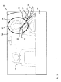
- Figur 2
- ist eine schematische Darstellung einer zweiten Ausführung der erfindungsgemäßen Vorrichtung in einem Fahrzeug,
- Figur 3
- ist eine schematische Darstellung einer dritten Ausführung der erfindungsgemäßen Vorrichtung in einem Fahrzeug,
- Figur 4
- ist eine schematische Darstellung eines Atemalkoholmessgerätes mit einem Signalgeber und
- Figur 5
- ist ein Blockschaltbild der erfindungsgemäßen Vorrichtung in einem Interlook-System.
- FIG. 1
- is a schematic representation of a first embodiment of the device according to the invention in a vehicle,
- FIG. 2
- is a schematic representation of a second embodiment of the device according to the invention in a vehicle,
- FIG. 3
- is a schematic representation of a third embodiment of the device according to the invention in a vehicle,
- FIG. 4
- is a schematic representation of a Atemalkoholmessgerätes with a signal generator and
- FIG. 5
- is a block diagram of the device according to the invention in an interlook system.
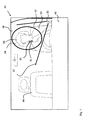
In
Das Alkoholmessgerät 10 weist ferner einen Signalgeber 20 auf, der während oder vor einer Alkoholmessung ein Signal ausgibt, wobei ein von dem Signalgeber 20 im inneren Bildfeldbereich 34 abgegebenes Signal von der Kameraeinheit 30 erfassbar ist. Eine Auswerte- und Steuereinheit 54 (dargestellt in
Ferner kann in einem vorherigen Schritt mit der erfindungsgemäßen Vorrichtung sichergestellt werden, dass sich keine weitere Person im Bereich des Fahrersitzes 42 befindet. Dazu wird von der Kameraeinheit 30 eine Anzahl von Personen im inneren Bildfeldbereich 34 ermittelt, wobei bei der Ermittlung von mehr als einer Person im inneren Bildfeldbereich 34 eine Signalgabe erfolgt. In vorteilhafter Weise wird von der Kameraeinheit 30 ein Bild des inneren Bildfeldbereiches erfasst und gespeichert.Furthermore, it can be ensured in a previous step with the device according to the invention that there is no further person in the area of the driver's
Sowohl das Alkoholmessgerät 10 als auch die Kameraeinheit 30 sind mit der Auswerte- und Steuereinheit 54 verbunden. Nach einer Betätigung der Starteinrichtung 48 des Fahrzeuges 40 signalisiert das Interlock-System der Testperson 50 den Beginn einer Alkoholmessung. Die Kameraeinheit 30 wird aktiviert und überwacht in dem inneren Bildfeldbereich 34 ein Vorhandensein des infraroten Signals innerhalb des inneren Bildfeldbereiches 34. Wird kein infrarotes Signal von der Kameraeinheit 30 innerhalb des inneren Bildfeldbereiches 34 erkannt, kann von dem Interlock-System eine neue Alkoholmessung gefordert werden.Both the
Alternativ ist es auch möglich, dass die Kameraeinheit 30 mit der Betätigung der Starteinrichtung 48 des Fahrzeuges 40 durch die Testperson 50 in Bereitschaft geht, aber erst nach einer Bestätigung an dem Alkoholmessgerät 10, beispielsweise durch Betätigung einer an dem Alkoholmessgerät 10 vorgesehenen Aktivierungstaste aktiviert wird.Alternatively, it is also possible that the
In einer weiteren Ausgestaltung der erfindungsgemäßen Vorrichtung ist die Kameraeinheit eingerichtet, zu Beginn der Alkoholmessung alle Veränderungen innerhalb des inneren Bildfeldbereiches 34 und zumindest teilweise des äußeren Bildfeldbereiches 36 zu registrieren. In einer besonderen Ausgestaltung des erfindungsgemäßen Verfahrens werden Veränderungen in einem Grenzbereich 38, beispielsweise durch eine Bewegung der Testperson 50, aus dem inneren Bildfeldbereich 34 in den äußeren Bildfeldbereich 36 oder einer weiteren Person von dem äußeren Bildfeldbereich 36 in den inneren Bildfeldbereich 34 von der Kameraeinheit 30 erfasst und von der Auswerte- und Steuereinheit 54 ausgewertet. Die Auswerte- und Steuereinheit 54 signalisiert eine nicht korrekte Anwendung des Alkoholmessgerätes 10. Das bedeutet, dass während einer Alkoholmessung die Testperson 50 auf den Fahrersitz 42 des Fahrzeuges 40 (im inneren Bildfeldbereich 34 der Kameraeinheit 30) verweilen muss. Während der Alkoholmessung sendet der an dem Alkoholmessgerät 10 vorgesehene Signalgeber 20 ein Infrarotes Signal, welches von der Kameraeinheit 30 registrierbar ist. Die Alkoholmessung wird von der Auswerte- und Steuereinheit 54 als gültig erkannt, wenn während der Dauer der Alkoholmessung keine Veränderung im Grenzbereich des inneren und äußeren Bildfeldbereiches 34 und 36 von der Kameraeinheit 30 detektiert worden ist und die Kameraeinheit 30 das infrarote Signal innerhalb des inneren Bildfeldbereiches 34 registriert hat. Wird kein infrarotes Signal von der Kameraeinheit 30 innerhalb des inneren Bildfeldbereiches 34 erkannt und / oder ist eine Veränderung im Grenzbereich des inneren und äußeren Bildfeldbereiches 34 und 36 von der Auswerte- und Steuereinheit 54 erkannt worden, kann von dem Interlock-System eine neue Alkoholmessung gefordert werden. Bei einer als gültig erklärten Alkoholmessung wird bei Vorliegen des Alkoholmesswertes im erlaubten Bereich die Starteinrichtung 48 des Fahrzeugs 40 frei geschalten und damit kann der Motor gestartet werden. Alternativ ist es auch in einer abgestuften Handlungsfolge möglich, bei einem Alkoholmesswert im erlaubten Bereich trotz nicht detektierten Signals des Signalgebers 20 des Alkoholmessgerätes 10 im inneren Bildfeldbereich 34 ein Starten des Fahrzeugs 40 zu ermöglichen. In diesen Fällen wird wenigstens das Bild des inneren Bildfeldbereiches 34 der Kameraeinheit 30 erfasst und von der Auswerte- und Steuereinheit 54 gespeichert.In a further embodiment of the device according to the invention, the camera unit is set up to register all changes within the inner
Bei dem erfindungsgemäßen Verfahren wird die nicht korrekte, regelwidrige Benutzung des Interlock-Systems dadurch dokumentiert, dass bei erkannter Regelwidrigkeit entweder bei einem nicht erkannten Alkoholmessgerät 10 im inneren Bildfeldbereich 34 oder einer Bewegung durch einen nicht erlaubten Grenzbereich 38 ebenfalls ein Triggersignal für die Dokumentation des Ereignisses mittels der Kameraeinheit 30 gesetzt wird.In the method according to the invention, the incorrect, irregular use of the interlock system is documented by the fact that when detected irregularity either with an
In einem alternativen Verfahren der weiteren Verfahrensfolge, d.h. in dem eine Freigabe der Starteinrichtung 48 ausschließlich an den Messwert der Alkoholmessung geknüpft wird, wird die potenziell regelwidrige Benutzung des Fahrzeuges 40 von der Testperson 50 als Ereignis dokumentiert, das einen Hinweis auf diese potenzielle Regelverletzung beinhaltet. Eine Dokumentation des Ereignisses kann beispielsweise durch eine Textbeschreibung in der Auswerte- und Steuereinheit 54 erfolgen.In an alternative method of the further process sequence, i. In that a release of the starting
In
Wie aus den
In der in
Alternativ zu den Ausführungen der
Die
In einer weiteren Ausführung kann das komplette Interlock-System mittels eines drahtlosen Kommunikationssystems mit einer zentralen Speichereinheit verbunden sein, auf welche die Daten in regelmäßigen Abständen übertragen werden. Kriterien für die Übertragung können sowohl zeitliche Abstände, beispielsweise Tage sein, oder das Speichervolumen der im Fahrzeug 40 integrierten Speichereinheit 56 oder eine Kombination aus beiden.In a further embodiment, the complete interlock system may be connected by means of a wireless communication system to a central storage unit to which the data is transmitted at regular intervals. Criteria for the transmission can be both time intervals, for example days, or the storage volume of the
Die Anwendung der erfindungsgemäßen Vorrichtung in Kombination mit einem Interlock-System in einem Fahrzeug 40 stellt nur eine Ausführungsvariante dar. Alternativ hierzu kann die erfindungsgemäße Vorrichtung in einer Zugangskontrolle für industrielle Sicherheitsbereiche, beispielsweise in der chemischen Industrie, oder aber auch beispielsweise für die Freigabe eines Bedienfeldes einer Maschine integriert sein.The application of the device according to the invention in combination with an interlock system in a
Während die vorliegende Erfindung unter Bezugnahme auf die bevorzugten Ausführungsbeispiele beschrieben worden ist, sind dem Fachmann verschiedene Änderungen und Modifikation klar. All diese Änderungen und Modifikationen sollen in den Schutzbereich der angefügten Ansprüche fallen.While the present invention has been described with reference to the preferred embodiments, various changes and modifications will be apparent to those skilled in the art. All such changes and modifications are intended to be within the scope of the appended claims.
- 1010
- Alkoholmessgerätalcohol Detector
- 1212
- Mundstückmouthpiece
- 1414
- Sensorsensor
- 1616
- MessauswerteeinrichtungMessauswerteeinrichtung
- 1818
- Kommunikationsanschluss für KabelmontageCommunication connector for cable mounting
- 1919
- Kommunikationsanschluss für funkgetragene Kommunikation zur Auswerte- und SteuereinheitCommunication connection for radio-supported communication to the evaluation and control unit
- 2020
- Signalgebersignaler
- 2222
- Licht reflektierendes ElementLight reflective element
- 2424
- Sendesignalsend signal
- 2626
- Reflektorsignalreflector signal
- 2828
- Lichtquellelight source
- 3030
- Kameraeinheitcamera unit
- 3232
- Bildfeld der KameraeinheitImage field of the camera unit
- 3434
- innerer Bildfeldbereichinner frame area
- 3636
- äußerer Bildfeldbereichouter image area
- 3838
- Grenzbereichborder area
- 4040
- Fahrzeugvehicle
- 4242
- Fahrersitzdriver's seat
- 4444
- Beifahrersitzpassenger seat
- 4646
- Armaturenbrettdashboard
- 4848
- Starteinrichtungstarting device
- 5050
- Testpersonsubject
- 5252
- Aufforderungseinheitrequesting unit
- 5454
- Auswerte- und SteuereinheitEvaluation and control unit
- 5656
- Speichereinheitstorage unit
- 5858
- Sende- und EmpfangseinheitTransmitting and receiving unit
Claims (15)
- Apparatus for recognizing a correct use of an alcohol measuring device (10) by a test person (50) comprising at least the alcohol measuring device (10), an evaluation and control unit (54) and a camera unit (30), wherein the image field (32) of the camera unit (30) is divided into an inner image field portion (34) and an outer image field portion (36), characterized in that
the alcohol measuring device (10) is realized with a signal generator (20), the inner image field portion (34) covers at least the face region of the test person (50), and the camera unit (30) is adapted to detect a signal provided by the signal generator (20) in the inner image field portion (34), and the evaluation and control unit (54) is adapted to evaluate this provided signal. - Apparatus according to claim 1, characterized in that the alcohol measuring device (10) measures the alcohol concentration of a breath sample provided by the test person (50).
- Apparatus according to any of the preceding claims, characterized in that the camera unit (30) comprises an infrared camera and the signal generator (20) provides an infrared signal, which preferably can be switched on and off alternatingly.
- Apparatus according to any of the preceding claims, characterized in that the camera unit (30) operates in the visible spectral range.
- Apparatus according to claim 4, characterized in that the signal generator (20) provides an optical signal, which preferably comprises alternatingly red and yellow light, or the signal generator (20) is constructed as a light reflecting element (22) and a light source (28) is provided for illuminating the signal generator (20).
- Apparatus according to any of the preceding claims, characterized in that the inner image field portion (34) and, preferably, the outer image field portion (36) of the camera unit (30) have an oval shape.
- Apparatus according to any of the preceding claims, characterized in that the camera unit (30) is adapted to detect movements from the inner image field portion (34) to the outer image field portion (36) and/or from the outer image field portion (36) to the inner image field portion (34), and the evaluation and control unit (54) is adapted to evaluate these movements.
- Apparatus according to any of the preceding claims, characterized in that the boundary between the inner image field portion (34) and the outer image field portion (36) is constructed as a boundary region (38).
- Apparatus according to any of the preceding claims, characterized in that a storage unit (56) for recording images of the inner image field portion (34) is provided, which storage unit (56) is preferably constructed as a part of the camera unit (30).
- Apparatus for recognizing a correct use of an alcohol measuring device (10) by a test person (50) according to any of the preceding claims in combination with a system for checking the alcohol concentration of the test person (50), comprising at least:a vehicle (40) and an immobilizer,wherein the immobilizer is connected at least with the alcohol measuring device (10) andthe camera unit (30) is installed in the vehicle (40) in such a manner that the inner image field portion (34) completely covers the region of a driver seat (42).
- Method for recognizing a correct use of an alcohol measuring device (10) by a test person (50) comprising the following steps:a) a camera unit (30), the image field (32) of which is divided into an inner image field portion (34) and an outer image field portion (36), registers the inner image field portion (34) and the outer image field portion (36) at the beginning of the alcohol measurement,b) a signal generator (20) provided on the alcohol measuring device (10) transmits a signal during the alcohol measurement, which signal can be registered by the camera unit (30),c) an evaluation and control unit (54) evaluates the signal, andd) the alcohol measurement is recognized as valid by an evaluation unit and control unit (54), if during the alcohol measurement the signal was detected within the inner image field portion (34).
- Method according to claim 11, characterized in that the camera unit (30) is activated prior to the alcohol measurement, preferably following an initiation of the start process of the vehicle (40).
- Method according to claim 11 or 12, characterized in that in step a) a number of persons within the inner image field portion (34) is determined by the camera unit (30), wherein preferably upon a determination of more than one person within the inner image field portion (34) a signal generation is carried out and/or the alcohol measurement is not started.
- Method according to claim 11, characterized in that in method step b) the signal generator (20) transmit an infrared signal, which is preferably switched on and off alternatingly, or transmits at least one light signal, which preferably comprises alternatingly red and yellow light, and/or the light intensity of a light signal is varied.
- Method according to claim 11, characterized in that the camera unit (30) detects changes at the boundary between the inner image field portion (34) and the outer image field portion (36) starting with the beginning of the alcohol measurement, and the evaluation and control unit (54) evaluates these changes.
Priority Applications (2)
| Application Number | Priority Date | Filing Date | Title |
|---|---|---|---|
| EP09157268.5A EP2237034B1 (en) | 2009-04-03 | 2009-04-03 | Device and method for recognising the correct usage of an alcohol measuring device |
| US12/546,144 US8795187B2 (en) | 2008-09-02 | 2009-08-24 | Device and process for recognizing a correct use of an alcohol measuring device |
Applications Claiming Priority (1)
| Application Number | Priority Date | Filing Date | Title |
|---|---|---|---|
| EP09157268.5A EP2237034B1 (en) | 2009-04-03 | 2009-04-03 | Device and method for recognising the correct usage of an alcohol measuring device |
Publications (2)
| Publication Number | Publication Date |
|---|---|
| EP2237034A1 EP2237034A1 (en) | 2010-10-06 |
| EP2237034B1 true EP2237034B1 (en) | 2013-07-24 |
Family
ID=42670662
Family Applications (1)
| Application Number | Title | Priority Date | Filing Date |
|---|---|---|---|
| EP09157268.5A Active EP2237034B1 (en) | 2008-09-02 | 2009-04-03 | Device and method for recognising the correct usage of an alcohol measuring device |
Country Status (2)
| Country | Link |
|---|---|
| US (1) | US8795187B2 (en) |
| EP (1) | EP2237034B1 (en) |
Families Citing this family (32)
| Publication number | Priority date | Publication date | Assignee | Title |
|---|---|---|---|---|
| US9228997B2 (en) | 2009-10-02 | 2016-01-05 | Soberlink, Inc. | Sobriety monitoring system |
| US8707758B2 (en) | 2009-10-02 | 2014-04-29 | Soberlink, Inc. | Sobriety monitoring system |
| US9417232B2 (en) | 2009-10-02 | 2016-08-16 | Bi Mobile Breath, Inc. | Sobriety monitoring system |
| US8381573B2 (en) * | 2009-10-02 | 2013-02-26 | Brad Keays | Sobriety monitoring system |
| US8718536B2 (en) | 2011-01-18 | 2014-05-06 | Marwan Hannon | Apparatus, system, and method for detecting the presence and controlling the operation of mobile devices within a vehicle |
| US8686864B2 (en) | 2011-01-18 | 2014-04-01 | Marwan Hannon | Apparatus, system, and method for detecting the presence of an intoxicated driver and controlling the operation of a vehicle |
| US8548206B2 (en) | 2011-01-20 | 2013-10-01 | Daon Holdings Limited | Methods and systems for capturing biometric data |
| US8479864B2 (en) * | 2011-03-09 | 2013-07-09 | Tk Holdings Inc. | System and method for disabling a vehicle |
| US20120236136A1 (en) * | 2011-03-15 | 2012-09-20 | Magna Mirrors Of America, Inc. | Interior rearview mirror with alcohol detection |
| US10328800B2 (en) * | 2012-06-18 | 2019-06-25 | Alcohol Countermeasure Systems (International) Inc. | Vehicle interlock with location detection |
| CA2835984C (en) | 2012-12-07 | 2020-11-03 | Felix J. E. Comeau | Data extraction method |
| DE102013015826B4 (en) | 2013-09-24 | 2016-05-12 | Dräger Safety AG & Co. KGaA | Device for measuring the state of intoxication of a subject |
| US9829480B2 (en) | 2013-09-26 | 2017-11-28 | Alcohol Monitoring Systems, Inc. | Remote breath alcohol monitor |
| US9201145B2 (en) * | 2013-10-17 | 2015-12-01 | Globalfoundries Inc. | Object location in three dimensional space using LED lights |
| US10277837B2 (en) * | 2013-11-05 | 2019-04-30 | Visteon Global Technologies, Inc. | System and method for monitoring a driver of a vehicle |
| US9278696B2 (en) * | 2014-06-14 | 2016-03-08 | Ge Yi | Vehicle onboard safety system |
| CN104122858B (en) * | 2014-06-30 | 2016-11-02 | 济南大学 | A kind of restriction operates the control system of electrical equipment after drinking |
| WO2016044926A1 (en) * | 2014-09-23 | 2016-03-31 | Rarama Exequiel | Improved breath alcohol ignition interlock system |
| BR112017019402A2 (en) | 2015-03-11 | 2018-05-02 | 3M Innovative Properties Company | mobile offender and alcohol monitoring system for wrist use |
| JP2018522239A (en) | 2015-07-14 | 2018-08-09 | ドライビング マネージメント システムズ, インコーポレイテッド | Phone location detection using RF radio and ultrasound signals |
| US9922508B2 (en) | 2015-10-09 | 2018-03-20 | Soberlink Healthcare, Llc | Bioresistive-fingerprint based sobriety monitoring system |
| FR3042279A1 (en) | 2015-10-12 | 2017-04-14 | Aperli | METHOD FOR CERTIFYING THE SELF-DETECTION OF A GAS SUBSTANCE IN THE AIR EXCHANGES USING A DEPTH TERMINAL |
| US10604011B2 (en) | 2015-10-13 | 2020-03-31 | Consumer Safety Technology, Llc | Networked intoxication vehicle immobilization |
| US10488398B2 (en) | 2015-12-17 | 2019-11-26 | #1 A Lifesafer, Inc. | Chemical impairment detection system with an integrated, multi-function breath chamber |
| US10557844B2 (en) | 2016-04-08 | 2020-02-11 | Soberlink Healthcare, Llc | Bioresistive-fingerprint based sobriety monitoring system |
| CN106042923A (en) * | 2016-07-21 | 2016-10-26 | 成都安程通科技有限公司 | Vehicle-mounted drunk driving detection system |
| DE102016009834A1 (en) * | 2016-08-15 | 2018-02-15 | Dräger Safety AG & Co. KGaA | Device, substance measuring device, method, computer program camera and mobile device for identifying a substance measuring device |
| US10663440B2 (en) | 2016-09-09 | 2020-05-26 | Consumer Safety Technology, Llc | Secure data handling in a breath alcohol calibration station |
| US10877008B2 (en) | 2016-09-09 | 2020-12-29 | Consumer Safety Technology, Llc | Reference gas management in a breath alcohol calibration station |
| LT6640B (en) * | 2017-12-04 | 2019-08-12 | Uab Universumas | Equipment for measuring the human alcohol intoxication level to prevent falsification of measurement and results and method for measuring |
| CN110470825B (en) * | 2019-09-18 | 2021-03-19 | 江苏科技大学 | Wearable alcohol content detection device for assisting driving |
| DE102021212388A1 (en) | 2021-11-03 | 2023-05-04 | Robert Bosch Gesellschaft mit beschränkter Haftung | Method and apparatus for detecting tampering with a breathalyser test for a vehicle and monitoring system for a vehicle |
Family Cites Families (18)
| Publication number | Priority date | Publication date | Assignee | Title |
|---|---|---|---|---|
| IN160562B (en) * | 1983-04-26 | 1987-07-18 | Gkn Technology Ltd | |
| US4916435A (en) * | 1988-05-10 | 1990-04-10 | Guardian Technologies, Inc. | Remote confinement monitoring station and system incorporating same |
| US7570785B2 (en) * | 1995-06-07 | 2009-08-04 | Automotive Technologies International, Inc. | Face monitoring system and method for vehicular occupants |
| US6075445A (en) * | 1998-06-19 | 2000-06-13 | Mcloughlin; John E. | High-temperature warning unit |
| US6433863B1 (en) * | 2001-01-08 | 2002-08-13 | Ronald Weiss | Combination breathalyzer and eye-sensor |
| KR100503039B1 (en) * | 2002-11-25 | 2005-07-22 | 삼성테크윈 주식회사 | Method to control operation of digital camera for user to easily take an identification photograph |
| US6748792B1 (en) * | 2003-03-07 | 2004-06-15 | Lifesafer Interlock, Inc. | Impairment detection and interlock system with tester identification |
| US7440593B1 (en) * | 2003-06-26 | 2008-10-21 | Fotonation Vision Limited | Method of improving orientation and color balance of digital images using face detection information |
| JP4153444B2 (en) * | 2004-02-18 | 2008-09-24 | 富士フイルム株式会社 | Digital camera |
| EP1591296A1 (en) * | 2004-04-30 | 2005-11-02 | LifeSafer Interlock, Inc. | Alcohol impairment detection and interlock system with tester identification |
| US7315631B1 (en) * | 2006-08-11 | 2008-01-01 | Fotonation Vision Limited | Real-time face tracking in a digital image acquisition device |
| JP2006338377A (en) * | 2005-06-02 | 2006-12-14 | Fujifilm Holdings Corp | Image correction method, apparatus, and program |
| KR100725895B1 (en) * | 2005-09-15 | 2007-06-08 | 주식회사 아이캔텍 | Apparatus for optical data input using optical fiber |
| JP4347345B2 (en) | 2007-01-15 | 2009-10-21 | 日本電気株式会社 | Alcohol testing apparatus and alcohol testing method |
| JP4604073B2 (en) * | 2007-10-03 | 2010-12-22 | 本田技研工業株式会社 | Vehicle drunk driving prevention device |
| WO2009048809A1 (en) * | 2007-10-10 | 2009-04-16 | B.E.S.T. Labs, Inc. | Breath alcohol ignition interlock device with biometric facial recognition with real-time verification of the user |
| JP2009160988A (en) * | 2007-12-28 | 2009-07-23 | Omron Corp | Detection device and method, and program |
| WO2010009406A2 (en) * | 2008-07-17 | 2010-01-21 | Consumer Safety Technology, Inc. | Ignition interlock breathalyzer |
-
2009
- 2009-04-03 EP EP09157268.5A patent/EP2237034B1/en active Active
- 2009-08-24 US US12/546,144 patent/US8795187B2/en active Active
Also Published As
| Publication number | Publication date |
|---|---|
| US20100251804A1 (en) | 2010-10-07 |
| US8795187B2 (en) | 2014-08-05 |
| EP2237034A1 (en) | 2010-10-06 |
Similar Documents
| Publication | Publication Date | Title |
|---|---|---|
| EP2237034B1 (en) | Device and method for recognising the correct usage of an alcohol measuring device | |
| EP2263904B1 (en) | Alcohol interlock system with wireless data transfer and security function | |
| DE102004005163B3 (en) | Alertness detection device for vehicle driver using intermittent illumination of eye and evaluation of pupil reaction | |
| DE102013018663B4 (en) | Device and a method for measuring an alcohol or Rauschmittelanteils in the breath of a driver | |
| DE112017005357B4 (en) | Vehicle door device | |
| DE60300919T2 (en) | Image pickup device of the vehicle occupants in a vehicle | |
| DE102015115005A1 (en) | Vehicle control system for occupant protection and method thereof | |
| EP2390129A1 (en) | Device and method for recognising the correct usage of an alcohol measuring device by a driver in a vehicle | |
| DE102013015826A1 (en) | Device for measuring the state of intoxication of a subject | |
| DE102020120588A1 (en) | STATUS OF A SEAT BELT FOR AN OCCUPANT | |
| DE102011015457A1 (en) | Method and device for detecting a vehicle movement | |
| DE102016202376A1 (en) | Starting mechanism for a motor vehicle | |
| DE102014220713A1 (en) | Method and device for adjusting an exterior mirror | |
| DE102012011154A1 (en) | Method and monitoring device for monitoring operation of a vehicle | |
| EP0921041B1 (en) | Arrangement for controlling electronic devices in a vehicle | |
| DE102016211034A1 (en) | Information providing device for a vehicle | |
| DE102015016514B4 (en) | Method for automatically locking a door of a motor vehicle | |
| DE102017214605A1 (en) | Passenger detection with emergency treatment in a motor vehicle | |
| DE102010052547B4 (en) | Motor vehicle with a device for automatically switching off a drive | |
| EP2977253A1 (en) | Starting mechanism for a motor vehicle | |
| DE102012202649A1 (en) | Device for determining driving capability of driver of motor car, installed in steering wheel, has output unit that provides drive information or information derived from driver to driver assistance system | |
| DE10143263C1 (en) | Procedure for unlocking a trunk hood | |
| EP2100763B1 (en) | Method and device for monitoring a motorised device and mobile device | |
| DE102016011246A1 (en) | A method of monitoring a condition of at least one occupant of a vehicle | |
| DE102019210058B3 (en) | Device and method for object recognition in the underbody area of a motor vehicle |
Legal Events
| Date | Code | Title | Description |
|---|---|---|---|
| PUAI | Public reference made under article 153(3) epc to a published international application that has entered the european phase |
Free format text: ORIGINAL CODE: 0009012 |
|
| 17P | Request for examination filed |
Effective date: 20091009 |
|
| AK | Designated contracting states |
Kind code of ref document: A1 Designated state(s): AT BE BG CH CY CZ DE DK EE ES FI FR GB GR HR HU IE IS IT LI LT LU LV MC MK MT NL NO PL PT RO SE SI SK TR |
|
| 17Q | First examination report despatched |
Effective date: 20111108 |
|
| GRAP | Despatch of communication of intention to grant a patent |
Free format text: ORIGINAL CODE: EPIDOSNIGR1 |
|
| GRAS | Grant fee paid |
Free format text: ORIGINAL CODE: EPIDOSNIGR3 |
|
| GRAA | (expected) grant |
Free format text: ORIGINAL CODE: 0009210 |
|
| AK | Designated contracting states |
Kind code of ref document: B1 Designated state(s): AT BE BG CH CY CZ DE DK EE ES FI FR GB GR HR HU IE IS IT LI LT LU LV MC MK MT NL NO PL PT RO SE SI SK TR |
|
| REG | Reference to a national code |
Ref country code: GB Ref legal event code: FG4D Free format text: NOT ENGLISH |
|
| REG | Reference to a national code |
Ref country code: CH Ref legal event code: EP |
|
| REG | Reference to a national code |
Ref country code: AT Ref legal event code: REF Ref document number: 623712 Country of ref document: AT Kind code of ref document: T Effective date: 20130815 |
|
| REG | Reference to a national code |
Ref country code: IE Ref legal event code: FG4D Free format text: LANGUAGE OF EP DOCUMENT: GERMAN |
|
| REG | Reference to a national code |
Ref country code: DE Ref legal event code: R096 Ref document number: 502009007632 Country of ref document: DE Effective date: 20130919 |
|
| REG | Reference to a national code |
Ref country code: SE Ref legal event code: TRGR |
|
| REG | Reference to a national code |
Ref country code: NL Ref legal event code: T3 |
|
| REG | Reference to a national code |
Ref country code: LT Ref legal event code: MG4D |
|
| PG25 | Lapsed in a contracting state [announced via postgrant information from national office to epo] |
Ref country code: CY Free format text: LAPSE BECAUSE OF FAILURE TO SUBMIT A TRANSLATION OF THE DESCRIPTION OR TO PAY THE FEE WITHIN THE PRESCRIBED TIME-LIMIT Effective date: 20130911 Ref country code: HR Free format text: LAPSE BECAUSE OF FAILURE TO SUBMIT A TRANSLATION OF THE DESCRIPTION OR TO PAY THE FEE WITHIN THE PRESCRIBED TIME-LIMIT Effective date: 20130724 Ref country code: NO Free format text: LAPSE BECAUSE OF FAILURE TO SUBMIT A TRANSLATION OF THE DESCRIPTION OR TO PAY THE FEE WITHIN THE PRESCRIBED TIME-LIMIT Effective date: 20131024 Ref country code: LT Free format text: LAPSE BECAUSE OF FAILURE TO SUBMIT A TRANSLATION OF THE DESCRIPTION OR TO PAY THE FEE WITHIN THE PRESCRIBED TIME-LIMIT Effective date: 20130724 Ref country code: IS Free format text: LAPSE BECAUSE OF FAILURE TO SUBMIT A TRANSLATION OF THE DESCRIPTION OR TO PAY THE FEE WITHIN THE PRESCRIBED TIME-LIMIT Effective date: 20131124 Ref country code: PT Free format text: LAPSE BECAUSE OF FAILURE TO SUBMIT A TRANSLATION OF THE DESCRIPTION OR TO PAY THE FEE WITHIN THE PRESCRIBED TIME-LIMIT Effective date: 20131125 |
|
| PG25 | Lapsed in a contracting state [announced via postgrant information from national office to epo] |
Ref country code: PL Free format text: LAPSE BECAUSE OF FAILURE TO SUBMIT A TRANSLATION OF THE DESCRIPTION OR TO PAY THE FEE WITHIN THE PRESCRIBED TIME-LIMIT Effective date: 20130724 Ref country code: ES Free format text: LAPSE BECAUSE OF FAILURE TO SUBMIT A TRANSLATION OF THE DESCRIPTION OR TO PAY THE FEE WITHIN THE PRESCRIBED TIME-LIMIT Effective date: 20130724 Ref country code: GR Free format text: LAPSE BECAUSE OF FAILURE TO SUBMIT A TRANSLATION OF THE DESCRIPTION OR TO PAY THE FEE WITHIN THE PRESCRIBED TIME-LIMIT Effective date: 20131025 Ref country code: LV Free format text: LAPSE BECAUSE OF FAILURE TO SUBMIT A TRANSLATION OF THE DESCRIPTION OR TO PAY THE FEE WITHIN THE PRESCRIBED TIME-LIMIT Effective date: 20130724 Ref country code: SI Free format text: LAPSE BECAUSE OF FAILURE TO SUBMIT A TRANSLATION OF THE DESCRIPTION OR TO PAY THE FEE WITHIN THE PRESCRIBED TIME-LIMIT Effective date: 20130724 Ref country code: FI Free format text: LAPSE BECAUSE OF FAILURE TO SUBMIT A TRANSLATION OF THE DESCRIPTION OR TO PAY THE FEE WITHIN THE PRESCRIBED TIME-LIMIT Effective date: 20130724 |
|
| PG25 | Lapsed in a contracting state [announced via postgrant information from national office to epo] |
Ref country code: CY Free format text: LAPSE BECAUSE OF FAILURE TO SUBMIT A TRANSLATION OF THE DESCRIPTION OR TO PAY THE FEE WITHIN THE PRESCRIBED TIME-LIMIT Effective date: 20130724 |
|
| PG25 | Lapsed in a contracting state [announced via postgrant information from national office to epo] |
Ref country code: SK Free format text: LAPSE BECAUSE OF FAILURE TO SUBMIT A TRANSLATION OF THE DESCRIPTION OR TO PAY THE FEE WITHIN THE PRESCRIBED TIME-LIMIT Effective date: 20130724 Ref country code: DK Free format text: LAPSE BECAUSE OF FAILURE TO SUBMIT A TRANSLATION OF THE DESCRIPTION OR TO PAY THE FEE WITHIN THE PRESCRIBED TIME-LIMIT Effective date: 20130724 Ref country code: RO Free format text: LAPSE BECAUSE OF FAILURE TO SUBMIT A TRANSLATION OF THE DESCRIPTION OR TO PAY THE FEE WITHIN THE PRESCRIBED TIME-LIMIT Effective date: 20130724 Ref country code: EE Free format text: LAPSE BECAUSE OF FAILURE TO SUBMIT A TRANSLATION OF THE DESCRIPTION OR TO PAY THE FEE WITHIN THE PRESCRIBED TIME-LIMIT Effective date: 20130724 Ref country code: CZ Free format text: LAPSE BECAUSE OF FAILURE TO SUBMIT A TRANSLATION OF THE DESCRIPTION OR TO PAY THE FEE WITHIN THE PRESCRIBED TIME-LIMIT Effective date: 20130724 |
|
| PG25 | Lapsed in a contracting state [announced via postgrant information from national office to epo] |
Ref country code: IT Free format text: LAPSE BECAUSE OF FAILURE TO SUBMIT A TRANSLATION OF THE DESCRIPTION OR TO PAY THE FEE WITHIN THE PRESCRIBED TIME-LIMIT Effective date: 20130724 |
|
| PLBE | No opposition filed within time limit |
Free format text: ORIGINAL CODE: 0009261 |
|
| STAA | Information on the status of an ep patent application or granted ep patent |
Free format text: STATUS: NO OPPOSITION FILED WITHIN TIME LIMIT |
|
| 26N | No opposition filed |
Effective date: 20140425 |
|
| REG | Reference to a national code |
Ref country code: DE Ref legal event code: R097 Ref document number: 502009007632 Country of ref document: DE Effective date: 20140425 |
|
| PG25 | Lapsed in a contracting state [announced via postgrant information from national office to epo] |
Ref country code: LU Free format text: LAPSE BECAUSE OF FAILURE TO SUBMIT A TRANSLATION OF THE DESCRIPTION OR TO PAY THE FEE WITHIN THE PRESCRIBED TIME-LIMIT Effective date: 20140403 Ref country code: MC Free format text: LAPSE BECAUSE OF FAILURE TO SUBMIT A TRANSLATION OF THE DESCRIPTION OR TO PAY THE FEE WITHIN THE PRESCRIBED TIME-LIMIT Effective date: 20130724 |
|
| REG | Reference to a national code |
Ref country code: CH Ref legal event code: PL |
|
| GBPC | Gb: european patent ceased through non-payment of renewal fee |
Effective date: 20140403 |
|
| REG | Reference to a national code |
Ref country code: IE Ref legal event code: MM4A |
|
| PG25 | Lapsed in a contracting state [announced via postgrant information from national office to epo] |
Ref country code: CH Free format text: LAPSE BECAUSE OF NON-PAYMENT OF DUE FEES Effective date: 20140430 Ref country code: GB Free format text: LAPSE BECAUSE OF NON-PAYMENT OF DUE FEES Effective date: 20140403 Ref country code: LI Free format text: LAPSE BECAUSE OF NON-PAYMENT OF DUE FEES Effective date: 20140430 |
|
| PG25 | Lapsed in a contracting state [announced via postgrant information from national office to epo] |
Ref country code: IE Free format text: LAPSE BECAUSE OF NON-PAYMENT OF DUE FEES Effective date: 20140403 |
|
| REG | Reference to a national code |
Ref country code: AT Ref legal event code: MM01 Ref document number: 623712 Country of ref document: AT Kind code of ref document: T Effective date: 20140403 |
|
| PG25 | Lapsed in a contracting state [announced via postgrant information from national office to epo] |
Ref country code: AT Free format text: LAPSE BECAUSE OF NON-PAYMENT OF DUE FEES Effective date: 20140403 |
|
| PG25 | Lapsed in a contracting state [announced via postgrant information from national office to epo] |
Ref country code: MT Free format text: LAPSE BECAUSE OF FAILURE TO SUBMIT A TRANSLATION OF THE DESCRIPTION OR TO PAY THE FEE WITHIN THE PRESCRIBED TIME-LIMIT Effective date: 20130724 |
|
| REG | Reference to a national code |
Ref country code: FR Ref legal event code: PLFP Year of fee payment: 8 |
|
| PG25 | Lapsed in a contracting state [announced via postgrant information from national office to epo] |
Ref country code: BG Free format text: LAPSE BECAUSE OF FAILURE TO SUBMIT A TRANSLATION OF THE DESCRIPTION OR TO PAY THE FEE WITHIN THE PRESCRIBED TIME-LIMIT Effective date: 20130724 |
|
| PG25 | Lapsed in a contracting state [announced via postgrant information from national office to epo] |
Ref country code: BE Free format text: LAPSE BECAUSE OF FAILURE TO SUBMIT A TRANSLATION OF THE DESCRIPTION OR TO PAY THE FEE WITHIN THE PRESCRIBED TIME-LIMIT Effective date: 20140430 Ref country code: TR Free format text: LAPSE BECAUSE OF FAILURE TO SUBMIT A TRANSLATION OF THE DESCRIPTION OR TO PAY THE FEE WITHIN THE PRESCRIBED TIME-LIMIT Effective date: 20130724 Ref country code: HU Free format text: LAPSE BECAUSE OF FAILURE TO SUBMIT A TRANSLATION OF THE DESCRIPTION OR TO PAY THE FEE WITHIN THE PRESCRIBED TIME-LIMIT; INVALID AB INITIO Effective date: 20090403 |
|
| REG | Reference to a national code |
Ref country code: FR Ref legal event code: PLFP Year of fee payment: 9 |
|
| REG | Reference to a national code |
Ref country code: FR Ref legal event code: PLFP Year of fee payment: 10 |
|
| PG25 | Lapsed in a contracting state [announced via postgrant information from national office to epo] |
Ref country code: MK Free format text: LAPSE BECAUSE OF FAILURE TO SUBMIT A TRANSLATION OF THE DESCRIPTION OR TO PAY THE FEE WITHIN THE PRESCRIBED TIME-LIMIT Effective date: 20130724 |
|
| PGFP | Annual fee paid to national office [announced via postgrant information from national office to epo] |
Ref country code: NL Payment date: 20230417 Year of fee payment: 15 |
|
| PGFP | Annual fee paid to national office [announced via postgrant information from national office to epo] |
Ref country code: FR Payment date: 20230417 Year of fee payment: 15 Ref country code: DE Payment date: 20230418 Year of fee payment: 15 |
|
| PGFP | Annual fee paid to national office [announced via postgrant information from national office to epo] |
Ref country code: SE Payment date: 20230419 Year of fee payment: 15 |