EP3268548B1 - Trägersystem und verfahren zur errichtung eines stützbogens - Google Patents
Trägersystem und verfahren zur errichtung eines stützbogens Download PDFInfo
- Publication number
- EP3268548B1 EP3268548B1 EP16760938.7A EP16760938A EP3268548B1 EP 3268548 B1 EP3268548 B1 EP 3268548B1 EP 16760938 A EP16760938 A EP 16760938A EP 3268548 B1 EP3268548 B1 EP 3268548B1
- Authority
- EP
- European Patent Office
- Prior art keywords
- clevis
- structural elements
- beam system
- hole
- pin
- Prior art date
- Legal status (The legal status is an assumption and is not a legal conclusion. Google has not performed a legal analysis and makes no representation as to the accuracy of the status listed.)
- Active
Links
Images


Classifications
-
- E—FIXED CONSTRUCTIONS
- E04—BUILDING
- E04B—GENERAL BUILDING CONSTRUCTIONS; WALLS, e.g. PARTITIONS; ROOFS; FLOORS; CEILINGS; INSULATION OR OTHER PROTECTION OF BUILDINGS
- E04B1/00—Constructions in general; Structures which are not restricted either to walls, e.g. partitions, or floors or ceilings or roofs
- E04B1/32—Arched structures; Vaulted structures; Folded structures
-
- E—FIXED CONSTRUCTIONS
- E04—BUILDING
- E04B—GENERAL BUILDING CONSTRUCTIONS; WALLS, e.g. PARTITIONS; ROOFS; FLOORS; CEILINGS; INSULATION OR OTHER PROTECTION OF BUILDINGS
- E04B1/00—Constructions in general; Structures which are not restricted either to walls, e.g. partitions, or floors or ceilings or roofs
- E04B1/18—Structures comprising elongated load-supporting parts, e.g. columns, girders, skeletons
- E04B1/24—Structures comprising elongated load-supporting parts, e.g. columns, girders, skeletons the supporting parts consisting of metal
- E04B1/2403—Connection details of the elongated load-supporting parts
-
- E—FIXED CONSTRUCTIONS
- E04—BUILDING
- E04B—GENERAL BUILDING CONSTRUCTIONS; WALLS, e.g. PARTITIONS; ROOFS; FLOORS; CEILINGS; INSULATION OR OTHER PROTECTION OF BUILDINGS
- E04B1/00—Constructions in general; Structures which are not restricted either to walls, e.g. partitions, or floors or ceilings or roofs
- E04B1/32—Arched structures; Vaulted structures; Folded structures
- E04B1/3205—Structures with a longitudinal horizontal axis, e.g. cylindrical or prismatic structures
-
- E—FIXED CONSTRUCTIONS
- E04—BUILDING
- E04B—GENERAL BUILDING CONSTRUCTIONS; WALLS, e.g. PARTITIONS; ROOFS; FLOORS; CEILINGS; INSULATION OR OTHER PROTECTION OF BUILDINGS
- E04B1/00—Constructions in general; Structures which are not restricted either to walls, e.g. partitions, or floors or ceilings or roofs
- E04B1/342—Structures covering a large free area, whether open-sided or not, e.g. hangars, halls
-
- E—FIXED CONSTRUCTIONS
- E04—BUILDING
- E04B—GENERAL BUILDING CONSTRUCTIONS; WALLS, e.g. PARTITIONS; ROOFS; FLOORS; CEILINGS; INSULATION OR OTHER PROTECTION OF BUILDINGS
- E04B1/00—Constructions in general; Structures which are not restricted either to walls, e.g. partitions, or floors or ceilings or roofs
- E04B1/343—Structures characterised by movable, separable, or collapsible parts, e.g. for transport
- E04B1/344—Structures characterised by movable, separable, or collapsible parts, e.g. for transport with hinged parts
- E04B1/3441—Structures characterised by movable, separable, or collapsible parts, e.g. for transport with hinged parts with articulated bar-shaped elements
-
- E—FIXED CONSTRUCTIONS
- E04—BUILDING
- E04B—GENERAL BUILDING CONSTRUCTIONS; WALLS, e.g. PARTITIONS; ROOFS; FLOORS; CEILINGS; INSULATION OR OTHER PROTECTION OF BUILDINGS
- E04B1/00—Constructions in general; Structures which are not restricted either to walls, e.g. partitions, or floors or ceilings or roofs
- E04B1/35—Extraordinary methods of construction, e.g. lift-slab, jack-block
- E04B1/3533—Extraordinary methods of construction, e.g. lift-slab, jack-block characterised by the raising of hingedly-connected building elements, e.g. arches, portal frames
-
- E—FIXED CONSTRUCTIONS
- E04—BUILDING
- E04C—STRUCTURAL ELEMENTS; BUILDING MATERIALS
- E04C3/00—Structural elongated elements designed for load-supporting
- E04C3/38—Arched girders or portal frames
- E04C3/40—Arched girders or portal frames of metal
-
- E—FIXED CONSTRUCTIONS
- E04—BUILDING
- E04H—BUILDINGS OR LIKE STRUCTURES FOR PARTICULAR PURPOSES; SWIMMING OR SPLASH BATHS OR POOLS; MASTS; FENCING; TENTS OR CANOPIES, IN GENERAL
- E04H3/00—Buildings or groups of buildings for public or similar purposes; Institutions, e.g. infirmaries or prisons
- E04H3/10—Buildings or groups of buildings for public or similar purposes; Institutions, e.g. infirmaries or prisons for meetings, entertainments, or sports
- E04H3/14—Gymnasiums; Other sporting buildings
-
- E—FIXED CONSTRUCTIONS
- E04—BUILDING
- E04H—BUILDINGS OR LIKE STRUCTURES FOR PARTICULAR PURPOSES; SWIMMING OR SPLASH BATHS OR POOLS; MASTS; FENCING; TENTS OR CANOPIES, IN GENERAL
- E04H6/00—Buildings for parking cars, rolling-stock, aircraft, vessels or like vehicles, e.g. garages
- E04H6/44—Buildings for parking cars, rolling-stock, aircraft, vessels or like vehicles, e.g. garages for storing aircraft
-
- E—FIXED CONSTRUCTIONS
- E04—BUILDING
- E04B—GENERAL BUILDING CONSTRUCTIONS; WALLS, e.g. PARTITIONS; ROOFS; FLOORS; CEILINGS; INSULATION OR OTHER PROTECTION OF BUILDINGS
- E04B1/00—Constructions in general; Structures which are not restricted either to walls, e.g. partitions, or floors or ceilings or roofs
- E04B1/18—Structures comprising elongated load-supporting parts, e.g. columns, girders, skeletons
- E04B1/24—Structures comprising elongated load-supporting parts, e.g. columns, girders, skeletons the supporting parts consisting of metal
- E04B1/2403—Connection details of the elongated load-supporting parts
- E04B2001/2433—Connection details of the elongated load-supporting parts using a removable key
-
- E—FIXED CONSTRUCTIONS
- E04—BUILDING
- E04B—GENERAL BUILDING CONSTRUCTIONS; WALLS, e.g. PARTITIONS; ROOFS; FLOORS; CEILINGS; INSULATION OR OTHER PROTECTION OF BUILDINGS
- E04B1/00—Constructions in general; Structures which are not restricted either to walls, e.g. partitions, or floors or ceilings or roofs
- E04B1/18—Structures comprising elongated load-supporting parts, e.g. columns, girders, skeletons
- E04B1/24—Structures comprising elongated load-supporting parts, e.g. columns, girders, skeletons the supporting parts consisting of metal
- E04B1/2403—Connection details of the elongated load-supporting parts
- E04B2001/2457—Beam to beam connections
-
- E—FIXED CONSTRUCTIONS
- E04—BUILDING
- E04B—GENERAL BUILDING CONSTRUCTIONS; WALLS, e.g. PARTITIONS; ROOFS; FLOORS; CEILINGS; INSULATION OR OTHER PROTECTION OF BUILDINGS
- E04B1/00—Constructions in general; Structures which are not restricted either to walls, e.g. partitions, or floors or ceilings or roofs
- E04B1/18—Structures comprising elongated load-supporting parts, e.g. columns, girders, skeletons
- E04B1/24—Structures comprising elongated load-supporting parts, e.g. columns, girders, skeletons the supporting parts consisting of metal
- E04B1/2403—Connection details of the elongated load-supporting parts
- E04B2001/2463—Connections to foundations
-
- E—FIXED CONSTRUCTIONS
- E04—BUILDING
- E04B—GENERAL BUILDING CONSTRUCTIONS; WALLS, e.g. PARTITIONS; ROOFS; FLOORS; CEILINGS; INSULATION OR OTHER PROTECTION OF BUILDINGS
- E04B1/00—Constructions in general; Structures which are not restricted either to walls, e.g. partitions, or floors or ceilings or roofs
- E04B1/18—Structures comprising elongated load-supporting parts, e.g. columns, girders, skeletons
- E04B1/24—Structures comprising elongated load-supporting parts, e.g. columns, girders, skeletons the supporting parts consisting of metal
- E04B2001/2493—Structures with a vaulted roof
-
- E—FIXED CONSTRUCTIONS
- E04—BUILDING
- E04B—GENERAL BUILDING CONSTRUCTIONS; WALLS, e.g. PARTITIONS; ROOFS; FLOORS; CEILINGS; INSULATION OR OTHER PROTECTION OF BUILDINGS
- E04B1/00—Constructions in general; Structures which are not restricted either to walls, e.g. partitions, or floors or ceilings or roofs
- E04B1/32—Arched structures; Vaulted structures; Folded structures
- E04B2001/327—Arched structures; Vaulted structures; Folded structures comprised of a number of panels or blocs connected together forming a self-supporting structure
- E04B2001/3276—Panel connection details
-
- E—FIXED CONSTRUCTIONS
- E04—BUILDING
- E04B—GENERAL BUILDING CONSTRUCTIONS; WALLS, e.g. PARTITIONS; ROOFS; FLOORS; CEILINGS; INSULATION OR OTHER PROTECTION OF BUILDINGS
- E04B1/00—Constructions in general; Structures which are not restricted either to walls, e.g. partitions, or floors or ceilings or roofs
- E04B1/32—Arched structures; Vaulted structures; Folded structures
- E04B2001/327—Arched structures; Vaulted structures; Folded structures comprised of a number of panels or blocs connected together forming a self-supporting structure
- E04B2001/3288—Panel frame details, e.g. flanges of steel sheet panels
-
- E—FIXED CONSTRUCTIONS
- E04—BUILDING
- E04B—GENERAL BUILDING CONSTRUCTIONS; WALLS, e.g. PARTITIONS; ROOFS; FLOORS; CEILINGS; INSULATION OR OTHER PROTECTION OF BUILDINGS
- E04B7/00—Roofs; Roof construction with regard to insulation
- E04B7/08—Vaulted roofs
-
- E—FIXED CONSTRUCTIONS
- E04—BUILDING
- E04C—STRUCTURAL ELEMENTS; BUILDING MATERIALS
- E04C3/00—Structural elongated elements designed for load-supporting
- E04C3/02—Joists; Girders, trusses, or trusslike structures, e.g. prefabricated; Lintels; Transoms; Braces
- E04C3/04—Joists; Girders, trusses, or trusslike structures, e.g. prefabricated; Lintels; Transoms; Braces of metal
- E04C3/11—Joists; Girders, trusses, or trusslike structures, e.g. prefabricated; Lintels; Transoms; Braces of metal with non-parallel upper and lower edges, e.g. roof trusses
Definitions
- the present invention relates generally to building components used in the building industry; in particular, although not exclusively, the invention relates to beams for the construction of buildings such as aircraft hangers with roofs spanning large distances.
- WO1996001930 discloses a self-supporting frame structure which can be rapidly erected and collapsed.
- U.S. Patent No. 4,070,846 discloses a supporting framework for a shelter shed, which framework includes of support arches and of transversal beams interconnecting the support arches.
- Various geometric shapes have been proposed in the prior art for roof structures that effectively cover a large area at a relatively low cost and without the use of intermediate supports. Longitudinal roof spans supported by a series of identical arches can be effective for aircraft hangers, but such roofs also can be expensive and difficult to erect.
- the invention resides in a beam system according to claim 1.
- the clevis components comprise a dual flange or a tang.
- each of the clevis joints comprises either two interconnected dual flanges having coaxially aligned holes, or a dual flange and a tang having coaxially aligned holes.
- the retainer comprises a shaft locking pin, split cotter pin, an R-clip, a rivet, or a bolt and nut.
- each of the clevis pins comprises a shaft locking pin.
- a flange on an upper corner is integrally formed with a flange on an adjacent lower corner of a single structural member.
- the beam system defines a supporting arch, and includes at least six structural elements.
- the supporting arch is connected to a pair of footers.
- each footer in the pair of footers is connected to a structural element that comprises three clevis components.
- distal ends of the stabilising members are each connected to a distal end of a clevis pin connecting one of the clevis joints.
- both of the first and second structural elements are straight.
- both of the first and second structural elements are curved.
- the first structural element is straight and the second structural element is curved.
- the first structural element is curved and the second structural element is straight.
- a method for erecting the supporting arch, as defined above, is defined in claim 11.
- the method further comprises connecting roof sheeting to the plurality of structural elements before elevating the structural elements.
- the method further comprises sequentially elevating additional structural elements and connecting the clevis components at the lower corners of adjacent structural elements until the supporting arch is fully erected.
- some of the structural elements are pulled together horizontally, using for example a cable, winch and dollies, to assist in lifting other structural elements vertically.
- the present invention relates to an improved beam system and method of erecting a supporting arch. Elements of the invention are illustrated in concise outline form in the drawings, showing only those specific details that are necessary to understanding the embodiments of the present invention, but so as not to clutter the disclosure with excessive detail that will be obvious to those of ordinary skill in the art in light of the present description.
- adjectives such as first and second, left and right, top and bottom, upper and lower, etc., are used solely to define one element or method step from another element or method step without necessarily requiring a specific relative position or sequence that is described by the adjectives.
- Words such as “comprises” or “includes” are not used to define an exclusive set of elements or method steps. Rather, such words merely define a minimum set of elements or method steps included in a particular embodiment of the present invention.
- the present invention is defined as a beam system according to claim 1.
- the beam system comprises a first structural element and a second structural element.
- Each of the first and second structural elements comprises a first end and a second, and each of the first end and the second end comprises an upper corner and a lower corner.
- Each of the first and second structural elements comprises clevis components at each of the upper and lower corners, and each of the first and second structural elements is attachable to four clevis joints.
- a clevis component at the upper corner of the second end of the first structural element is connected to a clevis component at the upper corner of the first end of the second structural element.
- a clevis component at the lower corner of the second end of the first structural element is connected to a clevis component at the lower corner of the first end of the second structural element.
- Advantages of embodiments of the present invention include a beam system which, in use, can be connected to further beam systems simply and quickly, and without the need for expensive tools, equipment or skilled labour resources, to define and raise a supporting arch, and to define and raise an entire roofed structure supported by a plurality of supporting arches.
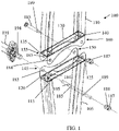
- FIG. 1 shows a perspective view of an exploded, truncated section of a beam system 100 comprising a first structural element 105 and a second structural element 110.
- the first structural element 105 comprises a first end (not shown) and a second end 115.
- the first structural element 105 is generally rectangular and the first end of the first structural element 105 is generally identical to the second end 115, which comprises an upper corner 120 and a lower corner 125.
- the second structural element 110 is also generally rectangular and comprises a first end 130 and a second end (not shown, but which is generally identical to the first end 130, but with a wider or narrower flange width to accommodate a reciprocal flange outside or inside the first flange).
- the first end 130 of the second structural element 110 comprises an upper corner 135 and a lower corner 140.
- the first and second structural elements 105, 110 define rectangular beams fabricated using any conventional beam materials and configurations such as steel tube stock, lengths of I-beam, or solid beam lengths. As will be appreciated by those skilled in the art, dimensions of the first and second structural elements 105, 110 can be varied to suit particular requirements for length, strength, beam moment of inertia, and other specifications as demanded by a particular application.
- the first structural element 105 and second structural element 110 each comprise clevis components 145, 150, 155, 160 at each of the upper and lower corners 120, 125, 135, 140.
- the first structural element 105 and the second structural element 110 are each attached to four clevis joints (as illustrated in FIG. 4 ). In FIG. 1 the clevis joints are shown in an exploded view to better illustrate the individual components.
- the clevis component 145 at the upper corner 120 of the second end 115 of the first structural element 105 is defined by a dual steel flange and is connected to the clevis component 155 at the upper corner 135 of the first end 130 of the second structural element 110. Further, the clevis component 150 at the lower corner 125 of the second end 115 of the first structural element 105 is connected to the clevis component 160 at the lower corner 140 of the first end 130 of the second structural element 110.
- a width between the dual flanges of the clevis component 145 can be slightly greater than a width between the dual flanges of the clevis component 155 to enable the clevis component 155 to fit into the clevis component 145.
- a clevis joint can be defined by a dual flange and a tang (not shown) positioned in the middle of the dual flange.
- Various other clevis joint configurations which allow rotation about some axes while restricting rotation about other axes, also may be used.
- each of the clevis joints comprises a clevis pin 185, a retainer (not shown) and a nut 187.
- Each clevis pin 185 is positioned in coaxially aligned holes 183, 184 and secures together two adjacent clevis components (such as the clevis components 145, 155).
- the retainer may include various types of fasteners such as a shaft locking pin, split cotter pin, an R-clip or a rivet, or a nut.
- a retainer such as an R-clip is positioned through holes 188 in the nut 187 and a hole 189 in the clevis pin 185 to secure the nut 187 to the pin 185.
- an end of a stabilising member 191 is used to secure a second end of a clevis pin 185.
- a retainer (not shown) is positioned through holes 194 in the stabilising member 191 and a hole 195 in the clevis pin 185.
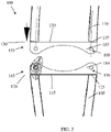
- FIG. 2 illustrates a front view of the exploded, truncated section of the beam system 100.
- FIG. 3 illustrates a side view of the exploded, truncated section of the beam system 100.
- the spacing between the dual flanges of the clevis component 145 is configured to receive the dual flanges of the clevis component 145.
- the elements shown in FIG. 3 define a clevis joint.
- the stabilising member 191 can be used to stabilise a supporting arch (which includes the first and second structural elements 105, 110) relative to an adjacent supporting arch.
- interconnecting the first structural element 105, the second structural element 110 and the stabilising member 191 can be done simply and easily and without the use of expensive machinery or highly skilled labour.
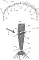
- FIG. 4 shows a front view of a plurality of beam systems 100, 101 connected together to form a supporting arch 400 in accordance with embodiments of the present invention.
- Structural elements 105, 110 defining beams systems 100 are aligned end to end and connected together using assembled clevis joints at upper corners 120, 135 and lower corners 125, 140, as described above.
- each structural element 105, 110 is secured by four assembled clevis joints, one at each corner of each structural element 105, 110.
- other structural elements 106, 111 defining lower, more curved beam systems 101 are also connected together and to the adjacent beam systems 100 to define the supporting arch 400.
- a combination of straight and curved structural elements can be used to define the outer shape of the supporting arch 400.
- all of the structural elements 105, 110 can be curved or all can be straight.
- curved structural members 105, 110 can result in an increase in the flexural strength of the supporting arch 100. A person skilled in the art will appreciate that this is important for large building structures that can be exposed to extreme weather conditions such as strong winds, heavy downpours and/or snow, which can subject the structures to considerable force.
- the supporting arch 400 is connected to a pair of footers 405, 410 at ground level
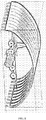
- FIG. 5 shows an exploded, truncated, perspective view of a lower section of the supporting arch 400 including the footer 405, in accordance with the present invention.
- a structural element 505 comprises three clevis components 510, 515, 520.
- the clevis component 510 is secured to a centre post 525 of the footer 405, and the clevis components 510, 520 are secured to an adjacent structural element 105 according to the teachings above.
- the stabilising member 191 (of which only one end is shown) is used to connect the supporting arch 400 to an adjacent, identical supporting arch 400 (not shown), where the two arches 400 are parallel to each other.
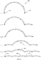
- FIG. 6 shows a front view of a construction plan illustrating a series of stages 1 to 6 for sequentially connecting five identical structural elements 605, together to erect a structural arch 600, according to a method of an embodiment of the present invention.
- the structural arch 600 is similar to the structural arch 400, but all of the structural elements 605 are identical.
- a first structural element 605 at the far left is first connected to a left footer 610, which can be similar to the footer 405. All five structural elements 605 are then laid on the ground, end to end, and upper clevis joints 615 on each element 605 are connected.
- the second and third elements 605 from the left are lifted and a lower clevis joint 620 is connected together to prevent further rotation of the second element 605 relative to the third element 605.
- "Dollies" and wheels combined with cables and winches can be used to pull the right most structural elements 605 horizontally toward the left most elements 605 to assist in erecting the arch 600.
- the ability to pull the structural elements 605 together horizontally to assist in lifting other structural elements 605 vertically enables the arch 600 to be raised without the use of large cranes or other overhead equipment.
- the process continues until the right most element 605 has moved fully to the left and is ready to be connected to a right footer 625.
- FIG. 7 illustrates a flow diagram of a method 700 for erecting the supporting arch 600, according to some embodiments.
- Block 705 comprises aligning the structural elements 605 that define a plurality of beam systems longitudinally (see Stage 1 of FIG. 6 ).
- Block 710 involves connecting together clevis components (similar to the clevis components 145, 155) at the upper corners of each of the structural elements 605, while leaving the clevis components at the lower corners unconnected.
- the structural elements 605 in a middle of the supporting arch 600 are elevated (see Stage 2 of FIG. 6 ).
- the clevis components at the lower corners of the structural elements 605 in the middle of the supporting arch 600 are then connected.
- roof sheeting such as sheet steel can be attached to the structural elements 605 at ground level before the structural elements 605 are elevated, where the roof sheeting extends across multiple, parallel supporting arches 600.
- the roof sheeting is then also lifted along with supporting arches during erection of a structure.
- the multiple, parallel supporting arches 600 are thus assembled and erected simultaneously, where each stage shown in FIG. 6 is completed on each of the multiple, parallel supporting arches 600 before advancing to the next stage.
- This can be very advantageous, as it avoids the requirement for specialised equipment for working at heights, such as cranes and scaffolding, and also avoids various risks associated with working at heights.
- the method 700 continues at block 725, where additional structural elements 605 are sequentially elevated (see Stage 3 of FIG. 6 ).
- block 730 the lower clevis joints 620 of additional elements 605 are connected together. Block 725 and block 730 are then repeated until the entire structural arch 600 is fully erected (see Stages 4 to 6 of FIG. 6 ). Once fully erected, the supporting arch 600 is connected to the right footer 625, as shown in FIG. 6 .
- FIG. 8 illustrates a perspective view of a completed airplane hanger constructed according to an embodiment of the present invention.
- the hanger comprises ten adjacent, parallel supporting arches that support a sheet steel roof that is 1,825mm high at its peak, 33,000mm long, and 47,650mm wide.
- FIG. 9 shows an elevated end view of the hanger shown in FIG. 8 .
- FIG. 10 shows a side view of a fully assembled clevis joint 1000, according to some embodiments of the present invention. Retainers in the form of shaft locking pins 1005 are shown securing together the assembled clevis joint 1000.
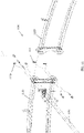
- FIG. 11 shows a perspective view of an exploded, truncated section of a beam system 1100 comprising a first structural element 1105 and a second structural element 1110, according to an alternative embodiment of the present invention.
- the structural elements 1105, 1110 are similar to the structural elements 105, 110; however, with the structural elements 1105, 1110 each clevis joint is connected together using two bolts rather than one. Each bolt is then held in place using a retainer such as an R-clip 1115 or a nut 1120.
- a stabilising member 1191 similar to the stabilising member 191, is also shown.
- advantages of embodiments of the present invention include a beam system which, in use, can be connected to further beam systems simply and quickly, and without the need for expensive tools and equipment, overhead cranes or skilled labour resources, to define a supporting arch that is connected to adjacent, parallel supporting arches of a roofed structure.
Landscapes
- Engineering & Computer Science (AREA)
- Architecture (AREA)
- Civil Engineering (AREA)
- Structural Engineering (AREA)
- Physics & Mathematics (AREA)
- Electromagnetism (AREA)
- Bridges Or Land Bridges (AREA)
- Rod-Shaped Construction Members (AREA)
Claims (13)
- Trägersystem, das Folgendes umfasst:ein erstes Strukturelement (105; 605; 1105); undein zweites Strukturelement (110; 605; 1110),wobei jedes des ersten und des zweiten Strukturelements ein erstes Ende (130) und ein zweites Ende (115) umfasst und jedes des ersten Endes und des zweiten Endes eine obere Ecke (120; 135) und eine untere Ecke (125; 140) umfasst und das Trägersystem einen Stützbogen (400) mit einer Vielzahl von Strukturelementen (105, 106, 110, 111; 605; 1105, 1110) definiert;jedes des ersten und des zweiten Strukturelements (105, 605; 110, 605, 1110) umfasst Schäkelkomponenten (145, 150; 155, 160) an jeder der oberen und der unteren Ecke; undeine Schäkelkomponente (145) an der oberen Ecke (120) des zweiten Endes (115) des ersten Strukturelements (105, 605, 1105) ist mit einer Schäkelkomponente (155) an der oberen Ecke (135) des ersten Endes (130) des zweiten Strukturelements (110, 605, 1110) verbunden, um eine erste Schäkelverbindung zu definieren, und eine Schäkelkomponente (150) an der unteren Ecke (125) des zweiten Endes (115) des ersten Strukturelements (105, 605, 1105) ist mit einer Schäkelkomponente (160) an der unteren Ecke (140) des ersten Endes (130) des zweiten Strukturelements (110, 605, 1110) verbunden, um eine zweite Schäkelverbindung zu definieren,wobei jede der Schäkelverbindungen einen Schäkelbolzen (185) mit einem ersten Loch (195) und einem zweiten Loch (189) umfasst;der Stützbogen (400; 600) ist mittels einer Vielzahl von Stabilisierungsgliedern (191) mit einem benachbarten Stützbogen verbindbar, wobei jedes Stabilisierungsglied (191) ein Loch (194) umfasst;eine Mutter (187) ist mit dem Schäkelbolzen (185) verbindbar, wobei die Mutter ein Loch (188) beinhaltet; unddadurch gekennzeichnet, dass ein distales Ende eines Stabilisierungsglieds (191) mit dem Schäkelbolzen (185) verbunden ist und eine der Schäkelverbindungen verbindet, dadurch, dass ein erster Halter durch das Loch (194) im Stabilisierungsglied (191) und durch das erste Loch (195) im Schäkelbolzen (185) angeordnet ist, und dadurch, dass ein zweiter Halter durch das Loch (188) in der Mutter (187) und durch das zweite Loch (189) im Schäkelbolzen (185) angeordnet ist.
- Trägersystem nach Anspruch 1, wobei die Schäkelkomponenten (145, 150; 155, 160) einen Doppelflansch oder eine Angel umfassen.
- Trägersystem nach Anspruch 1, wobei jede der Schäkelverbindungen entweder zwei aneinandergekoppelte Doppelflansche mit koaxial ausgerichteten Löchern (183) oder einen Doppelflansch und eine Angel mit koaxial ausgerichteten Löchern umfasst.
- Trägersystem nach Anspruch 1, wobei der Halter einen Wellenverriegelungsbolzen, einen geteilten Splint, einen R-Clip, einen Niet oder eine Mutter umfasst.
- Trägersystem nach Anspruch 1, wobei jeder der Schäkelbolzen (185) einen Wellenverriegelungsbolzen umfasst.
- Trägersystem nach Anspruch 1, wobei ein Flansch einer Schäkelverbindung an einer oberen Ecke (120; 135) integral mit einem Flansch einer Schäkelverbindung an einer benachbarten unteren Kante (125; 140) eines einzelnen Strukturelements gebildet ist.
- Trägersystem nach Anspruch 1, wobei das Trägersystem mindestens sechs Strukturelemente (105, 110; 605; 1105, 1110) beinhaltet.
- Trägersystem nach Anspruch 1, wobei der Stützbogen (400) mit einem Paar von Füßen (405, 410) verbunden ist.
- Trägersystem nach Anspruch 8, wobei jeder Fuß des Paares von Füßen (405, 410) mit einem Strukturelement verbunden ist, das drei Schäkelkomponenten umfasst.
- Trägersystem nach Anspruch 1, wobei sowohl das erste als auch das zweite Strukturelement (105; 110) gerade ist.
- Verfahren zum Aufstellen eines Stützbogens (400; 600) nach Anspruch 1, das Folgendes umfasst:Längsausrichten der Vielzahl von Strukturelementen (105, 106, 110, 111; 605; 1105, 1110);Verbinden von Schäkelkomponenten (145, 150, 155, 160) an den oberen Ecken der Vielzahl von Strukturelementen mit Schäkelkomponenten (145, 150, 155, 160) an benachbarten oberen Ecken von benachbarten Strukturelementen, bevor der Stützbogen (400) aufgestellt wird;Anheben von ersten und zweiten Strukturelementen (105, 605; 110, 605; 1105, 1110) in einer Mitte des Stützbogens (400), wobei die Schäkelkomponenten (145, 150, 155, 160) an den unteren Ecken (125; 140) der Vielzahl von Strukturelementen unverbunden bleiben;Verbinden von Schäkelkomponenten (145, 150, 155, 160) an den unteren Ecken des ersten und des zweiten Strukturelements unter Verwendung des Schäkelbolzens (185) mit Schäkelkomponenten (145, 150, 155, 160) an benachbarten unteren Ecken von benachbarten Strukturelementen;Verbinden des Stabilisierungsglieds (191) mit einem distalen Ende des Schäkelbolzens (185) durch Einsetzen des ersten Halters in das Loch (194) im Stabilisierungsglied (191) und in das erste Loch (195) im Schäkelbolzen (185);Verbinden der Mutter (187) mit einem proximalen Ende des Schäkelbolzens (185); undVerbinden des zweiten Halters durch das Loch (188) in der Mutter (187) und durch das zweite Loch (189) im Schäkelbolzen (185).
- Verfahren nach Anspruch 11, das vor dem Aufstellen der Strukturelemente ferner das Verbinden von Dachblechen mit der Vielzahl von Strukturelementen (105, 605; 110, 605; 1105, 1110) umfasst.
- Verfahren nach Anspruch 11, das ferner das horizontale Ziehen von einigen der Strukturelemente (605), um das vertikale Anheben von anderen Strukturelementen (605) zu unterstützen, umfasst.
Applications Claiming Priority (2)
| Application Number | Priority Date | Filing Date | Title |
|---|---|---|---|
| AU2015900830A AU2015900830A0 (en) | 2015-03-09 | Beam system and method of erecting a supporting arch | |
| PCT/AU2016/050168 WO2016141435A1 (en) | 2015-03-09 | 2016-03-09 | Beam system and method of erecting a supporting arch |
Publications (3)
| Publication Number | Publication Date |
|---|---|
| EP3268548A1 EP3268548A1 (de) | 2018-01-17 |
| EP3268548A4 EP3268548A4 (de) | 2018-12-19 |
| EP3268548B1 true EP3268548B1 (de) | 2022-07-27 |
Family
ID=56879830
Family Applications (1)
| Application Number | Title | Priority Date | Filing Date |
|---|---|---|---|
| EP16760938.7A Active EP3268548B1 (de) | 2015-03-09 | 2016-03-09 | Trägersystem und verfahren zur errichtung eines stützbogens |
Country Status (4)
| Country | Link |
|---|---|
| US (2) | US10260226B2 (de) |
| EP (1) | EP3268548B1 (de) |
| AU (2) | AU2016228964B2 (de) |
| WO (1) | WO2016141435A1 (de) |
Families Citing this family (9)
| Publication number | Priority date | Publication date | Assignee | Title |
|---|---|---|---|---|
| US20180155929A1 (en) * | 2016-12-02 | 2018-06-07 | Columbia Insurance Company | Masonry lintel for long spans |
| US10443239B2 (en) | 2016-12-02 | 2019-10-15 | Columbia Insurance Company | Long span masonry lintel support system |
| US20180245367A1 (en) * | 2017-02-28 | 2018-08-30 | Celina Tent, Inc. | Frame for a transportable shelter |
| US10480197B2 (en) | 2017-04-04 | 2019-11-19 | Columbia Insurance Company | Masonry support |
| CN109372124A (zh) * | 2018-11-07 | 2019-02-22 | 田同庆 | 大跨度筒壳网架安装工艺 |
| CN109518809B (zh) * | 2018-12-27 | 2024-01-09 | 上海市机械施工集团有限公司 | 一种三铰拱 |
| CL2019000711A1 (es) | 2019-02-20 | 2019-08-16 | Dsi Tunneling Llc | Sistema y procedimiento para soporte de tunel. |
| US10988921B1 (en) * | 2019-10-28 | 2021-04-27 | Overflow, Ltd. | Method and devices enabling rapid construction of buildings |
| CN110984456A (zh) * | 2019-11-07 | 2020-04-10 | 中建钢构有限公司 | 一种模块化的桁架屋盖结构及制造方法 |
Citations (1)
| Publication number | Priority date | Publication date | Assignee | Title |
|---|---|---|---|---|
| US4070846A (en) * | 1975-10-10 | 1978-01-31 | Pentti Aimo Johannes Sohlberg | Supporting framework for a shelter shed |
Family Cites Families (30)
| Publication number | Priority date | Publication date | Assignee | Title |
|---|---|---|---|---|
| DE268294C (de) * | 1910-03-15 | 1913-12-11 | ||
| US2399785A (en) * | 1943-08-13 | 1946-05-07 | American Rolling Mill Co | Metal hangar or similar building |
| US2965399A (en) * | 1959-02-19 | 1960-12-20 | Angelo A Rizzuto | Hinged butt joint |
| CH378519A (de) | 1960-04-21 | 1964-06-15 | Eggstein Julius | Zelthallenkonstruktion |
| US3557500A (en) * | 1968-07-26 | 1971-01-26 | Structex Corp | Foldable structure |
| US3785108A (en) * | 1972-01-06 | 1974-01-15 | Duraframe Syst Pty Ltd | Roof trusses |
| US4156433A (en) * | 1977-06-16 | 1979-05-29 | Rupp Industries Inc. | Portable shelter |
| US4244384A (en) * | 1979-03-07 | 1981-01-13 | Bean Garnet S | Modular shelter system |
| US4335555A (en) * | 1980-03-10 | 1982-06-22 | Robert D. Southerland | Rafter assembly and fixtures |
| AU556275B2 (en) * | 1984-11-29 | 1986-10-30 | High Accolade Limited | Post-tensioned steel frames and erection of such |
| US4673308A (en) * | 1985-11-29 | 1987-06-16 | Miranda Investments Limited | Hinge mechanism for use with folding structures |
| US5159790A (en) * | 1989-04-07 | 1992-11-03 | Harding Lewis R | Frame structure |
| WO1996001930A1 (en) * | 1994-07-11 | 1996-01-25 | Weatherhaven Resources Ltd. | Self-supporting collapsible covered frame structure |
| US5890339A (en) * | 1996-09-10 | 1999-04-06 | Alpine Engineered Products, Inc. | Hinged pitch break connector |
| US5983577A (en) * | 1997-02-19 | 1999-11-16 | Erecta Shelters, Inc. | Light weight pre-engineered prefabricated modular building system |
| US6401422B1 (en) * | 2000-02-04 | 2002-06-11 | Mitek Holdings, Inc. | Hinge and hinge joint for structural frame members |
| US20020116893A1 (en) * | 2001-02-27 | 2002-08-29 | Waldrop Billy B. | Metal framing strut with coiled end portions |
| AUPR690901A0 (en) * | 2001-08-09 | 2001-08-30 | Emms Investments Pty Ltd | A jointing device |
| US6928683B1 (en) * | 2002-06-25 | 2005-08-16 | Stuart Craig Hanson | Extendable support structures |
| CA2420345A1 (fr) * | 2003-03-07 | 2004-09-07 | Georges Bouchard | Abri telescopique |
| US7533498B2 (en) * | 2004-02-18 | 2009-05-19 | World Shelters, Inc. | Mechanically deployable expandable and collapsible structure and method for deploying a structure |
| WO2006007660A1 (en) * | 2004-07-21 | 2006-01-26 | Murray Ellen | Building methods |
| US7941983B2 (en) * | 2006-11-17 | 2011-05-17 | Flex-Ability Concepts, L.L.C. | Apparatus and methods of forming a curved structure |
| CA2720211C (en) * | 2008-04-11 | 2016-06-28 | Qld Steel Pty Ltd | Structural building components and method of constructing same |
| AU2010241246B2 (en) * | 2010-01-21 | 2014-12-04 | Pierre Camilleri | Building frame |
| US20110252717A1 (en) * | 2010-04-16 | 2011-10-20 | Graf Fernandez Rodrigo | Foldable structures for a construction |
| DE202011002901U1 (de) * | 2011-02-18 | 2012-05-21 | Kamal Daas | Gittertragwerk |
| US8813455B2 (en) * | 2011-12-07 | 2014-08-26 | Donald V. Merrifield | Deployable truss with orthogonally-hinged primary chords |
| US8869484B2 (en) * | 2012-11-13 | 2014-10-28 | Usg Interiors, Llc | Flexible drywall grid member for framing drywall structures |
| US9217248B2 (en) * | 2013-06-20 | 2015-12-22 | Morton Buildings, Inc. | Column assembly for use in building foundation systems and methods of assembling same |
-
2016
- 2016-03-09 EP EP16760938.7A patent/EP3268548B1/de active Active
- 2016-03-09 US US15/328,600 patent/US10260226B2/en active Active
- 2016-03-09 WO PCT/AU2016/050168 patent/WO2016141435A1/en not_active Ceased
- 2016-03-09 AU AU2016228964A patent/AU2016228964B2/en not_active Ceased
-
2019
- 2019-02-27 US US16/287,373 patent/US10683657B2/en active Active
-
2020
- 2020-08-07 AU AU2020213393A patent/AU2020213393B2/en not_active Ceased
Patent Citations (1)
| Publication number | Priority date | Publication date | Assignee | Title |
|---|---|---|---|---|
| US4070846A (en) * | 1975-10-10 | 1978-01-31 | Pentti Aimo Johannes Sohlberg | Supporting framework for a shelter shed |
Also Published As
| Publication number | Publication date |
|---|---|
| US20190194931A1 (en) | 2019-06-27 |
| WO2016141435A1 (en) | 2016-09-15 |
| US10260226B2 (en) | 2019-04-16 |
| AU2016228964A1 (en) | 2017-10-19 |
| AU2016228964B2 (en) | 2020-05-07 |
| EP3268548A1 (de) | 2018-01-17 |
| AU2020213393A1 (en) | 2020-08-27 |
| AU2020213393B2 (en) | 2021-09-23 |
| EP3268548A4 (de) | 2018-12-19 |
| US20170362812A1 (en) | 2017-12-21 |
| US10683657B2 (en) | 2020-06-16 |
Similar Documents
| Publication | Publication Date | Title |
|---|---|---|
| AU2020213393B2 (en) | Beam system and method of erecting a supporting arch | |
| US12037802B2 (en) | Erected platform and method of erecting thereof | |
| US10329781B2 (en) | Safety barrier netting system | |
| CN102191852B (zh) | 脚手架 | |
| US9528285B2 (en) | Safety barrier netting system with rigid panel net supports and stopper mechanisms | |
| US9861190B2 (en) | Wood gang form and method for constructing concrete building using same | |
| US9062448B2 (en) | Pivotally erectable structural frame system | |
| EP0237667A2 (de) | Gebäudebinder | |
| AU2022287672A1 (en) | Connection system | |
| WO2017140290A1 (de) | Fachwerktragsystem zum aufbau einer tragkonstruktion | |
| US11214955B2 (en) | Building construction | |
| DE102017114090B4 (de) | Verfahren zur Errichtung eines Gebäudes | |
| EP3306010A1 (de) | Schutz- und/oder arbeitsgerüst sowie verfahren zu dessen errichtung | |
| JPH0547704B2 (de) | ||
| US2307215A (en) | Building structure | |
| SG175872A1 (en) | Scaffolding system comprising a scaffolding element and method for erecting a scaffolding system | |
| US2752868A (en) | Roof construction | |
| EP0086201B1 (de) | Portalrahmen | |
| US20190024393A1 (en) | Modular scaffolding system | |
| US20240159042A1 (en) | System and method for lifting prejoined deck components | |
| AU2019253781B2 (en) | Relocatable buildings and associated systems and methods | |
| AU2019253877B2 (en) | Panelisation System and Method | |
| KR20110111086A (ko) | 표준규격 안전발판 설치용 서포트모듈 및 상기 모듈이 연속적으로 설치된 서포트모듈시스템 | |
| CN112482734A (zh) | 一种钢结构高空安全爬梯笼 | |
| Orton | The use of fast-fit connections for beam to tubular column joints |
Legal Events
| Date | Code | Title | Description |
|---|---|---|---|
| STAA | Information on the status of an ep patent application or granted ep patent |
Free format text: STATUS: THE INTERNATIONAL PUBLICATION HAS BEEN MADE |
|
| PUAI | Public reference made under article 153(3) epc to a published international application that has entered the european phase |
Free format text: ORIGINAL CODE: 0009012 |
|
| STAA | Information on the status of an ep patent application or granted ep patent |
Free format text: STATUS: REQUEST FOR EXAMINATION WAS MADE |
|
| 17P | Request for examination filed |
Effective date: 20170926 |
|
| AK | Designated contracting states |
Kind code of ref document: A1 Designated state(s): AL AT BE BG CH CY CZ DE DK EE ES FI FR GB GR HR HU IE IS IT LI LT LU LV MC MK MT NL NO PL PT RO RS SE SI SK SM TR |
|
| AX | Request for extension of the european patent |
Extension state: BA ME |
|
| DAV | Request for validation of the european patent (deleted) | ||
| DAX | Request for extension of the european patent (deleted) | ||
| A4 | Supplementary search report drawn up and despatched |
Effective date: 20181115 |
|
| RIC1 | Information provided on ipc code assigned before grant |
Ipc: E04B 7/08 20060101ALN20181109BHEP Ipc: E04B 1/35 20060101ALI20181109BHEP Ipc: E04B 1/32 20060101AFI20181109BHEP Ipc: E04C 3/11 20060101ALN20181109BHEP Ipc: E04B 1/24 20060101ALN20181109BHEP Ipc: E04H 3/14 20060101ALI20181109BHEP Ipc: E04B 1/342 20060101ALI20181109BHEP Ipc: E04C 3/40 20060101ALI20181109BHEP Ipc: E04H 6/44 20060101ALI20181109BHEP |
|
| STAA | Information on the status of an ep patent application or granted ep patent |
Free format text: STATUS: EXAMINATION IS IN PROGRESS |
|
| 17Q | First examination report despatched |
Effective date: 20201124 |
|
| GRAP | Despatch of communication of intention to grant a patent |
Free format text: ORIGINAL CODE: EPIDOSNIGR1 |
|
| STAA | Information on the status of an ep patent application or granted ep patent |
Free format text: STATUS: GRANT OF PATENT IS INTENDED |
|
| INTG | Intention to grant announced |
Effective date: 20210920 |
|
| GRAJ | Information related to disapproval of communication of intention to grant by the applicant or resumption of examination proceedings by the epo deleted |
Free format text: ORIGINAL CODE: EPIDOSDIGR1 |
|
| STAA | Information on the status of an ep patent application or granted ep patent |
Free format text: STATUS: EXAMINATION IS IN PROGRESS |
|
| GRAP | Despatch of communication of intention to grant a patent |
Free format text: ORIGINAL CODE: EPIDOSNIGR1 |
|
| STAA | Information on the status of an ep patent application or granted ep patent |
Free format text: STATUS: GRANT OF PATENT IS INTENDED |
|
| INTG | Intention to grant announced |
Effective date: 20220211 |
|
| GRAS | Grant fee paid |
Free format text: ORIGINAL CODE: EPIDOSNIGR3 |
|
| GRAA | (expected) grant |
Free format text: ORIGINAL CODE: 0009210 |
|
| STAA | Information on the status of an ep patent application or granted ep patent |
Free format text: STATUS: THE PATENT HAS BEEN GRANTED |
|
| AK | Designated contracting states |
Kind code of ref document: B1 Designated state(s): AL AT BE BG CH CY CZ DE DK EE ES FI FR GB GR HR HU IE IS IT LI LT LU LV MC MK MT NL NO PL PT RO RS SE SI SK SM TR |
|
| REG | Reference to a national code |
Ref country code: CH Ref legal event code: EP |
|
| REG | Reference to a national code |
Ref country code: DE Ref legal event code: R096 Ref document number: 602016073796 Country of ref document: DE |
|
| REG | Reference to a national code |
Ref country code: AT Ref legal event code: REF Ref document number: 1507160 Country of ref document: AT Kind code of ref document: T Effective date: 20220815 |
|
| REG | Reference to a national code |
Ref country code: IE Ref legal event code: FG4D |
|
| REG | Reference to a national code |
Ref country code: LT Ref legal event code: MG9D |
|
| REG | Reference to a national code |
Ref country code: NL Ref legal event code: MP Effective date: 20220727 |
|
| PG25 | Lapsed in a contracting state [announced via postgrant information from national office to epo] |
Ref country code: SE Free format text: LAPSE BECAUSE OF FAILURE TO SUBMIT A TRANSLATION OF THE DESCRIPTION OR TO PAY THE FEE WITHIN THE PRESCRIBED TIME-LIMIT Effective date: 20220727 Ref country code: RS Free format text: LAPSE BECAUSE OF FAILURE TO SUBMIT A TRANSLATION OF THE DESCRIPTION OR TO PAY THE FEE WITHIN THE PRESCRIBED TIME-LIMIT Effective date: 20220727 Ref country code: PT Free format text: LAPSE BECAUSE OF FAILURE TO SUBMIT A TRANSLATION OF THE DESCRIPTION OR TO PAY THE FEE WITHIN THE PRESCRIBED TIME-LIMIT Effective date: 20221128 Ref country code: NO Free format text: LAPSE BECAUSE OF FAILURE TO SUBMIT A TRANSLATION OF THE DESCRIPTION OR TO PAY THE FEE WITHIN THE PRESCRIBED TIME-LIMIT Effective date: 20221027 Ref country code: NL Free format text: LAPSE BECAUSE OF FAILURE TO SUBMIT A TRANSLATION OF THE DESCRIPTION OR TO PAY THE FEE WITHIN THE PRESCRIBED TIME-LIMIT Effective date: 20220727 Ref country code: LV Free format text: LAPSE BECAUSE OF FAILURE TO SUBMIT A TRANSLATION OF THE DESCRIPTION OR TO PAY THE FEE WITHIN THE PRESCRIBED TIME-LIMIT Effective date: 20220727 Ref country code: LT Free format text: LAPSE BECAUSE OF FAILURE TO SUBMIT A TRANSLATION OF THE DESCRIPTION OR TO PAY THE FEE WITHIN THE PRESCRIBED TIME-LIMIT Effective date: 20220727 Ref country code: FI Free format text: LAPSE BECAUSE OF FAILURE TO SUBMIT A TRANSLATION OF THE DESCRIPTION OR TO PAY THE FEE WITHIN THE PRESCRIBED TIME-LIMIT Effective date: 20220727 Ref country code: ES Free format text: LAPSE BECAUSE OF FAILURE TO SUBMIT A TRANSLATION OF THE DESCRIPTION OR TO PAY THE FEE WITHIN THE PRESCRIBED TIME-LIMIT Effective date: 20220727 |
|
| REG | Reference to a national code |
Ref country code: AT Ref legal event code: MK05 Ref document number: 1507160 Country of ref document: AT Kind code of ref document: T Effective date: 20220727 |
|
| PG25 | Lapsed in a contracting state [announced via postgrant information from national office to epo] |
Ref country code: PL Free format text: LAPSE BECAUSE OF FAILURE TO SUBMIT A TRANSLATION OF THE DESCRIPTION OR TO PAY THE FEE WITHIN THE PRESCRIBED TIME-LIMIT Effective date: 20220727 Ref country code: IS Free format text: LAPSE BECAUSE OF FAILURE TO SUBMIT A TRANSLATION OF THE DESCRIPTION OR TO PAY THE FEE WITHIN THE PRESCRIBED TIME-LIMIT Effective date: 20221127 Ref country code: HR Free format text: LAPSE BECAUSE OF FAILURE TO SUBMIT A TRANSLATION OF THE DESCRIPTION OR TO PAY THE FEE WITHIN THE PRESCRIBED TIME-LIMIT Effective date: 20220727 Ref country code: GR Free format text: LAPSE BECAUSE OF FAILURE TO SUBMIT A TRANSLATION OF THE DESCRIPTION OR TO PAY THE FEE WITHIN THE PRESCRIBED TIME-LIMIT Effective date: 20221028 |
|
| REG | Reference to a national code |
Ref country code: DE Ref legal event code: R082 Ref document number: 602016073796 Country of ref document: DE Representative=s name: CBDL PATENTANWAELTE GBR, DE Ref country code: DE Ref legal event code: R082 Ref document number: 602016073796 Country of ref document: DE Representative=s name: CBDL PATENTANWAELTE EGBR, DE |
|
| PG25 | Lapsed in a contracting state [announced via postgrant information from national office to epo] |
Ref country code: SM Free format text: LAPSE BECAUSE OF FAILURE TO SUBMIT A TRANSLATION OF THE DESCRIPTION OR TO PAY THE FEE WITHIN THE PRESCRIBED TIME-LIMIT Effective date: 20220727 Ref country code: RO Free format text: LAPSE BECAUSE OF FAILURE TO SUBMIT A TRANSLATION OF THE DESCRIPTION OR TO PAY THE FEE WITHIN THE PRESCRIBED TIME-LIMIT Effective date: 20220727 Ref country code: DK Free format text: LAPSE BECAUSE OF FAILURE TO SUBMIT A TRANSLATION OF THE DESCRIPTION OR TO PAY THE FEE WITHIN THE PRESCRIBED TIME-LIMIT Effective date: 20220727 Ref country code: CZ Free format text: LAPSE BECAUSE OF FAILURE TO SUBMIT A TRANSLATION OF THE DESCRIPTION OR TO PAY THE FEE WITHIN THE PRESCRIBED TIME-LIMIT Effective date: 20220727 Ref country code: AT Free format text: LAPSE BECAUSE OF FAILURE TO SUBMIT A TRANSLATION OF THE DESCRIPTION OR TO PAY THE FEE WITHIN THE PRESCRIBED TIME-LIMIT Effective date: 20220727 |
|
| REG | Reference to a national code |
Ref country code: DE Ref legal event code: R097 Ref document number: 602016073796 Country of ref document: DE |
|
| PG25 | Lapsed in a contracting state [announced via postgrant information from national office to epo] |
Ref country code: SK Free format text: LAPSE BECAUSE OF FAILURE TO SUBMIT A TRANSLATION OF THE DESCRIPTION OR TO PAY THE FEE WITHIN THE PRESCRIBED TIME-LIMIT Effective date: 20220727 Ref country code: EE Free format text: LAPSE BECAUSE OF FAILURE TO SUBMIT A TRANSLATION OF THE DESCRIPTION OR TO PAY THE FEE WITHIN THE PRESCRIBED TIME-LIMIT Effective date: 20220727 |
|
| PLBE | No opposition filed within time limit |
Free format text: ORIGINAL CODE: 0009261 |
|
| STAA | Information on the status of an ep patent application or granted ep patent |
Free format text: STATUS: NO OPPOSITION FILED WITHIN TIME LIMIT |
|
| PG25 | Lapsed in a contracting state [announced via postgrant information from national office to epo] |
Ref country code: AL Free format text: LAPSE BECAUSE OF FAILURE TO SUBMIT A TRANSLATION OF THE DESCRIPTION OR TO PAY THE FEE WITHIN THE PRESCRIBED TIME-LIMIT Effective date: 20220727 |
|
| 26N | No opposition filed |
Effective date: 20230502 |
|
| PG25 | Lapsed in a contracting state [announced via postgrant information from national office to epo] |
Ref country code: SI Free format text: LAPSE BECAUSE OF FAILURE TO SUBMIT A TRANSLATION OF THE DESCRIPTION OR TO PAY THE FEE WITHIN THE PRESCRIBED TIME-LIMIT Effective date: 20220727 |
|
| PG25 | Lapsed in a contracting state [announced via postgrant information from national office to epo] |
Ref country code: MC Free format text: LAPSE BECAUSE OF FAILURE TO SUBMIT A TRANSLATION OF THE DESCRIPTION OR TO PAY THE FEE WITHIN THE PRESCRIBED TIME-LIMIT Effective date: 20220727 |
|
| REG | Reference to a national code |
Ref country code: CH Ref legal event code: PL |
|
| GBPC | Gb: european patent ceased through non-payment of renewal fee |
Effective date: 20230309 |
|
| REG | Reference to a national code |
Ref country code: BE Ref legal event code: MM Effective date: 20230331 |
|
| PG25 | Lapsed in a contracting state [announced via postgrant information from national office to epo] |
Ref country code: LU Free format text: LAPSE BECAUSE OF NON-PAYMENT OF DUE FEES Effective date: 20230309 |
|
| REG | Reference to a national code |
Ref country code: IE Ref legal event code: MM4A |
|
| PG25 | Lapsed in a contracting state [announced via postgrant information from national office to epo] |
Ref country code: GB Free format text: LAPSE BECAUSE OF NON-PAYMENT OF DUE FEES Effective date: 20230309 |
|
| PG25 | Lapsed in a contracting state [announced via postgrant information from national office to epo] |
Ref country code: LI Free format text: LAPSE BECAUSE OF NON-PAYMENT OF DUE FEES Effective date: 20230331 Ref country code: IE Free format text: LAPSE BECAUSE OF NON-PAYMENT OF DUE FEES Effective date: 20230309 Ref country code: GB Free format text: LAPSE BECAUSE OF NON-PAYMENT OF DUE FEES Effective date: 20230309 Ref country code: FR Free format text: LAPSE BECAUSE OF NON-PAYMENT OF DUE FEES Effective date: 20230331 Ref country code: CH Free format text: LAPSE BECAUSE OF NON-PAYMENT OF DUE FEES Effective date: 20230331 |
|
| PG25 | Lapsed in a contracting state [announced via postgrant information from national office to epo] |
Ref country code: BE Free format text: LAPSE BECAUSE OF NON-PAYMENT OF DUE FEES Effective date: 20230331 |
|
| PG25 | Lapsed in a contracting state [announced via postgrant information from national office to epo] |
Ref country code: IT Free format text: LAPSE BECAUSE OF FAILURE TO SUBMIT A TRANSLATION OF THE DESCRIPTION OR TO PAY THE FEE WITHIN THE PRESCRIBED TIME-LIMIT Effective date: 20220727 |
|
| PGFP | Annual fee paid to national office [announced via postgrant information from national office to epo] |
Ref country code: DE Payment date: 20240409 Year of fee payment: 9 |
|
| PG25 | Lapsed in a contracting state [announced via postgrant information from national office to epo] |
Ref country code: BG Free format text: LAPSE BECAUSE OF FAILURE TO SUBMIT A TRANSLATION OF THE DESCRIPTION OR TO PAY THE FEE WITHIN THE PRESCRIBED TIME-LIMIT Effective date: 20220727 |
|
| PG25 | Lapsed in a contracting state [announced via postgrant information from national office to epo] |
Ref country code: BG Free format text: LAPSE BECAUSE OF FAILURE TO SUBMIT A TRANSLATION OF THE DESCRIPTION OR TO PAY THE FEE WITHIN THE PRESCRIBED TIME-LIMIT Effective date: 20220727 |
|
| PG25 | Lapsed in a contracting state [announced via postgrant information from national office to epo] |
Ref country code: CY Free format text: LAPSE BECAUSE OF FAILURE TO SUBMIT A TRANSLATION OF THE DESCRIPTION OR TO PAY THE FEE WITHIN THE PRESCRIBED TIME-LIMIT; INVALID AB INITIO Effective date: 20160309 |
|
| PG25 | Lapsed in a contracting state [announced via postgrant information from national office to epo] |
Ref country code: HU Free format text: LAPSE BECAUSE OF FAILURE TO SUBMIT A TRANSLATION OF THE DESCRIPTION OR TO PAY THE FEE WITHIN THE PRESCRIBED TIME-LIMIT; INVALID AB INITIO Effective date: 20160309 |
|
| REG | Reference to a national code |
Ref country code: DE Ref legal event code: R119 Ref document number: 602016073796 Country of ref document: DE |