EP3268253B1 - Hydraulic braking system - Google Patents
Hydraulic braking system Download PDFInfo
- Publication number
- EP3268253B1 EP3268253B1 EP16704797.6A EP16704797A EP3268253B1 EP 3268253 B1 EP3268253 B1 EP 3268253B1 EP 16704797 A EP16704797 A EP 16704797A EP 3268253 B1 EP3268253 B1 EP 3268253B1
- Authority
- EP
- European Patent Office
- Prior art keywords
- valve
- line
- control
- brake
- wheel brake
- Prior art date
- Legal status (The legal status is an assumption and is not a legal conclusion. Google has not performed a legal analysis and makes no representation as to the accuracy of the status listed.)
- Active
Links
- 238000009423 ventilation Methods 0.000 description 15
- 238000009987 spinning Methods 0.000 description 7
- 238000005520 cutting process Methods 0.000 description 5
- 238000004891 communication Methods 0.000 description 4
- 238000006073 displacement reaction Methods 0.000 description 4
- 230000001133 acceleration Effects 0.000 description 2
- 230000004913 activation Effects 0.000 description 2
- 230000000903 blocking effect Effects 0.000 description 2
- 238000010276 construction Methods 0.000 description 2
- 230000000712 assembly Effects 0.000 description 1
- 238000000429 assembly Methods 0.000 description 1
- 230000008878 coupling Effects 0.000 description 1
- 238000010168 coupling process Methods 0.000 description 1
- 238000005859 coupling reaction Methods 0.000 description 1
- 230000000994 depressogenic effect Effects 0.000 description 1
- 238000010586 diagram Methods 0.000 description 1
- 238000005516 engineering process Methods 0.000 description 1
- 238000011156 evaluation Methods 0.000 description 1
- 230000002706 hydrostatic effect Effects 0.000 description 1
- 238000004519 manufacturing process Methods 0.000 description 1
- 238000003825 pressing Methods 0.000 description 1
- 230000035484 reaction time Effects 0.000 description 1
- 244000037459 secondary consumers Species 0.000 description 1
Images


Classifications
-
- B—PERFORMING OPERATIONS; TRANSPORTING
- B60—VEHICLES IN GENERAL
- B60T—VEHICLE BRAKE CONTROL SYSTEMS OR PARTS THEREOF; BRAKE CONTROL SYSTEMS OR PARTS THEREOF, IN GENERAL; ARRANGEMENT OF BRAKING ELEMENTS ON VEHICLES IN GENERAL; PORTABLE DEVICES FOR PREVENTING UNWANTED MOVEMENT OF VEHICLES; VEHICLE MODIFICATIONS TO FACILITATE COOLING OF BRAKES
- B60T8/00—Arrangements for adjusting wheel-braking force to meet varying vehicular or ground-surface conditions, e.g. limiting or varying distribution of braking force
- B60T8/32—Arrangements for adjusting wheel-braking force to meet varying vehicular or ground-surface conditions, e.g. limiting or varying distribution of braking force responsive to a speed condition, e.g. acceleration or deceleration
- B60T8/34—Arrangements for adjusting wheel-braking force to meet varying vehicular or ground-surface conditions, e.g. limiting or varying distribution of braking force responsive to a speed condition, e.g. acceleration or deceleration having a fluid pressure regulator responsive to a speed condition
- B60T8/48—Arrangements for adjusting wheel-braking force to meet varying vehicular or ground-surface conditions, e.g. limiting or varying distribution of braking force responsive to a speed condition, e.g. acceleration or deceleration having a fluid pressure regulator responsive to a speed condition connecting the brake actuator to an alternative or additional source of fluid pressure, e.g. traction control systems
- B60T8/4809—Traction control, stability control, using both the wheel brakes and other automatic braking systems
- B60T8/4827—Traction control, stability control, using both the wheel brakes and other automatic braking systems in hydraulic brake systems
-
- B—PERFORMING OPERATIONS; TRANSPORTING
- B60—VEHICLES IN GENERAL
- B60T—VEHICLE BRAKE CONTROL SYSTEMS OR PARTS THEREOF; BRAKE CONTROL SYSTEMS OR PARTS THEREOF, IN GENERAL; ARRANGEMENT OF BRAKING ELEMENTS ON VEHICLES IN GENERAL; PORTABLE DEVICES FOR PREVENTING UNWANTED MOVEMENT OF VEHICLES; VEHICLE MODIFICATIONS TO FACILITATE COOLING OF BRAKES
- B60T8/00—Arrangements for adjusting wheel-braking force to meet varying vehicular or ground-surface conditions, e.g. limiting or varying distribution of braking force
- B60T8/32—Arrangements for adjusting wheel-braking force to meet varying vehicular or ground-surface conditions, e.g. limiting or varying distribution of braking force responsive to a speed condition, e.g. acceleration or deceleration
- B60T8/34—Arrangements for adjusting wheel-braking force to meet varying vehicular or ground-surface conditions, e.g. limiting or varying distribution of braking force responsive to a speed condition, e.g. acceleration or deceleration having a fluid pressure regulator responsive to a speed condition
- B60T8/343—Systems characterised by their lay-out
- B60T8/344—Hydraulic systems
- B60T8/345—Hydraulic systems having more than one brake circuit per wheel
-
- B—PERFORMING OPERATIONS; TRANSPORTING
- B60—VEHICLES IN GENERAL
- B60T—VEHICLE BRAKE CONTROL SYSTEMS OR PARTS THEREOF; BRAKE CONTROL SYSTEMS OR PARTS THEREOF, IN GENERAL; ARRANGEMENT OF BRAKING ELEMENTS ON VEHICLES IN GENERAL; PORTABLE DEVICES FOR PREVENTING UNWANTED MOVEMENT OF VEHICLES; VEHICLE MODIFICATIONS TO FACILITATE COOLING OF BRAKES
- B60T8/00—Arrangements for adjusting wheel-braking force to meet varying vehicular or ground-surface conditions, e.g. limiting or varying distribution of braking force
- B60T8/32—Arrangements for adjusting wheel-braking force to meet varying vehicular or ground-surface conditions, e.g. limiting or varying distribution of braking force responsive to a speed condition, e.g. acceleration or deceleration
- B60T8/34—Arrangements for adjusting wheel-braking force to meet varying vehicular or ground-surface conditions, e.g. limiting or varying distribution of braking force responsive to a speed condition, e.g. acceleration or deceleration having a fluid pressure regulator responsive to a speed condition
- B60T8/36—Arrangements for adjusting wheel-braking force to meet varying vehicular or ground-surface conditions, e.g. limiting or varying distribution of braking force responsive to a speed condition, e.g. acceleration or deceleration having a fluid pressure regulator responsive to a speed condition including a pilot valve responding to an electromagnetic force
- B60T8/3615—Electromagnetic valves specially adapted for anti-lock brake and traction control systems
- B60T8/363—Electromagnetic valves specially adapted for anti-lock brake and traction control systems in hydraulic systems
- B60T8/3635—Electromagnetic valves specially adapted for anti-lock brake and traction control systems in hydraulic systems switching between more than two connections, e.g. 3/2-valves
-
- B—PERFORMING OPERATIONS; TRANSPORTING
- B60—VEHICLES IN GENERAL
- B60T—VEHICLE BRAKE CONTROL SYSTEMS OR PARTS THEREOF; BRAKE CONTROL SYSTEMS OR PARTS THEREOF, IN GENERAL; ARRANGEMENT OF BRAKING ELEMENTS ON VEHICLES IN GENERAL; PORTABLE DEVICES FOR PREVENTING UNWANTED MOVEMENT OF VEHICLES; VEHICLE MODIFICATIONS TO FACILITATE COOLING OF BRAKES
- B60T8/00—Arrangements for adjusting wheel-braking force to meet varying vehicular or ground-surface conditions, e.g. limiting or varying distribution of braking force
- B60T8/32—Arrangements for adjusting wheel-braking force to meet varying vehicular or ground-surface conditions, e.g. limiting or varying distribution of braking force responsive to a speed condition, e.g. acceleration or deceleration
- B60T8/34—Arrangements for adjusting wheel-braking force to meet varying vehicular or ground-surface conditions, e.g. limiting or varying distribution of braking force responsive to a speed condition, e.g. acceleration or deceleration having a fluid pressure regulator responsive to a speed condition
- B60T8/36—Arrangements for adjusting wheel-braking force to meet varying vehicular or ground-surface conditions, e.g. limiting or varying distribution of braking force responsive to a speed condition, e.g. acceleration or deceleration having a fluid pressure regulator responsive to a speed condition including a pilot valve responding to an electromagnetic force
- B60T8/3615—Electromagnetic valves specially adapted for anti-lock brake and traction control systems
- B60T8/3655—Continuously controlled electromagnetic valves
- B60T8/366—Valve details
- B60T8/3665—Sliding valves
-
- B—PERFORMING OPERATIONS; TRANSPORTING
- B60—VEHICLES IN GENERAL
- B60T—VEHICLE BRAKE CONTROL SYSTEMS OR PARTS THEREOF; BRAKE CONTROL SYSTEMS OR PARTS THEREOF, IN GENERAL; ARRANGEMENT OF BRAKING ELEMENTS ON VEHICLES IN GENERAL; PORTABLE DEVICES FOR PREVENTING UNWANTED MOVEMENT OF VEHICLES; VEHICLE MODIFICATIONS TO FACILITATE COOLING OF BRAKES
- B60T13/00—Transmitting braking action from initiating means to ultimate brake actuator with power assistance or drive; Brake systems incorporating such transmitting means, e.g. air-pressure brake systems
- B60T13/10—Transmitting braking action from initiating means to ultimate brake actuator with power assistance or drive; Brake systems incorporating such transmitting means, e.g. air-pressure brake systems with fluid assistance, drive, or release
- B60T13/12—Transmitting braking action from initiating means to ultimate brake actuator with power assistance or drive; Brake systems incorporating such transmitting means, e.g. air-pressure brake systems with fluid assistance, drive, or release the fluid being liquid
- B60T13/14—Transmitting braking action from initiating means to ultimate brake actuator with power assistance or drive; Brake systems incorporating such transmitting means, e.g. air-pressure brake systems with fluid assistance, drive, or release the fluid being liquid using accumulators or reservoirs fed by pumps
- B60T13/148—Arrangements for pressure supply
Definitions
- the invention relates to a power-assisted hydraulic brake system of a wheeled vehicle, with two brake circuits, each having a connectable via a brake valve with a pressurized flow line or with a non-return line main brake line and a plurality of these branching, each leading to a wheel brake cylinder a wheel brake, with a valve assembly an ABS control having at each wheel arranged in the respective wheel brake inlet valve with a parallel check valve and a leading from the respective wheel brake cylinder in a return line exhaust valve, and with a valve assembly of an ASR control, by means of a pressure line directly to the Main brake lines connectable and the return lines are shut off.
- a wheel-propelled power-assisted hydraulic brake system has two brake circuits, an antilock control (ABS TM) control valve assembly, and a traction control (ASR TM) valve assembly.
- the brake circuits each have an actuatable by a brake pedal brake valve, by means of which each one Main brake line, branch off from the more each leading to a wheel brake cylinder wheel brake wheel brake lines, to operate the wheel brakes with a pressurized flow line and to release the wheel brakes with a non-pressurized return line are connected.
- the valve assembly of the ABS control comprises a plurality of intake valves each having a parallel-connected, opening in the direction of the relevant main brake line check valve and a plurality of exhaust valves.
- an inlet valve with a check valve and an outlet valve leading from the respective wheel brake cylinder into a return line are arranged in the respective wheel brake line.
- the intake valves are open and the exhaust valves are closed.
- the inlet valve of the associated wheel brake cylinder is closed and the corresponding exhaust valve is opened, whereby the wheel brake of the relevant vehicle wheel is released.
- this pressure is reduced with the intake and exhaust valves closed via the check valve parallel to the intake valve.
- the ASR control also uses the intake and exhaust valves of the ABS control. If a spinning drive wheel is detected when starting or accelerating the wheeled vehicle by means of the vehicle wheels arranged speed sensors, a pressurized pressure line via the valve assembly of the ASR control directly, that is bypassing the brake valves, connected to the main brake lines of the two brake circuits and at the same time Return lines, which are connected via the brake valves to the main brake lines when the brake pedal is de-energized, shut off. Immediately before, the intake valves of the brake cylinders of the non-driven vehicle wheels and the non-spinning drive wheels are closed, so that only the wheel brake of the spinning drive wheel is operated.
- DE 195 46 056 A1 is a power-assisted hydraulic brake system of a motor vehicle with two brake circuits, an ABS control and an ASR control described.
- the relevant motor vehicle has by way of example a drive axle and a non-driven vehicle axle.
- the wheel brake cylinders of the wheel brakes are distributed diagonally on the two brake circuits.
- a pressure-carrying pressure line is provided, which leads bypassing the present in a metering valve combined brake valves from a pressure source with a branch to the wheel brake lines of the drive wheels.
- the valve arrangement of the ASR control comprises a check valve arranged in front of the branching in the pressure line and designed as a 2/2-way magnetic switching valve and two non-return valves arranged after the branching for feeding the pressure medium.
- a second embodiment according to the local there Fig. 2 has the valve assembly of the ASR control two arranged respectively after the branch in the pressure line branches, each designed as a 2/2-way magnetic switching valve check valves for feeding the pressure medium.
- both embodiments of the valve arrangement of the ASR control in each brake circuit arranged between the branch of the main brake line and the junction of the respective pressure line branch in the Radbrems effet, designed as a 2/2-way magnetic switching valve separating valve for preventing an outflow of the pressure medium ,
- the valve assembly comprises a single, designed as a 5/2-way magnetic switching valve ASR control valve via which the supply line of a brake circuit with a leading directly to the relevant main brake line bypass line and the return line of the same brake circuit can be shut off.
- the same function is in a second embodiment of the valve assembly according to the local there Fig. 2 with a designed as a 4/2-way solenoid switching valve ASR control valve.
- the ASR control valve arrangement assigned there comprises two each ASR control valves designed as a 2/2-way solenoid-switching valve.
- the one, in the unactuated state closed control valve is arranged in a bypass line, which leads from the supply line of a brake circuit directly to the relevant main brake line.
- the other open in the unactuated state control valve is arranged in the return line of the same brake circuit, which leads from the associated brake valve in a reservoir.
- the invention is therefore based on the object to propose a hydraulic brake system of the type mentioned, in which the ASR control includes the wheel brakes of both brake circuits, and the valve assembly of the ASR control in comparison with the known valve assemblies in conjunction with a high control dynamics control technology is simplified and less space takes up.
- valve assembly of the ASR control a single, as a Has 6/2-way magnetic switching valve trained ASR control valve, shut off in the unactuated state, a pressure-carrying main pressure line against two each directly leading to one of the main brake lines bypass lines and the two return lines are connected to a non-pressurized manifold, and on the actuated state in the Main pressure line connected to the two bypass lines and the two return lines are shut off against the manifold.
- the invention is therefore based on a known per se power-assisted hydraulic brake system of a wheeled vehicle, which has two brake circuits, each of which via a brake valve with a pressurized flow line or with a non-return line connectable main brake line and several branching from this, each to a wheel brake cylinder Have wheel brake leading wheel brake lines.
- the hydraulic brake system to a valve assembly of an ABS control, which has at each wheel arranged in the respective wheel brake inlet valve with a parallel check valve and leading from the respective wheel brake cylinder in a return line outlet valve.
- a valve arrangement of an ASR control is provided by means of the activation of a traction control system, a pressure-carrying pressure line directly, so bypassing the brake valves, connectable to the main brake lines and the outgoing of the brake valves return lines are shut off.
- the function of the valve assembly of the ASR control by a single, designed as a 6/2-way magnetic switching valve ASR control valve is met, which in the unactuated state, a pressure-carrying main pressure line against two each directly, so bypassing the respective brake valve to a the main brake lines leading bypass lines shut off and outgoing from the brake valves return lines are connected to a non-pressurized manifold, and connected via which in the actuated state, the main pressure line to the two bypass lines and the two return lines are shut off against the manifold.
- the ASR control valve of the ASR control is preferably designed as a slide valve having a control piston which is axially movable in a valve bore of a valve housing and has four control grooves, in which the connection of the main pressure line within the valve housing is branched into two switching channels which are radial in two spaced-apart axial positions open into the valve bore and are connected in the actuated state of the ASR control valve via two control grooves of the control piston, each with a connection channel of the bypass lines, and wherein the connection of the manifold within the valve housing is branched into two switching channels, which in two further spaced apart axial positions radially open into the valve bore and are connected in the unactuated state of the ASR control valve via two further control grooves of the control piston, each with a connection channel of the outgoing from the brake valves return lines.
- the volume flows to be switched and the required switching forces are relatively low.
- a relatively low control current is required to switch the ASR control valve by the energization of the electromagnet.
- the ASR control valve thereby has a high switching dynamics, ie short reaction times when switching on and off of the control current.
- control piston is relieved of pressure axially and radially, whereby lower switching forces are required and jamming of the control piston is avoided.
- the ASR control valve advantageously has two ventilation channels, which lead within the valve housing from both front ends of the valve bore to one of the switching channels of the manifold. Due to leakage in the front ends of the valve bore reaching pressure medium is thus pressed relatively little resistance in an axial displacement of the control piston in the ventilation channels and flows from there via the connection of the manifold back into the reservoir.
- control piston For its radial pressure relief of the control piston is advantageously provided with annular relief grooves, which are arranged at axial positions of the control piston, where in the unactuated or actuated state of the ASR control valve in each case a connection or switching channel outside the control grooves of the control piston opens into the valve bore.
- the voltage applied at the junction of the respective connection or switching channel in the valve bore pressure is circumferentially distributed by the respective relief groove, so that an effective radial force on the control piston and consequent increased friction between the control piston and the inner wall of the valve bore can be avoided.
- the intake valves and the exhaust valves of the ABS control are preferably designed as largely identical 2/2-way solenoid valves and arranged axially parallel to each wheel brake cylinder and together with the respective check valve in a valve block with a common valve housing.
- the intake valves and the exhaust valves are designed to increase the switching dynamics according to an embodiment of the invention as a slide valve with a valve in a valve bore of the valve housing axially movably guided control piston with a single cam, the connection of the output side leading directly to the wheel brake Section of Radbremstechnisch within the valve housing in two Branching is branched, which open radially in two spaced-apart axial positions in the valve bore of the intake valve or the exhaust valve, and of which one switching channel in the unactuated state of the intake valve via the associated control groove with a connection channel of the main brake line branching from the input side portion of the Radbrems effet and the other switching channel is connected in the actuated state of the exhaust valve via the associated control groove with a connection channel of a leading into the reservoir return line.
- these switching valves are designed to be axially and radially relieved of pressure.
- the inlet valve and the outlet valve each have two ventilation channels, which lead within the valve housing from both front ends of the respective valve bore to the connection channel of the return line. Due to leakage in the front ends of the valve holes reaching pressure medium is thus pressed relatively little resistance in an axial displacement of the respective control piston in the mentioned ventilation channels and flows from there via the connection of the return line back into the reservoir.
- control piston of the intake valve and the exhaust valve are advantageously each provided with a relief groove, which are each arranged at an axial position, in the actuated state of the intake valve and in the unactuated state of the exhaust valve in each case a connection or switching channel outside the control groove of the relevant control piston opens into the associated valve bore.
- the guided at the junction of the connection or switching channel in the respective valve bore pressure is distributed circumferentially by the relief groove, so that an effective radial force on the respective control piston and consequent increased friction between the respective control piston and the inner wall of the respective valve bore avoided become.
- the check valve via which a relative to the associated main brake line increased pressure in the respective wheel brake cylinder can be degraded, according to one embodiment in each case one of a valve spring against a valve seat pressed ball and is arranged in a valve bore of the valve housing, which within the valve housing end with the connection of the output-side portion of the Radbremstechnisch and outside of the valve seat, ie in the region of the valve spring, with the connection of the input-side portion of the Radbrems effet is in communication.
- the pressures prevailing in the wheel brake cylinders are advantageously sensed, which, according to one embodiment, is realized in that a pressure sensor is connected to each output-side section of a wheel brake line, which is connected to a control unit via a signal line ABS and ASR control is in communication.
- Fig. 8 is a principle known foreign-powered hydraulic brake system 1 'with two brake circuits 2, 3 of a wheeled vehicle with two vehicle axles shown in a schematic overview.
- Each of the two brake circuits 2, 3 has a main brake line 16, 17, to which two wheel brake cylinders 38, 39; 40, 41 not shown wheel brakes of vehicle wheels of the two vehicle axles are connected.
- the wheel brake cylinders 38, 39; 40, 41 axle wise, page by page or diagonally distributed to the brake circuits 2, 3.
- a mechanically actuated designed as a 3/3-way control valve brake valve 13, 14
- the main brake lines 16, 17 of the two brake circuits 2, 3 each with a pressurized feed line 7, 8 or a non-pressurized return line 11, 12 connectable.
- the two brake valves 13, 14 are mechanically coupled and actuated by means of a common brake pedal 15.
- the flow lines 7, 8 are connected to a common shut-off valve 6 ', in which limits the pressure of a funded by a pump 5 from a reservoir 4 pressure medium and excess pressure medium in a manner not shown via secondary consumers or directly into the reservoir 4 is returned.
- each flow line 7, 8 each have a pressure accumulator 9, 10 is connected.
- the return lines 11, 12 lead directly back into the reservoir 4.
- a more or less high pressure in the main brake lines 16, 17 is thus fed via the brake valves 13, 14.
- brake valves 13, 14 When releasing the brake pedal 15 and thus located in its rest position brake valves 13, 14 are the main brake lines 16, 17 with the associated return lines 11, 12 in conjunction and are then depressurized.
- the two main brake lines 16, 17 are each in two wheel brake lines 18, 19; 20, 21 branches, each to one of the wheel brake cylinder 38, 39; 40, 41 of the respective brake circuit 2, 3 lead.
- Each wheel brake line 18, 19; 20, 21 has two sections, denoted by the reference numerals 18a, 18b; 19a, 19b; 20a, 20b; 21a, 21b are marked.
- Between the two sections 18a, 18b; 19a, 19b; 20a, 20b; 21a, 21b of the wheel brake lines 18, 19; 20, 21 is each formed as a 2/2-way solenoid switching valve inlet valve 22, 23; 24, 25 are arranged, which are open in the unactuated, ie de-energized state.
- the inlet valves 22, 23; 24, 25 is in each case one in the direction of the respective main brake line 16, 17 opening check valve 26, 27; 28, 29 arranged in parallel.
- FIG. 1 is a circuit diagram of a hydraulic brake system 1 of a four-wheel drive wheeled vehicle shown on the hydraulic brake system 1 'according to Fig. 8 is based and a valve arrangement of an ASR control, so a traction control device is extended.
- the ASR control valve arrangement comprises a single ASR control valve 48 designed as a 6/2-way magnetic switching valve, via which, in the unactuated state, a pressurized main pressure line 47 is directed against two bypass lines 49, 50 leading directly to one of the main brake lines 16, 17 shut off and the outgoing of the two brake valves 13, 14 return lines 11, 12 are connected to a non-pressurized manifold 51, and via which in the actuated state, the main pressure line 47 connected to the two bypass lines 49, 50 and the two return lines 11, 12 against the manifold 51 are shut off.
- the main pressure line 47 is now connected to the shut-off valve 6, and the flow lines 7, 8 branch off from this main pressure line 47.
- the intake and exhaust valves 22, 23, 24, 25; 30, 31, 32, 33 and the check valves 26, 27, 28, 29 are presently summarized for each wheel brake cylinder 38, 39, 40, 41 in a structurally identical valve block 52, 53, 54, 55.
- a pressure sensor 56, 57, 58, 59 is connected to each of the output-side sections of the wheel brake lines 18b, 19b, 20b, 21b.
- the ASR control valve 48 and the pressure sensors 56, 57, 58, 59 as well as the inlet and outlet valves 22, 23, 24, 25; 30, 31, 32, 33 and the speed sensors 42, 43, 44, 45 are via electrical control and sensor lines, which in Fig. 1 shown as dash-dotted lines, connected to a common ABS and ASR control unit 60.
- the function of the hydraulic brake system 1 is identical to the hydraulic brake system 1 'according to Fig. 8 , Is during a startup or acceleration of the wheeled vehicle one of Speed sensors 42, 43, 44, 45 detected the spinning of a drive wheel, so the activation of the traction control initially, for example, the intake valves 23, 24, 25 of the non-spinning drive wheels closed and then the ASR control valve 48 is actuated, so switched.
- the bypass lines 49, 50 for feeding the pressure medium in the main pressure lines 16, 17 connected to the main pressure line 47 and the return lines 11, 12 for preventing an outflow of the pressure medium via the brake valves 13, 14 against the manifold 51 closed.
- the spinning drive wheel is decelerated by the operation of the associated wheel brake cylinder, here for example wheel brake cylinder 38.
- the recorded by the wheel brake in question is effective via the axle differential on the opposite drive wheel of the same drive axle as the drive torque, so that the wheeled vehicle can start or further accelerate.
- the brake pressure in the relevant wheel brake cylinder 38 is released again by the actuation of the associated intake and exhaust valves 22, 30.
- the traction control is terminated by the ASR control valve 48 and the inlet and outlet valves 22, 23, 24, 25; 30, 31, 32, 33 are de-energized and thereby return to their rest position.
- inlet valve for example, inlet valve 22
- the enclosed in the respective wheel brake cylinder 38 brake pressure is then reduced via the associated check valve 26.
- the ASR control valve 48 is formed as a spool valve having a control piston 63 axially movably guided in a valve bore 62 of a valve housing 61, to which four annular cam grooves 64, 65, 66, 67 are provided.
- the control piston 63 is by means of a magnet armature 70 of an electromagnet 68, whose magnetic coil 69 is connected via a cable 71 to the contacts of a socket 72, against the restoring force of an axially oppositely disposed valve spring 73 axially displaceable.
- the one in the cutting plane of Fig. 2 lying port 74 of the main pressure line 47 is branched within the valve housing 61 in two switching channels 76, 77 which open radially into the valve bore 62 in two spaced-apart axial positions and in the actuated state of the ASR control valve 48 via two control grooves 64, 65 of the control piston 63 with each a connection channel 79, 82 of the bypass lines 49, 50 are connected. While the first switching channel 76 is connected to the connection 74 of the main pressure line 47 via a connecting channel 75, the second switching channel 77 connects directly to this connection 74 as a coaxial extension.
- connection 80 of the second bypass line 50 which is parallel to the cutting plane of Fig. 3 arranged and therefore in Fig. 3 is shown only by dashed lines, via a coaxial connection channel 81 with the in the sectional plane according to Fig. 2 lying connection channel 82 is in communication.
- the one in the cutting plane of Fig. 3 lying terminal 83 of the manifold 51 is branched within the valve housing 61 in two switching channels 85, 86 which open into two further spaced axial positions radially into the valve bore 62 and in the unactuated state of the ASR control valve 48 via two further control grooves 66, 67 of the control piston 63, each having a connection channel 88, 90 of the brake valves 13, 14 outgoing return lines 11, 12 are connected.
- the first switching channel 85 is connected to the connection 83 of the collecting line 51 via a connecting channel 84
- the second switching channel 86 connects directly to this connection 83 as a coaxial extension.
- the in the sectional plane of Fig. 2 lying terminals 87, 89 of the two return lines 11, 12 each go directly into a coaxial connection channel 88, 90 via.
- the ASR control valve 48 has two ventilation channels 91, 92, which in the sectional plane of Fig. 3 lead inside the valve housing 61 from both front ends of the valve bore 62 to one of the switching channels 85, 86 of the manifold 51. Due to leakage in the front ends of the valve bore 62 reaching pressure medium is thus relatively low resistance in an axial displacement of the control piston 63 pressed into the ventilation channels 91, 92 and flows from there via the port 83 of the manifold 51 back into the reservoir. 4
- annular relief grooves 93, 94, 95, 96 which are arranged at axial positions at which in the unactuated or actuated state of the ASR control valve 48 each have a connection or switching channel 76, 77, 85, 90 outside the control grooves 64, 65, 66, 67 of the control piston 63 opens into the valve bore 62.
- the pressure applied to the mouth of the respective connection or switching channel 76, 77, 85, 90 in the valve bore 62 is circumferentially distributed by the respective relief groove 93, 94, 95, 96, so that an effective on the control piston 63 radial transverse force and a consequent increased friction between the control piston 63 and the inner wall of the valve bore 62 can be avoided.
- the inlet valve 22 and the outlet valve 30 are designed as substantially identical 2/2-way magnetic control valves, each with a single cam 101, 103, each as a slide valve with a in a valve bore 98, 99 of a common valve housing 97 axially movable control piston 100, executed and arranged axially parallel in the valve housing 97.
- the control pistons 100, 101 of the inlet valve 22 and the outlet valve 30 are connected in each case via a coupling rod with the armature 106, 112 of a respective associated electromagnet 104, 110.
- At the armature-distant axial end of the control piston 100, 102 acts on this in each case the restoring force of an associated valve spring 109, 115.
- the magnetic coil 105, 111 of the two electromagnets 104, 110 is connected via a respective cable 107, 113 with the contacts of a socket 108, 114.
- connection 116 of the output-side section 18b of the wheel brake line 18 is branched within the valve housing 97 into two switching channels 118, 119 which open radially into the valve bore 98, 99 of the inlet valve 22 or the outlet valve 30 in two spaced-apart axial positions.
- the in the sectional plane of Fig. 4 lying switching channels 118, 119 are connected via a connection channel 117 with the port 116 of the output-side portion 18b of the wheel brake line 18 in conjunction, which together with the coaxially arranged to this connection channel 117 in the sectional plane of Fig. 7 lies.
- the one switching channel 118 is connected in the unactuated state of the inlet valve 22 via the associated control groove 102 with a connection channel 121 of the main brake line 16 branching input side portion 18a of Radbrems Koch 18, in coaxial extension of the relevant terminal 120 in the sectional plane of Fig. 5 lies.
- the other switching channel 119 is connected in the actuated state of the outlet valve 30 via the associated control groove 103 with a connection channel 123 of the leading into the reservoir 4 return line 34, in coaxial extension of the relevant terminal 122 in the sectional plane of Fig. 6 lies.
- the check valve 26 has a of a valve spring 124 against a valve seat 126 depressed ball 125 and is in a in the sectional plane of Fig. 7 lying valve bore 127 of the valve housing 97 is arranged.
- This valve bore 127 opens at the end into an axially parallel to the valve holes 98, 99 of the inlet valve 22 and the outlet valve 30 disposed within the valve housing 97, via the connection channel 117 to the terminal 116 of the output-side portion 18b of the wheel brake line 18 communicating communication channel 128.
- the valve spring 124 outside of the valve seat 126 is the valve bore 127 of the check valve 26 via a further connecting channel 129 and the relevant connection channel 121 to the terminal 120 of the input-side portion 18a of the wheel brake line 18 in connection.
- the inlet valve 22 and the outlet valve 30 each have two ventilation channels 130, 131; 132, 133, which lead within the valve housing 97 from both front ends of the respective valve bore 98, 99 to the connection channel 123 of the return line 34.
- the inlet valve 22 and the outlet valve 30 each have two ventilation channels 130, 131; 132, 133, which lead within the valve housing 97 from both front ends of the respective valve bore 98, 99 to the connection channel 123 of the return line 34.
- control pistons 100, 102 of the inlet valve 22 and the outlet valve 30 are each provided with an annular relief groove 134, 136 for their radial pressure relief, which are each arranged at an axial position, at which in the actuated state of the inlet valve 22, the connection channel 121 of the input-side section 18a of the wheel brake line 18 and in the unactuated state of the exhaust valve 30 of the switching channel 119 of the output-side portion 18b of the wheel brake line 18 outside the control groove 101, 103 of the respective control piston 100, 102 opens into the associated valve bore 98, 99.
- the second to the control piston 100, 102 of the inlet valve 22 and the exhaust valve 30 existing. Ring grooves 135, 137 are due to the largely identical design of the valves 22, 30 and in the present case have no special function.
Description
Die Erfindung betrifft eine fremdkraftgestützte hydraulische Bremsanlage eines Radfahrzeugs, mit zwei Bremskreisen, die jeweils eine über ein Bremsventil mit einer druckführenden Vorlaufleitung oder mit einer drucklosen Rücklaufleitung verbindbare Hauptbremsleitung sowie mehrere von dieser abzweigende, jeweils zu einem Radbremszylinder einer Radbremse führende Radbremsleitungen aufweisen, mit einer Ventilanordnung einer ABS-Steuerung, die an jeder Radbremse ein in der betreffenden Radbremsleitung angeordnetes Einlassventil mit einem parallel geschalteten Rückschlagventil und ein von dem jeweiligen Radbremszylinder in eine Rücklaufleitung führendes Auslassventil aufweist, und mit einer Ventilanordnung einer ASR-Steuerung, mittels der eine Druckleitung unmittelbar mit den Hauptbremsleitungen verbindbar und die Rücklaufleitungen absperrbar sind.The invention relates to a power-assisted hydraulic brake system of a wheeled vehicle, with two brake circuits, each having a connectable via a brake valve with a pressurized flow line or with a non-return line main brake line and a plurality of these branching, each leading to a wheel brake cylinder a wheel brake, with a valve assembly an ABS control having at each wheel arranged in the respective wheel brake inlet valve with a parallel check valve and a leading from the respective wheel brake cylinder in a return line exhaust valve, and with a valve assembly of an ASR control, by means of a pressure line directly to the Main brake lines connectable and the return lines are shut off.
Während Personenfahrzeuge und leichte Nutzfahrzeuge üblicherweise eine pedalkraftgestützte hydraulische Bremsanlage und schwerere Nutzfahrzeuge eine fremdkraftgestützte pneumatische Bremsanlage aufweisen, können Radfahrzeuge, die, wie zum Beispiel Baumaschinen und Ackerschlepper, für einen Einsatz außerhalb befestigter Straßen und Wege vorgesehen sind, mit einer fremdkraftgestützten hydraulischen Bremsanlage ausgerüstet sein. Aufgrund der erforderlichen hohen Bremskräfte weisen die Radbremszylinder derartiger Radfahrzeuge ein relativ großes Verdrängungsvolumen auf, das nur mit einer fremdkraftgestützten Bremsanlage gefördert werden kann. Da Baumaschinen und Ackerschlepper üblicherweise über hydraulische Arbeitsgeräte verfügen oder sogar einen hydrostatischen Antrieb aufweisen, kann eine fremdkraftgestützte hydraulische Bremsanlage vorteilhaft die ohnehin vorhandene hydraulische Druckversorgungseinrichtung nutzen.While passenger cars and light commercial vehicles usually have a pedal-assisted hydraulic brake system and heavier commercial vehicles have a power-assisted pneumatic brake system, wheeled vehicles such as construction machines and farm tractors for use outside paved roads and lanes may be equipped with a power-assisted hydraulic brake system. Due to the required high braking forces, the wheel brake cylinder such wheeled vehicles on a relatively large displacement volume, which can be promoted only with a power-assisted braking system. Since construction machines and farm tractors usually have hydraulic implements or even have a hydrostatic drive, a power-assisted hydraulic brake system can advantageously use the already existing hydraulic pressure supply device.
Vorliegend wird von einer fremdkraftgestützten hydraulischen Bremsanlage eines Radfahrzeugs ausgegangen, die zwei Bremskreise, eine Ventilanordnung einer Blockierschutzsteuerung (ABS™-Steuerung), und eine Ventilanordnung einer Antriebsschlupfregelung (ASR™-Steuerung) aufweist. Die Bremskreise weisen jeweils ein durch ein Bremspedal betätigbares Bremsventil auf, mittels denen jeweils eine Hauptbremsleitung, von der mehrere jeweils zu einem Radbremszylinder einer Radbremse führende Radbremsleitungen abzweigen, zur Betätigung der Radbremsen mit einer druckführenden Vorlaufleitung und zum Lösen der Radbremsen mit einer drucklosen Rücklaufleitung verbindbar sind.In the present case, it is assumed that a wheel-propelled power-assisted hydraulic brake system has two brake circuits, an antilock control (ABS ™) control valve assembly, and a traction control (ASR ™) valve assembly. The brake circuits each have an actuatable by a brake pedal brake valve, by means of which each one Main brake line, branch off from the more each leading to a wheel brake cylinder wheel brake wheel brake lines, to operate the wheel brakes with a pressurized flow line and to release the wheel brakes with a non-pressurized return line are connected.
Die Ventilanordnung der ABS-Steuerung umfasst mehrere Einlassventile mit jeweils einem parallel geschalteten, in Richtung der betreffenden Hauptbremsleitung öffnenden Rückschlagventil und mehrere Auslassventile. An jeder Radbremse sind in der betreffenden Radbremsleitung ein Einlassventil mit einem Rückschlagventil und ein von dem jeweiligen Radbremszylinder in eine Rücklaufleitung führendes Auslassventil angeordnet. Im unbetätigten Zustand sind die Einlassventile geöffnet und die Auslassventile geschlossen. Wenn während eines Bremsvorgangs durch die Auswertung von an den Fahrzeugrädern angeordneten Drehzahlsensoren ein blockiertes oder ein vor dem Blockieren befindliches Fahrzeugrad festgestellt wird, wird das Einlassventil des zugeordneten Radbremszylinders geschlossen und das entsprechende Auslassventil geöffnet, wodurch die Radbremse des betreffenden Fahrzeugrades gelöst wird. Wenn zum Beispiel nach dem Lösen des Bremspedals in einem der Radbremszylinder ein höherer Druck als in der zugeordneten Hauptbremsleitung vorliegt, wird dieser Druck bei geschlossenen Einlass- und Auslassventilen über das dem Einlassventil parallel geschaltete Rückschlagventil abgebaut.The valve assembly of the ABS control comprises a plurality of intake valves each having a parallel-connected, opening in the direction of the relevant main brake line check valve and a plurality of exhaust valves. At each wheel brake, an inlet valve with a check valve and an outlet valve leading from the respective wheel brake cylinder into a return line are arranged in the respective wheel brake line. In the unactuated state, the intake valves are open and the exhaust valves are closed. If during a braking operation by the evaluation of arranged on the vehicle wheels speed sensors a blocked or located before blocking vehicle wheel is detected, the inlet valve of the associated wheel brake cylinder is closed and the corresponding exhaust valve is opened, whereby the wheel brake of the relevant vehicle wheel is released. If, for example, after release of the brake pedal in one of the wheel brake cylinders, a higher pressure than in the associated main brake line is present, this pressure is reduced with the intake and exhaust valves closed via the check valve parallel to the intake valve.
Die ASR-Steuerung greift ebenfalls auf die Einlass- und Auslassventile der ABS-Steuerung zurück. Wenn beim Anfahren oder Beschleunigen des Radfahrzeugs mittels den an den Fahrzeugrädern angeordneten Drehzahlsensoren ein durchdrehendes Antriebsrad festgestellt wird, wird eine druckführende Druckleitung über die Ventilanordnung der ASR-Steuerung unmittelbar, das heißt unter Umgehung der Bremsventile, mit den Hauptbremsleitungen der beiden Bremskreise verbunden und zugleich die Rücklaufleitungen, die bei unbetätigtem Bremspedal über die Bremsventile mit den Hauptbremsleitungen verbunden sind, abgesperrt. Unmittelbar vorher werden die Einlassventile der Bremszylinder der nicht angetriebenen Fahrzeugräder und der nicht durchdrehenden Antriebsräder geschlossen, so dass nur die Radbremse des durchdrehenden Antriebsrades betätigt wird. Durch das Abbremsen des durchdrehenden Antriebsrades wird das von der dortigen Radbremse aufgenommene Bremsmoment an dem gegenüberliegenden Antriebsrad derselben Antriebsachse über das Achsdifferenzial in gleicher Höhe als Antriebsmoment wirksam, wodurch das Radfahrzeug anfahren beziehungsweise weiter beschleunigen kann. Im Vergleich zu einem in einer Antriebsachse angeordneten Sperrdifferenzial, mit dem ein Traktionsverlust an einem Antriebsrad ebenfalls verhindert werden kann, stellt eine über einen aktiven Bremseingriff wirksame Antriebsschlupfregelung eine relativ einfache und deutlich kostengünstigere Einrichtung dar.The ASR control also uses the intake and exhaust valves of the ABS control. If a spinning drive wheel is detected when starting or accelerating the wheeled vehicle by means of the vehicle wheels arranged speed sensors, a pressurized pressure line via the valve assembly of the ASR control directly, that is bypassing the brake valves, connected to the main brake lines of the two brake circuits and at the same time Return lines, which are connected via the brake valves to the main brake lines when the brake pedal is de-energized, shut off. Immediately before, the intake valves of the brake cylinders of the non-driven vehicle wheels and the non-spinning drive wheels are closed, so that only the wheel brake of the spinning drive wheel is operated. By braking the spinning drive wheel is recorded by the local wheel brake torque at the opposite drive wheel of the same drive axle via the axle differential at the same height effective as a drive torque, whereby the wheeled vehicle can start or further accelerate. Compared to a arranged in a drive axle locking differential, with a loss of traction on a drive wheel can also be prevented, an effective over an active brake intervention traction control is a relatively simple and much cheaper device.
In der
Aus der
In einer dritten Ausführungsform gemäß der dortigen
Der Erfindung liegt daher die Aufgabe zugrunde, eine hydraulische Bremsanlage der eingangs genannten Art vorzuschlagen, bei welcher die ASR-Steuerung die Rad-bremsen beider Bremskreise einbezieht, und die Ventilanordnung der ASR-Steuerung im Vergleich mit den bekannten Ventilanordnungen in Verbindung mit einer hohen Steuerungsdynamik steuerungstechnisch vereinfacht ist sowie weniger Bauraum in Anspruch nimmt.The invention is therefore based on the object to propose a hydraulic brake system of the type mentioned, in which the ASR control includes the wheel brakes of both brake circuits, and the valve assembly of the ASR control in comparison with the known valve assemblies in conjunction with a high control dynamics control technology is simplified and less space takes up.
Diese Aufgabe ist in Verbindung mit den Merkmalen des Oberbegriffs des Anspruchs 1 dadurch gelöst, dass die Ventilanordnung der ASR-Steuerung ein einziges, als ein 6/2-Wege-Magnetschaltventil ausgebildetes ASR-Steuerventil aufweist, über das im unbetätigten Zustand eine druckführende Hauptdruckleitung gegen zwei jeweils unmittelbar zu einer der Hauptbremsleitungen führenden Bypassleitungen abgesperrt sowie die beiden Rücklaufleitungen mit einer drucklosen Sammelleitung verbunden sind, und über das im betätigten Zustand die Hauptdruckleitung mit den beiden Bypassleitungen verbunden sowie die beiden Rücklaufleitungen gegen die Sammelleitung abgesperrt sind.This object is achieved in conjunction with the features of the preamble of claim 1, characterized in that the valve assembly of the ASR control a single, as a
Die Erfindung geht demnach aus von einer an sich bekannten fremdkraftgestützten hydraulischen Bremsanlage eines Radfahrzeugs aus, die zwei Bremskreise aufweist, welche jeweils eine über ein Bremsventil mit einer druckführenden Vorlaufleitung oder mit einer drucklosen Rücklaufleitung verbindbare Hauptbremsleitung und mehrere von dieser abzweigende, jeweils zu einem Radbremszylinder einer Radbremse führende Radbremsleitungen aufweisen. Zudem weist die hydraulische Bremsanlage eine Ventilanordnung einer ABS-Steuerung auf, die an jeder Radbremse ein in der betreffenden Radbremsleitung angeordnetes Einlassventil mit einem parallel geschalteten Rückschlagventil und ein von dem jeweiligen Radbremszylinder in eine Rücklaufleitung führendes Auslassventil aufweist. Außerdem ist eine Ventilanordnung einer ASR-Steuerung vorgesehen, mittels der zur Aktivierung einer Antriebsschlupfregelung eine druckführende Druckleitung unmittelbar, also unter Umgehung der Bremsventile, mit den Hauptbremsleitungen verbindbar und die von den Bremsventilen ausgehenden Rücklaufleitungen absperrbar sind.The invention is therefore based on a known per se power-assisted hydraulic brake system of a wheeled vehicle, which has two brake circuits, each of which via a brake valve with a pressurized flow line or with a non-return line connectable main brake line and several branching from this, each to a wheel brake cylinder Have wheel brake leading wheel brake lines. In addition, the hydraulic brake system to a valve assembly of an ABS control, which has at each wheel arranged in the respective wheel brake inlet valve with a parallel check valve and leading from the respective wheel brake cylinder in a return line outlet valve. In addition, a valve arrangement of an ASR control is provided by means of the activation of a traction control system, a pressure-carrying pressure line directly, so bypassing the brake valves, connectable to the main brake lines and the outgoing of the brake valves return lines are shut off.
Erfindungsgemäß wird die Funktion der Ventilanordnung der ASR-Steuerung durch ein einziges, als ein 6/2-Wege-Magnetschaltventil ausgebildetes ASR-Steuerventil erfüllt, über welches im unbetätigten Zustand eine druckführende Hauptdruckleitung gegen zwei jeweils unmittelbar, also unter Umgehung des jeweiligen Bremsventils zu einer der Hauptbremsleitungen führenden Bypassleitungen abgesperrt sowie die von den Bremsventilen ausgehenden Rücklaufleitungen mit einer drucklosen Sammelleitung verbunden sind, und über welches im betätigten Zustand die Hauptdruckleitung mit den zwei Bypassleitungen verbunden sowie die beiden Rücklaufleitungen gegen die Sammelleitung abgesperrt sind.According to the invention, the function of the valve assembly of the ASR control by a single, designed as a 6/2-way magnetic switching valve ASR control valve is met, which in the unactuated state, a pressure-carrying main pressure line against two each directly, so bypassing the respective brake valve to a the main brake lines leading bypass lines shut off and outgoing from the brake valves return lines are connected to a non-pressurized manifold, and connected via which in the actuated state, the main pressure line to the two bypass lines and the two return lines are shut off against the manifold.
Zur Aktivierung der Antriebsschlupfregelung müssen somit außer der Betätigung des ASR-Steuerventils nur die Einlassventile der ABS-Steuerung der nicht zu betätigenden Radbremsen geschlossen werden. Durch die Betätigung beziehungsweise die Umschaltung des ASR-Steuerventils werden die Hauptbremsleitungen der beiden Bremskreise zur Einspeisung des Druckmittels mit der Hauptdruckleitung verbunden und die Rücklaufleitungen zur Verhinderung eines Abflusses des Druckmittels über die geöffneten Bremsventile abgesperrt. Eine entsprechende hydraulische Bremsanlage der eingangs genannten Art ohne eine ASR-Steuerung kann somit mit relativ einfachem steuerungstechnischen Aufwand und geringem zusätzlichen Platzbedarf um eine ASR-Steuerung erweitert werden.In order to activate the traction control, only the intake valves of the ABS control of the non-actuated wheel brakes must thus be closed except the operation of the ASR control valve. By actuating or switching the ASR control valve, the main brake lines of the two brake circuits are connected to the feed of the pressure medium to the main pressure line and shut off the return lines to prevent an outflow of the pressure medium through the open brake valves. A corresponding hydraulic brake system of the type mentioned without an ASR control can thus be extended with relatively simple control engineering effort and little additional space to an ASR control.
Das ASR-Steuerventil der ASR-Steuerung ist bevorzugt als ein Schieberventil mit einem in einer Ventilbohrung eines Ventilgehäuses axialbeweglich geführten Steuerkolben mit vier Steuernuten ausgebildet, bei dem der Anschluss der Hauptdruckleitung innerhalb des Ventilgehäuses in zwei Schaltkanäle verzweigt ist, welche in zwei voneinander beabstandeten Axialpositionen radial in die Ventilbohrung einmünden sowie im betätigten Zustand des ASR-Steuerventils über zwei Steuernuten des Steuerkolbens mit jeweils einem Anschlusskanal der Bypassleitungen verbunden sind, und bei dem der Anschluss der Sammelleitung innerhalb des Ventilgehäuses in zwei Schaltkanäle verzweigt ist, welche in zwei weiteren voneinander beabstandeten Axialpositionen radial in die Ventilbohrung einmünden sowie im unbetätigten Zustand des ASR-Steuerventils über zwei weitere Steuernuten des Steuerkolbens mit jeweils einem Anschlusskanal der von den Bremsventilen ausgehenden Rücklaufleitungen verbunden sind.The ASR control valve of the ASR control is preferably designed as a slide valve having a control piston which is axially movable in a valve bore of a valve housing and has four control grooves, in which the connection of the main pressure line within the valve housing is branched into two switching channels which are radial in two spaced-apart axial positions open into the valve bore and are connected in the actuated state of the ASR control valve via two control grooves of the control piston, each with a connection channel of the bypass lines, and wherein the connection of the manifold within the valve housing is branched into two switching channels, which in two further spaced apart axial positions radially open into the valve bore and are connected in the unactuated state of the ASR control valve via two further control grooves of the control piston, each with a connection channel of the outgoing from the brake valves return lines.
Aufgrund der ventilinternen Verzweigung der Anschlüsse der Hauptdruckleitung und der Sammelleitung sowie deren Schaltverbindung mit den Bypass- und Rücklaufleitungen über jeweils eine Steuernut des Steuerkolbens sind die zu schaltenden Volumenströme und die dafür erforderlichen Schaltkräfte relativ gering. Somit ist zum Umschalten des ASR-Steuerventils durch die Bestromung des Elektromagneten ein relativ niedriger Steuerstrom erforderlich. Ebenso weist das ASR-Steuerventil dadurch eine hohe Schaltdynamik, also kurze Reaktionszeiten beim Ein- und Ausschalten des Steuerstroms auf.Due to the valve-internal branching of the connections of the main pressure line and the manifold and their interconnection with the bypass and return lines via a respective control groove of the control piston, the volume flows to be switched and the required switching forces are relatively low. Thus, a relatively low control current is required to switch the ASR control valve by the energization of the electromagnet. Likewise, the ASR control valve thereby has a high switching dynamics, ie short reaction times when switching on and off of the control current.
Zur weiteren Erhöhung der Schaltdynamik des ASR-Steuerventils ist der Steuerkolben axial und radial druckentlastet, wodurch geringere Schaltkräfte erforderlich sind und ein Verklemmen des Steuerkolbens vermieden wird.To further increase the switching dynamics of the ASR control valve, the control piston is relieved of pressure axially and radially, whereby lower switching forces are required and jamming of the control piston is avoided.
Zur axialen Druckentlastung des Steuerkolbens weist das ASR-Steuerventil vorteilhaft zwei Belüftungskanäle auf, die innerhalb des Ventilgehäuses von beiden stirnseitigen Enden der Ventilbohrung zu jeweils einem der Schaltkanäle der Sammelleitung führen. Leckagebedingt in die stirnseitigen Enden der Ventilbohrung gelangendes Druckmittel wird somit bei einer Axialverschiebung des Steuerkolbens relativ widerstandsarm in die Belüftungskanäle gedrückt und strömt von dort über den Anschluss der Sammelleitung zurück in den Vorratsbehälter.For axial pressure relief of the control piston, the ASR control valve advantageously has two ventilation channels, which lead within the valve housing from both front ends of the valve bore to one of the switching channels of the manifold. Due to leakage in the front ends of the valve bore reaching pressure medium is thus pressed relatively little resistance in an axial displacement of the control piston in the ventilation channels and flows from there via the connection of the manifold back into the reservoir.
Zu seiner radialen Druckentlastung ist der Steuerkolben vorteilhaft mit ringförmigen Entlastungsnuten versehen, die an Axialpositionen des Steuerkolbens angeordnet sind, an denen im unbetätigten oder betätigten Zustand des ASR-Steuerventils jeweils ein Anschluss- oder Schaltkanal außerhalb der Steuernuten des Steuerkolbens in die Ventilbohrung einmündet. Der an der Einmündung des jeweiligen Anschluss- oder Schaltkanals in die Ventilbohrung anliegende Druck wird durch die jeweilige Entlastungsnut umfangsseitig verteilt, so dass eine auf den Steuerkolben wirksame radiale Querkraft sowie eine dadurch bedingte erhöhte Reibung zwischen dem Steuerkolben und der Innenwand der Ventilbohrung vermieden werden.For its radial pressure relief of the control piston is advantageously provided with annular relief grooves, which are arranged at axial positions of the control piston, where in the unactuated or actuated state of the ASR control valve in each case a connection or switching channel outside the control grooves of the control piston opens into the valve bore. The voltage applied at the junction of the respective connection or switching channel in the valve bore pressure is circumferentially distributed by the respective relief groove, so that an effective radial force on the control piston and consequent increased friction between the control piston and the inner wall of the valve bore can be avoided.
Zur Reduzierung des Fertigungs- und Montageaufwands sind die Einlassventile und die Auslassventile der ABS-Steuerung bevorzugt als weitgehend baugleiche 2/2-Wege-Magnetschaltventile ausgeführt sowie jeweils für jeden Radbremszylinder achsparallel und zusammen mit dem jeweiligen Rückschlagventil in einem Ventilblock mit einem gemeinsamen Ventilgehäuse angeordnet.To reduce the manufacturing and assembly costs, the intake valves and the exhaust valves of the ABS control are preferably designed as largely identical 2/2-way solenoid valves and arranged axially parallel to each wheel brake cylinder and together with the respective check valve in a valve block with a common valve housing.
Alternativ zu den sonst üblichen Sitzventilen sind die Einlassventile und die Auslassventile zur Erhöhung der Schaltdynamik gemäß einer Weiterbildung der Erfindung jeweils als ein Schieberventil mit einem in einer Ventilbohrung des Ventilgehäuses axialbeweglich geführten Steuerkolben mit einer einzigen Steuernut ausgebildet, deren Anschluss des unmittelbar zu dem Radbremszylinder führenden ausgangsseitigen Abschnitts der Radbremsleitung innerhalb des Ventilgehäuses jeweils in zwei Schaltkanäle verzweigt ist, welche in zwei voneinander beabstandeten Axialpositionen radial in die Ventilbohrung des Einlassventils oder des Auslassventils einmünden, und von denen der eine Schaltkanal im unbetätigten Zustand des Einlassventils über die zugeordnete Steuernut mit einem Anschlusskanal des von der Hauptbremsleitung abzweigenden eingangsseitigen Abschnitts der Radbremsleitung und der andere Schaltkanal im betätigten Zustand des Auslassventils über die zugeordnete Steuernut mit einem Anschlusskanal einer in den Vorratsbehälter führenden Rücklaufleitung verbunden ist.As an alternative to the usual seat valves, the intake valves and the exhaust valves are designed to increase the switching dynamics according to an embodiment of the invention as a slide valve with a valve in a valve bore of the valve housing axially movably guided control piston with a single cam, the connection of the output side leading directly to the wheel brake Section of Radbremsleitung within the valve housing in two Branching is branched, which open radially in two spaced-apart axial positions in the valve bore of the intake valve or the exhaust valve, and of which one switching channel in the unactuated state of the intake valve via the associated control groove with a connection channel of the main brake line branching from the input side portion of the Radbremsleitung and the other switching channel is connected in the actuated state of the exhaust valve via the associated control groove with a connection channel of a leading into the reservoir return line.
Um auch bei den Einlass- und Auslassventilen eine hohe Schaltdynamik für die ABS-Steuerung und die ASR-Steuerung zu erzielen, sind auch diese Schaltventile axial und radial druckentlastet ausgebildet.In order to achieve a high switching dynamics for the ABS control and the ASR control in the intake and exhaust valves, these switching valves are designed to be axially and radially relieved of pressure.
Zur axialen Druckentlastung des betreffenden Steuerkolbens weisen das Einlassventil und das Auslassventil gemäß einer vorteilhaften Weiterbildung jeweils zwei Belüftungskanäle auf, die innerhalb des Ventilgehäuses von beiden stirnseitigen Enden der jeweiligen Ventilbohrung zu dem Anschlusskanal der Rücklaufleitung führen. leckagebedingt in die stirnseitigen Enden der Ventilbohrungen gelangendes Druckmittel wird somit bei einer Axialverschiebung des jeweiligen Steuerkolbens relativ widerstandsarm in die erwähnten Belüftungskanäle gedrückt und strömt von dort über den Anschluss der Rücklaufleitung zurück in den Vorratsbehälter.For axial pressure relief of the respective control piston, the inlet valve and the outlet valve according to an advantageous development each have two ventilation channels, which lead within the valve housing from both front ends of the respective valve bore to the connection channel of the return line. Due to leakage in the front ends of the valve holes reaching pressure medium is thus pressed relatively little resistance in an axial displacement of the respective control piston in the mentioned ventilation channels and flows from there via the connection of the return line back into the reservoir.
Zu ihrer radialen Druckentlastung sind die Steuerkolben des Einlassventils und des Auslassventils vorteilhaft jeweils mit einer Entlastungsnut versehen, die jeweils an einer Axialposition angeordnet sind, an der im betätigten Zustand des Einlassventils und im unbetätigten Zustand des Auslassventils jeweils ein Anschluss- oder Schaltkanal außerhalb der Steuernut des betreffenden Steuerkolbens in die zugeordnete Ventilbohrung einmündet. Der an der Einmündung des Anschluss- oder Schaltkanals in die jeweilige Ventilbohrung geführte Druck wird durch die Entlastungsnut jeweils umfangsseitig verteilt, so dass eine auf den betreffenden Steuerkolben wirksame radiale Querkraft und eine dadurch bedingte erhöhte Reibung zwischen dem jeweiligen Steuerkolben sowie der Innenwand der betreffenden Ventilbohrung vermieden werden.To their radial pressure relief, the control piston of the intake valve and the exhaust valve are advantageously each provided with a relief groove, which are each arranged at an axial position, in the actuated state of the intake valve and in the unactuated state of the exhaust valve in each case a connection or switching channel outside the control groove of the relevant control piston opens into the associated valve bore. The guided at the junction of the connection or switching channel in the respective valve bore pressure is distributed circumferentially by the relief groove, so that an effective radial force on the respective control piston and consequent increased friction between the respective control piston and the inner wall of the respective valve bore avoided become.
Das Rückschlagventil, über das ein gegenüber der zugeordneten Hauptbremsleitung erhöhter Druck in dem betreffenden Radbremszylinder abgebaut werden kann, weist gemäß einer Ausführungsform jeweils eine von einer Ventilfeder gegen einen Ventilsitz gedrückte Kugel auf und ist in einer Ventilbohrung des Ventilgehäuses angeordnet, welche innerhalb des Ventilgehäuses endseitig mit dem Anschluss des ausgangsseitigen Abschnitts der Radbremsleitung und außerhalb des Ventilsitzes, also im Bereich der Ventilfeder, mit dem Anschluss des eingangsseitigen Abschnitts der Radbremsleitung in Verbindung steht.The check valve, via which a relative to the associated main brake line increased pressure in the respective wheel brake cylinder can be degraded, according to one embodiment in each case one of a valve spring against a valve seat pressed ball and is arranged in a valve bore of the valve housing, which within the valve housing end with the connection of the output-side portion of the Radbremsleitung and outside of the valve seat, ie in the region of the valve spring, with the connection of the input-side portion of the Radbremsleitung is in communication.
Zur weiteren Verbesserung der ABS- und ASR-Steuerung werden vorteilhaft die in den Radbremszylindern herrschenden Drücke sensorisch erfasst, was gemäß einer Ausführungsform dadurch realisiert ist, dass an jedem ausgangsseitigen Abschnitt einer Radbremsleitung jeweils ein Drucksensor angeschlossen ist, der über eine Signalleitung mit einem Steuergerät der ABS- und ASR-Steuerung in Verbindung steht.To further improve the ABS and ASR control, the pressures prevailing in the wheel brake cylinders are advantageously sensed, which, according to one embodiment, is realized in that a pressure sensor is connected to each output-side section of a wheel brake line, which is connected to a control unit via a signal line ABS and ASR control is in communication.
Zur weiteren Verdeutlichung der Erfindung ist der Beschreibung eine Zeichnung mit einem Ausführungsbeispiel beigefügt. In dieser zeigt
-
Fig. 1 eine erfindungsgemäße hydraulische Bremsanlage in einer schematischen Übersichtsdarstellung, -
Fig. 2 ein erfindungsgemäßes ASR-Steuerventil der hydraulischen Bremsanlage gemäßFig. 1 in einem ersten Längsschnitt, -
Fig. 3 das ASR-Steuerventil gemäßFig. 2 in einem zweiten Längsschnitt, -
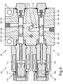
Fig. 4 einen ein Einlassventil, ein Auslassventil und ein Rückschlagventil umfassenden Ventilblock der hydraulischen Bremsanlage gemäßFig. 1 in einem ersten Längsschnitt, -
Fig. 5 das Einlassventil des Ventilblocks gemäßFig. 4 in einem zweiten Längsschnitt, -
Fig. 6 das Auslassventil des Ventilblocks gemäßFig. 4 in einem dritten Längsschnitt, -
Fig. 7 das Rückschlagventil des Ventilblocks gemäßFig. 4 in einem vierten Längsschnitt, und -
Fig. 8 eine als bekannt angesehene hydraulische Bremsanlage in einer schematischen Übersichtsdarstellung.
-
Fig. 1 a hydraulic brake system according to the invention in a schematic overview, -
Fig. 2 an inventive ASR control valve of the hydraulic brake system according toFig. 1 in a first longitudinal section, -
Fig. 3 the ASR control valve according toFig. 2 in a second longitudinal section, -
Fig. 4 a valve block comprising an intake valve, an exhaust valve and a check valve of the hydraulic brake system according toFig. 1 in a first longitudinal section, -
Fig. 5 the inlet valve of the valve block according toFig. 4 in a second longitudinal section, -
Fig. 6 the outlet valve of the valve block according toFig. 4 in a third longitudinal section, -
Fig. 7 the check valve of the valve block according toFig. 4 in a fourth longitudinal section, and -
Fig. 8 a hydraulic brake system considered as known in a schematic overview.
In
Jeder der beiden Bremskreise 2, 3 weist eine Hauptbremsleitung 16, 17 auf, an die jeweils zwei Radbremszylinder 38, 39; 40, 41 nicht näher dargestellter Radbremsen von Fahrzeugrädern der beiden Fahrzeugachsen angeschlossen sind. Bezüglich ihrer Anordnung an den Fahrzeugachsen können die Radbremszylinder 38, 39; 40, 41 achsweise, seitenweise oder diagonal auf die Bremskreise 2, 3 verteilt sein. Über jeweils ein mechanisch betätigbares, als ein 3/3-Wege-Regelventil ausgebildetes Bremsventil 13, 14 sind die Hauptbremsleitungen 16, 17 der beiden Bremskreise 2, 3 jeweils mit einer druckführenden Vorlaufleitung 7, 8 oder einer drucklosen Rücklaufleitung 11, 12 verbindbar. Die beiden Bremsventile 13, 14 sind mechanisch gekoppelt und mittels eines gemeinsamen Bremspedals 15 betätigbar.Each of the two
Die Vorlaufleitungen 7, 8 sind an ein gemeinsames Abschaltventil 6' angeschlossen, in dem der Druck eines von einer Pumpe 5 aus einem Vorratsbehälter 4 geförderten Druckmittels begrenzt und überschüssiges Druckmittel in nicht dargestellter Weise über Sekundärverbraucher oder unmittelbar in den Vorratsbehälter 4 zurückgeführt wird.The
An jede Vorlaufleitung 7, 8 ist jeweils ein Druckspeicher 9, 10 angeschlossen. Die Rücklaufleitungen 11, 12 führen unmittelbar zurück in den Vorratsbehälter 4. Abhängig von der Stellung des Bremspedals 15 wird somit über die Bremsventile 13, 14 ein mehr oder weniger hoher Druck in die Hauptbremsleitungen 16, 17 eingespeist. Bei losgelassenem Bremspedal 15 und somit in ihrer Ruhestellung befindlichen Bremsventilen 13, 14 stehen die Hauptbremsleitungen 16, 17 mit den zugeordneten Rücklaufleitungen 11, 12 in Verbindung und sind dann drucklos geschaltet.To each
Die beiden Hauptbremsleitungen 16, 17 sind jeweils in zwei Radbremsleitungen 18, 19; 20, 21 verzweigt, die jeweils zu einem der Radbremszylinder 38, 39; 40, 41 des jeweiligen Bremskreises 2, 3 führen. Jede Radbremsleitung 18, 19; 20, 21 weist zwei Abschnitte auf, welche mit den Bezugsziffern 18a, 18b; 19a, 19b; 20a, 20b; 21a, 21b gekennzeichnet sind. Zwischen den jeweils zwei Abschnitten 18a, 18b; 19a, 19b; 20a, 20b; 21a, 21b der Radbremsleitungen 18, 19; 20, 21 ist jeweils ein als ein 2/2-Wege-Magnetschaltventil ausgebildetes Einlassventil 22, 23; 24, 25 angeordnet, welche im unbetätigten, also stromlosen Zustand geöffnet sind. Den Einlassventilen 22, 23; 24, 25 ist jeweils ein in Richtung zu der jeweiligen Hauptbremsleitung 16, 17 öffnendes Rückschlagventil 26, 27; 28, 29 parallel geschaltet angeordnet.The two
An dem unmittelbar zu dem jeweiligen Radbremszylinder 38, 39; 40, 41 führenden ausgangsseitigen Abschnitt der Radbremsleitung 18b, 19b; 20b, 21b ist jeweils ein als ein 2/2-Wege-Magnetschaltventil ausgebildetes Auslassventil 30, 31; 32, 33 angeschlossen, von denen jeweils eine Rücklaufleitung 34, 35; 36, 37 in den Vorratsbehälter 4 führt, und die im unbetätigten, also im stromlosen Zustand geschlossen sind.At the directly to the respective
Die mit den parallel geschalteten Rückschlagventilen 26, 27; 28, 29 versehenen Einlassventile 22, 23; 24, 25 und die Auslassventile 30, 31; 32, 33 sind ebenso wie an den Fahrzeugrädern der beiden Fahrzeugachsen angeordnete Drehzahlsensoren 42, 42; 44, 45 Bestandteil einer ABS-Steuerung, welche über elektrische Steuer- und Sensorleitungen, die in
Wird während eines Bremsvorgangs durch Vergleich der mittels den Drehzahlsensoren 42, 43; 44, 45 erfassten Raddrehzahlen ein blockiertes oder vor dem Blockieren befindliches Fahrzeugrad erkannt, so wird der in dem betreffenden Radbremszylinder 38, 39; 40, 41 herrschende Druck durch das Schließen des zugeordneten Einlassventils 22, 23; 24, 25 und das Öffnen des zugeordneten Auslassventils 30, 31; 32, 33 zunächst abgesenkt sowie anschließend der Druck durch wechselweises Abschalten und Betätigen der Ein- und Auslassventile moduliert. Wenn sich dann durch ein Zurücknehmen des Bremspedals 15 in den Hauptbremsleitungen 16, 17 ein niedrigerer Druck einstellt, und bei geschlossenen Ein- und Auslassventilen in einem der Radbremszylinder 38, 39; 40, 41 ein höherer Druck als in der zugeordneten Hauptbremsleitung 16, 17 vorliegt, wird dieser Bremsdruck über das jeweils betreffende Rückschlagventil 26, 27; 28, 29 abgebaut.Is during a braking operation by comparing the means of the
In der schematischen Übersichtsdarstellung der
Die Ventilanordnung der ASR-Steuerung umfasst ein einziges, als ein 6/2-Wege-Magnetschaltventil ausgebildetes ASR-Steuerventil 48, über welches im unbetätigten Zustand eine druckführende Hauptdruckleitung 47 gegen zwei jeweils unmittelbar zu einer der Hauptbremsleitungen 16, 17 führenden Bypassleitungen 49, 50 abgesperrt und die von den beiden Bremsventilen 13, 14 ausgehenden Rücklaufleitungen 11, 12 mit einer drucklosen Sammelleitung 51 verbunden sind, und über welches im betätigten Zustand die Hauptdruckleitung 47 mit den beiden Bypassleitungen 49, 50 verbunden sowie die beiden Rücklaufleitungen 11, 12 gegen die Sammelleitung 51 abgesperrt sind.The ASR control valve arrangement comprises a single
Die Hauptdruckleitung 47 ist nun an das Abschaltventil 6 angeschlossen, und die Vorlaufleitungen 7, 8 zweigen von dieser Hauptdruckleitung 47 ab. Die Einlass- und Auslassventile 22, 23, 24, 25; 30, 31, 32, 33 sowie die Rückschlagventile 26, 27, 28, 29 sind vorliegend für jeden Radbremszylinder 38, 39, 40, 41 in einem baugleichen Ventilblock 52, 53, 54, 55 zusammengefasst.The
Zur genauen Erfassung der in den Radbremszylindern 38, 39, 40, 41 herrschenden Drücke ist an jeden der ausgangsseitigen Abschnitte der Radbremsleitungen 18b, 19b, 20b, 21b jeweils ein Drucksensor 56, 57, 58, 59 angeschlossen. Das ASR-Steuerventil 48 und die Drucksensoren 56, 57, 58, 59 sowie auch die Einlass- und Auslassventile 22, 23, 24, 25; 30, 31, 32, 33 und die Drehzahlsensoren 42, 43, 44, 45 sind über elektrische Steuer- und Sensorleitungen, die in
Bei unbetätigtem ASR-Steuerventil 48 ist die Funktion der hydraulischen Bremsanlage 1 identisch zu der hydraulischen Bremsanlage 1' gemäß
Sofern mittels den Drehzahlsensoren 42, 43, 44, 45 eine gewisse Beschleunigung des Radfahrzeugs und weitgehend gleiche Raddrehzahlen festgestellt werden, wird der Bremsdruck in dem betreffenden Radbremszylinder 38 durch die Betätigung der zugeordneten Einlass- und Auslassventile 22, 30 wieder abgelassen. Spätestens bei Betätigung der Bremsventile 13, 14 über das Bremspedal 15 wird die Antriebsschlupfregelung beendet, indem das ASR-Steuerventil 48 und die Einlass- und Auslassventile 22, 23, 24, 25; 30, 31, 32, 33 stromlos geschaltet werden und dadurch in ihre Ruhestellung zurückkehren. Bei einem gegebenenfalls in geschlossenem Zustand klemmenden Einlassventil, zum Beispiel Einlassventil 22, wird der in dem betreffenden Radbremszylinder 38 eingeschlossene Bremsdruck dann über das zugeordnete Rückschlagventil 26 abgebaut.If by means of the
Nachfolgend wird der Aufbau einer bevorzugten Ausführungsform des ASR-Steuerventils 48 anhand der in den
Das ASR-Steuerventil 48 ist als ein Schieberventil mit einem in einer Ventilbohrung 62 eines Ventilgehäuses 61 axialbeweglich geführten Steuerkolben 63 ausgebildet, an dem vier ringförmige Steuernuten 64, 65, 66, 67 vorhanden sind. Der Steuerkolben 63 ist mittels eines Magnetankers 70 eines Elektromagneten 68, dessen Magnetspule 69 über ein Kabel 71 mit den Kontakten einer Steckerbuchse 72 verbunden ist, gegen die Rückstellkraft einer axial gegenüberliegend angeordneten Ventilfeder 73 axial verschiebbar.The
Der in der Schnittebene von
Der in der Schnittebene von
Der in der Schnittebene von
Zur axialen Druckentlastung des Steuerkolbens 63 weist das ASR-Steuerventil 48 zwei Belüftungskanäle 91, 92 auf, die in der Schnittebene von
Zu seiner radialen Druckentlastung ist der Steuerkolben 63 mit ringförmigen Entlastungsnuten 93, 94, 95, 96 versehen, die an Axialpositionen angeordnet sind, an denen im unbetätigten oder betätigten Zustand des ASR-Steuerventils 48 jeweils ein Anschluss- oder Schaltkanal 76, 77, 85, 90 außerhalb der Steuernuten 64, 65, 66, 67 des Steuerkolbens 63 in die Ventilbohrung 62 einmündet. Der an der Einmündung des jeweiligen Anschluss- oder Schaltkanals 76, 77, 85, 90 in die Ventilbohrung 62 anliegende Druck wird durch die jeweilige Entlastungsnut 93, 94, 95, 96 umfangsseitig verteilt, so dass eine auf den Steuerkolben 63 wirksame radiale Querkraft und eine dadurch bedingte erhöhte Reibung zwischen dem Steuerkolben 63 und der Innenwand der Ventilbohrung 62 vermieden werden.For its radial pressure relief of the
Nachfolgend wird eine bevorzugte Ausführungsform der baugleichen Ventilblöcke 52, 53, 54, 55 am Beispiel des dem Radbremszylinder 38 zugeordneten Ventilblocks 52 anhand der in den
Das Einlassventil 22 und das Auslassventil 30 sind als weitgehend baugleiche 2/2-Wege-Magnetschaltventile ausgebildet, die jeweils als ein Schieberventil mit einem in einer Ventilbohrung 98, 99 eines gemeinsamen Ventilgehäuses 97 axialbeweglich geführten Steuerkolben 100, 102 mit einer einzigen Steuernut 101, 103 ausgeführt und achsparallel in dem Ventilgehäuse 97 angeordnet sind. Die Steuerkolben 100, 101 des Einlassventils 22 und des Auslassventils 30 sind über jeweils eine Koppelstange mit dem Magnetanker 106, 112 eines jeweils zugeordneten Elektromagneten 104, 110 verbunden. Am ankerfernen axialen Ende der Steuerkolben 100, 102 wirkt auf diese jeweils die Rückstellkraft einer zugeordneten Ventilfeder 109, 115. Die Magnetspule 105, 111 der beiden Elektromagneten 104, 110 ist über jeweils ein Kabel 107, 113 mit den Kontakten einer Steckerbuchse 108, 114 verbunden.The
Der Anschluss 116 des ausgangsseitigen Abschnitts 18b der Radbremsleitung 18 ist innerhalb des Ventilgehäuses 97 in zwei Schaltkanäle 118, 119 verzweigt, die in zwei voneinander beabstandeten Axialpositionen radial in die Ventilbohrung 98, 99 des Einlassventils 22 oder des Auslassventils 30 einmünden. Die in der Schnittebene von
Der eine Schaltkanal 118 ist im unbetätigten Zustand des Einlassventils 22 über die zugeordnete Steuernut 102 mit einem Anschlusskanal 121 des von der Hauptbremsleitung 16 abzweigenden eingangsseitigen Abschnitts 18a der Radbremsleitung 18 verbunden, der in koaxialer Verlängerung des betreffenden Anschlusses 120 in der Schnittebene von
Das Rückschlagventil 26 weist eine von einer Ventilfeder 124 gegen einen Ventilsitz 126 gedrückte Kugel 125 auf und ist in einer in der Schnittebene von
Analog zu dem ASR-Steuerventil 48 weisen das Einlassventil 22 und das Auslassventil 30 jeweils zwei Belüftungskanäle 130, 131; 132, 133 auf, die innerhalb des Ventilgehäuses 97 von beiden stirnseitigen Enden der jeweiligen Ventilbohrung 98, 99 zu dem Anschlusskanal 123 der Rücklaufleitung 34 führen. Hierzu münden die nahe der Schnittebene von
Ebenso sind die Steuerkolben 100, 102 des Einlassventils 22 und des Auslassventils 30 zu ihrer radialen Druckentlastung jeweils mit einer ringförmigen Entlastungsnut 134, 136 versehen, die jeweils an einer Axialposition angeordnet sind, an der im betätigten Zustand des Einlassventils 22 der Anschlusskanal 121 des eingangsseitigen Abschnitts 18a der Radbremsleitung 18 und im unbetätigten Zustand des Auslassventils 30 der Schaltkanal 119 des ausgangsseitigen Abschnitts 18b der Radbremsleitung 18 außerhalb der Steuernut 101, 103 des betreffenden Steuerkolbens 100, 102 in die zugeordnete Ventilbohrung 98, 99 einmündet. Die an den Steuerkolben 100, 102 des Einlassventils 22 und des Auslassventils 30 vorhandenen zweiten . Ringnuten 135, 137 sind auf die weitgehend baugleiche Ausführung der Ventile 22, 30 zurückzuführen und haben vorliegend keine besondere Funktion.Likewise, the
- 1, 1'1, 1 '
- Bremsanlagebraking system
- 22
- Erster BremskreisFirst brake circuit
- 33
- Zweiter BremskreisSecond brake circuit
- 44
- Vorratsbehälterreservoir
- 55
- Pumpepump
- 6, 6'6, 6 '
- Abschaltventilshut-off valve
- 77
- Vorlaufleitungsupply line
- 88th
- Vorlaufleitungsupply line
- 99
- Erster DruckspeicherFirst pressure accumulator
- 1010
- Zweiter DruckspeicherSecond pressure accumulator
- 1111
- Erste RücklaufleitungFirst return line
- 1212
- Zweite RücklaufleitungSecond return line
- 1313
- Bremsventilbrake valve
- 1414
- Bremsventilbrake valve
- 1515
- Bremspedalbrake pedal
- 1616
- Erste HauptbremsleitungFirst main brake line
- 1717
- Zweite HauptbremsleitungSecond main brake line
- 1818
- Radbremsleitungwheel brake
- 18a18a
- Eingangsseitiger Abschnitt von Radbremsleitung 18Input side section of wheel brake line 18
- 18b18b
- Ausgangsseitiger Abschnitt von Radbremsleitung 18Output side portion of wheel brake line 18
- 1919
- Radbremsleitungwheel brake
- 19a19a
- Eingangsseitiger Abschnitt von Radbremsleitung 19Input side section of wheel brake line 19
- 19b19b
- Ausgangsseitiger Abschnitt von Radbremsleitung 19Output side portion of wheel brake line 19
- 2020
- Radbremsleitungwheel brake
- 20a20a
- Eingangsseitiger Abschnitt von Radbremsleitung 20Entrance side portion of wheel brake line 20
- 20b20b
- Ausgangsseitiger Abschnitt von Radbremsleitung 20Output side portion of wheel brake line 20
- 2121
- Radbremsleitungwheel brake
- 21a21a
- Eingangsseitiger Abschnitt von Radbremsleitung 21Input side section of wheel brake line 21
- 21b21b
- Ausgangsseitiger Abschnitt von Radbremsleitung 21Output side portion of wheel brake line 21
- 2222
- Einlassventilintake valve
- 2323
- Einlassventilintake valve
- 2424
- Einlassventilintake valve
- 2525
- Einlassventilintake valve
- 2626
- Rückschlagventilcheck valve
- 2727
- Rückschlagventilcheck valve
- 2828
- Rückschlagventilcheck valve
- 2929
- Rückschlagventilcheck valve
- 3030
- Auslassventiloutlet valve
- 3131
- Auslassventiloutlet valve
- 3232
- Auslassventiloutlet valve
- 3333
- Auslassventiloutlet valve
- 3434
- RücklaufleitungReturn line
- 3535
- RücklaufleitungReturn line
- 3636
- RücklaufleitungReturn line
- 3737
- RücklaufleitungReturn line
- 3838
- Radbremszylinderwheel brake cylinder
- 3939
- Radbremszylinderwheel brake cylinder
- 4040
- Radbremszylinderwheel brake cylinder
- 4141
- Radbremszylinderwheel brake cylinder
- 4242
- DrehzahlsensorSpeed sensor
- 4343
- DrehzahlsensorSpeed sensor
- 4444
- DrehzahlsensorSpeed sensor
- 4545
- DrehzahlsensorSpeed sensor
- 4646
- ABS-SteuergerätABS control unit
- 4747
- HauptdruckleitungMain pressure line
- 4848
- ASR-SteuerventilASR control valve
- 4949
- Bypassleitungbypass line
- 5050
- Bypassleitungbypass line
- 5151
- Sammelleitungmanifold
- 5252
- Ventilblockmanifold
- 5353
- Ventilblockmanifold
- 5454
- Ventilblockmanifold
- 5555
- Ventilblockmanifold
- 5656
- Drucksensorpressure sensor
- 5757
- Drucksensorpressure sensor
- 5858
- Drucksensorpressure sensor
- 5959
- Drucksensorpressure sensor
- 6060
- Steuergerät der ABS- und ASR-SteuerungControl unit of the ABS and ASR control
- 6161
- Ventilgehäusevalve housing
- 6262
- Ventilbohrungvalve bore
- 6363
- Steuerkolbenspool
- 6464
- Steuernutcontrol groove
- 6565
- Steuernutcontrol groove
- 6666
- Steuernutcontrol groove
- 6767
- Steuernutcontrol groove
- 6868
- Elektromagnetelectromagnet
- 6969
- Magnetspulesolenoid
- 7070
- Magnetankerarmature
- 7171
- Kabelelectric wire
- 7272
- Steckerbuchsesocket
- 7373
- Ventilfedervalve spring
- 7474
-
Anschluss von Hauptdruckleitung 47Connection of
main pressure line 47 - 7575
- Verbindungskanalconnecting channel
- 7676
- Schaltkanalswitching channel
- 7777
- Schaltkanalswitching channel
- 7878
-
Anschluss von Bypassleitung 49Connection of
bypass line 49 - 7979
- Anschlusskanalconnecting channel
- 8080
-
Anschluss von Bypassleitung 50Connection of
bypass line 50 - 8181
- Verbindungskanalconnecting channel
- 8282
- Anschlusskanalconnecting channel
- 8383
-
Anschluss von Sammelleitung 51Connection of
manifold 51 - 8484
- Verbindungskanalconnecting channel
- 8585
- Schaltkanalswitching channel
- 8686
- Schaltkanalswitching channel
- 8787
-
Anschluss von Rücklaufleitung 11Connection of
return line 11 - 8888
- Anschlusskanalconnecting channel
- 8989
-
Anschluss von Rücklaufleitung 12Connection of
return line 12 - 9090
- Anschlusskanalconnecting channel
- 9191
- Belüftungskanalventilation duct
- 9292
- Belüftungskanalventilation duct
- 9393
- Entlastungsnutrelief
- 9494
- Entlastungsnutrelief
- 9595
- Entlastungsnutrelief
- 9696
- Entlastungsnutrelief
- 9797
- Ventilgehäusevalve housing
- 9898
- Ventilbohrungvalve bore
- 9999
- Ventilbohrungvalve bore
- 100100
- Steuerkolbenspool
- 101101
- Steuernutcontrol groove
- 102102
- Steuerkolbenspool
- 103103
- Steuernutcontrol groove
- 104104
- Elektromagnetelectromagnet
- 105105
- Magnetspulesolenoid
- 106106
- Magnetankerarmature
- 107107
- Kabelelectric wire
- 108108
- Steckerbuchsesocket
- 109109
- Ventilfedervalve spring
- 110110
- Elektromagnetelectromagnet
- 111111
- Magnetspulesolenoid
- 112112
- Magnetankerarmature
- 113113
- Kabelelectric wire
- 114114
- Steckerbuchsesocket
- 115115
- Ventilfedervalve spring
- 116116
-
Anschluss von ausgangsseitigem Abschnitt 18b von Radbremsleitung 18Connection of output-
side section 18 b of wheel brake line 18 - 117117
- Anschlusskanalconnecting channel
- 118118
- Schaltkanalswitching channel
- 119119
- Schaltkanalswitching channel
- 120120
-
Anschluss von eingangsseitigem Abschnitt 18a von Radbremsleitung 18Connection of input-
side section 18 a of wheel brake line 18 - 121121
- Anschlusskanalconnecting channel
- 122122
-
Anschluss von Rücklaufleitung 34Connection of
return line 34 - 123123
- Anschlusskanalconnecting channel
- 124124
- Ventilfedervalve spring
- 125125
- KugelBullet
- 126126
- Ventilsitzvalve seat
- 127127
- Ventilbohrungvalve bore
- 128128
- Verbindungskanalconnecting channel
- 129129
- Verbindungskanalconnecting channel
- 130130
- Belüftungskanalventilation duct
- 131131
- Belüftungskanalventilation duct
- 132132
- Belüftungskanalventilation duct
- 133133
- Belüftungskanalventilation duct
- 134134
- Entlastungsnutrelief
- 135135
- Ringnutring groove
- 136136
- Entlastungsnutrelief
- 137137
- Ringnutring groove
- ABSSECTION
- AntiblockiersystemAnti-lock braking system
- ASRASR
- AntriebsschlupfregelungDrive slip control
- ATCATC
- Automatic Traction ControlAutomatic Traction Control
- ECUECU
- Electronic Control UnitElectronic Control Unit
Claims (10)
- External force-supported hydraulic braking system (1) of a wheeled vehicle, comprising two brake circuits (2, 3) each having a main brake line (16, 17) that can be connected to a pressure-carrying supply line (7, 8) or to a pressureless return line (11, 12) via a brake valve (13, 14), and having a number of wheel brake lines (18a, 18b; 19a, 19b, 20a, 20b; 21a, 21b) branching from same and each leading to a wheel brake cylinder (38, 39, 40, 41) of a wheel brake, comprising a valve assembly of an ABS system which at each wheel brake has an inlet valve (22, 23, 24, 25), with a check valve (26, 27, 28, 29) connected in parallel, arranged in the corresponding wheel brake line, and an outlet valve (30, 31, 32, 33) leading from the respective wheel brake cylinder into a return line (34, 35, 36, 37), and comprising a valve assembly of a TCS system, by means of which a pressure line can be connected directly to the main brake lines (16, 17) and the return lines (11, 12) can be blocked, characterized in that the valve assembly of the TCS system has a single TCS control valve (48) formed as a 6/2-way magnetic switching valve, via which, in the non-actuated state, a pressure-carrying main pressure line (47) is blocked against two bypass lines (49, 50) each leading directly to a respective main brake line (16, 17), and the two return lines (11, 12) are connected to a pressureless collective line (51), and via which, in the actuated state, the main pressure line (47) is connected to the two bypass lines (49, 50) and the two return lines (11, 12) are blocked against the collective line (51).
- Braking system according to Claim 1, characterized in that the TCS control valve (48) is configured as a slide valve with a control piston (63) having four control grooves (64, 65, 66, 67) and guided so as to move axially in a valve bore (62) of a valve casing (61), that the port (74) of the main pressure line (47) branches inside the valve casing (61) into two switching channels (76, 77) which open radially into the valve bore (62) at two mutually spaced axial positions, and in the actuated state of the TCS control valve (48) are each connected via two control grooves (64, 65) of the control piston (63) to a respective joining channel (79, 82) of the bypass lines (49, 50), and that the port (83) of the collective line (51) branches inside the valve casing (61) into two switching channels (85, 86) which open radially into the valve bore (62) at two further mutually spaced axial positions, and in the non-actuated state of the TCS control valve (48) are each connected via two further control grooves (66, 67) of the control piston (63) to a respective joining channel (88, 90) of the return lines (11, 12) departing from the brake valves (13, 14).
- Braking system according to Claim 1 or 2, characterized in that for axial pressure relief of the control piston (63), the TCS control valve (48) has two vent channels (91, 92) which lead inside the valve casing (61) from the two end faces of the valve bore (62) to a respective switching channel (85, 86) of the collective line (51).
- Braking system according to any of Claims 1 to 3, characterized in that for radial pressure relief, the control piston (63) is provided with pressure relief grooves
(93, 94, 95, 96) arranged at axial positions at which, in non-actuated or actuated state of the TCS control valve (48), a respective joining or switching channel (76, 77, 85, 90) opens into the valve bore (62) outside the control grooves (64, 65, 66, 67) of the control piston. - Braking system according to any of Claims 1 to 4, characterized in that the inlet valves (22, 23, 24, 25) and the outlet valves (30, 31, 32, 33) of the ABS system are configured as 2/2-way magnetic switching valves, and for each wheel brake cylinder (38, 39, 40, 41) are arranged axially parallel and together with the respective check valve (26, 27, 28, 29) in a valve block (52, 53, 54, 55) with a common valve casing (97).
- Braking system according to Claim 5, characterized in that the inlet valves (22, 23, 24, 25) and the outlet valves (30, 31, 32, 33) are each configured as slide valves with a control piston (100, 102) having a single control groove (101, 103) and guided so as to move axially in a valve bore (98, 99) of the valve casing (97),
and that the port (116) of the output-side portion (18b) of the wheel brake line (18) branches inside the valve casing (97) into two switching channels (118, 119) which each open radially into the valve bore (98, 99) of the inlet valve (22) or outlet valve (30) respectively at two mutually spaced axial positions, and of which, in the non-actuated state of the inlet valve (22), the one switching channel (118) is connected via the assigned control groove (101) to a joining channel (121) of the input-side portion (18a) of the wheel brake line (18), and in the actuated state of the outlet valve (30), the other switching channel (119) is connected via the assigned control groove (103) to a joining channel (123) of a return line (34) leading to the storage container (4). - Braking system according to Claim 5 or 6, characterized in that for axial pressure relief of the respective control piston (100, 102), the inlet valve (22) and the outlet valve (30) each have two vent channels (130, 131; 132, 133) which lead inside the valve casing (97) from the two end faces of the respective valve bore (101, 103) to the joining channel (123) of the return line (34).
- Braking system according to any of Claims 5 to 7, characterized in that for radial pressure relief, the control pistons (100, 102) of the inlet valve (22) and the outlet valve (30) are each fitted with a pressure relief groove (134, 136) arranged at an axial position at which, in the actuated state of the inlet valve (22) and in the non-actuated state of the outlet valve (30), a joining or switching channel (119, 121) respectively opens into the assigned valve bore (98, 99) outside the control groove (101, 103) of the respective control piston (100, 102).
- Braking system according to any of Claims 5 to 8, characterized in that the check valve (26) has a ball (125) pressed by a valve spring (124) against the valve seat (126), and that the check valve (26) is arranged in a valve bore (127) of the valve casing (97) which is connected inside the valve casing (97) on the end side to the port (116) for the output-side portion (18b) of the wheel brake line (18) and outside the valve seat (126) to the port (120) for the input-side portion (18a) of the wheel brake line (18).
- Braking system according to any of Claims 1 to 9, characterized in that at each output-side portion (18b, 19b, 20b, 21b) of a wheel brake line (18a, 18b; 19a, 19b, 20a, 20b; 21a, 21b), a pressure sensor (56, 57, 58, 59) is connected which is connected via a signal line to a control unit (60) of the ABS and TCS system.
Applications Claiming Priority (2)
| Application Number | Priority Date | Filing Date | Title |
|---|---|---|---|
| DE102015003201.1A DE102015003201A1 (en) | 2015-03-10 | 2015-03-10 | Hydraulic brake system |
| PCT/EP2016/000230 WO2016142028A1 (en) | 2015-03-10 | 2016-02-11 | Hydraulic braking system |
Publications (2)
| Publication Number | Publication Date |
|---|---|
| EP3268253A1 EP3268253A1 (en) | 2018-01-17 |
| EP3268253B1 true EP3268253B1 (en) | 2019-04-10 |
Family
ID=55361456
Family Applications (1)
| Application Number | Title | Priority Date | Filing Date |
|---|---|---|---|
| EP16704797.6A Active EP3268253B1 (en) | 2015-03-10 | 2016-02-11 | Hydraulic braking system |
Country Status (5)
| Country | Link |
|---|---|
| US (1) | US10086812B2 (en) |
| EP (1) | EP3268253B1 (en) |
| JP (1) | JP2018509331A (en) |
| DE (1) | DE102015003201A1 (en) |
| WO (1) | WO2016142028A1 (en) |
Families Citing this family (2)
| Publication number | Priority date | Publication date | Assignee | Title |
|---|---|---|---|---|
| GB2563238B (en) * | 2017-06-07 | 2021-04-28 | Caterpillar Sarl | Fluid delivery system |
| EP3747716B1 (en) * | 2019-06-03 | 2023-09-13 | Haldex Brake Products Aktiebolag | Pneumatic vehicle axle brake assembly |
Family Cites Families (13)
| Publication number | Priority date | Publication date | Assignee | Title |
|---|---|---|---|---|
| DE3714740A1 (en) * | 1987-05-02 | 1988-11-17 | Teves Gmbh Alfred | Motor vehicle brake system with slip control |
| DE3900852C1 (en) | 1989-01-13 | 1990-03-01 | Daimler-Benz Aktiengesellschaft, 7000 Stuttgart, De | |
| DE4106336A1 (en) * | 1991-02-28 | 1992-09-03 | Bosch Gmbh Robert | HYDRAULIC BRAKE SYSTEM, ESPECIALLY FOR MOTOR VEHICLES |
| US5855417A (en) * | 1994-09-12 | 1999-01-05 | General Motors Corporation | Integral control and isolation valve proportional brake system |
| DE19546056A1 (en) | 1995-12-09 | 1997-06-12 | Teves Gmbh Alfred | Hydraulic brake system with high pressure source and pedal operated metering valve |
| US6053582A (en) * | 1996-08-14 | 2000-04-25 | Kelsey-Hayes Company | Integrated ABS/TC/VSC braking system with separate boost valve |
| US5984432A (en) * | 1997-03-14 | 1999-11-16 | Toyota Jidosha Kabushiki Kaisha | Pressure control apparatus including seating valve controlled by electric current incremented upon valve opening depending upon pressure difference across the valve |
| US6196642B1 (en) * | 1997-05-02 | 2001-03-06 | Akebono Brake Industry Co., Ltd. | Four-piston brake fluid pressure controller with diaphragm |
| DE19859737A1 (en) | 1998-12-23 | 2000-06-29 | Wabco Gmbh & Co Ohg | Hydraulic brake system |
| FR2843926B1 (en) | 2002-09-02 | 2005-05-20 | Poclain Hydraulics Ind | ANTI-SKIN AND ANTI-BLOCKING DEVICE FOR WHEELS OF A VEHICLE USING THE BRAKING CIRCUIT |
| US7325883B2 (en) * | 2004-10-04 | 2008-02-05 | Continental Teves, Inc. | Hydraulic braking system featuring selectively-coupled pump suction circuits |
| WO2009043343A1 (en) | 2007-10-05 | 2009-04-09 | Robert Bosch Gmbh | Hydraulic power brake system |
| WO2009138075A1 (en) | 2008-05-14 | 2009-11-19 | Robert Bosch Gmbh | Hydraulic brake system |
-
2015
- 2015-03-10 DE DE102015003201.1A patent/DE102015003201A1/en not_active Withdrawn
-
2016
- 2016-02-11 EP EP16704797.6A patent/EP3268253B1/en active Active
- 2016-02-11 US US15/546,667 patent/US10086812B2/en active Active
- 2016-02-11 WO PCT/EP2016/000230 patent/WO2016142028A1/en active Application Filing
- 2016-02-11 JP JP2017545646A patent/JP2018509331A/en active Pending
Non-Patent Citations (1)
| Title |
|---|
| None * |
Also Published As
| Publication number | Publication date |
|---|---|
| WO2016142028A1 (en) | 2016-09-15 |
| DE102015003201A1 (en) | 2016-09-15 |
| US10086812B2 (en) | 2018-10-02 |
| US20180022334A1 (en) | 2018-01-25 |
| EP3268253A1 (en) | 2018-01-17 |
| JP2018509331A (en) | 2018-04-05 |
Similar Documents
| Publication | Publication Date | Title |
|---|---|---|
| EP0930208B1 (en) | Hydraulic braking system for motor vehicles | |
| EP0504334B1 (en) | Braking installation with a device for regulating both the braking and drive slip | |
| DE3900850C1 (en) | ||
| DE4102864A1 (en) | HYDRAULIC TWO-CIRCUIT BRAKE SYSTEM | |
| WO1994027848A1 (en) | Brake system for motor vehicles with a device for adjusting both the brake and drive slip | |
| DE3725594C1 (en) | ||
| EP3665050B1 (en) | Brake system for motor vehicles | |
| DE4010410A1 (en) | HYDRAULIC TWO-CIRCUIT BRAKE SYSTEM | |
| EP0722397B1 (en) | Brake system for motor vehicles | |
| DE19639560A1 (en) | Hydraulic vehicle brake system | |
| DE102009028770A1 (en) | Method for actuating a hydraulic vehicle brake system | |
| DE112013006076T5 (en) | Brake system with switchable pump path | |
| EP3268253B1 (en) | Hydraulic braking system | |
| WO2017076483A1 (en) | Hydraulic braking system | |
| DE2942979C2 (en) | ||
| DE102015015472A1 (en) | Hydraulic brake system | |
| DE4011329A1 (en) | HYDRAULIC TWO-CIRCUIT BRAKE SYSTEM | |
| DE102010042534A1 (en) | Slip-controlled, hydraulic vehicle brake system | |
| DE4021454A1 (en) | HYDRAULIC BRAKE SYSTEM | |
| DE19933483C1 (en) | Vehicle pneumatic air brake system has a change-over valve with a link to an independent compressed air supply for the second brake circuit in the event of a failure at the first circuit | |
| DE10319194B3 (en) | Combined hydraulic/electromechanical vehicle brake system with brake slip regulator has second wheel brake pressure regulator valve per hydraulic wheel brake independently regulated by slip regulator | |
| DE4014295A1 (en) | HYDRAULIC TWO-CIRCUIT BRAKE SYSTEM | |
| EP3515765A1 (en) | Method for operating a brake system | |
| EP1281592A2 (en) | Hydraulic trailer brake system | |
| DE3706662C2 (en) |
Legal Events
| Date | Code | Title | Description |
|---|---|---|---|
| STAA | Information on the status of an ep patent application or granted ep patent |
Free format text: STATUS: THE INTERNATIONAL PUBLICATION HAS BEEN MADE |
|
| PUAI | Public reference made under article 153(3) epc to a published international application that has entered the european phase |
Free format text: ORIGINAL CODE: 0009012 |
|
| STAA | Information on the status of an ep patent application or granted ep patent |
Free format text: STATUS: REQUEST FOR EXAMINATION WAS MADE |
|
| 17P | Request for examination filed |
Effective date: 20171010 |
|
| AK | Designated contracting states |
Kind code of ref document: A1 Designated state(s): AL AT BE BG CH CY CZ DE DK EE ES FI FR GB GR HR HU IE IS IT LI LT LU LV MC MK MT NL NO PL PT RO RS SE SI SK SM TR |
|
| AX | Request for extension of the european patent |
Extension state: BA ME |
|
| RIN1 | Information on inventor provided before grant (corrected) |
Inventor name: HEINRICH, VOLKER Inventor name: BRUETT, MIRKO Inventor name: ZIELKE, FRANK |
|
| DAV | Request for validation of the european patent (deleted) | ||
| DAX | Request for extension of the european patent (deleted) | ||
| GRAP | Despatch of communication of intention to grant a patent |
Free format text: ORIGINAL CODE: EPIDOSNIGR1 |
|
| STAA | Information on the status of an ep patent application or granted ep patent |
Free format text: STATUS: GRANT OF PATENT IS INTENDED |
|
| INTG | Intention to grant announced |
Effective date: 20181030 |
|
| GRAS | Grant fee paid |
Free format text: ORIGINAL CODE: EPIDOSNIGR3 |
|
| GRAA | (expected) grant |
Free format text: ORIGINAL CODE: 0009210 |
|
| STAA | Information on the status of an ep patent application or granted ep patent |
Free format text: STATUS: THE PATENT HAS BEEN GRANTED |
|
| AK | Designated contracting states |
Kind code of ref document: B1 Designated state(s): AL AT BE BG CH CY CZ DE DK EE ES FI FR GB GR HR HU IE IS IT LI LT LU LV MC MK MT NL NO PL PT RO RS SE SI SK SM TR |
|
| REG | Reference to a national code |
Ref country code: GB Ref legal event code: FG4D Free format text: NOT ENGLISH |
|
| REG | Reference to a national code |
Ref country code: CH Ref legal event code: EP Ref country code: AT Ref legal event code: REF Ref document number: 1118253 Country of ref document: AT Kind code of ref document: T Effective date: 20190415 |
|
| REG | Reference to a national code |
Ref country code: IE Ref legal event code: FG4D Free format text: LANGUAGE OF EP DOCUMENT: GERMAN |
|
| REG | Reference to a national code |
Ref country code: DE Ref legal event code: R096 Ref document number: 502016004115 Country of ref document: DE |
|
| REG | Reference to a national code |
Ref country code: NL Ref legal event code: MP Effective date: 20190410 |
|
| REG | Reference to a national code |
Ref country code: LT Ref legal event code: MG4D |
|
| PG25 | Lapsed in a contracting state [announced via postgrant information from national office to epo] |
Ref country code: NL Free format text: LAPSE BECAUSE OF FAILURE TO SUBMIT A TRANSLATION OF THE DESCRIPTION OR TO PAY THE FEE WITHIN THE PRESCRIBED TIME-LIMIT Effective date: 20190410 |
|
| PG25 | Lapsed in a contracting state [announced via postgrant information from national office to epo] |
Ref country code: FI Free format text: LAPSE BECAUSE OF FAILURE TO SUBMIT A TRANSLATION OF THE DESCRIPTION OR TO PAY THE FEE WITHIN THE PRESCRIBED TIME-LIMIT Effective date: 20190410 Ref country code: PT Free format text: LAPSE BECAUSE OF FAILURE TO SUBMIT A TRANSLATION OF THE DESCRIPTION OR TO PAY THE FEE WITHIN THE PRESCRIBED TIME-LIMIT Effective date: 20190910 Ref country code: AL Free format text: LAPSE BECAUSE OF FAILURE TO SUBMIT A TRANSLATION OF THE DESCRIPTION OR TO PAY THE FEE WITHIN THE PRESCRIBED TIME-LIMIT Effective date: 20190410 Ref country code: NO Free format text: LAPSE BECAUSE OF FAILURE TO SUBMIT A TRANSLATION OF THE DESCRIPTION OR TO PAY THE FEE WITHIN THE PRESCRIBED TIME-LIMIT Effective date: 20190710 Ref country code: HR Free format text: LAPSE BECAUSE OF FAILURE TO SUBMIT A TRANSLATION OF THE DESCRIPTION OR TO PAY THE FEE WITHIN THE PRESCRIBED TIME-LIMIT Effective date: 20190410 Ref country code: SE Free format text: LAPSE BECAUSE OF FAILURE TO SUBMIT A TRANSLATION OF THE DESCRIPTION OR TO PAY THE FEE WITHIN THE PRESCRIBED TIME-LIMIT Effective date: 20190410 Ref country code: LT Free format text: LAPSE BECAUSE OF FAILURE TO SUBMIT A TRANSLATION OF THE DESCRIPTION OR TO PAY THE FEE WITHIN THE PRESCRIBED TIME-LIMIT Effective date: 20190410 Ref country code: ES Free format text: LAPSE BECAUSE OF FAILURE TO SUBMIT A TRANSLATION OF THE DESCRIPTION OR TO PAY THE FEE WITHIN THE PRESCRIBED TIME-LIMIT Effective date: 20190410 |
|
| PG25 | Lapsed in a contracting state [announced via postgrant information from national office to epo] |
Ref country code: LV Free format text: LAPSE BECAUSE OF FAILURE TO SUBMIT A TRANSLATION OF THE DESCRIPTION OR TO PAY THE FEE WITHIN THE PRESCRIBED TIME-LIMIT Effective date: 20190410 Ref country code: BG Free format text: LAPSE BECAUSE OF FAILURE TO SUBMIT A TRANSLATION OF THE DESCRIPTION OR TO PAY THE FEE WITHIN THE PRESCRIBED TIME-LIMIT Effective date: 20190710 Ref country code: RS Free format text: LAPSE BECAUSE OF FAILURE TO SUBMIT A TRANSLATION OF THE DESCRIPTION OR TO PAY THE FEE WITHIN THE PRESCRIBED TIME-LIMIT Effective date: 20190410 Ref country code: PL Free format text: LAPSE BECAUSE OF FAILURE TO SUBMIT A TRANSLATION OF THE DESCRIPTION OR TO PAY THE FEE WITHIN THE PRESCRIBED TIME-LIMIT Effective date: 20190410 Ref country code: GR Free format text: LAPSE BECAUSE OF FAILURE TO SUBMIT A TRANSLATION OF THE DESCRIPTION OR TO PAY THE FEE WITHIN THE PRESCRIBED TIME-LIMIT Effective date: 20190711 |
|
| PG25 | Lapsed in a contracting state [announced via postgrant information from national office to epo] |
Ref country code: IS Free format text: LAPSE BECAUSE OF FAILURE TO SUBMIT A TRANSLATION OF THE DESCRIPTION OR TO PAY THE FEE WITHIN THE PRESCRIBED TIME-LIMIT Effective date: 20190810 |
|
| REG | Reference to a national code |
Ref country code: DE Ref legal event code: R097 Ref document number: 502016004115 Country of ref document: DE |
|
| PG25 | Lapsed in a contracting state [announced via postgrant information from national office to epo] |
Ref country code: RO Free format text: LAPSE BECAUSE OF FAILURE TO SUBMIT A TRANSLATION OF THE DESCRIPTION OR TO PAY THE FEE WITHIN THE PRESCRIBED TIME-LIMIT Effective date: 20190410 Ref country code: SK Free format text: LAPSE BECAUSE OF FAILURE TO SUBMIT A TRANSLATION OF THE DESCRIPTION OR TO PAY THE FEE WITHIN THE PRESCRIBED TIME-LIMIT Effective date: 20190410 Ref country code: DK Free format text: LAPSE BECAUSE OF FAILURE TO SUBMIT A TRANSLATION OF THE DESCRIPTION OR TO PAY THE FEE WITHIN THE PRESCRIBED TIME-LIMIT Effective date: 20190410 Ref country code: EE Free format text: LAPSE BECAUSE OF FAILURE TO SUBMIT A TRANSLATION OF THE DESCRIPTION OR TO PAY THE FEE WITHIN THE PRESCRIBED TIME-LIMIT Effective date: 20190410 Ref country code: CZ Free format text: LAPSE BECAUSE OF FAILURE TO SUBMIT A TRANSLATION OF THE DESCRIPTION OR TO PAY THE FEE WITHIN THE PRESCRIBED TIME-LIMIT Effective date: 20190410 |
|
| PLBE | No opposition filed within time limit |
Free format text: ORIGINAL CODE: 0009261 |
|
| STAA | Information on the status of an ep patent application or granted ep patent |
Free format text: STATUS: NO OPPOSITION FILED WITHIN TIME LIMIT |
|
| PG25 | Lapsed in a contracting state [announced via postgrant information from national office to epo] |
Ref country code: SM Free format text: LAPSE BECAUSE OF FAILURE TO SUBMIT A TRANSLATION OF THE DESCRIPTION OR TO PAY THE FEE WITHIN THE PRESCRIBED TIME-LIMIT Effective date: 20190410 |
|
| 26N | No opposition filed |
Effective date: 20200113 |
|
| PG25 | Lapsed in a contracting state [announced via postgrant information from national office to epo] |
Ref country code: TR Free format text: LAPSE BECAUSE OF FAILURE TO SUBMIT A TRANSLATION OF THE DESCRIPTION OR TO PAY THE FEE WITHIN THE PRESCRIBED TIME-LIMIT Effective date: 20190410 |
|
| PGFP | Annual fee paid to national office [announced via postgrant information from national office to epo] |
Ref country code: IT Payment date: 20200221 Year of fee payment: 5 |
|
| PG25 | Lapsed in a contracting state [announced via postgrant information from national office to epo] |
Ref country code: SI Free format text: LAPSE BECAUSE OF FAILURE TO SUBMIT A TRANSLATION OF THE DESCRIPTION OR TO PAY THE FEE WITHIN THE PRESCRIBED TIME-LIMIT Effective date: 20190410 |
|
| REG | Reference to a national code |
Ref country code: CH Ref legal event code: PL |
|
| REG | Reference to a national code |
Ref country code: BE Ref legal event code: MM Effective date: 20200229 |
|
| PG25 | Lapsed in a contracting state [announced via postgrant information from national office to epo] |
Ref country code: MC Free format text: LAPSE BECAUSE OF FAILURE TO SUBMIT A TRANSLATION OF THE DESCRIPTION OR TO PAY THE FEE WITHIN THE PRESCRIBED TIME-LIMIT Effective date: 20190410 Ref country code: LU Free format text: LAPSE BECAUSE OF NON-PAYMENT OF DUE FEES Effective date: 20200211 |
|
| PG25 | Lapsed in a contracting state [announced via postgrant information from national office to epo] |
Ref country code: CH Free format text: LAPSE BECAUSE OF NON-PAYMENT OF DUE FEES Effective date: 20200229 Ref country code: LI Free format text: LAPSE BECAUSE OF NON-PAYMENT OF DUE FEES Effective date: 20200229 |
|
| PG25 | Lapsed in a contracting state [announced via postgrant information from national office to epo] |
Ref country code: IE Free format text: LAPSE BECAUSE OF NON-PAYMENT OF DUE FEES Effective date: 20200211 |
|
| PG25 | Lapsed in a contracting state [announced via postgrant information from national office to epo] |
Ref country code: BE Free format text: LAPSE BECAUSE OF NON-PAYMENT OF DUE FEES Effective date: 20200229 |
|
| REG | Reference to a national code |
Ref country code: DE Ref legal event code: R081 Ref document number: 502016004115 Country of ref document: DE Owner name: ZF CV SYSTEMS EUROPE BV, BE Free format text: FORMER OWNER: WABCO GMBH, 30453 HANNOVER, DE Ref country code: DE Ref legal event code: R081 Ref document number: 502016004115 Country of ref document: DE Owner name: ZF CV SYSTEMS HANNOVER GMBH, DE Free format text: FORMER OWNER: WABCO GMBH, 30453 HANNOVER, DE |
|
| REG | Reference to a national code |
Ref country code: DE Ref legal event code: R081 Ref document number: 502016004115 Country of ref document: DE Owner name: ZF CV SYSTEMS EUROPE BV, BE Free format text: FORMER OWNER: ZF CV SYSTEMS HANNOVER GMBH, 30453 HANNOVER, DE |
|
| REG | Reference to a national code |
Ref country code: AT Ref legal event code: MM01 Ref document number: 1118253 Country of ref document: AT Kind code of ref document: T Effective date: 20210211 |
|
| REG | Reference to a national code |
Ref country code: DE Ref legal event code: R082 Ref document number: 502016004115 Country of ref document: DE |
|
| PG25 | Lapsed in a contracting state [announced via postgrant information from national office to epo] |
Ref country code: IT Free format text: LAPSE BECAUSE OF NON-PAYMENT OF DUE FEES Effective date: 20210211 Ref country code: AT Free format text: LAPSE BECAUSE OF NON-PAYMENT OF DUE FEES Effective date: 20210211 |
|
| PG25 | Lapsed in a contracting state [announced via postgrant information from national office to epo] |
Ref country code: MT Free format text: LAPSE BECAUSE OF FAILURE TO SUBMIT A TRANSLATION OF THE DESCRIPTION OR TO PAY THE FEE WITHIN THE PRESCRIBED TIME-LIMIT Effective date: 20190410 Ref country code: CY Free format text: LAPSE BECAUSE OF FAILURE TO SUBMIT A TRANSLATION OF THE DESCRIPTION OR TO PAY THE FEE WITHIN THE PRESCRIBED TIME-LIMIT Effective date: 20190410 |
|
| PG25 | Lapsed in a contracting state [announced via postgrant information from national office to epo] |
Ref country code: MK Free format text: LAPSE BECAUSE OF FAILURE TO SUBMIT A TRANSLATION OF THE DESCRIPTION OR TO PAY THE FEE WITHIN THE PRESCRIBED TIME-LIMIT Effective date: 20190410 |
|
| PGFP | Annual fee paid to national office [announced via postgrant information from national office to epo] |
Ref country code: DE Payment date: 20221220 Year of fee payment: 8 |
|
| P01 | Opt-out of the competence of the unified patent court (upc) registered |
Effective date: 20230528 |
|
| PGFP | Annual fee paid to national office [announced via postgrant information from national office to epo] |
Ref country code: GB Payment date: 20231221 Year of fee payment: 9 |
|
| PGFP | Annual fee paid to national office [announced via postgrant information from national office to epo] |
Ref country code: FR Payment date: 20231212 Year of fee payment: 9 |