EP0722397B1 - Brake system for motor vehicles - Google Patents
Brake system for motor vehicles Download PDFInfo
- Publication number
- EP0722397B1 EP0722397B1 EP94930187A EP94930187A EP0722397B1 EP 0722397 B1 EP0722397 B1 EP 0722397B1 EP 94930187 A EP94930187 A EP 94930187A EP 94930187 A EP94930187 A EP 94930187A EP 0722397 B1 EP0722397 B1 EP 0722397B1
- Authority
- EP
- European Patent Office
- Prior art keywords
- pressure
- piston
- actuator
- cylinder
- brake system
- Prior art date
- Legal status (The legal status is an assumption and is not a legal conclusion. Google has not performed a legal analysis and makes no representation as to the accuracy of the status listed.)
- Expired - Lifetime
Links
Images


Classifications
-
- B—PERFORMING OPERATIONS; TRANSPORTING
- B60—VEHICLES IN GENERAL
- B60T—VEHICLE BRAKE CONTROL SYSTEMS OR PARTS THEREOF; BRAKE CONTROL SYSTEMS OR PARTS THEREOF, IN GENERAL; ARRANGEMENT OF BRAKING ELEMENTS ON VEHICLES IN GENERAL; PORTABLE DEVICES FOR PREVENTING UNWANTED MOVEMENT OF VEHICLES; VEHICLE MODIFICATIONS TO FACILITATE COOLING OF BRAKES
- B60T13/00—Transmitting braking action from initiating means to ultimate brake actuator with power assistance or drive; Brake systems incorporating such transmitting means, e.g. air-pressure brake systems
- B60T13/10—Transmitting braking action from initiating means to ultimate brake actuator with power assistance or drive; Brake systems incorporating such transmitting means, e.g. air-pressure brake systems with fluid assistance, drive, or release
- B60T13/66—Electrical control in fluid-pressure brake systems
- B60T13/68—Electrical control in fluid-pressure brake systems by electrically-controlled valves
- B60T13/686—Electrical control in fluid-pressure brake systems by electrically-controlled valves in hydraulic systems or parts thereof
-
- B—PERFORMING OPERATIONS; TRANSPORTING
- B60—VEHICLES IN GENERAL
- B60T—VEHICLE BRAKE CONTROL SYSTEMS OR PARTS THEREOF; BRAKE CONTROL SYSTEMS OR PARTS THEREOF, IN GENERAL; ARRANGEMENT OF BRAKING ELEMENTS ON VEHICLES IN GENERAL; PORTABLE DEVICES FOR PREVENTING UNWANTED MOVEMENT OF VEHICLES; VEHICLE MODIFICATIONS TO FACILITATE COOLING OF BRAKES
- B60T7/00—Brake-action initiating means
- B60T7/12—Brake-action initiating means for automatic initiation; for initiation not subject to will of driver or passenger
- B60T7/22—Brake-action initiating means for automatic initiation; for initiation not subject to will of driver or passenger initiated by contact of vehicle, e.g. bumper, with an external object, e.g. another vehicle, or by means of contactless obstacle detectors mounted on the vehicle
-
- B—PERFORMING OPERATIONS; TRANSPORTING
- B60—VEHICLES IN GENERAL
- B60T—VEHICLE BRAKE CONTROL SYSTEMS OR PARTS THEREOF; BRAKE CONTROL SYSTEMS OR PARTS THEREOF, IN GENERAL; ARRANGEMENT OF BRAKING ELEMENTS ON VEHICLES IN GENERAL; PORTABLE DEVICES FOR PREVENTING UNWANTED MOVEMENT OF VEHICLES; VEHICLE MODIFICATIONS TO FACILITATE COOLING OF BRAKES
- B60T8/00—Arrangements for adjusting wheel-braking force to meet varying vehicular or ground-surface conditions, e.g. limiting or varying distribution of braking force
- B60T8/32—Arrangements for adjusting wheel-braking force to meet varying vehicular or ground-surface conditions, e.g. limiting or varying distribution of braking force responsive to a speed condition, e.g. acceleration or deceleration
- B60T8/34—Arrangements for adjusting wheel-braking force to meet varying vehicular or ground-surface conditions, e.g. limiting or varying distribution of braking force responsive to a speed condition, e.g. acceleration or deceleration having a fluid pressure regulator responsive to a speed condition
- B60T8/48—Arrangements for adjusting wheel-braking force to meet varying vehicular or ground-surface conditions, e.g. limiting or varying distribution of braking force responsive to a speed condition, e.g. acceleration or deceleration having a fluid pressure regulator responsive to a speed condition connecting the brake actuator to an alternative or additional source of fluid pressure, e.g. traction control systems
- B60T8/4809—Traction control, stability control, using both the wheel brakes and other automatic braking systems
- B60T8/4827—Traction control, stability control, using both the wheel brakes and other automatic braking systems in hydraulic brake systems
- B60T8/489—Traction control, stability control, using both the wheel brakes and other automatic braking systems in hydraulic brake systems using separate traction control modulators
Definitions
- the invention relates to a brake system for motor vehicles with a pedal-operated pressure sensor, to which wheel brake cylinders of the individual wheels assigned to the wheel brakes are connected, with at least two actuation units which can be controlled independently of the pressure sensor and which are arranged in the hydraulic connections between pressure sensor and wheel brake cylinders, to shut off the hydraulic connections enable and are each formed by a cylinder-piston arrangement and an actuator, as well as with an electronic controller, the control signals of which are used to control the actuation units, with an addition at the same time actuation of the pressure transmitter and at least one actuation unit on the piston of the cylinder-piston arrangement the force resulting from the pressure build-up in the pressure transmitter and the external actuating force applied by the actuator.
- Such a brake system is such.
- B. is known from European patent application EP 0 395 262 A2.
- the actuation unit is formed by a hydraulic cylinder, the piston of which has teeth. A toothing cooperates with the toothing, which is driven by an electric motor and whose rotational movement is converted into a translatory movement of the piston.
- due to the arrangement of the electric motor perpendicular to the longitudinal axis of the cylinder and the relatively high weight considerable problems can arise in the assembly or installation of the known actuating unit.
- the actuation units should have small dimensions and a low weight.
- a first solution to the problem on which the invention is based is that the actuator is formed by an electromagnet, the armature of which forms the piston of the cylinder-piston arrangement.
- the electromagnet is formed by a lifting magnet, the force effect of which is regulated independently of the stroke as a function of output signals from a magnetic flux sensor.
- the force effect of the solenoid can be regulated as a function of output signals from a differential pressure sensor, which detects the pressure difference between the pressure applied by the pressure transmitter and the output pressure of the cylinder-piston arrangement.
- a compact, inexpensive to produce embodiment of the subject matter of the invention provides that the cylinder-piston arrangement and the actuator are arranged in one housing.
- the piston is designed as a hollow piston guided in a sealed manner on a cylindrical connection and delimits a hydraulic annular space in the housing which can be acted upon by the hydraulic pressure of the pressure transmitter.
- the piston is designed as a stepped hollow piston, which is sealed on a cylindrical connection, and delimits a pneumatic annular space in the housing, which is connected to the end face of the larger diameter step facing away from the annular space, the smaller diameter step in the housing is guided sealed and can be acted upon by the hydraulic pressure of the pressure transmitter.
- the smaller diameter stage can be preceded by a filter element, which at the same time serves as a stop for the valve body of a central valve which shuts off the hydraulic connection between pressure transmitter and wheel brakes.
- a high-pressure accumulator which can preferably be connected to a hydraulic pump via a charging valve which, on the other hand, can be connected to the pressure transmitter via a changeover or pressure limiting valve.
- One of the pumps already present in the vehicle for example the ABS or the power steering pump, can be used as the hydraulic pump.
- All cylinder-piston arrangements can be connected to a centrally acting actuator via isolating valves.
- the isolating valves are designed as electromagnetically actuated, normally open or normally closed 2/2-way valves, inexpensive ABS valves can advantageously be used.
- a further advantageous embodiment is characterized in that all cylinder-piston arrangements can be connected to the high-pressure accumulator via pressure control valves. This measure ensures that a constant external pressure is made available even when the pressure generated by the driver in the pressure transmitter changes.
- the pressure control valves can be designed as electromagnetically operated 3/3-way valves, which in a first switching position (basic position) enable the cylinder-piston arrangements to be connected to a pressure-free pressure medium reservoir with simultaneous separation of the high-pressure accumulator, and the cylinder-piston in a second switching position Disconnect arrangements both from the high-pressure accumulator and from the pressure medium storage container and, in a third switching position, implement a connection of the cylinder-piston arrangements to the high-pressure accumulator with simultaneous separation of the pressure medium storage container.
- a further advantageous embodiment of the invention consists in that it has a hydraulic wheel slip control system that works on the return principle, the actuating units being arranged in front of the inlet valve assigned to a wheel brake cylinder at the outlet of the return pump.
- the measures mentioned ensure that the external brake pressure is automatically controlled in an ABS control case.
- actuating units are arranged between the inlet valve assigned to a wheel brake cylinder and the associated wheel brake cylinder.
- controller which controls the actuating units to be able to be influenced by output signals from the ABS / ASR controller.
- valve block that accommodates both the ABS valves and the return pump if the actuating units are integrated in the valve block.
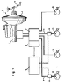
- the brake system according to the invention for motor vehicles shown in FIG. 1 essentially consists of a pressure sensor 1, a hydraulic unit 7, which is only indicated schematically and which, together with a first electronic controller (ABS / ASR controller 6), forms an anti-lock braking system, wheel brakes or wheel brake cylinders 12, 13 , 14,15, independently of the pressure transmitter 1 controllable or externally actuated Actuating units 8.9 and a second electronic controller (FSR controller 5) which interacts with the ABS / ASR controller 6 and whose control signals are used to control the operating units 8.9.
- Each of the vehicle wheels, not shown, is assigned a wheel sensor (not shown), whose control signal corresponding to the wheel speed is fed to the ABS / ASR controller 6.
- the assignment of the wheel brake cylinders 12 to 15 is preferably such that the wheel brake cylinders 12, 13 are assigned to a vehicle axle, possibly the driven front axle, and the wheel brake cylinders 14, 15 are assigned to the other, possibly the non-driven rear axle of the motor vehicle.
- the actuating units 8, 9 are inserted into hydraulic lines 10 and 11 leading to the wheel brake cylinders 12, 13 in such a way that they enable them to be shut off.
- the pressure transmitter 1 in turn consists of a pneumatic brake booster that can be actuated by means of an actuation or brake pedal 4, preferably a vacuum brake booster 3, which is followed by a double-circuit master brake cylinder, preferably a tandem master cylinder 2, which is connected to the hydraulic unit 7.
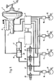
- the actuating units 8, 9 each consist of a hydraulic cylinder-piston arrangement 21, which is operatively connected upstream of an actuator 20 and which enables its external actuation.
- the actuating unit shown in FIG. 2 has a housing 32 which is provided with a first (input) connection 33 and a second (output) connection 35. Inside the housing 32 is a Hydraulic piston 22 is arranged axially displaceable, which is designed as an annular piston sealed on the outlet port 35 and has a pressure chamber 23 in its interior.
- the pressure chamber 23 is connected to the inlet connection 33 via a bore 26 provided in the end face of the piston 22 facing the inlet connection 33, the bore 26 being closable by means of a central valve 27.
- the central valve 27 consists of a preferably annular sealing seat 28 formed on the piston 22 and a valve body 29 cooperating with it and resiliently biased in the closing direction, which is held in the rest position of the piston 22 by axial contact with a stop 30 fixed to the housing at a distance from the sealing seat 28 , so that there is a hydraulic connection between the input (33) and output connection 35.
- the piston 22 delimits an annular space 34 in the housing, which is connected to the input port 33 or the end face of the piston 22 facing the input port 33 by means of a bore 36 formed in the piston 22, so that pressure actuation between the annular space 34 when actuated quickly and the input port 33 can take place.
- the abovementioned stop 30 is formed by the region of the housing 32 which is axially opposite the valve body 29.
- the actuator 20 of the actuation units shown in FIGS. 2 to 4 is arranged coaxially to the piston-cylinder arrangement 21 and consists of an electromagnet 24, the armature of which is formed by the piston 22.
- the electromagnet 24 can be designed as a lifting magnet, wherein in the housing 32 a sensor that detects the magnetic flux of the electromagnet 24, for example a Hall sensor 31, the piston 22 axially is arranged opposite.
- the output signals of the Hall sensor 31 are fed to the FSR controller 5, which regulates the force of the electromagnet 24 independently of the stroke.
- Another possibility is to regulate the force effect of the electromagnet 24 as a function of output signals from a differential pressure sensor 57, 58 (FIG. 8), which detects the pressure difference between the inlet and outlet pressures of the actuating unit 8, 9.
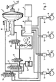
- the arrangement of the actuator 20 of the actuation unit shown in FIG. 3 corresponds identically to the embodiment described in connection with FIG. 2.
- the piston 22 is designed in the variant shown in FIG. 3 as a stepped piston, the step 37 of larger diameter is guided in a sealed manner on the cylindrical outlet connection 35, while the step 38 of smaller diameter is guided in a sealed manner in the housing 32 and is arranged axially opposite the inlet connection 33 so that it can be acted upon by the hydraulic pressure generated in the brake pressure sensor 1.
- the stage 37 of larger diameter delimits a pneumatic annular space 39 in the housing 32, which is connected by means of a bore 65 running parallel to its axis in the piston 22 to the end face of the stage 37 facing the input port 33, so that when the actuating unit is actuated a pneumatic one Pressure equalization can take place between the annular space 39 and the pneumatic space delimited by the end face facing the inlet connection 33.
- a filter element 62 is connected upstream of the stage 38 of smaller diameter, against which the valve body 29 rests axially in the rest position and which thus serves as the abovementioned fixed stop 30.
- the valve body 29 of the central valve 27 is finally formed by an axial extension of the armature 63 of the electromagnet 24, which is biased by means of a compression spring 64 against the closing direction of the central valve 27.
- the inlet connection 33 is formed perpendicular to the longitudinal axis of the cylinder-piston arrangement 21, while the outlet connection 35 is arranged coaxially to the piston 22, which is positioned in the rest position by resting on an annular surface 66 formed in the housing 32.
- hydraulically actuatable cylinder-piston arrangements 16, 17, 18, 19 are used, which are connected upstream of the individual wheel brake cylinders 12, 13, 14, 15 and can be controlled by a common hydraulic auxiliary pressure source.
- the auxiliary pressure source consists of an electric drive unit 41, for example an electromotive spindle-and-nut drive, which is effectively connected to an auxiliary cylinder 40.
- the individual cylinder-piston arrangements 16 to 19 are on the Auxiliary cylinder 40 connected by isolating valves 46,47,48,49, which are preferably designed as electromagnetically actuated, normally open (SO) or normally closed (SG) 2/2-way valves. Both the isolation valves 46, 47, 48, 49 and the drive unit 41 are controlled with control signals from the FSR controller 5.
- FIG. 6 shows one of the previously mentioned, hydraulically actuable cylinder-piston arrangements 16 to 19 in axial section.
- the arrangement shown has a stepped piston 25, which is sealed and displaceably guided in a housing 67, the step 70 of smaller diameter can be acted upon by the pressure generated in the pressure sensor 1, while the step 71 of larger diameter or the end face thereof by means of a third hydraulic connection 72 of the Auxiliary pressure source generated external pressure is supplied.
- the hydraulic auxiliary pressure source consists of a high-pressure accumulator 42, which is connected via a charging valve 43 to a pump 44 which can be driven by an electric motor 68 and which, on the other hand, is connected to the pressure transmitter 1 with the interposition of a switchover or pressure-limiting valve 45 or the tandem master cylinder 2 is connected.
- the pump 44 On its suction side, the pump 44 is connected to the hydraulic unit 7 of the anti-lock braking system, which is only shown schematically.
- the charging valve 43 which can be controlled by control signals from the FSR controller 5, is electromagnetically actuated, preferably without current Closed 2/2-way valve formed, while the changeover or pressure relief valve 45, which is used in particular in ASR control processes, is designed as an electromagnetically actuated 3/2-way valve, which separates the pump 44 from the tandem master cylinder 2 in its second switching position and creates a connection between the tandem master cylinder 2 and the hydraulic unit 7.
- the cylinder-piston arrangements 16, 17, 18, 19 mentioned in connection with FIGS. 5 and 6 are connected in pairs to the high-pressure accumulator 42 via pressure control valves 50, 51 which are designed as electromagnetically actuated 3/2-way valves.
- the cylinder-piston arrangements 16 to 19 are connected to a pressure medium reservoir 61 assigned to the tandem master cylinder 2, while they are separated from the high-pressure accumulator 42.
- the cylinder-piston arrangements 16, 17, 18, 19 are separated both from the pressure medium reservoir 61 and from the high pressure accumulator 42, while in a third switching position they are connected to the high pressure accumulator 42 and are separated from the pressure medium reservoir 61.
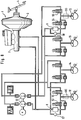
- Electromagnetically actuated actuation units 8, 9 are used, which are shown in FIGS. 2 to 4 and which are connected upstream of the wheel brake cylinders 12, 13 assigned to the driven front axle.
- inlet and outlet valves are provided, the inlet valves upstream of the wheel brake cylinders 12 and 13 of the driven front axle having the reference symbols 53 and 54 and the corresponding exhaust valves having the reference symbols 55 and 56 are provided.
- the actuating units 8, 9 mentioned are connected upstream of the inlet valves 53, 54 at the outlet of the pressure transmitter 1 or a return pump 52.
- the actuator (not shown) of the actuating unit 8, 9 is preferably formed by a lifting magnet, the force effect of which is regulated independently of the stroke in dependence on control signals from the actuating units 8, 9 connected in parallel differential pressure sensors 57, 58, which determine the pressure difference between the pressure transmitter 1 and the Return pump 52 generated input pressure and the output pressure of the actuating unit 8.9.
- FIG. 8 Another possibility of arranging the actuation units between the inlet valve 53, 54 and the wheel brake cylinder 12, 13 is shown in dashed lines in FIG. 8.
- the inlet and outlet valves 53, 54, 55, 56 belonging to the hydraulic unit mentioned above, the inlet and outlet valves assigned to the other vehicle axle, and the Return pump 52 are housed in a valve block in newer wheel slip control systems. It is therefore advisable to integrate the actuation units 8, 9 in the valve block.
- both a pressure build-up and a pressure reduction can be carried out in the wheel brake cylinders 12, 13 by actuating the pressure sensor 1 via the open connection (bore 26 Fig. 2 to Fig. 4, Fig. 6) and the open inlet valves 53, 54 (Fig . 8) take place so that there is no difference to previous brake systems.
- the externally controllable external force acts electrically (FIGS. 1, 2 to 4, 8) or hydraulically (FIGS. 5, 6, 7) on the pistons 22 and 25 of the cylinder-piston arrangement and moves it in the actuating direction the wheel brake cylinder 12, 13 or 12 to 15.
- the central valve 27 is closed and the force acting on the piston 22 or 25 generates a corresponding pressure in the wheel brake.
- electromagnetic actuators which are designed as lifting magnets, it is important that the external force must be applied independently of the stroke, since otherwise the proportion of external braking changes when the driver brakes. This can e.g. B. can be achieved with proportional magnets or switching magnets with regulated flux density.
- the required lifting work can be limited in that only one wheel is braked at a time and the maximum external actuating force can be limited to a value below the blocking pressure value.
- the external force acts as a hydraulically generated pressure force on the ring surface of the step 71 of larger diameter, which is separated by a seal from the end face of step 70 of smaller diameter.
- the piston 25 can also be designed as a synchronous piston, the transmission ratio between the tandem master cylinder 2 and the wheel brake cylinders 12 to 15 being retained. In the latter solution, a reduction in the actuating force applied by the driver on the wheel opposite the externally braked wheel is also conceivable.
- the pressure generated by the external actuation in the pressure chamber 23 shut off by the central valve 27 is increased directly by the brake pressure generated by the driver on the corresponding piston surface.
- the piston 22, 25 moves by the amount necessary for the pressure increase in the direction of the wheel brake cylinder 12 to 15.
- the volume withdrawal from the tandem master cylinder 2 thus corresponds to the usual increase in deceleration.
- the pressure difference across the pistons 22, 25 is maintained and corresponds to the external braking force.
- the check valve 27 remains closed.
- FSR braking connects to normal braking initiated by the driver, through which the wheel brake cylinders 12 to 15 have been primed via the open hydraulic connection (bore 26), the force effect of the external braking leads to the closing of the central valve 27 and to an increase in the wheel brake pressure. If the driver pressure is now reduced, the piston 22, 25 moves counter to the actuation direction of the wheel brake cylinders and the pressure prevailing therein is also reduced. If the amount of brake release is greater than the amount of external braking, the central valve 27 "sniffs" in its closed position and the volume is discharged from the wheel brake cylinders back to the tandem master cylinder 2.
- the ASR function is represented with the same measures as the FSR function.
- the overlay is thus electronic and is not a problem hydraulically.
- a two-channel system may be recommended, in which the actuator can act hydraulically on a right or left wheel brake depending on the valve position. This means that only the lifting work of a wheel brake can be achieved.
- the valves can be designed as two SO valves or a 3/2-way valve. If there are no special requirements for external power distribution at the front / rear, the two wheel brakes on the driver or passenger side can be operated centrally with a correspondingly reinforced actuator. If the third-party brake is completely independent of the normal brake, the third-party brake distribution can be done page by page.
Landscapes
- Engineering & Computer Science (AREA)
- Transportation (AREA)
- Mechanical Engineering (AREA)
- Physics & Mathematics (AREA)
- Fluid Mechanics (AREA)
- Regulating Braking Force (AREA)
Abstract
Description
Die Erfindung betrifft eine Bremsanlage für Kraftfahrzeuge mit einem pedalbetätigbaren Druckgeber, an dem Radbremszylinder von den einzelnen Rädern zugeordneten Radbremsen angeschlossen sind, mit mindestens zwei unabhängig vom Druckgeber ansteuerbaren Betätigungseinheiten, die in den hydraulischen Verbindungen zwischen Druckgeber und Radbremszylindern angeordnet sind, ein Absperren der hydraulischen Verbindungen ermöglichen und durch je eine Zylinder-Kolben-Anordnung und einen Aktuator gebildet sind, sowie mit einem elektronischen Regler, dessen Steuersignale der Ansteuerung der Betätigungseinheiten dienen, wobei bei gleichzeitiger Betätigung des Druckgebers und mindestens einer Betätigungseinheit am Kolben der Zylinder-Kolben-Anordnung eine Addition der aus dem Druckaufbau im Druckgeber resultierenden Kraft und der vom Aktuator aufgebrachten Fremdbetätigungskraft erfolgt.The invention relates to a brake system for motor vehicles with a pedal-operated pressure sensor, to which wheel brake cylinders of the individual wheels assigned to the wheel brakes are connected, with at least two actuation units which can be controlled independently of the pressure sensor and which are arranged in the hydraulic connections between pressure sensor and wheel brake cylinders, to shut off the hydraulic connections enable and are each formed by a cylinder-piston arrangement and an actuator, as well as with an electronic controller, the control signals of which are used to control the actuation units, with an addition at the same time actuation of the pressure transmitter and at least one actuation unit on the piston of the cylinder-piston arrangement the force resulting from the pressure build-up in the pressure transmitter and the external actuating force applied by the actuator.
Eine derartige Bremsanlage ist z. B. aus der europäischen Patentanmeldung EP 0 395 262 A2 bekannt. Bei der vorbekannten Bremsanlage ist die Betätigungseinheit durch einen hydraulischen Zylinder gebildet, dessen Kolben eine Verzahnung aufweist. Mit der Verzahnung wirkt ein Ritzel zusammen, das von einem Elektromotor angetrieben wird und dessen Drehbewegung in eine translatorische Bewegung des Kolbens umgewandelt wird. Weniger vorteilhaft ist bei der vorbekannten Bremsanlage der ungünstige Wirkungsgrad des Aktuators anzusehen, der auf die komplizierte Art der Umwandlung der dem Elektromotor zuzuführenden elektrischen Energie in die Verschiebebewegung des hydraulischen Kolbens zurückzuführen ist. Außerdem können aufgrund der Anordnung des Elektromotors senkrecht zur Längsachse des Zylinders sowie des verhältnismäßig hohen Gewichts erhebliche Probleme bei der Montage bzw. dem Einbau der bekannten Betätigungseinheit entstehen.Such a brake system is such. B. is known from European patent application EP 0 395 262 A2. In the known brake system, the actuation unit is formed by a hydraulic cylinder, the piston of which has teeth. A toothing cooperates with the toothing, which is driven by an electric motor and whose rotational movement is converted into a translatory movement of the piston. Is less advantageous with the previously known Brake system to see the unfavorable efficiency of the actuator, which is due to the complicated nature of the conversion of the electrical energy to be supplied to the electric motor into the displacement movement of the hydraulic piston. In addition, due to the arrangement of the electric motor perpendicular to the longitudinal axis of the cylinder and the relatively high weight, considerable problems can arise in the assembly or installation of the known actuating unit.
Es ist daher Aufgabe der vorliegenden Erfindung, eine Bremsanlage der eingangs genannten Gattung vorzuschlagen, bei der eine Erhöhung des Wirkungsgrades des Aktuators erreichbar ist. Außerdem sollen die Betätigungseinheiten kleine Abmessungen sowie ein niedriges Gewicht aufweisen.It is therefore an object of the present invention to propose a brake system of the type mentioned in the introduction in which an increase in the efficiency of the actuator can be achieved. In addition, the actuation units should have small dimensions and a low weight.
Eine erste Lösung der der Erfindung zugrundeliegenden Aufgabe besteht darin, daß der Aktuator durch einen Elektromagneten gebildet ist, dessen Anker den Kolben der Zylinder-Kolben-Anordnung bildet.A first solution to the problem on which the invention is based is that the actuator is formed by an electromagnet, the armature of which forms the piston of the cylinder-piston arrangement.
Eine optimale Ausnutzung der Hubarbeit des verwendeten Elektromagneten wird bei einer weiteren vorteilhaften Ausgestaltung der Erfindung dadurch erreicht, daß der Elektromagnet durch einen Hubmagneten gebildet ist, dessen Kraftwirkung hubunabhängig in Abhängigkeit von Ausgangssignalen eines Magnetflußsensors geregelt wird. Alternativ kann die Kraftwirkung des Hubmagneten in Abhängigkeit von Ausgangssignalen eines Differenzdrucksensors geregelt werden, der die Druckdifferenz zwischen dem vom Druckgeber aufgebrachten Druck und dem Ausgangsdruck der Zylinder-Kolben-Anordnung erfaßt.Optimal utilization of the lifting work of the electromagnet used is achieved in a further advantageous embodiment of the invention in that the electromagnet is formed by a lifting magnet, the force effect of which is regulated independently of the stroke as a function of output signals from a magnetic flux sensor. Alternatively, the force effect of the solenoid can be regulated as a function of output signals from a differential pressure sensor, which detects the pressure difference between the pressure applied by the pressure transmitter and the output pressure of the cylinder-piston arrangement.
Eine kompakte, kostengünstig herstellbare Ausführung des Erfindungsgegenstandes sieht vor, daß die Zylinder-Kolben-Anordnung und der Aktuator in einem Gehäuse angeordnet sind.A compact, inexpensive to produce embodiment of the subject matter of the invention provides that the cylinder-piston arrangement and the actuator are arranged in one housing.
Bei einer druckdichten Ausführung des Gehäuses ist es sinnvoll, wenn der Kolben als ein auf einem zylindrischen Anschluß abgedichtet geführter Hohlkolben ausgebildet ist und im Gehäuse einen hydraulischen Ringraum begrenzt, der mit dem hydraulischen Druck des Druckgebers beaufschlagbar ist.In the case of a pressure-tight design of the housing, it makes sense if the piston is designed as a hollow piston guided in a sealed manner on a cylindrical connection and delimits a hydraulic annular space in the housing which can be acted upon by the hydraulic pressure of the pressure transmitter.
Bei nichtdruckdichten Ausführungen des Gehäuses ist der Kolben als ein auf einem zylindrischen Anschluß abgedichtet geführter, gestufter Hohlkolben ausgebildet und begrenzt im Gehäuse einen pneumatischen Ringraum, der mit der dem Ringraum abgewandten Stirnfläche der Stufe größeren Durchmessers in Verbindung steht, wobei die Stufe kleineren Durchmessers im Gehäuse abgedichtet geführt ist und mit dem hydraulischen Druck des Druckgebers beaufschlagbar ist.In the case of non-pressure-tight versions of the housing, the piston is designed as a stepped hollow piston, which is sealed on a cylindrical connection, and delimits a pneumatic annular space in the housing, which is connected to the end face of the larger diameter step facing away from the annular space, the smaller diameter step in the housing is guided sealed and can be acted upon by the hydraulic pressure of the pressure transmitter.
Der Stufe kleineren Durchmessers kann ein Filterelement vorgeschaltet sein, das gleichzeitig als Anschlag für den Ventilkörper eines die hydraulische Verbindung zwischen Druckgeber und Radbremsen absperrenden Zentralventils dient.The smaller diameter stage can be preceded by a filter element, which at the same time serves as a stop for the valve body of a central valve which shuts off the hydraulic connection between pressure transmitter and wheel brakes.
Eine zweite Lösung der der Erfindung zugrundeliegenden Aufgabe, bei der der Aktuator der Zylinder-Kolben-Anordnung durch eine hydraulische Hilfsdruckquelle gebildet ist, besteht darin, daß die Hilfsdruckquelle durch durch einen Hochdruckspeicher gebildet ist, der vorzugsweise über ein Ladeventil an eine hydraulische Pumpe anschließbar ist, die andererseits über ein Umschalt- bzw. Druckbegrenzungsventil mit dem Druckgeber verbindbar ist. Als hydraulische Pumpe kann dabei eine der im Fahrzeug bereits vorhandenen Pumpen, beispielsweise die ABS- oder die Servolenkungspumpe verwendet werden.A second solution to the problem underlying the invention, in which the actuator of the cylinder-piston arrangement is formed by a hydraulic auxiliary pressure source, is that the auxiliary pressure source is formed by a high-pressure accumulator, which can preferably be connected to a hydraulic pump via a charging valve which, on the other hand, can be connected to the pressure transmitter via a changeover or pressure limiting valve. One of the pumps already present in the vehicle, for example the ABS or the power steering pump, can be used as the hydraulic pump.
Dabei können sämtliche Zylinder-Kolben-Anordnungen über Trennventile an einen zentral wirkenden Aktuator angeschlossen sein. Bei einer Ausführung, bei der die Trennventile als elektromagnetisch betätigbare, stromlos offene bzw. stromlos geschlossene 2/2-Wegeventile ausgebildet sind, können mit Vorteil kostengünstige ABS-Ventile Verwendung finden.All cylinder-piston arrangements can be connected to a centrally acting actuator via isolating valves. In an embodiment in which the isolating valves are designed as electromagnetically actuated, normally open or normally closed 2/2-way valves, inexpensive ABS valves can advantageously be used.
Eine weitere vorteilhafte Ausführung zeichnet sich dadurch aus, daß sämtliche Zylinder-Kolben-Anordnungen an den Hochdruckspeicher über Druckregelventile anschließbar sind. Durch diese Maßnahme wird erreicht, daß auch bei Änderungen des vom Fahrer im Druckgeber erzeugten Druckes ein konstant bleibender Fremddruck zur Verfügung gestellt wird.A further advantageous embodiment is characterized in that all cylinder-piston arrangements can be connected to the high-pressure accumulator via pressure control valves. This measure ensures that a constant external pressure is made available even when the pressure generated by the driver in the pressure transmitter changes.
Die Druckregelventile können dabei als elektromagnetisch betätigbare 3/3-Wegeventile ausgebildet sein, die in einer ersten Schaltstellung (Grundstellung) eine Verbindung der Zylinder-Kolben-Anordnungen mit einem drucklosen Druckmittelvorratsbehälter bei gleichzeitiger Trennung des Hochdruckspeichers ermöglichen, in einer zweiten Schaltstellung die Zylinder-Kolben-Anordnungen sowohl vom Hochdruckspeicher als auch vom Druckmittelvorratsbehälter trennen und in einer dritten Schaltstellung eine Verbindung der Zylinder-Kolben-Anordnungen mit dem Hochdruckspeicher bei gleichzeitiger Trennung des Druckmittelvorratsbehälters realisieren.The pressure control valves can be designed as electromagnetically operated 3/3-way valves, which in a first switching position (basic position) enable the cylinder-piston arrangements to be connected to a pressure-free pressure medium reservoir with simultaneous separation of the high-pressure accumulator, and the cylinder-piston in a second switching position Disconnect arrangements both from the high-pressure accumulator and from the pressure medium storage container and, in a third switching position, implement a connection of the cylinder-piston arrangements to the high-pressure accumulator with simultaneous separation of the pressure medium storage container.
Eine weitere vorteilhafte Ausgestaltung der Erfindung besteht darin, daß sie ein nach dem Rückförderprinzip arbeitendes hydraulisches Radschlupfregelsystem aufweist, wobei die Betätigungseinheiten vor dem jeweils einem Radbremszyllnder zugeordneten Einlaßventil am Ausgang der Rückförderpumpe angeordnet sind.
Durch die erwähnten Maßnahmen wird gewährleistet, daß in einem ABS-Regelfall der Fremdbremsdruck automatisch mit geregelt wird.A further advantageous embodiment of the invention consists in that it has a hydraulic wheel slip control system that works on the return principle, the actuating units being arranged in front of the inlet valve assigned to a wheel brake cylinder at the outlet of the return pump.
The measures mentioned ensure that the external brake pressure is automatically controlled in an ABS control case.
Um bereits vorhandene blockiergeschützte Bremsanlagen zu Fahrstabilitätsregelungszwecken verwenden zu können, sieht eine andere Weiterbildung des Erfindungsgegenstandes vor, daß die Betätigungseinheiten zwischen dem jeweils einem Radbremszylinder zugeordneten Einlaßventil und dem zugehörigen Radbremszylinder angeordnet sind.In order to be able to use existing anti-lock brake systems for driving stability control purposes, another development of the subject matter of the invention provides that the actuating units are arranged between the inlet valve assigned to a wheel brake cylinder and the associated wheel brake cylinder.
Um ein Blockieren durch Erzeugen des Fremddruckes zu verhindern, ist es dabei erforderlich, daß der die Betätigungseinheiten ansteuernde Regler (FSR-Regler) von Ausgangssignalen des ABS/ASR-Reglers beeinflußbar ist.In order to prevent blocking by generating the external pressure, it is necessary for the controller (FSR controller) which controls the actuating units to be able to be influenced by output signals from the ABS / ASR controller.
Außerdem ist es insbesondere bei ABS-Regelsystemen, die einen sowohl die ABS-Ventile als auch die Rückförderpumpe aufnehmenden Ventilblock aufweisen, sinnvoll, wenn die Betätigungseinheiten im Ventilblock integriert sind.In addition, it is particularly useful in ABS control systems that have a valve block that accommodates both the ABS valves and the return pump if the actuating units are integrated in the valve block.
Die Erfindung wird in der nachfolgenden Beschreibung an vier Ausführungsbeispielen im Zusammenhang mit der beiliegenden Zeichnung näher erläutert. In der Zeichnung zeigt:
- Fig. 1
- ein hydraulisches vereinfachtes Schaltbild einer ersten Ausführung der erfindungsgemäßen Bremsanlage;
- Fig. 2
- eine erste Ausführung von bei der Bremsanlage nach Fig. 1 verwendbaren Betätigungseinheiten;
- Fig. 3
- eine zweite Ausführung von bei der Bremsanlage nach Fig. 1 verwendbaren Betätigungseinheiten;
- Fig. 4
- eine dritte Ausführung von bei der Bremsanlage nach Fig. 1 verwendbaren Betätigungseinheiten;
- Fig. 5
- ein hydraulisches Schaltbild einer zweiten Ausführung der erfindungsgemäßen Bremsanlage;
- Fig. 6
- eine Ausführung von bei der Bremsanlage nach Fig. 5 verwendbaren Betätigungseinheiten;
- Fig. 7
- ein hydraulisches Schaltbild einer dritten Ausführung der erfindungsgemäßen Bremsanlage und
- Fig. 8
- ein hydraulisches Schaltbild einer vierten Ausführung der erfindungsgemäßen Bremsanlage.
- Fig. 1
- a hydraulic simplified circuit diagram of a first embodiment of the brake system according to the invention;
- Fig. 2
- a first embodiment of actuating units that can be used in the braking system according to FIG. 1;
- Fig. 3
- a second embodiment of actuating units that can be used in the braking system according to FIG. 1;
- Fig. 4
- a third embodiment of actuating units that can be used in the braking system according to FIG. 1;
- Fig. 5
- a hydraulic circuit diagram of a second embodiment of the brake system according to the invention;
- Fig. 6
- an embodiment of actuating units that can be used in the braking system according to FIG. 5;
- Fig. 7
- a hydraulic circuit diagram of a third embodiment of the brake system according to the invention and
- Fig. 8
- a hydraulic circuit diagram of a fourth embodiment of the brake system according to the invention.
Die in Fig. 1 gezeigte erfindungsgemäße Bremsanlage für Kraftfahrzeuge besteht im wesentlichen aus einem Druckgeber 1, einem lediglich schematisch angedeuteten Hydroaggregat 7, das zusammen mit einem ersten elektronischen Regler (ABS/ASR-Regler6) ein Antiblockiersystem bildet, Radbremsen bzw. Radbremszylindern 12,13,14,15, unabhängig vom Druckgeber 1 ansteuerbaren bzw. fremdbetätigbaren Betätigungseinheiten 8,9 sowie einem mit dem ABS/ASR-Regler 6 zusammenwirkenden zweiten elektronischen Regler (FSR-Regler 5), dessen Steuersignale der Ansteuerung der Betätigungseinheiten 8,9 dienen. Jedem der nicht gezeigten Fahrzeugräder ist je ein näher nicht bezeichneter Radsensor zugeordnet, dessen der Radgeschwindigkeit entsprechendes Steuersignal dem ABS/ASR-Regler 6 zugeführt wird. Die Zuordnung der Radbremszylinder 12 bis 15 ist dabei vorzugsweise derart getroffen, daß die Radbremszylinder 12,13 einer Fahrzeugachse, ggf. der angetriebenen Vorderachse und die Radbremszylinder 14,15 der anderen, ggf. der nicht angetriebenen Hinterachse des Kraftfahrzeuges zugeordnet sind. Die Betätigungseinheiten 8,9 sind dabei in zu den Radbremszylindern 12,13 führenden hydraulischen Leitungen 10 und 11 so eingefügt, daß sie deren Absperren ermöglichen. Der Druckgeber 1 besteht seinerseits aus einem mittels eines Betätigungs- bzw. Bremspedals 4 betätigbaren pneumatischen Bremskraftverstärker, vorzugsweise einem Unterdruckbremskraftverstärker 3, dem ein zweikreisiger Hauptbremszylinder, vorzugsweise ein Tandemhauptzylinder 2, nachgeschaltet ist, der mit dem Hydroaggregat 7 in Verbindung steht.The brake system according to the invention for motor vehicles shown in FIG. 1 essentially consists of a pressure sensor 1, a hydraulic unit 7, which is only indicated schematically and which, together with a first electronic controller (ABS / ASR controller 6), forms an anti-lock braking system, wheel brakes or
Wie insbesondere Fig. 2, 3 und 4 zeigen, bestehen die Betätigungseinheiten 8,9 aus je einer hydraulischen Zylinder-Kolben-Anordnung 21, der wirkungsmäßig je ein Aktuator 20 vorgeschaltet ist und der deren Fremdbetätigung ermöglicht. Die in Fig. 2 dargestellte Betätigungseinheit weist ein Gehäuse 32 auf, das mit einem ersten (Eingangs-) Anschluß 33 sowie einem zweiten (Ausgangs-) Anschluß 35 versehen ist. Im Inneren des Gehäuses 32 ist ein hydraulischer Kolben 22 axial verschiebbar angeordnet, der als Ringkolben ausgebildet auf dem Ausgangsanschluß 35 abgedichtet geführt ist und in seinem Inneren einen Druckraum 23 aufweist. Der Druckraum 23 steht über eine in der dem Eingangsanschluß 33 zugewandten Stirnfläche des Kolbens 22 vorgesehene Bohrung 26 mit dem Eingangsanschluß 33 in Verbindung, wobei die Bohrung 26 mittels eines Zentralventils 27 absperrbar ist. Das Zentralventil 27 besteht aus einem am Kolben 22 ausgebildeten, vorzugsweise ringförmigen Dichtsitz 28 sowie einem mit ihm zusammenwirkenden, federnd in Schließrichtung vorgespannten Ventilkörper 29, der in der Ruhestellung des Kolbens 22 durch axiale Anlage an einem gehäusefesten Anschlag 30 im Abstand vom Dichtsitz 28 gehalten wird, so daß eine hydraulische Verbindung zwischen Eingangs-(33) und Ausgangsanschluß 35 besteht. Außerdem begrenzt der Kolben 22 im Gehäuse einen Ringraum 34, der mittels einer im Kolben 22 ausgebildeten Bohrung 36 mit dem Eingangsanschluß 33 bzw. der dem Eingangsanschluß 33 zugewandten Stirnfläche des Kolbens 22 in Verbindung steht, so daß bei schneller Betätigung ein Druckausgleich zwischen dem Ringraum 34 und dem Eingangsanschluß 33 stattfinden kann. Der erwähnte Anschlag 30 wird dabei durch den dem Ventilkörper 29 axial gegenüberliegenden Bereich des Gehäuses 32 gebildet.As shown in FIGS. 2, 3 and 4 in particular, the
Der Aktuator 20 der in Fig. 2 bis 4 dargestellten Betätigungseinheiten ist koaxial zur Kolben-Zylinder-Anordnung 21 angeordnet und besteht aus einem Elektromagneten 24, dessen Anker durch den Kolben 22 gebildet wird. Der Elektromagnet 24 kann dabei als Hubmagnet ausgeführt sein, wobei im Gehäuse 32 ein den Magnetfluß des Elektromagneten 24 erfassender Sensor, beispielsweise ein Hallsensor 31, dem Kolben 22 axial gegenüberliegend angeordnet ist. Die Ausgangssignale des Hallsensors 31 werden dem FSR-Regler 5 zugeführt, der hubunabhängig die Kraftwirkung des Elektromagneten 24 regelt. Eine andere Möglichkeit besteht darin, die Kraftwirkung des Elektromagneten 24 in Abhängigkeit von Ausgangssignalen eines Differenzdrucksensors 57,58 (Fig. 8) zu regeln, der die Druckdifferenz zwischen dem Ein- und Ausgangsdruck der Betätigungseinheit 8,9 erfaßt.The
Die Anordnung des Aktuators 20 der in Fig. 3 dargestellten Betätigungseinheit entspricht identisch der im Zusammenhang mit Fig. 2 beschriebenen Ausführung. Der Kolben 22 ist bei der in Fig. 3 gezeigten Variante als ein Stufenkolben ausgeführt, dessen Stufe 37 größeren Durchmessers auf dem zylindrischen Ausgangsanschluß 35 abgedichtet geführt ist, während die Stufe 38 kleineren Durchmessers im Gehäuse 32 abgedichtet geführt und dem Eingangsanschluß 33 axial gegenüberliegend angeordnet ist, so daß sie mit dem im Bremsdruckgeber 1 erzeugten hydraulischen Druck beaufschlagbar ist. Die Stufe 37 größeren Druchmessers begrenzt im Gehäuse 32 einen pneumatischen Ringraum 39, der mittels einer im Kolben 22 parallel zu dessen Achse verlaufenden Bohrung 65 mit der dem Eingangsanschluß 33 zugewandten Stirnfläche der Stufe 37 in Verbindung steht, so daß bei der Ansteuerung der Betätigungseinheit ein pneumatischer Druckausgleich zwischen dem Ringraum 39 und dem durch die dem Eingangsanschluß 33 zugewandten Stirnseite begrenzten pneumatischen Raum stattfinden kann.The arrangement of the
Um ein Eindringen von Schmutzpartikeln in den Bereich des Zentralventils 27 wirksam zu verhindern, ist der Stufe 38 kleineren Durchmessers ein Filterelement 62 vorgeschaltet, an dem in der Ruhestellung der Ventilkörper 29 axial anliegt und der somit als der oben erwähnte gehäusefeste Anschlag 30 dient.In order to effectively prevent dirt particles from penetrating into the area of the
Bei der in Fig. 4 gezeigten elektrohydraulischen Betätigungseinheit ist der Ventilkörper 29 des Zentralventils 27 schließlich durch eine axiale Verlängerung des Ankers 63 des Elektromagneten 24 gebildet, der mittels einer Druckfeder 64 entgegen der Schließrichtung des Zentralventils 27 vorgespannt ist. Der Eingangsanschluß 33 ist bei der dargestellten Ausführung senkrecht zur Längsachse der Zylinder-Kolben-Anordnung 21 ausgebildet, während der Ausgangsanschluß 35 koaxial zum Kolben 22 angeordnet ist, der in Ruhestellung durch Anlage an einer im Gehäuse 32 ausgebildeten Ringfläche 66 positioniert ist.In the electro-hydraulic actuation unit shown in FIG. 4, the
Bei der in Fig. 5 dargestellten erfindungsgemäßen Bremsanlage finden hydraulisch betätigbare Zylinder-Kolben-Anordnungen 16,17,18,19 Verwendung, die den einzelnen Radbremszylindern 12,13,14,15 vorgeschaltet und von einer gemeinsamen hydraulischen Hilfsdruckquelle ansteuerbar sind. Die Hilfsdruckquelle besteht aus einer elektrischen Antriebseinheit 41, beispielsweise einem elektromotorisch betätigbaren Spindel-Mutter-Antrieb, dem wirkungsmäßig ein Hilfszylinder 40 nachgeschaltet ist. Die einzelnen Zylinder-Kolben-Anordnungen 16 bis 19 sind an den Hilfszylinder 40 mittels Trennventile 46,47,48,49 angeschlossen, die vorzugsweise als elektromagnetisch betätigbare, stromlos offene (SO) bzw. stromlos geschlossene (SG) 2/2-Wegeventile ausgeführt sind. Sowohl die Trennventile 46,47,48,49 als auch die Antriebseinheit 41 werden mit Steuersignalen des FSR-Regelers 5 angesteuert.In the brake system according to the invention shown in FIG. 5, hydraulically actuatable cylinder-
Fig. 6 zeigt eine der vorhin erwähnten, hydraulisch betätigbaren Zylinder-Kolben-Anordnungen 16 bis 19 im Axialschnitt. Die dargestellte Anordnung weist einen in einem Gehäuse 67 abgedichtet verschiebbar geführten Stufenkolben 25 auf, dessen Stufe 70 kleineren Durchmessers mit dem im Druckgeber 1 erzeugten Druck beaufschlagbar ist, während der Stufe 71 größeren Durchmessers bzw. deren Stirnfläche mittels eines dritten hydraulischen Anschlusses 72 der von der Hilfsdruckquelle erzeugte Fremddruck zugeführt wird.6 shows one of the previously mentioned, hydraulically actuable cylinder-
Bei der in Fig. 7 dargestellten erfindungsgemäßen Bremsanlage besteht die hydraulische Hilfsdruckquelle aus einem Hochdruckspeicher 42, der über ein Ladeventil 43 an eine mittels eines Elektromotors 68 antreibbare Pumpe 44 angeschlossen ist, die andererseits unter Zwischenschaltung eines Umschalt- bzw. Druckbegrenzungsventils 45 mit dem Druckgeber 1 bzw. dem Tandemhauptzylinder 2 in Verbindung steht. An ihrer Saugsseite ist die Pumpe 44 an das lediglich schematisch dargestellte Hydroaggregat 7 des Antiblockiersystems angeschlossen. Das durch Steuersignale des FSR-Reglers 5 ansteuerbare Ladeventil 43 ist dabei als elektromagnetisch betätigbares, vorzugsweise stromlos geschlossenes 2/2-Wegeventil ausgebildet, während das Umschalt- bzw. Druckbegrenzungsventil 45, das insbesondere bei ASR-Regelvorgängen Verwendung findet, als elektromagnetisch betätigbares 3/2-Wegeventil ausgeführt ist, das in seiner zweiten Schaltstellung die Pumpe 44 vom Tandemhauptzylinder 2 trennt und eine Verbindung zwischen dem Tandemhauptzylinder 2 und dem Hydroaggregat 7 herstellt. Die im Zusammenhang mit Fig. 5 und 6 erwähnten Zylinder-Kolben-Anordnungen 16,17,18,19 sind an den Hochdruckspeicher 42 paarweise über Druckregelventile 50,51 angeschlossen, die als elektromagnetisch betätigbare 3/2-Wegeventile ausgebildet sind. In einer ersten Schaltstellung bzw. dem stromlosen Zustand entsprechenden Grundstellung der Druckregelventile 50,51 stehen die Zylinder-Kolben-Anordnungen 16 bis 19 in Verbindung mit einem dem Tandemhauptzylinder 2 zugeordneten Druckmittelvorratsbehälter 61, während sie vom Hochdruckspeicher 42 getrennt sind. In einer zweiten Schaltstellung sind die Zylinder-Kolben-Anordnungen 16,17,18,19 sowohl vom Druckmittelvorratsbehälter 61 als auch vom Hochdruckspeicher 42 getrennt, während sie in einer dritten Schaltstellung mit dem Hochdruckspeicher 42 in Verbindung stehen und vom Druckmittelvorratsbehälter 61 getrennt sind.In the brake system according to the invention shown in FIG. 7, the hydraulic auxiliary pressure source consists of a high-
Fig. 8 zeigt schließlich eine stark vereinfachte Kombination der erfindungsgemäßen Bremsanlage mit einem nach dem Rückförderprinzip arbeitenden Antiblockier- bzw. Radschlupfregelsystem, wobei in der Darstellung der besseren Übersichtlichkeit halber beide Regler 5,6 weggelassen wurden. Bei der gezeigten Ausführung kommen elektromagnetisch betätigbare Betätigungseinheiten 8,9 zum Einsatz, die in Fig. 2 bis 4 gezeigt sind und die den der angetriebenen Vorderachse zugeordneten Radbremszylindern 12,13 vorgeschaltet sind. Um in einem Antiblockierregelfall eine Druckmodulation an den einzelnen Radbremszylindern 12 bis 15 zurückführen zu können, sind Ein- und Auslaßventile vorgesehen, wobei die den Radbremszylindern 12 und 13 der angetriebenen Vorderachse vorgeschalteten Einlaßventile mit den Bezugszeichen 53 und 54 und die entsprechenden Auslaßventile mit den Bezugszeichen 55 und 56 versehen sind. Die erwähnten Betätigungseinheiten 8,9 sind dabei vor den Einlaßventilen 53,54 am Ausgang des Druckgebers 1 bzw. einer Rückförderpumpe 52 geschaltet. Der nicht gezeigte Aktuator der Betätigungseinheit 8,9 ist vorzugsweise durch einen Hubmagneten gebildet, dessen Kraftwirkung hubunabhängig in Abhängigkeit von Steuersignalen von den Betätigungseinheiten 8,9 parallel geschalteten Differenzdrucksensoren 57,58 geregelt wird, die die Druckdifferenz zwischen dem durch den Druckgeber 1 bzw. die Rückförderpumpe 52 erzeugten Eingangsdruck und dem Ausgangsdruck der Betätigungseinheit 8,9 erfassen.8 finally shows a greatly simplified combination of the brake system according to the invention with an anti-lock or wheel slip control system working according to the return feed principle, both
Eine weitere Möglichkeit der Anordnung der Betätigungseinheiten zwischen dem Einlaßventil 53,54 und dem Radbremszylinder 12,13 ist in Fig. 8 gestrichelt dargestellt.Another possibility of arranging the actuation units between the
Die zum vorhin erwähnten Hydroaggregat gehörenden Ein- und Auslaßventile 53,54,55,56, die der anderen Fahrzeugachse zugeordneten Ein- und Auslaßventile sowie die Rückförderpumpe 52 sind bei neueren Radschlupfregelsystemen in einem Ventilblock untergebracht. Es ist daher sinnvoll, die Betätigungseinheiten 8,9 im Ventilblock zu integrieren.The inlet and
Bei einer Normalbremsung können in den Radbremszylindern 12,13 sowohl ein Druckauf- als auch ein Druckabbau durch Betätigung des Druckgebers 1 über die offene Verbindung (Bohrung 26 Fig. 2 bis Fig 4, Fig. 6) sowie die offenen Einlaßventile 53,54 (Fig. 8) erfolgen, so daß kein Unterschied zu bisherigen Bremssystemen auftritt.During normal braking, both a pressure build-up and a pressure reduction can be carried out in the
Bei einer Fahrstabilitäts-Regelbremsung wirkt die elektrisch (Fig. 1, 2 bis 4, 8) oder hydraulisch (Fig. 5, 6, 7) steuerbare Fremdkraft auf den Kolben 22 bzw. 25 der Zylinder-Kolben-Anordnung und bewegt ihn in Betätigungsrichtung der Radbremszylinder 12,13 bzw. 12 bis 15. Hierdurch wird das Zentralventil 27 geschlossen und die auf den Kolben 22 bzw. 25 wirkende Kraft erzeugt in der Radbremse einen entsprechenden Druck. Bei elektromagnetischen Aktuatoren, die als Hubmagneten ausgebildet sind, ist dabei wichtig, daß die Fremdkraft hubunabhängig aufgebracht werden muß, da sonst bei zusätzlicher Bremsaktivität des Fahrers der Fremdbremsanteil sich ändert. Dies kann z. B. mit Proportionalmagneten oder Schaltmagneten mit geregelter Flußdichte erreicht werden. Die erforderliche Hubarbeit ist dabei dadurch eingrenzbar, daß nur jeweils ein Rad gebremst wird und die maximale Fremdbetätigungskraft auf einen Wert unterhalb des Blockierdruckwertes beschränkt werden kann. Bei Verwendung eines Elektromotors mit Spindel-Mutter-Antrieb ist darauf zu achten, daß keine Selbsthemmung auftritt.In the case of driving stability control braking, the externally controllable external force acts electrically (FIGS. 1, 2 to 4, 8) or hydraulically (FIGS. 5, 6, 7) on the
Bei dem in Fig. 6 gezeigten Druck-/Druckadditionsmodul wirkt die Fremdkraft als hydraulisch erzeugte Druckkraft auf die Ringfläche der Stufe 71 größeren Durchmessers, die durch eine Dichtung von der Stirnfläche der Stufe 70 kleineren Druchmessers getrennt ist. Der Kolben 25 kann auch als Gleichlaufkolben ausgebildet sein, wobei das Übersetzungsverhältnis zwischen Tandemhauptzylinder 2 und Radbremszylindern 12 bis 15 erhalten bleibt, Bei der letztgenannten Lösung ist auch eine Reduzierung der vom Fahrer aufgebrachten Betätigungskraft an dem dem fremdgebremsten Rad gegenüberliegenden Rad denkbar.In the pressure / pressure addition module shown in FIG. 6, the external force acts as a hydraulically generated pressure force on the ring surface of the
Wird gleichzeitig mit einer FSR-Regelbremsung eine Fahrerbremsbetätigung eingeleitet, so wird im durch das Zentralventil 27 abgesperrten Druckraum 23 der durch die Fremdbetätigung erzeugte Druck unmittelbar um den auf die entsprechende Kolbenfläche wirkenden, vom Fahrer erzeugten Bremsdruck erhöht. Hierbei bewegt sich der Kolben 22, 25 um den für die Druckerhöhung notwendigen Betrag in Richtung Radbremszylinder 12 bis 15. Damit entspricht die Volumenentnahme aus dem Tandemhauptzylinder 2 der gewohnten Verzögerungserhöhung. Die Druckdifferenz am Kolben 22, 25 bleibt erhalten und entspricht der Fremdbremskraft. Das Rückschlagventil 27 bleibt geschlossen.If driver brake actuation is initiated simultaneously with FSR control braking, the pressure generated by the external actuation in the pressure chamber 23 shut off by the
Tritt ein kritischer Radschlupfzustand auf, so wird je nach Regelphilosophie und Erfordernis entweder erst nur das Antiblockiersystem für die hydraulische Bremse aktiviert und dann die Fremdkraft zurückgenommen oder beides gleichzeitig oder umgekehrt. Um eine gewohnte Rückwirkung auf den Fahrerfuß zu erhalten, wird die Aktivierung des Standard-ABS sinnvoll sein.If a critical wheel slip condition occurs, then depending on the control philosophy and requirements, either only the anti-lock braking system for the hydraulic brake is activated and then the external force is withdrawn or both simultaneously or vice versa. In order to get the usual feedback on the driver's foot, the activation of the standard ABS will make sense.
Das Lösen bei der Normalbremsung erfolgt unmittelbar. Die Fremdbremsung bleibt erhalten, solange sie aktiviert ist.The release during normal braking takes place immediately. External braking is retained as long as it is activated.
Erfolgt zuerst die Aktivierung der Fremdbremsung, so wird der vorgespannte Kolben 22,25 in seine Ausgangsposition zurückgeschoben, da das Rückschlagventil 27 sich öffnet.If the external braking is activated first, the
Schließt eine FSR-Bremsung an eine vom Fahrer eingeleitete Normalbremsung an, durch die die Radbremszylinder 12 bis 15 über die offene hydraulische Verbindung (Bohrung 26) vorgefüllt wurden, so führt die Kraftwirkung der Fremdbremsung zum Schließen des Zentralventils 27 und zur Erhöhung des Radbremsdruckes. Erfolgt nun eine Reduzierung des Fahrerdrucks, so bewegt sich der Kolben 22, 25 entgegen der Betätigungsrichtung der Radbremszylinder und der darin herrschende Druck wird ebenso reduziert. Ist das Lösen der Bremse betragsmäßig größer als der Fremdbremsanteil, so "schnüffelt" das Zentralventil 27 in seiner Schließposition und das Volumen wird aus den Radbremszylindern wieder zum Tandemhauptzylinder 2 abgeführt.If FSR braking connects to normal braking initiated by the driver, through which the
Die ASR-Funktion wird mit den gleichen Maßnahmen dargestellt, wie die FSR-Funktion. Die Überlagerung erfolgt somit elektronisch und ist hydraulisch unproblematisch.The ASR function is represented with the same measures as the FSR function. The overlay is thus electronic and is not a problem hydraulically.
Um den Aufwand beim elektrischen Aktuator gering zu halten, empfiehlt sich möglicherweise eine Zwei-Kanal-Anlage, bei der der Aktuator wahlweise je nach Ventilstellung hydraulisch auf eine rechte oder linke Radbremse wirken kann. Damit ist nur die Hubarbeit einer Radbremse zu leisten. Die Ventile können als zwei SO-Ventile oder ein 3/2-Wegeventil ausgebildet sein. Sollten keine besoderen Anforderungen an die Fremdkraftverteilung vorn/hinten gestellt werden, so können mit einem entsprechend verstärkten Aktuator die beiden Radbremsen auf der Fahrer- oder auf der Beifahrerseite zentral betätigt werden. Bei vollkommen unabhängig von der Normalbremse wirkenden Fremdbremse kann die Fremdbremsaufteilung seitenweise erfolgen.In order to keep the expense of the electrical actuator low, a two-channel system may be recommended, in which the actuator can act hydraulically on a right or left wheel brake depending on the valve position. This means that only the lifting work of a wheel brake can be achieved. The valves can be designed as two SO valves or a 3/2-way valve. If there are no special requirements for external power distribution at the front / rear, the two wheel brakes on the driver or passenger side can be operated centrally with a correspondingly reinforced actuator. If the third-party brake is completely independent of the normal brake, the third-party brake distribution can be done page by page.
- 11
- DruckgeberThruster
- 22nd
- HauptbremszylinderMaster brake cylinder
- 33rd
- UnterdruckbremskraftverstärkerVacuum brake booster
- 44th
- BetätigungspedalOperating pedal
- 55
- FSR-ReglerFSR controller
- 66
- ABS/ASR-ReglerABS / ASR controller
- 77
- HydroaggregatHydraulic power pack
- 88th
- BetätigungseinheitActuator
- 99
- BetätigungseinheitActuator
- 1010th
- Leitungmanagement
- 1111
- Leitungmanagement
- 1212th
- RadbremszylinderWheel brake cylinder
- 1313
- RadbremszylinderWheel brake cylinder
- 1414
- RadbremszylinderWheel brake cylinder
- 1515
- RadbremszylinderWheel brake cylinder
- 1616
- Zylinder-Kolben-AnordnungCylinder-piston arrangement
- 1717th
- Zylinder-Kolben-AnordnungCylinder-piston arrangement
- 1818th
- Zylinder-Kolben-AnordnungCylinder-piston arrangement
- 1919th
- Zylinder-Kolben-AnordnungCylinder-piston arrangement
- 2020th
- AktuatorActuator
- 2121
- Zylinder-Kolben-AnordnungCylinder-piston arrangement
- 2222
- Kolbenpiston
- 2323
- DruckraumPressure room
- 2424th
- ElektromagnetElectromagnet
- 2525th
- Kolbenpiston
- 2626
- Bohrungdrilling
- 2727
- ZentralventilCentral valve
- 2828
- DichtsitzSealing seat
- 2929
- VentilkörperValve body
- 3030th
- Anschlagattack
- 3131
- HallsensorHall sensor
- 3232
- Gehäusecasing
- 3333
- Anschluß (Eingangsanschluß)Connection (input connection)
- 3434
- RingraumAnnulus
- 3535
- AusgangsanschlußOutput connector
- 3636
- Bohrungdrilling
- 3737
- Stufestep
- 3838
- Stufestep
- 3939
- RingraumAnnulus
- 4040
- HilfszylinderAuxiliary cylinder
- 4141
- AntriebseinheitDrive unit
- 4242
- HochdruckspeicherHigh pressure accumulator
- 4343
- LadeventilCharging valve
- 4444
- Pumpepump
- 4545
- DruckbgrenzungsventilPressure relief valve
- 4646
- TrennventilIsolation valve
- 4747
- TrennventilIsolation valve
- 4848
- TrennventilIsolation valve
- 4949
- TrennventilIsolation valve
- 5050
- Trennventil, DruckregelventilIsolation valve, pressure control valve
- 5151
- Trennventil, DruckregelventilIsolation valve, pressure control valve
- 5252
- RückförderpumpeReturn pump
- 5353
- EinlaßventilInlet valve
- 5454
- EinlaßventilInlet valve
- 5555
- AuslaßventilExhaust valve
- 5656
- AuslaßventilExhaust valve
- 5757
- DifferenzdrucksensorDifferential pressure sensor
- 5858
- DifferenzdrucksensorDifferential pressure sensor
- 6060
- --
- 6161
- DruckmittelvorratsbehälterPressure fluid reservoir
- 6262
- FilterelementFilter element
- 6363
- Ankeranchor
- 6464
- DruckfederCompression spring
- 6565
- Bohrungdrilling
- 6666
- RingflächeRing surface
- 6767
- Gehäusecasing
- 6868
- ElektromotorElectric motor
- 6969
- 7070
- Stufestep
- 7171
- Stufestep
- 7272
- AnschlußConnection
Claims (17)
- Brake system for automotive vehicles including a pedal-operable pressure generator (1) connected to wheel brake cylinders (12, 13, 14, 15) of wheel brakes associated with the individual wheels, at least two actuator units (8, 9) actuatable independently of the pressure generator (1) and arranged in hydraulic connections (10, 11) between pressure generator (1) and wheel brake cylinders (12, 13) to permit shutting off the hydraulic connections (10, 11), each of the actuator units including one cylinder-and-piston assembly (21) and one actuator (20), and an electronic controller (DSC controller) (6) whose control signals serve to actuate the actuator units (8, 9), wherein, on simultaneous actuation of the pressure generator (1) and at least one actuator unit (8, 9), the force resulting from the pressure build-up in the pressure generator (1) is added to the external actuating force generated by the actuator (20) and applied to the piston (22, 25) of the cylinder-and-piston assembly (21, 16, 17, 18, 19),
characterized in that the actuator (20) is an electromagnet (24) whose armature is the piston (22). - Brake system as claimed in claim 1,
characterized in that the electromagnet (24) is a stroke magnet whose action of force is controlled irrespective of stroke in response to output signals of a magnetic flux sensor (Hall sensor 31). - Brake system as claimed in claim 1,
characterized in that the electromagnet (24) is a stroke magnet whose action of force is controlled irrespective of stroke in response to output signals of a differential pressure sensor (57, 58) sensing the pressure differential between the inlet pressure and the outlet pressure of the actuator unit (8, 9). - Brake system as claimed in claim 1,
characterized in that the cylinder-and-piston assembly (21) and the actuator (20 or 24) are accommodated in one housing (32). - Brake system as claimed in claim 4,
characterized in that the piston (22) is a hollow piston which is sealedly guided on a cylindrical outlet port (35) and defines in the housing (32) a hydraulic annular chamber (34) to which the hydraulic pressure of the pressure generator (1) can be applied. - Brake system as claimed in claim 4,
characterized in that the piston (22) is a stepped hollow piston which is sealedly guided on a cylindrical outlet port (35) and defines in the housing (32) a pneumatic annular chamber (39) which is connected to the end surface of the large-diameter step (37) remote from the annular chamber, and the small-diameter step (38) is sealed in the housing (32) and can be acted upon by the hydraulic pressure of the pressure generator (1). - Brake system as claimed in claim 6,
characterized in that a filter element (62) precedes the small-diameter step (38), serving additionally as a stop (30) for a valve member (29) of the central valve (27) which shuts off the hydraulic connection between pressure generator (1) and wheel brakes (12, 13, 14, 15). - Brake system for automotive vehicles including a pedal-operable pressure generator (1) connected to wheel brake cylinders (12, 13, 14, 15) of wheel brakes associated with the individual wheels, at least two actuator units (8, 9) actuatable independently of the pressure generator (1) and arranged in hydraulic connections (10, 11) between pressure generator (1) and wheel brake cylinders (12, 13) to permit shutting off the hydraulic connections (10, 11), each of the actuator units including one cylinder-and-piston assembly (21) and one actuator (20), and an electronic controller (DSC controller) (6) whose control signals serve to actuate the actuator units (8, 9), wherein, on simultaneous actuation of the pressure generator (1) and at least one actuator unit (8, 9), the force resulting from the pressure build-up in the pressure generator (1) is added to the external actuating force generated by the actuator (20) and applied to the piston (25) of the cylinder-and-piston assembly (16, 17, 18, 19), and wherein the actuator (20) is a hydraulic auxiliary pressure source,
characterized in that the auxiliary pressure source is a high-pressure accumulator (42). - Brake system as claimed in claim 8,
characterized in that the high-pressure accumulator (42) is connectable by way of a charging valve (43) to a hydraulic pump (44) which, in turn, is connectable to the pressure generator (1) by way of a change-over or pressure-limiting valve (45). - Brake system as claimed in claim 8 or 9,
characterized in that all cylinder-and-piston assemblies (16, 17, 18, 19) are connected to a central actuator (20) by way of separating valves (46, 47, 48, 49, 50, 51). - Brake system as claimed in claim 10,
characterized in that the separating valves (46, 47, 48, 49) are electromagnetically operable, normally open or normally closed two-way/two-position directional control valves. - Brake system as claimed in claim 8 or 9,
characterized in that all cylinder-and-piston assemblies (16, 17, 18, 19) are connectable to the high-pressure accumulator (42) by way of pressure control valves (50, 51). - Brake system as claimed in claim 12,
characterized in that the pressure control valves (50, 51) are electromagnetically operable three-way/three-position directional control valves which, in a first switch position (initial position), permit a connection between the cylinder-and-piston assemblies (16, 17, 18, 19) and an unpressurized pressure fluid supply reservoir (61), with a simultaneous disconnection of the high-pressure accumulator (42), in a second switch position, separate the cylinder-and-piston assemblies (16, 17, 18, 19) from the high-pressure accumulator (42) and from the pressure fluid supply reservoir (61) and, in a third switch position, provide a connection between the cylinder-and-piston assemblies (16, 17, 18, 19) and the high-pressure accumulator (42), with a simultaneous disconnection of the pressure fluid supply reservoir (61). - Brake system as claimed in any one of claims 1 to 13,
characterized in that it includes a hydraulic wheel slip control system which operates according to the recirculation principle, wherein the actuator units (8, 9) are arranged at the outlet of the return pump (52) in front of the inlet valve (53, 54) respectively associated with a wheel brake cylinder (12, 13). - Brake system as claimed in any one of claims 1 to 13, wherein the wheel slip control system includes inlet and outlet valves associated with the wheel brake cylinders,
characterized in that the actuator units (8, 9) are interposed between the inlet valve (53, 54) respectively associated with a wheel brake cylinder (12, 13) and the related wheel brake cylinder (12, 13). - Brake system as claimed in claim 14 or 15, wherein the wheel slip control system includes a valve block which accommodates the inlet and outlet valves and the return pump,
characterized in that the actuator units (8, 9) are integrated in the valve block. - Brake system as claimed in claim 15, wherein the wheel slip control system includes an electronic controller (ABS/TCS controller),
characterized in that the controller (driving stability controller 5) which actuates the actuator units (8, 9) can be influenced by output signals of the ABS/TCS controller (6).
Applications Claiming Priority (3)
| Application Number | Priority Date | Filing Date | Title |
|---|---|---|---|
| DE4335676 | 1993-10-19 | ||
| DE4335676A DE4335676A1 (en) | 1993-10-19 | 1993-10-19 | Brake system for motor vehicles |
| PCT/EP1994/003427 WO1995011147A1 (en) | 1993-10-19 | 1994-10-18 | Brake system for motor vehicles |
Publications (2)
| Publication Number | Publication Date |
|---|---|
| EP0722397A1 EP0722397A1 (en) | 1996-07-24 |
| EP0722397B1 true EP0722397B1 (en) | 1997-10-01 |
Family
ID=6500527
Family Applications (1)
| Application Number | Title | Priority Date | Filing Date |
|---|---|---|---|
| EP94930187A Expired - Lifetime EP0722397B1 (en) | 1993-10-19 | 1994-10-18 | Brake system for motor vehicles |
Country Status (5)
| Country | Link |
|---|---|
| US (1) | US5826952A (en) |
| EP (1) | EP0722397B1 (en) |
| JP (1) | JPH09503465A (en) |
| DE (2) | DE4335676A1 (en) |
| WO (1) | WO1995011147A1 (en) |
Families Citing this family (16)
| Publication number | Priority date | Publication date | Assignee | Title |
|---|---|---|---|---|
| DE19545010B4 (en) * | 1995-12-02 | 2018-02-15 | Continental Teves Ag & Co. Ohg | Arrangement for controlling the speed of a motor vehicle in the event of unwanted acceleration |
| JP4016298B2 (en) * | 1996-12-02 | 2007-12-05 | アイシン精機株式会社 | Brake hydraulic pressure control device |
| WO1999058380A1 (en) * | 1998-05-12 | 1999-11-18 | Continental Teves Ag & Co. Ohg | Hydraulic brake system for regulated and comfortable braking |
| US6628019B2 (en) * | 1999-07-21 | 2003-09-30 | Westinghouse Air Brake Technologies Corporation | High efficiency pneumatically driven electric power generator |
| DE19963763B4 (en) * | 1999-12-30 | 2010-06-17 | Robert Bosch Gmbh | Method and system for operating a slip-controlled brake system of a vehicle |
| JP4543484B2 (en) * | 2000-03-07 | 2010-09-15 | 株式会社アドヴィックス | Brake hydraulic pressure control device |
| DE10114298A1 (en) * | 2000-09-27 | 2002-05-08 | Continental Teves Ag & Co Ohg | Brake equipment has common sensor for measuring master cylinder pressure and brake pressure |
| US6386842B1 (en) * | 2001-01-26 | 2002-05-14 | Delphi Technologies, Inc. | Low cost, single stroke, electromagnetic pre-charge pump for controlled brake systems |
| DE10255198B4 (en) * | 2001-12-20 | 2013-03-28 | Continental Teves Ag & Co. Ohg | Electronically controllable brake system for motor vehicles |
| DE102009048785A1 (en) * | 2009-10-08 | 2011-04-14 | Dr. Ing. H.C. F. Porsche Aktiengesellschaft | Motor vehicle has hybrid drive which has wheels that are drivable by electrical machine, where brake system is provided for braking drivable wheels with help of wheel brakes which are actuated by brake pressure |
| US8696072B2 (en) | 2010-10-12 | 2014-04-15 | Honda Patents & Technologies North America, Llc | Shut-off valve for hydraulic system |
| WO2012051099A2 (en) * | 2010-10-12 | 2012-04-19 | Honda Motor Co., Ltd. | Brake system and method |
| KR20150068565A (en) * | 2013-12-12 | 2015-06-22 | 주식회사 만도 | Hydraulic unit of brake system |
| DE102015222286A1 (en) * | 2015-11-12 | 2017-05-18 | Robert Bosch Gmbh | Hydraulic block and hydraulic unit |
| DE112018006742T5 (en) * | 2017-12-31 | 2020-09-24 | ZF Active Safety U.S. Inc. | VEHICLE BRAKING SYSTEM AND METHOD FOR DETECTING THE PISTON POSITION OF A PLUNGER ASSEMBLY |
| WO2023199306A1 (en) * | 2022-04-13 | 2023-10-19 | Ree Automotive Ltd. | Hydraulic pump |
Family Cites Families (12)
| Publication number | Priority date | Publication date | Assignee | Title |
|---|---|---|---|---|
| BE786091A (en) * | 1971-07-12 | 1973-01-10 | Philips Nv | BRAKING DEVICE FOR VEHICLES, WITH ANTI-LOCK BRAKE CONTROL MEANS |
| GB1468014A (en) * | 1973-10-25 | 1977-03-23 | Dewandre Co Ltd C | Hydraulic braking systems |
| DE3526192A1 (en) * | 1985-07-23 | 1987-02-05 | Bosch Gmbh Robert | BRAKE PRESSURE AMPLIFIER FOR VEHICLE BRAKE SYSTEMS |
| DE8521133U1 (en) * | 1985-07-23 | 1987-07-02 | Robert Bosch Gmbh, 7000 Stuttgart | Pressure amplifier and modulator |
| DE3723916A1 (en) * | 1987-07-18 | 1989-01-26 | Daimler Benz Ag | HYDRAULIC TWO-CIRCUIT BRAKE SYSTEM |
| GB8727296D0 (en) * | 1987-11-20 | 1987-12-23 | Lucas Ind Plc | Hydraulic braking system |
| GB8727297D0 (en) * | 1987-11-20 | 1987-12-23 | Lucas Ind Plc | Solenoid valve |
| DE3828377A1 (en) * | 1988-08-20 | 1990-02-22 | Wabco Westinghouse Fahrzeug | BRAKE AMPLIFIER FOR AN ANTI-BLOCKING HYDRAULIC BRAKE SYSTEM |
| GB8909214D0 (en) * | 1989-04-22 | 1989-06-07 | Lucas Ind Plc | Brake actuator |
| DE4218484A1 (en) * | 1991-06-05 | 1992-12-10 | Akebono Brake Ind | Automatic brake control with proximity sensor - provides programmed retardation and braking for fail=safe driving of motor vehicle in traffic |
| DE4118951A1 (en) * | 1991-06-08 | 1992-12-10 | Teves Gmbh Alfred | HYDRAULIC BRAKE SYSTEM WITH ANTI-BLOCK CONTROL |
| DE4208496C1 (en) * | 1992-03-17 | 1993-08-05 | Mercedes-Benz Aktiengesellschaft, 7000 Stuttgart, De |
-
1993
- 1993-10-19 DE DE4335676A patent/DE4335676A1/en not_active Ceased
-
1994
- 1994-10-18 US US08/632,448 patent/US5826952A/en not_active Expired - Fee Related
- 1994-10-18 EP EP94930187A patent/EP0722397B1/en not_active Expired - Lifetime
- 1994-10-18 DE DE59404232T patent/DE59404232D1/en not_active Expired - Lifetime
- 1994-10-18 WO PCT/EP1994/003427 patent/WO1995011147A1/en not_active Ceased
- 1994-10-18 JP JP7511322A patent/JPH09503465A/en active Pending
Also Published As
| Publication number | Publication date |
|---|---|
| US5826952A (en) | 1998-10-27 |
| JPH09503465A (en) | 1997-04-08 |
| DE4335676A1 (en) | 1995-04-20 |
| DE59404232D1 (en) | 1997-11-06 |
| EP0722397A1 (en) | 1996-07-24 |
| WO1995011147A1 (en) | 1995-04-27 |
Similar Documents
| Publication | Publication Date | Title |
|---|---|---|
| EP0754136B1 (en) | Electronically adjustable brake operating system | |
| DE19543583C1 (en) | Brake pressure control device for a road vehicle with an electro-hydraulic multi-circuit brake system | |
| EP0758966B1 (en) | Electronically controllable brake operating system | |
| DE4102497C1 (en) | ||
| EP1926644B1 (en) | Motor vehicle braking system | |
| EP0699147B1 (en) | Hydraulic brake system with slip control | |
| EP0742766B1 (en) | Hydraulic brake system with slip control | |
| DE4415613C1 (en) | Hydraulic dual-circuit brake system for a road vehicle | |
| EP0772539B1 (en) | Electronically controllable antilock brake actuation system | |
| EP0854808B1 (en) | Electronically controllable brake operating system | |
| EP1078833B1 (en) | Braking system for motor vehicles and method for operating a braking system | |
| EP1802503B1 (en) | Brake system for motor vehicles | |
| DE3802133C2 (en) | ||
| EP0722397B1 (en) | Brake system for motor vehicles | |
| DE3900852C1 (en) | Traction control system (ASR) on a road vehicle also equipped with an anti-lock braking system | |
| DE4102496A1 (en) | Brake pressure control unit for motor vehicle - couples pressures proportional to braking unit pedal force with ABS for dynamic stable behaviour | |
| EP0752939A1 (en) | Process for operating an electronically controlled brake actuating system | |
| EP1646542B1 (en) | Electrohydraulic brake system for motor vehicles | |
| EP0807039A1 (en) | Process for operating an antilocked motor vehicle braking system | |
| EP0797520A2 (en) | Hydraulic braking system for motor vehicles | |
| DE19626926A1 (en) | Electronic control braking system | |
| DE4439904A1 (en) | Method for operating an anti-lock motor vehicle brake system | |
| DE3725594C1 (en) | ||
| EP1082244A1 (en) | Brake pressure transducer for a hydraulic vehicle brake system | |
| EP0327615B1 (en) | Brake pressure regulating device |
Legal Events
| Date | Code | Title | Description |
|---|---|---|---|
| PUAI | Public reference made under article 153(3) epc to a published international application that has entered the european phase |
Free format text: ORIGINAL CODE: 0009012 |
|
| 17P | Request for examination filed |
Effective date: 19960520 |
|
| AK | Designated contracting states |
Kind code of ref document: A1 Designated state(s): DE FR GB |
|
| GRAG | Despatch of communication of intention to grant |
Free format text: ORIGINAL CODE: EPIDOS AGRA |
|
| 17Q | First examination report despatched |
Effective date: 19961030 |
|
| GRAH | Despatch of communication of intention to grant a patent |
Free format text: ORIGINAL CODE: EPIDOS IGRA |
|
| GRAH | Despatch of communication of intention to grant a patent |
Free format text: ORIGINAL CODE: EPIDOS IGRA |
|
| GRAA | (expected) grant |
Free format text: ORIGINAL CODE: 0009210 |
|
| AK | Designated contracting states |
Kind code of ref document: B1 Designated state(s): DE FR GB |
|
| GBT | Gb: translation of ep patent filed (gb section 77(6)(a)/1977) |
Effective date: 19971010 |
|
| REF | Corresponds to: |
Ref document number: 59404232 Country of ref document: DE Date of ref document: 19971106 |
|
| ET | Fr: translation filed | ||
| PLBE | No opposition filed within time limit |
Free format text: ORIGINAL CODE: 0009261 |
|
| STAA | Information on the status of an ep patent application or granted ep patent |
Free format text: STATUS: NO OPPOSITION FILED WITHIN TIME LIMIT |
|
| 26N | No opposition filed | ||
| PGFP | Annual fee paid to national office [announced via postgrant information from national office to epo] |
Ref country code: GB Payment date: 20000925 Year of fee payment: 7 |
|
| PG25 | Lapsed in a contracting state [announced via postgrant information from national office to epo] |
Ref country code: GB Free format text: LAPSE BECAUSE OF NON-PAYMENT OF DUE FEES Effective date: 20011018 |
|
| PGFP | Annual fee paid to national office [announced via postgrant information from national office to epo] |
Ref country code: FR Payment date: 20011018 Year of fee payment: 8 |
|
| REG | Reference to a national code |
Ref country code: GB Ref legal event code: IF02 |
|
| GBPC | Gb: european patent ceased through non-payment of renewal fee |
Effective date: 20011018 |
|
| PG25 | Lapsed in a contracting state [announced via postgrant information from national office to epo] |
Ref country code: FR Free format text: LAPSE BECAUSE OF NON-PAYMENT OF DUE FEES Effective date: 20030630 |
|
| REG | Reference to a national code |
Ref country code: FR Ref legal event code: ST |
|
| PGFP | Annual fee paid to national office [announced via postgrant information from national office to epo] |
Ref country code: DE Payment date: 20131031 Year of fee payment: 20 |
|
| REG | Reference to a national code |
Ref country code: DE Ref legal event code: R071 Ref document number: 59404232 Country of ref document: DE |