EP3267516A1 - Positive electrode active substance for non-aqueous electrolyte secondary battery, positive electrode and non-aqueous electrolyte secondary battery - Google Patents
Positive electrode active substance for non-aqueous electrolyte secondary battery, positive electrode and non-aqueous electrolyte secondary battery Download PDFInfo
- Publication number
- EP3267516A1 EP3267516A1 EP16759044.7A EP16759044A EP3267516A1 EP 3267516 A1 EP3267516 A1 EP 3267516A1 EP 16759044 A EP16759044 A EP 16759044A EP 3267516 A1 EP3267516 A1 EP 3267516A1
- Authority
- EP
- European Patent Office
- Prior art keywords
- active material
- cathode active
- cathode
- range
- secondary battery
- Prior art date
- Legal status (The legal status is an assumption and is not a legal conclusion. Google has not performed a legal analysis and makes no representation as to the accuracy of the status listed.)
- Withdrawn
Links
Images


Classifications
-
- H—ELECTRICITY
- H01—ELECTRIC ELEMENTS
- H01M—PROCESSES OR MEANS, e.g. BATTERIES, FOR THE DIRECT CONVERSION OF CHEMICAL ENERGY INTO ELECTRICAL ENERGY
- H01M4/00—Electrodes
- H01M4/02—Electrodes composed of, or comprising, active material
- H01M4/36—Selection of substances as active materials, active masses, active liquids
- H01M4/48—Selection of substances as active materials, active masses, active liquids of inorganic oxides or hydroxides
- H01M4/50—Selection of substances as active materials, active masses, active liquids of inorganic oxides or hydroxides of manganese
- H01M4/505—Selection of substances as active materials, active masses, active liquids of inorganic oxides or hydroxides of manganese of mixed oxides or hydroxides containing manganese for inserting or intercalating light metals, e.g. LiMn2O4 or LiMn2OxFy
-
- C—CHEMISTRY; METALLURGY
- C01—INORGANIC CHEMISTRY
- C01G—COMPOUNDS CONTAINING METALS NOT COVERED BY SUBCLASSES C01D OR C01F
- C01G53/00—Compounds of nickel
- C01G53/40—Nickelates
- C01G53/42—Nickelates containing alkali metals, e.g. LiNiO2
- C01G53/44—Nickelates containing alkali metals, e.g. LiNiO2 containing manganese
- C01G53/54—Nickelates containing alkali metals, e.g. LiNiO2 containing manganese of the type [Mn2O4]-, e.g. Li(NixMn2-x)O4, Li(MyNixMn2-x-y)O4
-
- H—ELECTRICITY
- H01—ELECTRIC ELEMENTS
- H01M—PROCESSES OR MEANS, e.g. BATTERIES, FOR THE DIRECT CONVERSION OF CHEMICAL ENERGY INTO ELECTRICAL ENERGY
- H01M10/00—Secondary cells; Manufacture thereof
- H01M10/05—Accumulators with non-aqueous electrolyte
- H01M10/052—Li-accumulators
-
- H—ELECTRICITY
- H01—ELECTRIC ELEMENTS
- H01M—PROCESSES OR MEANS, e.g. BATTERIES, FOR THE DIRECT CONVERSION OF CHEMICAL ENERGY INTO ELECTRICAL ENERGY
- H01M10/00—Secondary cells; Manufacture thereof
- H01M10/05—Accumulators with non-aqueous electrolyte
- H01M10/052—Li-accumulators
- H01M10/0525—Rocking-chair batteries, i.e. batteries with lithium insertion or intercalation in both electrodes; Lithium-ion batteries
-
- H—ELECTRICITY
- H01—ELECTRIC ELEMENTS
- H01M—PROCESSES OR MEANS, e.g. BATTERIES, FOR THE DIRECT CONVERSION OF CHEMICAL ENERGY INTO ELECTRICAL ENERGY
- H01M4/00—Electrodes
- H01M4/02—Electrodes composed of, or comprising, active material
- H01M4/13—Electrodes for accumulators with non-aqueous electrolyte, e.g. for lithium-accumulators; Processes of manufacture thereof
- H01M4/131—Electrodes based on mixed oxides or hydroxides, or on mixtures of oxides or hydroxides, e.g. LiCoOx
-
- H—ELECTRICITY
- H01—ELECTRIC ELEMENTS
- H01M—PROCESSES OR MEANS, e.g. BATTERIES, FOR THE DIRECT CONVERSION OF CHEMICAL ENERGY INTO ELECTRICAL ENERGY
- H01M4/00—Electrodes
- H01M4/02—Electrodes composed of, or comprising, active material
- H01M4/13—Electrodes for accumulators with non-aqueous electrolyte, e.g. for lithium-accumulators; Processes of manufacture thereof
- H01M4/139—Processes of manufacture
- H01M4/1391—Processes of manufacture of electrodes based on mixed oxides or hydroxides, or on mixtures of oxides or hydroxides, e.g. LiCoOx
-
- H—ELECTRICITY
- H01—ELECTRIC ELEMENTS
- H01M—PROCESSES OR MEANS, e.g. BATTERIES, FOR THE DIRECT CONVERSION OF CHEMICAL ENERGY INTO ELECTRICAL ENERGY
- H01M4/00—Electrodes
- H01M4/02—Electrodes composed of, or comprising, active material
- H01M4/36—Selection of substances as active materials, active masses, active liquids
- H01M4/48—Selection of substances as active materials, active masses, active liquids of inorganic oxides or hydroxides
- H01M4/52—Selection of substances as active materials, active masses, active liquids of inorganic oxides or hydroxides of nickel, cobalt or iron
- H01M4/525—Selection of substances as active materials, active masses, active liquids of inorganic oxides or hydroxides of nickel, cobalt or iron of mixed oxides or hydroxides containing iron, cobalt or nickel for inserting or intercalating light metals, e.g. LiNiO2, LiCoO2 or LiCoOxFy
-
- C—CHEMISTRY; METALLURGY
- C01—INORGANIC CHEMISTRY
- C01P—INDEXING SCHEME RELATING TO STRUCTURAL AND PHYSICAL ASPECTS OF SOLID INORGANIC COMPOUNDS
- C01P2002/00—Crystal-structural characteristics
- C01P2002/30—Three-dimensional structures
- C01P2002/32—Three-dimensional structures spinel-type (AB2O4)
-
- C—CHEMISTRY; METALLURGY
- C01—INORGANIC CHEMISTRY
- C01P—INDEXING SCHEME RELATING TO STRUCTURAL AND PHYSICAL ASPECTS OF SOLID INORGANIC COMPOUNDS
- C01P2002/00—Crystal-structural characteristics
- C01P2002/70—Crystal-structural characteristics defined by measured X-ray, neutron or electron diffraction data
- C01P2002/72—Crystal-structural characteristics defined by measured X-ray, neutron or electron diffraction data by d-values or two theta-values, e.g. as X-ray diagram
-
- C—CHEMISTRY; METALLURGY
- C01—INORGANIC CHEMISTRY
- C01P—INDEXING SCHEME RELATING TO STRUCTURAL AND PHYSICAL ASPECTS OF SOLID INORGANIC COMPOUNDS
- C01P2006/00—Physical properties of inorganic compounds
- C01P2006/12—Surface area
-
- H—ELECTRICITY
- H01—ELECTRIC ELEMENTS
- H01M—PROCESSES OR MEANS, e.g. BATTERIES, FOR THE DIRECT CONVERSION OF CHEMICAL ENERGY INTO ELECTRICAL ENERGY
- H01M4/00—Electrodes
- H01M4/02—Electrodes composed of, or comprising, active material
- H01M2004/026—Electrodes composed of, or comprising, active material characterised by the polarity
- H01M2004/028—Positive electrodes
-
- Y—GENERAL TAGGING OF NEW TECHNOLOGICAL DEVELOPMENTS; GENERAL TAGGING OF CROSS-SECTIONAL TECHNOLOGIES SPANNING OVER SEVERAL SECTIONS OF THE IPC; TECHNICAL SUBJECTS COVERED BY FORMER USPC CROSS-REFERENCE ART COLLECTIONS [XRACs] AND DIGESTS
- Y02—TECHNOLOGIES OR APPLICATIONS FOR MITIGATION OR ADAPTATION AGAINST CLIMATE CHANGE
- Y02E—REDUCTION OF GREENHOUSE GAS [GHG] EMISSIONS, RELATED TO ENERGY GENERATION, TRANSMISSION OR DISTRIBUTION
- Y02E60/00—Enabling technologies; Technologies with a potential or indirect contribution to GHG emissions mitigation
- Y02E60/10—Energy storage using batteries
Definitions
- the present invention relates to a cathode active material for a non-aqueous electrolyte secondary battery, a cathode and a non-aqueous electrolyte secondary battery.
- Secondary batteries refer to batteries capable of repeated charging and discharging. Main components of the secondary batteries include a cathode, an anode and electrolytic solution. The secondary batteries can be roughly classified according to the electrolytic solution. Among the secondary batteries, a secondary battery using an organic solvent for the electrolytic solution is referred to as a non-aqueous electrolyte secondary battery. A typical non-aqueous electrolyte secondary battery is a lithium-ion secondary battery.
- the cathode of the non-aqueous electrolyte secondary battery usually contains an active material, an electrical conductive material, a binder, a current collector and the like.
- the active material refers to an electrochemically active substance.
- Examples of the cathode active material of the non-aqueous electrolyte secondary battery include LiCoO 2 , LiNiO 2 , and LiMn 2 O 4 .
- the cathode active material of the non-aqueous electrolyte secondary battery is categorized according to the structure of the active material. For instance, LiCoO 2 , LiNiO 2 and the like are categorized into an active material of a layered structure. LiMn 2 O 4 is categorized into an active material of a spinel structure.
- LiMn 2 O 4 which has the above spinel structure, is less expensive and safer than LiCoO 2 , LiNiO 2 and the like having the layered structure.
- the energy density per a unit mass of the LiMn 2 O 4 having the spinel structure is smaller than that of LiCoO 2 , LiNiO 2 and the like having the layered structure.
- Patent Literature 1 a part of Mn in LiMn 2 O 4 is substituted by Ni to raise the operating voltage of a battery.
- an operating potential of a battery can be raised to 4.5 V or more by substituting a part of Mn in LiMn 2 O 4 by Ni to produce LiMn 1.5 Ni 0.5 O 4 .
- Patent Literature 2 the discharge capacity of a battery is increased by providing an excessive Li in LiMn 1.5 Ni 0.5 O 4 .
- LiMn 1.5 Ni 0.5 O 4 and LiI are reacted at 80 degrees C for 13 hours to synthesize Li 2 Mn 1.5 Ni 0.5 O 4 , which shows a discharge capacity in a range of 160 to 180 mAh/g.
- Patent Literature 3 the discharge capacity of a battery is increased by reacting LiMn 1.5 Ni 0.5 O 4 with LiI and subsequently annealing the reactant in a nitrogen atmosphere.
- Li 2 Mn 1.5 Ni 0.5 O 4 which is synthesized by reacting LiMn 1.5 Ni 0.5 O 4 and LiI and subsequently is annealed at 300 degrees C for five hours in a nitrogen atmosphere, shows a discharge capacity of approximately 240 mAh/g.
- Patent Literature 4 discloses that the cycle characteristics are improved by electrochemically inserting Li into LiMn 1.5 Ni 0.5 O 4 to provide an excessive Li. However, though the method disclosed in Patent Literature 4 improves the cycle characteristics, sufficient discharge capacity cannot be obtained.
- An object of the invention is to provide a cathode active material for a non-aqueous electrolyte secondary battery having excellent cycle characteristics, a cathode, and a non-aqueous electrolyte secondary battery having excellent cycle characteristics.
- an object of the invention is to provide a cathode active material for a non-aqueous electrolyte secondary battery, a cathode, and a non-aqueous electrolyte secondary battery as described below.
- a cathode active material for a non-aqueous electrolyte secondary battery according to an aspect of the invention satisfies conditions (1) to (5) below.
- a cathode according to another aspect of the invention contains the cathode active material for a non-aqueous electrolyte secondary battery of the above aspect of the invention.
- a non-aqueous electrolyte secondary battery according to still another aspect of the invention includes the cathode of the above aspect of the invention.
- a cathode active material for a non-aqueous electrolyte secondary battery having excellent cycle characteristics a cathode, and a non-aqueous electrolyte secondary battery having excellent cycle characteristics can be obtained.
- cathode active material for a non-aqueous electrolyte secondary battery of the invention (referred to as “the present cathode active material” hereinafter) will be described below.
- the present cathode active material contains constituent elements including Li, Mn, and Ni.
- the contents of Li, Mn and Ni in the present cathode active material are defined in terms of a molar ratio (Ni / Mn) of Ni to Mn and a molar ratio (Li / Mn) of Li to Mn, as follows.
- Ni/Mn 0.10 to 0.43 [-]
- Li / Mn 0.70 to 1.80 [-]
- the present cathode active material may contain an element(s) M other than Li, Mn, and Ni.
- the content of the element M is defined in terms of a molar ratio (M / Mn) of the element M to Mn, which is preferably in the following range.
- M/Mn 0.05 to 0.15 [-]
- the molar ratio is in the following range.
- M / Mn 0.05 to 0.07 [-]
- the present cathode active material has a spinel structure.
- the presence/absence of the spinel structure can be determined based on an X-ray diffraction pattern obtained by an Powder X-ray diffraction measurement.
- the structure of the present cathode active material is a mixed-crystal structure of the spinel structure and the layered structure. It is supposed that the present cathode active material having the mixed-crystal structure allows efficient donation and acceptance of electrons between lithium atoms in different crystal structures, so that the present cathode active material exhibits excellent cycle characteristics as compared to a mixture of a compound solely having the spinel structure and a compound solely having the layered structure.
- the X-ray diffraction pattern of lithium manganate having the spinel structure obtained by Li insertion (electrochemically or with a use of lithium iodide) as disclosed in the above Patent Literatures 1 to 4 does not have a peak in the above 2 ⁇ range.
- the present cathode active material having the R P within the above range is especially excellent in the initial discharge capacity and cycle characteristics.
- the shape of a charge-discharge curve of the present cathode active material greatly changes between an initial charge and discharge and a second and subsequent charges and discharges when the charges and discharges are repeated under later-described conditions for battery test. It is supposed that the change in the shape of the charge-discharge curve between the initial charge and discharge and the second and subsequent charges and discharges is attributable to a change in the structure of the cathode active material during the initial charge and discharge.
- the cathode active material of the exemplary embodiment exhibits a specific shape of the initial charge-discharge curve.
- the shape of the initial charge-discharge curve can be determined using the dQ/dV curve.
- the charge-discharge curve is drawn by plotting a data obtained when a battery is charged and discharged under the later-described conditions for the battery test in a graph having an abscissa axis representing a capacity Q and an ordinate axis representing a voltage V.
- the dQ/dV curve is drawn by plotting the data in a graph having an abscissa axis representing the voltage V and an ordinate axis representing dQ / dV (i.e. a ratio of a variation dQ of the capacity Q to a variation dV of the voltage V).
- the present cathode active material has one peak in the following range of voltage V 1 and two peaks in the following range of voltage V 2 in the initial dQ/dV curve (discharge).
- the peaks are present in the following ranges of voltages V 1 and V 2 .
- a ratio (I 1 / I 2 ) of an intensity (I 1 ) of one of the peaks with the highest voltage to an intensity (I 2 ) of the other of the peaks with the lowest voltage in the range of V 2 in the initial dQ/dV curve (discharge) is within the following range. 0 ⁇ I 1 / I 2 ⁇ 1.30
- the ratio (I 1 / I 2 ) is in the following range. 0.3 ⁇ I 1 / I 2 ⁇ 1.00
- a specific surface area (SSA) of the present cathode active material measured under measurement conditions of later-described BET specific surface area is preferably within the following range.
- SSA 1 to 40 [m 2 /g]
- the cycle characteristics may be disadvantageously lowered.
- the specific surface area is smaller than 1 m 2 /g, the initial discharge capacity may be disadvantageously lowered.
- the present manufacturing method a manufacturing method of the present cathode active material (referred to as "the present manufacturing method” hereinafter) according to the exemplary embodiment will be described below.
- the present manufacturing method includes the following steps A and B.
- Known compounds containing Li, Mn, and/or Ni are usable as the material in the material-mixing step in the present manufacturing method.
- the known compounds usable as the material in the material-mixing step may contain the element(s) M.
- Examples of a compound containing Li include the compounds below. It should be noted that these compounds may further contain crystallization water. It should also be noted that these compounds may be used in combination at a predetermined ratio.
- More Preferable Compound Containing Li Li 2 CO 3 , LiOH, LiNO 3 , CH 3 COOLi The use of the above compounds is preferable because elements other than Li and O are removed when the above compounds are burnt.
- Examples of a compound containing Mn include the compounds below. It should be noted that these compounds may further contain crystallization water. It should also be noted that these compounds may be used in combination at a predetermined ratio.
- Examples of a compound containing Ni include the compounds below. It should be noted that these compounds may further contain crystallization water. It should also be noted that these compounds may be used in combination at a predetermined ratio.
- any known compounds containing M are usable.
- the above materials are mixed to prepare a mixture in the material-mixing step.
- the materials may be mixed by dry mixing or wet mixing.
- the following typically known mixers are usable.
- Agitation mixer mixer, ball mill, jet mill, bead mill etc.
- the median size of the mixture is not within the above range, it is likely that the elements Li, Mn, Ni and M may be unevenly dispersed in the mixture. With the use of the mixture in which the elements Li, Mn, Ni and M are unevenly dispersed, unreacted material may remain in the cathode active material obtained after the burning step or unexpected by-product(s) may be generated. Such a cathode active material may cause energy density reduction or adverse affect on the cycle characteristics and thus is not preferable.
- the material(s) may be preliminarily pulverized into a predetermined median size and may be subsequently mixed. Further, the materials may be pulverized into the above median size after the materials are mixed.
- the materials may be pulverized by dry pulverization or wet pulverization. It is preferable in the material-mixing step that wet pulverization is used.
- the wet pulverization can pulverize the materials more finely than the dry pulverization and thus is suitable for achieving the above median size of the mixture.
- the following typically known pulverizers are usable.
- the mixed slurry is dried to prepare the mixture.
- the following typically known drying methods are usable.
- the mixture prepared in the material-mixing step is burnt in a burning step to prepare the cathode active material.
- a burning step to prepare the cathode active material.
- the following typically known burning furnaces are usable.
- the mixture is burnt in the burning temperature range below.
- the burning temperature is lower than 500 degrees C, it is possible that the cathode active material having the spinel structure cannot be obtained.
- the burning temperature is higher than 900 degrees C, it is possible that the crystal may be overgrown or different phases may be generated. With the burning temperature ranging from 700 to 850 degrees C, a cathode active material having a high energy density and excellent cycle characteristics can be obtained.
- the temperature-increase rate is in the range below.
- the temperature-increase rate (R up ) is defined as an average ((T 1 - T 0 ) / (t 1 - t 0 )) of time from when the temperature starts increasing (temperature: T 0 , time: t 0 ) to when a predetermined burning temperature is reached (temperature: T 1 , time: t 0 ).
- R up 10 to 500 [degrees C/hr]
- the temperature-increase rate is kept in the following range.
- R up 50 to 300 [degrees C/hr]
- the productivity is unfavorably decreased due to the increase in the time required for increasing the temperature.
- the temperature-increase rate is larger than 300 degrees C/hr, it is likely that the temperature distribution in the mixture becomes uneven and thus the mixture cannot be uniformly burnt, which is not preferable.
- the burning temperature is kept in the burning time range below.
- the burning time (t) is defined as a time from when the predetermined burning temperature is reached to when the temperature becomes 50 or more degrees C below the predetermined burning temperature.
- t 0.1 to 24 [hr] It is more preferable that the burning time is kept in the following range.
- t 0.1 to 10.0 [hr]
- the temperature-decrease rate is in the range below.
- the temperature-decrease rate (R down ) is defined as an average ((T 0 - 300) / (t 0 - t 1 )) of time from when the temperature starts decreasing (temperature: T 0 , time: t 0 ) to when the temperature reaches 300 degrees C (temperature: 300 degrees C, time: t 1 ).
- R down 10 to 500 [degrees C/hr]
- the temperature-decrease rate is kept in the following range.
- R down 50 to 200 [degrees C/hr]
- the productivity is unfavorably decreased.
- the temperature-decrease rate is larger than 200 degrees C/hr, it is likely that sufficient oxygen for forming the spinel crystal structure is not supplied and oxygen deficiency structure is generated.
- a burning atmosphere in the burning step is not specifically limited.
- the burning step may be performed in the atmosphere, and may be performed in a circulating atmosphere.
- the cathode of the exemplary embodiment contains the cathode active material of the exemplary embodiment.
- the cathode of the exemplary embodiment may contain, as necessary, components such as an active material other than the present cathode active material (referred to as "other active material” hereinafter), electrical conductive material, binder, and current collector.
- Examples of the other active material usable for the cathode of the exemplary embodiment include the conventionally known compounds mentioned below. It should be noted that any compound other than the compounds below can be used for the other active material for the cathode of the exemplary embodiment as long as the compound is capable of storing and discharging Li.
- Examples of the electrical conductive material usable for the cathode of the exemplary embodiment include the conventionally known electrical conductive materials mentioned below. It should be noted that any electrical conductive material other than the electrical conductive materials mentioned below is usable for the cathode of the exemplary embodiment as long as the electrical conductive material is capable of conducting electrons.
- Active carbon Active carbon, cokes, carbon black, acetylene black, graphite etc.
- binders usable for the cathode of the exemplary embodiment include the conventionally known binders mentioned below. It should be noted that any binder other than the binders mentioned below is usable for the cathode of the exemplary embodiment as long as the binder is capable of binding the cathode active material, the electrical conductive material, the current collector and the like.
- PVDF polyvinylidene fluoride
- PTFE polytetrafluoroethylene
- fluororubber etc.
- Examples of the current collectors usable for the cathode of the exemplary embodiment include the conventionally known current collectors mentioned below. It should be noted that any current collector other than the current collectors mentioned below is usable for the cathode of the exemplary embodiment as long as the current collector is capable of conducting electrons and is not oxidized or reduced when being charged/discharged.
- Metal e.g. aluminum, titanium and stainless steel foil, expand metal, punching metal, metal foam, carbon cloth, carbon paper etc.
- the non-aqueous electrolyte secondary battery of the exemplary embodiment includes the cathode of the exemplary embodiment, an anode, an electrolyte and an exterior material.
- the non-aqueous electrolyte secondary battery of the exemplary embodiment may also include a separator as necessary. Further, the non-aqueous electrolyte secondary battery of the exemplary embodiment may also include a solid electrolyte instead of the electrolytic solution.
- the anode of the non-aqueous electrolyte secondary battery of the exemplary embodiment contains an anode active material.
- the anode of the exemplary embodiment may include a binder, a current collector and the like as necessary.
- anode active materials usable for the anode of the non-aqueous electrolyte secondary battery of the exemplary embodiment include the conventionally known materials mentioned below. It should be noted that any compound other than the compounds below can be used for the material of the anode of the exemplary embodiment as long as the compound is capable of storing and discharging Li.
- binders usable for the anode of the non-aqueous electrolyte secondary battery according to the exemplary embodiment include the conventionally known binders mentioned below. It should be noted that any binder other than the binders mentioned below is usable for the anode of the exemplary embodiment as long as the binder is capable of binding the anode active material, the current collector and the like.
- Carboxymethyl cellulose Carboxymethyl cellulose, cross-linked rubber latex of styrene-butadiene, acrylic latex, PVDF etc.
- Examples of the current collectors usable for the anode of the non-aqueous electrolyte secondary battery according to the exemplary embodiment include the conventionally known current collectors mentioned below. It should be noted that any current collector other than the current collectors mentioned below is usable for the anode of the exemplary embodiment as long as the current collector is capable of conducting electrons and is not oxidized or reduced when being charged/discharged.
- Metal e.g. copper, nickel and stainless steel foil, expand metal, punching metal, metal foam, carbon cloth, carbon paper etc.
- the electrolytic solution usable for the non-aqueous electrolyte secondary battery of the exemplary embodiment includes a non-aqueous solvent and an electrolyte.
- non-aqueous solvent usable for the electrolytic solution of the non-aqueous electrolyte secondary battery according to the exemplary embodiment includes the conventionally known non-aqueous solvent mentioned below. It should be noted that any non-aqueous solvent other than the non-aqueous solvents mentioned below is usable for the electrolytic solution of the exemplary embodiment as long as the non-aqueous solvent is capable of conducting Li ions and is not decomposed when being charged/discharged. In addition, these non-aqueous solvents may be mixed in use.
- Examples of the electrolyte usable for the electrolytic solution of the non-aqueous electrolyte secondary battery according to the exemplary embodiment include the conventionally known electrolytes mentioned below. It should be noted that any electrolyte other than the electrolytes mentioned below is usable for the electrolytic solution of the non-aqueous electrolyte secondary battery of the exemplary embodiment as long as the electrolyte contains Li and is dissolved in the non-aqueous solvent.
- Examples of the separator usable for the non-aqueous electrolyte secondary battery of the exemplary embodiment include the conventionally known separators mentioned below. It should be noted that any separator other than the separator mentioned below is usable for the non-aqueous electrolyte secondary battery of the exemplary embodiment as long as Li ions can permeate through the separator and the separator can electrically isolate the cathode from the anode.
- a structure including a mixture of an inorganic material (e.g. alumina and silica), and cellulose, aromatic polyamide or a resin such as fluorocarbon resin and polyolefin
- Examples of the exterior material usable for the non-aqueous electrolyte secondary battery of the exemplary embodiment include the conventionally known exterior materials mentioned below. It should be noted that any exterior material other than the exterior materials mentioned below is usable for the non-aqueous electrolyte secondary battery of the exemplary embodiment as long as the exterior material is not deteriorated even when the cathode, the anode, the electrolytic solution and the like are enclosed.
- Metal such as stainless steel and aluminum, a laminate film (metal film covered with a resin), etc.
- the mixed slurry obtained in the above material-mixing step was pulverized while being stirred using a wet pulverization machine (manufactured by Ashizawa Finetech Ltd.: Stirring Mill LABSTAR LMZ-06).
- the mixed slurry was pulverized until the median size of the materials in the mixed slurry became 0.35 ⁇ m.
- the median size of the materials in the mixed slurry was measured using a laser-diffraction/scattering particle-size distribution measurement machine (manufactured by HORIBA, Ltd.: LA-950 particle size distribution analyzer). Specifically, after a small amount of the mixed slurry was collected and sodium hexametaphosphate was added thereto, sonication was applied. Subsequently, after the sonicated mixed slurry was dropped on the laser-diffraction/scattering particle-size distribution measurement machine so that transmissivity was adjusted to be in a range from 40 to 60%, the particle-size distribution was measured.
- the mixed slurry obtained in the above wet pulverization step was spray-dried using a nozzle spray drier (manufactured by Ohkawara Kakohki Co., Ltd.: L-8 spray drier). Air was used for the drying gas of the nozzle spray drier. After regulating the flow rate of the drying gas so that a cyclone differential pressure became 0.7 kPa, the temperature of the drying gas was set at 200 degrees C. After the temperature of the drying gas reached 200 degrees C, the mixed slurry was introduced at a rate of 2.5 kg/h. The nozzle spray pressure at this time was 1.5 MPa.
- the mixture obtained in the above spray drying step was burnt under the following burning conditions to prepare a cathode active material.
- the cathode active material obtained in the above burning step was subjected to a powder X-ray diffraction measurement under the following conditions.
- Fig. 1 An X-ray diffraction pattern obtained by subjecting the cathode active material to the powder X-ray diffraction measurement is shown in Fig. 1 .
- the cathode active material obtained in the above burning step was subjected to a BET specific surface area measurement under the following conditions.
- a half cell including a non-aqueous electrolyte secondary battery having a lithium electrode (i.e. an anode) opposite to the cathode was prepared to evaluate the electrochemical properties of the present cathode active material (initial discharge capacity, cycle characteristics, dQ/dV curve).
- the cathode active material obtained in the above burning step, an electrical conductive material in a form of acetylene black and KS6 and a binder in a form of polyvinylidene fluoride were respectively weighed to be a mass ratio of 80:5:5:10.
- the above cathode active material, the electrical conductive material and the binder were mixed in N-methyl-2-pyrrolidone (NMP) to prepare a cathode coating liquid.
- NMP N-methyl-2-pyrrolidone
- the cathode coating liquid was applied on the current collector in a form of aluminum foil. After being dried, the current collector was rolled to have a film thickness in a range from 35 to 45 ⁇ m. The actual film thickness was 40 ⁇ m. Subsequently, the current collector was punched in a diameter of 14 mm, and was vacuum-dried to obtain a cathode.
- the above cathode and the anode were layered in a coin-type cell case through a separator (glass filter). Subsequently, an electrolytic solution in which LiPF 6 was dissolved at 1 mol/L concentration in a mixture solvent of ethylene carbonate and ethylmethyl carbonate (volume ratio 1:2) was poured in the coin-type cell case to produce the half cell.
- the half cell produced according to the above method was evaluated in terms of the initial discharge capacity, cycle characteristics and dQ/dV curve according to the methods below.
- Electric current corresponding to 0.05 C was charged to the opposite electrode (lithium electrode) to 4.8 V. Subsequently, an electric current corresponding to 0.2 C was discharged from the battery to 2.0 V. The discharge capacity at this time was defined as an initial discharge capacity. The results are shown in Table 2. The discharge capacity at this time is converted to a capacity per mass of the cathode active material. It should be noted that the electric current corresponding to 0.05 C refers to a current density capable of completely discharging a battery in 20 hours.
- the cycle characteristics are evaluated in terms of the discharge capacity after 50 cycles of charging and discharging. Similar to the measurement of the discharge capacity, electric current corresponding to 0.05 C was charged to 4.8 V. Subsequently, an electric current corresponding to 0.2 C was discharged from the battery to 2.0 V. In the second and subsequent cycles, an electric current corresponding to 0.2 C was repeatedly applied to/discharged from the battery in a range from 2.0 to 4.8 V, and the discharge capacity after 50 cycles was measured. It should be noted that the electric current corresponding to 0.2 C refers to a current density capable of completely discharging a battery in 5 hours. dQ / dV Curve
- the dQ/dV curve is a curve defined in a graph having an abscissa axis representing the voltage (based on lithium) and an ordinate axis representing a ratio of a variation dQ of the discharge capacity Q to a variation dV of the voltage V.
- Initial dQ/dV curve is shown in Fig. 2 .
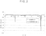
- the dQ/dV curve of the cathode active material was drawn by picking up the discharge capacities Q at 0.1 V intervals from the initial discharge curve data of the above cycle characteristics and plotting the variation dV of the voltage V and the variation dQ of the discharge capacity Q. Further, the presence and intensity of the peak are shown in Table 1. At this time, a ratio (I 1 / I 2 ) of an intensity (I 1 ) of one of the peaks with the highest voltage to an intensity (I 2 ) of the other of the peaks with the lowest voltage in the range of V 2 was 0.39.
- the cathode active material was obtained in the same manner as in Example 1 except that the burning temperature was 700 degrees C.
- the obtained cathode active material was measured and evaluated in the same manner as in Example 1. The results are shown in Tables 1 and 2. At this time, the ratio (I 1 / I 2 ) of the intensity (I 1 ) of one of the peaks with the highest voltage to the intensity (I 2 ) of the other of the peaks with the lowest voltage in the range of V 2 was 1.0.
- the cathode active material was obtained in the same manner as in Example 1 except that the burning temperature was 900 degrees C.
- the obtained cathode active material was measured and evaluated in the same manner as in Example 1. The results are shown in Tables 1 and 2. At this time, the ratio (I 1 / I 2 ) of the intensity (I 1 ) of one of the peaks with the highest voltage to the intensity (I 2 ) of the other of the peaks with the lowest voltage in the range of V 2 was 0.65.
- the cathode active material was obtained in the same manner as in Example 3 except that the ratio of the materials of the cathode active material was defined as below (molar ratio).
- the obtained cathode active material was measured and evaluated in the same manner as in Example 1. The results are shown in Fig. 1 and Tables 1 and 2. At this time, the ratio (I 1 / I 2 ) of the intensity (I 1 ) of one of the peaks with the highest voltage to the intensity (I 2 ) of the other of the peaks with the lowest voltage in the range of V 2 was 1.37.
- Li/Mn 0.67
- the cathode active material was obtained in the same manner as in Example 1 except that the ratio of the materials of the cathode active material was defined as below (molar ratio) and the burning temperature was 700 degrees C.
- a non-aqueous electrolyte secondary battery was produced according to the production method of the above-described non-aqueous electrolyte secondary battery and Li was electrochemically inserted. Specifically, electric current corresponding to 0.05 C was discharged from the non-aqueous electrolyte secondary battery to 2.5 V. Subsequently, the non-aqueous electrolyte secondary battery was disassembled to take out the cathode. Then, after being washed, the cathode was burnt at 480 degrees C to obtain a cathode active material.
- the X-ray diffraction pattern is shown in Fig. 3 .
- the cathode having been subjected to the X-ray diffraction measurement include the Al foil of the electrode. Accordingly, the X-ray diffraction pattern shown in Fig. 3 includes diffraction peaks derived from the Al foil of the electrode as represented by black circles in Fig. 3 .
- a cathode active material A having a layered structure was obtained in the same manner as in Example 3 except that the ratio of the materials of the cathode active material was defined as below (molar ratio).
- the obtained mixture C was measured and evaluated in the same manner as in Example 1. The results are shown in Tables 1 and 2. At this time, the ratio (I 1 / I 2 ) of the intensity (I 1 ) of one of the peaks with the highest voltage to the intensity (I 2 ) of the other of the peaks with the lowest voltage in the range of V 2 was 1.38.
Abstract
(1) the cathode active material contains Li, Mn, and Ni and has a spinel structure;
(2) a molar ratio (Ni / Mn) of Ni to Mn is in a range from 0.10 to 0.43;
(3) a molar ratio (Li / Mn) of Li to Mn is in a range from 0.70 to 1.80;
(4) the cathode active material has a peak in a range of 2θ = 19.7 to 22.5° in an X-ray diffraction pattern; and
(5) the cathode active material has at least one peak in a first voltage range of voltage V1 and at least two peaks in a second voltage range of voltage V2 in an initial dQ/dV curve of a discharge measured when a half cell is prepared using the cathode active material according to a predetermined process,
V1 = 2.72 to 2.90 [V]
V2 = 4.50 to 4.80 [V].
Description
- The present invention relates to a cathode active material for a non-aqueous electrolyte secondary battery, a cathode and a non-aqueous electrolyte secondary battery.
- Secondary batteries refer to batteries capable of repeated charging and discharging. Main components of the secondary batteries include a cathode, an anode and electrolytic solution. The secondary batteries can be roughly classified according to the electrolytic solution. Among the secondary batteries, a secondary battery using an organic solvent for the electrolytic solution is referred to as a non-aqueous electrolyte secondary battery. A typical non-aqueous electrolyte secondary battery is a lithium-ion secondary battery.
- The cathode of the non-aqueous electrolyte secondary battery usually contains an active material, an electrical conductive material, a binder, a current collector and the like. The active material refers to an electrochemically active substance. Examples of the cathode active material of the non-aqueous electrolyte secondary battery include LiCoO2, LiNiO2, and LiMn2O4.
- The cathode active material of the non-aqueous electrolyte secondary battery is categorized according to the structure of the active material. For instance, LiCoO2, LiNiO2 and the like are categorized into an active material of a layered structure. LiMn2O4 is categorized into an active material of a spinel structure.
- LiMn2O4, which has the above spinel structure, is less expensive and safer than LiCoO2, LiNiO2 and the like having the layered structure. However, the energy density per a unit mass of the LiMn2O4 having the spinel structure is smaller than that of LiCoO2, LiNiO2 and the like having the layered structure. In order to increase the energy density per a unit mass, it is necessary to raise an operating voltage of a battery or to increase a discharge capacity.
- In
Patent Literature 1, a part of Mn in LiMn2O4 is substituted by Ni to raise the operating voltage of a battery. In one of the Examples, it is disclosed that an operating potential of a battery can be raised to 4.5 V or more by substituting a part of Mn in LiMn2O4 by Ni to produce LiMn1.5Ni0.5O4. - In
Patent Literature 2, the discharge capacity of a battery is increased by providing an excessive Li in LiMn1.5Ni0.5O4. In one of Examples, it is disclosed that LiMn1.5Ni0.5O4 and LiI are reacted at 80 degrees C for 13 hours to synthesize Li2Mn1.5Ni0.5O4, which shows a discharge capacity in a range of 160 to 180 mAh/g. - In
Patent Literature 3, the discharge capacity of a battery is increased by reacting LiMn1.5Ni0.5O4 with LiI and subsequently annealing the reactant in a nitrogen atmosphere. In one of Examples, it is disclosed that Li2Mn1.5Ni0.5O4, which is synthesized by reacting LiMn1.5Ni0.5O4 and LiI and subsequently is annealed at 300 degrees C for five hours in a nitrogen atmosphere, shows a discharge capacity of approximately 240 mAh/g. - These related arts are, though showing high energy density, insufficient in terms of deterioration of the discharge capacity after repeated charging and discharging (cycle characteristics).
- Patent Literature 4 discloses that the cycle characteristics are improved by electrochemically inserting Li into LiMn1.5Ni0.5O4 to provide an excessive Li. However, though the method disclosed in Patent Literature 4 improves the cycle characteristics, sufficient discharge capacity cannot be obtained.
-
-
Patent Literature 1 -
JP 9-147867 A -
Patent Literature 2 -
JP 8-298115 A -
Patent Literature 3 -
WO 2014/124336 A - Patent Literature 4
-
JP 2009-176583 A - An object of the invention is to provide a cathode active material for a non-aqueous electrolyte secondary battery having excellent cycle characteristics, a cathode, and a non-aqueous electrolyte secondary battery having excellent cycle characteristics.
- In order to solve the above problem, an object of the invention is to provide a cathode active material for a non-aqueous electrolyte secondary battery, a cathode, and a non-aqueous electrolyte secondary battery as described below.
- A cathode active material for a non-aqueous electrolyte secondary battery according to an aspect of the invention satisfies conditions (1) to (5) below.
- (1) The cathode active material comprises Li, Mn, and Ni and has a spinel structure.
- (2) A molar ratio (Ni / Mn) of Ni to Mn is in a range from 0.10 to 0.43.
- (3) A molar ratio (Li / Mn) of Li to Mn is in a range from 0.70 to 1.80.
- (4) The cathode active material has a peak in a range of 2θ = 19.7 to 22.5 degrees in an X-ray diffraction pattern.
- (5) The cathode active material has at least one peak in a first voltage range of voltage V1 and at least two peaks in a second voltage range of voltage V2 in an initial dQ / dV curve of a discharge measured when a half cell is prepared using the cathode active material according to a process below.
- V1 = 2.72 to 2.90 [V]
- V2 = 4.50 to 4.80 [V]
- A cathode according to another aspect of the invention contains the cathode active material for a non-aqueous electrolyte secondary battery of the above aspect of the invention.
- A non-aqueous electrolyte secondary battery according to still another aspect of the invention includes the cathode of the above aspect of the invention.
- According to the above aspects of the invention, a cathode active material for a non-aqueous electrolyte secondary battery having excellent cycle characteristics, a cathode, and a non-aqueous electrolyte secondary battery having excellent cycle characteristics can be obtained.
-
-
Fig. 1 is a graph showing an X-ray diffraction pattern of a cathode active material obtained in Example 1 and Comparative 1. -
Fig. 2 is a graph showing an initial dQ/dV curve of cycle characteristics (abscissa axis: voltage (lithium based), ordinate axis: rate of a variation dQ of a discharge capacity Q to a variation dV of a voltage V) of the cathode active material obtained in each of Example 1 and Comparative 1. -
Fig. 3 is a graph showing an X-ray diffraction pattern of a cathode active material obtained in Comparative 3 prepared according to a method similar to a method disclosed in Patent Literature 4. - An exemplary embodiment of a cathode active material for a non-aqueous electrolyte secondary battery of the invention (referred to as "the present cathode active material" hereinafter) will be described below.
- The present cathode active material contains constituent elements including Li, Mn, and Ni. The contents of Li, Mn and Ni in the present cathode active material are defined in terms of a molar ratio (Ni / Mn) of Ni to Mn and a molar ratio (Li / Mn) of Li to Mn, as follows.
Ni/Mn = 0.10 to 0.43 [-]
Li / Mn = 0.70 to 1.80 [-] - It is more preferable that the molar ratios are in the following ranges.
Ni/Mn = 0.17 to 0.35 [-]
Li / Mn = 0.80 to 1.50 [-] - It is further preferable that the molar ratios are in the following ranges.
Ni / Mn = 0.20 to 0.35 [-]
Li / Mn = 1.20 to 1.50 [-]
The above ranges for Ni / Mn and Li / Mn are preferable because an initial discharge capacity is further enhanced. - The present cathode active material may contain an element(s) M other than Li, Mn, and Ni. The element(s) M is preferably selected from the following elements.
M = Na, K, Mg, Ca, Zn, Sr, Ba, Al, Ga, In, Si, Ge, Sn, P, Sb, B, S - The content of the element M is defined in terms of a molar ratio (M / Mn) of the element M to Mn, which is preferably in the following range.
M/Mn = 0.05 to 0.15 [-] - It is more preferable that the molar ratio is in the following range.
M / Mn = 0.05 to 0.07 [-] - When the ratio M / Mn is not within the above range, the initial discharge capacity and the cycle characteristics may be sometimes deteriorated.
- The present cathode active material has a spinel structure. The presence/absence of the spinel structure can be determined based on an X-ray diffraction pattern obtained by an Powder X-ray diffraction measurement. In the exemplary embodiment, it is determined that a cathode active material has a spinel structure when an X-ray diffraction pattern obtained by measuring the cathode active material under the later-described conditions for the Powder X-ray diffraction measurement has a peak within any one of the following ranges of 2θ.
- 2θ = 17.0 to 20.0 [°]
- 2θ = 35.0 to 37.5 [°]
- 2θ = 37.5 to 39.0 [°]
- 2θ = 41.5 to 46.0 [°]
- 2θ = 47.7 to 50.0 [°]
- The X-ray diffraction pattern of the present cathode active material has another peak in the following range of 2θ in addition to the above peaks derived from the spinel structure.
2θ = 19.7 to 22.5 [°] - It is not known to which structure the above peak is attributable. However, it is supposed that the structure of the present cathode active material is a mixed-crystal structure of the spinel structure and the layered structure. It is supposed that the present cathode active material having the mixed-crystal structure allows efficient donation and acceptance of electrons between lithium atoms in different crystal structures, so that the present cathode active material exhibits excellent cycle characteristics as compared to a mixture of a compound solely having the spinel structure and a compound solely having the layered structure. It should be noted that the X-ray diffraction pattern of lithium manganate having the spinel structure obtained by Li insertion (electrochemically or with a use of lithium iodide) as disclosed in the
above Patent Literatures 1 to 4 does not have a peak in the above 2θ range. - It is preferable that a ratio RP of a height of the peak to a height of a peak in the range of 2θ = 17.0 to 20.0° [(a height of a peak in a range of 2θ = 19.7 to 22.5°) / (a height of a peak in a range of 2θ = 17.0 to 20.0°) × 100] is in the following range.


- The present cathode active material having the RP within the above range is especially excellent in the initial discharge capacity and cycle characteristics.
- The shape of a charge-discharge curve of the present cathode active material greatly changes between an initial charge and discharge and a second and subsequent charges and discharges when the charges and discharges are repeated under later-described conditions for battery test. It is supposed that the change in the shape of the charge-discharge curve between the initial charge and discharge and the second and subsequent charges and discharges is attributable to a change in the structure of the cathode active material during the initial charge and discharge. The cathode active material of the exemplary embodiment exhibits a specific shape of the initial charge-discharge curve. The shape of the initial charge-discharge curve can be determined using the dQ/dV curve.
- The charge-discharge curve is drawn by plotting a data obtained when a battery is charged and discharged under the later-described conditions for the battery test in a graph having an abscissa axis representing a capacity Q and an ordinate axis representing a voltage V. The dQ/dV curve is drawn by plotting the data in a graph having an abscissa axis representing the voltage V and an ordinate axis representing dQ / dV (i.e. a ratio of a variation dQ of the capacity Q to a variation dV of the voltage V).
- The present cathode active material has one peak in the following range of voltage V1 and two peaks in the following range of voltage V2 in the initial dQ/dV curve (discharge).
- V1 = 2.72 to 2.90 [V]
- V2 = 4.50 to 4.80 [V]
- It is especially preferable that the peaks are present in the following ranges of voltages V1 and V2.
- V1 = 2.72 to 2.80 [V]
- V2 = 4.60 to 4.74 [V]
- When the peaks are present in the above ranges, excellent cycle characteristics can be obtained.
- In the present cathode active material, it is preferable that a ratio (I1 / I2) of an intensity (I1) of one of the peaks with the highest voltage to an intensity (I2) of the other of the peaks with the lowest voltage in the range of V2 in the initial dQ/dV curve (discharge) is within the following range.

- It is more preferable that the ratio (I1 / I2) is in the following range.

- When the ratio (I1 / I2) is within in the above range, excellent cycle characteristics can be obtained.
- A specific surface area (SSA) of the present cathode active material measured under measurement conditions of later-described BET specific surface area is preferably within the following range.
SSA = 1 to 40 [m2/g] - It is more preferable that the specific surface area is in the following range.
SSA = 1 to 30 [m2/g] - It is further preferable that the specific surface area is in the following range.
SSA = 4 to 30 [m2/g] - When the specific surface area is larger than 40 m2/g, the cycle characteristics may be disadvantageously lowered. In contrast, when the specific surface area is smaller than 1 m2/g, the initial discharge capacity may be disadvantageously lowered.
- Next, a manufacturing method of the present cathode active material (referred to as "the present manufacturing method" hereinafter) according to the exemplary embodiment will be described below.
- The present manufacturing method includes the following steps A and B.
- A. Material-mixing step (a step in which the materials are mixed to prepare a mixture)
- B. Burning step (a step in which the mixture is burnt to prepare the cathode active material of the exemplary embodiment)
- Known compounds containing Li, Mn, and/or Ni are usable as the material in the material-mixing step in the present manufacturing method. The known compounds usable as the material in the material-mixing step may contain the element(s) M.
- Examples of a compound containing Li include the compounds below. It should be noted that these compounds may further contain crystallization water. It should also be noted that these compounds may be used in combination at a predetermined ratio.
- Compound Containing Li
Li2CO3, LiOH, LiNO3, CH3COOLi, Li2SO4, Li3PO4 etc.
- It is preferable that the following compounds are used.
- More Preferable Compound Containing Li
Li2CO3, LiOH, LiNO3, CH3COOLi
The use of the above compounds is preferable because elements other than Li and O are removed when the above compounds are burnt. - Examples of a compound containing Mn include the compounds below. It should be noted that these compounds may further contain crystallization water. It should also be noted that these compounds may be used in combination at a predetermined ratio.
- Compound Containing Mn
MnO2, Mn2O3, Mn3O4, MnCO3, Mn(CH3COO)2, Mn(OH)2, Mn(NO3)2, MnSO4
etc. - It is preferable that the following compounds are used.
- More Preferable Compound Containing Mn
MnO2, Mn3O4, MnCO3, Mn(CH3COO)2, Mn(NO3)2, Mn(OH)2
- The use of the above compounds is preferable because elements other Mn and O are removed when the above compounds are burnt.
- Examples of a compound containing Ni include the compounds below. It should be noted that these compounds may further contain crystallization water. It should also be noted that these compounds may be used in combination at a predetermined ratio.
- Compound Containing Ni
NiO, Ni2O3, NiCO3, Ni(CH3COO)2, Ni(OH)2, Ni(NO3)2, NiSO4 etc.
- It is preferable that the following compounds are used.
- More Preferable Compound Containing Ni
NiO, Ni2O3, NiCO3, Ni(CH3COO)2, Ni(OH)2, Ni(NO3)2
- The use of the above compounds is preferable because elements other Ni and O are removed when the above compounds are burnt.
- As compounds containing the elements M, any known compounds containing M are usable. In the present manufacturing method, it is preferable that compounds from which elements other than M and O are removed after being burnt are used.
- In the present manufacturing method, the above materials are mixed to prepare a mixture in the material-mixing step. The materials may be mixed by dry mixing or wet mixing. In order to mix the materials, the following typically known mixers are usable.
- Agitation mixer, mixer, ball mill, jet mill, bead mill etc.
- A median size (d50) of grain size distribution of the mixture obtained in the material-mixing step, which is measured under the later-described measurement conditions of the grain size distribution, is preferably within the range below. It should be noted that the median size in a case of wet mixing refers to a median size of a slurry after being mixed (referred to as a mixed slurry hereinafter).
d50 = 0.1 to 0.5 [µm] - When the median size of the mixture is not within the above range, it is likely that the elements Li, Mn, Ni and M may be unevenly dispersed in the mixture. With the use of the mixture in which the elements Li, Mn, Ni and M are unevenly dispersed, unreacted material may remain in the cathode active material obtained after the burning step or unexpected by-product(s) may be generated. Such a cathode active material may cause energy density reduction or adverse affect on the cycle characteristics and thus is not preferable.
- In order to achieve the median size of the mixture, the material(s) may be preliminarily pulverized into a predetermined median size and may be subsequently mixed. Further, the materials may be pulverized into the above median size after the materials are mixed. The materials may be pulverized by dry pulverization or wet pulverization. It is preferable in the material-mixing step that wet pulverization is used. The wet pulverization can pulverize the materials more finely than the dry pulverization and thus is suitable for achieving the above median size of the mixture. In order to pulverize the materials by the wet pulverization, the following typically known pulverizers are usable.
- When the wet mixing and/or wet pulverization is used in the material-mixing step, the mixed slurry is dried to prepare the mixture. In order to dry the mixed slurry, the following typically known drying methods are usable.
- Evaporation drying, vacuum drying, decompression drying, spray drying, freeze drying etc.
- In the present manufacturing method, the mixture prepared in the material-mixing step is burnt in a burning step to prepare the cathode active material. In order to burn the mixture, the following typically known burning furnaces are usable.
- In the burning step, it is preferable that the mixture is burnt in the burning temperature range below. It should be noted that the burning temperature (T) refers to a temperature of the atmosphere in the burning furnace or the temperature of the mixture.
T = 500 to 900 [degrees C] - It is more preferable that the burning temperature is in the following range.
T = 700 to 850 [degrees C] - When the burning temperature is lower than 500 degrees C, it is possible that the cathode active material having the spinel structure cannot be obtained. When the burning temperature is higher than 900 degrees C, it is possible that the crystal may be overgrown or different phases may be generated. With the burning temperature ranging from 700 to 850 degrees C, a cathode active material having a high energy density and excellent cycle characteristics can be obtained.
- In the burning step, it is preferable that the temperature-increase rate is in the range below. It should be noted that the temperature-increase rate (Rup) is defined as an average ((T1 - T0) / (t1 - t0)) of time from when the temperature starts increasing (temperature: T0, time: t0) to when a predetermined burning temperature is reached (temperature: T1, time: t0).
Rup = 10 to 500 [degrees C/hr] - It is more preferable that the temperature-increase rate is kept in the following range.
Rup = 50 to 300 [degrees C/hr] - When the temperature-increase rate is smaller than 50 degrees C/hr, the productivity is unfavorably decreased due to the increase in the time required for increasing the temperature. In contrast, when the temperature-increase rate is larger than 300 degrees C/hr, it is likely that the temperature distribution in the mixture becomes uneven and thus the mixture cannot be uniformly burnt, which is not preferable.
- In the burning step, it is preferable that the burning temperature is kept in the burning time range below. It should be noted that the burning time (t) is defined as a time from when the predetermined burning temperature is reached to when the temperature becomes 50 or more degrees C below the predetermined burning temperature.
t = 0.1 to 24 [hr]
It is more preferable that the burning time is kept in the following range.
t = 0.1 to 10.0 [hr]
When the burning time is shorter than 0.1 hr, it is possible that the cathode active material having the spinel structure cannot be obtained, which is not preferable. When the burning time is longer than 10.0 hr, the productivity is unfavorably decreased. - In the burning step, it is preferable that the temperature-decrease rate is in the range below. It should be noted that the temperature-decrease rate (Rdown) is defined as an average ((T0 - 300) / (t0 - t1)) of time from when the temperature starts decreasing (temperature: T0, time: t0) to when the temperature reaches 300 degrees C (temperature: 300 degrees C, time: t1).
Rdown = 10 to 500 [degrees C/hr] - It is more preferable that the temperature-decrease rate is kept in the following range.
Rdown = 50 to 200 [degrees C/hr] - When the temperature-decrease rate is smaller than 50 degrees C/hr, the productivity is unfavorably decreased. In contrast, when the temperature-decrease rate is larger than 200 degrees C/hr, it is likely that sufficient oxygen for forming the spinel crystal structure is not supplied and oxygen deficiency structure is generated.
- A burning atmosphere in the burning step is not specifically limited. The burning step may be performed in the atmosphere, and may be performed in a circulating atmosphere.
- Next, a cathode according to the exemplary embodiment will be described below.
- The cathode of the exemplary embodiment contains the cathode active material of the exemplary embodiment. The cathode of the exemplary embodiment may contain, as necessary, components such as an active material other than the present cathode active material (referred to as "other active material" hereinafter), electrical conductive material, binder, and current collector.
- Examples of the other active material usable for the cathode of the exemplary embodiment include the conventionally known compounds mentioned below. It should be noted that any compound other than the compounds below can be used for the other active material for the cathode of the exemplary embodiment as long as the compound is capable of storing and discharging Li.
- Other Active Material
LiCoO2, LiNiO2, LiNi0.33Mn0.33Co0.33O2, LiMn2O4, LiMn1.5Ni0.5O4 etc.
- Examples of the electrical conductive material usable for the cathode of the exemplary embodiment include the conventionally known electrical conductive materials mentioned below. It should be noted that any electrical conductive material other than the electrical conductive materials mentioned below is usable for the cathode of the exemplary embodiment as long as the electrical conductive material is capable of conducting electrons.
- Active carbon, cokes, carbon black, acetylene black, graphite etc.
- Examples of the binders usable for the cathode of the exemplary embodiment include the conventionally known binders mentioned below. It should be noted that any binder other than the binders mentioned below is usable for the cathode of the exemplary embodiment as long as the binder is capable of binding the cathode active material, the electrical conductive material, the current collector and the like.
- PVDF (polyvinylidene fluoride), PTFE (polytetrafluoroethylene), fluororubber etc.
- Examples of the current collectors usable for the cathode of the exemplary embodiment include the conventionally known current collectors mentioned below. It should be noted that any current collector other than the current collectors mentioned below is usable for the cathode of the exemplary embodiment as long as the current collector is capable of conducting electrons and is not oxidized or reduced when being charged/discharged.
- Metal (e.g. aluminum, titanium and stainless steel) foil, expand metal, punching metal, metal foam, carbon cloth, carbon paper etc.
- Next, a non-aqueous electrolyte secondary battery according to the exemplary embodiment will be described below.
- The non-aqueous electrolyte secondary battery of the exemplary embodiment includes the cathode of the exemplary embodiment, an anode, an electrolyte and an exterior material. The non-aqueous electrolyte secondary battery of the exemplary embodiment may also include a separator as necessary. Further, the non-aqueous electrolyte secondary battery of the exemplary embodiment may also include a solid electrolyte instead of the electrolytic solution.
- The anode of the non-aqueous electrolyte secondary battery of the exemplary embodiment contains an anode active material. The anode of the exemplary embodiment may include a binder, a current collector and the like as necessary.
- Examples of the anode active materials usable for the anode of the non-aqueous electrolyte secondary battery of the exemplary embodiment include the conventionally known materials mentioned below. It should be noted that any compound other than the compounds below can be used for the material of the anode of the exemplary embodiment as long as the compound is capable of storing and discharging Li.
- Soft carbon, hard carbon, graphite powder, mesophase carbon fiber, mesophase microsphere, carbon material, metal Li, Li alloy, Li oxide, Li nitride etc.
- Examples of the binders usable for the anode of the non-aqueous electrolyte secondary battery according to the exemplary embodiment include the conventionally known binders mentioned below. It should be noted that any binder other than the binders mentioned below is usable for the anode of the exemplary embodiment as long as the binder is capable of binding the anode active material, the current collector and the like.
- Carboxymethyl cellulose, cross-linked rubber latex of styrene-butadiene, acrylic latex, PVDF etc.
- Examples of the current collectors usable for the anode of the non-aqueous electrolyte secondary battery according to the exemplary embodiment include the conventionally known current collectors mentioned below. It should be noted that any current collector other than the current collectors mentioned below is usable for the anode of the exemplary embodiment as long as the current collector is capable of conducting electrons and is not oxidized or reduced when being charged/discharged.
- Metal (e.g. copper, nickel and stainless steel) foil, expand metal, punching metal, metal foam, carbon cloth, carbon paper etc.
- The electrolytic solution usable for the non-aqueous electrolyte secondary battery of the exemplary embodiment includes a non-aqueous solvent and an electrolyte.
- Examples of the non-aqueous solvent usable for the electrolytic solution of the non-aqueous electrolyte secondary battery according to the exemplary embodiment includes the conventionally known non-aqueous solvent mentioned below. It should be noted that any non-aqueous solvent other than the non-aqueous solvents mentioned below is usable for the electrolytic solution of the exemplary embodiment as long as the non-aqueous solvent is capable of conducting Li ions and is not decomposed when being charged/discharged. In addition, these non-aqueous solvents may be mixed in use.
- Ethylene carbonate, propylene carbonate, 1,2-butylene carbonate, 2,3-butylene carbonate, 1,2-pentylene carbonate, 2,3-pentylene carbonate, trifluoromethylethylene carbonate, fluoroethylene carbonate, 4,5-difluoroethylene carbonate, γ-butyrolactone, γ-valerolactone, sulfolane, tetrahydrofuran, dioxane, ethylmethyl carbonate, dimethyl carbonate, diethyl carbonate, methylpropyl carbonate, methylisopropyl carbonate, dipropyl carbonate, methylbutyl carbonate, dibutyl carbonate, ethylpropyl carbonate, methyl trifluoroethyl carbonate, acetonitrile, dimethylether, methyl propionate, dimethoxyethane etc.
- Examples of the electrolyte usable for the electrolytic solution of the non-aqueous electrolyte secondary battery according to the exemplary embodiment include the conventionally known electrolytes mentioned below. It should be noted that any electrolyte other than the electrolytes mentioned below is usable for the electrolytic solution of the non-aqueous electrolyte secondary battery of the exemplary embodiment as long as the electrolyte contains Li and is dissolved in the non-aqueous solvent.
- LiPF6, LiClO4, LiAsF6, Li2SiF6, LiOSO2CkF(2k+1) [k is an integer ranging from 1 to 8], LiN(SO2CkF(2k+1))2 [k is an integer ranging from 1 to 8], LiPFn(CkF(2k+1))6-n [n is an integer ranging from 1 to 5, k is an integer ranging from 1 to 8], LiPF4(C2O4), LiPF2(C2O4)2, LiBF4, LiAlO4, LiAlCl4, Li2B12FbH12-b [b is an integer ranging from 0 to 3], LiBFq(CsF(2+1))4-q [q is an integer ranging from 1 to 3, s is an integer ranging from 1 to 8], LiB(C2O4)2, LiBF2(C2O4), LiB(C3O4H2)2, LiPF4(C2O2) etc.
- Examples of the separator usable for the non-aqueous electrolyte secondary battery of the exemplary embodiment include the conventionally known separators mentioned below. It should be noted that any separator other than the separator mentioned below is usable for the non-aqueous electrolyte secondary battery of the exemplary embodiment as long as Li ions can permeate through the separator and the separator can electrically isolate the cathode from the anode.
- A structure (non-woven fabric, paper, porous membrane etc.) including a mixture of an inorganic material (e.g. alumina and silica), and cellulose, aromatic polyamide or a resin such as fluorocarbon resin and polyolefin
- Examples of the exterior material usable for the non-aqueous electrolyte secondary battery of the exemplary embodiment include the conventionally known exterior materials mentioned below. It should be noted that any exterior material other than the exterior materials mentioned below is usable for the non-aqueous electrolyte secondary battery of the exemplary embodiment as long as the exterior material is not deteriorated even when the cathode, the anode, the electrolytic solution and the like are enclosed.
- Metal such as stainless steel and aluminum, a laminate film (metal film covered with a resin), etc.
- The invention will be described in detail below with reference to Examples. However, it should be understood that the scope of the invention is by no means limited by the Examples.
- Lithium source in a form of LiOH·H2O, nickel source in a form of NiO, and manganese source in a form of MnO2 were prepared. These materials were weighed so that the molar ratio below was reached. The weighed materials were stirred and mixed in an ion-exchange water to prepare a mixed slurry so that the material concentration became 33.3 mass%.
Li:Mn:Ni=2.0: 1.5 :0.5
Ni/Mn=0.33
Li/Mn=1.33 - The mixed slurry obtained in the above material-mixing step was pulverized while being stirred using a wet pulverization machine (manufactured by Ashizawa Finetech Ltd.: Stirring Mill LABSTAR LMZ-06). The mixed slurry was pulverized until the median size of the materials in the mixed slurry became 0.35 µm.
- The median size of the materials in the mixed slurry was measured using a laser-diffraction/scattering particle-size distribution measurement machine (manufactured by HORIBA, Ltd.: LA-950 particle size distribution analyzer). Specifically, after a small amount of the mixed slurry was collected and sodium hexametaphosphate was added thereto, sonication was applied. Subsequently, after the sonicated mixed slurry was dropped on the laser-diffraction/scattering particle-size distribution measurement machine so that transmissivity was adjusted to be in a range from 40 to 60%, the particle-size distribution was measured.
- The mixed slurry obtained in the above wet pulverization step was spray-dried using a nozzle spray drier (manufactured by Ohkawara Kakohki Co., Ltd.: L-8 spray drier). Air was used for the drying gas of the nozzle spray drier. After regulating the flow rate of the drying gas so that a cyclone differential pressure became 0.7 kPa, the temperature of the drying gas was set at 200 degrees C. After the temperature of the drying gas reached 200 degrees C, the mixed slurry was introduced at a rate of 2.5 kg/h. The nozzle spray pressure at this time was 1.5 MPa.
- The mixture obtained in the above spray drying step was burnt under the following burning conditions to prepare a cathode active material.
- Burning furnace: muffle furnace
- Atmosphere: air
- Loaded amount: 30 g
- Burning temperature: 600 degrees C
- Temperature-increase rate: 150 [degrees C/hr]
- Burning time: 6 hrs
- Temperature-decrease rate: 100 [degrees C/hr]
- The cathode active material obtained in the above burning step was subjected to a powder X-ray diffraction measurement under the following conditions.
- X-ray diffraction machine: SmartLab (manufactured by Rigaku Corporation)
- X-ray source: Cu-Kα ray
- Acceleration voltage, current: 45 KV, 200 mA
- Light-receiving slit: 13 mm
- Scanning speed: 5.1 degrees/min
- Step width: 0.02°
- Measurement range (2θ): 5 to 90°
- An X-ray diffraction pattern obtained by subjecting the cathode active material to the powder X-ray diffraction measurement is shown in
Fig. 1 . The X-ray diffraction pattern shown inFig. 1 has peaks in the ranges of 2θ = 17.0 to 20.0°, 35.0 to 37.5°, 37.5 to 39.0°, 2θ = 41.5 to 46.0°, and 2θ = 47.7 to 50.0°. Accordingly, the cathode active material is supposed to have a spinel structure. Further, the cathode active material has a peak other than spinel in a range 2θ = 19.7 to 22.5°. It should be noted that the presence of the peaks is judged based on a peak data detected by reading measurement data into an integrated powder X-ray analysis software PDXL (produced by Rigaku Corporation) to automatically perform data processing such as peak detection and background-noise removal under default conditions. Further, a height of the peak in the range of 2θ = 17.0 to 20.0° and a height of the peak in the range of 2θ = 19.7 to 22.5° were obtained based on the peak data and a ratio Rp [(the height of the peak in the range of 2θ = 19.7 to 22.5°) / (the height of the peak in the range of 2θ = 17.0 to 20.0°) × 100] was calculated. - The cathode active material obtained in the above burning step was subjected to a BET specific surface area measurement under the following conditions.
-
- Sample amount: 1 g
- Pre-treatment: 300 degrees C- 1 hr
- Measurement results are shown in Table 1.
- A half cell including a non-aqueous electrolyte secondary battery having a lithium electrode (i.e. an anode) opposite to the cathode was prepared to evaluate the electrochemical properties of the present cathode active material (initial discharge capacity, cycle characteristics, dQ/dV curve).
- The cathode active material obtained in the above burning step, an electrical conductive material in a form of acetylene black and KS6 and a binder in a form of polyvinylidene fluoride were respectively weighed to be a mass ratio of 80:5:5:10. The above cathode active material, the electrical conductive material and the binder were mixed in N-methyl-2-pyrrolidone (NMP) to prepare a cathode coating liquid. The cathode coating liquid was applied on the current collector in a form of aluminum foil. After being dried, the current collector was rolled to have a film thickness in a range from 35 to 45 µm. The actual film thickness was 40 µm. Subsequently, the current collector was punched in a diameter of 14 mm, and was vacuum-dried to obtain a cathode.
- The above cathode and the anode (metal lithium foil: thickness 0.2 mm) were layered in a coin-type cell case through a separator (glass filter). Subsequently, an electrolytic solution in which LiPF6 was dissolved at 1 mol/L concentration in a mixture solvent of ethylene carbonate and ethylmethyl carbonate (volume ratio 1:2) was poured in the coin-type cell case to produce the half cell.
- Evaluation of Battery
- The half cell produced according to the above method was evaluated in terms of the initial discharge capacity, cycle characteristics and dQ/dV curve according to the methods below.
- Electric current corresponding to 0.05 C was charged to the opposite electrode (lithium electrode) to 4.8 V. Subsequently, an electric current corresponding to 0.2 C was discharged from the battery to 2.0 V. The discharge capacity at this time was defined as an initial discharge capacity. The results are shown in Table 2. The discharge capacity at this time is converted to a capacity per mass of the cathode active material. It should be noted that the electric current corresponding to 0.05 C refers to a current density capable of completely discharging a battery in 20 hours.
- Herein, the cycle characteristics are evaluated in terms of the discharge capacity after 50 cycles of charging and discharging. Similar to the measurement of the discharge capacity, electric current corresponding to 0.05 C was charged to 4.8 V. Subsequently, an electric current corresponding to 0.2 C was discharged from the battery to 2.0 V. In the second and subsequent cycles, an electric current corresponding to 0.2 C was repeatedly applied to/discharged from the battery in a range from 2.0 to 4.8 V, and the discharge capacity after 50 cycles was measured. It should be noted that the electric current corresponding to 0.2 C refers to a current density capable of completely discharging a battery in 5 hours.

- The dQ/dV curve is a curve defined in a graph having an abscissa axis representing the voltage (based on lithium) and an ordinate axis representing a ratio of a variation dQ of the discharge capacity Q to a variation dV of the voltage V. Initial dQ/dV curve is shown in
Fig. 2 . It should be noted that the dQ/dV curve of the cathode active material was drawn by picking up the discharge capacities Q at 0.1 V intervals from the initial discharge curve data of the above cycle characteristics and plotting the variation dV of the voltage V and the variation dQ of the discharge capacity Q. Further, the presence and intensity of the peak are shown in Table 1. At this time, a ratio (I1 / I2) of an intensity (I1) of one of the peaks with the highest voltage to an intensity (I2) of the other of the peaks with the lowest voltage in the range of V2 was 0.39. - The cathode active material was obtained in the same manner as in Example 1 except that the burning temperature was 700 degrees C. The obtained cathode active material was measured and evaluated in the same manner as in Example 1. The results are shown in Tables 1 and 2. At this time, the ratio (I1 / I2) of the intensity (I1) of one of the peaks with the highest voltage to the intensity (I2) of the other of the peaks with the lowest voltage in the range of V2 was 1.0.
- The cathode active material was obtained in the same manner as in Example 1 except that the burning temperature was 900 degrees C. The obtained cathode active material was measured and evaluated in the same manner as in Example 1. The results are shown in Tables 1 and 2. At this time, the ratio (I1 / I2) of the intensity (I1) of one of the peaks with the highest voltage to the intensity (I2) of the other of the peaks with the lowest voltage in the range of V2 was 0.65.
- The cathode active material was obtained in the same manner as in Example 3 except that the ratio of the materials of the cathode active material was defined as below (molar ratio). The obtained cathode active material was measured and evaluated in the same manner as in Example 1. The results are shown in
Fig. 1 and Tables 1 and 2. At this time, the ratio (I1 / I2) of the intensity (I1) of one of the peaks with the highest voltage to the intensity (I2) of the other of the peaks with the lowest voltage in the range of V2 was 1.37.
Li:Mn:Ni = 1.0:1.5:0.5
Ni/Mn = 0.33
Li/Mn = 0.67 - The cathode active material was obtained in the same manner as in Example 1 except that the ratio of the materials of the cathode active material was defined as below (molar ratio) and the burning temperature was 700 degrees C. The obtained cathode active material was measured and evaluated in the same manner as in Example 1. The results are shown in Tables 1 and 2.
Li:Mn:Ni = 2.8:1.5:0.5
Ni/Mn = 0.33 Li/Mn=1.87 - Using the cathode active material obtained in the same manner as
Comparative 1, a non-aqueous electrolyte secondary battery was produced according to the production method of the above-described non-aqueous electrolyte secondary battery and Li was electrochemically inserted. Specifically, electric current corresponding to 0.05 C was discharged from the non-aqueous electrolyte secondary battery to 2.5 V. Subsequently, the non-aqueous electrolyte secondary battery was disassembled to take out the cathode. Then, after being washed, the cathode was burnt at 480 degrees C to obtain a cathode active material. - The obtained cathode active material was measured and evaluated in the same manner as in Example 1. At this time, the ratio (I1 / I2) of the intensity (I1) of one of the peaks with the highest voltage to the intensity (I2) of the other of the peaks with the lowest voltage in the range of V2 was 1.89.
Li:Mn:Ni = 1.2:1.5:0.5
Ni/Mn = 0.33
Li/Mn = 0.8
It should be noted that the cathode taken out and washed was directly set to the X-ray diffraction machine only during the X-ray diffraction measurement to be measured in a range of 2θ = 15 to 70°. The results are shown in Tables 1 and 2. Further, the X-ray diffraction pattern is shown inFig. 3 . It should be noted that the cathode having been subjected to the X-ray diffraction measurement include the Al foil of the electrode. Accordingly, the X-ray diffraction pattern shown inFig. 3 includes diffraction peaks derived from the Al foil of the electrode as represented by black circles inFig. 3 . - A cathode active material A having a layered structure was obtained in the same manner as in Example 3 except that the ratio of the materials of the cathode active material was defined as below (molar ratio). The obtained cathode active material A was mixed with a cathode active material B having the spinel structure obtained in
Comparative 1 at a weight ratio of A:B = 6:4 to obtain a mixture C. The obtained mixture C was measured and evaluated in the same manner as in Example 1. The results are shown in Tables 1 and 2. At this time, the ratio (I1 / I2) of the intensity (I1) of one of the peaks with the highest voltage to the intensity (I2) of the other of the peaks with the lowest voltage in the range of V2 was 1.38.
Cathode Active Material A Having Layered Structure
Li:Mn:Ni = 3:1.5:0.5
Ni/Mn = 0.33
Li/Mn = 0.8
Cathode Active Material B Having Spinel Structure
Li:Mn:Ni = 1.0:1.5:0.5
Ni/Mn = 0.33
Li/Mn = 0.67
Mixture C
Li:Mn:Ni = 2.2:1.5:0.5
Ni/Mn = 0.33
Li/Mn = 1.47Table 1 Compo sition Buming Temperature X-ray Diffraction Specific Surface Area dQ/dV Curve Spinel Structure Peak in 2θ= 19.7 to 22.5° Rp Peak of V1 (Voltage, Intensity) Peak of V2 (Voltage, Intensity) Li Mn Ni Ni/Mn Li/Mn [Degrees C] [m2/g] Ex. 1 2.0 1.5 0.5 0.33 133 600 Yes Yes 5% 25.1 Peak 1(2.78, -1.3997) Peak 1(4.66, -0.5648) Peak 2(4.73, -0.2201) Ex. 2 2.0 1.5 0.5 0.33 1.33 700 Yes Yes 5% 15.4 Peak 1(2.75, -1.3965) Peak 1(4.70, -1.1021) Peak 2(4.72, -1.1021) Ex.3 2.0 1.5 0.5 0.33 1.33 900 Yes Yes 7% 1.3 Peak 1(2.72, -0.3045) Peak 1(4.67,-1.2581) Peak 2(4.71, -0.8123) Comp. 1 1.0 1.5 0.5 0.33 0.67 900 Yes No - 0.8 Peak 1(2.70,-0.5197) Peak 1(4.68,-22145) Peak 2(4.72, -3.0264) Comp.2 2.8 1.5 0.5 033 1.87 700 No Yes 8% 14.5 None None Comp.3 1.2 1.5 0.5 0.33 0.80 900 Yes No - 0.8 Peak 1(2.67,-1.5250) Peak 1(4.69,-2.1534) Peak 2(4.73, -4.0722) Comp. 4 2.2 1.5 0.5 0.33 1.47 900 Yes Yes 8% 2.7 Peak 1(2.70,-02604) Peak 1(4.67,-0.5361) Peak 2(4.71, -0.7373) Table 2 Initial Discharge Capacity Discharge Capacity after 50 Cycles [mAh/g] [mAh/g] Ex. 1 290 188 Ex. 2 278 200 Ex. 3 110 220 Comp. 1 191 111 Comp. 2 250 172 Comp. 3 188 105 Comp. 4 241 175
Claims (4)
- A cathode active material for a non-aqueous electrolyte secondary battery, wherein the cathode active material satisfies conditions (1) to (5) below:(1) the cathode active material comprises Li, Mn, and Ni and has a spinel structure;(2) a molar ratio (Ni / Mn) of Ni to Mn is in a range from 0.10 to 0.43;(3) a molar ratio (Li / Mn) of Li to Mn is in a range from 0.70 to 1.80;(4) the cathode active material has a peak in a range of 2θ = 19.7 to 22.5° in an X-ray diffraction pattern; and(5) the cathode active material has at least one peak in a first voltage range of voltage V1 and at least two peaks in a second voltage range of voltage V2 in an initial dQ/dV curve of a discharge measured in a half cell prepared using the cathode active material according to a process below,wherein the process comprises:V1 = 2.72 to 2.90 [V]V2 = 4.50 to 4.80 [V]weighing the cathode active material, an electrical conductive material in a form of acetylene black and KS6 and a binder in a form of polyvinylidene fluoride to be a mass ratio of 80:5:5:10;mixing the cathode active material, the electrical conductive material and the binder in N-methyl-2-pyrrolidone (NMP) to prepare a cathode coating liquid;applying the cathode coating liquid on a current collector in a form of an aluminum foil and, after drying the cathode coating liquid, rolling the current collector so that the current collector has a film thickness in a range from 35 to 45 µm;punching the current collector in a diameter of 14 mm, and vacuum-drying the current collector to obtain a cathode;layering the cathode and an anode in a form of a metal lithium foil having a thickness of 0.2 mm in a coin-type cell case through a separator in a form of a glass filter;pouring an electrolytic solution in which LiPF6 was dissolved at 1 mol/L concentration in a mixture solvent of ethylene carbonate and ethylmethyl carbonate (volume ratio 1:2) in the coin-type cell case to produce the half cell;charging the half cell with an electric current corresponding to 0.05 C to 4.8 V and discharging the half cell with an electric current corresponding to 0.2 C to 2.0 V; and drawing a dQ/dV curve by picking up discharge capacities Q at 0.1 V intervals from an initial discharge curve data obtained in the charging and discharging and plotting a variation dV of a voltage V and a variation dQ of a discharge capacity Q.
- The cathode active material for the non-aqueous electrolyte secondary battery according to claim 1, wherein the ratio (I1 / I2) of the intensity (I1) of one of the peaks with the highest voltage to the intensity (I2) of the other of the peaks with the lowest voltage in the range of V2 is in a range of

- A cathode comprising the cathode active material for the non-aqueous electrolyte secondary battery according to claim 1 or 2.
- A non-aqueous electrolyte secondary battery comprising the cathode according to claim 3.
Applications Claiming Priority (2)
| Application Number | Priority Date | Filing Date | Title |
|---|---|---|---|
| JP2015042894 | 2015-03-04 | ||
| PCT/JP2016/056852 WO2016140352A1 (en) | 2015-03-04 | 2016-03-04 | Positive electrode active substance for non-aqueous electrolyte secondary battery, positive electrode and non-aqueous electrolyte secondary battery |
Publications (2)
| Publication Number | Publication Date |
|---|---|
| EP3267516A1 true EP3267516A1 (en) | 2018-01-10 |
| EP3267516A4 EP3267516A4 (en) | 2018-12-05 |
Family
ID=56848582
Family Applications (1)
| Application Number | Title | Priority Date | Filing Date |
|---|---|---|---|
| EP16759044.7A Withdrawn EP3267516A4 (en) | 2015-03-04 | 2016-03-04 | Positive electrode active substance for non-aqueous electrolyte secondary battery, positive electrode and non-aqueous electrolyte secondary battery |
Country Status (6)
| Country | Link |
|---|---|
| US (1) | US10236505B2 (en) |
| EP (1) | EP3267516A4 (en) |
| JP (1) | JPWO2016140352A1 (en) |
| KR (1) | KR20170118775A (en) |
| CN (1) | CN107431202A (en) |
| WO (1) | WO2016140352A1 (en) |
Families Citing this family (2)
| Publication number | Priority date | Publication date | Assignee | Title |
|---|---|---|---|---|
| KR102278388B1 (en) * | 2017-09-28 | 2021-07-19 | 가부시키가이샤 히타치세이사쿠쇼 | Semi-Secondary Battery and Secondary Battery |
| JP6998176B2 (en) * | 2017-11-01 | 2022-01-18 | 株式会社豊田中央研究所 | Positive electrode active material, positive electrode and lithium secondary battery |
Family Cites Families (11)
| Publication number | Priority date | Publication date | Assignee | Title |
|---|---|---|---|---|
| JP3606289B2 (en) | 1995-04-26 | 2005-01-05 | 日本電池株式会社 | Cathode active material for lithium battery and method for producing the same |
| CA2158242C (en) | 1995-09-13 | 2000-08-15 | Qiming Zhong | High voltage insertion compounds for lithium batteries |
| EP2067198A2 (en) * | 2006-09-25 | 2009-06-10 | Board of Regents, The University of Texas System | Cation-substituted spinel oxide and oxyfluoride cathodes for lithium ion batteries |
| JP5278994B2 (en) | 2008-01-25 | 2013-09-04 | Necエナジーデバイス株式会社 | Lithium secondary battery |
| FR2932175B1 (en) * | 2008-06-05 | 2011-06-03 | Commissariat Energie Atomique | POSITIVE ELECTRODE MATERIAL FORMED OF A LAMELLAR TYPE OXIDE FOR LITHIUM ACCUMULATOR. |
| CN102484249A (en) * | 2009-08-27 | 2012-05-30 | 安维亚系统公司 | Layer-layer lithium rich complex metal oxides with high specific capacity and excellent cycling |
| US9123959B2 (en) | 2013-02-11 | 2015-09-01 | Wildcat Discovery Technologies, Inc. | High energy cathode material |
| SI3011619T1 (en) * | 2013-06-21 | 2018-10-30 | Cabot Corporation | Active materials for lithium ion batteries |
| JP6200079B2 (en) * | 2014-05-12 | 2017-09-20 | 旭化成株式会社 | Lithium manganese nickel composite oxide, method for producing the same, and active material, positive electrode and nonaqueous electrolyte secondary battery for nonaqueous electrolyte secondary battery including the same |
| JP6369126B2 (en) * | 2014-05-21 | 2018-08-08 | 戸田工業株式会社 | Positive electrode active material powder for non-aqueous electrolyte secondary battery, method for producing the same, and non-aqueous electrolyte secondary battery |
| CN104319392A (en) * | 2014-10-23 | 2015-01-28 | 天津理工大学 | Modified spinel type lithium battery cathode material and preparation method thereof |
-
2016
- 2016-03-04 KR KR1020177024936A patent/KR20170118775A/en unknown
- 2016-03-04 EP EP16759044.7A patent/EP3267516A4/en not_active Withdrawn
- 2016-03-04 CN CN201680013716.2A patent/CN107431202A/en active Pending
- 2016-03-04 WO PCT/JP2016/056852 patent/WO2016140352A1/en active Application Filing
- 2016-03-04 JP JP2017503735A patent/JPWO2016140352A1/en active Pending
- 2016-03-04 US US15/554,198 patent/US10236505B2/en not_active Expired - Fee Related
Also Published As
| Publication number | Publication date |
|---|---|
| US20180034052A1 (en) | 2018-02-01 |
| KR20170118775A (en) | 2017-10-25 |
| US10236505B2 (en) | 2019-03-19 |
| WO2016140352A1 (en) | 2016-09-09 |
| CN107431202A (en) | 2017-12-01 |
| EP3267516A4 (en) | 2018-12-05 |
| JPWO2016140352A1 (en) | 2018-01-18 |
Similar Documents
| Publication | Publication Date | Title |
|---|---|---|
| US11108043B2 (en) | Method for producing positive electrode active material for nonaqueous electrolyte secondary battery | |
| EP3370285B1 (en) | Positive electrode active material for nonaqueous electrolyte secondary batteries and nonaqueous electrolyte secondary battery using said positive electrode active material | |
| CN107112522B (en) | Negative electrode active material for nonaqueous electrolyte secondary battery and nonaqueous electrolyte secondary battery | |
| EP2477258B1 (en) | Cathode active material, cathode and lithium battery including cathode active material, and method of preparing the cathode active material | |
| CN107112521B (en) | Negative electrode active material for nonaqueous electrolyte secondary battery and nonaqueous electrolyte secondary battery | |
| EP3032619A1 (en) | Cathode material for lithium secondary battery, and lithium secondary battery containing same | |
| JP6847667B2 (en) | Negative electrode active material for non-aqueous electrolyte secondary batteries and non-aqueous electrolyte secondary batteries | |
| US11715822B2 (en) | Negative electrode active material for non-aqueous electrolyte secondary cell, and non-aqueous electrolyte secondary cell | |
| EP3267517A1 (en) | Positive electrode active substance for non-aqueous electrolyte secondary battery, and method for producing same | |
| KR20160030878A (en) | Positive-electrode active material for non-aqueous electrolyte secondary battery, method for producing said positive-electrode active material for non-aqueous electrolyte secondary battery, and non-aqueous electrolyte secondary battery using said positive-electrode active material for non-aqueous electrolyte secondary battery | |
| US11482700B2 (en) | Positive electrode active material for nonaqueous electrolyte secondary batteries and method for producing positive electrode active material for nonaqueous electrolyte secondary batteries | |
| KR102115685B1 (en) | Precursor for lithium transition metal oxide cathode materials for rechargeable batteries | |
| US20150311505A1 (en) | LMFP Cathode Materials with Improved Electrochemical Performance | |
| EP3678236B1 (en) | Positive electrode active material for lithium secondary batteries, positive electrode for lithium secondary batteries, and lithium secondary battery | |
| US11735728B2 (en) | Cathode active material for non-aqueous electrolyte secondary battery and method of manufacturing cathode active material for non-aqueous electrolyte secondary battery | |
| EP3748738A1 (en) | Negative electrode active substance for secondary battery, and secondary battery | |
| EP3716371A1 (en) | Negative electrode active substance for secondary battery, and secondary battery | |
| KR20190001191A (en) | Positive Electrode Material for Lithium-Ion Batteries and Lithium-Ion Battery Having the Same | |
| JPWO2019107032A1 (en) | Negative electrode active material for lithium-ion batteries and lithium-ion batteries | |
| EP3748739A1 (en) | Negative electrode active material for secondary cell, and secondary cell | |
| CN107210435B (en) | Negative electrode active material for nonaqueous electrolyte secondary battery and nonaqueous electrolyte secondary battery | |
| EP3709397B1 (en) | Positive electrode for nonaqueous electrolyte battery and nonaqueous electrolyte battery | |
| EP3415467B1 (en) | Method for manufacturing vanadium lithium phosphate | |
| US10236505B2 (en) | Positive electrode active substance for non-aqueous electrolyte secondary battery, positive electrode and non-aqueous electrolyte secondary battery | |
| JP2000128546A (en) | Production of positive electrode active material nickel acid lithium for nun-aqueous secondary battery and non- aqueous secondary battery |
Legal Events
| Date | Code | Title | Description |
|---|---|---|---|
| PUAI | Public reference made under article 153(3) epc to a published international application that has entered the european phase |
Free format text: ORIGINAL CODE: 0009012 |
|
| 17P | Request for examination filed |
Effective date: 20170831 |
|
| AK | Designated contracting states |
Kind code of ref document: A1 Designated state(s): AL AT BE BG CH CY CZ DE DK EE ES FI FR GB GR HR HU IE IS IT LI LT LU LV MC MK MT NL NO PL PT RO RS SE SI SK SM TR |
|
| AX | Request for extension of the european patent |
Extension state: BA ME |
|
| DAV | Request for validation of the european patent (deleted) | ||
| DAX | Request for extension of the european patent (deleted) | ||
| A4 | Supplementary search report drawn up and despatched |
Effective date: 20181030 |
|
| RIC1 | Information provided on ipc code assigned before grant |
Ipc: C01G 45/12 20060101ALI20181024BHEP Ipc: H01M 4/525 20100101ALI20181024BHEP Ipc: H01M 10/0525 20100101ALI20181024BHEP Ipc: H01M 4/505 20100101AFI20181024BHEP |
|
| STAA | Information on the status of an ep patent application or granted ep patent |
Free format text: STATUS: THE APPLICATION IS DEEMED TO BE WITHDRAWN |
|
| 18D | Application deemed to be withdrawn |
Effective date: 20190528 |