EP3267340B1 - Netzwerksimulationsvorrichtung, netzwerksimulationsverfahren sowie netzwerksimulationsprogramm - Google Patents
Netzwerksimulationsvorrichtung, netzwerksimulationsverfahren sowie netzwerksimulationsprogramm Download PDFInfo
- Publication number
- EP3267340B1 EP3267340B1 EP16758675.9A EP16758675A EP3267340B1 EP 3267340 B1 EP3267340 B1 EP 3267340B1 EP 16758675 A EP16758675 A EP 16758675A EP 3267340 B1 EP3267340 B1 EP 3267340B1
- Authority
- EP
- European Patent Office
- Prior art keywords
- pipe network
- user
- model information
- input
- accept
- Prior art date
- Legal status (The legal status is an assumption and is not a legal conclusion. Google has not performed a legal analysis and makes no representation as to the accuracy of the status listed.)
- Active
Links
Images






Classifications
-
- G—PHYSICS
- G06—COMPUTING OR CALCULATING; COUNTING
- G06F—ELECTRIC DIGITAL DATA PROCESSING
- G06F30/00—Computer-aided design [CAD]
- G06F30/10—Geometric CAD
- G06F30/18—Network design, e.g. design based on topological or interconnect aspects of utility systems, piping, heating ventilation air conditioning [HVAC] or cabling
-
- G—PHYSICS
- G06—COMPUTING OR CALCULATING; COUNTING
- G06F—ELECTRIC DIGITAL DATA PROCESSING
- G06F30/00—Computer-aided design [CAD]
- G06F30/10—Geometric CAD
- G06F30/12—Geometric CAD characterised by design entry means specially adapted for CAD, e.g. graphical user interfaces [GUI] specially adapted for CAD
-
- G—PHYSICS
- G06—COMPUTING OR CALCULATING; COUNTING
- G06F—ELECTRIC DIGITAL DATA PROCESSING
- G06F30/00—Computer-aided design [CAD]
- G06F30/10—Geometric CAD
- G06F30/13—Architectural design, e.g. computer-aided architectural design [CAAD] related to design of buildings, bridges, landscapes, production plants or roads
-
- G—PHYSICS
- G06—COMPUTING OR CALCULATING; COUNTING
- G06F—ELECTRIC DIGITAL DATA PROCESSING
- G06F30/00—Computer-aided design [CAD]
- G06F30/20—Design optimisation, verification or simulation
- G06F30/28—Design optimisation, verification or simulation using fluid dynamics, e.g. using Navier-Stokes equations or computational fluid dynamics [CFD]
-
- G—PHYSICS
- G06—COMPUTING OR CALCULATING; COUNTING
- G06T—IMAGE DATA PROCESSING OR GENERATION, IN GENERAL
- G06T19/00—Manipulating three-dimensional [3D] models or images for computer graphics
-
- G—PHYSICS
- G06—COMPUTING OR CALCULATING; COUNTING
- G06F—ELECTRIC DIGITAL DATA PROCESSING
- G06F2113/00—Details relating to the application field
- G06F2113/14—Pipes
Definitions
- the present invention relates to a network simulation device, a network simulation method, and a network simulation program.
- a production site such as a factory has various types of facilities, and these different types of facilities have various power sources.
- Compressed air which is obtained by compressing the atmospheric air, is easily available, and is thus widely used as a power source for driving, for example, a pneumatic tool, a pneumatic press, a pneumatic brake, and a spray gun.
- a terminal instrument an instrument driven with compressed air is referred to as a "terminal instrument.”
- Compressed air is produced with a compressor and is supplied to terminal instruments via a pipe network provided in a factory. It is said in general that the power consumption of the compressor accounts for 20% to 30% of that of the entire factory. Hence, it is important to reduce power consumed by the compressor from the viewpoint not only of environmental sustainment and resource conservation, but also of corporate management.
- a computer aided design (CAD) device of Patent Literature 1 is equipped with a pressure loss calculation function for a flow path model.
- the CAD device creates a flow path model with an input function which the device itself originally provides as a CAD device.
- the device displays the flow path model on a screen, accepts selection of a system constituting the flow path model by a user, and calculates the pressure loss of the system.
- Patent Literature 1 Japanese Patent Application Publication No. 2011-248703 ( Fig. 14 )
- the actual pipe network of a factory or the like includes an "upflow” part and a “downflow” part and is arranged three dimensionally in order to avoid obstacles.
- a user of the CAD device of Patent Literature 1 creates a pipe network model (flow path model) based on a pipe network arranged three dimensionally. To this end, it is necessary for the user to perform three-dimensional operations on the CAD device. It requires significant effort for the user to acquire expertise on the three-dimensional operations on the CAD device.
- the present invention aims to create a network model easily and promptly without three-dimensional operations.
- the invention is defined in the independent device, method and computer program claims 1, 2 and 3 accordingly.
- the present invention makes it possible to create a network model easily and promptly without three-dimensional operations.
- the network simulation device 1 (hereinafter also referred to as the "NWS (network simulation) device") is operated by, for example, a corporation which owns a factory or a service company which services a factory.
- the NWS device 1 is a general computer, and includes a central control device 11, an input device 12, an output device 13, a main storage device 14, and an auxiliary storage device 15. These devices are connected to one another via a bus.
- the auxiliary storage device 15 stores pipe network model information 31, 32, and 33 (their details are described later) .
- a model information creation unit 21 and a simulation running unit 22 in the main storage device 14 are each a program.
- a "*** unit" used as the subject of a sentence means that the central control device 11 reads programs from the auxiliary storage device 15, loads the programs onto the main storage device 14, and executes the functions of the programs (their details are described later).
- FIG. 2 A pipe network model is described along with Fig. 2 .
- the pipe network model is a schematic diagram of an actual pipe network arranged (rendered) in a virtual three-dimensional space.
- Each of the elements of the pipe network (immediately described later) has three-dimensional coordinate values (an X-axis coordinate value, a Y-axis coordinate value, and a Z-axis coordinate value).
- the NWS device 1 can arrange the elements in the virtual three-dimensional space.
- Fig. 2 is a diagram of the pipe network projected onto a plane by a ray of light which is parallel to a line of sight passing through a certain viewpoint.
- the pipe network has six types of elements: a "compressor,” a "terminal device,” a “pipe,” a “branch,” an “elbow,” and a "valve.”
- the "compressor” is an instrument which produces compressed air whose pressure is higher than the atmosphere.
- the reference sign C12 in Fig. 2 corresponds to the compressor.
- terminal instrument is an instrument which is driven by compressed air.
- Each of the reference signs M13 to M15 in Fig. 2 corresponds to the terminal device. Note that compressed air is supplied from the compressor C12 to the terminal instruments M13 to M15.
- the "pipe” is a pipe which supplies compressed air.
- Each of the reference signs P01 to P11 and P31 to P36 in Fig. 2 corresponds to the pipe.
- the pipe network usually has multiple pipes. Each of the pipes is connected via the "branch,” the “elbow,” (immediately described later) etc.
- the "branch” is a member which connects three or more pipes together.
- Each of the reference signs B20 to B23 in Fig. 2 corresponds to the branch.
- the "branch” usually has the shape of "T,” but the angle of the branch is not always 90 degrees.
- one flow of compressed air divides into two flows (reference signs B20, B21, and B23) or two flows meet to form one flow (reference sign B22).
- the "elbow” is a member which connects two pipes together.
- Each of the reference signs E16 to E19 and E38 to E41 in Fig. 2 corresponds to the elbow.
- the “elbow” usually has the shape of "L,” but the bending angle is not always 90 degrees.
- valve is an instrument which is provided between pipes and which controls the flow rate of compressed air.
- V37 in Fig. 2 corresponds to the valve.
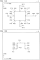
- Fig. 11A illustrates the pipe network projected onto the XY plane by parallel rays of light coming from the positive Z-axis direction.
- the pipes P32, P33, and P35 in Fig. 2 vanish in Fig. 11A , and hence the user cannot see these pipes. This is the case with the valve V37.
- the pipe P34 is not directly connected to the pipes P31 and P36.
- the pipes P31, P34, and P36 in Fig. 2 appear as a single pipe P99.
- the NWS device 1 models a pipe network which actually exists and runs various simulations on the pipe network. As the premise, the user of the NWS device 1 has to input three-dimensional coordinate values which represent positional information of each element to the NWS device 1.
- a skilled user uses a CAD device in the design of a pipe network to create three-dimensional coordinate values 101 of each element.
- These three-dimensional coordinate values include all of the X-axis coordinate value, the Y-axis coordinate value, and the Z-axis coordinate value of each element.
- the three-dimensional coordinate values of a pipe are a combination of the three-dimensional coordinate values of its upstream endpoint and the three-dimensional coordinate values of its downstream endpoint.
- the branch and the elbow are each an element which connects two or more pipes together. Taking this into consideration, the three-dimensional coordinate values of the branch or the elbow are the three-dimensional coordinate values of the connection point of these pipes. In this case, no problem arises if a skilled user operates the three-dimensional coordinate values and directly inputs the three-dimensional coordinate values to the NWS device 1.
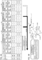
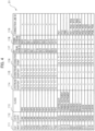
- Fig. 3A for example, the three-dimensional coordinate values of the upstream endpoint of the element P01 are written in the form of " (X, Y, Z) , " and the three-dimensional coordinate values of the downstream endpoint are also written in the form of " (X, Y, Z) . " This form does not mean that both the endpoints have the same coordinate values, but that the endpoints have different specific coordinate values in a representative manner. Needless to say, if two pipes branch from a point, the upstream endpoints of these two pipes have the same three-dimensional coordinate values. The same applies to Fig. 4 to Fig. 6 , too.
- the three-dimensional coordinate values are used being projected onto at least one of the XY plane, the YZ plane, and the XZ plane, i.e. by reducing the dimensionality by one.
- the NWS device 1 deletes the unnecessary Z-axis coordinate value from the three-dimensional coordinate values to create a coordinate value 103 projected onto the XY plane.
- a coordinate value 104 projected onto the YZ plane and a coordinate value 105 projected onto the XZ plane are examples of the XY plane.
- the NWS device 1 creates a diagram such as a perspective view or an isometric diagram.
- the NWS device 1 transforms the three-dimensional coordinate values 101 into coordinate values 102 projected onto any PQ plane.
- the NWS device 1 projects each element onto the PQ plane perpendicular to the line of sight, and acquires the coordinate values of the element on the PQ plane (see Fig. 3B ).
- the coordinate values 102 projected onto the PQ plane is data which has the P-axis coordinate value and the Q-axis coordinate value of each element.
- Each of the element IDs in the element ID section 111 is an identifier which uniquely identifies an element.
- the element ID of a pipe contains the letter "P. "
- element IDs of a compressor, a terminal instrument, a branch, an elbow, and a valve contain the letters “C,” “M, “ “B,” “E,” and “V,” respectively.
- the category in the category section 112 is either the "line” which means that the NWS device 1 deals with the element concerned as a line or the "node” which means that the NWS device 1 deals with the element concerned as a figure having an area.
- the upstream endpoint in the upstream endpoint section 114 indicates the three-dimensional coordinate values of the endpoint, among the two endpoints of a pipe, on the upstream side (the side nearer the compressor C12) where compressed air is incoming.
- the downstream node ID in the downstream node ID section 118 indicates the element ID of the node on the downstream side, among the two nodes at which the pipe concerned is connected.
- the upstream node ID and the downstream node ID are defined only for a line.
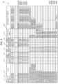
- Pipe network model information (#2) 32 is described along with Fig. 5 .
- the configuration of the sections (columns) of the pipe network model information (#2) 32 is only different from the pipe network model information (#1) 31 ( Fig. 4 ) in that instrument attributes are added to an instrument attribute section 120.
- the instrument attribute is an attribute of each element which is necessary to obtain simulation results for the pipe network.
- the NWS device 1 can obtain the following:
- the NWS device 1 Based on the above sets of information, the NWS device 1 outputs simulation results for each element.
- simulation results F(coordinate values of a given element, instrument attributes of the element, and analysis conditions of the element)."
- the NWS device inputs the variables “coordinate values of an element,” the variables “instrument attributes,” and the variables “analysis conditions,” and acquires variables “simulation results” outputted by the function "F.”
- function F has various known specific examples.
- step S1 the model information creation unit 21 of the NWS device 1 creates the pipe network model information.
- the model information creation unit 21 has completed creating the pipe network model information (#2) 32 ( Fig. 5 ) and stored the pipe network model information (#2) 32 in the auxiliary storage device 15 at the end of step S1.
- the simulation running unit 22 stores the pipe network model information (#2) 32 ( Fig. 5 ) with accepted analysis conditions in the auxiliary storage device 15.
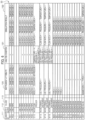
- the simulation running unit 22 creates the pipe network model information (#3) 33 ( Fig. 6 ) and stores the pipe network model information (#3) 33 in the auxiliary storage device 15 by use of the above described function F.
- the simulation running unit 22 displays the value of the pressure loss and the value of the flow rate corresponding to the selected element in a pressure loss section 311 and a flow rate section 312, respectively. Needless to say, the temperature or the pressure may be displayed.
- the simulation running unit 22 searches the simulation result section 122 of the pipe network model information (#3) 33 ( Fig. 6 ) with the selected evaluation item (e.g. "Pressure Loss") and evaluation threshold value as search keys.
- the simulation running unit 22 acquires the element IDs of the records whose numerical values of the selected evaluation item is equal to or more than the selected evaluation threshold value.
- the search condition here is that the numerical values are equal to or more than the evaluation threshold value, this is a mere example, of course. It suffices that the simulation running unit 22 acquires the element ID of a record based on the quantitative relationship between the numerical value and the evaluation threshold value of the evaluation item.
- the user may input the first plan view 41 with the X-axis coordinate value and the Y-axis coordinate value of each element by use of e.g. a keyboard.
- the data inputted at this stage is "first plane information.”
- the model information creation unit 21 acquires any element.
- the model information creation unit 21 accepts selection of any unprocessed element by the user (moving the cursor thereover) in the first plan view 41 ( Fig. 11A ).
- the model information creation unit 21 accepts a second plan view.
- the model information creation unit 21 accepts an input of the second plan view 42 ( Fig. 11B ) by the user through the input device 12 (scanner).
- the second plan view 42 is a projection of the imaginary element of the pipe network model acquired at step S203 onto, for example, the YZ plane.
- the model information creation unit 21 accepts an input of the numerical value of a length by the user into a length section 301.
- the model information creation unit 21 accepts selection of a string indicating the material by the user from the candidates in the pull-down menu displayed in the material section 303.
- the model information creation unit 21 updates the pipe network model information (#1) 31 ( Fig. 4 ). To be more specific, the model information creation unit 21 executes the following processes:
- the model information creation unit 21 judges whether or not there is an unprocessed element. To be more specific, the model information creation unit 21 returns to step S203 if there is an unprocessed element (step S212 "Yes") . If there is no unprocessed element (step S212 "No"), the processing procedures of creating the pipe network model information finish.
- the model information creation unit 21 accepts an input of the total length of the selected imaginary element, by the user into a pipe total length section 318.
- the total length of the imaginary element mentioned here is the length of the imaginary element P99.
- the user knows that the total length of the imaginary element P99 is the sum of the lengths of the elements P31 to P36. Hence, the user inputs the sum.
- the model information creation unit 21 accepts an input of the total number of elbows in the selected imaginary element, by the user into an elbow number section 319.
- the model information creation unit 21 accepts selection of the numerical value of a nominal diameter by the user from the candidates in the pull-down menu displayed in a diameter section 315.
- the input load on the user at steps S306 and S307 of the second example is greatly reduced compared to the first example.
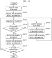
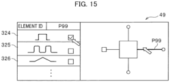
- the user has to input numerical values etc. in any case. Given the above, it is more advantageous if it is possible to completely omit the process of inputting numerical values etc. In the embodiment, the user has only to select the shape pattern of a pipe.
- Steps S201 to S205 and S210 to S212 are the same as those of the first example.
- the model information creation unit 21 accepts selection of one shape pattern by the user from the candidates. To be more specific, the user selects from these candidates a shape pattern similar to the shape of the imaginary element selected at step S203.
- the model information creation unit 21 updates the pipe network model information (#1) 31 ( Fig. 4 ). To be more specific, based on the accepted second plan view 42, the selected shape pattern, and the information associated with the shape pattern, the model information creation unit 21 updates the pipe network model information (#1) 31, and stores the pipe network model information (#1) 31 in the auxiliary storage device 15 as the pipe network model information (#2) 32 ( Fig. 5 ).
- the model information creation unit 21 can accept the XZ plan view as the second plan view 42. Moreover, the model information creation unit 21 can accept the YZ plan view as the second plan view and the XZ plan view as the third plan view if the double loop in the processing procedures of creating the pipe network model information is replaced with a triple loop.
- the total number of pipes which appear on the XY plan view 41 ( Fig. 11A ) is "12."
- These total numbers include the number of real elements and the number of imaginary elements.
- the model information creation unit 21 may determine as the "first plan view" one of the XZ plan view, the YZ plan view, and the XZ plan view with the largest apparent total number of pipes. After that, at step S201, the model information creation unit 21 may prompt the user to input the determined first plan view 41. This makes it possible to minimize the total processing time.
Landscapes
- Engineering & Computer Science (AREA)
- Physics & Mathematics (AREA)
- Geometry (AREA)
- Theoretical Computer Science (AREA)
- General Physics & Mathematics (AREA)
- Computer Hardware Design (AREA)
- General Engineering & Computer Science (AREA)
- Mathematical Analysis (AREA)
- Mathematical Optimization (AREA)
- Pure & Applied Mathematics (AREA)
- Evolutionary Computation (AREA)
- Computational Mathematics (AREA)
- Architecture (AREA)
- Structural Engineering (AREA)
- Civil Engineering (AREA)
- Computer Networks & Wireless Communication (AREA)
- Computer Graphics (AREA)
- Software Systems (AREA)
- Algebra (AREA)
- Computing Systems (AREA)
- Fluid Mechanics (AREA)
- Mathematical Physics (AREA)
- Human Computer Interaction (AREA)
- Management, Administration, Business Operations System, And Electronic Commerce (AREA)
- Processing Or Creating Images (AREA)
Claims (3)
- Netzsimulationsvorrichtung (1) zum Simulieren eines tatsächlich existierenden Rohrnetzes einer Fabrik durch striktes Abbilden des Layouts des Rohrnetzes in einem Rohrnetzmodell, um die Berechnungsgenauigkeit der Strömung von Druckluft durch das Rohrnetz zu verbessern, umfassend:eine Speichereinheit (15), die Netzmodellinformationen (31-33) speichert, die dreidimensionale Koordinatenwerte von jedem der Elemente speichern, die das Rohrnetz bilden, und die Musterinformationen speichert, die die Gesamtlänge des ausgewählten Elements und die Gesamtzahl der Instrumente in einem ausgewählten Element in Verbindung mit einem Formmuster von jedem einer Vielzahl der Elemente speichern; undeine Steuereinheit (21), die dazu ausgelegt ist,eine Eingabe von Informationen über eine erste Ebene zu akzeptieren, bei der es sich um Positionsinformationen über das Rohrnetz handelt, die auf eine Koordinatenebene projiziert werden, die zwei beliebige der drei Dimensionen als Koordinatenachsen hat,basierend auf den akzeptierten Informationen der ersten Ebene Netzmodellinformationen (31-33) zu erstellen, die einen Koordinatenwert der verbleibenden einen Dimension als unbekannt definieren,die Auswahl des Elements, dessen Koordinatenwert als unbekannt definiert ist, durch einen Benutzer aus den Elementen, die in der Information der ersten Ebene erscheinen, zu akzeptieren,eine Eingabe von Informationen über die zweite Ebene zu akzeptieren, die Positionsinformationen über das Rohrnetz sind, die auf eine Koordinatenebene mit zwei beliebigen Dimensionen, einschließlich der verbleibenden einen Dimension als Koordinatenachsen, projiziert werden,auf der Grundlage der akzeptierten Information der zweiten Ebene einen numerischen Wert, des als unbekannt definierten Koordinatenwertes des ausgewählten Elementes in den erstellten Netzmodellinformationen (31-33) zu bestimmen,eine Eingabe eines Attributs des Elements durch den Benutzer zu akzeptieren,eine Eingabe eines Betriebswerts des gegebenen Elements durch den Benutzer zu akzeptieren,auf der Grundlage des akzeptierten Attributs, des akzeptierten Betriebswertes und der Netzmodellinformationen (31-33) für jedes Element ein Ergebnis der Simulation eines numerischen Wertes auszugeben, der einen Kennwert des Rohrnetzes angibt,eine Eingabe einer Gesamtlänge des ausgewählten Elements und einer Gesamtzahl von Instrumenten in dem ausgewählten Element durch den Benutzer zu akzeptieren, während eine Eingabe der Information der zweiten Ebene akzeptiert wird,die Auswahl des dem ausgewählten Element entsprechenden Formmusters durch den Benutzer zu akzeptieren, wobei die Gesamtlänge des ausgewählten Elements und die Gesamtzahl der Instrumente in dem ausgewählten Element akzeptiert werden,die Gesamtlänge des ausgewählten Elements und die Gesamtzahl der Instrumente in dem ausgewählten Element entsprechend dem ausgewählten Formmuster zu erfassen,eine Eingabe der Information der ersten Ebene und der Information der zweiten Ebene als Bilddaten zu akzeptieren,als die Information der ersten Ebene die Koordinatenebene mit der größten Gesamtzahl der Elemente zu bestimmen, die bei der Projektion des Rohrnetzes erscheinen,die Eingabe eines Schwellenwertes durch den Benutzer für den numerischen Wert zu akzeptieren, der den Kennwert angibt,auf der Grundlage einer quantitativen Beziehung zwischen dem numerischen Wert, der den Kennwert angibt, und dem akzeptierten Schwellenwert das Element in einem abnormen Zustand zu identifizieren, unddas identifizierte Element hervorzuheben,wobeidas Rohrnetz Druckluft liefert,das Attribut und der Betriebswert keinen Wert für die Strömungsrate enthalten, undder Kennwert die Strömungsrate und einen Druckverlust enthält, so dass der Benutzer feststellen kann, wie viel Druck in dem tatsächlich vorhandenen Rohrnetz möglicherweise verloren geht, und Maßnahmen zur Vermeidung des Druckverlusts ergreifen kann.
- Verfahren zur Verwendung einer Netzsimulationsvorrichtung (1) zum Simulieren eines tatsächlich existierenden Rohrnetzes einer Fabrik durch striktes Abbilden des Layouts des Rohrnetzes in einem Rohrnetzmodell, um die Berechnungsgenauigkeit der Strömung von Druckluft durch das Rohrnetz zu verbessern, in dem:bewirkt wird, dass eine Speichereinheit (15) der Netzsimulationsvorrichtung (1) Netzmodellinformationen (31-33) speichert, die dreidimensionale Koordinatenwerte von jedem der Elemente, die das Rohrnetz bilden, speichern, und dass Musterinformationen gespeichert werden, die die Gesamtlänge des ausgewählten Elements und die Gesamtzahl der Instrumente in einem ausgewählten Element in Verbindung mit einem Formmuster von jedem einer Vielzahl der Elemente speichern; undeine Steuereinheit (21) der Netzsimulationsvorrichtung (1) veranlasst wird,eine Eingabe von Informationen über eine erste Ebene zu akzeptieren, bei der es sich um Positionsinformationen über das Rohrnetz handelt, die auf eine Koordinatenebene projiziert werden, die zwei beliebige der drei Dimensionen als Koordinatenachsen hat,die Netzmodellinformationen (31-33) zu erstellen, die auf der Grundlage der akzeptierten Informationen der ersten Ebene einen Koordinatenwert der verbleibenden einen Dimension als unbekannt definieren,aus den Elementen, die in der Information der ersten Ebene erscheinen, die Auswahl des Elements zu akzeptieren, dessen Koordinatenwert von einem Benutzer als unbekannt definiert wurde,eine Eingabe von Informationen über eine zweite Ebene zu akzeptieren, die Positionsinformationen über das Rohrnetz sind, die auf eine Koordinatenebene projiziert werden, die zwei beliebige Dimensionen einschließlich der verbleibenden einen Dimension als Koordinatenachsen hat, undauf der Grundlage der akzeptierten Information der zweiten Ebene einen numerischen Wert des als unbekannt definierten Koordinatenwertes des ausgewählten Elementes in den erstellten Netzmodellinformationen (31-33) zu bestimmen,eine Eingabe eines Attributs des Elements durch den Benutzer zu akzeptieren,eine Eingabe eines Betriebswerts des gegebenen Elements durch den Benutzer akzeptieren,auf der Grundlage des akzeptierten Attributs, des akzeptierten Betriebswertes und der Netzmodellinformationen (31-33) für jedes Element ein Ergebnis der Simulation eines numerischen Wertes auszugeben, der einen Kennwert des Rohrnetzes angibt,eine Eingabe einer Gesamtlänge des ausgewählten Elements und einer Gesamtzahl von Instrumenten in dem ausgewählten Element durch den Benutzer zu akzeptieren, während eine Eingabe der Information der zweiten Ebene akzeptiert wird,die Auswahl des dem ausgewählten Element entsprechenden Formmusters durch den Benutzer zu akzeptieren, wobei die Gesamtlänge des ausgewählten Elements und die Gesamtzahl der Instrumente in dem ausgewählten Element akzeptiert werden,die Gesamtlänge des ausgewählten Elements und die Gesamtzahl der Instrumente in dem ausgewählten Element entsprechend dem ausgewählten Formmuster zu erfassen,eine Eingabe der Information der ersten Ebene und der Information der zweiten Ebene als Bilddaten zu akzeptieren,als Information der ersten Ebene die Koordinatenebene mit der größten Gesamtzahl der Elemente zu bestimmen, die bei der Projektion des Rohrnetzes erscheinen,die Eingabe eines Schwellenwertes durch den Benutzer für den numerischen Wert zu akzeptieren, der den Kennwert angibt,auf der Grundlage einer quantitativen Beziehung zwischen dem numerischen Wert, der den Kennwert angibt, und dem akzeptierten Schwellenwert das Element in einem abnormen Zustand zu identifizieren, unddas identifizierte Element hervorzuheben,wobeidas Rohrnetz Druckluft liefert,das Attribut und der Betriebswert keinen Wert für die Strömungsrate enthalten, undder Kennwert die Strömungsrate und einen Druckverlust enthält, so dass der Benutzer feststellen kann, wie viel Druck in dem tatsächlich vorhandenen Rohrnetz möglicherweise verloren geht, und Maßnahmen zur Vermeidung des Druckverlusts ergreifen kann.
- Netzsimulationsprogramm zur Simulation eines Rohrnetzes, das eine Netzsimulationsvorrichtung (1) veranlasst, alle in dem Verfahren nach Anspruch 2 definierten Schritte auszuführen.
Applications Claiming Priority (2)
| Application Number | Priority Date | Filing Date | Title |
|---|---|---|---|
| JP2015042311A JP6429682B2 (ja) | 2015-03-04 | 2015-03-04 | ネットワークシミュレーション装置、ネットワークシミュレーション方法及びネットワークシミュレーションプログラム |
| PCT/JP2016/051368 WO2016139979A1 (ja) | 2015-03-04 | 2016-01-19 | ネットワークシミュレーション装置、ネットワークシミュレーション方法及びネットワークシミュレーションプログラム |
Publications (3)
| Publication Number | Publication Date |
|---|---|
| EP3267340A1 EP3267340A1 (de) | 2018-01-10 |
| EP3267340A4 EP3267340A4 (de) | 2018-11-21 |
| EP3267340B1 true EP3267340B1 (de) | 2025-07-09 |
Family
ID=56845322
Family Applications (1)
| Application Number | Title | Priority Date | Filing Date |
|---|---|---|---|
| EP16758675.9A Active EP3267340B1 (de) | 2015-03-04 | 2016-01-19 | Netzwerksimulationsvorrichtung, netzwerksimulationsverfahren sowie netzwerksimulationsprogramm |
Country Status (5)
| Country | Link |
|---|---|
| US (1) | US10885237B2 (de) |
| EP (1) | EP3267340B1 (de) |
| JP (1) | JP6429682B2 (de) |
| CN (1) | CN107408141B (de) |
| WO (1) | WO2016139979A1 (de) |
Families Citing this family (10)
| Publication number | Priority date | Publication date | Assignee | Title |
|---|---|---|---|---|
| EP3690575B1 (de) * | 2019-02-04 | 2022-08-24 | Siemens Aktiengesellschaft | Verfahren zur überprüfung einer konsistenten erfassung von rohrleitungen in einem projektierungssystem, projektierungssystem und steuerungsprogramm |
| WO2020183647A1 (ja) * | 2019-03-13 | 2020-09-17 | 三菱電機株式会社 | シミュレーション装置、シミュレーションプログラム及びシミュレーション方法 |
| CN112463467B (zh) * | 2019-09-09 | 2022-03-22 | 英业达科技有限公司 | 自动化的整合测试系统及其方法 |
| CN110990982A (zh) * | 2019-11-15 | 2020-04-10 | 深圳航天智慧城市系统技术研究院有限公司 | 一种基于Skyline的将二维管线三维化的方法 |
| JP7291637B2 (ja) | 2020-01-06 | 2023-06-15 | 株式会社日立産機システム | 圧縮機制御装置の設定値決定支援装置及び設定値決定支援方法、並びに圧縮機運転制御システム |
| CN113515826B (zh) * | 2021-04-09 | 2022-11-25 | 云南电网有限责任公司昆明供电局 | 配电网合环线路拓扑搜索方法及系统 |
| WO2022254731A1 (ja) * | 2021-06-04 | 2022-12-08 | NatureArchitects株式会社 | 構造体の設計探索装置および設計探索方法 |
| CN115618531A (zh) * | 2021-07-12 | 2023-01-17 | 广东博智林机器人有限公司 | 管网中管线的处理方法、装置、计算机设备和存储介质 |
| WO2024238834A1 (en) * | 2023-05-16 | 2024-11-21 | Fracta, Inc. | Methods of imputing attribute information for infrastructure elements |
| CN117216836B (zh) * | 2023-08-24 | 2024-05-07 | 中国电建集团成都勘测设计研究院有限公司 | 一种基于Dynamo的闸门设备批量建模方法 |
Family Cites Families (21)
| Publication number | Priority date | Publication date | Assignee | Title |
|---|---|---|---|---|
| US4181954A (en) | 1971-05-19 | 1980-01-01 | Chevron Research Company | Computer-aided graphics system including a computerized material control system and method of using same |
| JP2695657B2 (ja) * | 1989-03-29 | 1998-01-14 | 三菱重工業株式会社 | 配管寸法線図作成装置 |
| LTIP1892A (en) | 1993-06-15 | 1994-12-27 | Combustion Eng | Corrosian analysis system and method |
| JPH07262407A (ja) * | 1994-03-18 | 1995-10-13 | Sanyo Electric Co Ltd | 2次元図面から3次元データを生成する方法 |
| US6016147A (en) | 1995-05-08 | 2000-01-18 | Autodesk, Inc. | Method and system for interactively determining and displaying geometric relationships between three dimensional objects based on predetermined geometric constraints and position of an input device |
| US7246044B2 (en) * | 2000-09-13 | 2007-07-17 | Matsushita Electric Works, Ltd. | Method for aiding space design using network, system therefor, and server computer of the system |
| US20040136590A1 (en) * | 2002-09-20 | 2004-07-15 | Albert-Jan Brouwer | Means of partitioned matching and selective refinement in a render, match, and refine iterative 3D scene model refinement system through propagation of model element identifiers |
| US7698110B2 (en) * | 2005-10-13 | 2010-04-13 | Autodesk, Inc. | Method for dynamically generating multiple views of three-dimensional models for utility networks |
| JP2009042811A (ja) * | 2007-08-06 | 2009-02-26 | Univ Of Tokyo | 3次元形状展開装置、3次元形状展開方法、および3次元形状展開用プログラム |
| CN101364242B (zh) * | 2007-08-10 | 2011-09-14 | 上海精力信息科技有限公司 | 三维可视化非开挖地下管道gis建立方法 |
| JP4804501B2 (ja) * | 2008-04-16 | 2011-11-02 | 関東自動車工業株式会社 | ワイヤハーネスの配索形状表示装置 |
| JP5195641B2 (ja) * | 2009-05-26 | 2013-05-08 | 富士通株式会社 | ハーネス検証装置およびハーネス検証プログラム |
| US8386221B2 (en) * | 2009-12-07 | 2013-02-26 | Nuovo Pignone S.P.A. | Method for subsea equipment subject to hydrogen induced stress cracking |
| JP5021790B2 (ja) | 2010-05-28 | 2012-09-12 | 新菱冷熱工業株式会社 | Cad装置 |
| US20120013483A1 (en) * | 2010-07-17 | 2012-01-19 | Jung Sungeun | Water Supply Maintenance System |
| CN102201128A (zh) * | 2011-04-14 | 2011-09-28 | 北京怡诚科训技术发展有限公司 | 管道模型的转换方法及装置 |
| US9026415B2 (en) * | 2011-10-20 | 2015-05-05 | Energy Solutions International, Inc. | Pipeline flow modeling method |
| EP2986962A1 (de) * | 2013-04-19 | 2016-02-24 | Gutermann AG | Verfahren zur bewertung akustischer sensordaten in einem flüssigkeitsführenden netzwerk und bewertungseinheit |
| CN103488838B (zh) * | 2013-09-27 | 2016-08-17 | 无锡华光锅炉股份有限公司 | 一种余热锅炉管道计算机辅助出图方法 |
| CN104155659B (zh) * | 2014-08-22 | 2017-02-15 | 广州特种承压设备检测研究院 | 一种压力管道的单线图测绘系统及方法 |
| CN104318026A (zh) * | 2014-10-29 | 2015-01-28 | 青岛鸿瑞电力工程咨询有限公司 | 管道设计一体化自动生成方法 |
-
2015
- 2015-03-04 JP JP2015042311A patent/JP6429682B2/ja active Active
-
2016
- 2016-01-19 US US15/555,427 patent/US10885237B2/en active Active
- 2016-01-19 EP EP16758675.9A patent/EP3267340B1/de active Active
- 2016-01-19 WO PCT/JP2016/051368 patent/WO2016139979A1/ja not_active Ceased
- 2016-01-19 CN CN201680012876.5A patent/CN107408141B/zh active Active
Also Published As
| Publication number | Publication date |
|---|---|
| JP2016162343A (ja) | 2016-09-05 |
| CN107408141A (zh) | 2017-11-28 |
| JP6429682B2 (ja) | 2018-11-28 |
| WO2016139979A1 (ja) | 2016-09-09 |
| EP3267340A1 (de) | 2018-01-10 |
| CN107408141B (zh) | 2020-12-04 |
| US20180039719A1 (en) | 2018-02-08 |
| US10885237B2 (en) | 2021-01-05 |
| EP3267340A4 (de) | 2018-11-21 |
Similar Documents
| Publication | Publication Date | Title |
|---|---|---|
| EP3267340B1 (de) | Netzwerksimulationsvorrichtung, netzwerksimulationsverfahren sowie netzwerksimulationsprogramm | |
| KR101794282B1 (ko) | 2차원 배관 캐드 데이터에서 3차원 배관 캐드 모델링 데이터를 생성하는 방법 | |
| EP2178013A2 (de) | Vorrichtung zur Erzeugung dreidimensionaler Daten, zugehöriges Verfahren und Programm | |
| US9158866B2 (en) | Layout-design support system and layout-design support program | |
| Raizer | Theory of reliability in structural design | |
| KR20140015812A (ko) | 1차원 수질모델 입력자료 생성지원을 위한 gis기반의 모식도 자동작성 시스템 및 모식도 작성 방법 | |
| US20070288207A1 (en) | Displaying characteristics of a system of interconnected components at different system locations | |
| CN114896477A (zh) | 一种支持多种语言算法的数据挖掘安全可视化系统及方法 | |
| US7644363B2 (en) | “For-each” label components in CAD drawings | |
| JP4738067B2 (ja) | Cadデータ作成装置および方法 | |
| Kim et al. | Automated and qualitative structural evaluation of floor plans for remodeling of apartment housing | |
| CN114707196B (zh) | 航天器平台可视化的设计方法、装置、电子设备及介质 | |
| CN115587793A (zh) | 基于建筑信息模型的工程监管方法、系统、设备及介质 | |
| JP2009222132A (ja) | 保守点検支援プログラム、保守点検支援装置および保守点検支援方法 | |
| CN105095599A (zh) | 一种dwg格式图纸自动生成方法 | |
| US7424413B2 (en) | Method for optimizing turbine engine exhaust system | |
| CN112182886A (zh) | 工程模型生成方法、装置、计算机设备和存储介质 | |
| JP2019075062A (ja) | 設計支援装置および設計支援方法 | |
| JP4861125B2 (ja) | レイアウト設計支援システムと方法、およびプログラム | |
| KR20230162056A (ko) | 건축물 또는 토목 구조물의 관리 지원 시스템 | |
| CN115796805A (zh) | 一种机电安装项目的算量方法、装置及存储介质 | |
| CN104200035A (zh) | 电气辅助设计方法及系统 | |
| CN116309934B (zh) | 一种基于图元预测的图纸绘制方法、装置、电子设备及存储介质 | |
| CN103984784A (zh) | 核电站图模一体可视化方法及系统 | |
| US8769460B1 (en) | Device recognition engine |
Legal Events
| Date | Code | Title | Description |
|---|---|---|---|
| STAA | Information on the status of an ep patent application or granted ep patent |
Free format text: STATUS: THE INTERNATIONAL PUBLICATION HAS BEEN MADE |
|
| PUAI | Public reference made under article 153(3) epc to a published international application that has entered the european phase |
Free format text: ORIGINAL CODE: 0009012 |
|
| STAA | Information on the status of an ep patent application or granted ep patent |
Free format text: STATUS: REQUEST FOR EXAMINATION WAS MADE |
|
| 17P | Request for examination filed |
Effective date: 20170922 |
|
| AK | Designated contracting states |
Kind code of ref document: A1 Designated state(s): AL AT BE BG CH CY CZ DE DK EE ES FI FR GB GR HR HU IE IS IT LI LT LU LV MC MK MT NL NO PL PT RO RS SE SI SK SM TR |
|
| AX | Request for extension of the european patent |
Extension state: BA ME |
|
| DAV | Request for validation of the european patent (deleted) | ||
| DAX | Request for extension of the european patent (deleted) | ||
| A4 | Supplementary search report drawn up and despatched |
Effective date: 20181022 |
|
| RIC1 | Information provided on ipc code assigned before grant |
Ipc: G06F 17/50 20060101AFI20181016BHEP |
|
| STAA | Information on the status of an ep patent application or granted ep patent |
Free format text: STATUS: EXAMINATION IS IN PROGRESS |
|
| 17Q | First examination report despatched |
Effective date: 20220221 |
|
| REG | Reference to a national code |
Ref country code: DE Ref legal event code: R079 Free format text: PREVIOUS MAIN CLASS: G06F0017500000 Ipc: G06F0030120000 Ref country code: DE Ref legal event code: R079 Ref document number: 602016092835 Country of ref document: DE Free format text: PREVIOUS MAIN CLASS: G06F0017500000 Ipc: G06F0030120000 |
|
| GRAP | Despatch of communication of intention to grant a patent |
Free format text: ORIGINAL CODE: EPIDOSNIGR1 |
|
| STAA | Information on the status of an ep patent application or granted ep patent |
Free format text: STATUS: GRANT OF PATENT IS INTENDED |
|
| RIC1 | Information provided on ipc code assigned before grant |
Ipc: G06F 113/14 20200101ALN20250220BHEP Ipc: G06F 30/18 20200101ALI20250220BHEP Ipc: G06F 30/13 20200101ALI20250220BHEP Ipc: G06F 30/28 20200101ALI20250220BHEP Ipc: G06F 30/12 20200101AFI20250220BHEP |
|
| INTG | Intention to grant announced |
Effective date: 20250310 |
|
| GRAS | Grant fee paid |
Free format text: ORIGINAL CODE: EPIDOSNIGR3 |
|
| GRAA | (expected) grant |
Free format text: ORIGINAL CODE: 0009210 |
|
| STAA | Information on the status of an ep patent application or granted ep patent |
Free format text: STATUS: THE PATENT HAS BEEN GRANTED |
|
| AK | Designated contracting states |
Kind code of ref document: B1 Designated state(s): AL AT BE BG CH CY CZ DE DK EE ES FI FR GB GR HR HU IE IS IT LI LT LU LV MC MK MT NL NO PL PT RO RS SE SI SK SM TR |
|
| REG | Reference to a national code |
Ref country code: GB Ref legal event code: FG4D |
|
| REG | Reference to a national code |
Ref country code: CH Ref legal event code: EP |
|
| REG | Reference to a national code |
Ref country code: IE Ref legal event code: FG4D |
|
| REG | Reference to a national code |
Ref country code: DE Ref legal event code: R096 Ref document number: 602016092835 Country of ref document: DE |
|
| RAP4 | Party data changed (patent owner data changed or rights of a patent transferred) |
Owner name: HITACHI INDUSTRIAL EQUIPMENT SYSTEMS CO., LTD. |
|
| REG | Reference to a national code |
Ref country code: NL Ref legal event code: MP Effective date: 20250709 |
|
| PG25 | Lapsed in a contracting state [announced via postgrant information from national office to epo] |
Ref country code: PT Free format text: LAPSE BECAUSE OF FAILURE TO SUBMIT A TRANSLATION OF THE DESCRIPTION OR TO PAY THE FEE WITHIN THE PRESCRIBED TIME-LIMIT Effective date: 20251110 |
|
| PG25 | Lapsed in a contracting state [announced via postgrant information from national office to epo] |
Ref country code: NL Free format text: LAPSE BECAUSE OF FAILURE TO SUBMIT A TRANSLATION OF THE DESCRIPTION OR TO PAY THE FEE WITHIN THE PRESCRIBED TIME-LIMIT Effective date: 20250709 |
|
| REG | Reference to a national code |
Ref country code: AT Ref legal event code: MK05 Ref document number: 1812516 Country of ref document: AT Kind code of ref document: T Effective date: 20250709 |
|
| PG25 | Lapsed in a contracting state [announced via postgrant information from national office to epo] |
Ref country code: IS Free format text: LAPSE BECAUSE OF FAILURE TO SUBMIT A TRANSLATION OF THE DESCRIPTION OR TO PAY THE FEE WITHIN THE PRESCRIBED TIME-LIMIT Effective date: 20251109 |
|
| PG25 | Lapsed in a contracting state [announced via postgrant information from national office to epo] |
Ref country code: NO Free format text: LAPSE BECAUSE OF FAILURE TO SUBMIT A TRANSLATION OF THE DESCRIPTION OR TO PAY THE FEE WITHIN THE PRESCRIBED TIME-LIMIT Effective date: 20251009 |
|
| REG | Reference to a national code |
Ref country code: LT Ref legal event code: MG9D |
|
| PG25 | Lapsed in a contracting state [announced via postgrant information from national office to epo] |
Ref country code: AT Free format text: LAPSE BECAUSE OF FAILURE TO SUBMIT A TRANSLATION OF THE DESCRIPTION OR TO PAY THE FEE WITHIN THE PRESCRIBED TIME-LIMIT Effective date: 20250709 |
|
| PG25 | Lapsed in a contracting state [announced via postgrant information from national office to epo] |
Ref country code: FI Free format text: LAPSE BECAUSE OF FAILURE TO SUBMIT A TRANSLATION OF THE DESCRIPTION OR TO PAY THE FEE WITHIN THE PRESCRIBED TIME-LIMIT Effective date: 20250709 |
|
| PG25 | Lapsed in a contracting state [announced via postgrant information from national office to epo] |
Ref country code: HR Free format text: LAPSE BECAUSE OF FAILURE TO SUBMIT A TRANSLATION OF THE DESCRIPTION OR TO PAY THE FEE WITHIN THE PRESCRIBED TIME-LIMIT Effective date: 20250709 |
|
| PG25 | Lapsed in a contracting state [announced via postgrant information from national office to epo] |
Ref country code: GR Free format text: LAPSE BECAUSE OF FAILURE TO SUBMIT A TRANSLATION OF THE DESCRIPTION OR TO PAY THE FEE WITHIN THE PRESCRIBED TIME-LIMIT Effective date: 20251010 |
|
| PG25 | Lapsed in a contracting state [announced via postgrant information from national office to epo] |
Ref country code: SE Free format text: LAPSE BECAUSE OF FAILURE TO SUBMIT A TRANSLATION OF THE DESCRIPTION OR TO PAY THE FEE WITHIN THE PRESCRIBED TIME-LIMIT Effective date: 20250709 |
|
| PG25 | Lapsed in a contracting state [announced via postgrant information from national office to epo] |
Ref country code: LV Free format text: LAPSE BECAUSE OF FAILURE TO SUBMIT A TRANSLATION OF THE DESCRIPTION OR TO PAY THE FEE WITHIN THE PRESCRIBED TIME-LIMIT Effective date: 20250709 |
|
| PG25 | Lapsed in a contracting state [announced via postgrant information from national office to epo] |
Ref country code: BG Free format text: LAPSE BECAUSE OF FAILURE TO SUBMIT A TRANSLATION OF THE DESCRIPTION OR TO PAY THE FEE WITHIN THE PRESCRIBED TIME-LIMIT Effective date: 20250709 Ref country code: PL Free format text: LAPSE BECAUSE OF FAILURE TO SUBMIT A TRANSLATION OF THE DESCRIPTION OR TO PAY THE FEE WITHIN THE PRESCRIBED TIME-LIMIT Effective date: 20250709 |
|
| PG25 | Lapsed in a contracting state [announced via postgrant information from national office to epo] |
Ref country code: RS Free format text: LAPSE BECAUSE OF FAILURE TO SUBMIT A TRANSLATION OF THE DESCRIPTION OR TO PAY THE FEE WITHIN THE PRESCRIBED TIME-LIMIT Effective date: 20251009 |
|
| PG25 | Lapsed in a contracting state [announced via postgrant information from national office to epo] |
Ref country code: ES Free format text: LAPSE BECAUSE OF FAILURE TO SUBMIT A TRANSLATION OF THE DESCRIPTION OR TO PAY THE FEE WITHIN THE PRESCRIBED TIME-LIMIT Effective date: 20250709 |
|
| PG25 | Lapsed in a contracting state [announced via postgrant information from national office to epo] |
Ref country code: SM Free format text: LAPSE BECAUSE OF FAILURE TO SUBMIT A TRANSLATION OF THE DESCRIPTION OR TO PAY THE FEE WITHIN THE PRESCRIBED TIME-LIMIT Effective date: 20250709 |
|
| PGFP | Annual fee paid to national office [announced via postgrant information from national office to epo] |
Ref country code: GB Payment date: 20260119 Year of fee payment: 11 |
|
| PG25 | Lapsed in a contracting state [announced via postgrant information from national office to epo] |
Ref country code: DK Free format text: LAPSE BECAUSE OF FAILURE TO SUBMIT A TRANSLATION OF THE DESCRIPTION OR TO PAY THE FEE WITHIN THE PRESCRIBED TIME-LIMIT Effective date: 20250709 |
|
| PGFP | Annual fee paid to national office [announced via postgrant information from national office to epo] |
Ref country code: DE Payment date: 20260126 Year of fee payment: 11 |
|
| PG25 | Lapsed in a contracting state [announced via postgrant information from national office to epo] |
Ref country code: IT Free format text: LAPSE BECAUSE OF FAILURE TO SUBMIT A TRANSLATION OF THE DESCRIPTION OR TO PAY THE FEE WITHIN THE PRESCRIBED TIME-LIMIT Effective date: 20250709 |
|
| PGFP | Annual fee paid to national office [announced via postgrant information from national office to epo] |
Ref country code: BE Payment date: 20260121 Year of fee payment: 11 |
|
| PGFP | Annual fee paid to national office [announced via postgrant information from national office to epo] |
Ref country code: FR Payment date: 20260223 Year of fee payment: 11 |
|
| PG25 | Lapsed in a contracting state [announced via postgrant information from national office to epo] |
Ref country code: CZ Free format text: LAPSE BECAUSE OF FAILURE TO SUBMIT A TRANSLATION OF THE DESCRIPTION OR TO PAY THE FEE WITHIN THE PRESCRIBED TIME-LIMIT Effective date: 20250709 |
|
| PG25 | Lapsed in a contracting state [announced via postgrant information from national office to epo] |
Ref country code: SK Free format text: LAPSE BECAUSE OF FAILURE TO SUBMIT A TRANSLATION OF THE DESCRIPTION OR TO PAY THE FEE WITHIN THE PRESCRIBED TIME-LIMIT Effective date: 20250709 Ref country code: EE Free format text: LAPSE BECAUSE OF FAILURE TO SUBMIT A TRANSLATION OF THE DESCRIPTION OR TO PAY THE FEE WITHIN THE PRESCRIBED TIME-LIMIT Effective date: 20250709 |