EP3267317A1 - Portable device with vibration sensor - Google Patents
Portable device with vibration sensor Download PDFInfo
- Publication number
- EP3267317A1 EP3267317A1 EP17178954.8A EP17178954A EP3267317A1 EP 3267317 A1 EP3267317 A1 EP 3267317A1 EP 17178954 A EP17178954 A EP 17178954A EP 3267317 A1 EP3267317 A1 EP 3267317A1
- Authority
- EP
- European Patent Office
- Prior art keywords
- vibration sensor
- portable device
- controller
- communication
- defective
- Prior art date
- Legal status (The legal status is an assumption and is not a legal conclusion. Google has not performed a legal analysis and makes no representation as to the accuracy of the status listed.)
- Granted
Links
Images
Classifications
-
- G—PHYSICS
- G06—COMPUTING OR CALCULATING; COUNTING
- G06F—ELECTRIC DIGITAL DATA PROCESSING
- G06F11/00—Error detection; Error correction; Monitoring
- G06F11/07—Responding to the occurrence of a fault, e.g. fault tolerance
- G06F11/0703—Error or fault processing not based on redundancy, i.e. by taking additional measures to deal with the error or fault not making use of redundancy in operation, in hardware, or in data representation
- G06F11/0751—Error or fault detection not based on redundancy
-
- G—PHYSICS
- G06—COMPUTING OR CALCULATING; COUNTING
- G06F—ELECTRIC DIGITAL DATA PROCESSING
- G06F1/00—Details not covered by groups G06F3/00 - G06F13/00 and G06F21/00
- G06F1/16—Constructional details or arrangements
- G06F1/1613—Constructional details or arrangements for portable computers
- G06F1/1633—Constructional details or arrangements of portable computers not specific to the type of enclosures covered by groups G06F1/1615 - G06F1/1626
- G06F1/1684—Constructional details or arrangements related to integrated I/O peripherals not covered by groups G06F1/1635 - G06F1/1675
-
- G—PHYSICS
- G06—COMPUTING OR CALCULATING; COUNTING
- G06F—ELECTRIC DIGITAL DATA PROCESSING
- G06F11/00—Error detection; Error correction; Monitoring
- G06F11/07—Responding to the occurrence of a fault, e.g. fault tolerance
- G06F11/0703—Error or fault processing not based on redundancy, i.e. by taking additional measures to deal with the error or fault not making use of redundancy in operation, in hardware, or in data representation
- G06F11/0706—Error or fault processing not based on redundancy, i.e. by taking additional measures to deal with the error or fault not making use of redundancy in operation, in hardware, or in data representation the processing taking place on a specific hardware platform or in a specific software environment
- G06F11/0736—Error or fault processing not based on redundancy, i.e. by taking additional measures to deal with the error or fault not making use of redundancy in operation, in hardware, or in data representation the processing taking place on a specific hardware platform or in a specific software environment in functional embedded systems, i.e. in a data processing system designed as a combination of hardware and software dedicated to performing a certain function
- G06F11/0742—Error or fault processing not based on redundancy, i.e. by taking additional measures to deal with the error or fault not making use of redundancy in operation, in hardware, or in data representation the processing taking place on a specific hardware platform or in a specific software environment in functional embedded systems, i.e. in a data processing system designed as a combination of hardware and software dedicated to performing a certain function in a data processing system embedded in a mobile device, e.g. mobile phones, handheld devices
-
- G—PHYSICS
- G06—COMPUTING OR CALCULATING; COUNTING
- G06F—ELECTRIC DIGITAL DATA PROCESSING
- G06F13/00—Interconnection of, or transfer of information or other signals between, memories, input/output devices or central processing units
- G06F13/38—Information transfer, e.g. on bus
- G06F13/42—Bus transfer protocol, e.g. handshake; Synchronisation
- G06F13/4282—Bus transfer protocol, e.g. handshake; Synchronisation on a serial bus, e.g. I2C bus, SPI bus
Definitions
- the present invention relates to a portable device that includes a vibration sensor.
- Japanese Laid-Open Patent Publication No. 2013-37632 discloses a portable device that incorporates a vibration sensor.
- the vibration sensor detects vibration of the portable device
- the vibration sensor provides an interruption signal to a CPU of the portable device.
- the interruption signal is received from the vibration sensor, the CPU shifts the state of the portable device to a communication ready state that allows for bidirectional communication between the portable device and a vehicle.
- the portable device is used in SMART KEY SYSTEM (registered trademark) in which the portable device performs wireless communication with a communication peer device, which may be a vehicle.
- SMART KEY SYSTEM registered trademark
- the portable device performs wireless communication with a communication peer device, which may be a vehicle.
- the CPU receives an interruption signal from the vibration sensor
- the portable device is shifted to the communication ready state, which allows the portable device to receive LF signals from the communication peer device.
- the portable device receives an LF signal from the communication peer device in the communication ready state
- the portable device transmits an RF signal in response. Consequently, smart communication is established between the vehicle and the portable device.
- SMART KEY SYSTEM when the portable device is validated by key verification performed through the smart communication, the portable device or the user carrying the portable device is allowed to control the vehicle.
- Detection of vibration initiates an interruption process for realizing a specific function of the portable device.
- the vibration sensor has a defect, which may be mechanical and/or electrical malfunction, and the interruption process cannot be performed, the portable device may not be shifted to the communication ready state, which would allow for the smart communication.
- the remote keyless entry button of the portable device is pressed, the vehicle can be controlled by the portable device through unidirectional communication.
- the usability of the portable device would decrease when such a defective vibration sensor limits the portable device to unidirectional communication as compared to a portable device that includes a normally functioning vibration sensor and is capable of controlling the vehicle through the smart communication.
- One aspect of the present invention is a portable device that includes a vibration sensor.
- the portable device includes a controller that checks a status of the vibration sensor. When the controller determines that the vibration sensor is defective, the controller disconnects the vibration sensor and operates the portable device.
- the controller determines that the vibration sensor is defective, the controller disconnects the defective vibration sensor so that behaviors of the defective vibration sensor do not affect the controller.
- a specific function of the portable device is executed by an interruption from the vibration sensor.
- the specific function of the portable device is executed even when the vibration sensor is defective.
- the failsafe capability of the portable device is increased. This prevents or minimizes decreases in the usability of the portable device that would be caused by a defective vibration sensor.
- the controller is configured to periodically check the status of the vibration sensor in compliance with a synchronous serial communication protocol of a SPI specification or I 2 C specification.
- the communication speed is increased as compared to asynchronous serial communication (e.g., RS-232C serial communication).
- asynchronous serial communication e.g., RS-232C serial communication
- the controller is configured to invalidate an input from the vibration sensor when the controller determines that the vibration sensor is defective.
- the controller determines that the vibration sensor is defective, the controller disregards signals provided from the vibration sensor. This allows the controller to execute the specific function while disconnecting the defective vibration sensor in terms of electric signals or functions.
- the portable device further includes a wireless signal receiver configured to receive a wireless signal from a communication peer device.
- the vibration sensor is configured to provide an interruption signal to the controller when the vibration sensor detects vibration of the portable device.
- the controller is configured to execute a specific function of the portable device when provided with the interruption signal from the vibration sensor.
- the specific function of the portable device includes a communication standby function that has the wireless signal receiver wait to receive the wireless signal.
- the controller is configured to activate the specific function of the portable device when the controller detects that the vibration sensor is defective regardless of whether or not the interruption signal is provided from the vibration sensor.
- This configuration allows for execution of the function to receive wireless signals even when the vibration sensor is defective. This prevents or minimizes decreases in the usability of the portable device that would be caused by a defective vibration sensor.
- the portable device further includes a notifying means that is actuated to issue a notification indicating an abnormality of the portable device when the controller determines that the vibration sensor is defective.
- the portable device prompts the user of the portable device to replace or repair the portable device using the notifying means.
- the aspects of the present invention prevent or minimize decreases in the usability of the portable device that would be caused by a defective vibration sensor.
- the portable device 1 is a component of SMART KEY SYSTEM (registered trademark).
- the portable device 1 may be powered by a battery as shown in Fig. 1 .
- the portable device 1 is configured to perform bidirectional communication with a vehicle, which is not shown in the drawing. Additionally, the portable device 1 is configured to function as a communication initiation device of one-way communication.
- the vehicle is one example of a communication peer device of the portable device 1.
- the portable device 1 may be a portable electronic key device or key fob.
- bidirectional communication may be also referred to as smart communication.
- the portable device 1 When the portable device 1 is validated by key verification performed through the smart communication, the portable device 1 or the user carrying the portable device 1 is allowed to control the vehicle. Additionally, when a remote keyless entry button (not shown) arranged on the portable device 1 is pressed, the portable device 1 starts to perform one-way communication with the vehicle.
- the vehicle executes control (e.g., locking and unlocking of door, engine start) corresponding to the operation performed on the remote keyless entry button of the portable device 1.
- the portable device 1 includes a CPU 2, a coil antenna set 3, and an RFIC 5.
- the CPU 2 functions as a portable device controller.
- the coil antenna set 3 is configured to receive LF signals (e.g., radio wave signals in LF band) from the vehicle, which is the communication peer.
- the RFIC 5 is configured to transmit RF signals (e.g., radio wave signals in UHF) through an antenna 4.
- the coil antenna set 3 may include an X-axis antenna, a Y-axis antenna, and a Z-axis antenna.
- the portable device 1 includes a vibration sensor 6, which is configured to detect vibration of the portable device 1.
- the CPU 2 is connected to the vibration sensor 6 so that synchronous serial communication of a SPI specification or I 2 C specification is performed between the CPU 2 and the vibration sensor 6.
- the CPU 2 periodically checks the status of the vibration sensor 6 in compliance with the synchronous serial communication protocol. When the status of the vibration sensor 6 is normal, the CPU 2 determines that the vibration sensor 6 is not defective.
- the CPU 2 switches an enable terminal A of the vibration sensor 6 to a Hi level thereby validating an interruption signal, which may be a vibration detection signal provided from a synchronous serial communication terminal B of the vibration sensor 6. For example, when the vibration sensor 6 detects vibration of the portable device 1, the vibration sensor 6 provides the interruption signal to the CPU 2.
- the interruption signal to the CPU 2 is validated.
- the CPU 2 executes an interruption process to activate a communication standby function (i.e., bidirectional communication initiation signal waiting function) and has the coil antenna set 3 wait to receive the LF signal.
- a communication standby function i.e., bidirectional communication initiation signal waiting function
- the CPU 2 transmits the RF signal to the vehicle through the RFIC 5 and the antenna 4 in response. This establishes the smart communication between the vehicle and the portable device 1.
- the CPU 2 determines that the vibration sensor 6 is defective.
- the CPU 2 switches the enable terminal A to a Lo level thereby invalidating inputs from the vibration sensor 6.
- the interruption signal transmitted from the vibration sensor 6 to the CPU 2 is invalidated.
- the CPU 2 disconnects the vibration sensor 6 from the CPU 2 to prevent behaviors (e.g., erroneous vibration detection, incapability of outputting interruption signal) of the vibration sensor 6 from affecting the CPU 2.
- the CPU 2 disconnects the vibration sensor 6, for example, in terms of electric signals.
- the CPU 2 activates the communication standby function (bidirectional communication initiation signal waiting function) to have the coil antenna set 3 wait to receive the LF signal whether or not the interruption signal is provided from the vibration sensor 6.
- the CPU 2 receives the LF signal, the CPU 2 transmits the RF signal to the vehicle through the RFIC 5 and the antenna 4 in response. This allows for establishment of the smart communication between the portable device 1 and the vehicle even when the vibration sensor 6 is defective. Thus, the failsafe capability of the portable device 1 is increased.
- the LF signal transmitted from the vehicle is one example of a wireless signal that initiates the smart communication.
- the function that has the coil antenna set 3 wait to receive the LF signal is included in a smart communication function, which is one example of a specific function of the portable device 1.
- the CPU 2 is one example of a controller.
- the coil antenna set 3 is one example of a wireless signal receiver or reception antenna.
- the portable device 1 may include an LED 7, which is controlled by the CPU 2 to perform a notification operation.
- the CPU 2 for example, temporarily illuminates the LED 7 in red to issue a visual notification indicating that the portable device 1 is performing one-way communication.
- the CPU 2 determines that the vibration sensor 6 is defective, the CPU 2, for example, intermittently illuminates the LED 7 in red to visually notify the user of the portable device 1 that the portable device 1 is abnormal.
- the LED 7 corresponds to a notifying means.
- the embodiment has the operation and advantages described below.
- the status of the vibration sensor 6 may be checked by the CPU 2 through communication performable over a longer transmission distance than the synchronous serial communication of a SPI specification or I 2 C specification.
- the CPU 2 or the vibration sensor 6 may have a threshold value that detects vibration of the portable device 1.
- the threshold value may be compared with the level of an output signal from the vibration sensor to detect the vibration.
- an acceleration sensor may be used as the vibration sensor 6.
- the LF signal which is a low frequency wave, is not limited to a radio wave in the LF band.
- the RF signal which is a high frequency wave, is not limited to a radio wave in the UHF band.
- the portable device 1 may issue an audial notification such as a buzzing sound or a tactile notification such as vibration instead of or in addition to the visual notification.
- an audial notification such as a buzzing sound or a tactile notification such as vibration instead of or in addition to the visual notification.
- the communication peer device of the portable device 1 is not limited to a vehicle and may be a non-vehicular device such as a building.
- an electronic key system includes the portable device 1 and the communication peer device, which may be a building
- bidirectional communication is initiated between the portable device 1 and the communication peer device by an LF signal transmitted from the communication peer device.
- the portable device 1 is validated by key verification performed through the bidirectional communication, the portable device 1 or the user carrying the portable device 1 is allowed to control the building (or door, illumination device, electric appliance) as the communication peer device.
- the present disclosure encompasses the following implementations.
- a portable device (1) includes a vibration sensor (6) and a controller (2).
- the controller (2) checks a status of the vibration sensor (6). When the check result indicates that the vibration sensor (6) is defective, the controller (2) disconnects the vibration sensor (6) and operates the portable device (1).
Landscapes
- Engineering & Computer Science (AREA)
- Theoretical Computer Science (AREA)
- Physics & Mathematics (AREA)
- General Engineering & Computer Science (AREA)
- General Physics & Mathematics (AREA)
- Quality & Reliability (AREA)
- Computer Hardware Design (AREA)
- Human Computer Interaction (AREA)
- Lock And Its Accessories (AREA)
- Selective Calling Equipment (AREA)
- Transceivers (AREA)
Abstract
Description
- The present invention relates to a portable device that includes a vibration sensor.
-
Japanese Laid-Open Patent Publication No. 2013-37632 - The portable device is used in SMART KEY SYSTEM (registered trademark) in which the portable device performs wireless communication with a communication peer device, which may be a vehicle. When the CPU receives an interruption signal from the vibration sensor, the portable device is shifted to the communication ready state, which allows the portable device to receive LF signals from the communication peer device. When the portable device receives an LF signal from the communication peer device in the communication ready state, the portable device transmits an RF signal in response. Consequently, smart communication is established between the vehicle and the portable device. In SMART KEY SYSTEM, when the portable device is validated by key verification performed through the smart communication, the portable device or the user carrying the portable device is allowed to control the vehicle.
- Detection of vibration initiates an interruption process for realizing a specific function of the portable device. However, when the vibration sensor has a defect, which may be mechanical and/or electrical malfunction, and the interruption process cannot be performed, the portable device may not be shifted to the communication ready state, which would allow for the smart communication. In this case, when the remote keyless entry button of the portable device is pressed, the vehicle can be controlled by the portable device through unidirectional communication. However, the usability of the portable device would decrease when such a defective vibration sensor limits the portable device to unidirectional communication as compared to a portable device that includes a normally functioning vibration sensor and is capable of controlling the vehicle through the smart communication.
- It is an object of the present invention to provide a portable device that prevents or minimizes decreases in the usability of the portable device that would be caused by a defective vibration sensor.
- One aspect of the present invention is a portable device that includes a vibration sensor. The portable device includes a controller that checks a status of the vibration sensor. When the controller determines that the vibration sensor is defective, the controller disconnects the vibration sensor and operates the portable device.
- With this configuration, when the controller determines that the vibration sensor is defective, the controller disconnects the defective vibration sensor so that behaviors of the defective vibration sensor do not affect the controller. In a normal state in which the vibration sensor is not defective, a specific function of the portable device is executed by an interruption from the vibration sensor. With this configuration, the specific function of the portable device is executed even when the vibration sensor is defective. Thus, the failsafe capability of the portable device is increased. This prevents or minimizes decreases in the usability of the portable device that would be caused by a defective vibration sensor.
- In some aspect of the present invention, the controller is configured to periodically check the status of the vibration sensor in compliance with a synchronous serial communication protocol of a SPI specification or I2C specification.
- With this configuration, the communication speed is increased as compared to asynchronous serial communication (e.g., RS-232C serial communication). Thus, whether or not the
vibration sensor 6 is defective is quickly determined. - In some aspect of the present invention, the controller is configured to invalidate an input from the vibration sensor when the controller determines that the vibration sensor is defective.
- With this configuration, after the controller determines that the vibration sensor is defective, the controller disregards signals provided from the vibration sensor. This allows the controller to execute the specific function while disconnecting the defective vibration sensor in terms of electric signals or functions.
- In some aspect of the present invention, the portable device further includes a wireless signal receiver configured to receive a wireless signal from a communication peer device. The vibration sensor is configured to provide an interruption signal to the controller when the vibration sensor detects vibration of the portable device. The controller is configured to execute a specific function of the portable device when provided with the interruption signal from the vibration sensor. The specific function of the portable device includes a communication standby function that has the wireless signal receiver wait to receive the wireless signal. The controller is configured to activate the specific function of the portable device when the controller detects that the vibration sensor is defective regardless of whether or not the interruption signal is provided from the vibration sensor.
- This configuration allows for execution of the function to receive wireless signals even when the vibration sensor is defective. This prevents or minimizes decreases in the usability of the portable device that would be caused by a defective vibration sensor.
- In some aspect of the present invention, the portable device further includes a notifying means that is actuated to issue a notification indicating an abnormality of the portable device when the controller determines that the vibration sensor is defective.
- With this configuration, the portable device prompts the user of the portable device to replace or repair the portable device using the notifying means.
- Accordingly, the aspects of the present invention prevent or minimize decreases in the usability of the portable device that would be caused by a defective vibration sensor.
- Other aspects and advantages of the embodiments will become apparent from the following description, taken in conjunction with the accompanying drawings, illustrating by way of example the principles of the invention.
- The embodiments, together with objects and advantages thereof, may best be understood by reference to the following description of the presently preferred embodiments together with the accompanying drawings in which:
-
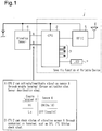
Fig. 1 is a block diagram showing one embodiment of a portable device according to the present invention. - One embodiment of a
portable device 1 will now be described. - As shown in
Fig. 1 , theportable device 1 is a component of SMART KEY SYSTEM (registered trademark). Theportable device 1 may be powered by a battery as shown inFig. 1 . Theportable device 1 is configured to perform bidirectional communication with a vehicle, which is not shown in the drawing. Additionally, theportable device 1 is configured to function as a communication initiation device of one-way communication. The vehicle is one example of a communication peer device of theportable device 1. Theportable device 1 may be a portable electronic key device or key fob. - In SMART KEY SYSTEM, bidirectional communication may be also referred to as smart communication. When the
portable device 1 is validated by key verification performed through the smart communication, theportable device 1 or the user carrying theportable device 1 is allowed to control the vehicle. Additionally, when a remote keyless entry button (not shown) arranged on theportable device 1 is pressed, theportable device 1 starts to perform one-way communication with the vehicle. When theportable device 1 is validated by key verification performed through the one-way communication, the vehicle executes control (e.g., locking and unlocking of door, engine start) corresponding to the operation performed on the remote keyless entry button of theportable device 1. - The
portable device 1 includes aCPU 2, a coil antenna set 3, and anRFIC 5. TheCPU 2 functions as a portable device controller. Thecoil antenna set 3 is configured to receive LF signals (e.g., radio wave signals in LF band) from the vehicle, which is the communication peer. TheRFIC 5 is configured to transmit RF signals (e.g., radio wave signals in UHF) through anantenna 4. The coil antenna set 3 may include an X-axis antenna, a Y-axis antenna, and a Z-axis antenna. - The
portable device 1 includes avibration sensor 6, which is configured to detect vibration of theportable device 1. - The
CPU 2 is connected to thevibration sensor 6 so that synchronous serial communication of a SPI specification or I2C specification is performed between theCPU 2 and thevibration sensor 6. TheCPU 2 periodically checks the status of thevibration sensor 6 in compliance with the synchronous serial communication protocol. When the status of thevibration sensor 6 is normal, theCPU 2 determines that thevibration sensor 6 is not defective. TheCPU 2 switches an enable terminal A of thevibration sensor 6 to a Hi level thereby validating an interruption signal, which may be a vibration detection signal provided from a synchronous serial communication terminal B of thevibration sensor 6. For example, when thevibration sensor 6 detects vibration of theportable device 1, thevibration sensor 6 provides the interruption signal to theCPU 2. At this time, if theCPU 2 determines that thevibration sensor 6 is not defective, the interruption signal to theCPU 2 is validated. TheCPU 2 executes an interruption process to activate a communication standby function (i.e., bidirectional communication initiation signal waiting function) and has the coil antenna set 3 wait to receive the LF signal. When theCPU 2 receives the LF signal, theCPU 2 transmits the RF signal to the vehicle through theRFIC 5 and theantenna 4 in response. This establishes the smart communication between the vehicle and theportable device 1. - When the status of the
vibration sensor 6 is abnormal, theCPU 2 determines that thevibration sensor 6 is defective. TheCPU 2 switches the enable terminal A to a Lo level thereby invalidating inputs from thevibration sensor 6. For example, the interruption signal transmitted from thevibration sensor 6 to theCPU 2 is invalidated. As described above, when thevibration sensor 6 is defective, theCPU 2 disconnects thevibration sensor 6 from theCPU 2 to prevent behaviors (e.g., erroneous vibration detection, incapability of outputting interruption signal) of thevibration sensor 6 from affecting theCPU 2. TheCPU 2 disconnects thevibration sensor 6, for example, in terms of electric signals. In this case, theCPU 2 activates the communication standby function (bidirectional communication initiation signal waiting function) to have the coil antenna set 3 wait to receive the LF signal whether or not the interruption signal is provided from thevibration sensor 6. When theCPU 2 receives the LF signal, theCPU 2 transmits the RF signal to the vehicle through theRFIC 5 and theantenna 4 in response. This allows for establishment of the smart communication between theportable device 1 and the vehicle even when thevibration sensor 6 is defective. Thus, the failsafe capability of theportable device 1 is increased. - The LF signal transmitted from the vehicle is one example of a wireless signal that initiates the smart communication. The function that has the coil antenna set 3 wait to receive the LF signal is included in a smart communication function, which is one example of a specific function of the
portable device 1. TheCPU 2 is one example of a controller. The coil antenna set 3 is one example of a wireless signal receiver or reception antenna. - The
portable device 1 may include anLED 7, which is controlled by theCPU 2 to perform a notification operation. When the remote keyless entry button is pressed, theCPU 2, for example, temporarily illuminates theLED 7 in red to issue a visual notification indicating that theportable device 1 is performing one-way communication. When theCPU 2 determines that thevibration sensor 6 is defective, theCPU 2, for example, intermittently illuminates theLED 7 in red to visually notify the user of theportable device 1 that theportable device 1 is abnormal. TheLED 7 corresponds to a notifying means. - As described above, the embodiment has the operation and advantages described below.
- (1) When the
vibration sensor 6 is defective, theCPU 2 disconnects thevibration sensor 6 so that behaviors of thedefective vibration sensor 6 do not affect theCPU 2. In the normal state, in which thevibration sensor 6 is not defective, the specific function of the portable device is executed by the interruption of thevibration sensor 6. In the embodiment, the specific function of the portable device is executed even when thevibration sensor 6 is defective. Thus, the failsafe capability of theportable device 1 is increased. This prevents or minimizes decreases in the usability of theportable device 1 that would be caused by thedefective vibration sensor 6. - (2) As compared to asynchronous serial communication (e.g., RS-232C serial communication), the communication speed is increased. Thus, whether or not the
vibration sensor 6 is defective is quickly determined. - (3) After the defection of the
vibration sensor 6 is determined, inputs from thevibration sensor 6 are disregarded. This allows for operation that disconnects thedefective vibration sensor 6. - (4) The
portable device 1 is capable of performing the smart communication function even when thevibration sensor 6 is defective. This prevents or minimizes decreases in the usability of theportable device 1 that would be caused by thedefective vibration sensor 6. - (5) The notification operation of the
LED 7 may prompt the user of theportable device 1 to replace or repair theportable device 1. - (6) In the normal state, in which the
vibration sensor 6 is not defective, when thevibration sensor 6 detects vibration of theportable device 1, thevibration sensor 6 provides an interruption signal to theCPU 2. When theCPU 2 receives the interruption signal, theCPU 2 activates the communication standby function, which has the coil antenna set 3 wait to receive the LF signal. For example, when theportable device 1 is stored in a stationary state that receives no external vibration, the communication standby function, which is one of multiple functions of theCPU 2, is deactivated. This decreases the standby current by an amount corresponding to the deactivation of the communication standby function. This state may be referred to as a communication suspension state in which bidirectional communication between the portable electronic key device and the communication peer device is disabled and the communication suspension state consumes less power than the communication ready state. Thus, the battery life of theportable device 1 is prolonged. Additionally, the smart communication is limited by a means that differs from the intention of the user. Thus, the security of SMART KEY SYSTEM is improved. - It should be apparent to those skilled in the art that the present invention may be embodied in many other specific forms without departing from the scope of the invention. Particularly, it should be understood that the present invention may be embodied in the following forms.
- The status of the
vibration sensor 6 may be checked by theCPU 2 through communication performable over a longer transmission distance than the synchronous serial communication of a SPI specification or I2C specification. - The
CPU 2 or thevibration sensor 6 may have a threshold value that detects vibration of theportable device 1. The threshold value may be compared with the level of an output signal from the vibration sensor to detect the vibration. - For example, an acceleration sensor may be used as the
vibration sensor 6. - The LF signal, which is a low frequency wave, is not limited to a radio wave in the LF band.
- The RF signal, which is a high frequency wave, is not limited to a radio wave in the UHF band.
- The
portable device 1 may issue an audial notification such as a buzzing sound or a tactile notification such as vibration instead of or in addition to the visual notification. - The communication peer device of the
portable device 1 is not limited to a vehicle and may be a non-vehicular device such as a building. For example, when an electronic key system includes theportable device 1 and the communication peer device, which may be a building, bidirectional communication is initiated between theportable device 1 and the communication peer device by an LF signal transmitted from the communication peer device. When theportable device 1 is validated by key verification performed through the bidirectional communication, theportable device 1 or the user carrying theportable device 1 is allowed to control the building (or door, illumination device, electric appliance) as the communication peer device. - The present disclosure encompasses the following implementations.
- [Implementation 1] A portable electronic key device used with a communication peer device and capable of performing bidirectional communication with the communication peer device, wherein the bidirectional communication is initiated by a bidirectional communication initiation signal transmitted from the communication peer device, the portable electronic key device being characterized by: a vibration sensor that detects vibration of the portable electronic key device; a reception antenna configured to receive the bidirectional communication initiation signal; a transmission antenna that transmits a response signal to the communication peer device in response to the bidirectional communication initiation signal; and
a controller connected to the vibration sensor, wherein the controller is configured to: determine whether or not the vibration sensor is defective; activate a bidirectional communication initiation signal waiting function when the vibration sensor is functioning normally and the controller receives a vibration detection signal from the vibration sensor; deactivate the bidirectional communication initiation signal waiting function when the vibration sensor is functioning normally and the controller does not receive the vibration detection signal from the vibration sensor; and activate the bidirectional communication initiation signal waiting function when the vibration sensor is defective regardless of whether or not the vibration detection signal is received from the vibration sensor. - [Implementation 2] A portable electronic key device used with a communication peer device and capable of performing bidirectional communication with the communication peer device, wherein the bidirectional communication is initiated by a bidirectional communication initiation signal transmitted from the communication peer device, the portable electronic key device being characterized by: a vibration sensor that detects vibration of the portable electronic key device; a reception antenna configured to receive the bidirectional communication initiation signal; a transmission antenna that transmits a response signal to the communication peer device in response to the bidirectional communication initiation signal; and a controller connected to the vibration sensor, wherein the controller is configured to: determine whether or not the vibration sensor is defective; shift the portable electronic key device to a communication ready state when the vibration sensor is functioning normally and the controller receives a vibration detection signal from the vibration sensor, wherein the communication ready state allows for bidirectional communication between the portable electronic key device and the communication peer device; shift the portable electronic key device to a communication suspension state when the vibration sensor is functioning normally and the controller does not receives the vibration detection signal from the vibration sensor, wherein the communication suspension state disables bidirectional communication between the portable electronic key device and the communication peer device, and the communication suspension state consumes less power than the communication ready state; and shift the portable electronic key device to the communication ready state when the vibration sensor is defective regardless of whether or not the vibration detection signal is received from the vibration sensor.
- [Implementation 3] A method of operating a portable electronic key device used with a communication peer device and capable of performing bidirectional communication with the communication peer device, wherein the bidirectional communication is initiated by a bidirectional communication initiation signal transmitted from the communication peer device, the portable electronic key device including: a vibration sensor that detects vibration of the portable electronic key device, a reception antenna configured to receive the bidirectional communication initiation signal, a transmission antenna that transmits a response signal to the communication peer device in response to the bidirectional communication initiation signal, and a controller connected to the vibration sensor, the method comprising: determining, by the the controller, whether or not the vibration sensor is defective; activating, by the the controller, a bidirectional communication initiation signal waiting function when the vibration sensor is functioning normally and the controller receives a vibration detection signal from the vibration sensor; deactivating, by the the controller, the bidirectional communication initiation signal waiting function when the vibration sensor is functioning normally and the controller does not receive the vibration detection signal from the vibration sensor; and activating, by the the controller, the bidirectional communication initiation signal waiting function when the vibration sensor is defective regardless of whether or not the vibration detection signal is received from the vibration sensor.
- [Implementation 4] A method of operating a portable electronic key device used with a communication peer device and capable of performing bidirectional communication with the communication peer device, wherein the bidirectional communication is initiated by a bidirectional communication initiation signal transmitted from the communication peer device, the portable electronic key device including: a vibration sensor that detects vibration of the portable electronic key device, a reception antenna configured to receive the bidirectional communication initiation signal, a transmission antenna that transmits a response signal to the communication peer device in response to the bidirectional communication initiation signal, and a controller connected to the vibration sensor, the method comprising: determining, by the controller, whether or not the vibration sensor is defective; shifting, by the controller, the portable electronic key device to a communication ready state when the vibration sensor is functioning normally and the controller receives a vibration detection signal from the vibration sensor, wherein the communication ready state allows for bidirectional communication between the portable electronic key device and the communication peer device; shifting, by the controller, the portable electronic key device to a communication suspension state when the vibration sensor is functioning normally and the controller does not receives the vibration detection signal from the vibration sensor, wherein the communication suspension state disables bidirectional communication between the portable electronic key device and the communication peer device, and the communication suspension state consumes less power than the communication ready state; and shifting, by the controller, the portable electronic key device to the communication ready state when the vibration sensor is defective regardless of whether or not the vibration detection signal is received from the vibration sensor.
- The present examples and embodiments are to be considered as illustrative and not restrictive, and the invention is not to be limited to the details given herein, but may be modified within the scope and equivalence of the appended claims. For example, one or more of the components may be omitted from the components described in the embodiments (or one or more aspects thereof). Components in different embodiments may be appropriately combined.
- A portable device (1) includes a vibration sensor (6) and a controller (2). The controller (2) checks a status of the vibration sensor (6). When the check result indicates that the vibration sensor (6) is defective, the controller (2) disconnects the vibration sensor (6) and operates the portable device (1).
Claims (5)
- A portable device (1) that includes a vibration sensor (6), the portable device (1) being characterized by a controller (2) that checks a status of the vibration sensor (6), wherein when the controller (2) determines that the vibration sensor (6) is defective, the controller (2) disconnects the vibration sensor (6) and operates the portable device (1).
- The portable device (1) according to claim 1, characterized in that the controller (2) is configured to periodically check the status of the vibration sensor (6) in compliance with a synchronous serial communication protocol of a SPI specification or I2C specification.
- The portable device (1) according to claim 1 or 2, characterized in that the controller (2) is configured to invalidate an input from the vibration sensor (6) when the controller (2) determines that the vibration sensor (6) is defective.
- The portable device (1) according to any one of claims 1 to 3, characterized by a wireless signal receiver (3) configured to receive a wireless signal from a communication peer device, wherein
the vibration sensor (6) is configured to provide an interruption signal to the controller (2) when the vibration sensor (6) detects vibration of the portable device (1),
the controller (2) is configured to execute a specific function of the portable device (1) when provided with the interruption signal from the vibration sensor (6),
the specific function of the portable device (1) includes a communication standby function that has the wireless signal receiver (3) wait to receive the wireless signal, and
the controller (2) is configured to activate the specific function of the portable device (1) when the controller (2) detects that the vibration sensor (6) is defective regardless of whether or not the interruption signal is provided from the vibration sensor (6). - The portable device (1) according to claim 1 to 4, characterized by a notifying means (7) that is actuated to issue a notification indicating an abnormality of the portable device (1) when the controller (2) determines that the vibration sensor (6) is defective.
Applications Claiming Priority (1)
| Application Number | Priority Date | Filing Date | Title |
|---|---|---|---|
| JP2016135247A JP6453817B2 (en) | 2016-07-07 | 2016-07-07 | Portable machine |
Publications (2)
| Publication Number | Publication Date |
|---|---|
| EP3267317A1 true EP3267317A1 (en) | 2018-01-10 |
| EP3267317B1 EP3267317B1 (en) | 2020-07-29 |
Family
ID=59381044
Family Applications (1)
| Application Number | Title | Priority Date | Filing Date |
|---|---|---|---|
| EP17178954.8A Active EP3267317B1 (en) | 2016-07-07 | 2017-06-30 | Portable device with vibration sensor |
Country Status (3)
| Country | Link |
|---|---|
| EP (1) | EP3267317B1 (en) |
| JP (1) | JP6453817B2 (en) |
| KR (1) | KR102005622B1 (en) |
Cited By (1)
| Publication number | Priority date | Publication date | Assignee | Title |
|---|---|---|---|---|
| CN110239482A (en) * | 2018-03-09 | 2019-09-17 | 丰田自动车株式会社 | Mobile device and vehicle |
Citations (2)
| Publication number | Priority date | Publication date | Assignee | Title |
|---|---|---|---|---|
| US20060043181A1 (en) * | 2004-08-27 | 2006-03-02 | Denso Corporation | Portable device for electronic key system and system for reminding user to carry portable device |
| JP2013037632A (en) | 2011-08-10 | 2013-02-21 | Tokai Rika Co Ltd | Power supply circuit for electronic equipment |
Family Cites Families (8)
| Publication number | Priority date | Publication date | Assignee | Title |
|---|---|---|---|---|
| JP3556418B2 (en) * | 1996-12-04 | 2004-08-18 | 株式会社東芝 | Method and apparatus for removing vibration sensor in furnace |
| JP2000295677A (en) * | 1999-04-02 | 2000-10-20 | Omron Corp | Sensor system and sensor |
| JP4342632B2 (en) * | 1999-04-06 | 2009-10-14 | ブリヂストンサイクル株式会社 | Bicycle lock device |
| KR100854297B1 (en) * | 2007-01-22 | 2008-08-26 | (주)대양디앤티 | Door lock equipped with a vibration sensor and a method of generating an alarm in the door lock |
| JP5232762B2 (en) * | 2009-12-07 | 2013-07-10 | 株式会社日立製作所 | RADIO COMMUNICATION DEVICE, RADIO COMMUNICATION DEVICE CONTROL METHOD, AND SENSOR NET SYSTEM USING RADIO COMMUNICATION DEVICE |
| CN103069837B (en) * | 2010-08-18 | 2016-05-04 | 三菱电机株式会社 | Electric device and control method |
| JP2012235200A (en) * | 2011-04-28 | 2012-11-29 | Hitachi-Ge Nuclear Energy Ltd | Emergency stop system of working device, emergency stop device and working device |
| WO2015125617A1 (en) * | 2014-02-24 | 2015-08-27 | 日立オートモティブシステムズステアリング株式会社 | In-vehicle device controller and power steering device |
-
2016
- 2016-07-07 JP JP2016135247A patent/JP6453817B2/en active Active
-
2017
- 2017-06-22 KR KR1020170079232A patent/KR102005622B1/en not_active Expired - Fee Related
- 2017-06-30 EP EP17178954.8A patent/EP3267317B1/en active Active
Patent Citations (2)
| Publication number | Priority date | Publication date | Assignee | Title |
|---|---|---|---|---|
| US20060043181A1 (en) * | 2004-08-27 | 2006-03-02 | Denso Corporation | Portable device for electronic key system and system for reminding user to carry portable device |
| JP2013037632A (en) | 2011-08-10 | 2013-02-21 | Tokai Rika Co Ltd | Power supply circuit for electronic equipment |
Cited By (4)
| Publication number | Priority date | Publication date | Assignee | Title |
|---|---|---|---|---|
| CN110239482A (en) * | 2018-03-09 | 2019-09-17 | 丰田自动车株式会社 | Mobile device and vehicle |
| CN114475519A (en) * | 2018-03-09 | 2022-05-13 | 丰田自动车株式会社 | Mobile device and vehicle |
| CN114475519B (en) * | 2018-03-09 | 2024-05-28 | 丰田自动车株式会社 | Mobile equipment and vehicles |
| DE102019104584B4 (en) * | 2018-03-09 | 2025-07-31 | Toyota Jidosha Kabushiki Kaisha | Portable device and vehicle |
Also Published As
| Publication number | Publication date |
|---|---|
| KR102005622B1 (en) | 2019-07-30 |
| JP6453817B2 (en) | 2019-01-16 |
| KR20180006293A (en) | 2018-01-17 |
| JP2018007177A (en) | 2018-01-11 |
| EP3267317B1 (en) | 2020-07-29 |
Similar Documents
| Publication | Publication Date | Title |
|---|---|---|
| US10547989B2 (en) | Terminal, vehicle control system, and vehicle control method | |
| EP3434535B1 (en) | Vehicular electronic key system and method of controlling electronic key | |
| JP5980175B2 (en) | Report system, report control method, and portable terminal | |
| US9738254B2 (en) | Tire theft alarm system | |
| US9401081B2 (en) | Vehicle communication device | |
| EP3192949B1 (en) | Portable device | |
| US11298990B2 (en) | Tire pressure monitoring system | |
| EP3462421B1 (en) | Electronic vehicle key with power saving mode | |
| CN108973933B (en) | Control system, vehicle equipment and electronic key | |
| JP2013048517A (en) | In-vehicle portable terminal charging device | |
| US11299912B2 (en) | Vehicle electronic key | |
| JP2015003545A (en) | Portable machine-searching device, portable machine-searching method, and portable machine-searching program | |
| JP6760206B2 (en) | In-vehicle authentication device, portable device authentication method | |
| EP3267317B1 (en) | Portable device with vibration sensor | |
| US9474024B2 (en) | Mobile communication apparatus switching on and off state with distance from communicating external apparatus | |
| EP3280152A1 (en) | Transmission device, receiving device, and communication system and remote operation device provided with same | |
| JP2013227828A (en) | Wireless communication system | |
| JP4800297B2 (en) | How to automatically block the opening of a car | |
| WO2021039910A1 (en) | Abnormality detection device and electronic key | |
| JP2012188800A (en) | Electronic key system | |
| KR102519398B1 (en) | Electronic device for controlling vehicle and operation mehtod thereof | |
| JP2019043160A (en) | Vehicle control system | |
| JP2019066301A (en) | Communication terminal | |
| JP5529787B2 (en) | Electronic key and electronic key system | |
| KR20140017830A (en) | Emergency starting apparatus and method in smartkey system |
Legal Events
| Date | Code | Title | Description |
|---|---|---|---|
| PUAI | Public reference made under article 153(3) epc to a published international application that has entered the european phase |
Free format text: ORIGINAL CODE: 0009012 |
|
| STAA | Information on the status of an ep patent application or granted ep patent |
Free format text: STATUS: THE APPLICATION HAS BEEN PUBLISHED |
|
| AK | Designated contracting states |
Kind code of ref document: A1 Designated state(s): AL AT BE BG CH CY CZ DE DK EE ES FI FR GB GR HR HU IE IS IT LI LT LU LV MC MK MT NL NO PL PT RO RS SE SI SK SM TR |
|
| AX | Request for extension of the european patent |
Extension state: BA ME |
|
| STAA | Information on the status of an ep patent application or granted ep patent |
Free format text: STATUS: REQUEST FOR EXAMINATION WAS MADE |
|
| 17P | Request for examination filed |
Effective date: 20180627 |
|
| RBV | Designated contracting states (corrected) |
Designated state(s): AL AT BE BG CH CY CZ DE DK EE ES FI FR GB GR HR HU IE IS IT LI LT LU LV MC MK MT NL NO PL PT RO RS SE SI SK SM TR |
|
| GRAP | Despatch of communication of intention to grant a patent |
Free format text: ORIGINAL CODE: EPIDOSNIGR1 |
|
| STAA | Information on the status of an ep patent application or granted ep patent |
Free format text: STATUS: GRANT OF PATENT IS INTENDED |
|
| INTG | Intention to grant announced |
Effective date: 20200226 |
|
| GRAS | Grant fee paid |
Free format text: ORIGINAL CODE: EPIDOSNIGR3 |
|
| GRAA | (expected) grant |
Free format text: ORIGINAL CODE: 0009210 |
|
| STAA | Information on the status of an ep patent application or granted ep patent |
Free format text: STATUS: THE PATENT HAS BEEN GRANTED |
|
| AK | Designated contracting states |
Kind code of ref document: B1 Designated state(s): AL AT BE BG CH CY CZ DE DK EE ES FI FR GB GR HR HU IE IS IT LI LT LU LV MC MK MT NL NO PL PT RO RS SE SI SK SM TR |
|
| REG | Reference to a national code |
Ref country code: CH Ref legal event code: EP |
|
| REG | Reference to a national code |
Ref country code: AT Ref legal event code: REF Ref document number: 1296590 Country of ref document: AT Kind code of ref document: T Effective date: 20200815 |
|
| REG | Reference to a national code |
Ref country code: IE Ref legal event code: FG4D |
|
| REG | Reference to a national code |
Ref country code: DE Ref legal event code: R096 Ref document number: 602017020439 Country of ref document: DE |
|
| REG | Reference to a national code |
Ref country code: LT Ref legal event code: MG4D |
|
| REG | Reference to a national code |
Ref country code: NL Ref legal event code: MP Effective date: 20200729 |
|
| REG | Reference to a national code |
Ref country code: AT Ref legal event code: MK05 Ref document number: 1296590 Country of ref document: AT Kind code of ref document: T Effective date: 20200729 |
|
| PG25 | Lapsed in a contracting state [announced via postgrant information from national office to epo] |
Ref country code: LT Free format text: LAPSE BECAUSE OF FAILURE TO SUBMIT A TRANSLATION OF THE DESCRIPTION OR TO PAY THE FEE WITHIN THE PRESCRIBED TIME-LIMIT Effective date: 20200729 Ref country code: HR Free format text: LAPSE BECAUSE OF FAILURE TO SUBMIT A TRANSLATION OF THE DESCRIPTION OR TO PAY THE FEE WITHIN THE PRESCRIBED TIME-LIMIT Effective date: 20200729 Ref country code: BG Free format text: LAPSE BECAUSE OF FAILURE TO SUBMIT A TRANSLATION OF THE DESCRIPTION OR TO PAY THE FEE WITHIN THE PRESCRIBED TIME-LIMIT Effective date: 20201029 Ref country code: SE Free format text: LAPSE BECAUSE OF FAILURE TO SUBMIT A TRANSLATION OF THE DESCRIPTION OR TO PAY THE FEE WITHIN THE PRESCRIBED TIME-LIMIT Effective date: 20200729 Ref country code: ES Free format text: LAPSE BECAUSE OF FAILURE TO SUBMIT A TRANSLATION OF THE DESCRIPTION OR TO PAY THE FEE WITHIN THE PRESCRIBED TIME-LIMIT Effective date: 20200729 Ref country code: GR Free format text: LAPSE BECAUSE OF FAILURE TO SUBMIT A TRANSLATION OF THE DESCRIPTION OR TO PAY THE FEE WITHIN THE PRESCRIBED TIME-LIMIT Effective date: 20201030 Ref country code: PT Free format text: LAPSE BECAUSE OF FAILURE TO SUBMIT A TRANSLATION OF THE DESCRIPTION OR TO PAY THE FEE WITHIN THE PRESCRIBED TIME-LIMIT Effective date: 20201130 Ref country code: NO Free format text: LAPSE BECAUSE OF FAILURE TO SUBMIT A TRANSLATION OF THE DESCRIPTION OR TO PAY THE FEE WITHIN THE PRESCRIBED TIME-LIMIT Effective date: 20201029 Ref country code: FI Free format text: LAPSE BECAUSE OF FAILURE TO SUBMIT A TRANSLATION OF THE DESCRIPTION OR TO PAY THE FEE WITHIN THE PRESCRIBED TIME-LIMIT Effective date: 20200729 Ref country code: AT Free format text: LAPSE BECAUSE OF FAILURE TO SUBMIT A TRANSLATION OF THE DESCRIPTION OR TO PAY THE FEE WITHIN THE PRESCRIBED TIME-LIMIT Effective date: 20200729 |
|
| PG25 | Lapsed in a contracting state [announced via postgrant information from national office to epo] |
Ref country code: RS Free format text: LAPSE BECAUSE OF FAILURE TO SUBMIT A TRANSLATION OF THE DESCRIPTION OR TO PAY THE FEE WITHIN THE PRESCRIBED TIME-LIMIT Effective date: 20200729 Ref country code: LV Free format text: LAPSE BECAUSE OF FAILURE TO SUBMIT A TRANSLATION OF THE DESCRIPTION OR TO PAY THE FEE WITHIN THE PRESCRIBED TIME-LIMIT Effective date: 20200729 Ref country code: PL Free format text: LAPSE BECAUSE OF FAILURE TO SUBMIT A TRANSLATION OF THE DESCRIPTION OR TO PAY THE FEE WITHIN THE PRESCRIBED TIME-LIMIT Effective date: 20200729 Ref country code: IS Free format text: LAPSE BECAUSE OF FAILURE TO SUBMIT A TRANSLATION OF THE DESCRIPTION OR TO PAY THE FEE WITHIN THE PRESCRIBED TIME-LIMIT Effective date: 20201129 |
|
| PG25 | Lapsed in a contracting state [announced via postgrant information from national office to epo] |
Ref country code: NL Free format text: LAPSE BECAUSE OF FAILURE TO SUBMIT A TRANSLATION OF THE DESCRIPTION OR TO PAY THE FEE WITHIN THE PRESCRIBED TIME-LIMIT Effective date: 20200729 |
|
| PG25 | Lapsed in a contracting state [announced via postgrant information from national office to epo] |
Ref country code: CZ Free format text: LAPSE BECAUSE OF FAILURE TO SUBMIT A TRANSLATION OF THE DESCRIPTION OR TO PAY THE FEE WITHIN THE PRESCRIBED TIME-LIMIT Effective date: 20200729 Ref country code: DK Free format text: LAPSE BECAUSE OF FAILURE TO SUBMIT A TRANSLATION OF THE DESCRIPTION OR TO PAY THE FEE WITHIN THE PRESCRIBED TIME-LIMIT Effective date: 20200729 Ref country code: RO Free format text: LAPSE BECAUSE OF FAILURE TO SUBMIT A TRANSLATION OF THE DESCRIPTION OR TO PAY THE FEE WITHIN THE PRESCRIBED TIME-LIMIT Effective date: 20200729 Ref country code: IT Free format text: LAPSE BECAUSE OF FAILURE TO SUBMIT A TRANSLATION OF THE DESCRIPTION OR TO PAY THE FEE WITHIN THE PRESCRIBED TIME-LIMIT Effective date: 20200729 Ref country code: EE Free format text: LAPSE BECAUSE OF FAILURE TO SUBMIT A TRANSLATION OF THE DESCRIPTION OR TO PAY THE FEE WITHIN THE PRESCRIBED TIME-LIMIT Effective date: 20200729 Ref country code: SM Free format text: LAPSE BECAUSE OF FAILURE TO SUBMIT A TRANSLATION OF THE DESCRIPTION OR TO PAY THE FEE WITHIN THE PRESCRIBED TIME-LIMIT Effective date: 20200729 |
|
| REG | Reference to a national code |
Ref country code: DE Ref legal event code: R097 Ref document number: 602017020439 Country of ref document: DE |
|
| PG25 | Lapsed in a contracting state [announced via postgrant information from national office to epo] |
Ref country code: AL Free format text: LAPSE BECAUSE OF FAILURE TO SUBMIT A TRANSLATION OF THE DESCRIPTION OR TO PAY THE FEE WITHIN THE PRESCRIBED TIME-LIMIT Effective date: 20200729 |
|
| PLBE | No opposition filed within time limit |
Free format text: ORIGINAL CODE: 0009261 |
|
| STAA | Information on the status of an ep patent application or granted ep patent |
Free format text: STATUS: NO OPPOSITION FILED WITHIN TIME LIMIT |
|
| PG25 | Lapsed in a contracting state [announced via postgrant information from national office to epo] |
Ref country code: SK Free format text: LAPSE BECAUSE OF FAILURE TO SUBMIT A TRANSLATION OF THE DESCRIPTION OR TO PAY THE FEE WITHIN THE PRESCRIBED TIME-LIMIT Effective date: 20200729 |
|
| 26N | No opposition filed |
Effective date: 20210430 |
|
| PG25 | Lapsed in a contracting state [announced via postgrant information from national office to epo] |
Ref country code: SI Free format text: LAPSE BECAUSE OF FAILURE TO SUBMIT A TRANSLATION OF THE DESCRIPTION OR TO PAY THE FEE WITHIN THE PRESCRIBED TIME-LIMIT Effective date: 20200729 |
|
| PG25 | Lapsed in a contracting state [announced via postgrant information from national office to epo] |
Ref country code: MC Free format text: LAPSE BECAUSE OF FAILURE TO SUBMIT A TRANSLATION OF THE DESCRIPTION OR TO PAY THE FEE WITHIN THE PRESCRIBED TIME-LIMIT Effective date: 20200729 |
|
| REG | Reference to a national code |
Ref country code: CH Ref legal event code: PL |
|
| REG | Reference to a national code |
Ref country code: BE Ref legal event code: MM Effective date: 20210630 |
|
| PG25 | Lapsed in a contracting state [announced via postgrant information from national office to epo] |
Ref country code: LU Free format text: LAPSE BECAUSE OF NON-PAYMENT OF DUE FEES Effective date: 20210630 |
|
| PG25 | Lapsed in a contracting state [announced via postgrant information from national office to epo] |
Ref country code: LI Free format text: LAPSE BECAUSE OF NON-PAYMENT OF DUE FEES Effective date: 20210630 Ref country code: IE Free format text: LAPSE BECAUSE OF NON-PAYMENT OF DUE FEES Effective date: 20210630 Ref country code: CH Free format text: LAPSE BECAUSE OF NON-PAYMENT OF DUE FEES Effective date: 20210630 |
|
| PG25 | Lapsed in a contracting state [announced via postgrant information from national office to epo] |
Ref country code: FR Free format text: LAPSE BECAUSE OF NON-PAYMENT OF DUE FEES Effective date: 20210630 |
|
| PG25 | Lapsed in a contracting state [announced via postgrant information from national office to epo] |
Ref country code: BE Free format text: LAPSE BECAUSE OF NON-PAYMENT OF DUE FEES Effective date: 20210630 |
|
| PG25 | Lapsed in a contracting state [announced via postgrant information from national office to epo] |
Ref country code: HU Free format text: LAPSE BECAUSE OF FAILURE TO SUBMIT A TRANSLATION OF THE DESCRIPTION OR TO PAY THE FEE WITHIN THE PRESCRIBED TIME-LIMIT; INVALID AB INITIO Effective date: 20170630 |
|
| PG25 | Lapsed in a contracting state [announced via postgrant information from national office to epo] |
Ref country code: CY Free format text: LAPSE BECAUSE OF FAILURE TO SUBMIT A TRANSLATION OF THE DESCRIPTION OR TO PAY THE FEE WITHIN THE PRESCRIBED TIME-LIMIT Effective date: 20200729 |
|
| PG25 | Lapsed in a contracting state [announced via postgrant information from national office to epo] |
Ref country code: MK Free format text: LAPSE BECAUSE OF FAILURE TO SUBMIT A TRANSLATION OF THE DESCRIPTION OR TO PAY THE FEE WITHIN THE PRESCRIBED TIME-LIMIT Effective date: 20200729 |
|
| PG25 | Lapsed in a contracting state [announced via postgrant information from national office to epo] |
Ref country code: TR Free format text: LAPSE BECAUSE OF FAILURE TO SUBMIT A TRANSLATION OF THE DESCRIPTION OR TO PAY THE FEE WITHIN THE PRESCRIBED TIME-LIMIT Effective date: 20200729 |
|
| PG25 | Lapsed in a contracting state [announced via postgrant information from national office to epo] |
Ref country code: MT Free format text: LAPSE BECAUSE OF FAILURE TO SUBMIT A TRANSLATION OF THE DESCRIPTION OR TO PAY THE FEE WITHIN THE PRESCRIBED TIME-LIMIT Effective date: 20200729 |
|
| PGFP | Annual fee paid to national office [announced via postgrant information from national office to epo] |
Ref country code: DE Payment date: 20250507 Year of fee payment: 9 |
|
| PGFP | Annual fee paid to national office [announced via postgrant information from national office to epo] |
Ref country code: GB Payment date: 20250508 Year of fee payment: 9 |