EP3267209A1 - Apparatus for measuring electrical currents in electrical conductors - Google Patents
Apparatus for measuring electrical currents in electrical conductors Download PDFInfo
- Publication number
- EP3267209A1 EP3267209A1 EP17180179.8A EP17180179A EP3267209A1 EP 3267209 A1 EP3267209 A1 EP 3267209A1 EP 17180179 A EP17180179 A EP 17180179A EP 3267209 A1 EP3267209 A1 EP 3267209A1
- Authority
- EP
- European Patent Office
- Prior art keywords
- electrical
- coils
- measuring apparatus
- armatures
- current
- Prior art date
- Legal status (The legal status is an assumption and is not a legal conclusion. Google has not performed a legal analysis and makes no representation as to the accuracy of the status listed.)
- Granted
Links
- 239000004020 conductor Substances 0.000 title claims abstract description 76
- 230000005294 ferromagnetic effect Effects 0.000 claims abstract description 33
- 238000004804 winding Methods 0.000 claims description 14
- XEEYBQQBJWHFJM-UHFFFAOYSA-N Iron Chemical compound [Fe] XEEYBQQBJWHFJM-UHFFFAOYSA-N 0.000 claims description 6
- 229910000640 Fe alloy Inorganic materials 0.000 claims description 3
- 229910005347 FeSi Inorganic materials 0.000 claims description 3
- 229910001030 Iron–nickel alloy Inorganic materials 0.000 claims description 3
- 229910052742 iron Inorganic materials 0.000 claims description 3
- 230000002787 reinforcement Effects 0.000 claims 1
- 238000000429 assembly Methods 0.000 description 17
- 230000000712 assembly Effects 0.000 description 17
- 238000005259 measurement Methods 0.000 description 12
- 239000003990 capacitor Substances 0.000 description 8
- 238000010616 electrical installation Methods 0.000 description 6
- 238000004519 manufacturing process Methods 0.000 description 4
- 230000000295 complement effect Effects 0.000 description 3
- 230000007547 defect Effects 0.000 description 3
- 230000004907 flux Effects 0.000 description 3
- 238000009434 installation Methods 0.000 description 3
- 230000005291 magnetic effect Effects 0.000 description 3
- 230000004044 response Effects 0.000 description 3
- RYGMFSIKBFXOCR-UHFFFAOYSA-N Copper Chemical compound [Cu] RYGMFSIKBFXOCR-UHFFFAOYSA-N 0.000 description 2
- 239000004952 Polyamide Substances 0.000 description 2
- 230000008859 change Effects 0.000 description 2
- 229910052802 copper Inorganic materials 0.000 description 2
- 239000010949 copper Substances 0.000 description 2
- 238000000151 deposition Methods 0.000 description 2
- 238000001514 detection method Methods 0.000 description 2
- 230000005684 electric field Effects 0.000 description 2
- 238000010292 electrical insulation Methods 0.000 description 2
- 238000002955 isolation Methods 0.000 description 2
- 239000002184 metal Substances 0.000 description 2
- 229910052751 metal Inorganic materials 0.000 description 2
- 230000005405 multipole Effects 0.000 description 2
- 239000004033 plastic Substances 0.000 description 2
- 229920002647 polyamide Polymers 0.000 description 2
- 230000002159 abnormal effect Effects 0.000 description 1
- 229910045601 alloy Inorganic materials 0.000 description 1
- 239000000956 alloy Substances 0.000 description 1
- 230000002457 bidirectional effect Effects 0.000 description 1
- 238000004891 communication Methods 0.000 description 1
- 238000010276 construction Methods 0.000 description 1
- 238000003745 diagnosis Methods 0.000 description 1
- 238000010586 diagram Methods 0.000 description 1
- 239000012777 electrically insulating material Substances 0.000 description 1
- 239000003822 epoxy resin Substances 0.000 description 1
- 238000010438 heat treatment Methods 0.000 description 1
- UGKDIUIOSMUOAW-UHFFFAOYSA-N iron nickel Chemical compound [Fe].[Ni] UGKDIUIOSMUOAW-UHFFFAOYSA-N 0.000 description 1
- 230000007257 malfunction Effects 0.000 description 1
- 239000000463 material Substances 0.000 description 1
- 239000002991 molded plastic Substances 0.000 description 1
- 229920000647 polyepoxide Polymers 0.000 description 1
- 239000007858 starting material Substances 0.000 description 1
- 238000011144 upstream manufacturing Methods 0.000 description 1
- 230000000007 visual effect Effects 0.000 description 1
Images


Classifications
-
- G—PHYSICS
- G01—MEASURING; TESTING
- G01R—MEASURING ELECTRIC VARIABLES; MEASURING MAGNETIC VARIABLES
- G01R15/00—Details of measuring arrangements of the types provided for in groups G01R17/00 - G01R29/00, G01R33/00 - G01R33/26 or G01R35/00
- G01R15/14—Adaptations providing voltage or current isolation, e.g. for high-voltage or high-current networks
- G01R15/18—Adaptations providing voltage or current isolation, e.g. for high-voltage or high-current networks using inductive devices, e.g. transformers
- G01R15/181—Adaptations providing voltage or current isolation, e.g. for high-voltage or high-current networks using inductive devices, e.g. transformers using coils without a magnetic core, e.g. Rogowski coils
-
- G—PHYSICS
- G01—MEASURING; TESTING
- G01R—MEASURING ELECTRIC VARIABLES; MEASURING MAGNETIC VARIABLES
- G01R15/00—Details of measuring arrangements of the types provided for in groups G01R17/00 - G01R29/00, G01R33/00 - G01R33/26 or G01R35/00
- G01R15/14—Adaptations providing voltage or current isolation, e.g. for high-voltage or high-current networks
- G01R15/20—Adaptations providing voltage or current isolation, e.g. for high-voltage or high-current networks using galvano-magnetic devices, e.g. Hall-effect devices, i.e. measuring a magnetic field via the interaction between a current and a magnetic field, e.g. magneto resistive or Hall effect devices
- G01R15/205—Adaptations providing voltage or current isolation, e.g. for high-voltage or high-current networks using galvano-magnetic devices, e.g. Hall-effect devices, i.e. measuring a magnetic field via the interaction between a current and a magnetic field, e.g. magneto resistive or Hall effect devices using magneto-resistance devices, e.g. field plates
-
- G—PHYSICS
- G01—MEASURING; TESTING
- G01R—MEASURING ELECTRIC VARIABLES; MEASURING MAGNETIC VARIABLES
- G01R15/00—Details of measuring arrangements of the types provided for in groups G01R17/00 - G01R29/00, G01R33/00 - G01R33/26 or G01R35/00
- G01R15/14—Adaptations providing voltage or current isolation, e.g. for high-voltage or high-current networks
- G01R15/142—Arrangements for simultaneous measurements of several parameters employing techniques covered by groups G01R15/14 - G01R15/26
-
- G—PHYSICS
- G01—MEASURING; TESTING
- G01R—MEASURING ELECTRIC VARIABLES; MEASURING MAGNETIC VARIABLES
- G01R15/00—Details of measuring arrangements of the types provided for in groups G01R17/00 - G01R29/00, G01R33/00 - G01R33/26 or G01R35/00
- G01R15/14—Adaptations providing voltage or current isolation, e.g. for high-voltage or high-current networks
- G01R15/16—Adaptations providing voltage or current isolation, e.g. for high-voltage or high-current networks using capacitive devices
-
- G—PHYSICS
- G01—MEASURING; TESTING
- G01R—MEASURING ELECTRIC VARIABLES; MEASURING MAGNETIC VARIABLES
- G01R19/00—Arrangements for measuring currents or voltages or for indicating presence or sign thereof
- G01R19/0092—Arrangements for measuring currents or voltages or for indicating presence or sign thereof measuring current only
-
- G—PHYSICS
- G01—MEASURING; TESTING
- G01R—MEASURING ELECTRIC VARIABLES; MEASURING MAGNETIC VARIABLES
- G01R35/00—Testing or calibrating of apparatus covered by the other groups of this subclass
- G01R35/005—Calibrating; Standards or reference devices, e.g. voltage or resistance standards, "golden" references
Definitions
- the present invention relates to an apparatus for measuring electric currents.
- Electrical assemblies are known for controlling the electrical supply of an electric charge and for providing protection for this electric charge.
- motor starting assemblies are known for controlling industrial electric motors, such as asynchronous motors.
- Such an electrical assembly typically comprises, for each electrical load, a circuit breaker and a contactor which control the power supply of this electric charge.
- the circuit breaker located upstream, provides protection of the power supply against anomalies, such as short circuit or overcurrent.
- the downstream contactor selectively interrupts the power supply in response to a control signal.
- the interconnection module electrically connects a power output of the circuit breaker with a power input of the contactor.
- Such an interconnection module is for example described in FR 2806525 A1 .
- the invention intends to remedy more particularly by proposing an apparatus for measuring electric currents which is compact and which has a reduced unit cost and whose industrial manufacture is simplified.
- the invention there is a reliable and compact means for measuring the currents flowing in electrical conductors.
- the modular construction of the meter makes it easier and less expensive to manufacture on an industrial scale.
- the invention relates to a measuring apparatus as described above, characterized in that the ferromagnetic bars are made of an iron alloy, such as soft iron or NiFe or FeSi.
- the invention relates to an assembly comprising an electrical device, electrically powered by electrical conductors and a measuring device, adapted to measure the electric current flowing through each of the electrical conductors.
- the measuring apparatus is as described above, each of the electrical conductors being received within the central receiving area of the corresponding current sensor.
- the figure 1 represents an electrical installation 1 for controlling a set of electrical charges.
- This electrical installation 1 comprises a central control unit 2, also called head of line, and several electrical assemblies 3, each able to control the power supply of an electric charge 4.
- the central unit 2 and the electrical assemblies 3 are fixed along one or more fastening rails 5, for example of the type known as "DIN rail". These electrical assemblies 3 are here identical to each other.
- the electrical charges 4 are industrial electric motors, such as asynchronous motors.
- the assembly 1 may comprise a different number of such electrical assemblies 3. Similarly, only a single motor 4 is illustrated.
- Each of the electrical assemblies 3 is adapted to control the power supply of an electric charge 4. More specifically, each of the electrical assemblies 3 is interposed between a source of electrical energy, not shown, and one of the electrical charges 4. The assemblies 3 are thus adapted to regulate the power supply of this electric charge 4, for example to selectively activate or deactivate the supply of the corresponding electric charge 4.
- the electrical energy source supplies an electric current of supply, here alternating and three-phase.
- each of the electrical assemblies 3 comprises a circuit breaker 10, a contactor 20 and an interconnection module 30 between the circuit breaker 10 and the contactor 20.
- the circuit breaker 10 is adapted to interrupt, in case of anomaly or a security defect, the flow of electric current from the power source.
- This defect is for example an overcurrent or a short circuit.
- the circuit breaker 10 is here a multipole circuit breaker, provided with a plurality of electric poles, each associated with an electrical phase of the electric supply current.
- the circuit breaker 10 comprises, for each pole, an input and a current output connected together by separable electrical contacts internal to the circuit breaker 10. These electrical contacts are switchable between open or closed states, so as, respectively, interrupt or allow the passage of a current between the input and the current output. This switching is performed automatically by a circuit for detecting an electrical fault, in the event of an anomaly such as an overcurrent or a short circuit.
- the current inputs of the circuit breaker 10 are connected to the source of electrical energy.
- the contactor 20 is adapted to interrupt or, alternately, allow the flow of electric current from the output of the circuit breaker 10, to the corresponding electric charge 4, this according to a control signal from the central unit 2 .
- the contactor 20 is here a multipole contactor, provided with a plurality of electrical poles, each associated with an electrical phase of the electric supply current.
- the circuit breaker 20 comprises, for each pole, an input and a current output connected together by separable electrical contacts internal to the contactor 20. These electrical contacts are selectively movable between open and closed positions, in which they inhibit or , respectively, allow the circulation of an electric current between the input and the current output of the switch 20. This movement is achieved by means of an actuator internal to the contactor 20, in response to the control signal.
- This actuator comprises for example an electromagnet.
- the contactor 20 also comprises sensors for measuring the state of the separable electrical contacts.
- these sensors are configured to provide a first status signal indicating that the contacts are in a normally closed state, said state signal "NC”, for "normally closed” in English.
- These sensors are also configured to provide a second status signal indicating that the contacts are in an open state, called status signal "NO”, for "normally open” in English.
- These status signals make it possible to establish a diagnosis of the state of the contactor 20.
- the current outputs of the contactor 20 are electrically connected to the corresponding electric charge 4 to supply this electric charge 4 with the electric supply current.
- the central unit 2 is notably configured to selectively control each of the contactors 20 and to collect information on the state of each of the contactors 20 supplied by each of these contactors 20.
- the installation 1 comprises a data bus which connects the different electrical assemblies 3 to the central unit 2.
- This data bus is here made by connecting the electrical assemblies 3 in series, here in pairs, by means of plies 6 of cables, as explained in more detail in this following.
- the interconnection module 30 electrically connects the current outputs of the circuit breaker 10 to the corresponding current inputs of the contactor 20.
- the interconnection module 30 is able to measure physical quantities representative of the electric current flowing from the circuit breaker 10 to the switch 20, as explained in more detail in the following.
- the module 30 is here intended to be placed above the switch 20 and below the circuit breaker 10.
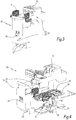
- the Figures 3 to 6 show in greater detail an example of the interconnection module 30.
- the interconnection module 30 comprises in particular power electrical conductors 31, 32 and 33, a support plate 40, an electronic card 50 and a housing 70.
- interconnection 30 further comprises a current measuring apparatus 60, a voltage sensor 80 and a data link 90, the respective role of which is described in more detail in the following.
- the electrical power conductors 31, 32 and 33 are each adapted to carry an electric current associated with an electrical phase of the supply current.
- Each of the power conductors 31, 32, 33 electrically connects a current output of a pole of the circuit breaker 10 to a corresponding current input of the contactor 20 corresponding to the same pole.
- electrical power conductor an electrical conductor capable of conducting electrical currents of intensity greater than or equal to 10 amperes, preferably of greater than or equal to 100 amps.
- the intensity of the electric currents flowing in the cable plies 6 of the data bus is at least ten times lower or one hundred times lower than the intensities of the supply electric currents.
- the electrical conductors 31, 32 and 33 are here made of an electrically conductive material, such as copper.
- each of the electrical conductors 31, 32, 33 has a flat central portion and upper and lower portions.
- the central portion has a flat plate shape.
- the upper and lower portions protrude perpendicularly from the flat plate from opposite ends of the central portion. These upper and lower portions extend on either side of the central portion parallel to each other.
- the central portions, respectively, of the electrical conductors 31, 32, 33 are denoted by 311, 321 and 331.
- the upper parts of the electrical conductors 31, 32, 33 are also marked 312, 322 and 332, and 313, 323 and 333 are noted. lower parts of the electrical conductors 31, 32, 33.
- the central portions 311, 321 and 331 extend parallel to a geometric plane P.
- connection zone 314, 324, 334 provided with a screw hole adapted to receive a connection screw, so as to form an electrical connection with another electrical connector for connecting this connection.
- each lower portion 313, 323, 333 is terminated by a connection zone provided with a screw hole 315, 325, 335 adapted to receive a connection screw, so as to form an electrical connection with another connector electrical connection for connecting this power conductor to a current output of the contactor 20.
- the electrical conductors 31, 32 and 33 are aligned with each other, so that their upper portions 312, 322 and 332 are parallel to each other and their lower portions 313, 323, 333 are parallel to each other. between them.
- the electrical conductor 32 is disposed between the electrical conductors 31 and 33.
- the power conductors 31, 32 and 33 have a similar shape, so that only their differences are described in detail in the following.
- the electrical conductors 31, 32 and 33 differ in the specific form of the connection zone 314, 324, 334 and / or connection zones 315, 325, 335. This facilitates the visual identification of the different poles and plays a function. of keying which prevents an operator, during assembly operations of the interconnection module 30, to switch the position of the electrical conductors 31, 32 and 33.
- the electrical conductors 31, 32 and 33 also differ from each other by the size of their central portion 311, 321, 331.
- the electrical conductors 31 and 33 are provided with an overwidth at their central part, respectively, 311 and 331.
- This surlargeur takes the form of a plate, respectively noted 316 and 336, integrated within the part respectively 311 and 331.
- the plates 316 and 336 are here identical and have a rectangular shape, of width "L" and length "l".
- the width L is here equal to 12 mm and the length l is here equal to 6 mm.
- the width L and the length l are measured parallel to the geometrical plane P in the mounted configuration of the module 30.
- the support plate 40 has a substantially planar shape extending along the plane P.
- This support plate 40 is made of a rigid and electrically insulating material, for example plastic, such as polyamide 6-6.
- the support plate 40 has an overmolded area 41 on the central portions 311, 321 and 331 of the electrical conductors 31, 32 and 33, on opposite sides of the opposite faces of these central portions 311, 321, 331.
- These overmoulded areas 41 make it possible to electrically isolate the electrical conductors 31, 32 and 33 partially with respect to the electronic card 50.
- the overmolded areas 41 have dimensions corresponding to the width of the central portion 311, 321, 331, in particular to take into account the plates 316 and 336 formed at the central portions 311 and 331.
- the electrical conductors 31, 32 and 33 are therefore partially integrated within the support plate 40.
- the upper portions 312, 322 and 332 and the lower portions 313, 323 and 333 project from both sides of the support plate 40. the support plate 40, as shown in FIG. figure 8 .
- the module 30 is intended to be mechanically fixed to the contactor 20.
- the module 30 comprises for example fixing devices, not shown, to attach it integrally to the housing of the contactor 20.
- the switch 20 and the interconnection module 30 thus form an electrical device.
- the housing 70 of the module 30 has a shape complementary to that of the contactor 20.
- the housing 70 has more particularly, as illustrated in FIG. figure 3 , a form comprising two main blocks joined together and extending perpendicularly in an "L-shaped" form.
- the housing 70 is for example made of molded plastic.
- one of the blocks, said front block 71, is disposed in contact with a front face of the contactor 20.
- the other block, said upper block 72, is arranged on one side upper of the switch 20.
- the electrical conductors 31, 32 and 33, the plate 40 and the electronic card 50 are housed inside the upper block 72.
- the housing 70 has a body defining a hollow housing and a cover which covers and closes the body. The assembly of this body and this cover makes it possible to obtain the two blocks 71 and 72 of the housing 70.
- the shape of the housing 70 may be different.
- connection areas 315, 325 and 335 of the upper parts 312, 322 and 332 extend outside the upper block, here through the cover.
- the module 30 includes a terminal block 73 to facilitate the connection of the connection areas 315, 325 and 335 to the corresponding current outputs of the circuit breaker 10.
- This terminal block 73 is disposed on an upper face of the block 72, The terminal block 73 is here integrated within the housing 70.
- connection module 30 When the terminal block 73 is used, the electrical connection between the connection module 30 and the circuit breaker 10 is achieved by means of dedicated electrical cables, whose respective terminal ends are connected to the power conductors, respectively 31, 32 and 33, by screwing. in the terminal block 73.
- the circuit breaker 10 can be fixed at a distance remote from the connection module 30, without having to be in contact with the housing 70. This makes it possible to adapt the use of the module 30 to a wide variety of situations, in particular according to the environment of the electrical installation 1.
- the terminal block 73 can be removably mounted relative to the housing 70.
- the terminal block 73 can be omitted.
- the connection zones 315, 325 and 335 of the electrical conductors 31, 32, 33 are directly accessible from outside the housing 70.
- the circuit breaker 10 can be fixed to the link module 30 directly by simply racking.
- the circuit breaker 10 is then in contact with the module 30.
- the module 30 mechanically connects the circuit breaker 10 to the contactor 20.
- the front portion 71 is provided with through holes 74.
- These holes 74 are arranged to open opposite corresponding holes provided on the switch 20 when the module 30 is mounted on the switch 20. These holes allow a user to passing a screwdriver through the module 30, so as to access the tightening screws of the contactor 20. These clamping screws are used to connect electrical cables to the current outputs of the contactor 20 to connect to the corresponding electric charge 4 . Thanks to this, the module 30 can be used on existing contactors, without having to modify the geometry or the architecture of these contactors 20.
- the front portion 71 is provided with a through window 75.
- the window 75 is arranged to open in front of a pre-existing window of the switch 20 when the module 30 is mounted on the switch 20.
- the switch 20 comprises a window, not shown here, which indicates the position of the separable electrical contacts and which can be used by a user to verify, mechanically, the position of the separable electrical contacts.
- the module 30 can be mounted on existing contactors 20, without having to change the geometry or architecture of these contactors 20.
- the holes 74 and / or the window 75 are omitted.
- the electronic card is provided with an electronic circuit including in particular an electronic unit 51, the role and function of which are described in the following.
- the electronic unit 51 is a programmable microcontroller.
- the electronic card 50 here comprises a printed circuit, made on a rigid insulating support, by means of electrically conductive tracks.
- the insulating support is for example a plate of epoxy resin type PCB-A for "Printed Circuit Board” in English.
- the electronic components belonging to the electronic circuit of the electronic card 50 are formed on the upper face 501.
- Electrically conductive tracks forming the printed circuits are provided on the opposite lower face 502.
- the electronic card 50 is arranged parallel to the support plate 40 and therefore parallel to the geometric plane P.
- the electronic card 50 is at least partially in contact with the plate 40.
- the electronic card 50 is provided with a plurality of through orifices, said passage orifices, allowing the passage of the upper portions 312, 322 and 332 of the electrical conductors 31, 32 and 33. In this way, when the module 30 is in an assembled configuration, each of the electrical conductors 31, 32 and 33 passes through the electronic card 50. The upper parts 312, 322 and 332 then extend perpendicularly to this electronic card 50.
- the electronic card 50 is arranged under the central portions 311, 321, 331 so that the lower portions 313, 323 and 333 of the electrical conductors 31, 32 and 33 pass through them.
- the faces 501 and 502 are permuted.
- the electronic unit 51 comprises a connection interface able to be connected with the data bus.
- the electronic card 50 has for this purpose connectors 52 and 53 fixed on the upper face 501 and connected to the electrically conductive tracks of the integrated circuit. These connectors 52 and 53 are configured to be connected to corresponding connectors, noted respectively 52 'and 53' of the ply 6.
- the connectors 52 'and 53' are formed at opposite ends of a sheet of electrical cables. flexible.
- the connectors 52 and 53 are here of different types and in particular of different size, so as to avoid unwanted swapping of the cable layers 6 forming the data bus.
- the connector 53 is accessible from outside the housing 70 of the module 30.
- the data bus allows the exchange of data between the module 30 and the outside of the assembly 3. These data are for example control signals of the actuator of the contactor 20 or signals indicating the state of the contactor 20
- the data bus also carries a power supply to the electronic card 50, for example by means of a voltage less than or equal to 24V DC.
- a copy of the cable ply 6 is connected to the electronic card 50 via the connector 52 ', the latter being received inside the corresponding connector 52.
- This connection is for example made during manufacturing operations of the module 30, before the closure of the housing 70, so that the end of the sheet 6 with the connector 53 'protrudes outside the housing 70.
- the connector 53' can then be electrically connected to a corresponding connector 53 of the module 30 of another set 3 of the installation 1 or to the central unit 2 .
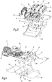
- the module 30 further comprises a current measuring device 60, which is shown in greater detail in FIGS. figures 9 , 10 and 11 .
- the measuring apparatus 60 is configured to measure the values of the electric currents flowing in the electrical conductors 31, 32 and 33.
- the measuring apparatus 60 comprises for this purpose several current sensors 61, 62, 63 of the Rogowski type, each adapted to measure the intensity values of the electric current flowing, respectively, in one of the electrical conductors 31, 32 and 33.
- Such Rogowski type sensors make it possible to determine the value of the current flowing in an electrical conductor by measuring the magnetic flux induced around this electrical conductor by the flow of electric current therein.
- the current sensors 61, 62 and 63 are here adjacent in pairs and aligned in a rectilinear manner.
- Each of the current sensors 61, 62 and 63 comprises coils 64 and 64 ', or solenoids, here identical, and a central receiving zone 61C, 62C, 63C of the corresponding electrical conductor 31, 32 and 33.
- the measuring apparatus 60 is here fixed on the upper face 501 of the electronic card 50.
- each of the electrical conductors 31, 32 and 33 is received inside the central opening 61C, 62C and 63C, respectively, of the current sensors 61, 62 and 63.
- the measuring apparatus 60 makes it possible to measure, in real time, the value of the intensity of the electric currents flowing in the electrical conductors 31, 32, 33 between the circuit breaker 10 and the contactor 20.
- the coils 64 and 64 ' are able to be electrically connected together to form a circuit for measuring the current in the corresponding conductor.
- the coils 64 and 64 ' are rectilinear and extend along longitudinal axes, respectively denoted X64 and X64'.
- Each coil 64, 64 ' here comprises a solenoid formed by winding a conductive wire with a number of turns included, for illustrative purposes, 520 turns distributed over 5 layers, with an inductance value of 0.7mH for each of coils 64, 64 '.
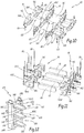
- the measuring apparatus 60 further comprises a plurality of ferromagnetic rods 65, here identical to each other, and first and second armatures, or carcasses, respectively denoted 66 and 66 ', on which the coils 64 and 64' are formed.
- the armatures 66 and 66 ' are arranged parallel to each other and are common to all the current sensors 61, 62 and 63 of the measuring apparatus 60.
- the ferromagnetic bars 65 make it possible to channel the magnetic flux generated during the passage of an electric current in the corresponding electrical conductor 31, 32, 33, so as to facilitate its measurement by the coils 64 and 64 '.
- the ferromagnetic bars 65 are made of an iron alloy, such as soft iron or NiFe nickel iron or a FeSi alloy.
- the ferromagnetic bars 65 are here four in number.
- the current sensors 61, 62 and 63 are here identical to each other, so that only the current sensor 61 is described in detail in the following, to the extent that the description which is made of them is transposable.
- the current sensor 61 comprises two of the coils 64 and 64 ', arranged parallel to each other and face to face on opposite edges of the central area 61C.
- the current sensor 61 further comprises two of the ferromagnetic rods 65. These ferromagnetic rods 65 are arranged in the same plane with the coils 64 and 64 'and extend between the ends of the coils 64 and 64' perpendicularly to the axes X64 and X64. .
- Each of the current sensors 61, 62, 63 has a ferromagnetic bar 65 which is in common with the immediately adjacent current sensor.
- the current sensor 61 has a bar 65 in common with the current sensor 62.
- the current sensor 63 has a bar 65 in common with the current sensor 62.
- the measuring apparatus 60 comprises three coils 64 and three coils 64 '.
- the measuring apparatus 60 also includes four ferromagnetic rods 65 which extend between the coils 64 and the coils 64 '.
- the coils 64, 64 'and the ferromagnetic bars 65 are arranged in the same plane parallel to the geometric plane P so as to form, for this current sensor 61, an outline polygonal, here square. This polygonal contour delimits the corresponding central opening 61C.
- the armatures 66 and 66 'each have a rectilinear shape.
- the coil which is wound around the frame 66 bears the reference 64, while the coil which is wound around the frame 66 'has the reference 64'.
- each of the armatures 66 and 66 comprises housings, or cells configured to receive an end of one of the ferromagnetic rods 65.
- the housings situated between the housings 661 bear the references 661, 662 and 663.
- the number of such housings may be different, preferably at least equal to two.
- the ferromagnetic bars are in the form of a rectangular parallelepiped shaped plate.
- each ferromagnetic bar 65 has a length of fifteen millimeters, a width of five millimeters and a thickness of two millimeters.
- the housings 661 have a shape complementary to that of the ends of the bar 65.
- the housings 661, 662 and 663 are here integrated within the frames 66 and 66 '. In fact, these housings 661, 662 and 663 here make it possible to delimit winding zones of the coils 64 and 64 '.
- These fixing elements 664 and 665 make it possible to in addition to maintaining in position the ferromagnetic bars 65.
- the fasteners 664 and 665 are carried by the housings 662 and 663.
- the fastening elements 664 and 665 are here interlocking elements of complementary shape, for example of the tenon-mortise type, allowing snap-fit casing. Alternatively, they can be made differently, for example by means of hooks.
- the intermediate housing 662 of the armature 66 carries a male type fastening element 664.
- the armatures 66 and 66 'carry fixing studs 67 which protrude from the measuring apparatus 60, perpendicular to the geometric plane P when the measuring apparatus 60 is in an assembled configuration on the electronic card 50.
- the fixing studs 67 are formed on the same side of the measuring apparatus 60, more precisely on the side of the measuring apparatus 60 which is intended to come into contact with the electronic card 50. These fixing studs 67 are intended to be received in corresponding holes, formed through the electronic card 50. This allows one hand to fix the measuring device 60 on the electronic card 50 but also to facilitate the alignment of the device measurement 60 so that the central openings 61C, 62C and 63C are located opposite the passage openings on the electronic card 50 for the passage of the electrical conductors 31, 32 and 33.
- the measuring apparatus 60 further comprises studs 68 for connecting the coils, here formed on the plates 66 and 66 ', on distal ends of the housings 661, 662 and 663.
- connection pins 68 serve the function of electrically connecting the opposite ends of each of the coils 64 and 64 'to the control unit 51, via the electrically conductive tracks of the electronic card 50, with which they are intended to be in direct electrical contact. More specifically, the ends of the wire forming the winding of each of the coils 64 and 64 'are then wound around this pin 68 so as to provide an electrical connection.
- Each connecting pin 68 is in the form of a straight rod made of an electrically conductive material, one end of which is received inside the electronic card 50, so as to provide an electrical connection with an electrical track of the electronic card. 50.
- the modular design of the measuring apparatus 60 simplifies its industrial manufacture and reduces its unit cost. Indeed, the armatures 66 and 66 'are here identical to each other and differ from each other only by their relative position within the measuring apparatus 60.
- the measuring apparatus 60 is formed by assembling head -bêche the frames 66 and 66 'with each other. Thus, the measuring apparatus 60 can be manufactured with a reduced number of pieces.
- the cost of the measuring apparatus 60 is reduced compared to existing Rogowski-type current measuring apparatus in which the entire periphery of each central opening is provided with a winding. solenoid or coil.
- the number of coils 64, 64 'necessary for each of the current sensors 61, 62 and 63 is equal to two, which is less than in known Rogowswki-type current sensors where at least four such coils are needed.
- the measuring apparatus 60 may be manufactured industrially as follows.
- an armature 66 or 66 ' is acquired. This armature 66 or 66 'is previously provided with connection pins 68.
- coils 64 are formed by winding on winding areas of the frame 66, for example by means of an automatic winding machine.
- the conductive wire is first wound around one of the connection pins 68, with one turn, then is surrounded repeatedly around a first winding zone of the armature 66 to form a first coil 64.
- this wire is wrapped around another connecting pin of the armature 66.
- the wire is then cut and the operation is repeated, similarly, for each of the winding zones of the armature 66.
- the coils are formed in a simplified manner around the frame 66.
- the measuring apparatus 60 is assembled.
- the armatures 66 and 66 'provided with the coils 64 and 64' are joined opposite one another. Ferromagnetic bars 65 are inserted in each of the housings 661, 662 and 663 of the armature 66.
- the armature 66 is fixed on the armature 66 'by inserting the opposite end of each of the ferromagnetic rods 65 into the housings 661. , 662 and 663 corresponding to the armature 66.
- the fasteners 664 and 665 are then inserted into one another and then snap-fastened so as to secure these armatures 66 and 66 '.
- the measuring apparatus 60 is then ready to be mounted on the electronic board 50.
- the figure 12 illustrates another embodiment of the measuring apparatus 60.
- the current meter according to this embodiment is "600".
- This measuring device 600 is particularly suitable for a variant of the connection module 30, in which the electrical conductors 31, 32 and 33 are replaced by electrical power conductors 310, 320 and 330 which are superimposed with each other.
- the measuring apparatus 600 comprises ferromagnetic bars which bear a reference 650 and which are similar to the ferromagnetic bars 65 of the measuring apparatus 60.
- the bars 650 are here two in number.
- the measuring apparatus 600 differs from the measuring apparatus 60 in particular in that the armatures 660 and 660 'each comprise a rectilinear main part and branch-shaped abutments projecting from the main part. perpendicular to the main part.
- the armatures 660 and 660 'each comprise three secondary parts which extend on the same side of the main part so that these armatures have an E-shape.
- the coils 84 are thus formed on the parts. Secondary coils protruding from the frame 660.
- Each main part of the frames 660 and 660 ' has a recess extending over the entire length of the main part and inside which is received one of the ferromagnetic bars 650.
- the armatures 660 and 660 ' can be assembled together with the electrical conductors 310, 320 and 330.
- the Figures 13 and 14 show in more detail the voltage sensor 80.
- the voltage sensor 80 is intended to detect the presence of an electrical potential difference between two of the electrical conductors 31, 32 and 33, here between the electrical conductors 31 and 33. This indirectly allows to know the state of the circuit breaker 10 and to know, in particular, whether this breaker is in an open or closed state.
- the electronic unit 51 is further configured to generate a signal representative of the state of the circuit breaker 10 by means of the supplied data of the voltage sensor 80.
- the voltage sensor comprises at least one electrically conductive plate, or electric field sensor, arranged at a distance and facing one of the plates 316, 326 or 336 of the electrical conductors 31, 32 and 33, respectively.
- the presence or, alternatively, the absence of an electrical voltage is determined indirectly, as a function of the value of the electrical capacitance between these plates by means of a dedicated measuring circuit 84.
- the detector 80 here comprises two such plates 81 and 83, made of a conductive material and extending parallel to the geometric plane P.
- the plate 81 faces the plate 316 while being aligned with this plate 316.
- the plate 83 faces the plate 336 in alignment with this plate 336.
- These plates 81 and 83 are formed on the face 502 of the electronic card 50, for example by depositing a copper metal track.
- the plates 81 and 83 have identical dimensions to the plates, respectively, 316 and 336, within 5% or preferably to 1%.
- the plates 81 and 83 are here surfaces or surfaces identical to each other.
- the plates 81 and 316 are separated from each other by the molded part 41 and are in contact with this overmoulded portion 41. The same is true with the plates 83 and 336, respectively.
- d the distance between the plates 81 and 316, measured in a direction perpendicular to the geometric plane P.
- This distance d is equal to the thickness of the overmolded portion 41 which covers an upper face of the plate 316.
- the distance d is chosen so as to bring the plate 81 as close as possible to the plate 316, without compromising the electrical insulation function of the power conductor 31 provided by the overmoulded part 41.
- the distance d is preferably less than or equal to 2 mm, more preferably between 0.5 mm and 1 mm and, even more preferably, between 0.65 mm and 0.85 mm. By way of illustration, the distance d here is equal to 0.8 mm.
- the plates 83 and 336 are also spaced from each other by the distance d.
- C1 denotes the capacitor formed by the plates 81 and 316 and C2 the capacitor formed by the plates 83 and 336.
- the respective capacitances of the capacitors C1 and C2 are here equal, taking into account the dimensions and relative provisions of the plates 81, 83 , 316 and 336.
- the value of the capacitance of the capacitor C1 is equal to ( ⁇ x S) / d, where S is the area of the plates 81 and 316 facing each other and " ⁇ " is the electrical permittivity of the material forming the
- the area S is here equal to the product of the length L by the width l, insofar as the plates 81 and 316 are identical and face to face with each other. Given the numerical values indicated above, the area S is here equal to 74 mm 2 .
- the capacitor C1 has a capacitance value of between 2.8pF and 4.4pF when the distance d is between 0.65mm and 0.85mm. The person skilled in the art knows that the capacitance value of the capacitor C1 is inversely proportional to the distance d.
- the sensor 80 also comprises a measuring circuit 84, which includes the plates 81 and 83 and a measuring resistor 801 whose ends are connected on the one hand to the plate 81 and on the other hand to the plate 83.
- measuring circuit 84 is adapted to acquire a measurement voltage Vm across the measuring resistor 801.
- the measuring circuit 84 advantageously comprises a bidirectional Zener diode 802, which protects the measuring circuit 84 against overvoltages, in particular likely to occur when the electrical installation 1 or its power supply source is struck by lightning.
- the measuring circuit 83 is connected to an input of the electronic unit 51 by means of an analog-to-digital converter, not shown.
- the measuring circuit 83 also comprises a low-pass filter 803 configured to pass frequencies belonging to the 45Hz-65Hz interval.
- the filter 803 makes it possible to avoid saturation of the input of the analog-digital converter, which could lead to a malfunction of the sensor 80.
- Such a filter 803 makes it possible in particular to filter the harmonics of the electric supply current which could disturb the measurement of the circuit 83.
- the power supply current of the assembly 3 has a frequency equal to 50 Hz or 60 Hz.
- the sensor 80 finally has a ground plane 82, formed on the face 502 and connected to a GND electrical ground of the measuring circuit 84, so as to provide protection of the device 80 against electromagnetic disturbances.
- This ground plane 82 is made by depositing a metal layer on the face 502, on an area placed facing the area occupied by the current sensor 61.
- the detection of the presence of an electrical voltage is carried out by the voltage sensor 80 between the electrical conductors 31 and 33.
- the measurement voltage Vm at the terminals of the resistor 501 is equal to a value which depends on the voltage Vp and the capacitance value of the capacitors C1 and C2.
- the voltage Vm is equal to 150mV.
- the voltage Vm is equal to 62mV.
- the unit 51 is programmed to measure the measurement voltage supplied by the measuring circuit 84, for example continuously or at times repeated over time, and to generate a corresponding state signal as a function of the measurement voltage. Vm acquired. The unit 51 then sends this status signal to the data bus, for example at a predetermined time or in response to a request issued by the central unit 2.
- the electronic unit 51 automatically determines that no electrical voltage is present between the electrical conductors 31 and 33 if the measured voltage Vm remains permanently zero, for example for more than ten times the duration of the frequency of the electric current feeding, preferably more than a hundred times. The electronic unit 51 determines that an electrical voltage is present between the electrical conductors 31 and 33 in the opposite case.
- Such a voltage sensor 80 makes it possible to detect the presence or, alternatively, the absence of an electric voltage and thus to extrapolate the state of the circuit breaker 10 of the assembly 3 to which the module 30 belongs, without the need for need to physically access the circuit breaker 10. This detection is performed without direct electrical contact with the electrical conductors 31, 32 and 33. It is therefore not necessary to equip the voltage sensor 80 with a galvanic isolation, which is more expensive and more complex to integrate. The accuracy of the measurement is not an obstacle to the proper functioning of the voltage sensor 80, because here it is mainly desired to know if an electric voltage Vp is present or not between the power conductors 31 and 33, and not necessarily to obtain a precise value of this voltage.
- the voltage sensor 80 may be made differently, for example by replacing the plates 81 and 83 by a single electric field sensor disposed opposite one of the central portions 311, 321 or 331.
- the voltage sensor 80 is replaced by a voltage sensor comprising a divider bridge directly connected to the electrical conductors 31, 32 and 33. In this case, a galvanic isolation is necessary.
- the Figures 15 and 16 represent the data link 90 between the module 30 and the switch 20.
- This data link 90 is adapted to transmit an opening or closing control signal of the switch 20.
- This data link 90 is also adapted to collect one or several signals for measuring the state of the contactor 20.
- This device 90 is adapted to connect to a corresponding signal input / output interface of the contactor 20.
- the link 90 comprises a connector 91 and pairs of wires 92, 93 and 94.
- the connector 91 is adapted to be connected to the electronic card 50.
- the connector 91 is here fixed to the card 50, one end of this electronic card 50.
- the link 90 comprises a rigid armature on which the pairs of wires 92, 93 and 94 are mounted.
- this armature is made of plastic molded onto the pairs of wires 92, 93 and 94. This facilitates assembly of the module. 30 on the switch 20, including reducing the space occupied by the son 92, 93 and 94.
- This frame can be omitted.
- the connector 91 has several openings each for receiving one of the son of the son pairs 92, 93 or 94, so as to electrically connect them to corresponding electrical tracks of the printed circuit of the electronic card 50.
- the wires of the pair of wires 92 are intended to electrically power the actuator of the contactor 20.
- the pair of wires 93 is configured to collect the state signal NO from a corresponding output interface of the contactor 20.
- the wires of the pair of wires 94 are adapted to collect the NC state signal from the corresponding output interface of the contactor 20.
- one of the terminals associated with the wire 92 is common with one of the terminals associated with the wire 93. This is for example due to the fact that the corresponding signals are generated with respect to a common electrical ground within the electrical contact 20. Alternatively, these two son can be distinct from each other.
- the figure 16 represents another embodiment of the link 90.
- This data link, denoted 90 ', is similar to the link 90, but differs in that the pair of wires 94 is omitted. This is useful in applications for which it is not necessary to know the NC status signal.
- the module 30 makes it possible, thanks to the measuring apparatus 60, to the voltage sensor 80 and to the electronic unit 51, to collect real-time information on the operating state of the circuit breaker 10 and the contactor 20, and to order these, according to this information and / or from the central unit 2, in an improved manner.
- the electrical assembly 3 has advanced communication and control functions, without it being necessary to change the architecture or the operation of the circuit breaker 10 or the contactor 20.
- the module 30 thus allows add new functionalities to existing product lines, or even to circuit breakers and / or contactors already installed on an existing electrical installation.
Abstract
Appareil de mesure (60) de courants électriques comportant plusieurs capteurs de courant (61, 62, 63) de type Rogowski, chacun adapté pour mesurer un courant électrique circulant dans un conducteur électrique, ces capteurs de courant étant adjacents deux à deux et comportant chacun des bobines (64, 64') de mesure du courant et une ouverture centrale (61C, 62C, 63C) de réception du conducteur électrique correspondant. Chaque capteur de courant (61, 62, 63) comporte deux desdites bobines (64, 64'), disposées parallèlement et face à face sur des bords opposés de l'ouverture centrale (61C, 62C, 63C) et deux barreaux ferromagnétiques (65) s'étendant entre des extrémités des bobines (64, 64'), perpendiculairement à un axe longitudinal (X64, X64') des bobines, chaque capteur de courant (61, 62, 63) présentant un barreau ferromagnétique (65) en commun avec le capteur de courant immédiatement adjacent.Electrical current measuring apparatus (60) comprising a plurality of Rogowski type current sensors (61, 62, 63), each adapted to measure an electric current flowing in an electrical conductor, these current sensors being adjacent in pairs and each comprising current measuring coils (64, 64 ') and a central opening (61C, 62C, 63C) for receiving the corresponding electrical conductor. Each current sensor (61, 62, 63) comprises two of said coils (64, 64 '), arranged parallel and face to face on opposite edges of the central opening (61C, 62C, 63C) and two ferromagnetic bars (65 ) extending between ends of the coils (64, 64 '), perpendicular to a longitudinal axis (X64, X64') of the coils, each current sensor (61, 62, 63) having a ferromagnetic bar (65) in common with the immediately adjacent current sensor.
Description
La présente invention concerne un appareil de mesure de courants électriques.The present invention relates to an apparatus for measuring electric currents.
On connait des ensembles électriques destinés à commander l'alimentation électrique d'une charge électrique et d'assurer une protection de cette charge électrique. Par exemple, on connaît des ensembles de départ moteur pour piloter des moteurs électriques industriels, tels que des moteurs asynchrones.Electrical assemblies are known for controlling the electrical supply of an electric charge and for providing protection for this electric charge. For example, motor starting assemblies are known for controlling industrial electric motors, such as asynchronous motors.
Un tel ensemble électrique comporte typiquement, pour chaque charge électrique, un disjoncteur et un contacteur qui commandent l'alimentation électrique de cette charge électrique. Le disjoncteur, placé en amont, assure une protection de l'alimentation électrique contre des anomalies, telles que des court-circuits ou des surintensités. Le contacteur, placé en aval, permet d'interrompre sélectivement l'alimentation de la charge électrique, en réponse à un signal de commande. Le module d'interconnexion raccorde électriquement entre eux une sortie de puissance du disjoncteur avec une entrée de puissance du contacteur. Un tel module d'interconnexion est par exemple décrit dans
Lorsque plusieurs charges électriques sont utilisées, il est d'usage de mettre en oeuvre plusieurs ensembles de départ moteur connectés entre eux en parallèle, chacun alimentant électriquement une charge. Ces ensembles électriques peuvent être interconnectés entre eux au moyen d'un bus de données, qui permet d'échanger de l'information entre chacun des ensembles électriques et une unité centrale de commande. Par exemple, ce bus de données permet de transmettre un signal de commande à destination d'un contacteur, ou encore de mesurer l'état de chaque contacteur à un instant donné pour effectuer des diagnostics à distance. Un exemple d'un tel bus de données est décrit dans la demande
Dans de tels ensembles électriques, il est souhaitable de connaître la valeur du courant électrique qui circule entre le disjoncteur et le contacteur, notamment pour détecter indirectement des défauts thermiques, par exemple un échauffement anormal dû à une surintensité.In such electrical assemblies, it is desirable to know the value of the electric current flowing between the circuit breaker and the contactor, in particular to indirectly detect thermal defects, for example abnormal heating due to overcurrent.
On connaît des capteurs de courant aptes à mesurer de tels courants électriques. Mais ils sont généralement encombrants et leur réalisation à une échelle industrielle est coûteuse et complexe.Current sensors capable of measuring such electric currents are known. But they are generally bulky and their realization on an industrial scale is expensive and complex.
C'est à ces inconvénients qu'entend plus particulièrement remédier l'invention, en proposant un appareil de mesure de courants électriques qui soit compact et qui présente un coût unitaire réduit et qui dont la fabrication industrielle soit simplifiée.It is these drawbacks that the invention intends to remedy more particularly by proposing an apparatus for measuring electric currents which is compact and which has a reduced unit cost and whose industrial manufacture is simplified.
A cet effet, l'invention a pour objet un appareil de mesure de courants électriques dans un circuit électrique, cet appareil comportant plusieurs capteurs de courant de type Rogowski, chacun adapté pour mesurer un courant électrique circulant dans un conducteur électrique, ces capteurs de courant étant adjacents deux à deux et comportant chacun :
- des bobines aptes à être raccordées électriquement entre elles pour former un circuit de mesure du courant,
- une ouverture centrale de réception du conducteur électrique correspondant, les bobines étant disposées sur le pourtour de l'ouverture centrale,
- coils adapted to be electrically connected together to form a current measuring circuit,
- a central opening for receiving the corresponding electrical conductor, the coils being disposed around the periphery of the central opening,
Grace à l'invention, on dispose d'un moyen fiable et compact pour mesurer les courants qui circulent dans des conducteurs électriques. La construction modulaire de l'appareil de mesure le rend plus facile et moins coûteux à fabriquer à une échelle industrielle.Thanks to the invention, there is a reliable and compact means for measuring the currents flowing in electrical conductors. The modular construction of the meter makes it easier and less expensive to manufacture on an industrial scale.
Selon des modes de réalisation avantageux mais non obligatoires de l'invention, le module d'interconnexion peut comporter l'une ou l'autre des caractéristiques suivantes, prises selon toute combinaison techniquement admissible, dans lesquelles :
- Chaque capteur de courant présente un barreau ferromagnétique en commun avec le capteur de courant immédiatement adjacent.
- L'appareil comporte des première et deuxième armatures disposées parallèlement entre elles et communes à tous les capteurs de courant de l'appareil, les deux bobines de chaque capteur de courant étant respectivement ménagées sur les première et deuxième armatures.
- Chacune des première et deuxième armatures présente une partie rectiligne, les bobines étant ménagées sur ces première et deuxième armatures par enroulement autour de cette partie rectiligne.
- Chacune des première et deuxième armatures comporte des logements adaptés pour recevoir chacun une extrémité d'un des barreaux ferromagnétiques.
- Les première et seconde armatures sont identiques et comportent chacune des éléments de fixation, adaptés pour solidariser l'une à l'autre les première et deuxième armatures pour former l'appareil de mesure.
- Les première et deuxième armatures comportent chacune une partie principale de forme rectiligne et des parties secondaires qui s'étendent en saillie depuis la partie principale perpendiculairement à la partie principale, les bobines étant ménagées par enroulement sur les première et deuxième armatures au niveau des parties secondaires.
- La partie principale de chacune des première et deuxième armatures comporte un évidement à l'intérieur duquel est reçu un des barreaux ferromagnétiques, cet évidement s'étendant selon la longueur de la partie principale.
- Each current sensor has a ferromagnetic bar in common with the immediately adjacent current sensor.
- The apparatus comprises first and second armatures arranged parallel to each other and common to all the current sensors of the apparatus, the two coils of each current sensor being respectively provided on the first and second armatures.
- Each of the first and second armatures has a rectilinear part, the coils being formed on these first and second armatures by winding around this rectilinear part.
- Each of the first and second armatures comprises housings adapted to each receive one end of one of the ferromagnetic bars.
- The first and second armatures are identical and each comprise fixing elements, adapted to secure to one another the first and second armatures to form the measuring apparatus.
- The first and second armatures each comprise a main portion of rectilinear shape and secondary portions which project from the main part perpendicularly to the main part, the coils being formed by winding on the first and second armatures at the abutments. .
- The main part of each of the first and second armatures comprises a recess inside which is received one of the ferromagnetic bars, this recess extending along the length of the main part.
Selon un autre aspect, l'invention concerne un appareil de mesure tel que décrit précédemment, caractérisé en ce que les barreaux ferromagnétiques sont réalisés en un alliage de fer, tel que du fer doux ou du NiFe ou du FeSi.According to another aspect, the invention relates to a measuring apparatus as described above, characterized in that the ferromagnetic bars are made of an iron alloy, such as soft iron or NiFe or FeSi.
Selon un autre aspect, l'invention concerne un ensemble comportant un dispositif électrique, alimenté électriquement par des conducteurs électriques et un appareil de mesure, adapté pour mesurer le courant électrique qui circule au travers de chacun des conducteurs électriques. Conformément à l'invention, l'appareil de mesure est tel que décrit ci-dessus, chacun des conducteurs électriques étant reçu à l'intérieur de la zone centrale de réception du capteur de courant correspondant.According to another aspect, the invention relates to an assembly comprising an electrical device, electrically powered by electrical conductors and a measuring device, adapted to measure the electric current flowing through each of the electrical conductors. According to the invention, the measuring apparatus is as described above, each of the electrical conductors being received within the central receiving area of the corresponding current sensor.
L'invention sera mieux comprise et d'autres avantages de celle-ci apparaîtront plus clairement à la lumière de la description qui va suivre, d'un mode de réalisation d'un module d'interconnexion, donné uniquement à titre d'exemple et faite en référence aux dessins annexés dans lesquels:
- la
figure 1 est une représentation schématique d'une installation électrique comportant un ensemble électrique pourvu d'un module d'interconnexion selon l'invention ; - la
figure 2 représente schématiquement, selon une vue en perspective éclatée, un ensemble électrique de lafigure 1 comportant un disjoncteur, un contacteur et un module d'interconnexion selon l'invention ; - les
figures 3 et 4 représentent schématiquement le module d'interconnexion desfigures 1 et 2 , respectivement dans une configuration assemblée et dans une vue éclatée ; - les
figures 5 et 6 représentent schématiquement, selon, respectivement, une vue de dessus et de dessous, une carte électronique du module d'interconnexion de lafigure 2 ; - la
figure 7 représente schématiquement, selon une vue rapprochée, des conducteurs électriques de puissance du module d'interconnexion de lafigure 2 ; - la
figure 8 est une vue schématique en coupe longitudinale de la carte électronique desfigures 5 et 6 ; - les
figures 9 et10 représentent schématiquement, selon des vues en perspective, un appareil de mesure du courant circulant au travers des conducteurs électriques de puissance de lafigure 7 ; - la
figure 11 représente schématiquement, selon une vue éclatée, l'appareil de mesure de courant desfigures 9 et10 ; - la
figure 12 représente schématiquement un autre mode de réalisation de l'appareil de mesure de courant desfigures 8 à 10 ; - la
figure 13 représente schématiquement, selon une vue en coupe, un capteur de tension électrique équipant le module d'interconnexion de lafigure 2 ; - la
figure 14 représente schématiquement un schéma électrique du capteur de tension de lafigure 13 . - les
figures 15 et 16 représentent schématiquement deux modes de réalisation d'une liaison de données entre le module d'interconnexion et le contacteur de lafigure 2 .
- the
figure 1 is a schematic representation of an electrical installation comprising an electrical assembly provided with an interconnection module according to the invention; - the
figure 2 schematically shows, according to an exploded perspective view, an electrical assembly of thefigure 1 comprising a circuit breaker, a contactor and an interconnection module according to the invention; - the
Figures 3 and 4 schematically represent the interconnection module of theFigures 1 and 2 respectively in an assembled configuration and in an exploded view; - the
Figures 5 and 6 schematically, according to, respectively, a view from above and from below, an electronic card of the interconnection module of thefigure 2 ; - the
figure 7 schematically shows, in a close-up view, the electrical power conductors of the interconnection module of thefigure 2 ; - the
figure 8 is a schematic view in longitudinal section of the electronic map of theFigures 5 and 6 ; - the
figures 9 and10 schematically represent, in perspective views, a device for measuring the current flowing through the electrical power conductors of thefigure 7 ; - the
figure 11 schematically shows, in an exploded view, the current measuring apparatus offigures 9 and10 ; - the
figure 12 schematically represents another embodiment of the current measuring apparatus ofFigures 8 to 10 ; - the
figure 13 represents schematically, in a sectional view, a voltage sensor fitted to the interconnection module of thefigure 2 ; - the
figure 14 schematically represents a circuit diagram of the voltage sensor of thefigure 13 . - the
Figures 15 and 16 schematically represent two embodiments of a data link between the interconnection module and the contactor of thefigure 2 .
La
Dans cet exemple, les charges électriques 4 sont des moteurs électriques industriels, tels que des moteurs asynchrones.In this example, the
Pour simplifier la
Chacun des ensembles électriques 3 est adapté pour commander l'alimentation électrique d'une charge électrique 4. Plus précisément, chacun des ensembles électriques 3 est intercalé entre une source d'énergie électrique, non illustrée, et une des charges électriques 4. Les ensembles électriques 3 sont ainsi adaptés pour à réguler l'alimentation électrique de cette charge électrique 4, par exemple pour activer ou désactiver sélectivement l'alimentation de la charge électrique correspondante 4. Dans cet exemple, la source d'énergie électrique fournit un courant électrique d'alimentation, ici alternatif et triphasé.Each of the
Comme illustré à la
Le disjoncteur 10 est adapté pour interrompre, en cas d'anomalie ou d'un défaut de sécurité, la circulation du courant électrique en provenance de la source d'alimentation. Ce défaut est par exemple une surintensité ou un court-circuit.The
Le disjoncteur 10 est ici un disjoncteur multipolaire, pourvu d'une pluralité de pôles électriques, chacun associé à une phase électrique du courant électrique d'alimentation. Par exemple, le disjoncteur 10 comporte, pour chaque pôle, une entrée et une sortie de courant raccordée entre elles par des contacts électriques séparables internes au disjoncteur 10. Ces contacts électriques sont commutables entre des états ouvert ou fermé, de manière à, respectivement, interrompre ou autoriser le passage d'un courant entre l'entrée et la sortie de courant. Cette commutation est réalisée automatiquement, par un circuit de détection d'un défaut électrique, en cas d'une anomalie telle qu'une surintensité ou un court-circuit.The
Les entrées de courant du disjoncteur 10 sont raccordées à la source d'énergie électrique.The current inputs of the
Le contacteur 20 est adapté pour interrompre ou, en alternance, autoriser la circulation du courant électrique provenant en sortie du disjoncteur 10, à destination de la charge électrique 4 correspondante, ceci en fonction d'un signal de commande délivré par l'unité centrale 2.The
Le contacteur 20 est ici un contacteur multipolaire, pourvu d'une pluralité de pôles électriques, chacun associé à une phase électrique du courant électrique d'alimentation. Par exemple, le disjoncteur 20 comporte, pour chaque pôle, une entrée et une sortie de courant raccordées entre elles par des contacts électriques séparables internes au contacteur 20. Ces contacts électriques sont sélectivement déplaçables entre des positions ouverte et fermée, dans lesquelles ils inhibent ou, respectivement, autorisent la circulation d'un courant électrique entre l'entrée et la sortie de courant du contacteur 20. Ce déplacement est réalisé au moyen d'un actionneur interne au contacteur 20, en réponse au signal de commande. Cet actionneur comporte par exemple un électroaimant.The
Le contacteur 20 comporte également des capteurs de mesure de l'état des contacts électriques séparables. En particulier, ces capteurs sont configurés pour fournir un premier signal d'état indiquant que les contacts sont dans un état normalement fermé, dit signal d'état « NC », pour « normally closed » en langue anglaise. Ces capteurs sont également configurés pour fournir un deuxième signal d'état indiquant que les contacts sont dans un état ouvert, dit signal d'état « NO », pour « normally open » en langue anglaise. Ces signaux d'état permettent d'établir un diagnostic de l'état du contacteur 20.The
Les sorties de courant du contacteur 20 sont raccordées électriquement à la charge électrique 4 correspondante pour alimenter cette charge électrique 4 avec le courant électrique d'alimentation.The current outputs of the
L'unité centrale 2 est notamment configurée pour commander sélectivement chacun des contacteurs 20 et pour collecter des informations sur l'état de chacun des contacteurs 20 fourni par chacun de ces contacteurs 20. A cet effet, l'installation 1 comporte un bus de données qui raccorde les différents ensembles électriques 3 à l'unité centrale 2. Ce bus de données est ici réalisé en connectant les ensembles électriques 3 en série, ici deux à deux, au moyen de nappes 6 de câbles, comme expliqué plus en détail dans ce qui suit.The central unit 2 is notably configured to selectively control each of the
Le module d'interconnexion 30 relie électriquement les sorties de courant du disjoncteur 10 aux entrées de courant correspondantes du contacteur 20. En outre, le module d'interconnexion 30 est apte à mesurer des grandeurs physiques représentatives du courant électrique qui circule du disjoncteur 10 vers le contacteur 20, comme expliqué plus en détail dans ce qui suit. Le module 30 est ici destiné à être placé au-dessus du contacteur 20 et en-dessous du disjoncteur 10.The
Les
Les conducteurs électriques de puissance 31, 32 et 33 sont chacun adaptés pour transporter un courant électrique associé à une phase électrique du courant d'alimentation. Chacun des conducteurs de puissance 31, 32, 33 raccorde électriquement une sortie de courant d'un pôle du disjoncteur 10 à une entrée correspondante de courant du contacteur 20 correspondant à ce même pôle.The
Par « conducteur électrique de puissance », on désigne un conducteur électrique apte à conduire des courants électriques d'intensité supérieure ou égale à 10 Ampères, de préférence d'intensité supérieure ou égale à 100 Ampères. Par comparaison, l'intensité des courants électriques qui circulent dans les nappes de câbles 6 du bus de données est au moins dix fois inférieure ou cent fois inférieure aux intensités des courants électriques d'alimentation.By "electrical power conductor" is meant an electrical conductor capable of conducting electrical currents of intensity greater than or equal to 10 amperes, preferably of greater than or equal to 100 amps. By comparison, the intensity of the electric currents flowing in the cable plies 6 of the data bus is at least ten times lower or one hundred times lower than the intensities of the supply electric currents.
Les conducteurs électriques 31, 32 et 33 sont ici réalisés en un matériau électriquement conducteur, tel que du cuivre.The
Comme illustré à la
On note 311, 321 et 331 les parties centrales, respectivement, des conducteurs électriques 31, 32, 33. On note également 312, 322 et 332 les parties supérieures des conducteurs électriques 31, 32, 33 et on note 313, 323 et 333 les parties inférieures des conducteurs électriques 31, 32, 33.The central portions, respectively, of the
Dans une configuration montée du module 30, les parties centrales 311, 321 et 331 s'étendent parallèlement à un plan géométrique P.In an assembled configuration of the
Chaque partie supérieure 312, 322 et 332 est terminée par une zone de raccordement 314, 324, 334 pourvue d'un trou de vissage adapté pour recevoir une vis de connexion, de manière à former une liaison électrique avec un autre connecteur électrique pour raccorder ce conducteur de puissance à une sortie de courant du disjoncteur 10.Each
De façon analogue, chaque partie inférieure 313, 323, 333 est terminée par une zone de raccordement pourvue d'un trou de vissage 315, 325, 335 adapté pour recevoir une vis de connexion, de manière à former une liaison électrique avec un autre connecteur électrique pour raccorder ce conducteur de puissance à une sortie de courant du contacteur 20.Similarly, each
Dans une configuration montée du module 30, les conducteurs électriques 31, 32 et 33 sont alignés entre eux, de manière à ce que leurs parties supérieures 312, 322 et 332 soient parallèles entre elles et que leurs parties inférieures 313, 323, 333 soient parallèles entre elles. Le conducteur électriques 32 est disposé entre les conducteurs électriques 31 et 33.In an assembled configuration of the
Dans cet exemple, les conducteurs de puissance 31, 32 et 33 présentent une forme similaire, de sorte que seules leurs différences sont décrites en détail dans ce qui suit.In this example, the
Avantageusement, les conducteurs électriques 31, 32 et 33 diffèrent par la forme spécifique de la zone de raccordement 314, 324, 334 et/ou des zones de raccordement 315, 325, 335. Cela facilite le repérage visuel des différents pôles et joue une fonction de détrompage qui évite à un opérateur, lors d'opérations de montage du module d'interconnexion 30, de permuter la position des conducteurs électriques 31, 32 et 33.Advantageously, the
Les conducteurs électriques 31, 32 et 33 diffèrent également les uns des autres par la dimension de leur partie centrale 311, 321, 331.The
En particulier, les conducteurs électriques 31 et 33 sont pourvus d'une surlargeur au niveau de leur partie centrale, respectivement, 311 et 331. Cette surlargeur prend la forme d'une plaque, respectivement notée 316 et 336, intégrée au sein de la partie centrale, respectivement 311 et 331.In particular, the
Les plaques 316 et 336 sont ici identiques et présentent une forme rectangulaire, de largeur « L » et de longueur « l ». A titre d'exemple illustratif, la largeur L est ici égale à 12mm et la longueur l est ici égale à 6mm. La largeur L et la longueur l sont mesurées parallèlement au plan géométrique P dans la configuration montée du module 30.The
La plaque de support 40 présente une forme essentiellement plane s'étendant selon le plan P. Cette plaque de support 40 est réalisée dans un matériau rigide et électriquement isolant, par exemple en matière plastique, telle que du polyamide 6-6.The
La plaque de support 40 comporte une zone surmoulée 41 sur les parties centrales 311, 321 et 331 des conducteurs électriques 31, 32 et 33, de part et d'autre des faces opposées de ces parties centrales 311, 321, 331. Ces zones surmoulées 41 permettent d'isoler électriquement les conducteurs électriques 31, 32 et 33 partiellement par rapport à la carte électronique 50. Les zones surmoulées 41 présentent des dimensions correspondantes à la largeur de la partie centrale 311, 321, 331, notamment pour tenir compte des plaques 316 et 336 ménagées au niveau des parties centrales 311 et 331.The
Les conducteurs électriques 31, 32 et 33 sont donc partiellement intégrés au sein de la plaque de support 40. Les parties supérieures 312, 322 et 332 et les parties inférieures 313, 323 et 333 s'étendent en saillie de part et d'autre de la plaque de support 40, comme illustré à la
Ainsi, grâce à la plaque de support 40 et aux zones surmoulées 41, une isolation électrique est assurée entre les conducteurs électriques 31, 32 et 33 et la carte électronique 50.Thus, thanks to the
Dans cet exemple, le module 30 est destiné à être fixé mécaniquement au contacteur 20. Le module 30 comporte par exemple des dispositifs de fixation, non illustrés, pour l'attacher solidairement au boîtier du contacteur 20.In this example, the
Dans une configuration montée, comme visible à la
Le boîtier 70 présente plus particulièrement, comme illustré à la
Dans une configuration montée du module 30 sur le contacteur 20, l'une des blocs, dite bloc avant 71, est disposée en contact avec une face avant du contacteur 20. L'autre bloc, dit bloc supérieur 72, est disposé sur une face supérieure du contacteur 20. Les conducteurs électriques 31, 32 et 33, la plaque 40 et la carte électronique 50 sont logés à l'intérieur du bloc supérieur 72.In an assembled configuration of the
Le boîtier 70 comporte un corps délimitant un logement creux et un couvercle qui recouvre et ferme le corps. L'assemblage de ce corps et de ce couvercle permet d'obtenir les deux blocs 71 et 72 du boîtier 70.The
En variante, la forme du boîtier 70 peut être différente.Alternatively, the shape of the
Dans une configuration assemblée du module 30, les zones de raccordement 315, 325 et 335 des parties supérieures 312, 322 et 332 s'étendent à l'extérieur du bloc supérieur, ici au travers du couvercle.In an assembled configuration of the
Ici, le module 30 comporte un bornier 73 pour faciliter la connexion des zones de raccordement 315, 325 et 335 aux sorties correspondantes de courant du disjoncteur 10. Ce bornier 73 est disposé sur une face supérieure du bloc 72, Le bornier 73 est ici intégré au sein du boîtier 70.Here, the
Lorsque le bornier 73 est utilisé, le raccordement électrique entre le module de liaison 30 et le disjoncteur 10 est réalisé au moyen de câbles électriques dédiés, dont des extrémités terminales respectives sont connectées aux conducteurs de puissance, respectivement 31, 32 et 33, par vissage dans le bornier 73. Ainsi, le disjoncteur 10 peut être fixé à une distance éloignée du module de liaison 30, sans devoir impérativement être en contact avec le boîtier 70. Cela permet d'adapter l'utilisation du module 30 à une grande variété de situations, notamment en fonction de l'environnement de l'installation électrique 1.When the
En variante, le bornier 73 peut être monté de façon amovible par rapport au boîtier 70.Alternatively, the
Selon encore une autre variante, le bornier 73 peut être omis. Lorsque le bornier 73 est omis, les zones de raccordement 315, 325 et 335 des conducteurs électriques 31, 32, 33 sont directement accessibles depuis à l'extérieur du boîtier 70. De cette façon, le disjoncteur 10 peut être fixé au module de liaison 30 directement par simple embrochage. Le disjoncteur 10 est alors en contact avec le module 30. Dans ce cas, le module 30 raccorde donc mécaniquement le disjoncteur 10 au contacteur 20.According to yet another variant, the
Avantageusement, la partie avant 71 est pourvue de trous traversants 74. Ces trous 74 sont agencés de sorte à déboucher en face de trous correspondants ménagés sur le contacteur 20 lorsque le module 30 est monté sur le contacteur 20. Ces trous permettent à un utilisateur de faire passer un tournevis au travers du module 30, de manière à accéder à des vis de serrage du contacteur 20. Ces vis de serrage sont utilisés pour connecter des câbles électriques aux sorties de courant du contacteur 20 pour le raccorder à la charge électrique 4 correspondante. Grâce à cela, le module 30 peut être utilisé sur des contacteurs 20 existants, sans avoir à modifier la géométrie ou l'architecture de ces contacteurs 20.Advantageously, the
De façon optionnelle, la partie avant 71 est pourvue d'une fenêtre traversante 75. La fenêtre 75 est agencée de sorte à déboucher en face d'une fenêtre préexistante du contacteur 20 lorsque le module 30 est monté sur la contacteur 20. En effet, le contacteur 20 comporte une fenêtre, ici non illustrée, qui indique la position des contacts électriques séparables et qui peut être utilisée par un utilisateur pour vérifier, de façon mécanique, la position des contacts électriques séparables. Là encore, le module 30 peut être monté sur des contacteurs 20 existants, sans avoir à modifier la géométrie ou l'architecture de ces contacteurs 20.Optionally, the
En variante, les trous 74 et/ou la fenêtre 75 sont omis.Alternatively, the
Les
La carte électronique 50 comporte ici un circuit imprimé, réalisé sur un support rigide isolant, au moyen de pistes électriquement conductrices. Le support isolant est par exemple une plaque en résine époxy de type PCB-A pour « Printed Circuit Board » en langue anglaise.The
On note « 501 » la face supérieure de la carte électronique 50 et « 502 » une face inférieure de la carte électronique 50, opposée à la face 501.There is "501" the upper face of the
Dans cet exemple, les composants électroniques appartenant au circuit électronique de la carte électronique 50 sont ménagés sur la face supérieure 501. Les pistes électriquement conductrices formant les circuits imprimés sont ménagées sur la face inférieure 502 opposée.In this example, the electronic components belonging to the electronic circuit of the
Dans une configuration assemblée du module 30, la carte électronique 50 est disposée parallèlement à la plaque de support 40 et donc parallèlement au plan géométrique P. Ici, la carte électronique 50 est au moins partiellement en contact avec la plaque 40.In an assembled configuration of the
La carte électronique 50 est pourvue de plusieurs orifices traversants, dits orifices de passage, permettant le passage des parties supérieures 312, 322 et 332 des conducteurs électriques 31, 32 et 33. De cette manière, lorsque le module 30 est dans une configuration assemblée, chacun des conducteurs électriques 31, 32 et 33 traverse la carte électronique 50. Les parties supérieures 312, 322 et 332 s'étendent alors perpendiculairement à cette carte électronique 50.The
En variante, la carte électronique 50 est disposée sous les parties centrales 311, 321, 331, de manière à être traversée par les parties inférieures 313, 323 et 333 des conducteurs électriques 31, 32 et 33. Dans ce cas, les faces 501 et 502 sont permutées.As a variant, the
L'unité électronique 51 comporte une interface de raccordement apte à être connectée avec le bus de données. La carte électronique 50 comporte à cet effet des connecteurs 52 et 53 fixés sur la face supérieure 501 et connectés aux pistes électriquement conductrices du circuit intégré. Ces connecteurs 52 et 53 sont configurés pour être raccordés à des connecteurs correspondants, notés respectivement 52' et 53' de la nappe 6. Par exemple, les connecteurs 52' et 53' sont ménagés à des extrémités opposés d'une nappe de câbles électriques souples. Les connecteurs 52 et 53 sont ici de type différent et notamment de taille différente, de manière à éviter toute permutation non souhaitée des nappes de câbles 6 formant le bus de données. Dans cet exemple, le connecteur 53 est accessible depuis l'extérieur du boîtier 70 du module 30.The
Le bus de données autorise l'échange de données entre le module 30 et l'extérieur de l'ensemble 3. Ces données sont par exemple des signaux de commande de l'actionneur du contacteur 20 ou des signaux indiquant l'état du contacteur 20. Le bus de données achemine également une alimentation électrique de la carte électronique 50, par exemple au moyen d'une tension électrique inférieure ou égale à 24V DC.The data bus allows the exchange of data between the
Dans cet exemple, dans une configuration montée du module 30, un exemplaire de la nappe de câbles 6 est connecté à la carte électronique 50 par l'intermédiaire du connecteur 52', ce dernier étant reçu à l'intérieur du connecteur 52 correspondant. Cette connexion est par exemple réalisée lors d'opérations de fabrication du module 30, préalablement à la fermeture du boîtier 70, de telle sorte que l'extrémité de la nappe 6 comportant le connecteur 53' dépasse à l'extérieur du boîtier 70. Le connecteur 53' peut alors être connecté électriquement à un connecteur 53 correspondant du module 30 d'un autre ensemble 3 de l'installation 1 ou encore à l'unité centrale 2.In this example, in an assembled configuration of the
Le module 30 comporte en outre un appareil de mesure de courant 60, illustré plus en détail aux
L'appareil de mesure 60 est configuré pour mesurer les valeurs des courants électriques qui circulent dans les conducteurs électriques 31, 32 et 33. L'appareil de mesure 60 comporte à cet effet plusieurs capteurs de courant 61, 62, 63 de type Rogowski, chacun adapté pour mesurer les valeurs d'intensité du courant électrique qui circule, respectivement, dans un des conducteurs électriques 31, 32 et 33. De tels capteurs de type Rogowski permettent de déterminer la valeur du courant qui circule au sein d'un conducteur électrique, en mesurant le flux magnétique induit autour de ce conducteur électrique par la circulation du courant électrique en son sein.The measuring
Les capteurs de courant 61, 62 et 63 sont ici adjacents deux à deux et alignés de façon rectiligne. Chacun des capteurs de courant 61, 62 et 63 comporte des bobines 64 et 64', ou solénoïdes, ici identiques, et une zone centrale de réception 61C, 62C, 63C du conducteur électrique 31, 32 et 33 correspondant. L'appareil de mesure 60 est ici fixé sur la face supérieure 501 de la carte électronique 50.The
Dans une configuration assemblée du module de liaison 30, chacun des conducteurs électriques 31, 32 et 33 est reçu à l'intérieur de l'ouverture centrale 61C, 62C et 63C, respectivement, des capteurs de courant 61, 62 et 63. Ainsi, l'appareil de mesure 60 permet de mesurer, en temps réel, la valeur de l'intensité des courants électriques qui circulent au sein des conducteurs électriques 31, 32, 33 entre le disjoncteur 10 et le contacteur 20.In an assembled configuration of the
Les bobines 64 et 64' sont aptes à être raccordées électriquement entre elles pour former un circuit de mesure du courant dans le conducteur correspondant. Les bobines 64 et 64' sont rectilignes et s'étendent le long d'axes longitudinaux, respectivement notés X64 et X64'. Chaque bobine 64, 64' comporte ici un solénoïde formé par enroulement d'un fil conducteur avec un nombre de spires compris, à titre illustratif, de 520 spires réparties sur 5 couches, avec une valeur d'inductance de 0,7mH pour chacune des bobines 64, 64'.The
L'appareil de mesure 60 comporte en outre plusieurs barreaux ferromagnétiques 65, ici identiques entre eux, et des première et deuxième armatures, ou carcasses, notées respectivement 66 et 66', sur lesquelles sont ménagées les bobines 64 et 64'. Dans cet exemple, les armatures 66 et 66' sont disposées parallèlement entre elles et sont communes à tous les capteurs de courant 61, 62 et 63 de l'appareil de mesure 60.The measuring
Les barreaux ferromagnétiques 65 permettent de canaliser le flux magnétique généré lors du passage d'un courant électrique dans le conducteur électrique 31, 32, 33 correspondant, de manière à faciliter sa mesure par les bobines 64 et 64'. Par exemple, les barreaux ferromagnétiques 65 sont réalisés en un alliage de fer, tel que du fer doux ou du nickel fer NiFe ou un alliage FeSi. Les barreaux ferromagnétiques 65 sont ici au nombre de quatre.The
Ainsi, lorsqu'un courant électrique circule au travers des conducteurs électriques 31, 32 et 33, il apparaît flux magnétique qui engendre une différence de potentiel électrique aux bornes des bobines 64 et 64' des capteurs de courants correspondants 61, 62 et 63. Ces différences de potentiel électrique sont mesurées par l'unité électronique 51, par exemple au moyen d'un convertisseur analogique-numérique, non illustré. L'unité électronique 51 en déduit alors automatiquement la valeur de l'intensité électrique correspondante pour chacun des conducteurs électriques 31, 32 et 33, par exemple à partir d'une formule prédéterminée.Thus, when an electric current flows through the
Les capteurs de courant 61, 62 et 63 sont ici identiques entre eux, de sorte que seul le capteur de courant 61 est décrit en détail dans ce qui suit, dans la mesure où la description qui en est faite est leur transposable.The
Plus précisément, le capteur de courant 61 comporte deux des bobines 64 et 64', disposées parallèlement entre elles et face à face sur des bords opposés de la zone centrale 61C. Le capteur de courant 61 comporte en outre deux des barreaux ferromagnétiques 65. Ces barreaux ferromagnétiques 65 sont disposés dans un même plan avec les bobines 64 et 64' et s'étendent entre les extrémités des bobines 64 et 64' perpendiculairement aux axes X64 et X64'.Specifically, the
Chacun des capteurs de courant 61, 62, 63 présente un barreau ferromagnétique 65 qui est en commun avec le capteur de courant immédiatement voisin. En l'espèce, ici, le capteur de courant 61 présente un barreau 65 en commun avec le capteur de courant 62. De même, le capteur de courant 63 présente un barreau 65 en commun avec le capteur de courant 62.Each of the
Ainsi, dans cet exemple, l'appareil de mesure 60 comporte trois bobines 64 et trois bobines 64'. L'appareil de mesure 60 comporte également quatre barreaux ferromagnétiques 65 qui s'étendent entre les bobines 64 et les bobines 64'. Les bobines 64, 64' et les barreaux ferromagnétiques 65 sont arrangés dans un même plan parallèle au plan géométrique P de manière à former, pour ce capteur de courant 61, un contour polygonal, ici de forme carrée. Ce contour polygonal délimite l'ouverture centrale correspondante 61C.Thus, in this example, the measuring
Dans un mode de réalisation préféré de l'invention, les armatures 66 et 66' présentent chacune une forme rectiligne. Les bobines 64 et 64' sont ménagées sur ces armatures 66 et 66' par enroulement. Ainsi, les axes longitudinaux des bobines X64 et X64' sont confondus avec un axe longitudinal des armatures respectivement 66 et 66'. La bobine qui est enroulée autour de l'armature 66 porte la référence 64, tandis que la bobine qui est enroulée autour de l'armature 66' porte la référence 64'.In a preferred embodiment of the invention, the
Dans cet exemple, chacune des armatures 66 et 66' comporte des logements, ou alvéoles configurées pour recevoir une extrémité d'un des barreaux ferromagnétiques 65.In this example, each of the
Ces logements sont ici au nombre de quatre. Les logements situés aux extrémités des armatures 66 et 66' portent la référence 661. Les logements situés entre les logements 661 portent les références 661, 662 et 663. En variante, le nombre de tels logements peut être différent, de préférence au moins égal à deux.These dwellings are here four in number. The housings situated at the ends of the
Dans cet exemple, les barreaux ferromagnétiques se présentent sous la forme d'une plaque en forme de parallélépipède rectangle. A titre d'illustration, chaque barreau ferromagnétique 65 présente une longueur de quinze millimètres, une largeur de cinq millimètres et une épaisseur de deux millimètres. Les logements 661 présentent une forme complémentaire à celle des extrémités du barreau 65. Les logements 661, 662 et 663 sont ici intégrés au sein des armatures 66 et 66'. De fait, ces logements 661, 662 et 663 permettent ici de délimiter des zones d'enroulement des bobines 64 et 64'.In this example, the ferromagnetic bars are in the form of a rectangular parallelepiped shaped plate. By way of illustration, each
Avantageusement, les armatures 66 et 66' sont pourvues d'éléments de fixation 664 et 665, destinés à relier de façon solidaire cette armature à l'armature opposée pour former l'appareil de mesure 60. Ces éléments de fixation 664 et 665 permettent en outre de maintenir en position les barreaux ferromagnétiques 65. Dans cet exemple, les éléments de fixation 664 et 665 sont portés par les logements 662 et 663.Advantageously, the
Les éléments de fixation 664 et 665 sont ici des éléments emboîtables de forme complémentaire, par exemple de type tenon-mortaise, autorisant un emboîtage par encliquetage. En variante, ils peuvent être réalisés différemment, par exemple au moyen de crochets.The fastening elements 664 and 665 are here interlocking elements of complementary shape, for example of the tenon-mortise type, allowing snap-fit casing. Alternatively, they can be made differently, for example by means of hooks.
A titre d'illustration, le logement intermédiaire 662 de l'armature 66 porte un élément de fixation de type mâle 664. Le logement 662 de l'armature 66', situé en face du logement 662 dans une configuration assemblée de l'appareil de mesure 60, porte quant à lui un élément de fixation femelle 665.By way of illustration, the
Les armatures 66 et 66' portent des plots de fixation 67 qui émergent en saillie à l'appareil de mesure 60, perpendiculairement au plan géométrique P lorsque l'appareil de mesure 60 est dans une configuration assemblée sur la carte électronique 50.The
Comme illustré à la
L'appareil de mesure 60 comporte en outre des plots 68 de connexion des bobines, ici ménagés sur les armatures 66 et 66', sur des extrémités distales des logements 661, 662 et 663. Ces picots de connexion 68 ont pour fonction de raccorder électriquement les extrémités opposées de chacune des bobines 64 et 64' à l'unité de contrôle 51, par l'intermédiaire des pistes électriquement conductrices de la carte électronique 50, avec lesquelles elles sont destinées à être en contact électrique direct. Plus précisément, les extrémités du fil formant l'enroulement de chacune des bobines 64 et 64' sont alors enroulées autour de ce picot 68 de manière à assurer une connexion électrique. Chaque picot de connexion 68 se présente sous la forme d'une tige droite en un matériau électriquement conducteur dont une extrémité est reçue à l'intérieur de la carte électronique 50, de manière à assurer une connexion électrique avec une piste électrique de la carte électronique 50.The measuring
La conception modulaire de l'appareil de mesure 60 permet de simplifier sa fabrication industrielle et de réduire son coût unitaire. En effet, les armatures 66 et 66' sont ici identiques entre elles et ne diffèrent l'une de l'autre que par leur position relative au sein de l'appareil de mesure 60. L'appareil de mesure 60 est formé en assemblant tête-bêche les armatures 66 et 66' l'une avec l'autre. Ainsi, l'appareil de mesure 60 peut être fabriqué avec un nombre de pièces réduit.The modular design of the measuring
En outre, en utilisant des barreaux ferromagnétiques 65, on réduit le coût de l'appareil de mesure 60 par rapport à des appareils de mesure de courant existant de type de Rogowski dans lequel tout le pourtour de chaque ouverture centrale est muni d'un enroulement solénoïde ou de bobine. Dans le cas d'espèce, le nombre de bobines 64, 64' nécessaires pour chacun des capteurs de courant 61, 62 et 63 est égal à deux, ce qui est moindre que dans des capteurs de courant de type Rogowswki connus où au moins quatre telles bobines sont nécessaires.Furthermore, by using
L'appareil de mesure 60 peut être fabriqué industriellement de la façon suivante.The measuring
Lors d'une première étape, une armature 66 ou 66' est acquise. Cette armature 66 ou 66' est préalablement pourvue de picots de connexion 68.In a first step, an
Ensuite, lors d'une deuxième étape, des bobines 64 sont formées par enroulement sur des zones d'enroulement de l'armature 66, par exemple au moyen d'une machine d'enroulement automatique. D'abord, le fil conducteur est d'abord enroulé autour d'un des picots de connexion 68, avec un tour, puis est entouré de façon répétée autour d'une première zone d'enroulement de l'armature 66 pour former une première bobine 64. Puis, ce fil est enroulé autour d'un autre picot de connexion de l'armature 66. Le fil est alors coupé puis l'opération est répétée, de façon similaire, pour chacune des zones d'enroulement de l'armature 66. Ainsi, les bobines sont formées de façon simplifiée autour de l'armature 66.Then, in a second step, coils 64 are formed by winding on winding areas of the
Puis, lors d'une troisième étape l'appareil de mesure 60 est assemblé. Pour ce faire, les armatures 66 et 66' pourvues des bobines 64 et 64' sont réunies, en face l'une de l'autre. Des barreaux ferromagnétiques 65 sont insérés dans chacun des logements 661, 662 et 663 de l'armature 66. Puis l'armature 66 est fixée sur l'armature 66' en insérant l'extrémité opposée de chacun des barreaux ferromagnétiques 65 dans les logements 661, 662 et 663 correspondants de l'armature 66. Les éléments de fixation 664 et 665 sont alors insérés l'un dans l'autre puis fixés par encliquetage de manière solidariser ces armatures 66 et 66'.Then, in a third step, the measuring
L'appareil de mesure 60 est alors prêt à être monté sur la carte électronique 50.The measuring
La
Les éléments de cet appareil de mesure 600 qui sont analogues à l'appareil de mesure 60 portent les mêmes références augmentées par un symbole zéro. Par exemple, l'appareil de mesure 600 comporte des barreaux ferromagnétiques qui portent une référence 650 et qui sont similaires aux barreaux ferromagnétiques 65 de l'appareil de mesure 60. Ainsi, ces éléments ne sont pas décrits en détail, dans la mesure où la description ci-dessus peut leur être transposée. Les barreaux 650 sont ici au nombre de deux.The elements of this measuring
L'appareil de mesure 600 diffère de l'appareil de mesure 60 notamment en ce que les armatures 660 et 660' comportent chacune une partie principale de forme rectiligne et des parties secondaires en forme de branche qui s'étendent en saillie depuis la partie principale perpendiculairement à la partie principale.The measuring
Dans cet exemple, les armatures 660 et 660' comportent chacune trois parties secondaires qui s'étendent d'un même côté de la partie principale de sorte à ce que ces armatures présentent une forme en E. Les bobines 84 sont ainsi ménagées sur les parties secondaires en saillie de l'armature 660. Les bobines 640' sont ménagées quant à elles sur les parties secondaires en saillie de l'armature 660'.In this example, the
Chaque partie principale des armatures 660 et 660' comporte un évidement s'étendant sur toute la longueur de la partie principale et à l'intérieur duquel est reçu un des barreaux ferromagnétiques 650.Each main part of the
Grâce à cette disposition, les armatures 660 et 660' peuvent être assemblées l'une avec l'autre autour des conducteurs électriques 310, 320 et 330.Thanks to this arrangement, the
Les
Le capteur de tension 80 a pour but de détecter la présence d'une différence de potentiel électrique entre deux des conducteurs électriques 31, 32 et 33, ici entre les conducteurs électriques 31 et 33. Cela permet indirectement de connaître l'état du disjoncteur 10 et de savoir, notamment, si ce disjoncteur est dans un état ouvert ou fermé. L'unité électronique 51 est en outre configurée pour générer un signal représentatif de l'état du disjoncteur 10 au moyen des données fournies du capteur de tension 80.The
Le capteur de tension comporte au moins une plaque électriquement conductrice, ou capteur de champ électrique, ménagée à distance et en regard de l'une des plaques 316, 326 ou 336 des conducteurs électriques 31, 32 et 33, respectivement. La présence ou, alternativement, l'absence d'une tension électrique est déterminée indirectement, en fonction de la valeur de la capacité électrique entre ces plaques au moyen d'un circuit de mesure 84 dédié.The voltage sensor comprises at least one electrically conductive plate, or electric field sensor, arranged at a distance and facing one of the
Plus précisément, le détecteur 80 comporte ici deux telles plaques 81 et 83, réalisées en un matériau conducteur et s'étendant parallèlement au plan géométrique P. Dans une configuration assemblée du module 30, la plaque 81 fait face à la plaque 316 en étant alignée avec cette plaque 316. De façon analogue, la plaque 83 fait face à la plaque 336 en étant alignée avec cette plaque 336. Ces plaques 81 et 83 sont formées sur la face 502 de la carte électronique 50, par exemple par dépôt d'une piste métallique en cuivre. Les plaques 81 et 83 présentent des dimensions identiques aux plaques, respectivement, 316 et 336, à 5% près ou préférentiellement à 1% près. Les plaques 81 et 83 sont ici des surfaces ou superficies identiques entre elles. Les plaques 81 et 316 sont séparées l'une de l'autre par la partie surmoulée 41 et sont en contact avec cette partie surmoulée 41. Il en va de même avec les plaques 83 et 336, respectivement.More specifically, the
On note « d » la distance entre les plaques 81 et 316, mesurée selon une direction perpendiculaire au plan géométrique P. Cette distance d est égale à l'épaisseur de la partie surmoulée 41 qui recouvre une face supérieure de la plaque 316. La distance d est choisie de manière à rapprocher le plus possible la plaque 81 de la plaque 316, sans pour autant compromettre la fonction d'isolement électrique du conducteur de puissance 31 assurée par la partie surmoulée 41. La distance d est de préférence inférieure ou égale à 2mm, de préférence encore comprise entre 0,5mm et 1mm et, encore plus préférentiellement, comprise entre 0,65mm et 0,85mm. A titre d'illustration, la distance d est ici égale à 0,8mm. Les plaques 83 et 336 sont également distantes l'une de l'autre de la distance d.Note "d" the distance between the
On note C1 le condensateur formé par les plaques 81 et 316 et C2 le condensateur formé par les plaques 83 et 336. Les capacités électriques respectives des condensateurs C1 et C2 sont ici égales, compte tenu des dimensions et des dispositions relatives des plaques 81, 83, 316 et 336.C1 denotes the capacitor formed by the
La valeur de la capacité du condensateur C1 est égale à (ε x S)/d, où S est la superficie des plaques 81 et 316 en regard l'une avec l'autre et « ε » est la permittivité électrique du matériau formant la partie surmoulée 41. La superficie S est ici égale au produit de la longueur L par la largeur l, dans la mesure où les plaques 81 et 316 sont identiques et face à face l'une avec l'autre. Compte tenu des valeurs numériques indiquées précédemment, la superficie S est ici égale à 74mm2. Dans le cas du polyamide 6-6, le condensateur C1 présente une valeur de capacité comprise entre 2,8pF et 4,4pF lorsque la distance d est comprise entre 0,65mm et 0,85mm. L'homme du métier sait que la valeur de capacité du condensateur C1 est inversement proportionnelle à la distance d.The value of the capacitance of the capacitor C1 is equal to (ε x S) / d, where S is the area of the
Le capteur 80 comporte également un circuit de mesure 84, qui inclut les plaques 81 et 83 ainsi qu'une résistance de mesure 801 dont les extrémités sont raccordées d'une part à la plaque 81 et d'autre part à la plaque 83. Le circuit de mesure 84 est adapté pour acquérir une tension de mesure Vm aux bornes de la résistance de mesure 801.The
Le circuit de mesure 84 comporte avantageusement une diode Zener bidirectionnelle 802, qui protège le circuit de mesure 84 contre des surtensions, notamment susceptibles de se produire lorsque l'installation électrique 1 ou sa source d'alimentation en énergie électrique est frappée par la foudre.The measuring
Le circuit de mesure 83 est raccordé à une entrée de l'unité électronique 51 au moyen d'un convertisseur analogique-numérique, non illustré. Avantageusement, le circuit de mesure 83 comporte également un filtre passe-bas 803 configuré pour laisser passer les fréquences appartenant à l'intervalle 45Hz - 65Hz.The measuring
Le filtre 803 permet d'éviter une saturation de l'entrée du convertisseur analogique-numérique, qui pourrait entraîner un dysfonctionnement du capteur 80. Un tel filtre 803 permet notamment de filtrer les harmoniques du courant électrique d'alimentation qui pourraient perturber la mesure du circuit 83. Ici, le courant d'alimentation électrique de l'ensemble 3 présente une fréquence égale à 50Hz ou à 60Hz.The
Le capteur 80 comporte enfin un plan de masse électrique 82, ménagé sur la face 502 et relié à une masse électrique GND du circuit de mesure 84, de manière à assurer une protection du dispositif 80 contre des perturbations électromagnétiques. Ce plan de masse 82 est réalisé par dépôt d'une couche métallique sur la face 502, sur une superficie placée en regard de la superficie occupée par le capteur de courant 61.The
Dans cet exemple, la détection de présence d'une tension électrique est réalisée par le capteur de tension 80 entre les conducteurs électriques 31 et 33. Lorsqu'une tension électrique Vp est présente entre ces conducteurs électriques 31 et 33, la tension de mesure Vm aux bornes de la résistance 501 est égale à une valeur qui dépend de la tension Vp et de la valeur de capacité des condensateurs C1 et C2. Par exemple, la tension Vm est calculée au moyen de la formule suivante : ![]()
![]()
A titre illustratif, pour une tension Vp égale à 380V avec une fréquence 50Hz, la tension Vm est égale à 150mV.As an illustration, for a voltage Vp equal to 380V with a frequency of 50Hz, the voltage Vm is equal to 150mV.
Selon un autre exemple illustratif, pour une tension Vp égale à 190V avec une fréquence 60Hz, la tension Vm est égale à 62mV.According to another illustrative example, for a voltage Vp equal to 190V with a frequency 60Hz, the voltage Vm is equal to 62mV.
Au contraire, en l'absence de tension électrique entre les conducteurs électriques 31 et 33, la tension de mesure est nulle.On the contrary, in the absence of electrical voltage between the
L'unité 51 est programmée pour mesurer la tension de mesure fournie par le circuit de mesure 84, par exemple en continu ou à des instants répétés au cours du temps, et pour générer un signal d'état correspondant en fonction de la tension de mesure Vm acquise. L'unité 51 envoie alors ce signal d'état à destination du bus de données, par exemple à un instant prédéterminé ou bien en réponse à une requête émise par l'unité centrale 2.The
Par exemple, l'unité électronique 51 détermine automatiquement qu'aucune tension électrique n'est présente entre les conducteurs électriques 31 et 33 si la tension mesurée Vm reste durablement nulle, par exemple pendant plus de dix fois la durée de la fréquence du courant électrique d'alimentation, de préférence plus de cent fois. L'unité électronique 51 détermine qu'une tension électrique est présente entre les conducteurs électriques 31 et 33 dans le cas contraire.For example, the
Un tel capteur de tension 80 permet de détecter la présence ou, alternativement, l'absence d'une tension électrique et donc d'extrapoler l'état du disjoncteur 10 de l'ensemble 3 auquel appartient le module 30, sans avoir besoin d'avoir besoin d'accéder physiquement au disjoncteur 10. Cette détection est réalisée sans contact électrique direct avec les conducteurs électriques 31, 32 et 33. Il n'est donc pas nécessaire d'équiper le capteur de tension 80 d'une isolation galvanique, qui est plus coûteuse et plus complexe à intégrer. La précision de la mesure n'est pas un obstacle au bon fonctionnement du capteur de tension 80, car on souhaite ici principalement savoir si une tension électrique Vp est présente ou non entre les conducteurs de puissance 31 et 33, et non pas nécessairement obtenir une valeur précise de cette tension électrique.Such a
En variante, le capteur de tension 80 peut être réalisé différemment, par exemple en remplaçant les plaques 81 et 83 par un unique capteur de champ électrique disposé en face d'une des parties centrales 311, 321 ou 331.Alternatively, the
Selon une autre variante, le capteur de tension 80 est remplacé par un capteur de tension comportant un pont diviseur directement raccordé aux conducteurs électriques 31, 32 et 33. Dans ce cas, une isolation galvanique est nécessaire.According to another variant, the
Les
Plus précisément, la liaison 90 comporte un connecteur 91 et des paires de fils 92, 93 et 94. Le connecteur 91 est adapté pour être connecté à la carte électronique 50. Par exemple, le connecteur 91 est ici fixé à la carte 50, à une des extrémités de cette carte électronique 50.More specifically, the
Avantageusement, la liaison 90 comporte une armature rigide sur laquelle sont montés les paires de fils 92, 93 et 94. Par exemple, cette armature est réalisée en plastique surmoulé sur les paires de fils 92, 93 et 94. Cela facilite le montage du module 30 sur le contacteur 20, notamment en réduisant l'espace occupé par les fils 92, 93 et 94. Cette armature peut être omise.Advantageously, the
Le connecteur 91 comporte plusieurs ouvertures chacune destinée à recevoir un des fils des paires de fils 92, 93 ou 94, de manière à les raccorder électriquement à des pistes électriques correspondantes du circuit imprimé de la carte électronique 50.The
Par exemple, les fils de la paire de fils 92 sont destinés à alimenter électriquement l'actionneur du contacteur 20. La paire de fils 93 est configurée pour collecter le signal d'état NO depuis une interface de sortie correspondante du contacteur 20. De façon similaire, les fils de la paire de fils 94 sont adaptés pour collecter le signal d'état NC depuis l'interface de sortie correspondante du contacteur 20.For example, the wires of the pair of
Dans cet exemple, comme illustré à la
La
Le module 30 permet, grâce à l'appareil de mesure 60, au capteur de tension 80 et à l'unité électronique 51, de collecter des informations en temps réel sur l'état de fonctionnement du disjoncteur 10 et du contacteur 20, et de commander ces derniers, en fonction de ces informations et/ou depuis l'unité centrale 2, de façon améliorée.The
Grâce à ce module 30, l'ensemble électrique 3 dispose de fonctions avancées de communication et de contrôle, sans qu'il ne soit nécessaire de modifier l'architecture ou le fonctionnement du disjoncteur 10 ou du contacteur 20. Le module 30 permet ainsi d'ajouter de nouvelles fonctionnalités à des gammes de produits existants, voire même à des disjoncteurs 10 et/ou des contacteurs 20 déjà installés sur une installation électrique 1 existante.With this
Les modes de réalisation et les variantes envisagés ci-dessus peuvent être combinés entre eux pour générer de nouveaux modes de réalisation.The embodiments and alternatives contemplated above may be combined with one another to generate new embodiments.
Claims (9)
Applications Claiming Priority (1)
| Application Number | Priority Date | Filing Date | Title |
|---|---|---|---|
| FR1656574A FR3053795B1 (en) | 2016-07-08 | 2016-07-08 | APPARATUS FOR MEASURING ELECTRIC CURRENTS IN ELECTRICAL CONDUCTORS |
Publications (2)
| Publication Number | Publication Date |
|---|---|
| EP3267209A1 true EP3267209A1 (en) | 2018-01-10 |
| EP3267209B1 EP3267209B1 (en) | 2022-05-04 |
Family
ID=57137074
Family Applications (1)
| Application Number | Title | Priority Date | Filing Date |
|---|---|---|---|
| EP17180179.8A Active EP3267209B1 (en) | 2016-07-08 | 2017-07-07 | Apparatus for measuring electrical currents in electrical conductors |
Country Status (6)
| Country | Link |
|---|---|
| US (1) | US10732205B2 (en) |
| EP (1) | EP3267209B1 (en) |
| JP (1) | JP7171166B2 (en) |
| CN (1) | CN107589292B (en) |
| ES (1) | ES2913472T3 (en) |
| FR (1) | FR3053795B1 (en) |
Families Citing this family (4)
| Publication number | Priority date | Publication date | Assignee | Title |
|---|---|---|---|---|
| FR3073987B1 (en) * | 2017-11-20 | 2019-11-29 | Schneider Electric Industries Sas | ELECTRICAL SYSTEM COMPRISING AN ELECTRICAL APPARATUS AND AN INTERCHANGEABLE CONNECTION MODULE |
| FR3109637B1 (en) | 2020-04-23 | 2022-05-06 | Schneider Electric Ind Sas | Method of manufacturing an electrical component and electrical component |
| FR3116611A1 (en) * | 2020-11-26 | 2022-05-27 | Valeo Siemens Eautomotive France Sas | Electric magnetic field measuring device for carrying out a current measurement |
| FR3116612B1 (en) * | 2020-11-26 | 2023-11-10 | Valeo Siemens Eautomotive France Sas | Electrical device for receiving a magnetic field measurement sensor |
Citations (8)
| Publication number | Priority date | Publication date | Assignee | Title |
|---|---|---|---|---|
| DE1079192B (en) * | 1959-02-26 | 1960-04-07 | Licentia Gmbh | Magnetic voltmeter |
| US6313727B1 (en) * | 1997-07-21 | 2001-11-06 | Moeller Gmbh | Current transformer for three-phase systems |
| FR2920881A1 (en) * | 2007-09-10 | 2009-03-13 | Socomec Sa Sa | DEVICE FOR MEASURING THE INTENSITY OF AN ELECTRICAL CURRENT AND ELECTRICAL APPARATUS COMPRISING SUCH A DEVICE. |
| JP2010256141A (en) * | 2009-04-23 | 2010-11-11 | Toshiba Toko Meter Systems Co Ltd | Current detection apparatus and watt-hour meter using the same |
| JP2011089883A (en) * | 2009-10-22 | 2011-05-06 | Toshiba Toko Meter Systems Co Ltd | Current detection apparatus and watt-hour meter using the same |
| WO2013001298A1 (en) * | 2011-06-27 | 2013-01-03 | Sentec Ltd. | Sensors |
| WO2013005351A1 (en) * | 2011-07-01 | 2013-01-10 | 東光東芝メーターシステムズ株式会社 | Current detector and electricity meter |
| EP2728366A1 (en) * | 2011-07-01 | 2014-05-07 | Toshiba Toko Meter Systems Co., Ltd. | Current detector and electricity meter |
Family Cites Families (16)
| Publication number | Priority date | Publication date | Assignee | Title |
|---|---|---|---|---|
| JPS6041034U (en) * | 1983-08-26 | 1985-03-23 | 株式会社トーキン | Dip type choke coil |
| JP3123008B2 (en) | 1993-07-26 | 2001-01-09 | キヤノン株式会社 | Recording sheet |
| CH690464A5 (en) * | 1995-02-23 | 2000-09-15 | Lem Liaisons Electron Mec | inductive measurement device for measurement of AC components superimposed on a high DC current. |
| JP3550535B2 (en) * | 2000-07-28 | 2004-08-04 | スミダコーポレーション株式会社 | Inverter transformer |
| FR2870350B1 (en) * | 2004-05-13 | 2006-07-14 | Schneider Electric Ind Sas | DEVICE FOR MEASURING AN ELECTRICAL CURRENT, CURRENT SENSOR, ELECTRICAL SENSOR AND CUTTING DEVICE COMPRISING SUCH A MEASURING DEVICE |
| JP2007214789A (en) * | 2006-02-08 | 2007-08-23 | Tdk Corp | Composite coil and noise filter |
| TWI280372B (en) * | 2006-02-08 | 2007-05-01 | Wistron Corp | Test apparatus for holding signal terminals |
| CN201181642Y (en) | 2007-09-08 | 2009-01-14 | 台达电子工业股份有限公司 | Transformer structure |
| CN101871827A (en) * | 2010-06-04 | 2010-10-27 | 重庆大学 | Reading head of ring type spatial array torque sensor |
| FR2977323B1 (en) | 2011-06-28 | 2013-11-29 | Schneider Electric Ind Sas | CIRCULATING ELECTRIC CURRENT MEASURING DEVICE IN ELECTRICAL EQUIPMENT, ENERGY MEASURING DEVICE, AND ELECTRICAL EQUIPMENT COMPRISING THE SAME |
| US8912807B2 (en) * | 2011-09-09 | 2014-12-16 | General Electric Company | Sensor devices and methods for use in sensing current through a conductor |
| FR3020467B1 (en) * | 2014-04-24 | 2016-05-13 | Schneider Electric Ind Sas | DEVICE FOR MEASURING AT LEAST ONE ELECTRICAL SIZE OF A CURRENT FOR CIRCULATING IN AN ELECTRICAL APPARATUS, AND AN ASSEMBLY COMPRISING SUCH A DEVICE |
| JP6365941B2 (en) * | 2014-11-07 | 2018-08-01 | 株式会社オートネットワーク技術研究所 | Reactor |
| CN204300009U (en) * | 2014-11-14 | 2015-04-29 | 北京航科发动机控制系统科技有限公司 | The torque-motor of a kind of electric current-flow Linear Control rule |
| FR3053828B1 (en) * | 2016-07-08 | 2019-10-25 | Schneider Electric Industries Sas | INTERCONNECTION MODULE OF A CIRCUIT BREAKER AND A CONTACTOR FOR AN ELECTRICAL ASSEMBLY |
| FR3053829B1 (en) * | 2016-07-08 | 2019-10-25 | Schneider Electric Industries Sas | INTERCONNECTION MODULE OF A CIRCUIT BREAKER AND A CONTACTOR FOR AN ELECTRICAL ASSEMBLY COMPRISING A VOLTAGE SENSOR |
-
2016
- 2016-07-08 FR FR1656574A patent/FR3053795B1/en active Active
-
2017
- 2017-05-09 US US15/590,378 patent/US10732205B2/en active Active
- 2017-06-16 JP JP2017118850A patent/JP7171166B2/en active Active
- 2017-07-07 ES ES17180179T patent/ES2913472T3/en active Active
- 2017-07-07 EP EP17180179.8A patent/EP3267209B1/en active Active
- 2017-07-07 CN CN201710567996.8A patent/CN107589292B/en active Active
Patent Citations (8)
| Publication number | Priority date | Publication date | Assignee | Title |
|---|---|---|---|---|
| DE1079192B (en) * | 1959-02-26 | 1960-04-07 | Licentia Gmbh | Magnetic voltmeter |
| US6313727B1 (en) * | 1997-07-21 | 2001-11-06 | Moeller Gmbh | Current transformer for three-phase systems |
| FR2920881A1 (en) * | 2007-09-10 | 2009-03-13 | Socomec Sa Sa | DEVICE FOR MEASURING THE INTENSITY OF AN ELECTRICAL CURRENT AND ELECTRICAL APPARATUS COMPRISING SUCH A DEVICE. |
| JP2010256141A (en) * | 2009-04-23 | 2010-11-11 | Toshiba Toko Meter Systems Co Ltd | Current detection apparatus and watt-hour meter using the same |
| JP2011089883A (en) * | 2009-10-22 | 2011-05-06 | Toshiba Toko Meter Systems Co Ltd | Current detection apparatus and watt-hour meter using the same |
| WO2013001298A1 (en) * | 2011-06-27 | 2013-01-03 | Sentec Ltd. | Sensors |
| WO2013005351A1 (en) * | 2011-07-01 | 2013-01-10 | 東光東芝メーターシステムズ株式会社 | Current detector and electricity meter |
| EP2728366A1 (en) * | 2011-07-01 | 2014-05-07 | Toshiba Toko Meter Systems Co., Ltd. | Current detector and electricity meter |
Also Published As
| Publication number | Publication date |
|---|---|
| ES2913472T3 (en) | 2022-06-02 |
| US10732205B2 (en) | 2020-08-04 |
| JP2018006740A (en) | 2018-01-11 |
| FR3053795A1 (en) | 2018-01-12 |
| FR3053795B1 (en) | 2019-11-08 |
| CN107589292A (en) | 2018-01-16 |
| JP7171166B2 (en) | 2022-11-15 |
| US20180011129A1 (en) | 2018-01-11 |
| CN107589292B (en) | 2022-08-19 |
| EP3267209B1 (en) | 2022-05-04 |
Similar Documents
| Publication | Publication Date | Title |
|---|---|---|
| EP3267461B1 (en) | Interconnect module of a circuit breaker and of a contactor for an electrical assembly comprising a voltage sensor | |
| EP3267462B1 (en) | Interconnect module of a circuit breaker and of a contactor for an electrical assembly | |
| EP3267209B1 (en) | Apparatus for measuring electrical currents in electrical conductors | |
| EP2541260B1 (en) | Device for measuring the electric current circulating in electrical equipment, said device enabling the measurement of energy | |
| EP2446281A1 (en) | Electricity meter having an uninsulated current sensor and a cutoff contactor | |
| EP2408073B1 (en) | Assembly for the distribution of electrical energy having units measuring electrical parameters. | |
| EP3435399B1 (en) | Electrical apparatus for powering electrical devices | |
| EP0347304A1 (en) | Electric measuring transformer | |
| CA2080133A1 (en) | Protection device for electrical equipment, machines and installations | |
| EP3809440B1 (en) | Device for protecting an alternating current electrical installation | |
| FR2891946A1 (en) | Electric line/conductor open electric current measuring device for e.g. energy metering device, has electric winding removable relative to magnetic yoke with constant air gap, where radial surfaces of winding are opposite to yoke branches | |
| EP2926151B1 (en) | Device for measuring at least one electrical quantity of a current circulating in an electrical apparatus | |
| EP3809441A1 (en) | Device for protecting an alternating current electrical installation | |
| FR2940542A1 (en) | Interface device for assembling new type electronic meter on support of old type electronic meter in electric installation, has neutral conductors for prolonging cables so that device connects new type meter on support of old type meter | |
| FR2516303A1 (en) | LOW VOLTAGE CONNECTION CIRCUIT BREAKER WITH REMOTE SIZE SWITCH | |
| WO2011083223A1 (en) | Phase current measurement module for an electrical counter, provided with a current cut-off function | |
| FR3075458A1 (en) | ELECTRICAL APPARATUS FOR ESTABLISHING OR INTERRUPTING POWER IN AN ELECTRIC CIRCUIT | |
| FR3045926A1 (en) | TRANSFORMER FOR ENABLING THE POWER SUPPLY OF A PROCESSING DEVICE IN AN ELECTRICAL PROTECTION APPARATUS, AND APPARATUS COMPRISING SUCH A TRANSFORMER | |
| EP2370823A1 (en) | Electrical current measurement device and electrical counter |
Legal Events
| Date | Code | Title | Description |
|---|---|---|---|
| PUAI | Public reference made under article 153(3) epc to a published international application that has entered the european phase |
Free format text: ORIGINAL CODE: 0009012 |
|
| STAA | Information on the status of an ep patent application or granted ep patent |
Free format text: STATUS: THE APPLICATION HAS BEEN PUBLISHED |
|
| AK | Designated contracting states |
Kind code of ref document: A1 Designated state(s): AL AT BE BG CH CY CZ DE DK EE ES FI FR GB GR HR HU IE IS IT LI LT LU LV MC MK MT NL NO PL PT RO RS SE SI SK SM TR |
|
| AX | Request for extension of the european patent |
Extension state: BA ME |
|
| STAA | Information on the status of an ep patent application or granted ep patent |
Free format text: STATUS: REQUEST FOR EXAMINATION WAS MADE |
|
| 17P | Request for examination filed |
Effective date: 20180626 |
|
| RBV | Designated contracting states (corrected) |
Designated state(s): AL AT BE BG CH CY CZ DE DK EE ES FI FR GB GR HR HU IE IS IT LI LT LU LV MC MK MT NL NO PL PT RO RS SE SI SK SM TR |
|
| GRAP | Despatch of communication of intention to grant a patent |
Free format text: ORIGINAL CODE: EPIDOSNIGR1 |
|
| STAA | Information on the status of an ep patent application or granted ep patent |
Free format text: STATUS: GRANT OF PATENT IS INTENDED |
|
| RIC1 | Information provided on ipc code assigned before grant |
Ipc: G01R 15/16 20060101ALN20211206BHEP Ipc: G01R 15/14 20060101ALN20211206BHEP Ipc: G01R 15/18 20060101AFI20211206BHEP |
|
| INTG | Intention to grant announced |
Effective date: 20211222 |
|
| GRAS | Grant fee paid |
Free format text: ORIGINAL CODE: EPIDOSNIGR3 |
|
| GRAA | (expected) grant |
Free format text: ORIGINAL CODE: 0009210 |
|
| STAA | Information on the status of an ep patent application or granted ep patent |
Free format text: STATUS: THE PATENT HAS BEEN GRANTED |
|
| AK | Designated contracting states |
Kind code of ref document: B1 Designated state(s): AL AT BE BG CH CY CZ DE DK EE ES FI FR GB GR HR HU IE IS IT LI LT LU LV MC MK MT NL NO PL PT RO RS SE SI SK SM TR |
|
| REG | Reference to a national code |
Ref country code: GB Ref legal event code: FG4D Free format text: NOT ENGLISH |
|
| REG | Reference to a national code |
Ref country code: CH Ref legal event code: EP |
|
| REG | Reference to a national code |
Ref country code: AT Ref legal event code: REF Ref document number: 1489600 Country of ref document: AT Kind code of ref document: T Effective date: 20220515 |
|
| REG | Reference to a national code |
Ref country code: IE Ref legal event code: FG4D Free format text: LANGUAGE OF EP DOCUMENT: FRENCH Ref country code: DE Ref legal event code: R096 Ref document number: 602017056807 Country of ref document: DE |
|
| REG | Reference to a national code |
Ref country code: ES Ref legal event code: FG2A Ref document number: 2913472 Country of ref document: ES Kind code of ref document: T3 Effective date: 20220602 |
|
| REG | Reference to a national code |
Ref country code: LT Ref legal event code: MG9D |
|
| REG | Reference to a national code |
Ref country code: NL Ref legal event code: MP Effective date: 20220504 |
|
| REG | Reference to a national code |
Ref country code: AT Ref legal event code: MK05 Ref document number: 1489600 Country of ref document: AT Kind code of ref document: T Effective date: 20220504 |
|
| PG25 | Lapsed in a contracting state [announced via postgrant information from national office to epo] |
Ref country code: SE Free format text: LAPSE BECAUSE OF FAILURE TO SUBMIT A TRANSLATION OF THE DESCRIPTION OR TO PAY THE FEE WITHIN THE PRESCRIBED TIME-LIMIT Effective date: 20220504 Ref country code: PT Free format text: LAPSE BECAUSE OF FAILURE TO SUBMIT A TRANSLATION OF THE DESCRIPTION OR TO PAY THE FEE WITHIN THE PRESCRIBED TIME-LIMIT Effective date: 20220905 Ref country code: NO Free format text: LAPSE BECAUSE OF FAILURE TO SUBMIT A TRANSLATION OF THE DESCRIPTION OR TO PAY THE FEE WITHIN THE PRESCRIBED TIME-LIMIT Effective date: 20220804 Ref country code: NL Free format text: LAPSE BECAUSE OF FAILURE TO SUBMIT A TRANSLATION OF THE DESCRIPTION OR TO PAY THE FEE WITHIN THE PRESCRIBED TIME-LIMIT Effective date: 20220504 Ref country code: LT Free format text: LAPSE BECAUSE OF FAILURE TO SUBMIT A TRANSLATION OF THE DESCRIPTION OR TO PAY THE FEE WITHIN THE PRESCRIBED TIME-LIMIT Effective date: 20220504 Ref country code: HR Free format text: LAPSE BECAUSE OF FAILURE TO SUBMIT A TRANSLATION OF THE DESCRIPTION OR TO PAY THE FEE WITHIN THE PRESCRIBED TIME-LIMIT Effective date: 20220504 Ref country code: GR Free format text: LAPSE BECAUSE OF FAILURE TO SUBMIT A TRANSLATION OF THE DESCRIPTION OR TO PAY THE FEE WITHIN THE PRESCRIBED TIME-LIMIT Effective date: 20220805 Ref country code: FI Free format text: LAPSE BECAUSE OF FAILURE TO SUBMIT A TRANSLATION OF THE DESCRIPTION OR TO PAY THE FEE WITHIN THE PRESCRIBED TIME-LIMIT Effective date: 20220504 Ref country code: BG Free format text: LAPSE BECAUSE OF FAILURE TO SUBMIT A TRANSLATION OF THE DESCRIPTION OR TO PAY THE FEE WITHIN THE PRESCRIBED TIME-LIMIT Effective date: 20220804 Ref country code: AT Free format text: LAPSE BECAUSE OF FAILURE TO SUBMIT A TRANSLATION OF THE DESCRIPTION OR TO PAY THE FEE WITHIN THE PRESCRIBED TIME-LIMIT Effective date: 20220504 |
|
| PG25 | Lapsed in a contracting state [announced via postgrant information from national office to epo] |
Ref country code: RS Free format text: LAPSE BECAUSE OF FAILURE TO SUBMIT A TRANSLATION OF THE DESCRIPTION OR TO PAY THE FEE WITHIN THE PRESCRIBED TIME-LIMIT Effective date: 20220504 Ref country code: PL Free format text: LAPSE BECAUSE OF FAILURE TO SUBMIT A TRANSLATION OF THE DESCRIPTION OR TO PAY THE FEE WITHIN THE PRESCRIBED TIME-LIMIT Effective date: 20220504 Ref country code: LV Free format text: LAPSE BECAUSE OF FAILURE TO SUBMIT A TRANSLATION OF THE DESCRIPTION OR TO PAY THE FEE WITHIN THE PRESCRIBED TIME-LIMIT Effective date: 20220504 Ref country code: IS Free format text: LAPSE BECAUSE OF FAILURE TO SUBMIT A TRANSLATION OF THE DESCRIPTION OR TO PAY THE FEE WITHIN THE PRESCRIBED TIME-LIMIT Effective date: 20220904 |
|
| PG25 | Lapsed in a contracting state [announced via postgrant information from national office to epo] |
Ref country code: SM Free format text: LAPSE BECAUSE OF FAILURE TO SUBMIT A TRANSLATION OF THE DESCRIPTION OR TO PAY THE FEE WITHIN THE PRESCRIBED TIME-LIMIT Effective date: 20220504 Ref country code: SK Free format text: LAPSE BECAUSE OF FAILURE TO SUBMIT A TRANSLATION OF THE DESCRIPTION OR TO PAY THE FEE WITHIN THE PRESCRIBED TIME-LIMIT Effective date: 20220504 Ref country code: RO Free format text: LAPSE BECAUSE OF FAILURE TO SUBMIT A TRANSLATION OF THE DESCRIPTION OR TO PAY THE FEE WITHIN THE PRESCRIBED TIME-LIMIT Effective date: 20220504 Ref country code: EE Free format text: LAPSE BECAUSE OF FAILURE TO SUBMIT A TRANSLATION OF THE DESCRIPTION OR TO PAY THE FEE WITHIN THE PRESCRIBED TIME-LIMIT Effective date: 20220504 Ref country code: DK Free format text: LAPSE BECAUSE OF FAILURE TO SUBMIT A TRANSLATION OF THE DESCRIPTION OR TO PAY THE FEE WITHIN THE PRESCRIBED TIME-LIMIT Effective date: 20220504 Ref country code: CZ Free format text: LAPSE BECAUSE OF FAILURE TO SUBMIT A TRANSLATION OF THE DESCRIPTION OR TO PAY THE FEE WITHIN THE PRESCRIBED TIME-LIMIT Effective date: 20220504 |
|
| REG | Reference to a national code |
Ref country code: DE Ref legal event code: R097 Ref document number: 602017056807 Country of ref document: DE |
|
| PG25 | Lapsed in a contracting state [announced via postgrant information from national office to epo] |
Ref country code: MC Free format text: LAPSE BECAUSE OF FAILURE TO SUBMIT A TRANSLATION OF THE DESCRIPTION OR TO PAY THE FEE WITHIN THE PRESCRIBED TIME-LIMIT Effective date: 20220504 |
|
| PLBE | No opposition filed within time limit |
Free format text: ORIGINAL CODE: 0009261 |
|
| STAA | Information on the status of an ep patent application or granted ep patent |
Free format text: STATUS: NO OPPOSITION FILED WITHIN TIME LIMIT |
|
| REG | Reference to a national code |
Ref country code: BE Ref legal event code: MM Effective date: 20220731 |
|
| PG25 | Lapsed in a contracting state [announced via postgrant information from national office to epo] |
Ref country code: AL Free format text: LAPSE BECAUSE OF FAILURE TO SUBMIT A TRANSLATION OF THE DESCRIPTION OR TO PAY THE FEE WITHIN THE PRESCRIBED TIME-LIMIT Effective date: 20220504 |
|
| 26N | No opposition filed |
Effective date: 20230207 |
|
| PG25 | Lapsed in a contracting state [announced via postgrant information from national office to epo] |
Ref country code: LU Free format text: LAPSE BECAUSE OF NON-PAYMENT OF DUE FEES Effective date: 20220707 |
|
| PG25 | Lapsed in a contracting state [announced via postgrant information from national office to epo] |
Ref country code: SI Free format text: LAPSE BECAUSE OF FAILURE TO SUBMIT A TRANSLATION OF THE DESCRIPTION OR TO PAY THE FEE WITHIN THE PRESCRIBED TIME-LIMIT Effective date: 20220504 Ref country code: BE Free format text: LAPSE BECAUSE OF NON-PAYMENT OF DUE FEES Effective date: 20220731 |
|
| PG25 | Lapsed in a contracting state [announced via postgrant information from national office to epo] |
Ref country code: IE Free format text: LAPSE BECAUSE OF NON-PAYMENT OF DUE FEES Effective date: 20220707 |
|
| PGFP | Annual fee paid to national office [announced via postgrant information from national office to epo] |
Ref country code: IT Payment date: 20230721 Year of fee payment: 7 Ref country code: GB Payment date: 20230725 Year of fee payment: 7 Ref country code: ES Payment date: 20230816 Year of fee payment: 7 Ref country code: CH Payment date: 20230801 Year of fee payment: 7 |
|
| PGFP | Annual fee paid to national office [announced via postgrant information from national office to epo] |
Ref country code: FR Payment date: 20230725 Year of fee payment: 7 Ref country code: DE Payment date: 20230726 Year of fee payment: 7 |
|
| PG25 | Lapsed in a contracting state [announced via postgrant information from national office to epo] |
Ref country code: HU Free format text: LAPSE BECAUSE OF FAILURE TO SUBMIT A TRANSLATION OF THE DESCRIPTION OR TO PAY THE FEE WITHIN THE PRESCRIBED TIME-LIMIT; INVALID AB INITIO Effective date: 20170707 |