EP3267156B1 - Vorrichtung und methode zur berechnung der vorhersage einer geschätzten navigationsleistung - Google Patents
Vorrichtung und methode zur berechnung der vorhersage einer geschätzten navigationsleistung Download PDFInfo
- Publication number
- EP3267156B1 EP3267156B1 EP17179564.4A EP17179564A EP3267156B1 EP 3267156 B1 EP3267156 B1 EP 3267156B1 EP 17179564 A EP17179564 A EP 17179564A EP 3267156 B1 EP3267156 B1 EP 3267156B1
- Authority
- EP
- European Patent Office
- Prior art keywords
- segment
- navigation performance
- estimated
- performance
- prediction
- Prior art date
- Legal status (The legal status is an assumption and is not a legal conclusion. Google has not performed a legal analysis and makes no representation as to the accuracy of the status listed.)
- Active
Links
- 238000000034 method Methods 0.000 title claims description 103
- 238000004364 calculation method Methods 0.000 title claims description 53
- 238000004590 computer program Methods 0.000 claims description 8
- 230000008859 change Effects 0.000 claims description 6
- 230000001747 exhibiting effect Effects 0.000 claims 3
- 230000006870 function Effects 0.000 description 15
- 238000013459 approach Methods 0.000 description 13
- 230000008901 benefit Effects 0.000 description 4
- 238000012360 testing method Methods 0.000 description 4
- 230000008878 coupling Effects 0.000 description 3
- 238000010168 coupling process Methods 0.000 description 3
- 238000005859 coupling reaction Methods 0.000 description 3
- 230000002452 interceptive effect Effects 0.000 description 3
- 230000004807 localization Effects 0.000 description 3
- 101100536250 Homo sapiens TMEM120A gene Proteins 0.000 description 2
- 102100028548 Ion channel TACAN Human genes 0.000 description 2
- 238000013475 authorization Methods 0.000 description 2
- 238000004891 communication Methods 0.000 description 2
- 238000012986 modification Methods 0.000 description 2
- 230000004048 modification Effects 0.000 description 2
- 238000012544 monitoring process Methods 0.000 description 2
- 238000005457 optimization Methods 0.000 description 2
- 230000008569 process Effects 0.000 description 2
- 230000001105 regulatory effect Effects 0.000 description 2
- 230000004044 response Effects 0.000 description 2
- 230000000007 visual effect Effects 0.000 description 2
- 101100322245 Caenorhabditis elegans des-2 gene Proteins 0.000 description 1
- 101100135858 Caenorhabditis elegans pde-2 gene Proteins 0.000 description 1
- 230000001594 aberrant effect Effects 0.000 description 1
- 230000003466 anti-cipated effect Effects 0.000 description 1
- 230000015556 catabolic process Effects 0.000 description 1
- 238000010276 construction Methods 0.000 description 1
- 238000006731 degradation reaction Methods 0.000 description 1
- 238000012217 deletion Methods 0.000 description 1
- 230000037430 deletion Effects 0.000 description 1
- 230000001419 dependent effect Effects 0.000 description 1
- 238000001514 detection method Methods 0.000 description 1
- 229940082150 encore Drugs 0.000 description 1
- 238000005516 engineering process Methods 0.000 description 1
- 230000007717 exclusion Effects 0.000 description 1
- 239000000446 fuel Substances 0.000 description 1
- 230000007774 longterm Effects 0.000 description 1
- 238000012423 maintenance Methods 0.000 description 1
- 238000005259 measurement Methods 0.000 description 1
- 230000003340 mental effect Effects 0.000 description 1
- 230000008520 organization Effects 0.000 description 1
- 238000005192 partition Methods 0.000 description 1
- 230000000750 progressive effect Effects 0.000 description 1
- 238000011084 recovery Methods 0.000 description 1
- 230000009467 reduction Effects 0.000 description 1
- 230000002123 temporal effect Effects 0.000 description 1
- 230000001131 transforming effect Effects 0.000 description 1
- 230000001052 transient effect Effects 0.000 description 1
- 230000007704 transition Effects 0.000 description 1
- 238000012800 visualization Methods 0.000 description 1
Images


Classifications
-
- G—PHYSICS
- G01—MEASURING; TESTING
- G01C—MEASURING DISTANCES, LEVELS OR BEARINGS; SURVEYING; NAVIGATION; GYROSCOPIC INSTRUMENTS; PHOTOGRAMMETRY OR VIDEOGRAMMETRY
- G01C21/00—Navigation; Navigational instruments not provided for in groups G01C1/00 - G01C19/00
- G01C21/20—Instruments for performing navigational calculations
-
- G—PHYSICS
- G01—MEASURING; TESTING
- G01C—MEASURING DISTANCES, LEVELS OR BEARINGS; SURVEYING; NAVIGATION; GYROSCOPIC INSTRUMENTS; PHOTOGRAMMETRY OR VIDEOGRAMMETRY
- G01C21/00—Navigation; Navigational instruments not provided for in groups G01C1/00 - G01C19/00
- G01C21/10—Navigation; Navigational instruments not provided for in groups G01C1/00 - G01C19/00 by using measurements of speed or acceleration
- G01C21/12—Navigation; Navigational instruments not provided for in groups G01C1/00 - G01C19/00 by using measurements of speed or acceleration executed aboard the object being navigated; Dead reckoning
- G01C21/16—Navigation; Navigational instruments not provided for in groups G01C1/00 - G01C19/00 by using measurements of speed or acceleration executed aboard the object being navigated; Dead reckoning by integrating acceleration or speed, i.e. inertial navigation
-
- G—PHYSICS
- G01—MEASURING; TESTING
- G01C—MEASURING DISTANCES, LEVELS OR BEARINGS; SURVEYING; NAVIGATION; GYROSCOPIC INSTRUMENTS; PHOTOGRAMMETRY OR VIDEOGRAMMETRY
- G01C23/00—Combined instruments indicating more than one navigational value, e.g. for aircraft; Combined measuring devices for measuring two or more variables of movement, e.g. distance, speed or acceleration
- G01C23/005—Flight directors
-
- G—PHYSICS
- G01—MEASURING; TESTING
- G01S—RADIO DIRECTION-FINDING; RADIO NAVIGATION; DETERMINING DISTANCE OR VELOCITY BY USE OF RADIO WAVES; LOCATING OR PRESENCE-DETECTING BY USE OF THE REFLECTION OR RERADIATION OF RADIO WAVES; ANALOGOUS ARRANGEMENTS USING OTHER WAVES
- G01S19/00—Satellite radio beacon positioning systems; Determining position, velocity or attitude using signals transmitted by such systems
- G01S19/38—Determining a navigation solution using signals transmitted by a satellite radio beacon positioning system
- G01S19/39—Determining a navigation solution using signals transmitted by a satellite radio beacon positioning system the satellite radio beacon positioning system transmitting time-stamped messages, e.g. GPS [Global Positioning System], GLONASS [Global Orbiting Navigation Satellite System] or GALILEO
- G01S19/396—Determining accuracy or reliability of position or pseudorange measurements
-
- G—PHYSICS
- G08—SIGNALLING
- G08G—TRAFFIC CONTROL SYSTEMS
- G08G5/00—Traffic control systems for aircraft, e.g. air-traffic control [ATC]
- G08G5/0017—Arrangements for implementing traffic-related aircraft activities, e.g. arrangements for generating, displaying, acquiring or managing traffic information
- G08G5/0021—Arrangements for implementing traffic-related aircraft activities, e.g. arrangements for generating, displaying, acquiring or managing traffic information located in the aircraft
-
- G—PHYSICS
- G08—SIGNALLING
- G08G—TRAFFIC CONTROL SYSTEMS
- G08G5/00—Traffic control systems for aircraft, e.g. air-traffic control [ATC]
- G08G5/003—Flight plan management
-
- G—PHYSICS
- G08—SIGNALLING
- G08G—TRAFFIC CONTROL SYSTEMS
- G08G5/00—Traffic control systems for aircraft, e.g. air-traffic control [ATC]
- G08G5/003—Flight plan management
- G08G5/0034—Assembly of a flight plan
-
- G—PHYSICS
- G08—SIGNALLING
- G08G—TRAFFIC CONTROL SYSTEMS
- G08G5/00—Traffic control systems for aircraft, e.g. air-traffic control [ATC]
- G08G5/0047—Navigation or guidance aids for a single aircraft
- G08G5/0052—Navigation or guidance aids for a single aircraft for cruising
-
- G—PHYSICS
- G01—MEASURING; TESTING
- G01S—RADIO DIRECTION-FINDING; RADIO NAVIGATION; DETERMINING DISTANCE OR VELOCITY BY USE OF RADIO WAVES; LOCATING OR PRESENCE-DETECTING BY USE OF THE REFLECTION OR RERADIATION OF RADIO WAVES; ANALOGOUS ARRANGEMENTS USING OTHER WAVES
- G01S19/00—Satellite radio beacon positioning systems; Determining position, velocity or attitude using signals transmitted by such systems
- G01S19/38—Determining a navigation solution using signals transmitted by a satellite radio beacon positioning system
- G01S19/39—Determining a navigation solution using signals transmitted by a satellite radio beacon positioning system the satellite radio beacon positioning system transmitting time-stamped messages, e.g. GPS [Global Positioning System], GLONASS [Global Orbiting Navigation Satellite System] or GALILEO
- G01S19/42—Determining position
- G01S19/48—Determining position by combining or switching between position solutions derived from the satellite radio beacon positioning system and position solutions derived from a further system
- G01S19/49—Determining position by combining or switching between position solutions derived from the satellite radio beacon positioning system and position solutions derived from a further system whereby the further system is an inertial position system, e.g. loosely-coupled
-
- G—PHYSICS
- G05—CONTROLLING; REGULATING
- G05D—SYSTEMS FOR CONTROLLING OR REGULATING NON-ELECTRIC VARIABLES
- G05D1/00—Control of position, course, altitude or attitude of land, water, air or space vehicles, e.g. using automatic pilots
- G05D1/02—Control of position or course in two dimensions
Definitions
- the invention relates to the field of flight management systems, and more particularly that of assisting the piloting of aircraft by calculating in anticipation of navigation performance.
- Performance Based Navigation is a flight method that was defined by the ICAO International Civil Aviation Organization in 1998 to optimize the use of airspace in the face of permanent growth in attendance.
- the PBN method makes it possible to define conditions to respect in terms of integrity, availability, functionality, accuracy and continuity. These conditions translate into Required Navigation Performance (RNP) requirements and estimated EPE (Estimated Position Uncertainty) or Estimated Position Uncertainty (EPU) navigation performance.
- RNP Required Navigation Performance
- EPE Estimated Position Uncertainty
- EPU Estimated Position Uncertainty
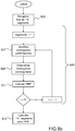
- the required RNP navigation performance is defined for flight portions. As illustrated on the figure 1 , the RNP varies according to whether the aircraft is on a portion of flight type 'Oceanic' or 'Enroute' or Terminal Area 'or' Approach '. Thus a procedure with some required performance refers to a specific block of space. The required level of performance translates into the width of a corridor according to the block of space. For example, a block of ocean space may have a corridor of width ranging from 4 to 10Nm where the symbol Nm corresponding to the marine mile and 1 nautical mile is equivalent to 1852 m.
- the required performance level translated into corridor width is generally 1 Nm at the beginning of the approach, down to 0.5 Nm for non-precision approaches , 0.3 Nm for precision approaches and up to 0.1 Nm for special approaches called 'RNP AR'.
- the variability of the required performance level allows to define a three-dimensional trajectory composed of Straight lines and curves, in a high traffic density environment, around areas sensitive to noise or across difficult terrain.
- the required performance level can be defined in a flight management system configuration file, manually by the pilot or called from a database present in the flight management system. It can also be defined by default depending on whether the space overflown by the aircraft is oceanic type, en route or airport, for example.
- a procedure with a certain required performance means that the navigation systems of the aircraft must be able to guarantee that the position of the aircraft is within a circle of radius xx Nm.
- the navigation system of the aircraft must be able to calculate the position of the aircraft in a circle of radius 5 Nm.
- the navigation system must ensure that the aircraft shall not leave a corridor of width 10 Nm (2 x RNP: accuracy limit) for 95% of the flight time, and ensure that the aircraft will never cross the border a corridor of width 20 Nm (4 x RNP: containment limit).
- the accuracy of the calculation of the position may vary along the flight.
- the Global Positioning System GPS satellite navigation devices have different levels of coverage depending on the geographical area considered. It is the same for the means of radio navigation.
- the inertial means they suffer from the problem of inertial drift inherent to these systems.
- TSE For the TSE, it is a first component (PDE) which in practice is considered negligible, a second component (FTE) which has 3 fixed values and which only applies to the active flight segment, the one that the aircraft is in progress, and a third component (NSE) that is related to sensor measurements.
- PDE first component
- FTE second component
- NSE third component
- This last component can vary along the trajectory because it depends on the performance of the sensors available around the position of the aircraft that is evolving.
- the error in the calculation of the position of the aircraft comes from the systems performing the calculation, in general the navigation system which is designated by the English terminology "Flight Management System” or FMS and which sets the road to follow at available to the staff on board and available to other on-board systems.
- This FMS system also allows a navigation aid, by displaying information useful to pilots, or by the communication of guidance instructions to an autopilot system.
- These systems provide an estimate of the so-called calculation error (EPE) for "Estimation Position Error", sometimes called (EPU) for "Estimation Position Uncertainty", two denominations that represent the same information.
- EPE calculation error
- EPU Estimatimation Position Error
- EPU Estimatimation Position Uncertainty
- the figure 4 illustrates, according to a known display, the estimated performance prediction under the variable UPE information according to the flight segments.
- the navigation system shall ensure that the position of the aircraft is within a circle of radius 'xx', this radius characterizing the UPR uncertainty in the calculation of the position.
- This circle depending on the speed of the aircraft takes the form of an ovoid to take into account the possible reduction of the required tolerance when passing from one flight segment to the next, at the exit of transition curve between two flight segments.
- the knowledge of the required navigation performance remains limited to the current flight segment, or even close to the end of the next segment, while the value of the required navigation performance is variable throughout the flight plan.
- the pilot does not benefit from the knowledge in advance of a change in the required navigation performance.
- the estimated navigation performance is a function of location sensors whose availability varies along the flight, and the calculation of the value of the estimated navigation performance is valid today only for the current flight segment followed by the aircraft.
- the knowledge of the estimated navigation performance remains limited to the current position of the aircraft and does not allow the pilot to anticipate the non-compliance with the required performance.
- FIGS. Figures 5a and 5b represent a page of a screen of a flight management system, a screen that is not accessible by the pilot in the "head-up" position and whose access requires the pilot to enter the flight menu. management system to display this page on a screen.
- the title "APPROACH” indicates that the information provided relates to an approach phase of an airport, for example.
- the word "REQUIRED” is displayed with a numerical value of 1.0 NM which indicates the level of performance required by the RNP procedure.
- the term "ESTIMATED” is displayed with a numeric value 0.60 NM which indicates the estimated level of performance.
- the requirement of the RNP procedure is satisfied, the estimated navigation performance level being lower than the required navigation performance level.
- the term “HIGH” associated with the term “ACCUR” represents a qualitative indication of the level of integrity of navigation calculations for the pilot and shows that the level of safety is considered high.
- the operator keeps the aircraft on a calculated trajectory which is called the "wire” trajectory as illustrated in FIG. figure 5b .
- the figure 5b represents a page of a navigation screen of the onboard flight management system on an aircraft which shows the trajectory to be followed by the aircraft, is generally easily accessible in the "head up" position by the pilot of the aircraft , requiring no maneuver to gain access.
- the current position of the aircraft is indicated by an aircraft-shaped symbol, represented in the center of three concentric circles of increasing radius.
- the trajectory of the aircraft is indicated by an axis or "wire” passing through the current position of the aircraft, a first and a second waypoint (CI27R, FI27R).
- the current position and the first point of passage define a first current portion of trajectory, a portion of trajectory being commonly called segment or "leg" in English.
- the first and second points of passage define a second portion of trajectory.
- Aircraft systems must meet and not exceed the required navigation performance expressed in the Nm width of a corridor.
- the operator has no information on the latitude of navigation in the corridor that is defined by the required navigation performance, and if an obstacle is in the corridor, the pilot will not see it. than at the last moment and the operation will require a request for emergency authorization to the ground operator.
- the navigation systems provide a required level of navigation performance and an estimated level of navigation performance that are limited to the current flight segment or at best the next segment for the current position of the aircraft.
- the known navigation systems do not allow the operator to know the "freedom" to navigate a defined corridor while respecting the RNP procedure.
- An object of the invention is to overcome the disadvantages of known systems.
- An object of the present invention is to provide a device and a method for calculating the estimated navigation performance prediction for a trajectory associated with a list of segments of a flight plan.
- Another object of the invention is to propose a device and a method for transforming a wire trajectory into a corridor trajectory, making it possible to guarantee compliance with the PBN navigation performance requirements as long as the aircraft does not leave the corridor trajectory .
- the device of the invention provides a piloting aid for an aircraft in the context of PBN procedures by offering an ability to predict the navigation performance estimate on a list of segments.
- the device of the invention provides in a simple way information trajectory corridor, allowing the operator of the aircraft to better control the trajectory of the aircraft and the expected and available performance, giving it easy access to the corridor in which performance is guaranteed and the limits not to be exceeded.
- the avoidance of an obstacle becomes an easy operation to be carried out by the pilot, without prior authorization request or with a very anticipated request because the operator or the pilot thanks to the knowledge of the estimated performance, respects the security that is displayed to him evidently by the corridor trajectory.
- the step of identifying the positioning systems consists of identifying all the satellite positioning systems, beacons and inertials available for each segment.
- the step of calculating the predicted navigation performance prediction is to determine whether a satellite prediction for each segment is accurate and available, and if so, to calculate the prediction of estimated navigation performance from the satellite data.
- the method compares the performance values of the beacon and inertial systems and calculates the estimated navigation performance prediction from the beacon positioning system data. or inertial with the lowest navigation performance calculation error for said segment.
- the calculation of the estimated navigation performance prediction, when it is made from the data of the inertial system takes into account the drift of the inertial system.
- the calculation of the predicted navigation performance prediction, when made from the beacon system data takes into account the performance of the beacons available in the geographic area of said segment.
- the navigation performance values of the satellite positioning systems come from a satellite receiver comprising a "RAIM" functionality on board the aircraft.
- a segment may be divided into sub-segments to perform the prediction calculation, the division may be made in fixed sub-segment lengths or considering the maximum range of the satellite predictions.
- the method may be executed for an estimated horizontal navigation performance prediction calculation and / or for an estimated vertical navigation performance prediction calculation.
- the method can be re-executed automatically if predictions of passage time or the flight plan change.
- the device comprises means capable of operating the steps of the method.
- the device is integrated into the flight management system (FMS) of the aircraft or alternatively as a component of an EFB-type embedded computer.
- FMS flight management system
- the invention also relates to a computer program product comprising code instructions for performing the steps of the method, when the program is run on a computer.
- the graphical representation is to superimpose on a wire path said predictions of estimated and required navigation performance.
- the method before the display step, makes it possible for each segment to subtract from the predictions of the required navigation performance, the predictions of estimated navigation performance, to construct a corridor trajectory, and the graphical representation consists in displaying said Predicted and required navigation performance predictions by corridor.
- the display step is to display a thread path for segments having an estimated browsing performance prediction greater than the required navigation performance prediction.
- the graphical representation consists of representing the contrasting navigation latitude on the corridor trajectory.
- the invention also covers a device for displaying predicted navigation performance predictions and required for a trajectory of an aircraft, the display device comprises a display means and calculation means making it possible to calculate performance predictions. estimated and required navigation, predictions of estimated navigation performance are calculated according to the steps of the claimed calculation method, and the device further comprises means for graphically representing on the display means predictions of estimated and required navigation performance.
- the display means may be a cockpit screen of the aircraft, such as a "Navigation Display” (ND) or a "Primary Flight Display” (PFD) screen.
- the figure 5 represents an exemplary display according to one embodiment of the invention, the estimated navigation performance prediction (EPU) for a wire path associated with a list of segments.
- This display allows the operator to monitor the navigation performance of the aircraft.
- a list of segments as defined in the description is a continuous sequence of segments (S1, S2, ..., Si, ..., Sn), the segments being straight or curved, each segment having a start point (PD Si ) and an end point (PF Si ) respectively defined by their latitude, longitude and altitude.
- any segment of a list is associated with a time or a passage time on the end point of the segment, and we speak of a list of dated segments.
- the segment S1 which has a starting point PD S1 and a final point PF S1 contains the representation of the aircraft in its current position
- the segment S2 which has a starting point PD S2 and a final point PF S2 displays a performance prediction of 0.1 Nm estimated EPU.
- the figure 6 represents an exemplary display according to one embodiment of the invention, the navigation performance prediction required for a wire path associated with a list of segments, where the list of segments (S1 to S5) is identical to that of the figure 5 .
- the required performance prediction is displayed in half-width of a corridor corresponding to the corridor within which the aircraft can circulate. This display allows the operator to anticipate a more demanding navigation performance requirement.
- this value is worth 1 Nm, meaning that the aircraft must travel in a corridor of width 2Nm on this flight portion, and for the segment S5, this value is 0.3 Nm, meaning that the aircraft must circulate in a corridor of width 0.6 Nm on this portion of flight.
- the Figures 7 and 8 are display examples combining predictions of required and estimated navigation performance for a wire path associated with a list of segments, according to different embodiments of the invention.
- the display of the figure 7 may be a representation consistent with the mental representation of an operator with a first UPR corridor and a second corridor corresponding to the required navigation performance.
- the display of the figure 8 allows the operator even in unmanaged mode (where the NAV mode of automatic tracking of the trajectory is not engaged) to know the relative situation of the aircraft compared to the regulatory limit (the width of the "required" corridor).
- the figure 9a illustrates, according to an embodiment of the invention, steps of the method for calculating the estimated performance predictions for a list of segments of a flight plan.
- the device of the invention can be implemented at an embedded computer separated from the FMS, type "Electronic Flight Bag” (EFB) according to the conspicuous anglicism.
- EFB Electronic Flight Bag
- the EFB is an electronic information management device that helps crews perform flight management tasks. It is an IT platform that can host software applications specifically developed to perform functions such as take-off, centering performance calculations.
- the method then makes it possible (904) to retrieve the performance values of a set of positioning systems from the aircraft.
- the main known positioning systems are radio navigation beacons on the ground (eg VOR, TACAN, DME, LOC, MLS %), inertial navigation systems (eg: IRS, ADIRS, AHRS, etc %) and satellite based positioning systems (eg GNSS, GPS, GLONASS ). Each type of positioning system is associated with a navigation performance.
- the method makes it possible to calculate for each segment 'i' of the list, an estimated navigation performance prediction, taking into account the position of the segment 'i' considered and the prediction of time. in this segment, as well as data from positioning systems through inertial units, navigation beacons and satellite systems.
- the calculation of the estimated performance prediction (908) is based on an innovative use of the functions of the satellite reception systems on board the aircraft, and information produced by the different position sensors.
- the method of the invention makes it possible to compare the information produced by the different positioning systems and to select, for the calculation of the estimated performance prediction, the one that offers the best navigation performance for each segment 'i', depending the position of the segment and the predicted time of passage.
- the output (910) of the calculation method for predicting the estimated navigation performance is the list of 'N' segments for the entire flight plan associated with the trajectory, with for each segment, the predicted estimated navigation performance (EPU_PREDIT) calculated.
- the method for calculating the estimated navigation performance prediction over the entire flight plan is carried out at regular intervals, if no automatic recovery event has appeared for a certain duration (15mn for example), to account for satellite failures, navigational flag failures, or other events.
- the method for calculating the estimated navigation performance prediction can be restarted automatically if the predictions of passage time on the segments change significantly, for example due to a change of speed, weather phenomena ( high winds).
- the calculation of the estimated performance prediction can be restarted following a restart of the computation of the required performance prediction.
- the figure 9b illustrates according to an embodiment of the invention, steps of the method for calculating the performance predictions required for a list of segments of a flight plan.
- the method begins with a step (903) of receiving a list of 'N' flight segments for a trajectory associated with a flight plan.
- a next step (905) the method makes it possible to calculate for each segment of the list, a prediction of required performance.
- the method makes it possible (907) to identify, via the information of the navigation database and the operator inputs, the set of navigation performance constraints required, to select (909) the most restrictive contingency, and to calculate (911) a prediction of required performance for the segment under consideration.
- the system only considers the corridor defined by the operator if it is lower than that of the regulation.
- the corridor When the corridor is defined for a segment in the database, it corresponds to the required performance regulation for that segment and is applicable unless the pilot value is more stringent.
- a default corridor value determined according to the geographical area of flight (terminal, en-route, approach), is applied for that segment. segment.
- the corridor is defined for a segment with the default value, it corresponds to the performance regulation required for this segment and it is applicable unless the pilot value is more restrictive.
- the figure 14 illustrates which corridor value (Default, Driver, Database) is taken into account for a segment 'i'.
- the output (913) of the computation method for predicting the required navigation performance is the list of 'N' segments for the entire flight plan associated with the trajectory, with for each segment the required navigation performance prediction (RPN). ) calculated.
- the purpose of the calculation system for the prediction of the required navigation performance is to define for each segment of the list, the required navigation performance that is applicable, ie which is in compliance with the regulations. .
- the calculation of the required navigation performance prediction is not restarted regularly or automatically.
- the calculation is restarted following a modification by the operator of the list of segments (by addition, deletion of segments) or following a modification by the operator of the value of the corridor associated with a segment.
- the method implemented by the device of the invention makes it possible to combine the predicted (9010) and required (9020) estimated navigation performance predictions for a list of segments (9000), in order to construct (9030) a corridor trajectory navigation.
- two approaches are proposed for constructing a corridor from the two types of performance prediction.
- the This method allows the predicted performance to be subtracted from that required, so that it can never exceed the required contingency, regardless of the position of the aircraft in that corridor.
- the advantage of this solution is that if a degradation of the navigation performance occurs, it is progressive and visible by the operator. The resulting display of this approach is illustrated on the figure 18 .
- An alternative approach to constructing a corridor is to consider a "1 x corridor" width corridor when the predicted performance is strictly inferior to the required performance. If the predicted performance is greater than or equal to the required performance, the ribbon becomes a wire. In this case the guarantee is not to stay inside the corridor but to guarantee never to cross the corridor twice as wide, which is the main safety objective.
- the advantage of this solution is that the corridor in which the aircraft can fly is wider. The resulting display of this approach is illustrated on the figure 19 .
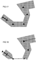
- the corridor can be displayed (9040) on demand on a screen for the pilot in the form of a "ribbon" trajectory according to different variants illustrated by the Figures 15 to 20 .
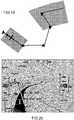
- the display device may be a conventional cockpit screen such as a “Navigation Display” (ND) or a “Primary Flight Display” (PFD) screen with a “Synthetic Visual System” (SVS) capability as shown in FIG. figure 20 .
- ND Navigation Display
- PFD Primary Flight Display
- SVS Synthetic Visual System
- the "ribbon" trajectory is constructed so as never to leave the contingency (width of the corridor) in relation to the reference trajectory corresponding to the list of initial segments of the flight plan, illustrated on the Figures 15 and 16 .
- the only representation of the points of the segments without drawing the thread that joins them is another example of representation proposed on the corridor. figure 17 .
- an alert message may be sent to the operator when this segment will soon become the active segment, that is, when this segment is near the beginning of the segment list.
- all displays may be temporarily disabled automatically or manually.
- the figure 11 illustrates the step of calculating the predicted navigation performance prediction EPU for a segment 'i' of the list (step 908 of the figure 9a ).
- the method uses satellite-based satellite reception systems functionalities onboard the aircraft for monitoring satellites and detecting failed satellites.
- the method uses a capacity of these systems to predict the availability of satellites for a given date and location, known as "RAIM” functionality for "Reliability, Availability, and Integrity Monitoring”.
- RAIM Reliability, Availability, and Integrity Monitoring.
- Receivers equipped with RAIM technology are able to predict the integrity of the GPS positioning signals received from the satellites and able to detect by a function called "FDE” for "Fault Detection and Exclusion” the failed satellites and exclude them from the calculation the position of the aircraft.
- the prediction of estimated navigation performance is related to the number and position of available satellites at a given time or time.
- the process is iterative and operates segment after segment (1102, 1124).
- the method determines (1104) whether the satellite prediction is accurate and available using the RAIM functionality. In the positive case, for any segment where the satellite prediction is accurate and available, the method makes it possible to establish the prediction of estimated navigation performance as a function of the value of the predicted satellite performance, named "EPU_SATELLITE" (1110).
- the method makes it possible to combine the satellite information (1104) with the information (1106) of the systems based on inertial units (IRS, AHRS, etc.), for example to cover the cases where the satellite system gives an aberrant aircraft position value (due for example to a transient loss of satellites).
- the inertial system will then passivate this response. Indeed, the inertial system drifts slowly and the aircraft position of the satellite system which is accurate in the long term will passivate this drift by allowing the inertial system to be recalibrated.
- the satellite system provides the value of its performance (1104) and the use of the inertial system (1106) the method consolidates this value and calculate a prediction of estimated navigation performance called "EPU_HYBRID" (1108).
- the method makes it possible to take counts the performance information provided by other positioning systems - beacons and inertials.
- the method makes it possible to calculate (1112) the estimated navigation performance named EPU_BALISES associated with the types of beacons available around the segment 'i' that do not have satellite information (without RAIM), and makes it possible to calculate (1114) the performance of estimated navigation, named EPU_INERTIE, associated with the inertial systems, taking into account the inertial drift on the segment 'i' «without RAIM».
- the method makes it possible to compare (1116) the EPU_BALISES and EPU_INERTIE values and to take the value (1118, 1120) corresponding to the best performance.
- the method calculates the EPU_BALISES value (1112) only on a non availability of the capacity RAIM. To do this, the system searches if in the geographical area of the segment 'i'"withoutRAIM", radio navigation tags exist (VOR, TACAN, DME, LOC, ILS, MLS ). If so, the method calculates the estimated performance associated with the tags based on the available tags. For example, the EPU_BALISES is of the order of 4Nm for VOR tags whereas it can be of the order of 0.3Nm for DME beacons.
- the EPU_BALISES for segment 'i' is compared (1116) with EPU_INERTIE of the same segment 'i' whose calculation is described hereafter. Similarly, the method calculates the value of EPU_INERTIE (1114) only on a non-availability of the capacity RAIM.
- the inertial systems (IRS, AHRS) have a value of EPU_INERTIE variable with time because of their intrinsic drift which is of the order of 2Nm to 4Nm per hour according to the performance of the systems and in the absence of registration by the satellite position.
- the method initializes (1204) the EPU_lNERTlE_i of this segment with the last value of the EPU_SATELLlTE.
- the EPU_INERTIE of the segment "i" corresponding is the EPU_INERTIE of the segment i-1 'increased of the drift of the system inertial which is proportional to the travel time of segment 'i'.
- An estimate of the drift can be made linearly along the segment. Such an operation can be continued iteratively as long as the EPU_INERTIE value of the segment remains lower than that of the EPU_BALISES.
- the method calculates (1122) an EPU value of the segment "predicted EPU", and iterates on the following segment 'N + 1' (1124) so as to generate a list of 'N' segments with an estimated estimated navigation performance prediction calculated for each segment (910).
- the UPR has a value dependent on the available positioning systems.
- the satellite system makes it possible to reach EPU_SATELLITE (1110) of the order of 0.1 Nm.
- the method makes it possible to determine whether the length of a segment of the list is too long, compared with the configuration of the satellites or the presence of ground beacons.
- the method makes it possible to split the segment into several segments. sub-segments of fixed length so as to obtain an adequate predicted performance value.
- a maximum segment length can be set, such as 100Nm for example.
- another method for cutting a segment that is too long is to use the RAIM response that in the current systems gives the RAIM state for -15mn, -5mn, 0mn, + 5mn and + 15mn compared to the segment position.
- the figure 13 illustrates the type of UPE considered for multiple segments based on the availability or not of the RAIM functionality.
- the prediction provided is based on the EPU_SATELLITE.
- the prediction provided is based on the EPU_INERTIE as long as it is lower than the UU_BALISES and becomes based on the EPU_BALISES after the next end point where it becomes superior to it.
- the method for calculating the vertical performance prediction takes into account the different vertical positioning systems with their associated precision.
- the main known systems are the satellite positioning systems (eg GPS, GLONASS, etc.), the systems based on barometric pressure or radio (Air Data Computer ADC, Radio Altimeter RA) and the navigation systems based on inertia (eg IRS, ADIRS, AHRS, etc ).
- GPS Global System for Mobile Communications
- GLONASS Global System for Mobile Communications
- barometric pressure or radio Air Data Computer ADC, Radio Altimeter RA
- inertia eg IRS, ADIRS, AHRS, etc.
- the method for calculating the predicted and estimated performance predictions enables a vertical navigation corridor to be constructed which can be displayed on demand on a screen for the pilot.
- the vertical "ribbon" profile is constructed in such a way as to never leave the "2 x width of the corridor" contingency (twice the deviation tolerance) vertical compared to the vertical reference profile corresponding to the segment list.
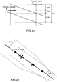
- the figures 22 and 23 illustrate vertical corridor display variants on a "Vertical Display” (VD) or a “Primary Flight Display” (PFD) with a “Synthetic Visual System 3D” (SVS 3D).
- VD Very Display
- PFD Primary Flight Display
- SVS 3D Synthetic Visual System 3D
- the system can display the vertical ribbon profile for the predictions required and estimated based on dashed lines as shown in the figure. figure 21 .
- Another proposal to display this ribbon path by the display system is provided by the figure 22 .
- the method of calculating the estimated and required predictions on a list of segments is carried by a specific partition of a hardware platform specific to the avionics but different from that of the FMS.
- this calculation is performed on the FMS execution platform by components suitable for calculations.
- the advent of modular avionics integrated on recent aircraft has allowed the definition of execution platforms and digital communication between functions.
- this evolution has led to an increase in complexity - including the internal complexity of the functions but also the complexity of the avionics system configuration process - and the need for increased performance and resource optimization.
- the new hardware platforms are equipped with management capabilities (operations, security and maintenance), energy optimization and localization, which go beyond the standard functions of known platforms.
- the invention relates to a computer program product comprising code instructions for carrying out the steps of the method according to the invention.
- the method can be implemented from hardware and / or software elements.
- the method may be available as a computer program product on a computer readable medium.
- the method can be implemented on a system that can use one or several dedicated electronic circuits or a general purpose circuit.
- the technique of the method according to the invention can be realized on a reprogrammable calculation machine (a processor or a microcontroller for example) executing a program comprising a sequence of instructions, or on a dedicated computing machine (for example a set of doors as an FPGA or an ASIC, or any other hardware module).
- the different modules of the system according to the invention can be implemented on the same processor or on the same circuit, or distributed over several processors or several circuits.
- the modules of the system according to the invention consist of calculation means including a processor.
- the reference to a computer program that, when executed, performs any of the functions described above, is not limited to an application program running on a single host computer.
- the terms computer program and software are used herein in a general sense to refer to any type of computer code (for example, application software, firmware, microcode, or any other form of computer code). computer instruction) that can be used to program one or more processors to implement aspects of the techniques described herein.
Landscapes
- Engineering & Computer Science (AREA)
- Radar, Positioning & Navigation (AREA)
- Remote Sensing (AREA)
- Physics & Mathematics (AREA)
- General Physics & Mathematics (AREA)
- Aviation & Aerospace Engineering (AREA)
- Automation & Control Theory (AREA)
- Computer Networks & Wireless Communication (AREA)
- Traffic Control Systems (AREA)
- Navigation (AREA)
- Position Fixing By Use Of Radio Waves (AREA)
Claims (22)
- Verfahren zum Berechnen einer Vorhersage von geschätzter Navigationsleistung für eine Flugbahn eines Luftfahrzeugs, wobei das Verfahren von einer Rechenplattform für Luftfahrzeuge ausgeführt wird und die folgenden Schritte beinhaltet:- Empfangen (902) einer Liste von Segmenten, die alle Segmente eines Flugplans mit einer Vorhersage einer mit jedem Segment assoziierten Durchflugzeit umfasst;- für jedes Segment der Liste:- Identifizieren (904) der in der geografischen Zone des Segments verfügbaren Positionierungssysteme;- Bestimmen (906) der identifizierten Leistungswerte der Positionierungssysteme und Auswählen des Positionierungssystems mit dem geringsten Navigationsleistungsrechenfehler für die Position des Segments und die vorhergesagte Durchflugzeit;- Berechnen (908) einer Vorhersage von geschätzter Navigationsleistung auf der Basis von Daten von dem gewählten Positionierungssystem; und- Aktualisieren (912) der Liste von Segmenten mit der mit jedem Segment assoziierten Vorhersage von geschätzter Navigationsleistung.
- Verfahren nach Anspruch 1, bei dem der Schritt des Identifizierens der Positionierungssysteme im Identifizieren aller Satellitenpositionierungssysteme, Baken und Trägheitseinheiten besteht, die für das Segment zur Verfügung stehen.
- Verfahren nach Anspruch 1 oder 2, bei dem der Schritt des Berechnens der Vorhersage von geschätzter Navigationsleistung im Feststellen besteht, ob eine Satellitenvorhersage für das Segment präzise und verfügbar ist, und wenn ja, Berechnen der Vorhersage von geschätzter Navigationsleistung auf der Basis der Satellitendaten.
- Verfahren nach Anspruch 3, das, wenn die Satellitenvorhersage für das Segment nicht präzise oder nicht verfügbar ist, einen Schritt des Vergleichens der Leistungswerte von Baken- und Trägheitssystemen und das Berechnen der Vorhersage von geschätzter Navigationsleistung auf der Basis der Daten des Baken- oder Trägheitspositionierungssystems mit dem geringsten Navigationsleistungsrechenfehler für das Segment beinhaltet.
- Verfahren nach Anspruch 4, bei dem die Berechnung der Vorhersage von geschätzter Navigationsleistung, wenn sie auf der Basis der Daten des Trägheitssystems erfolgt, die Drift des Trägheitssystems berücksichtigt.
- Verfahren nach Anspruch 4, bei dem die Berechnung der Vorhersage von geschätzter Navigationsleistung, wenn sie auf der Basis von Daten des Bakensystems erfolgt, die Leistung der in der geografischen Zone des Segments verfügbaren Baken berücksichtigt.
- Verfahren nach einem der Ansprüche 1 bis 6, bei dem die Navigationsleistungswerte der Satellitenpositionierungssysteme von einem Satellitenempfänger kommen, der eine an Bord des Luftfahrzeugs installierte "RAIM"-Funktionalität umfasst.
- Verfahren nach einem der Ansprüche 1 bis 7, das ferner einen Schritt des Unterteilens des Segments in Untersegmente beinhaltet, um die Vorhersageberechnung zu bewirken, wobei das Beschneiden gemäß den Längen von festen Sub segmenten oder unter Berücksichtigung des maximalen Bereichs der Satellitenvorhersagen erfolgen kann.
- Verfahren nach einem der Ansprüche 1 bis 8, bei dem die Schritte für eine Berechnung der Vorhersage von geschätzter horizontale Navigationsleistung und/oder für eine Berechnung der Vorhersage von geschätzter vertikaler Navigationsleistung ausgeführt werden.
- Verfahren nach einem der Ansprüche 1 bis 9, bei dem die Schritte automatisch erneut ausgeführt werden, wenn sich Durchflugzeitvorhersagen oder der Flugplan ändern.
- Vorrichtung zum Berechnen der Vorhersage von geschätzter Navigationsleistung für eine Flugbahn eines Luftfahrzeugs, wobei die Vorrichtung Folgendes umfasst:- Mittel, die den Empfang einer Segmentliste zulassen, die alle Segmente eines Flugplans umfasst, mit einer Vorhersage einer mit jedem Segment assoziierten Durchflugzeit;- Mittel, die für jedes Segment der Liste Folgendes zulassen:- Identifizieren der in der geografischen Zone des Segments verfügbaren Positionierungssysteme;- Bestimmen der Leistungswerte der identifizierten Positionierungssysteme und Auswählen des Positionierungssystems mit dem kleinsten Navigationsleistungsrechenfehler für die Position des Segments und der vorhergesagten Durchflugzeit;- Berechnen einer Vorhersage von geschätzter Navigationsleistung auf der Basis von Daten von dem gewählten Positionierungssystem; und- Mittel, die die Aktualisierung der Segmentliste mit der mit jedem Segment assoziierten Vorhersage von geschätzter Navigationsleistung erlauben.
- Vorrichtung nach Anspruch 11, bei der die Mittel zum Implementieren der Schritte des Verfahrens nach einem der Ansprüche 2 bis 10 ausgelegt sind.
- Flugmanagementsystem (FMS) oder EFB-Bordcomputer, umfassend eine Vorrichtung zum Berechnen einer Vorhersage von geschätzter Navigationsleistung für eine Flugbahn eines Luftfahrzeugs nach Anspruch 11 oder 12.
- Computerprogrammprodukt, wobei das Computerprogramm Code-Befehle umfasst, die das Ausführen der Schritte des Verfahrens nach einem der Ansprüche 1 bis 10 zulassen, wenn das Programm auf einem Computer ausgeführt wird.
- Verfahren zum Anzeigen von Vorhersagen von geschätzter Navigationsleistung, die für eine Flugbahn eines Luftfahrzeugs erforderlich sind, wobei das Verfahren von einer Rechenplattform für Luftfahrzeuge ausgeführt wird und die folgenden Schritte beinhaltet:- Berechnen (9010) von Vorhersagen von geschätzter Navigationsleistung für eine Liste von Segmenten eines Flugplans gemäß den Schritten des Verfahrens nach einem der Ansprüche 1 bis 10;- Berechnen (9020), für dieselbe Segmentliste, von Vorhersagen einer benötigten Navigationsleistung; und- Darstellen (9040) der Vorhersagen von geschätzter und benötigter Navigationsleistung auf einem Anzeigemittel.
- Verfahren nach Anspruch 15, bei dem der Schritt des Berechnens von Vorhersagen von benötigter Navigationsleistung die folgenden Schritte beinhaltet:- Empfangen der Liste von Segmenten des Flugplans;- für jedes Segment der Liste:- Identifizieren aller Eventualitäten, die Navigationsleistungsbeschränkungen bilden;- Bestimmen und Auswählen der am meisten beschränkenden Eventualität für das Segment;- Berechnen einer Vorhersage der benötigten Navigationsleistung in Abhängigkeit von Daten der gewählten Eventualität; und- Aktualisieren der Liste von Segmenten mit der Vorhersage von mit jedem Segment assoziierter benötigter Navigationsleistung.
- Verfahren nach Anspruch 15 oder 16, bei dem die grafische Darstellung im überlagerten Anzeigen der Vorhersagen von geschätzter und benötigter Navigationsleistung auf einer Drahtflugbahn besteht.
- Verfahren nach einem der Ansprüche 15 bis 17, das vor dem Anzeigeschritt einen Schritt beinhaltet, der für jedes Segment darin besteht, von den Vorhersagen der benötigten Navigationsleistung die Vorhersagen der geschätzten Navigationsleistung zu subtrahieren, um eine Korridorflugbahn zu konstruieren, und wobei die grafische Darstellung darin besteht, die Vorhersagen der geschätzten und benötigten Navigationsleistung in Abhängigkeit von dem Korridor anzuzeigen.
- Verfahren nach Anspruch 18, bei dem der Anzeigeschritt darin besteht, eine Flugbahn für die Segmente mit einer Vorhersage der geschätzten Navigationsleistung anzuzeigen, die größer ist als die Vorhersage der benötigten Navigationsleistung.
- Verfahren nach Anspruch 18 oder 19, bei dem die grafische Darstellung darin besteht, die Breite der Navigation im Kontrast zur Korridorbahn darzustellen.
- Vorrichtung zum Anzeigen von Vorhersagen von geschätzter und benötigter Navigationsleistung für eine Flugbahn eines Luftfahrzeugs, wobei die Anzeigevorrichtung ein Anzeigemittel und Rechenmittel umfasst, die das Berechnen der Vorhersagen von geschätzter und benötigter Navigationsleistung zulassen, wobei die Vorhersagen von geschätzter Navigationsleistung gemäß den Schritten des Verfahrens nach einem der Ansprüche 1 bis 10 berechnet werden, wobei die Vorrichtung ferner Mittel zum grafischen Darstellen der Vorhersagen von geschätzter und benötigter Navigationsleistung auf dem Anzeigemittel umfassen.
- Anzeigevorrichtung nach Anspruch 21, bei der das Anzeigemittel ein Bildschirm im Cockpit des Luftfahrzeugs wie ein "Navigation Display" (ND) oder ein "Primary Flight Display" (PFD) Bildschirm ist.
Applications Claiming Priority (1)
| Application Number | Priority Date | Filing Date | Title |
|---|---|---|---|
| FR1601058A FR3053779B1 (fr) | 2016-07-07 | 2016-07-07 | Dispositif et methode de calcul de prediction de performance de navigation estimee |
Publications (2)
| Publication Number | Publication Date |
|---|---|
| EP3267156A1 EP3267156A1 (de) | 2018-01-10 |
| EP3267156B1 true EP3267156B1 (de) | 2019-08-21 |
Family
ID=56943579
Family Applications (1)
| Application Number | Title | Priority Date | Filing Date |
|---|---|---|---|
| EP17179564.4A Active EP3267156B1 (de) | 2016-07-07 | 2017-07-04 | Vorrichtung und methode zur berechnung der vorhersage einer geschätzten navigationsleistung |
Country Status (4)
| Country | Link |
|---|---|
| US (1) | US9983009B2 (de) |
| EP (1) | EP3267156B1 (de) |
| CN (1) | CN107591033B (de) |
| FR (1) | FR3053779B1 (de) |
Families Citing this family (13)
| Publication number | Priority date | Publication date | Assignee | Title |
|---|---|---|---|---|
| DE102017222356A1 (de) * | 2017-12-11 | 2019-06-13 | Robert Bosch Gmbh | Verfahren zum Betreiben eines GNSS-Sensors eines Fahrzeugs |
| US11302204B2 (en) * | 2018-04-02 | 2022-04-12 | Ge Aviation Systems Llc | Flight management system and method of updating |
| US11598880B2 (en) * | 2018-10-04 | 2023-03-07 | The Boeing Company | Detecting fault states of an aircraft |
| FR3088443B1 (fr) * | 2018-11-13 | 2022-03-11 | Thales Sa | procédé et système de navigation d'aéronef |
| FR3094083B1 (fr) | 2019-03-21 | 2021-08-13 | Thales Sa | Determination d'une trajectoire raccourcie d'un mobile evoluant dans un corridor |
| FR3112883B1 (fr) * | 2020-07-22 | 2023-06-09 | Thales Sa | Dispositif et procede d’aide au guidage d’aeronef |
| FR3118261A1 (fr) * | 2020-12-23 | 2022-06-24 | Thales | Procédé et dispositif d’aide au guidage d’aéronefs |
| CN113063443B (zh) * | 2021-03-19 | 2023-12-01 | 四川大学 | 基于实际导航性能的飞行误差实时评估方法 |
| FR3121983B1 (fr) * | 2021-04-14 | 2023-04-14 | Thales Sa | Adaptation automatique du profil vertical d’un aéronef en fonction d’une incertitude de position |
| FR3128284B1 (fr) * | 2021-10-18 | 2024-04-05 | Dassault Aviat | Système de calcul de mission d'un aéronef indiquant un risque de perte d'optimalité de la trajectoire réellement suivie par l'aéronef et procédé associé |
| CN114047782B (zh) * | 2021-11-16 | 2024-09-13 | 中国商用飞机有限责任公司 | 飞行辅助方法、装置、电子设备和可读存储介质 |
| CN114781063B (zh) * | 2022-04-27 | 2024-07-09 | 中国民航大学 | 基于fte估计的导航性能分配及监视方法 |
| EP4418236A1 (de) * | 2023-02-16 | 2024-08-21 | Rockwell Collins, Inc. | Visuelle anzeige eines uam-korridors |
Citations (1)
| Publication number | Priority date | Publication date | Assignee | Title |
|---|---|---|---|---|
| FR3008818A1 (fr) * | 2013-07-22 | 2015-01-23 | Airbus Operations Sas | Dispositif et procede de prediction au sol de la precision, l'integrite et la disponibilite de la position d'un aeronef le long d'une trajectoire. |
Family Cites Families (10)
| Publication number | Priority date | Publication date | Assignee | Title |
|---|---|---|---|---|
| US7366591B2 (en) * | 2004-06-21 | 2008-04-29 | Honeywell International, Inc. | System and method for vertical flight planning |
| US8164485B2 (en) * | 2006-04-13 | 2012-04-24 | The United States Of America As Represented By The Administrator Of The National Aeronautics And Space Administration | System and method for aiding pilot preview, rehearsal, review, and real-time visual acquisition of flight mission progress |
| CN101739845B (zh) * | 2009-12-18 | 2012-11-14 | 中国航空无线电电子研究所 | 基于航空数据链信息的民机航空电子验证系统及其方法 |
| US9020681B2 (en) * | 2010-06-08 | 2015-04-28 | Honeywell International Inc. | Display of navigation limits on an onboard display element of a vehicle |
| FR2998065B1 (fr) * | 2012-11-09 | 2016-12-09 | Thales Sa | Systeme permettant d'anticiper les precisions de navigation requises |
| US9061770B2 (en) * | 2013-01-28 | 2015-06-23 | Honeywell International Inc. | Electronic flight bag systems and methods for verifying correct takeoff performance data entry |
| EP2889579B1 (de) * | 2013-12-31 | 2018-02-14 | The Boeing Company | System und Verfahren zum Definieren und Vorhersagen von Flugzeugflugbahnen |
| FR3017967B1 (fr) * | 2014-02-21 | 2016-03-04 | Thales Sa | Procede et systeme de gestion de vol |
| FR3028975B1 (fr) * | 2014-11-26 | 2016-12-02 | Thales Sa | Procede de detection d'erreur d'un systeme de gestion de vol et de guidage d'un aeronef et syteme de gestion de vol et de guidage a haute integrite |
| US9464901B1 (en) * | 2015-05-28 | 2016-10-11 | Rockwell Collins, Inc. | RNP-scaled waypoint symbology generating system, device, and method |
-
2016
- 2016-07-07 FR FR1601058A patent/FR3053779B1/fr not_active Expired - Fee Related
-
2017
- 2017-07-04 EP EP17179564.4A patent/EP3267156B1/de active Active
- 2017-07-05 US US15/642,238 patent/US9983009B2/en active Active
- 2017-07-07 CN CN201710552468.5A patent/CN107591033B/zh active Active
Patent Citations (1)
| Publication number | Priority date | Publication date | Assignee | Title |
|---|---|---|---|---|
| FR3008818A1 (fr) * | 2013-07-22 | 2015-01-23 | Airbus Operations Sas | Dispositif et procede de prediction au sol de la precision, l'integrite et la disponibilite de la position d'un aeronef le long d'une trajectoire. |
Also Published As
| Publication number | Publication date |
|---|---|
| CN107591033B (zh) | 2022-03-11 |
| FR3053779B1 (fr) | 2018-06-29 |
| FR3053779A1 (fr) | 2018-01-12 |
| CN107591033A (zh) | 2018-01-16 |
| EP3267156A1 (de) | 2018-01-10 |
| US9983009B2 (en) | 2018-05-29 |
| US20180010916A1 (en) | 2018-01-11 |
Similar Documents
| Publication | Publication Date | Title |
|---|---|---|
| EP3267156B1 (de) | Vorrichtung und methode zur berechnung der vorhersage einer geschätzten navigationsleistung | |
| US9310222B1 (en) | Flight assistant with automatic configuration and landing site selection method and apparatus | |
| FR3053780A1 (fr) | Dispositif et methode de calcul de prediction de performance de navigation requise | |
| EP1902276B1 (de) | Einrichtung zum unterstützen eines vertikalführungsanflugs für ein flugzeug | |
| EP2573586B1 (de) | Verfahren und System zur Steuerung eines Luftfahrzeugs in der Anflugphase auf eine Landebahn | |
| FR2906921A1 (fr) | Procede de formation d'une trajectoire d'urgence en 3d pour aeronef et dispositif de mise en oeuvre | |
| FR2898972A1 (fr) | Procede et dispositif de surveillance de l'altitude de vol minimum d'un aeronef | |
| CA2457278C (fr) | Procede et dispositif d'aide au pilotage d'un aeronef lors d'une approche de non precision pendant une phase d'atterrissage | |
| FR3021107A1 (fr) | Procede d'aide a la navigation d'un aeronef avec correlation d'informations dynamiques avec une trajectoire de vol 4d | |
| FR2940426A1 (fr) | Dispositif d'assistance au choix d'un aeroport de deroutement | |
| EP3244977B1 (de) | Verfahren und system zur anzeige von informationen in bezug auf ein flugzeug, vorrichtung zur erzeugung der besagten informationen und zugehöriges computerprogrammprodukt | |
| EP3346282B1 (de) | Elektronische vorrichtung zur überwachung mindestens eines satellitennavigationssignals in der annäherungsphase an eine landebahn, entsprechendes überwachungsverfahren und entsprechendes computerprogramm | |
| FR3038750A1 (fr) | Procede d'integration d'un nouveau service de navigation dans un systeme avionique embarque a architecture ouverte de type client-serveur, en particulier d'un service de manoeuvre fim | |
| FR3026214A1 (fr) | Procede de gestion d'alertes | |
| FR2904706A1 (fr) | Procede et dispositif pour determiner une hauteur de decision lors d'une approche autonome d'un aeronef. | |
| FR3030794A1 (fr) | Procede et systeme de guidage d'un aeronef | |
| FR3008818A1 (fr) | Dispositif et procede de prediction au sol de la precision, l'integrite et la disponibilite de la position d'un aeronef le long d'une trajectoire. | |
| FR3043487A1 (fr) | Gestion de trajectoire d'un aeronef en cas de panne moteur | |
| FR3007545A1 (fr) | Procede systeme et programme d ordinateur pour fournir sur une interface homme machine les donnees relatives a un aspect du fonctionnement d un aeronef | |
| FR2906622A1 (fr) | Susteme de gestion du vol tolerant aux sautes de distances. | |
| EP1465136B1 (de) | Verfahren und Vorrichtung zur Bord-Pilotenunterstützung bei Abwesenheit der Flugsicherung | |
| EP2369297B1 (de) | Vorrichtung zur Flughilfe für Luftfahrzeug | |
| FR2998065A1 (fr) | Systeme permettant d'anticiper les precisions de navigation requises | |
| EP1459979A1 (de) | Verfahren und Vorrichtung zur Bestimmung von mindestens einer Angabe bezüglich der vertikalen Position eines Luftfahrzeuges | |
| FR3112883A1 (fr) | Dispositif et procede d’aide au guidage d’aeronef |
Legal Events
| Date | Code | Title | Description |
|---|---|---|---|
| PUAI | Public reference made under article 153(3) epc to a published international application that has entered the european phase |
Free format text: ORIGINAL CODE: 0009012 |
|
| STAA | Information on the status of an ep patent application or granted ep patent |
Free format text: STATUS: THE APPLICATION HAS BEEN PUBLISHED |
|
| AK | Designated contracting states |
Kind code of ref document: A1 Designated state(s): AL AT BE BG CH CY CZ DE DK EE ES FI FR GB GR HR HU IE IS IT LI LT LU LV MC MK MT NL NO PL PT RO RS SE SI SK SM TR |
|
| AX | Request for extension of the european patent |
Extension state: BA ME |
|
| STAA | Information on the status of an ep patent application or granted ep patent |
Free format text: STATUS: REQUEST FOR EXAMINATION WAS MADE |
|
| 17P | Request for examination filed |
Effective date: 20180626 |
|
| RBV | Designated contracting states (corrected) |
Designated state(s): AL AT BE BG CH CY CZ DE DK EE ES FI FR GB GR HR HU IE IS IT LI LT LU LV MC MK MT NL NO PL PT RO RS SE SI SK SM TR |
|
| STAA | Information on the status of an ep patent application or granted ep patent |
Free format text: STATUS: EXAMINATION IS IN PROGRESS |
|
| 17Q | First examination report despatched |
Effective date: 20180830 |
|
| RIC1 | Information provided on ipc code assigned before grant |
Ipc: G01C 23/00 20060101AFI20181206BHEP Ipc: G08G 5/00 20060101ALI20181206BHEP |
|
| REG | Reference to a national code |
Ref country code: DE Ref legal event code: R079 Ref document number: 602017006280 Country of ref document: DE Free format text: PREVIOUS MAIN CLASS: G01C0023000000 Ipc: G01C0021200000 |
|
| RIC1 | Information provided on ipc code assigned before grant |
Ipc: G08G 5/00 20060101ALI20190123BHEP Ipc: G01C 21/20 20060101AFI20190123BHEP Ipc: G01C 23/00 20060101ALI20190123BHEP |
|
| GRAP | Despatch of communication of intention to grant a patent |
Free format text: ORIGINAL CODE: EPIDOSNIGR1 |
|
| STAA | Information on the status of an ep patent application or granted ep patent |
Free format text: STATUS: GRANT OF PATENT IS INTENDED |
|
| INTG | Intention to grant announced |
Effective date: 20190304 |
|
| GRAS | Grant fee paid |
Free format text: ORIGINAL CODE: EPIDOSNIGR3 |
|
| GRAA | (expected) grant |
Free format text: ORIGINAL CODE: 0009210 |
|
| STAA | Information on the status of an ep patent application or granted ep patent |
Free format text: STATUS: THE PATENT HAS BEEN GRANTED |
|
| AK | Designated contracting states |
Kind code of ref document: B1 Designated state(s): AL AT BE BG CH CY CZ DE DK EE ES FI FR GB GR HR HU IE IS IT LI LT LU LV MC MK MT NL NO PL PT RO RS SE SI SK SM TR |
|
| REG | Reference to a national code |
Ref country code: GB Ref legal event code: FG4D Free format text: NOT ENGLISH |
|
| REG | Reference to a national code |
Ref country code: CH Ref legal event code: EP |
|
| REG | Reference to a national code |
Ref country code: DE Ref legal event code: R096 Ref document number: 602017006280 Country of ref document: DE |
|
| REG | Reference to a national code |
Ref country code: AT Ref legal event code: REF Ref document number: 1170262 Country of ref document: AT Kind code of ref document: T Effective date: 20190915 |
|
| REG | Reference to a national code |
Ref country code: IE Ref legal event code: FG4D Free format text: LANGUAGE OF EP DOCUMENT: FRENCH |
|
| REG | Reference to a national code |
Ref country code: LT Ref legal event code: MG4D |
|
| REG | Reference to a national code |
Ref country code: NL Ref legal event code: MP Effective date: 20190821 |
|
| PG25 | Lapsed in a contracting state [announced via postgrant information from national office to epo] |
Ref country code: LT Free format text: LAPSE BECAUSE OF FAILURE TO SUBMIT A TRANSLATION OF THE DESCRIPTION OR TO PAY THE FEE WITHIN THE PRESCRIBED TIME-LIMIT Effective date: 20190821 Ref country code: FI Free format text: LAPSE BECAUSE OF FAILURE TO SUBMIT A TRANSLATION OF THE DESCRIPTION OR TO PAY THE FEE WITHIN THE PRESCRIBED TIME-LIMIT Effective date: 20190821 Ref country code: BG Free format text: LAPSE BECAUSE OF FAILURE TO SUBMIT A TRANSLATION OF THE DESCRIPTION OR TO PAY THE FEE WITHIN THE PRESCRIBED TIME-LIMIT Effective date: 20191121 Ref country code: NL Free format text: LAPSE BECAUSE OF FAILURE TO SUBMIT A TRANSLATION OF THE DESCRIPTION OR TO PAY THE FEE WITHIN THE PRESCRIBED TIME-LIMIT Effective date: 20190821 Ref country code: NO Free format text: LAPSE BECAUSE OF FAILURE TO SUBMIT A TRANSLATION OF THE DESCRIPTION OR TO PAY THE FEE WITHIN THE PRESCRIBED TIME-LIMIT Effective date: 20191121 Ref country code: SE Free format text: LAPSE BECAUSE OF FAILURE TO SUBMIT A TRANSLATION OF THE DESCRIPTION OR TO PAY THE FEE WITHIN THE PRESCRIBED TIME-LIMIT Effective date: 20190821 Ref country code: HR Free format text: LAPSE BECAUSE OF FAILURE TO SUBMIT A TRANSLATION OF THE DESCRIPTION OR TO PAY THE FEE WITHIN THE PRESCRIBED TIME-LIMIT Effective date: 20190821 Ref country code: PT Free format text: LAPSE BECAUSE OF FAILURE TO SUBMIT A TRANSLATION OF THE DESCRIPTION OR TO PAY THE FEE WITHIN THE PRESCRIBED TIME-LIMIT Effective date: 20191223 |
|
| PG25 | Lapsed in a contracting state [announced via postgrant information from national office to epo] |
Ref country code: RS Free format text: LAPSE BECAUSE OF FAILURE TO SUBMIT A TRANSLATION OF THE DESCRIPTION OR TO PAY THE FEE WITHIN THE PRESCRIBED TIME-LIMIT Effective date: 20190821 Ref country code: IS Free format text: LAPSE BECAUSE OF FAILURE TO SUBMIT A TRANSLATION OF THE DESCRIPTION OR TO PAY THE FEE WITHIN THE PRESCRIBED TIME-LIMIT Effective date: 20191221 Ref country code: GR Free format text: LAPSE BECAUSE OF FAILURE TO SUBMIT A TRANSLATION OF THE DESCRIPTION OR TO PAY THE FEE WITHIN THE PRESCRIBED TIME-LIMIT Effective date: 20191122 Ref country code: LV Free format text: LAPSE BECAUSE OF FAILURE TO SUBMIT A TRANSLATION OF THE DESCRIPTION OR TO PAY THE FEE WITHIN THE PRESCRIBED TIME-LIMIT Effective date: 20190821 Ref country code: AL Free format text: LAPSE BECAUSE OF FAILURE TO SUBMIT A TRANSLATION OF THE DESCRIPTION OR TO PAY THE FEE WITHIN THE PRESCRIBED TIME-LIMIT Effective date: 20190821 Ref country code: ES Free format text: LAPSE BECAUSE OF FAILURE TO SUBMIT A TRANSLATION OF THE DESCRIPTION OR TO PAY THE FEE WITHIN THE PRESCRIBED TIME-LIMIT Effective date: 20190821 |
|
| REG | Reference to a national code |
Ref country code: AT Ref legal event code: MK05 Ref document number: 1170262 Country of ref document: AT Kind code of ref document: T Effective date: 20190821 |
|
| PG25 | Lapsed in a contracting state [announced via postgrant information from national office to epo] |
Ref country code: TR Free format text: LAPSE BECAUSE OF FAILURE TO SUBMIT A TRANSLATION OF THE DESCRIPTION OR TO PAY THE FEE WITHIN THE PRESCRIBED TIME-LIMIT Effective date: 20190821 |
|
| PG25 | Lapsed in a contracting state [announced via postgrant information from national office to epo] |
Ref country code: DK Free format text: LAPSE BECAUSE OF FAILURE TO SUBMIT A TRANSLATION OF THE DESCRIPTION OR TO PAY THE FEE WITHIN THE PRESCRIBED TIME-LIMIT Effective date: 20190821 Ref country code: AT Free format text: LAPSE BECAUSE OF FAILURE TO SUBMIT A TRANSLATION OF THE DESCRIPTION OR TO PAY THE FEE WITHIN THE PRESCRIBED TIME-LIMIT Effective date: 20190821 Ref country code: PL Free format text: LAPSE BECAUSE OF FAILURE TO SUBMIT A TRANSLATION OF THE DESCRIPTION OR TO PAY THE FEE WITHIN THE PRESCRIBED TIME-LIMIT Effective date: 20190821 Ref country code: EE Free format text: LAPSE BECAUSE OF FAILURE TO SUBMIT A TRANSLATION OF THE DESCRIPTION OR TO PAY THE FEE WITHIN THE PRESCRIBED TIME-LIMIT Effective date: 20190821 Ref country code: RO Free format text: LAPSE BECAUSE OF FAILURE TO SUBMIT A TRANSLATION OF THE DESCRIPTION OR TO PAY THE FEE WITHIN THE PRESCRIBED TIME-LIMIT Effective date: 20190821 |
|
| PG25 | Lapsed in a contracting state [announced via postgrant information from national office to epo] |
Ref country code: SM Free format text: LAPSE BECAUSE OF FAILURE TO SUBMIT A TRANSLATION OF THE DESCRIPTION OR TO PAY THE FEE WITHIN THE PRESCRIBED TIME-LIMIT Effective date: 20190821 Ref country code: IS Free format text: LAPSE BECAUSE OF FAILURE TO SUBMIT A TRANSLATION OF THE DESCRIPTION OR TO PAY THE FEE WITHIN THE PRESCRIBED TIME-LIMIT Effective date: 20200224 Ref country code: SK Free format text: LAPSE BECAUSE OF FAILURE TO SUBMIT A TRANSLATION OF THE DESCRIPTION OR TO PAY THE FEE WITHIN THE PRESCRIBED TIME-LIMIT Effective date: 20190821 |
|
| REG | Reference to a national code |
Ref country code: DE Ref legal event code: R097 Ref document number: 602017006280 Country of ref document: DE |
|
| PLBE | No opposition filed within time limit |
Free format text: ORIGINAL CODE: 0009261 |
|
| STAA | Information on the status of an ep patent application or granted ep patent |
Free format text: STATUS: NO OPPOSITION FILED WITHIN TIME LIMIT |
|
| PG2D | Information on lapse in contracting state deleted |
Ref country code: IS |
|
| 26N | No opposition filed |
Effective date: 20200603 |
|
| PG25 | Lapsed in a contracting state [announced via postgrant information from national office to epo] |
Ref country code: SI Free format text: LAPSE BECAUSE OF FAILURE TO SUBMIT A TRANSLATION OF THE DESCRIPTION OR TO PAY THE FEE WITHIN THE PRESCRIBED TIME-LIMIT Effective date: 20190821 |
|
| REG | Reference to a national code |
Ref country code: DE Ref legal event code: R119 Ref document number: 602017006280 Country of ref document: DE |
|
| PG25 | Lapsed in a contracting state [announced via postgrant information from national office to epo] |
Ref country code: MC Free format text: LAPSE BECAUSE OF FAILURE TO SUBMIT A TRANSLATION OF THE DESCRIPTION OR TO PAY THE FEE WITHIN THE PRESCRIBED TIME-LIMIT Effective date: 20190821 |
|
| REG | Reference to a national code |
Ref country code: CH Ref legal event code: PL |
|
| REG | Reference to a national code |
Ref country code: BE Ref legal event code: MM Effective date: 20200731 |
|
| PG25 | Lapsed in a contracting state [announced via postgrant information from national office to epo] |
Ref country code: IE Free format text: LAPSE BECAUSE OF NON-PAYMENT OF DUE FEES Effective date: 20200704 Ref country code: CH Free format text: LAPSE BECAUSE OF NON-PAYMENT OF DUE FEES Effective date: 20200731 Ref country code: LU Free format text: LAPSE BECAUSE OF NON-PAYMENT OF DUE FEES Effective date: 20200704 Ref country code: LI Free format text: LAPSE BECAUSE OF NON-PAYMENT OF DUE FEES Effective date: 20200731 |
|
| PG25 | Lapsed in a contracting state [announced via postgrant information from national office to epo] |
Ref country code: BE Free format text: LAPSE BECAUSE OF NON-PAYMENT OF DUE FEES Effective date: 20200731 Ref country code: DE Free format text: LAPSE BECAUSE OF NON-PAYMENT OF DUE FEES Effective date: 20210202 |
|
| PG25 | Lapsed in a contracting state [announced via postgrant information from national office to epo] |
Ref country code: MT Free format text: LAPSE BECAUSE OF FAILURE TO SUBMIT A TRANSLATION OF THE DESCRIPTION OR TO PAY THE FEE WITHIN THE PRESCRIBED TIME-LIMIT Effective date: 20190821 Ref country code: CY Free format text: LAPSE BECAUSE OF FAILURE TO SUBMIT A TRANSLATION OF THE DESCRIPTION OR TO PAY THE FEE WITHIN THE PRESCRIBED TIME-LIMIT Effective date: 20190821 |
|
| PG25 | Lapsed in a contracting state [announced via postgrant information from national office to epo] |
Ref country code: MK Free format text: LAPSE BECAUSE OF FAILURE TO SUBMIT A TRANSLATION OF THE DESCRIPTION OR TO PAY THE FEE WITHIN THE PRESCRIBED TIME-LIMIT Effective date: 20190821 |
|
| P01 | Opt-out of the competence of the unified patent court (upc) registered |
Effective date: 20230427 |
|
| PGFP | Annual fee paid to national office [announced via postgrant information from national office to epo] |
Ref country code: CZ Payment date: 20230629 Year of fee payment: 7 |
|
| PGFP | Annual fee paid to national office [announced via postgrant information from national office to epo] |
Ref country code: IT Payment date: 20230627 Year of fee payment: 7 |
|
| PGFP | Annual fee paid to national office [announced via postgrant information from national office to epo] |
Ref country code: GB Payment date: 20240613 Year of fee payment: 8 |
|
| PGFP | Annual fee paid to national office [announced via postgrant information from national office to epo] |
Ref country code: FR Payment date: 20240621 Year of fee payment: 8 |