EP3267129A1 - Air conditioner - Google Patents
Air conditioner Download PDFInfo
- Publication number
- EP3267129A1 EP3267129A1 EP17171595.6A EP17171595A EP3267129A1 EP 3267129 A1 EP3267129 A1 EP 3267129A1 EP 17171595 A EP17171595 A EP 17171595A EP 3267129 A1 EP3267129 A1 EP 3267129A1
- Authority
- EP
- European Patent Office
- Prior art keywords
- refrigerant
- indoor
- indoor units
- degrees
- unit
- Prior art date
- Legal status (The legal status is an assumption and is not a legal conclusion. Google has not performed a legal analysis and makes no representation as to the accuracy of the status listed.)
- Granted
Links
- 239000003507 refrigerant Substances 0.000 claims abstract description 337
- 238000010438 heat treatment Methods 0.000 claims description 44
- 238000001816 cooling Methods 0.000 claims description 43
- 238000004378 air conditioning Methods 0.000 claims description 17
- 239000003570 air Substances 0.000 description 56
- 239000007788 liquid Substances 0.000 description 32
- 238000000034 method Methods 0.000 description 27
- 230000008569 process Effects 0.000 description 27
- 238000004891 communication Methods 0.000 description 23
- 238000001514 detection method Methods 0.000 description 20
- 239000012080 ambient air Substances 0.000 description 8
- 101001139126 Homo sapiens Krueppel-like factor 6 Proteins 0.000 description 4
- 238000009434 installation Methods 0.000 description 3
- 238000007514 turning Methods 0.000 description 3
- 101000760620 Homo sapiens Cell adhesion molecule 1 Proteins 0.000 description 2
- 101000911772 Homo sapiens Hsc70-interacting protein Proteins 0.000 description 2
- 101000661816 Homo sapiens Suppression of tumorigenicity 18 protein Proteins 0.000 description 2
- 101000661807 Homo sapiens Suppressor of tumorigenicity 14 protein Proteins 0.000 description 2
- 238000010586 diagram Methods 0.000 description 2
- 230000000694 effects Effects 0.000 description 2
- 239000000284 extract Substances 0.000 description 2
- 230000006870 function Effects 0.000 description 2
- 230000008570 general process Effects 0.000 description 2
- 239000000463 material Substances 0.000 description 2
- 239000011347 resin Substances 0.000 description 2
- 229920005989 resin Polymers 0.000 description 2
- 230000005494 condensation Effects 0.000 description 1
- 238000009833 condensation Methods 0.000 description 1
- 238000001704 evaporation Methods 0.000 description 1
- 230000008020 evaporation Effects 0.000 description 1
- 238000012986 modification Methods 0.000 description 1
- 230000004048 modification Effects 0.000 description 1
- 239000007787 solid Substances 0.000 description 1
- 238000003466 welding Methods 0.000 description 1
Images


Classifications
-
- F—MECHANICAL ENGINEERING; LIGHTING; HEATING; WEAPONS; BLASTING
- F24—HEATING; RANGES; VENTILATING
- F24F—AIR-CONDITIONING; AIR-HUMIDIFICATION; VENTILATION; USE OF AIR CURRENTS FOR SCREENING
- F24F5/00—Air-conditioning systems or apparatus not covered by F24F1/00 or F24F3/00, e.g. using solar heat or combined with household units such as an oven or water heater
- F24F5/0007—Air-conditioning systems or apparatus not covered by F24F1/00 or F24F3/00, e.g. using solar heat or combined with household units such as an oven or water heater cooling apparatus specially adapted for use in air-conditioning
- F24F5/001—Compression cycle type
-
- F—MECHANICAL ENGINEERING; LIGHTING; HEATING; WEAPONS; BLASTING
- F25—REFRIGERATION OR COOLING; COMBINED HEATING AND REFRIGERATION SYSTEMS; HEAT PUMP SYSTEMS; MANUFACTURE OR STORAGE OF ICE; LIQUEFACTION SOLIDIFICATION OF GASES
- F25B—REFRIGERATION MACHINES, PLANTS OR SYSTEMS; COMBINED HEATING AND REFRIGERATION SYSTEMS; HEAT PUMP SYSTEMS
- F25B13/00—Compression machines, plants or systems, with reversible cycle
-
- F—MECHANICAL ENGINEERING; LIGHTING; HEATING; WEAPONS; BLASTING
- F25—REFRIGERATION OR COOLING; COMBINED HEATING AND REFRIGERATION SYSTEMS; HEAT PUMP SYSTEMS; MANUFACTURE OR STORAGE OF ICE; LIQUEFACTION SOLIDIFICATION OF GASES
- F25B—REFRIGERATION MACHINES, PLANTS OR SYSTEMS; COMBINED HEATING AND REFRIGERATION SYSTEMS; HEAT PUMP SYSTEMS
- F25B49/00—Arrangement or mounting of control or safety devices
- F25B49/02—Arrangement or mounting of control or safety devices for compression type machines, plants or systems
-
- G—PHYSICS
- G05—CONTROLLING; REGULATING
- G05D—SYSTEMS FOR CONTROLLING OR REGULATING NON-ELECTRIC VARIABLES
- G05D23/00—Control of temperature
- G05D23/19—Control of temperature characterised by the use of electric means
- G05D23/1906—Control of temperature characterised by the use of electric means using an analogue comparing device
- G05D23/1912—Control of temperature characterised by the use of electric means using an analogue comparing device whose output amplitude can take more than two discrete values
-
- G—PHYSICS
- G05—CONTROLLING; REGULATING
- G05D—SYSTEMS FOR CONTROLLING OR REGULATING NON-ELECTRIC VARIABLES
- G05D23/00—Control of temperature
- G05D23/19—Control of temperature characterised by the use of electric means
- G05D23/20—Control of temperature characterised by the use of electric means with sensing elements having variation of electric or magnetic properties with change of temperature
- G05D23/24—Control of temperature characterised by the use of electric means with sensing elements having variation of electric or magnetic properties with change of temperature the sensing element having a resistance varying with temperature, e.g. a thermistor
-
- F—MECHANICAL ENGINEERING; LIGHTING; HEATING; WEAPONS; BLASTING
- F24—HEATING; RANGES; VENTILATING
- F24F—AIR-CONDITIONING; AIR-HUMIDIFICATION; VENTILATION; USE OF AIR CURRENTS FOR SCREENING
- F24F5/00—Air-conditioning systems or apparatus not covered by F24F1/00 or F24F3/00, e.g. using solar heat or combined with household units such as an oven or water heater
-
- F—MECHANICAL ENGINEERING; LIGHTING; HEATING; WEAPONS; BLASTING
- F25—REFRIGERATION OR COOLING; COMBINED HEATING AND REFRIGERATION SYSTEMS; HEAT PUMP SYSTEMS; MANUFACTURE OR STORAGE OF ICE; LIQUEFACTION SOLIDIFICATION OF GASES
- F25B—REFRIGERATION MACHINES, PLANTS OR SYSTEMS; COMBINED HEATING AND REFRIGERATION SYSTEMS; HEAT PUMP SYSTEMS
- F25B2313/00—Compression machines, plants or systems with reversible cycle not otherwise provided for
- F25B2313/023—Compression machines, plants or systems with reversible cycle not otherwise provided for using multiple indoor units
- F25B2313/0233—Compression machines, plants or systems with reversible cycle not otherwise provided for using multiple indoor units in parallel arrangements
-
- F—MECHANICAL ENGINEERING; LIGHTING; HEATING; WEAPONS; BLASTING
- F25—REFRIGERATION OR COOLING; COMBINED HEATING AND REFRIGERATION SYSTEMS; HEAT PUMP SYSTEMS; MANUFACTURE OR STORAGE OF ICE; LIQUEFACTION SOLIDIFICATION OF GASES
- F25B—REFRIGERATION MACHINES, PLANTS OR SYSTEMS; COMBINED HEATING AND REFRIGERATION SYSTEMS; HEAT PUMP SYSTEMS
- F25B2500/00—Problems to be solved
- F25B2500/19—Calculation of parameters
-
- F—MECHANICAL ENGINEERING; LIGHTING; HEATING; WEAPONS; BLASTING
- F25—REFRIGERATION OR COOLING; COMBINED HEATING AND REFRIGERATION SYSTEMS; HEAT PUMP SYSTEMS; MANUFACTURE OR STORAGE OF ICE; LIQUEFACTION SOLIDIFICATION OF GASES
- F25B—REFRIGERATION MACHINES, PLANTS OR SYSTEMS; COMBINED HEATING AND REFRIGERATION SYSTEMS; HEAT PUMP SYSTEMS
- F25B2600/00—Control issues
- F25B2600/23—Time delays
-
- F—MECHANICAL ENGINEERING; LIGHTING; HEATING; WEAPONS; BLASTING
- F25—REFRIGERATION OR COOLING; COMBINED HEATING AND REFRIGERATION SYSTEMS; HEAT PUMP SYSTEMS; MANUFACTURE OR STORAGE OF ICE; LIQUEFACTION SOLIDIFICATION OF GASES
- F25B—REFRIGERATION MACHINES, PLANTS OR SYSTEMS; COMBINED HEATING AND REFRIGERATION SYSTEMS; HEAT PUMP SYSTEMS
- F25B2600/00—Control issues
- F25B2600/25—Control of valves
- F25B2600/2513—Expansion valves
-
- F—MECHANICAL ENGINEERING; LIGHTING; HEATING; WEAPONS; BLASTING
- F25—REFRIGERATION OR COOLING; COMBINED HEATING AND REFRIGERATION SYSTEMS; HEAT PUMP SYSTEMS; MANUFACTURE OR STORAGE OF ICE; LIQUEFACTION SOLIDIFICATION OF GASES
- F25D—REFRIGERATORS; COLD ROOMS; ICE-BOXES; COOLING OR FREEZING APPARATUS NOT OTHERWISE PROVIDED FOR
- F25D17/00—Arrangements for circulating cooling fluids; Arrangements for circulating gas, e.g. air, within refrigerated spaces
-
- G—PHYSICS
- G05—CONTROLLING; REGULATING
- G05D—SYSTEMS FOR CONTROLLING OR REGULATING NON-ELECTRIC VARIABLES
- G05D23/00—Control of temperature
Definitions
- Embodiments of the present disclosure relate to an air conditioner.
- an opening degree of an expansion valve is controlled so that a refrigerant subcooling degree or a refrigerant superheating degree in a refrigerant exit opening of an indoor heat exchanger of the indoor unit reaches a predetermined target value.
- an air conditioner described in JP-A-2011-007482 includes an outdoor unit and an indoor unit.
- the outdoor unit includes a compressor, a four-way valve, and an outdoor heat exchanger.
- the indoor unit includes an indoor heat exchanger and an indoor expansion valve.
- connection of the four-way valve is changed so that a refrigerant is recirculated through the compressor, the indoor heat exchanger, the indoor expansion valve, and the outdoor heat exchanger, in this order. Consequently, the outdoor heat exchanger serves as an evaporator, and the indoor heat exchanger serves as a condenser. Then, the opening degree of the indoor expansion valve is controlled so that the refrigerant subcooling degree in the refrigerant exit opening of the indoor heat exchanger reaches a target value, thereby allowing the indoor unit to exert a necessary heating capacity.
- one outdoor unit is connected to one indoor unit via a refrigerant pipe. Also in an air conditioner in which one outdoor unit is connected to a plurality of indoor units via a refrigerant pipe, opening degrees of indoor expansion valves of the respective indoor units are controlled so that refrigerant subcooling degrees or refrigerant superheating degrees of the indoor units reach a target value.
- An air conditioner includes: an outdoor unit; a plurality of indoor units respectively including indoor heat exchangers; expansion valves respectively provided to the plurality of indoor units, the expansion valves being configured to adjust flow rates of a refrigerant in the indoor heat exchangers; and a controller for executing a refrigerant amount balance control for adjusting opening degrees of the expansion valves so that operation state amounts, with which the indoor heat exchangers exert heat exchange amounts, of the plurality of indoor units become equal to each other.
- the one outdoor unit is connected to the plurality of indoor units via the refrigerant pipe
- the plurality of indoor units there is an indoor unit that is installed in a position further from the outdoor unit than the other indoor units are.
- a portion of a refrigerant pipe via which such an indoor unit and the outdoor unit are connected to each other is longer than those of the other indoor units. Therefore, a pressure loss that is caused by the refrigerant pipe and affects the indoor unit is greater than those of the other indoor units.
- the refrigerant is difficult to flow through the indoor unit that is installed in the position further from the outdoor unit than the other indoor units are.
- an indoor unit including an indoor heat exchanger larger than those of the other indoor units In such an indoor unit, the indoor heat exchanger might have a path longer than those in the other indoor units.
- an indoor unit including an indoor heat exchanger having a different shape from those of the other indoor units In such an indoor unit, the indoor heat exchanger might have a path whose number of turnings is larger than those in the other indoor units.
- the indoor unit including the indoor heat exchanger having a path longer than those in the other indoor units or a path whose number of turnings is larger than those in the other indoor units, a pressure loss caused by the path is greater than those in the other indoor units, and thus a refrigerant is difficult to flow through the path.
- a rise time of the indoor unit is longer than those of the other indoor units, the rise time being a period taken until an indoor temperature reaches a set temperature since an air-conditioning operation is started.
- the indoor units have respective different rise times, each of which is a period taken until the indoor temperature reaches the set temperature.
- the indoor unit having a long rise time which is the period taken until the indoor temperature reaches the set temperature, may give a feeling of discomfort to a user in a room in which this indoor unit is installed.
- An object of the present disclosure is to provide an air conditioner that is capable of reducing a difference between rise times of a plurality of indoor units if the difference exists, each of the rise times being a period taken until an indoor temperature reaches a set temperature.
- An air conditioner includes: an outdoor unit; a plurality of indoor units respectively including indoor heat exchangers; expansion valves respectively provided to the plurality of indoor units, the expansion valves being configured to adjust flow rates of a refrigerant in the indoor heat exchangers; and a controller for executing a refrigerant amount balance control for adjusting opening degrees of the expansion valves so that operation state amounts, with which the indoor heat exchangers exert heat exchange amounts, of the plurality of indoor units become equal to each other.
- the operation state amounts may be refrigerant superheating degrees in refrigerant exit openings of the indoor heat exchangers during a cooling operation.
- the controller may calculate an average value of the refrigerant superheating degrees from a maximum value and a minimum value of the refrigerant superheating degrees of the plurality of indoor units, and adjusts the opening degrees of the expansion valves so that the refrigerant superheating degrees of the plurality of indoor units reach the average value.
- the operation state amounts may be refrigerant subcooling degrees in refrigerant exit openings of the indoor heat exchangers during a heating operation.
- the controller may calculate an average value of the refrigerant subcooling degrees from a maximum value and a minimum value of the refrigerant subcooling degrees of the plurality of indoor units, and adjusts the opening degrees of the expansion valves so that the refrigerant subcooling degrees of the plurality of indoor units reach the average value.
- the expansion valves may be disposed inside the indoor units.
- the controller may execute the refrigerant amount balance control in a case where the plurality of indoor units has respective different rise times, each of which is a period taken until an indoor temperature reaches a set temperature since an air-conditioning operation is started.
- the present air conditioner for example, it is possible to reduce a difference between rise times of the indoor units if the difference exists, each of the rise times being a period taken until an indoor temperature reaches a set temperature.
- one outdoor unit installed outside a building is connected in parallel to three indoor units installed inside the building. By using all of the indoor units at once, a cooling operation or a heating operation can be performed. Note that aspects of the present disclosure are not limited to the below-described embodiments. The aspects of the present disclosure may be altered in various ways within a gist of the present disclosure.
- an air conditioner 1 of to the present embodiment includes one outdoor unit 2 and three indoor units 5a to 5c.
- the outdoor unit 2 is installed outside a building 600, which is a single-story building.
- the indoor units 5a to 5c are installed indoors, and are connected in parallel to the outdoor unit 2 via a pipe including a liquid pipe 8 and a gas pipe 9.
- one end of the liquid pipe 8 is connected to a closing valve 25 of the outdoor unit 2.
- the other end of the liquid pipe 8 is branched so as to be connected to liquid-pipe connection parts 53a to 53c of the indoor units 5a to 5c.
- one end of the gas pipe 9 is connected to a closing valve 26 of the outdoor unit 2.
- the other end of the gas pipe 9 is branched so as to be connected respectively to gas-pipe connection parts 54a to 54c of the indoor units 5a to 5c.
- a refrigerant circuit 100 of the air conditioner 1 is configured as above.
- the outdoor unit 2 includes a compressor 21, a four-way valve 22, an outdoor heat exchanger 23, an outdoor expansion valve 24, the closing valve 25 to which the one end of the liquid pipe 8 is connected, the closing valve 26 to which the one end of the gas pipe 9 is connected, an accumulator 28, and an outdoor fan 27.
- These members except for the outdoor fan 27 are connected to each other via a refrigerant pipe (described in detail later), so that an outdoor-unit refrigerant circuit 20, which is a part of the refrigerant circuit 100, is constituted.
- the compressor 21 is a capacity-variable type compressor. Namely, the compressor 21 is driven by a motor (not illustrated) whose number of rotations is controlled by an inverter. Thus, an operation capacity of the compressor 21 can be changed.
- a refrigerant discharge side of the compressor 21 is connected to a port a of the four-way valve 22 (described later) via a discharge pipe 41. Meanwhile, a refrigerant intake side of the compressor 21 is connected to a refrigerant outflow side of the accumulator 28 via an intake pipe 42.
- the four-way valve 22 is a valve for changing a flow direction of the refrigerant.
- the four-way valve 22 has four ports a, b, c, and d.
- the port a is connected to the refrigerant discharge side of the compressor 21 via the discharge pipe 41.
- the port b is connected to one refrigerant entry/exit opening of the outdoor heat exchanger 23 via a refrigerant pipe 43.
- the port c is connected to a refrigerant inflow side of the accumulator 28 via a refrigerant pipe 46.
- the port d is connected to the closing valve 26 via an outdoor-unit gas pipe 45.
- the outdoor heat exchanger 23 performs heat exchange between the refrigerant and ambient air that has been taken into the outdoor unit 2 by rotation of the outdoor fan 27 (describer later).
- the one refrigerant entry/exit opening of the outdoor heat exchanger 23 is connected to the port b of the four-way valve 22 via the refrigerant pipe 43.
- the other refrigerant entry/exit opening of the outdoor heat exchanger 23 is connected to the closing valve 25 via an outdoor-unit liquid pipe 44.
- the outdoor expansion valve 24 is provided in the outdoor-unit liquid pipe 44.
- the outdoor expansion valve 24 is an electronic expansion valve. Adjusting an opening degree of the outdoor expansion valve 24 adjusts an amount of refrigerant flown into the outdoor heat exchanger 23 or an amount of refrigerant flown from the outdoor heat exchanger 23. While the air conditioner 1 performs a cooling operation, the opening degree of the outdoor expansion valve 24 is in a fully opened state. Meanwhile, while the air conditioner 1 performs a heating operation, the opening degree of the outdoor expansion valve 24 is controlled according to a discharge temperature of the compressor 21 detected by a discharge temperature sensor 33 (described later) so that that the discharge temperature does not exceed a capacity upper limit value.
- the outdoor fan 27 is made of a resin material, and is positioned near the outdoor heat exchanger 23.
- the outdoor fan 27 is rotated by a fan motor (not illustrated). Consequently, ambient air is taken into the outdoor unit 2 through an inlet (not illustrated). Furthermore, the ambient air having been subjected to the heat exchange with the refrigerant in the outdoor heat exchanger 23 is discharged to the outside of the outdoor unit 2 through an outlet (not illustrated).
- the refrigerant inflow side of the accumulator 28 is connected to the port c of the four-way valve 22 via the refrigerant pipe 46.
- the refrigerant outflow side of the accumulator 28 is connected to the refrigerant intake side of the compressor 21 via the intake pipe 42.
- the accumulator 28 separates, into a gas refrigerant and a liquid refrigerant, the refrigerant flown into the accumulator 28 from the refrigerant pipe 46, and sends the gas refrigerant to the compressor 21.
- the outdoor unit 2 includes various sensors.
- the discharge pipe 41 includes a discharge pressure sensor 31 and the discharge temperature sensor 33.
- the discharge pressure sensor 31 detects a discharge pressure, which is a pressure of the refrigerant discharged from the compressor 21.
- the discharge temperature sensor 33 detects a temperature of the refrigerant discharged from the compressor 21.
- an intake pressure sensor 32 and an intake temperature sensor 34 are provided in the refrigerant pipe 46 and near a refrigerant inflow opening of the accumulator 28, an intake pressure sensor 32 and an intake temperature sensor 34 are provided.
- the intake pressure sensor 32 detects a pressure of the refrigerant that is to be taken into the compressor 21.
- the intake temperature sensor 34 detects a temperature of the refrigerant that is to be taken into the compressor 21.
- a heat exchange temperature sensor 35 In the outdoor-unit liquid pipe 44 and between the outdoor heat exchanger 23 and the outdoor expansion valve 24, a heat exchange temperature sensor 35 is provided.
- the heat exchange temperature sensor 35 detects a temperature of the refrigerant that is to be flown into the outdoor heat exchanger 23 or a temperature of the refrigerant that is flown from the outdoor heat exchanger 23.
- an ambient air temperature sensor 36 is provided near the inlet (not illustrated) of the outdoor unit 2.
- the ambient air temperature sensor 36 detects a temperature of ambient air flown into the outdoor unit 2, i.e., an ambient air temperature.
- the outdoor unit 2 includes an outdoor-unit controller 200.
- the outdoor-unit controller 200 is mounted on a control board accommodated in an electrical equipment box (not illustrated) of the outdoor unit 2.
- the outdoor-unit controller 200 includes a CPU 210, a storage section 220, a communication section 230, and a sensor input section 240.
- the storage section 220 includes a ROM and a RAM.
- the storage section 220 stores a control program for the outdoor unit 2, detection values corresponding to detection signals from the various sensors, control states of the compressor 21 and the outdoor fan 27, and the like.
- the communication section 230 is an interface for performing communication with the indoor units 5a to 5c.
- the sensor input section 240 obtains detection results of the various sensors in the outdoor unit 2, and outputs the detection results to the CPU 210.
- the CPU 210 obtains the above-described detection results of the various sensors in the outdoor unit 2 via the sensor input section 240. Furthermore, the CPU 210 obtains control signals from the indoor units 5a to 5c via the communication section 230. Based on the detection results and the control signals thus obtained, the CPU 210 controls driving of the compressor 21 and the outdoor fan 27. Furthermore, based on the detection results and the control signals thus obtained, the CPU 210 controls shifting of the four-way valve 22. Moreover, based on the detection results and the control signals thus obtained, the CPU 210 adjusts the opening degree of the outdoor expansion valve 24.
- the three indoor units 5a to 5c respectively include indoor heat exchangers 51a to 51c, indoor expansion valves 52a to 52c, the liquid-pipe connection parts 53a to 53c to which the branches of the other end of the liquid pipe 8 are connected, the gas-pipe connection parts 54a to 54c to which the branches of the other end of the gas pipe 9 are connected, and indoor fans 55a to 55c.
- the indoor heat exchangers 51a to 51c, the indoor expansion valves 52a to 52c, the liquid-pipe connection parts 53a to 53c, and the gas-pipe connection parts 54a to 54c are connected to each other respectively via refrigerant pipes (described in detail later), so that indoor-unit refrigerant circuits 50a to 50c, each of which is a part of the refrigerant circuit 100, are constituted.
- the three indoor units 5a to 5c have identical capacities. If refrigerant superheating degrees in refrigerant exit openings of the indoor heat exchangers 51a to 51c during a cooling operation are set at a predetermined value (for example, five degrees) or less, each of the indoor units 5a to 5c can exert an adequate cooling capacity.
- each of the indoor units 5a to 5c can exert an adequate heating capacity.
- a predetermined value for example, 10 degrees
- each of the above-described refrigerant superheating degree and refrigerant subcooling degree corresponds to an operation state amount of the present disclosure.
- the indoor units 5a to 5c have identical configurations. Therefore, the following description will deal with a configuration of the indoor unit 5a, and descriptions about the other indoor units 5b and 5c are omitted.
- members of the indoor unit 5b corresponding to members of the indoor unit 5a are given reference signs of the corresponding members of the indoor unit 5a whose final letters "a" have been replaced with "b".
- members of the indoor unit 5c corresponding to members of the indoor unit 5a are given reference signs of the corresponding members of the indoor unit 5a whose final letters "a" have been replaced with "c".
- the indoor heat exchanger 51a performs heat exchange between the refrigerant and indoor air that has been taken into the indoor unit 5a through an inlet (not illustrated) by rotation of an indoor fan 55a (described later).
- One refrigerant entry/exit opening of the indoor heat exchanger 51a is connected to the liquid-pipe connection part 53a via an indoor-unit liquid pipe 71a.
- the other refrigerant entry/exit opening of the indoor heat exchanger 51a is connected to the gas-pipe connection part 54a via an indoor-unit gas pipe 72a.
- the indoor heat exchanger 51a serves as an evaporator.
- the indoor heat exchanger 51a serves as a condenser.
- liquid-pipe connection part 53a and the gas-pipe connection part 54a are connected to the refrigerant pipe by welding, a flare nut, and/or the like.
- the indoor expansion valve 52a is provided in the indoor-unit liquid pipe 71a.
- the indoor expansion valve 52a is an electronic expansion valve.
- the indoor expansion valve 52a adjusts a flow rate of the refrigerant of the indoor heat exchanger 51a.
- the opening degree of the indoor expansion valve 52a is adjusted so that the refrigerant superheating degree in the refrigerant exit opening (the gas-pipe connection part 54a) of the indoor heat exchanger 51a reaches an average refrigerant superheating degree (described later).
- the opening degree of the indoor expansion adjusted so that the refrigerant subcooling degree in the refrigerant exit opening (the liquid-pipe connection part 53a) of the indoor heat exchanger 51a reaches an average refrigerant subcooling degree (described later).
- the indoor fan 55a is made of a resin material, and is positioned near the indoor heat exchanger 51a.
- the indoor fan 55a is rotated by a fan motor (not illustrated). Consequently, indoor air is taken into the indoor unit 5a through the inlet (not illustrated). Furthermore, the indoor air having been subjected to the heat exchange with the refrigerant in the indoor heat exchanger 51a is supplied into the room through an outlet (not illustrated).
- the indoor unit 5a includes various sensors.
- a liquid-side temperature sensor 61a is provided in the indoor-unit liquid pipe 71a and between the indoor heat exchanger 51a and the indoor expansion valve 52a.
- the liquid-side temperature sensor 61a detects a temperature of the refrigerant that is to be flown into the indoor heat exchanger 51a or the refrigerant flown from the indoor heat exchanger 51a.
- a gas-side temperature sensor 62a is provided in the indoor-unit gas pipe 72a.
- the gas-side temperature sensor 62a detects a temperature of the refrigerant flown from the indoor heat exchanger 51a or the refrigerant that is to be flown into the indoor heat exchanger 51a.
- an intake temperature sensor 63a is provided near the inlet (not illustrated) of the indoor unit 5a.
- the intake temperature sensor 63a detects a temperature (i.e., an intake temperature) of the indoor air flown into the indoor unit 5a.
- the indoor unit 5a includes an indoor-unit controller 500a.
- the indoor-unit controller 500a is mounted on a control board accommodated in an electrical equipment box (not illustrated) of the indoor unit 5a.
- the indoor-unit controller 500a includes a CPU 510a, a storage section 520a, a communication section 530a, and a sensor input section 540a.
- the storage section 520a includes a ROM and a RAM.
- the storage section 520a stores a control program for the indoor unit 5a, detection values corresponding to detection signals from the various sensors, setting information regarding an air-conditioning operation inputted by a user, and the like.
- the communication section 530a is an interface for performing communication with the outdoor unit 2 and the other indoor units 5b and 5c.
- the sensor input section 540a obtains detection results of the various sensors in the indoor unit 5a, and outputs the detection results to the CPU 510a.
- the CPU 510a obtains the above-described detection results of the various sensors in the indoor unit 5a via the sensor input section 540a. Furthermore, the CPU 510a obtains, via a remote controller light receiving section (not illustrated), a signal that is set as a result of a user's operation on a remote controller (not illustrated) and includes information such as operation information and a timer operation setting. Moreover, the CPU 510a transmits an operation start/stop signal and a control signal including the operation information (e.g., an operation mode such as a cooling mode or a heating mode, a set temperature, and an indoor temperature) to the outdoor unit 2 via the communication section 530a.
- the operation information e.g., an operation mode such as a cooling mode or a heating mode, a set temperature, and an indoor temperature
- the CPU 510a receives, from the outdoor unit 2 via the communication section 530a, a control signal including information such as a discharge pressure detected by the outdoor unit 2. Based on the detection results thus obtained and the signals from the remote controller and the outdoor unit 2, the CPU 510a adjusts the opening degree of the indoor expansion valve 52a, and controls driving of the indoor fan 55a.
- outdoor-unit controller 200 (CPU 210) and indoor-unit controllers 500a to 500c (CPUs 510a to 510c) constitute a controller of the present disclosure.
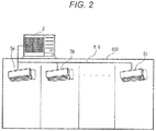
- the above-described air conditioner 1 is installed for the building 600 shown in Fig. 2 .
- the outdoor unit 2 is placed outdoors, and the indoor units 5a to 5c are installed in respective rooms inside the building.
- the outdoor unit 2 and the indoor units 5a to 5c are connected to each other via the above-described liquid pipe 8 and gas pipe 9. Parts of the liquid pipe 8 and the gas pipe 9 are buried in a wall (not illustrated) and a ceiling (not illustrated) of the building 600.
- the indoor unit 5c is installed in a position further from the outdoor unit 2 than the indoor units 5a and 5b are.
- a distance between the outdoor unit 2 and the indoor unit 5a is 1.5 m
- a distance between the outdoor unit 2 and the indoor unit 5b is 2.5 m
- a distance between the outdoor unit 2 and the indoor unit 5c is 10 m.
- a length of portions of the liquid pipe 8 and the gas pipe 9 by which the indoor unit 5c and the outdoor unit 2 are connected to each other is longer than those of the indoor units 5a and 5b.
- Fig. 1A the following describes a flow of a refrigerant in the refrigerant circuit 100 and an operation of each section while the air conditioner 1 of the present embodiment performs an air-conditioning operation.
- the following description first deals with a case where the indoor units 5a to 5c perform a cooling operation and then with a case where the indoor units 5a to 5c perform a heating operation.
- the dashed arrows indicate a flow of the refrigerant during the cooling operation
- the solid arrows indicate a flow of the refrigerant during the heating operation.
- the CPU 210 of the outdoor-unit controller 200 shifts the four-way valve 22 such that the ports a and b of the four-way valve 22 are communicated with each other and the ports c and d of the four-way valve 22 are communicated with each other, as indicated by the dashed lines. Consequently, the refrigerant circuit 100 enters a cooling cycle.
- the outdoor heat exchanger 23 serves as a condenser
- the indoor heat exchangers 51a to 51c each serve as an evaporator.
- the high-pressure refrigerant discharged from the compressor 21 flows through the discharge pipe 41, and then flows into the four-way valve 22. Furthermore, from the four-way valve 22, the refrigerant flows through the refrigerant pipe 43, and then flows into the outdoor heat exchanger 23. Thereafter, inside the outdoor heat exchanger 23, the refrigerant is subjected to heat exchange with outdoor air taken into the outdoor unit 2 by rotation of the outdoor fan 27, so that the refrigerant is condensed. The refrigerant flows out from the outdoor heat exchanger 23, and then flows through the outdoor-unit liquid pipe 44. Then, the refrigerant flows into the liquid pipe 8 via the outdoor expansion valve 24 and the closing valve 25 each of which is fully opened.
- the refrigerant flows into the indoor units 5a to 5c via the liquid-pipe connection parts 53a to 53c.
- the refrigerant that has flown into the indoor units 5a to 5c flows through the indoor-unit liquid pipes 71a to 71c, and is decompressed while flowing through the indoor expansion valves 52a to 52c.
- the refrigerant flown into the indoor heat exchangers 51a to 51c from the indoor-unit liquid pipes 71a to 71c is subjected to heat exchange with air taken into the indoor units 5a to 5c by rotation of the indoor fans 55a to 55c, so that the refrigerant is evaporated.
- the indoor heat exchangers 51a to 51c each serve as an evaporator.
- the air that has been cooled as a result of the heat exchange with the refrigerant in the indoor heat exchangers 51a to 51c is blown into the respective rooms through outlets (not illustrated). In this manner, cooling of the rooms in which the indoor units 5a to 5c are installed is performed.
- the refrigerant flows out from the indoor heat exchangers 51a to 51c, and then flows into the gas pipe 9 via the indoor-unit gas pipes 72a to 72c and the gas-pipe connection parts 54a to 54c. After flowing through the gas pipe 9, the refrigerant flows into the outdoor unit 2 via the closing valve 26.
- the refrigerant that has flown into the outdoor unit 2 flows through the outdoor-unit gas pipe 45, the four-way valve 22, the refrigerant pipe 46, the accumulator 28, and the intake pipe 42 in sequence.
- the refrigerant is then drawn into the compressor 21, and is compressed again.
- the CPU 210 of the outdoor-unit controller 200 operates the four-way valve 22 such that the ports a and d of the four-way valve 22 are communicated with each other and the ports b and c of the four-way valve 22 are communicated with each other, as indicated by the solid lines. Consequently, the refrigerant circuit 100 enters a heating cycle.
- the outdoor heat exchanger 23 serves as an evaporator
- the indoor heat exchangers 51a to 51c each serve as a condenser.
- the high-pressure refrigerant discharged from the compressor 21 flows through the discharge pipe 41, and then flows into the four-way valve 22. From the four-way valve 22, the refrigerant further flows through the outdoor-unit gas pipe 45, the closing valve 26, the gas pipe 9, and the gas-pipe connection parts 54a to 54c in sequence, and then flows into the indoor units 5a to 5c.
- the refrigerant flown into the indoor units 5a to 5c flows through the indoor-unit gas pipes 72a to 72c, and then flows into the indoor heat exchangers 51a to 51c.
- the refrigerant is subjected to heat exchange with air taken into the indoor units 5a to 5c by rotation of the indoor fans 55a to 55c, so that the refrigerant is condensed.
- the indoor heat exchangers 51a to 51c each serve as a condenser.
- the air that has been heated as a result of the heat exchange with the refrigerant in the indoor heat exchangers 51a to 51c is blown into the respective rooms through the outlets (not illustrated). In this manner, heating of the rooms in which the indoor units 5a to 5c are installed is performed.
- the refrigerant flows out from the indoor heat exchangers 51a to 51c, and then flows through the indoor-unit liquid pipes 71a to 71c. Then, the refrigerant flows through the indoor expansion valves 52a to 52c, so as to be decompressed. The refrigerant thus decompressed flows through the indoor-unit liquid pipes 71a to 71c and the liquid-pipe connection parts 53a to 53c, and then flows into the liquid pipe 8.
- the refrigerant flows into the outdoor unit 2 via the closing valve 25.
- the refrigerant that has flown into the outdoor unit 2 flows through the outdoor-unit liquid pipe 44, and is further decompressed while flowing through the outdoor expansion valve 24.
- the opening degree of the outdoor expansion valve 24 is set at a value corresponding to a discharge temperature of the compressor 21 detected by the discharge temperature sensor 33.
- the refrigerant that has flown from the outdoor-unit liquid pipe 44 into the outdoor heat exchanger 23 is subjected to heat exchange with ambient air taken into the outdoor unit 2 by rotation of the outdoor fan 27, so that the refrigerant is evaporated.
- the refrigerant flows out from the outdoor heat exchanger 23, and then flows through the refrigerant pipe 43, the four-way valve 22, the refrigerant pipe 46, the accumulator 28, and the intake pipe 42 in sequence.
- the refrigerant is then drawn into the compressor 21, and is compressed again.
- the indoor unit 5c is installed in the position further from the outdoor unit 2 than the indoor units 5a and 5b are, as described above. Namely, regarding the indoor unit 5c, a length of the portions of the liquid pipe 8 and the gas pipe 9 by which the indoor unit 5c and the outdoor unit 2 are connected to each other is longer than those of the indoor units 5a and 5b. In this case, when the air conditioner 1 performs a cooling operation or a heating operation, the following phenomenon might occur.
- the refrigerant discharged from the compressor 21 flows through the discharge pipe 41, and flows into the outdoor heat exchanger 23 therefrom via the four-way valve 22, so that the refrigerant is condensed. Furthermore, the refrigerant flows out from the outdoor unit 2, and flows into the indoor heat exchangers 51a to 51c of the indoor units 5a to 5c, so that the refrigerant is evaporated. Meanwhile, during a heating operation, a gas refrigerant discharged from the compressor 21 flows through the discharge pipe 41, and flows into the outdoor-unit gas pipe 45 therefrom via the four-way valve 22, so as to flow out from the outdoor unit 2.
- the gas refrigerant flows into the indoor heat exchangers 51a to 51c of the indoor units 5a to 5c, so that the gas refrigerant is condensed. Then, the refrigerant flows out from the indoor units 5a to 5c, and flows into the outdoor heat exchanger 23 of the outdoor unit 2, so that the refrigerant is evaporated.
- the length of the portions of the liquid pipe 8 and the gas pipe 9 by which the indoor unit 5c and the outdoor unit 2 are connected to each other is longer. Therefore, a pressure loss of the refrigerant caused by the liquid pipe 8 and the gas pipe 9 in the indoor unit 5c is greater than those in the indoor units 5a and 5b. Therefore, as compared to the indoor units 5a and 5b, the refrigerant is difficult to flow through the indoor unit 5c, whose portion of the refrigerant pipe, including the liquid pipe 8 and the gas pipe 9, for connecting the indoor unit 5c and the outdoor unit 2 is longer.
- the refrigerant is difficult to flow through the indoor unit 5c, as compared to the indoor units 5a and 5b. Therefore, as compared to the other indoor units 5a and 5b, the indoor unit 5c has a longer rise time, which is a period taken until an indoor temperature reaches a set temperature since an air-conditioning operation is started. Consequently, a feeling of discomfort may be given to a user in the room in which the indoor unit 5c is installed.
- the air conditioner 1 of the present embodiment executes a refrigerant amount balance control for reducing the difference between the rise times. Specifically, in the case where the air conditioner 1 performs a cooling operation, refrigerant superheating degrees in the refrigerant exit openings (the gas-pipe connection parts 54a to 54c) of the indoor heat exchangers 51a to 51c of the indoor units 5a to 5c are calculated periodically (for example, every 30 seconds).
- a maximum value and a minimum value of the refrigerant superheating degrees thus calculated are extracted, and an average value of these values is calculated as an average refrigerant superheating degree.
- refrigerant subcooling degrees in the refrigerant exit openings (the liquid-pipe connection parts 53a to 53c) of the indoor heat exchangers 51a to 51c of the indoor units 5a to 5c are calculated periodically (for example, every 30 seconds).
- a maximum value and a minimum value of the refrigerant subcooling degrees thus calculated are extracted, and an average value of these values is calculated as an average refrigerant subcooling degree.
- opening degrees of the indoor expansion valves 52a to 52c of the indoor units 5a to 5c are adjusted so that the refrigerant superheating degrees or the refrigerant subcooling degrees in the refrigerant exit openings of the indoor heat exchangers 51a to 51c reach the average refrigerant superheating degree or average refrigerant subcooling degree thus calculated.
- the refrigerant superheating degree of the indoor unit 5c is larger than those of the indoor units 5a and 5b during a cooling operation.
- the refrigerant superheating degree of the indoor unit 5a is three degrees
- the refrigerant superheating degree of the indoor unit 5b is five degrees
- the refrigerant superheating degree of the indoor unit 5c is 11 degrees.
- opening of the indoor expansion valves 52a and 52b is restricted (i.e., opening degrees of these valves are reduced) in the indoor units 5a and 5b, which have smaller refrigerant superheating degrees than an average refrigerant superheating degree (in this example, seven degrees, which is an average value calculated from 11 degrees (maximum value) and three degrees (minimum value)), so that the refrigerant superheating degrees are increased to the average refrigerant superheating degree.
- an average refrigerant superheating degree in this example, seven degrees, which is an average value calculated from 11 degrees (maximum value) and three degrees (minimum value)
- an opening degree of the indoor expansion valve 52c is increased in the indoor unit 5c, which has a larger refrigerant superheating degree than the average refrigerant superheating degree, so that the refrigerant superheating degree is reduced to the average refrigerant superheating degree. Note that initial opening degrees of the indoor expansion valves 52a to 52c at the time of start of the cooling operation will be described later.
- the indoor unit 5c through which the refrigerant is difficult to flow, has a larger refrigerant subcooling degree than those of the indoor units 5a and 5b.
- the refrigerant subcooling degree of the indoor unit 5a is six degrees
- the refrigerant subcooling degree of the indoor unit 5b is 10 degrees
- the refrigerant subcooling degree of the indoor unit 5c is 20 degrees.
- opening of the indoor expansion valves 52a and 52b is restricted (i.e., opening degrees of these valves are reduced) in the indoor units 5a and 5b, which have smaller refrigerant subcooling degrees than an average refrigerant subcooling degree (in this example, 13 degrees, which is an average value calculated from 20 degrees (maximum value) and six degrees (minimum value)), so that the refrigerant subcooling degrees are increased to the average refrigerant subcooling degree.
- an average refrigerant subcooling degree in this example, 13 degrees, which is an average value calculated from 20 degrees (maximum value) and six degrees (minimum value)
- an opening degree of the indoor expansion valve 52c is increased in the indoor unit 5c, which has a larger refrigerant subcooling degree than the average refrigerant subcooling degree, so that the refrigerant subcooling degree is reduced to the average refrigerant subcooling degree. Note that initial opening degrees of the indoor expansion valves 52a to 52c at the time of start of the heating operation will be described later.
- the air conditioner 1 of the present embodiment executes the refrigerant amount balance control. Consequently, opening of the indoor expansion valves 52a and 52b is restricted (i.e., the opening degrees of these valves are reduced) in the indoor units 5a and 5b, namely, an amount of refrigerant flowing through the indoor units 5a and 5b is reduced. Meanwhile, the opening degree of the indoor expansion valve 52c is increased in the indoor unit 5c, through which the refrigerant is difficult to flow. Consequently, a part of the refrigerant flown to the indoor units 5a and 5b is flown to the indoor unit 5c. This increases an amount of refrigerant flowing through the indoor unit 5c. This shortens a rise time of the indoor unit 5c, the rise time being a period taken until an indoor temperature reaches a set temperature since an air-conditioning operation is started.
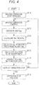
- FIG. 3 shows a flow of processes related to a control performed by the CPU 210 of the outdoor-unit controller 200 in the case where the air conditioner 1 performs the cooling operation.
- Fig. 4 shows a flow of processes related to a control performed by the CPU 210 of the outdoor-unit controller 200 in the case where the air conditioner 1 performs the heating operation.
- the letters "ST" indicates a step, and a number following the letters "ST" indicates a step number. Note that Figs. 3 and 4 each show processes related to the refrigerant amount balance control.
- Examples of the general processes encompass a control of the refrigerant circuit 100 for an operation condition such as a set temperature and/or an airflow rate according to an instruction given by a user.
- the description below deals with, as an example, a case where all of the indoor units 5a to 5c perform a cooling operation or a heating operation.
- the reference sign “Pl” denotes an intake pressure of the compressor 21 that is detected by the intake pressure sensor 32 of the outdoor unit 2 during a control for a cooling operation.
- the reference sign “Tls” denotes a low pressure saturation temperature that is calculated from an intake pressure Pl.
- the reference sign “Toc” denotes heat exchange outlet temperatures that are detected by the gas-side temperature sensors 62a to 62c of the indoor units 5a to 5c (when the description individually refers to the indoor units 5a to 5c, the heat exchange outlet temperatures thereof are respectively denoted as “Toca” to "Tocc”).
- the reference sign "SH” denotes refrigerant superheating degrees in the refrigerant exit openings of the indoor heat exchangers 51a to 51c, each of the refrigerant superheating degrees being obtained by subtracting the low pressure saturation temperature Tls from the heat exchange outlet temperature Toc (when the description individually refers to the indoor units 5a to 5c, the refrigerant superheating degrees thereof are respectively denoted as “SHa” to "SHc”).
- the reference sign “SHv” denotes an average refrigerant superheating degree that is calculated from a maximum value and a minimum value of the refrigerant superheating degrees SH of the indoor units 5a to 5c.
- the reference sign “Ph” denotes a discharge pressure of the compressor 21 that is detected by the discharge pressure sensor 31 of the outdoor unit 2 during a control for a heating operation.
- the reference sign “Ths” denotes a high pressure saturation temperature calculated from the discharge pressure Ph.
- the reference sign “Tow” denotes heat exchange outlet temperatures detected by the liquid-side temperature sensors 61a to 61c of the indoor units 5a to 5c (when the description individually refers to the indoor units 5a to 5c, the heat exchange outlet temperatures thereof are respectively denoted as “Towa” to “Towc”).
- the reference sign "SC” denotes refrigerant subcooling degrees in the refrigerant exit openings of the indoor heat exchangers 51a to 51c, each of the refrigerant subcooling degrees being obtained by subtracting the heat exchange outlet temperature Tow from the high pressure saturation temperature Ths (when the description individually refers to the indoor units 5a to 5c, the refrigerant subcooling degrees thereof are respectively denoted as “SCa” to “SCc”).
- the reference sign “SCv” denotes an average refrigerant subcooling degree that is calculated from a maximum value and a minimum value of the refrigerant subcooling degrees SC of the indoor units 5a to 5c.
- the CPU 210 executes a cooling operation start process (ST1).
- the cooling operation start process refers to a process in which the CPU 210 operates the four-way valve 22 for causing the refrigerant circuit 100 to enter a cooling cycle.
- the cooling operation start process is performed when the cooling operation is performed at first.
- the CPU 210 performs a control for the cooling operation (ST2).
- the CPU 210 starts the compressor 21 and the outdoor fan 27 at the number of rotations according to a required capacity from the indoor units 5a to 5c.
- the CPU 210 obtains, via the sensor input section 240, a discharge temperature of the compressor 21 detected by the discharge temperature sensor 33. According to the discharge temperature thus obtained, the CPU 210 adjusts an opening degree of the outdoor expansion valve 24.
- the CPU 210 transmits, to the indoor units 5a to 5c via the communication section 230, an operation start signal for starting the cooling operation.
- the CPUs 510a to 510c of the indoor-unit controllers 500a to 500c of the indoor units 5a to 5c receive the operation start signal via the communication sections 530a to 530c.
- the CPUs 510a to 510c each start a respective one of the indoor fans 55a to 55c at the number of rotations according to an instruction as to an airflow rate given by a user.
- the CPUs 510a to 510c adjust opening degrees of the indoor expansion valves 52a to 52c so that refrigerant superheating degrees SH in the refrigerant exit openings (the gas-pipe connection parts 54a to 54c) of the indoor heat exchangers 51a to 51c reach a target refrigerant superheating degree for operation start (for example, three degrees).
- the target refrigerant superheating degree for operation start is calculated by, e.g., a test performed preliminarily, and is stored in the storage sections 520a to 520c.
- the target refrigerant superheating degree for operation start is a value that is verified to allow each of the indoor units to exert an adequate cooling capacity.
- the CPUs 510a to 510c adjust the opening degrees of the indoor expansion valves 52a to 52c so that the refrigerant superheating degrees SH reach the above-described target refrigerant superheating degree for operation start.
- the CPU 210 obtains, via the sensor input section 240, an intake pressure PI detected by the intake pressure sensor 32 (ST3). Furthermore, the CPU 210 obtains heat exchange outlet temperatures Toc (Toca to Tocc) from the indoor units 5a to 5c via the communication section 230 (ST3). Note that the CPUs 510a to 510c obtain detection values detected by the gas-side temperature sensors 62a to 62c of the indoor units 5a to 5c, and transmit the detection values to the outdoor unit 2 via the communication sections 530a to 530c as the heat exchange outlet temperatures Toc. The detection values are obtained by the CPUs at every predetermined period (for example, every 30 seconds), and are stored in the storage sections.
- the CPU 210 calculates a low pressure saturation temperature Tls from the intake pressure Pl obtained in ST3 (ST4).
- the CPU 210 calculates refrigerant superheating degrees SH of the indoor units 5a to 5c from the low pressure saturation temperature Tls thus calculated and the heat exchange outlet temperatures Toc obtained in ST3 (ST5).
- the CPU 210 calculates an average refrigerant superheating degree SHv from the refrigerant superheating degrees SH of the indoor units 5a to 5c calculated in ST5 (ST6). Specifically, the CPU 210 extracts a maximum value and a minimum value of the refrigerant superheating degrees SHa to SHc of the indoor units 5a to 5c, and calculates an average value of these values. The CPU 210 deals with the calculation result as the average refrigerant superheating degree SHv.
- the CPU 210 transmits, to the indoor units 5a to 5c via the communication section 230, the average refrigerant superheating degree SHv calculated in ST6 and the low pressure saturation temperature Tls calculated in ST4 (ST7).
- the CPUs 510a to 510c of the indoor units 5a to 5c receive the average refrigerant superheating degree SHv and the low pressure saturation temperature Tls via the communication sections 530a to 530c.
- the CPUs 510a to 510c each subtract, from a respective one of the heat exchange outlet temperatures Toca to Tocc detected by the gas-side temperature sensors 62a to 62c, the low pressure saturation temperature Tls that has been received from the outdoor unit 2.
- the CPUs 510a to 510c calculate the refrigerant superheating degrees SHa to SHc.
- the CPUs 510a to 510c adjust the opening degrees of the indoor expansion valves 52a to 52c so that the refrigerant superheating degrees SHa to SHc thus calculated reach the average refrigerant superheating degree SHv received from the outdoor unit 2.
- the above-described processes from ST3 to ST7 are the processes related to the refrigerant amount balance control performed during the cooling operation according to the present embodiment.
- the CPU 210 determines the presence or absence of an operation stop instruction given by the user (ST8).
- the operation stop instruction instructs all the indoor units 5a to 5c to stop the operation. If the presence of the operation stop instruction is determined (ST8 - Yes), the CPU 210 executes an operation stop process (ST9), so that the process is ended.
- the CPU 210 stops the compressor 21 and the outdoor fan 27, and causes the outdoor expansion valve 24 to be fully closed.
- the CPU 210 transmits, to the indoor units 5a to 5c via the communication section 230, an operation stop signal for stopping the operation.
- the CPUs 510a to 510c of the indoor units 5a to 5c receive the operation stop signal via the communication sections 530a to 530c.
- the CPUs 510a to 510c stop the indoor fans 55a to 55c, and cause the indoor expansion valves 52a to 52c to be fully closed.
- the CPU 210 executes a heating operation start process (ST10).
- the heating operation start process refers to a process in which the CPU 210 operates the four-way valve 22 for causing the refrigerant circuit 100 to enter a heating cycle. The heating operation start process is performed when the heating operation is performed at first.
- the CPU 210 performs a control for the heating operation (ST11).
- the CPU 210 starts the compressor 21 and the outdoor fan 27 at the number of rotations according to a required capacity from the indoor units 5a to 5c.
- the CPU 210 obtains, via the sensor input section 240, a discharge temperature of the compressor 21 detected by the discharge temperature sensor 33. According to the discharge temperature thus obtained, the CPU 210 adjusts an opening degree of the outdoor expansion valve 24.
- the CPU 210 transmits, to the indoor units 5a to 5c via the communication section 230, an operation start signal for starting the heating operation.
- the CPUs 510a to 510c of the indoor-unit controllers 500a 500c of the indoor units 5a to 5c receive the operation start signal via the communication sections 530a to 530c.
- the CPUs 510a to 510c each start a respective one of the indoor fans 55a to 55c at the number of rotations according to an instruction as to an airflow rate given by a user.
- the CPUs 510a to 510c adjust opening degrees of the indoor expansion valves 52a to 52c so that refrigerant subcooling degrees SC in the refrigerant exit openings (the liquid-pipe connection parts 53a to 53c) of the indoor heat exchangers 51a to 51c reach a target refrigerant subcooling degree for operation start (for example, six degrees).
- the target refrigerant subcooling degree for operation start is calculated by, e.g., a test performed preliminarily, and is stored in the storage sections 520a to 520c.
- the target refrigerant superheating degree for operation start is a value that is verified to allow each of the indoor units to exert an adequate heating capacity.
- the CPUs 510a to 510c adjust the opening degrees of the indoor expansion valves 52a to 52c so that the refrigerant subcooling degrees SC reach the above-described target refrigerant subcooling degree for operation start.
- the CPU 210 obtains, via the sensor input section 240, a discharge pressure Ph detected by the discharge pressure sensor 31 (ST12). Furthermore, the CPU 210 obtains heat exchange outlet temperatures Tow (Towa to Towc) from the indoor units 5a to 5c via the communication section 230 (ST12). Note that the CPUs 510a to 510c obtain, as the heat exchange outlet temperatures Tow, detection values detected by the liquid-side temperature sensors 61a to 61c in the indoor units 5a to 5c, and transmit the detection values to the outdoor unit 2 via the communication sections 530a to 530c. The above-described detection values are obtained by the CPUs at every predetermined period (for example, every 30 seconds), and are stored in the storage sections.
- the CPU 210 calculates a high pressure saturation temperature Ths from the discharge pressure Ph obtained in ST12 (ST13).
- the CPU 210 calculates refrigerant subcooling degrees SC of the indoor units 5a to 5c from the high pressure saturation temperature Ths thus calculated and the heat exchange outlet temperatures Tow obtained in ST12 (ST14).
- the CPU 210 calculates an average refrigerant subcooling degree SCv from the refrigerant subcooling degrees SC of the indoor units 5a to 5c calculated in ST14 (ST15). Specifically, the CPU 210 extracts a maximum value and a minimum value of the refrigerant subcooling degrees SCa to SCc of the indoor units 5a to 5c, and calculates an average value of these values. The CPU 210 deals with the calculation result as the average refrigerant subcooling degree SCv.
- the CPU 210 transmits, to the indoor units 5a to 5c via the communication section 230, the average refrigerant subcooling degree SCv calculated in ST15 and the high pressure saturation temperature Ths calculated in ST13 (ST16).
- the CPUs 510a to 510c of the indoor units 5a to 5c receive the average refrigerant subcooling degree SCv and the high pressure saturation temperature Ths via the communication sections 530a to 530c.
- the CPUs 510a to 510c each subtract, from the high pressure saturation temperature Ths received from the outdoor unit 2, a respective one of the heat exchange outlet temperatures Towa to Towc detected by the liquid-side temperature sensors 61a to 61c.
- the CPUs 510a to 510c calculate the refrigerant subcooling degrees SCa to SCc.
- the CPUs 510a to 510c adjust the opening degrees of the indoor expansion valves 52a to 52c so that the refrigerant subcooling degrees SCa to SCc thus calculated reach the average refrigerant subcooling degree SCv received from the outdoor unit 2.
- the above-described processes from ST12 to ST16 are the processes related to the refrigerant amount balance control performed during the heating operation according to the present embodiment.
- the air conditioner 1 executes the refrigerant amount balance control for adjusting the opening degrees of the indoor expansion valves 52a to 52c so that the refrigerant superheating degrees SHa to SHc of the indoor units 5a to 5c reach the average refrigerant superheating degree SHv that is calculated from the maximum value and the minimum value of the refrigerant superheating degrees SHa to SHc.
- the air conditioner 1 executes the refrigerant amount balance control for adjusting the opening degrees of the indoor expansion valves 52a to 52c so that the refrigerant subcooling degrees SCa to SCc of the indoor units 5a to 5c reach the average refrigerant subcooling degree SCv that is calculated from the maximum value and the minimum value of the refrigerant subcooling degrees SCa to SCc. Consequently, in a case where there exists an indoor unit through which a refrigerant is difficult to flow, it is possible to shorten a rise time of the indoor unit, the rise time being a period taken until an indoor temperature reaches a set temperature since an air-conditioning operation is started. This reduces the difference between the rise times of the indoor units.
- installation conditions of the indoor units 5a to 5c are defined such that the lengths of the portions of the refrigerant pipe, including the liquid pipe 8 and the gas pipe 9, of the indoor units 5a to 5c are different from each other.
- the lengths of the portions of the refrigerant pipe are different from each other, and therefore there exists an indoor unit through which a refrigerant is difficult to flow.
- the present disclosure is not limited to this.
- the refrigerant amount balance control may be executed also in a case where there exists, among the indoor units 5a to 5c, an indoor unit through which a refrigerant is difficult to flow due to a difference between the indoor heat exchangers of the indoor units 5a to 5c.
- an indoor unit 5c includes an indoor heat exchanger larger than those of the other indoor units 5a and 5b, and thus the indoor heat exchanger of the indoor unit 5c has a path longer than those of the other indoor units 5a and 5b.
- an indoor unit 5c includes an indoor heat exchanger having a different shape from those of the other indoor units 5a and 5b, and thus the indoor heat exchanger of the indoor unit 5c has a path whose number of turnings is larger than those of the other indoor units 5a and 5b.
- a pressure loss caused by the path of the indoor heat exchanger of the indoor unit 5c is greater than those of the other indoor units 5a and 5b. Consequently, the refrigerant is difficult to flow through the indoor unit 5c, as compared to the other indoor units 5a and 5b. Therefore, the indoor unit 5c has a longer rise time taken until an indoor temperature reaches a set temperature since an air-conditioning operation is started, as compared to the other indoor units 5a and 5b.
- opening of the indoor expansion valves 52a and 52b is restricted (i.e., opening degrees of these valves are reduced) in the indoor units 5a and 5b, namely, an amount of refrigerant flowing through the indoor units 5a and 5b is reduced.
- an opening degree of the indoor expansion valve 52c is increased in the indoor unit 5c, through which the refrigerant is difficult to flow. Consequently, a part of the refrigerant flown to the indoor units 5a and 5b is flown to the indoor unit 5c, thereby increasing an amount of refrigerant flowing through the indoor unit 5c.
- the indoor units 5a to 5c include, in their insides, the indoor expansion valves 52a to 52c. However, it is only necessary for the indoor expansion valves 52a to 52c to be respectively provided to the indoor units 5a to 5c. For example, the indoor expansion valves 52a to 52c may be provided outside the indoor units 5a to 5c.
- the CPU 210 and the CPUs 510a to 510c execute the refrigerant amount balance control when the indoor units 5a to 5c have respective different rise times, each of which is a period taken until an indoor temperature reaches a set temperature since an air-conditioning operation is started.
- the CPU 210 and the CPUs 510a to 510c may execute the refrigerant amount balance control at any timing.
- the CPU 210 and the CPUs 510a to 510c calculate the average value of the refrigerant superheating degrees in the refrigerant exit openings of the indoor heat exchangers 51a to 51c or the average value of the refrigerant subcooling degrees in the refrigerant exit openings of the indoor heat exchangers 51a to 51c, and adjust the opening degrees of the indoor expansion valves 52a to 52c so that the refrigerant superheating degrees in the refrigerant exit openings of the indoor heat exchangers 51a to 51c reach the average value or the refrigerant subcooling degrees in the refrigerant exit openings of the indoor heat exchangers 51a to 51c reach the average value.
- the present disclosure is not limited to this.
- the CPU 210 and the CPUs 510a to 510c may adjust the opening degrees of the indoor expansion valves 52a to 52c so that the refrigerant superheating degrees in the refrigerant exit openings of the indoor heat exchangers 51a to 51c become equal to each other or the refrigerant subcooling degrees in the refrigerant exit openings of the indoor heat exchangers 51a to 51c become equal to each other.
- the CPU 210 and the CPUs 510a to 510c adjust the opening degrees of the indoor expansion valves 52a to 52c based on the refrigerant superheating degrees in the refrigerant exit openings of the indoor heat exchangers 51a to 51c or the refrigerant subcooling degrees in the refrigerant exit openings of the indoor heat exchangers 51a to 51c.
- the present disclosure is not limited to this.
- the CPU 210 and the CPUs 510a to 510c may adjust the opening degrees of the indoor expansion valves 52a to 52c based on operation state amounts with which the indoor heat exchangers 51a to 51c of the indoor units 5a to 5c exert heat exchange amounts.
- the operation state amounts encompass, for example, refrigerant superheating degrees in the refrigerant exit openings of the indoor heat exchangers 51a to 51c, refrigerant subcooling degrees in the refrigerant exit openings of the indoor heat exchangers 51a to 51c, refrigerant pressures in the refrigerant exit openings of the indoor heat exchangers 51a to 51c, refrigerant temperatures in the refrigerant exit openings of the indoor heat exchangers 51a to 51c, and differences between a saturation temperature (for example, a low pressure saturation temperature or a high pressure saturation temperature) and refrigerant temperatures in the refrigerant exit openings of the indoor heat exchangers 51a to 51c of the indoor units 5a to 5c.
- a saturation temperature for example, a low pressure saturation temperature or a high pressure saturation temperature
- the above-described heat exchange amounts correspond to air-conditioning capacities of the indoor units 5a to 5c.
- the air-conditioning capacities are calculated, for example, based on a difference between an indoor temperature and an evaporation temperature (or a condensation temperature), airflow rates of the indoor fans 55a to 55c, and superheating degrees (or subcooling degrees).
- the refrigerant amount balance control is performed by the CPU 210 and the CPUs 510a to 510c in collaboration.
- the present disclosure is not limited to this.
- the air conditioner 1 may perform the refrigerant amount balance control by a single controller. In such a case, the controller controls the members of the outdoor unit 2 and the indoor units 5a to 5c.
- the present disclosure can be said to relate to an air conditioner in which at least one outdoor unit is connected to a plurality of indoor units via a refrigerant pipe.
- An embodiment of the present disclosure may be a first or second air conditioner below.
- the first air conditioner is an air conditioner including: an outdoor unit including a compressor, a four-way valve, an outdoor heat exchanger, and an outdoor expansion valve; a plurality of indoor units respectively including indoor heat exchangers and indoor expansion valves; and a controller for controlling opening degrees of the indoor expansion valves based on refrigerant superheating degrees in refrigerant exit openings of the indoor heat exchangers during a cooling operation or refrigerant subcooling degrees in refrigerant exit openings of the indoor heat exchangers during a heating operation, wherein in a case where the indoor units have respective different rise times, each of which is a period taken until an indoor temperature reaches a set temperature since an air-conditioning operation is started, the controller executes a refrigerant amount balance control, the refrigerant amount balance control during a cooling operation calculating an average value of the refrigerant superheating degrees from a maximum value and a minimum value of the refrigerant superheating degrees in the refrigerant exit openings of the indoor heat exchangers
- the second air conditioner includes: an outdoor unit including a compressor; a plurality of indoor units respectively including indoor heat exchangers; expansion valves respectively provided to the indoor units, the expansion valves adjusting flow rates of a refrigerant in the indoor heat exchangers; and a controller for executing a refrigerant amount balance control for adjusting opening degrees of the expansion valves so that differences between a saturation temperature (for example, a low pressure saturation temperature or a high pressure saturation temperature) and refrigerant temperatures in refrigerant exit openings of the indoor heat exchangers of the indoor units become equal to each other.
- a saturation temperature for example, a low pressure saturation temperature or a high pressure saturation temperature
Abstract
Description
- This application claims priority from Japanese Patent Application No.
2016-134844 - Embodiments of the present disclosure relate to an air conditioner.
- Typically, in an air conditioner including an outdoor unit and an indoor unit that are connected to each other via a liquid pipe and a gas pipe, an opening degree of an expansion valve is controlled so that a refrigerant subcooling degree or a refrigerant superheating degree in a refrigerant exit opening of an indoor heat exchanger of the indoor unit reaches a predetermined target value. For example, an air conditioner described in
JP-A-2011-007482 - Incidentally, in the air conditioner described in
JP-A-2011-007482 - An air conditioner includes: an outdoor unit; a plurality of indoor units respectively including indoor heat exchangers; expansion valves respectively provided to the plurality of indoor units, the expansion valves being configured to adjust flow rates of a refrigerant in the indoor heat exchangers; and a controller for executing a refrigerant amount balance control for adjusting opening degrees of the expansion valves so that operation state amounts, with which the indoor heat exchangers exert heat exchange amounts, of the plurality of indoor units become equal to each other.
-
-
Fig. 1A is a refrigerant circuit diagram of an air conditioner according to an embodiment of the present disclosure, andFig. 1B is a block diagram of an outdoor-unit controller and an indoor-unit controller of the air conditioner; -
Fig. 2 shows an installation layout of indoor units and an outdoor unit according to the embodiment of the present disclosure; -
Fig. 3 is a flowchart illustrating processes of a cooling operation performed by the outdoor-unit controller according to the embodiment of the present disclosure; and -
Fig. 4 is a flowchart illustrating processes of a heating operation performed by the outdoor-unit controller according to the embodiment of the present disclosure. - In the following detailed description, for purpose of explanation, numerous specific details are set forth in order to provide a thorough understanding of the disclosed embodiments. It will be apparent, however, that one or more embodiments may be practiced without these specific details. In other instances, well-known structures and devices are schematically shown in order to simplify the drawing.
- In the air conditioner in which the one outdoor unit is connected to the plurality of indoor units via the refrigerant pipe, during an air-conditioning operation, there might exist an indoor unit through which a refrigerant is difficult to flow, as compared to the other indoor units. For example, among the plurality of indoor units, there is an indoor unit that is installed in a position further from the outdoor unit than the other indoor units are. A portion of a refrigerant pipe via which such an indoor unit and the outdoor unit are connected to each other is longer than those of the other indoor units. Therefore, a pressure loss that is caused by the refrigerant pipe and affects the indoor unit is greater than those of the other indoor units. Consequently, the refrigerant is difficult to flow through the indoor unit that is installed in the position further from the outdoor unit than the other indoor units are. Furthermore, among the plurality of indoor units, there might exist an indoor unit including an indoor heat exchanger larger than those of the other indoor units. In such an indoor unit, the indoor heat exchanger might have a path longer than those in the other indoor units. Moreover, among the plurality of indoor units, there might exist an indoor unit including an indoor heat exchanger having a different shape from those of the other indoor units. In such an indoor unit, the indoor heat exchanger might have a path whose number of turnings is larger than those in the other indoor units. In the indoor unit including the indoor heat exchanger having a path longer than those in the other indoor units or a path whose number of turnings is larger than those in the other indoor units, a pressure loss caused by the path is greater than those in the other indoor units, and thus a refrigerant is difficult to flow through the path.
- In the above case where there exists, among the plurality of indoor units, an indoor unit through which a refrigerant is difficult to flow since an installment conditions and/or an indoor heat exchanger of the indoor unit is different from those of the other indoor units, a rise time of the indoor unit is longer than those of the other indoor units, the rise time being a period taken until an indoor temperature reaches a set temperature since an air-conditioning operation is started. Namely, the indoor units have respective different rise times, each of which is a period taken until the indoor temperature reaches the set temperature. Especially, the indoor unit having a long rise time, which is the period taken until the indoor temperature reaches the set temperature, may give a feeling of discomfort to a user in a room in which this indoor unit is installed.
- An object of the present disclosure is to provide an air conditioner that is capable of reducing a difference between rise times of a plurality of indoor units if the difference exists, each of the rise times being a period taken until an indoor temperature reaches a set temperature.
- An air conditioner according to an aspect of the present disclosure (the present air conditioner) includes: an outdoor unit; a plurality of indoor units respectively including indoor heat exchangers; expansion valves respectively provided to the plurality of indoor units, the expansion valves being configured to adjust flow rates of a refrigerant in the indoor heat exchangers; and a controller for executing a refrigerant amount balance control for adjusting opening degrees of the expansion valves so that operation state amounts, with which the indoor heat exchangers exert heat exchange amounts, of the plurality of indoor units become equal to each other.
- In the present air conditioner, the operation state amounts may be refrigerant superheating degrees in refrigerant exit openings of the indoor heat exchangers during a cooling operation.
- In this case, the controller may calculate an average value of the refrigerant superheating degrees from a maximum value and a minimum value of the refrigerant superheating degrees of the plurality of indoor units, and adjusts the opening degrees of the expansion valves so that the refrigerant superheating degrees of the plurality of indoor units reach the average value.
- In the present air conditioner, the operation state amounts may be refrigerant subcooling degrees in refrigerant exit openings of the indoor heat exchangers during a heating operation.
- In this case, the controller may calculate an average value of the refrigerant subcooling degrees from a maximum value and a minimum value of the refrigerant subcooling degrees of the plurality of indoor units, and adjusts the opening degrees of the expansion valves so that the refrigerant subcooling degrees of the plurality of indoor units reach the average value.
- In the present air conditioner, the expansion valves may be disposed inside the indoor units.
- In the present air conditioner, the controller may execute the refrigerant amount balance control in a case where the plurality of indoor units has respective different rise times, each of which is a period taken until an indoor temperature reaches a set temperature since an air-conditioning operation is started.
- According to the present air conditioner, for example, it is possible to reduce a difference between rise times of the indoor units if the difference exists, each of the rise times being a period taken until an indoor temperature reaches a set temperature.
- With reference to the drawings, the following provides a detailed description of embodiments of the present disclosure. In an air conditioner according to an embodiment of the present disclosure, one outdoor unit installed outside a building is connected in parallel to three indoor units installed inside the building. By using all of the indoor units at once, a cooling operation or a heating operation can be performed. Note that aspects of the present disclosure are not limited to the below-described embodiments. The aspects of the present disclosure may be altered in various ways within a gist of the present disclosure.
- As shown in
Figs. 1A and2 , an air conditioner 1 of to the present embodiment includes oneoutdoor unit 2 and threeindoor units 5a to 5c. Theoutdoor unit 2 is installed outside abuilding 600, which is a single-story building. Theindoor units 5a to 5c are installed indoors, and are connected in parallel to theoutdoor unit 2 via a pipe including aliquid pipe 8 and agas pipe 9. Specifically, one end of theliquid pipe 8 is connected to aclosing valve 25 of theoutdoor unit 2. The other end of theliquid pipe 8 is branched so as to be connected to liquid-pipe connection parts 53a to 53c of theindoor units 5a to 5c. Meanwhile, one end of thegas pipe 9 is connected to aclosing valve 26 of theoutdoor unit 2. The other end of thegas pipe 9 is branched so as to be connected respectively to gas-pipe connection parts 54a to 54c of theindoor units 5a to 5c. Arefrigerant circuit 100 of the air conditioner 1 is configured as above. - First, the
outdoor unit 2 will be described. Theoutdoor unit 2 includes acompressor 21, a four-way valve 22, anoutdoor heat exchanger 23, anoutdoor expansion valve 24, the closingvalve 25 to which the one end of theliquid pipe 8 is connected, the closingvalve 26 to which the one end of thegas pipe 9 is connected, anaccumulator 28, and anoutdoor fan 27. These members except for theoutdoor fan 27 are connected to each other via a refrigerant pipe (described in detail later), so that an outdoor-unit refrigerant circuit 20, which is a part of therefrigerant circuit 100, is constituted. - The
compressor 21 is a capacity-variable type compressor. Namely, thecompressor 21 is driven by a motor (not illustrated) whose number of rotations is controlled by an inverter. Thus, an operation capacity of thecompressor 21 can be changed. A refrigerant discharge side of thecompressor 21 is connected to a port a of the four-way valve 22 (described later) via adischarge pipe 41. Meanwhile, a refrigerant intake side of thecompressor 21 is connected to a refrigerant outflow side of theaccumulator 28 via anintake pipe 42. - The four-
way valve 22 is a valve for changing a flow direction of the refrigerant. The four-way valve 22 has four ports a, b, c, and d. As described above, the port a is connected to the refrigerant discharge side of thecompressor 21 via thedischarge pipe 41. The port b is connected to one refrigerant entry/exit opening of theoutdoor heat exchanger 23 via arefrigerant pipe 43. The port c is connected to a refrigerant inflow side of theaccumulator 28 via arefrigerant pipe 46. The port d is connected to the closingvalve 26 via an outdoor-unit gas pipe 45. - The
outdoor heat exchanger 23 performs heat exchange between the refrigerant and ambient air that has been taken into theoutdoor unit 2 by rotation of the outdoor fan 27 (describer later). As described above, the one refrigerant entry/exit opening of theoutdoor heat exchanger 23 is connected to the port b of the four-way valve 22 via therefrigerant pipe 43. The other refrigerant entry/exit opening of theoutdoor heat exchanger 23 is connected to the closingvalve 25 via an outdoor-unit liquid pipe 44. - The
outdoor expansion valve 24 is provided in the outdoor-unit liquid pipe 44. Theoutdoor expansion valve 24 is an electronic expansion valve. Adjusting an opening degree of theoutdoor expansion valve 24 adjusts an amount of refrigerant flown into theoutdoor heat exchanger 23 or an amount of refrigerant flown from theoutdoor heat exchanger 23. While the air conditioner 1 performs a cooling operation, the opening degree of theoutdoor expansion valve 24 is in a fully opened state. Meanwhile, while the air conditioner 1 performs a heating operation, the opening degree of theoutdoor expansion valve 24 is controlled according to a discharge temperature of thecompressor 21 detected by a discharge temperature sensor 33 (described later) so that that the discharge temperature does not exceed a capacity upper limit value. - The
outdoor fan 27 is made of a resin material, and is positioned near theoutdoor heat exchanger 23. Theoutdoor fan 27 is rotated by a fan motor (not illustrated). Consequently, ambient air is taken into theoutdoor unit 2 through an inlet (not illustrated). Furthermore, the ambient air having been subjected to the heat exchange with the refrigerant in theoutdoor heat exchanger 23 is discharged to the outside of theoutdoor unit 2 through an outlet (not illustrated). - As described above, the refrigerant inflow side of the
accumulator 28 is connected to the port c of the four-way valve 22 via therefrigerant pipe 46. The refrigerant outflow side of theaccumulator 28 is connected to the refrigerant intake side of thecompressor 21 via theintake pipe 42. Theaccumulator 28 separates, into a gas refrigerant and a liquid refrigerant, the refrigerant flown into theaccumulator 28 from therefrigerant pipe 46, and sends the gas refrigerant to thecompressor 21. - In addition to the above-described members, the
outdoor unit 2 includes various sensors. As shown inFig. 1A , thedischarge pipe 41 includes adischarge pressure sensor 31 and thedischarge temperature sensor 33. Thedischarge pressure sensor 31 detects a discharge pressure, which is a pressure of the refrigerant discharged from thecompressor 21. Thedischarge temperature sensor 33 detects a temperature of the refrigerant discharged from thecompressor 21. In therefrigerant pipe 46 and near a refrigerant inflow opening of theaccumulator 28, anintake pressure sensor 32 and anintake temperature sensor 34 are provided. Theintake pressure sensor 32 detects a pressure of the refrigerant that is to be taken into thecompressor 21. Theintake temperature sensor 34 detects a temperature of the refrigerant that is to be taken into thecompressor 21. - In the outdoor-
unit liquid pipe 44 and between theoutdoor heat exchanger 23 and theoutdoor expansion valve 24, a heatexchange temperature sensor 35 is provided. The heatexchange temperature sensor 35 detects a temperature of the refrigerant that is to be flown into theoutdoor heat exchanger 23 or a temperature of the refrigerant that is flown from theoutdoor heat exchanger 23. Furthermore, near the inlet (not illustrated) of theoutdoor unit 2, an ambientair temperature sensor 36 is provided. The ambientair temperature sensor 36 detects a temperature of ambient air flown into theoutdoor unit 2, i.e., an ambient air temperature. - Furthermore, the
outdoor unit 2 includes an outdoor-unit controller 200. The outdoor-unit controller 200 is mounted on a control board accommodated in an electrical equipment box (not illustrated) of theoutdoor unit 2. As shown inFig. 1B , the outdoor-unit controller 200 includes aCPU 210, astorage section 220, acommunication section 230, and asensor input section 240. - The
storage section 220 includes a ROM and a RAM. Thestorage section 220 stores a control program for theoutdoor unit 2, detection values corresponding to detection signals from the various sensors, control states of thecompressor 21 and theoutdoor fan 27, and the like. Thecommunication section 230 is an interface for performing communication with theindoor units 5a to 5c. Thesensor input section 240 obtains detection results of the various sensors in theoutdoor unit 2, and outputs the detection results to theCPU 210. - The
CPU 210 obtains the above-described detection results of the various sensors in theoutdoor unit 2 via thesensor input section 240. Furthermore, theCPU 210 obtains control signals from theindoor units 5a to 5c via thecommunication section 230. Based on the detection results and the control signals thus obtained, theCPU 210 controls driving of thecompressor 21 and theoutdoor fan 27. Furthermore, based on the detection results and the control signals thus obtained, theCPU 210 controls shifting of the four-way valve 22. Moreover, based on the detection results and the control signals thus obtained, theCPU 210 adjusts the opening degree of theoutdoor expansion valve 24. - Next, the three
indoor units 5a to 5c will be described. The threeindoor units 5a to 5c respectively includeindoor heat exchangers 51a to 51c,indoor expansion valves 52a to 52c, the liquid-pipe connection parts 53a to 53c to which the branches of the other end of theliquid pipe 8 are connected, the gas-pipe connection parts 54a to 54c to which the branches of the other end of thegas pipe 9 are connected, andindoor fans 55a to 55c. Theindoor heat exchangers 51a to 51c, theindoor expansion valves 52a to 52c, the liquid-pipe connection parts 53a to 53c, and the gas-pipe connection parts 54a to 54c are connected to each other respectively via refrigerant pipes (described in detail later), so that indoor-unit refrigerant circuits 50a to 50c, each of which is a part of therefrigerant circuit 100, are constituted. Note that the threeindoor units 5a to 5c have identical capacities. If refrigerant superheating degrees in refrigerant exit openings of theindoor heat exchangers 51a to 51c during a cooling operation are set at a predetermined value (for example, five degrees) or less, each of theindoor units 5a to 5c can exert an adequate cooling capacity. Meanwhile, if refrigerant subcooling degrees in refrigerant exit openings of theindoor heat exchangers 51a to 51c during a heating operation are set at a predetermined value (for example, 10 degrees) or less, each of theindoor units 5a to 5c can exert an adequate heating capacity. Note that each of the above-described refrigerant superheating degree and refrigerant subcooling degree corresponds to an operation state amount of the present disclosure. - Note that the
indoor units 5a to 5c have identical configurations. Therefore, the following description will deal with a configuration of theindoor unit 5a, and descriptions about the otherindoor units Figs. 1A and 1B , members of theindoor unit 5b corresponding to members of theindoor unit 5a are given reference signs of the corresponding members of theindoor unit 5a whose final letters "a" have been replaced with "b". Similarly, members of theindoor unit 5c corresponding to members of theindoor unit 5a are given reference signs of the corresponding members of theindoor unit 5a whose final letters "a" have been replaced with "c". - The
indoor heat exchanger 51a performs heat exchange between the refrigerant and indoor air that has been taken into theindoor unit 5a through an inlet (not illustrated) by rotation of anindoor fan 55a (described later). One refrigerant entry/exit opening of theindoor heat exchanger 51a is connected to the liquid-pipe connection part 53a via an indoor-unit liquid pipe 71a. The other refrigerant entry/exit opening of theindoor heat exchanger 51a is connected to the gas-pipe connection part 54a via an indoor-unit gas pipe 72a. While theindoor unit 5a performs a cooling operation, theindoor heat exchanger 51a serves as an evaporator. While theindoor unit 5a performs a heating operation, theindoor heat exchanger 51a serves as a condenser. - Note that the liquid-
pipe connection part 53a and the gas-pipe connection part 54a are connected to the refrigerant pipe by welding, a flare nut, and/or the like. - The
indoor expansion valve 52a is provided in the indoor-unit liquid pipe 71a. Theindoor expansion valve 52a is an electronic expansion valve. Theindoor expansion valve 52a adjusts a flow rate of the refrigerant of theindoor heat exchanger 51a. In a case where theindoor heat exchanger 51a serves as an evaporator (i.e., in a case where theindoor unit 5a performs a cooling operation), the opening degree of theindoor expansion valve 52a is adjusted so that the refrigerant superheating degree in the refrigerant exit opening (the gas-pipe connection part 54a) of theindoor heat exchanger 51a reaches an average refrigerant superheating degree (described later). Meanwhile, in a case where theindoor heat exchanger 51a serves as a condenser (i.e., in a case where theindoor unit 5a performs a heating operation), the opening degree of the indoor expansion adjusted so that the refrigerant subcooling degree in the refrigerant exit opening (the liquid-pipe connection part 53a) of theindoor heat exchanger 51a reaches an average refrigerant subcooling degree (described later). - The
indoor fan 55a is made of a resin material, and is positioned near theindoor heat exchanger 51a. Theindoor fan 55a is rotated by a fan motor (not illustrated). Consequently, indoor air is taken into theindoor unit 5a through the inlet (not illustrated). Furthermore, the indoor air having been subjected to the heat exchange with the refrigerant in theindoor heat exchanger 51a is supplied into the room through an outlet (not illustrated). - In addition to the above-described members, the
indoor unit 5a includes various sensors. In the indoor-unit liquid pipe 71a and between theindoor heat exchanger 51a and theindoor expansion valve 52a, a liquid-side temperature sensor 61a is provided. The liquid-side temperature sensor 61a detects a temperature of the refrigerant that is to be flown into theindoor heat exchanger 51a or the refrigerant flown from theindoor heat exchanger 51a. In the indoor-unit gas pipe 72a, a gas-side temperature sensor 62a is provided. The gas-side temperature sensor 62a detects a temperature of the refrigerant flown from theindoor heat exchanger 51a or the refrigerant that is to be flown into theindoor heat exchanger 51a. Near the inlet (not illustrated) of theindoor unit 5a, anintake temperature sensor 63a is provided. Theintake temperature sensor 63a detects a temperature (i.e., an intake temperature) of the indoor air flown into theindoor unit 5a. - Furthermore, the
indoor unit 5a includes an indoor-unit controller 500a. The indoor-unit controller 500a is mounted on a control board accommodated in an electrical equipment box (not illustrated) of theindoor unit 5a. As shown inFig. 1B , the indoor-unit controller 500a includes aCPU 510a, astorage section 520a, acommunication section 530a, and asensor input section 540a. - The
storage section 520a includes a ROM and a RAM. Thestorage section 520a stores a control program for theindoor unit 5a, detection values corresponding to detection signals from the various sensors, setting information regarding an air-conditioning operation inputted by a user, and the like. Thecommunication section 530a is an interface for performing communication with theoutdoor unit 2 and the otherindoor units sensor input section 540a obtains detection results of the various sensors in theindoor unit 5a, and outputs the detection results to theCPU 510a. - The
CPU 510a obtains the above-described detection results of the various sensors in theindoor unit 5a via thesensor input section 540a. Furthermore, theCPU 510a obtains, via a remote controller light receiving section (not illustrated), a signal that is set as a result of a user's operation on a remote controller (not illustrated) and includes information such as operation information and a timer operation setting. Moreover, theCPU 510a transmits an operation start/stop signal and a control signal including the operation information (e.g., an operation mode such as a cooling mode or a heating mode, a set temperature, and an indoor temperature) to theoutdoor unit 2 via thecommunication section 530a. Furthermore, theCPU 510a receives, from theoutdoor unit 2 via thecommunication section 530a, a control signal including information such as a discharge pressure detected by theoutdoor unit 2. Based on the detection results thus obtained and the signals from the remote controller and theoutdoor unit 2, theCPU 510a adjusts the opening degree of theindoor expansion valve 52a, and controls driving of theindoor fan 55a. - Note that the above-described outdoor-unit controller 200 (CPU 210) and indoor-
unit controllers 500a to 500c (CPUs 510a to 510c) constitute a controller of the present disclosure. - The above-described air conditioner 1 is installed for the
building 600 shown inFig. 2 . Specifically, theoutdoor unit 2 is placed outdoors, and theindoor units 5a to 5c are installed in respective rooms inside the building. Theoutdoor unit 2 and theindoor units 5a to 5c are connected to each other via the above-describedliquid pipe 8 andgas pipe 9. Parts of theliquid pipe 8 and thegas pipe 9 are buried in a wall (not illustrated) and a ceiling (not illustrated) of thebuilding 600. Note that, as shown inFig. 2 , theindoor unit 5c is installed in a position further from theoutdoor unit 2 than theindoor units outdoor unit 2 and theindoor unit 5a is 1.5 m, a distance between theoutdoor unit 2 and theindoor unit 5b is 2.5 m, and a distance between theoutdoor unit 2 and theindoor unit 5c is 10 m. Namely, regarding theindoor unit 5c, a length of portions of theliquid pipe 8 and thegas pipe 9 by which theindoor unit 5c and theoutdoor unit 2 are connected to each other is longer than those of theindoor units - Next, with reference to
Fig. 1A , the following describes a flow of a refrigerant in therefrigerant circuit 100 and an operation of each section while the air conditioner 1 of the present embodiment performs an air-conditioning operation. The following description first deals with a case where theindoor units 5a to 5c perform a cooling operation and then with a case where theindoor units 5a to 5c perform a heating operation. InFig. 1A , the dashed arrows indicate a flow of the refrigerant during the cooling operation, whereas the solid arrows indicate a flow of the refrigerant during the heating operation. - As shown in
Fig. 1A , in the case where theindoor units 5a to 5c perform a cooling operation, theCPU 210 of the outdoor-unit controller 200 shifts the four-way valve 22 such that the ports a and b of the four-way valve 22 are communicated with each other and the ports c and d of the four-way valve 22 are communicated with each other, as indicated by the dashed lines. Consequently, therefrigerant circuit 100 enters a cooling cycle. Namely, theoutdoor heat exchanger 23 serves as a condenser, and theindoor heat exchangers 51a to 51c each serve as an evaporator. - The high-pressure refrigerant discharged from the
compressor 21 flows through thedischarge pipe 41, and then flows into the four-way valve 22. Furthermore, from the four-way valve 22, the refrigerant flows through therefrigerant pipe 43, and then flows into theoutdoor heat exchanger 23. Thereafter, inside theoutdoor heat exchanger 23, the refrigerant is subjected to heat exchange with outdoor air taken into theoutdoor unit 2 by rotation of theoutdoor fan 27, so that the refrigerant is condensed. The refrigerant flows out from theoutdoor heat exchanger 23, and then flows through the outdoor-unit liquid pipe 44. Then, the refrigerant flows into theliquid pipe 8 via theoutdoor expansion valve 24 and the closingvalve 25 each of which is fully opened. - After flowing through the
liquid pipe 8, the refrigerant flows into theindoor units 5a to 5c via the liquid-pipe connection parts 53a to 53c. The refrigerant that has flown into theindoor units 5a to 5c flows through the indoor-unit liquid pipes 71a to 71c, and is decompressed while flowing through theindoor expansion valves 52a to 52c. The refrigerant flown into theindoor heat exchangers 51a to 51c from the indoor-unit liquid pipes 71a to 71c is subjected to heat exchange with air taken into theindoor units 5a to 5c by rotation of theindoor fans 55a to 55c, so that the refrigerant is evaporated. As such, theindoor heat exchangers 51a to 51c each serve as an evaporator. Furthermore, the air that has been cooled as a result of the heat exchange with the refrigerant in theindoor heat exchangers 51a to 51c is blown into the respective rooms through outlets (not illustrated). In this manner, cooling of the rooms in which theindoor units 5a to 5c are installed is performed. - The refrigerant flows out from the
indoor heat exchangers 51a to 51c, and then flows into thegas pipe 9 via the indoor-unit gas pipes 72a to 72c and the gas-pipe connection parts 54a to 54c. After flowing through thegas pipe 9, the refrigerant flows into theoutdoor unit 2 via the closingvalve 26. The refrigerant that has flown into theoutdoor unit 2 flows through the outdoor-unit gas pipe 45, the four-way valve 22, therefrigerant pipe 46, theaccumulator 28, and theintake pipe 42 in sequence. The refrigerant is then drawn into thecompressor 21, and is compressed again. - As shown in
Fig. 1A , in the case where theindoor units 5a to 5c perform a heating operation, theCPU 210 of the outdoor-unit controller 200 operates the four-way valve 22 such that the ports a and d of the four-way valve 22 are communicated with each other and the ports b and c of the four-way valve 22 are communicated with each other, as indicated by the solid lines. Consequently, therefrigerant circuit 100 enters a heating cycle. Namely, theoutdoor heat exchanger 23 serves as an evaporator, and theindoor heat exchangers 51a to 51c each serve as a condenser. - The high-pressure refrigerant discharged from the
compressor 21 flows through thedischarge pipe 41, and then flows into the four-way valve 22. From the four-way valve 22, the refrigerant further flows through the outdoor-unit gas pipe 45, the closingvalve 26, thegas pipe 9, and the gas-pipe connection parts 54a to 54c in sequence, and then flows into theindoor units 5a to 5c. The refrigerant flown into theindoor units 5a to 5c flows through the indoor-unit gas pipes 72a to 72c, and then flows into theindoor heat exchangers 51a to 51c. Inside theindoor heat exchangers 51a to 51c, the refrigerant is subjected to heat exchange with air taken into theindoor units 5a to 5c by rotation of theindoor fans 55a to 55c, so that the refrigerant is condensed. As such, theindoor heat exchangers 51a to 51c each serve as a condenser. Furthermore, the air that has been heated as a result of the heat exchange with the refrigerant in theindoor heat exchangers 51a to 51c is blown into the respective rooms through the outlets (not illustrated). In this manner, heating of the rooms in which theindoor units 5a to 5c are installed is performed. - The refrigerant flows out from the
indoor heat exchangers 51a to 51c, and then flows through the indoor-unit liquid pipes 71a to 71c. Then, the refrigerant flows through theindoor expansion valves 52a to 52c, so as to be decompressed. The refrigerant thus decompressed flows through the indoor-unit liquid pipes 71a to 71c and the liquid-pipe connection parts 53a to 53c, and then flows into theliquid pipe 8. - After flowing through the
liquid pipe 8, the refrigerant flows into theoutdoor unit 2 via the closingvalve 25. The refrigerant that has flown into theoutdoor unit 2 flows through the outdoor-unit liquid pipe 44, and is further decompressed while flowing through theoutdoor expansion valve 24. The opening degree of theoutdoor expansion valve 24 is set at a value corresponding to a discharge temperature of thecompressor 21 detected by thedischarge temperature sensor 33. The refrigerant that has flown from the outdoor-unit liquid pipe 44 into theoutdoor heat exchanger 23 is subjected to heat exchange with ambient air taken into theoutdoor unit 2 by rotation of theoutdoor fan 27, so that the refrigerant is evaporated. The refrigerant flows out from theoutdoor heat exchanger 23, and then flows through therefrigerant pipe 43, the four-way valve 22, therefrigerant pipe 46, theaccumulator 28, and theintake pipe 42 in sequence. The refrigerant is then drawn into thecompressor 21, and is compressed again. - Next, with reference to
Figs. 1A, 1B ,2 , and3 , the following describes operations, functions and effects of the refrigerant circuit in the air conditioner 1 of the present embodiment. - As shown in
Fig. 2 , according to the air conditioner 1 of the present embodiment, theindoor unit 5c is installed in the position further from theoutdoor unit 2 than theindoor units indoor unit 5c, a length of the portions of theliquid pipe 8 and thegas pipe 9 by which theindoor unit 5c and theoutdoor unit 2 are connected to each other is longer than those of theindoor units - As described above, during a cooling operation, the refrigerant discharged from the
compressor 21 flows through thedischarge pipe 41, and flows into theoutdoor heat exchanger 23 therefrom via the four-way valve 22, so that the refrigerant is condensed. Furthermore, the refrigerant flows out from theoutdoor unit 2, and flows into theindoor heat exchangers 51a to 51c of theindoor units 5a to 5c, so that the refrigerant is evaporated. Meanwhile, during a heating operation, a gas refrigerant discharged from thecompressor 21 flows through thedischarge pipe 41, and flows into the outdoor-unit gas pipe 45 therefrom via the four-way valve 22, so as to flow out from theoutdoor unit 2. Furthermore, the gas refrigerant flows into theindoor heat exchangers 51a to 51c of theindoor units 5a to 5c, so that the gas refrigerant is condensed. Then, the refrigerant flows out from theindoor units 5a to 5c, and flows into theoutdoor heat exchanger 23 of theoutdoor unit 2, so that the refrigerant is evaporated. - As described above, regarding the
indoor unit 5c located further from theoutdoor unit 2 than theindoor units liquid pipe 8 and thegas pipe 9 by which theindoor unit 5c and theoutdoor unit 2 are connected to each other is longer. Therefore, a pressure loss of the refrigerant caused by theliquid pipe 8 and thegas pipe 9 in theindoor unit 5c is greater than those in theindoor units indoor units indoor unit 5c, whose portion of the refrigerant pipe, including theliquid pipe 8 and thegas pipe 9, for connecting theindoor unit 5c and theoutdoor unit 2 is longer. - Thus, the refrigerant is difficult to flow through the
indoor unit 5c, as compared to theindoor units indoor units indoor unit 5c has a longer rise time, which is a period taken until an indoor temperature reaches a set temperature since an air-conditioning operation is started. Consequently, a feeling of discomfort may be given to a user in the room in which theindoor unit 5c is installed. - In order to address this, in a case where the
indoor units 5a to 5c have respective different rise times, each of which is a period taken until an indoor temperature reaches a set temperature since an air-conditioning operation is started, the air conditioner 1 of the present embodiment executes a refrigerant amount balance control for reducing the difference between the rise times. Specifically, in the case where the air conditioner 1 performs a cooling operation, refrigerant superheating degrees in the refrigerant exit openings (the gas-pipe connection parts 54a to 54c) of theindoor heat exchangers 51a to 51c of theindoor units 5a to 5c are calculated periodically (for example, every 30 seconds). A maximum value and a minimum value of the refrigerant superheating degrees thus calculated are extracted, and an average value of these values is calculated as an average refrigerant superheating degree. Meanwhile, in the case where the air conditioner 1 performs a heating operation, refrigerant subcooling degrees in the refrigerant exit openings (the liquid-pipe connection parts 53a to 53c) of theindoor heat exchangers 51a to 51c of theindoor units 5a to 5c are calculated periodically (for example, every 30 seconds). A maximum value and a minimum value of the refrigerant subcooling degrees thus calculated are extracted, and an average value of these values is calculated as an average refrigerant subcooling degree. Furthermore, opening degrees of theindoor expansion valves 52a to 52c of theindoor units 5a to 5c are adjusted so that the refrigerant superheating degrees or the refrigerant subcooling degrees in the refrigerant exit openings of theindoor heat exchangers 51a to 51c reach the average refrigerant superheating degree or average refrigerant subcooling degree thus calculated. - In the case where the
indoor unit 5c is installed in the position further from theoutdoor unit 2 than theindoor units indoor unit 5c, through which the refrigerant is difficult to flow, is larger than those of theindoor units indoor unit 5a is three degrees, the refrigerant superheating degree of theindoor unit 5b is five degrees, and the refrigerant superheating degree of theindoor unit 5c is 11 degrees. - Assume that the refrigerant amount balance control is performed in a state as above. Consequently, opening of the
indoor expansion valves indoor units indoor unit 5c, which has a larger refrigerant superheating degree than the average refrigerant superheating degree, so that the refrigerant superheating degree is reduced to the average refrigerant superheating degree. Note that initial opening degrees of theindoor expansion valves 52a to 52c at the time of start of the cooling operation will be described later. - Meanwhile, during a heating operation, the
indoor unit 5c, through which the refrigerant is difficult to flow, has a larger refrigerant subcooling degree than those of theindoor units indoor unit 5a is six degrees, the refrigerant subcooling degree of theindoor unit 5b is 10 degrees, and the refrigerant subcooling degree of theindoor unit 5c is 20 degrees. - Assume that the refrigerant amount balance control is performed in a state as above. Then, opening of the
indoor expansion valves indoor units indoor unit 5c, which has a larger refrigerant subcooling degree than the average refrigerant subcooling degree, so that the refrigerant subcooling degree is reduced to the average refrigerant subcooling degree. Note that initial opening degrees of theindoor expansion valves 52a to 52c at the time of start of the heating operation will be described later. - As described above, during a cooling operation or a heating operation, the air conditioner 1 of the present embodiment executes the refrigerant amount balance control. Consequently, opening of the
indoor expansion valves indoor units indoor units indoor unit 5c, through which the refrigerant is difficult to flow. Consequently, a part of the refrigerant flown to theindoor units indoor unit 5c. This increases an amount of refrigerant flowing through theindoor unit 5c. This shortens a rise time of theindoor unit 5c, the rise time being a period taken until an indoor temperature reaches a set temperature since an air-conditioning operation is started. - Next, with reference to
Figs. 3 and4 , the following describes how the air conditioner 1 of the present embodiment performs a control for a cooling operation and a control for a heating operation.Fig. 3 shows a flow of processes related to a control performed by theCPU 210 of the outdoor-unit controller 200 in the case where the air conditioner 1 performs the cooling operation.Fig. 4 shows a flow of processes related to a control performed by theCPU 210 of the outdoor-unit controller 200 in the case where the air conditioner 1 performs the heating operation. InFigs. 3 and4 , the letters "ST" indicates a step, and a number following the letters "ST" indicates a step number. Note thatFigs. 3 and4 each show processes related to the refrigerant amount balance control. Descriptions about processes other than these, for example, descriptions about general processes related to the air conditioner 1 are omitted. Examples of the general processes encompass a control of therefrigerant circuit 100 for an operation condition such as a set temperature and/or an airflow rate according to an instruction given by a user. The description below deals with, as an example, a case where all of theindoor units 5a to 5c perform a cooling operation or a heating operation. - In the description below, the reference sign "Pl" denotes an intake pressure of the
compressor 21 that is detected by theintake pressure sensor 32 of theoutdoor unit 2 during a control for a cooling operation. The reference sign "Tls" denotes a low pressure saturation temperature that is calculated from an intake pressure Pl. The reference sign "Toc" denotes heat exchange outlet temperatures that are detected by the gas-side temperature sensors 62a to 62c of theindoor units 5a to 5c (when the description individually refers to theindoor units 5a to 5c, the heat exchange outlet temperatures thereof are respectively denoted as "Toca" to "Tocc"). The reference sign "SH" denotes refrigerant superheating degrees in the refrigerant exit openings of theindoor heat exchangers 51a to 51c, each of the refrigerant superheating degrees being obtained by subtracting the low pressure saturation temperature Tls from the heat exchange outlet temperature Toc (when the description individually refers to theindoor units 5a to 5c, the refrigerant superheating degrees thereof are respectively denoted as "SHa" to "SHc"). The reference sign "SHv" denotes an average refrigerant superheating degree that is calculated from a maximum value and a minimum value of the refrigerant superheating degrees SH of theindoor units 5a to 5c. - Furthermore, the reference sign "Ph" denotes a discharge pressure of the
compressor 21 that is detected by thedischarge pressure sensor 31 of theoutdoor unit 2 during a control for a heating operation. The reference sign "Ths" denotes a high pressure saturation temperature calculated from the discharge pressure Ph. The reference sign "Tow" denotes heat exchange outlet temperatures detected by the liquid-side temperature sensors 61a to 61c of theindoor units 5a to 5c (when the description individually refers to theindoor units 5a to 5c, the heat exchange outlet temperatures thereof are respectively denoted as "Towa" to "Towc"). The reference sign "SC" denotes refrigerant subcooling degrees in the refrigerant exit openings of theindoor heat exchangers 51a to 51c, each of the refrigerant subcooling degrees being obtained by subtracting the heat exchange outlet temperature Tow from the high pressure saturation temperature Ths (when the description individually refers to theindoor units 5a to 5c, the refrigerant subcooling degrees thereof are respectively denoted as "SCa" to "SCc"). The reference sign "SCv" denotes an average refrigerant subcooling degree that is calculated from a maximum value and a minimum value of the refrigerant subcooling degrees SC of theindoor units 5a to 5c. - First, with reference to
Fig. 3 , the following describes a control for a cooling operation. First, theCPU 210 executes a cooling operation start process (ST1). Here, the cooling operation start process refers to a process in which theCPU 210 operates the four-way valve 22 for causing therefrigerant circuit 100 to enter a cooling cycle. The cooling operation start process is performed when the cooling operation is performed at first. - Next, the
CPU 210 performs a control for the cooling operation (ST2). In the control for the cooling operation, theCPU 210 starts thecompressor 21 and theoutdoor fan 27 at the number of rotations according to a required capacity from theindoor units 5a to 5c. Furthermore, theCPU 210 obtains, via thesensor input section 240, a discharge temperature of thecompressor 21 detected by thedischarge temperature sensor 33. According to the discharge temperature thus obtained, theCPU 210 adjusts an opening degree of theoutdoor expansion valve 24. Moreover, theCPU 210 transmits, to theindoor units 5a to 5c via thecommunication section 230, an operation start signal for starting the cooling operation. - The
CPUs 510a to 510c of the indoor-unit controllers 500a to 500c of theindoor units 5a to 5c receive the operation start signal via thecommunication sections 530a to 530c. TheCPUs 510a to 510c each start a respective one of theindoor fans 55a to 55c at the number of rotations according to an instruction as to an airflow rate given by a user. Furthermore, theCPUs 510a to 510c adjust opening degrees of theindoor expansion valves 52a to 52c so that refrigerant superheating degrees SH in the refrigerant exit openings (the gas-pipe connection parts 54a to 54c) of theindoor heat exchangers 51a to 51c reach a target refrigerant superheating degree for operation start (for example, three degrees). Here, the target refrigerant superheating degree for operation start is calculated by, e.g., a test performed preliminarily, and is stored in thestorage sections 520a to 520c. The target refrigerant superheating degree for operation start is a value that is verified to allow each of the indoor units to exert an adequate cooling capacity. During a period taken until the state of therefrigerant circuit 100 becomes stable since the cooling operation is started (for example, for three minutes after start of the operation), theCPUs 510a to 510c adjust the opening degrees of theindoor expansion valves 52a to 52c so that the refrigerant superheating degrees SH reach the above-described target refrigerant superheating degree for operation start. - Next, the
CPU 210 obtains, via thesensor input section 240, an intake pressure PI detected by the intake pressure sensor 32 (ST3). Furthermore, theCPU 210 obtains heat exchange outlet temperatures Toc (Toca to Tocc) from theindoor units 5a to 5c via the communication section 230 (ST3). Note that theCPUs 510a to 510c obtain detection values detected by the gas-side temperature sensors 62a to 62c of theindoor units 5a to 5c, and transmit the detection values to theoutdoor unit 2 via thecommunication sections 530a to 530c as the heat exchange outlet temperatures Toc. The detection values are obtained by the CPUs at every predetermined period (for example, every 30 seconds), and are stored in the storage sections. - Next, the
CPU 210 calculates a low pressure saturation temperature Tls from the intake pressure Pl obtained in ST3 (ST4). TheCPU 210 calculates refrigerant superheating degrees SH of theindoor units 5a to 5c from the low pressure saturation temperature Tls thus calculated and the heat exchange outlet temperatures Toc obtained in ST3 (ST5). - Next, the
CPU 210 calculates an average refrigerant superheating degree SHv from the refrigerant superheating degrees SH of theindoor units 5a to 5c calculated in ST5 (ST6). Specifically, theCPU 210 extracts a maximum value and a minimum value of the refrigerant superheating degrees SHa to SHc of theindoor units 5a to 5c, and calculates an average value of these values. TheCPU 210 deals with the calculation result as the average refrigerant superheating degree SHv. - Next, the
CPU 210 transmits, to theindoor units 5a to 5c via thecommunication section 230, the average refrigerant superheating degree SHv calculated in ST6 and the low pressure saturation temperature Tls calculated in ST4 (ST7). TheCPUs 510a to 510c of theindoor units 5a to 5c receive the average refrigerant superheating degree SHv and the low pressure saturation temperature Tls via thecommunication sections 530a to 530c. TheCPUs 510a to 510c each subtract, from a respective one of the heat exchange outlet temperatures Toca to Tocc detected by the gas-side temperature sensors 62a to 62c, the low pressure saturation temperature Tls that has been received from theoutdoor unit 2. In this manner, theCPUs 510a to 510c calculate the refrigerant superheating degrees SHa to SHc. TheCPUs 510a to 510c adjust the opening degrees of theindoor expansion valves 52a to 52c so that the refrigerant superheating degrees SHa to SHc thus calculated reach the average refrigerant superheating degree SHv received from theoutdoor unit 2. - The above-described processes from ST3 to ST7 are the processes related to the refrigerant amount balance control performed during the cooling operation according to the present embodiment.
- After finishing the process in ST7, the
CPU 210 determines the presence or absence of an operation stop instruction given by the user (ST8). The operation stop instruction instructs all theindoor units 5a to 5c to stop the operation. If the presence of the operation stop instruction is determined (ST8 - Yes), theCPU 210 executes an operation stop process (ST9), so that the process is ended. In the operation stop process, theCPU 210 stops thecompressor 21 and theoutdoor fan 27, and causes theoutdoor expansion valve 24 to be fully closed. Furthermore, theCPU 210 transmits, to theindoor units 5a to 5c via thecommunication section 230, an operation stop signal for stopping the operation. TheCPUs 510a to 510c of theindoor units 5a to 5c receive the operation stop signal via thecommunication sections 530a to 530c. TheCPUs 510a to 510c stop theindoor fans 55a to 55c, and cause theindoor expansion valves 52a to 52c to be fully closed. - If the absence of the operation stop instruction is determined in ST8 (ST8 - No), the
CPU 210 returns to the process in ST2. - Next, with reference to
Fig. 4 , the following describes a control for a heating operation. Note that the processes in ST17 and ST18 inFig. 4 are identical to the processes in ST8 and ST9 of the control for the cooling operation shown inFig. 3 , and therefore descriptions about the processes in ST17 and ST18 are omitted. First, theCPU 210 executes a heating operation start process (ST10). Here, the heating operation start process refers to a process in which theCPU 210 operates the four-way valve 22 for causing therefrigerant circuit 100 to enter a heating cycle. The heating operation start process is performed when the heating operation is performed at first. - Next, the
CPU 210 performs a control for the heating operation (ST11). In the control for the heating operation, theCPU 210 starts thecompressor 21 and theoutdoor fan 27 at the number of rotations according to a required capacity from theindoor units 5a to 5c. Furthermore, theCPU 210 obtains, via thesensor input section 240, a discharge temperature of thecompressor 21 detected by thedischarge temperature sensor 33. According to the discharge temperature thus obtained, theCPU 210 adjusts an opening degree of theoutdoor expansion valve 24. Moreover, theCPU 210 transmits, to theindoor units 5a to 5c via thecommunication section 230, an operation start signal for starting the heating operation. - The
CPUs 510a to 510c of the indoor-unit controllers 500a 500c of theindoor units 5a to 5c receive the operation start signal via thecommunication sections 530a to 530c. TheCPUs 510a to 510c each start a respective one of theindoor fans 55a to 55c at the number of rotations according to an instruction as to an airflow rate given by a user. Furthermore, theCPUs 510a to 510c adjust opening degrees of theindoor expansion valves 52a to 52c so that refrigerant subcooling degrees SC in the refrigerant exit openings (the liquid-pipe connection parts 53a to 53c) of theindoor heat exchangers 51a to 51c reach a target refrigerant subcooling degree for operation start (for example, six degrees). Here, the target refrigerant subcooling degree for operation start is calculated by, e.g., a test performed preliminarily, and is stored in thestorage sections 520a to 520c. The target refrigerant superheating degree for operation start is a value that is verified to allow each of the indoor units to exert an adequate heating capacity. During a period taken until the state of therefrigerant circuit 100 becomes stable since the heating operation is started (for example, for three minutes after start of the operation), theCPUs 510a to 510c adjust the opening degrees of theindoor expansion valves 52a to 52c so that the refrigerant subcooling degrees SC reach the above-described target refrigerant subcooling degree for operation start. - Next, the
CPU 210 obtains, via thesensor input section 240, a discharge pressure Ph detected by the discharge pressure sensor 31 (ST12). Furthermore, theCPU 210 obtains heat exchange outlet temperatures Tow (Towa to Towc) from theindoor units 5a to 5c via the communication section 230 (ST12). Note that theCPUs 510a to 510c obtain, as the heat exchange outlet temperatures Tow, detection values detected by the liquid-side temperature sensors 61a to 61c in theindoor units 5a to 5c, and transmit the detection values to theoutdoor unit 2 via thecommunication sections 530a to 530c. The above-described detection values are obtained by the CPUs at every predetermined period (for example, every 30 seconds), and are stored in the storage sections. - Next, the
CPU 210 calculates a high pressure saturation temperature Ths from the discharge pressure Ph obtained in ST12 (ST13). TheCPU 210 calculates refrigerant subcooling degrees SC of theindoor units 5a to 5c from the high pressure saturation temperature Ths thus calculated and the heat exchange outlet temperatures Tow obtained in ST12 (ST14). - Next, the
CPU 210 calculates an average refrigerant subcooling degree SCv from the refrigerant subcooling degrees SC of theindoor units 5a to 5c calculated in ST14 (ST15). Specifically, theCPU 210 extracts a maximum value and a minimum value of the refrigerant subcooling degrees SCa to SCc of theindoor units 5a to 5c, and calculates an average value of these values. TheCPU 210 deals with the calculation result as the average refrigerant subcooling degree SCv. - Next, the
CPU 210 transmits, to theindoor units 5a to 5c via thecommunication section 230, the average refrigerant subcooling degree SCv calculated in ST15 and the high pressure saturation temperature Ths calculated in ST13 (ST16). TheCPUs 510a to 510c of theindoor units 5a to 5c receive the average refrigerant subcooling degree SCv and the high pressure saturation temperature Ths via thecommunication sections 530a to 530c. TheCPUs 510a to 510c each subtract, from the high pressure saturation temperature Ths received from theoutdoor unit 2, a respective one of the heat exchange outlet temperatures Towa to Towc detected by the liquid-side temperature sensors 61a to 61c. In this manner, theCPUs 510a to 510c calculate the refrigerant subcooling degrees SCa to SCc. TheCPUs 510a to 510c adjust the opening degrees of theindoor expansion valves 52a to 52c so that the refrigerant subcooling degrees SCa to SCc thus calculated reach the average refrigerant subcooling degree SCv received from theoutdoor unit 2. - The above-described processes from ST12 to ST16 are the processes related to the refrigerant amount balance control performed during the heating operation according to the present embodiment.
- As described above, in the case where the air conditioner 1 of the present disclosure performs the cooling operation, the air conditioner 1 executes the refrigerant amount balance control for adjusting the opening degrees of the
indoor expansion valves 52a to 52c so that the refrigerant superheating degrees SHa to SHc of theindoor units 5a to 5c reach the average refrigerant superheating degree SHv that is calculated from the maximum value and the minimum value of the refrigerant superheating degrees SHa to SHc. Meanwhile, in the case where the air conditioner 1 performs the heating operation, the air conditioner 1 executes the refrigerant amount balance control for adjusting the opening degrees of theindoor expansion valves 52a to 52c so that the refrigerant subcooling degrees SCa to SCc of theindoor units 5a to 5c reach the average refrigerant subcooling degree SCv that is calculated from the maximum value and the minimum value of the refrigerant subcooling degrees SCa to SCc. Consequently, in a case where there exists an indoor unit through which a refrigerant is difficult to flow, it is possible to shorten a rise time of the indoor unit, the rise time being a period taken until an indoor temperature reaches a set temperature since an air-conditioning operation is started. This reduces the difference between the rise times of the indoor units. - Note that, in the example in the present embodiment described above, installation conditions of the
indoor units 5a to 5c are defined such that the lengths of the portions of the refrigerant pipe, including theliquid pipe 8 and thegas pipe 9, of theindoor units 5a to 5c are different from each other. Namely, in the above example, the lengths of the portions of the refrigerant pipe are different from each other, and therefore there exists an indoor unit through which a refrigerant is difficult to flow. However, the present disclosure is not limited to this. Alternatively, in the present embodiment, the refrigerant amount balance control may be executed also in a case where there exists, among theindoor units 5a to 5c, an indoor unit through which a refrigerant is difficult to flow due to a difference between the indoor heat exchangers of theindoor units 5a to 5c. - For example, there may be a case where, among
indoor units 5a to 5c, anindoor unit 5c includes an indoor heat exchanger larger than those of the otherindoor units indoor unit 5c has a path longer than those of the otherindoor units indoor unit 5c includes an indoor heat exchanger having a different shape from those of the otherindoor units indoor unit 5c has a path whose number of turnings is larger than those of the otherindoor units indoor unit 5c is greater than those of the otherindoor units indoor unit 5c, as compared to the otherindoor units indoor unit 5c has a longer rise time taken until an indoor temperature reaches a set temperature since an air-conditioning operation is started, as compared to the otherindoor units indoor expansion valves indoor units indoor units indoor unit 5c, through which the refrigerant is difficult to flow. Consequently, a part of the refrigerant flown to theindoor units indoor unit 5c, thereby increasing an amount of refrigerant flowing through theindoor unit 5c. This shortens a rise time of theindoor unit 5c, the rise time being a period taken until an indoor temperature reaches a set temperature since an air-conditioning operation is started. This reduces the difference between the rise times of theindoor units 5a to 5c. - In the present embodiment, the
indoor units 5a to 5c include, in their insides, theindoor expansion valves 52a to 52c. However, it is only necessary for theindoor expansion valves 52a to 52c to be respectively provided to theindoor units 5a to 5c. For example, theindoor expansion valves 52a to 52c may be provided outside theindoor units 5a to 5c. - In the present embodiment, the
CPU 210 and theCPUs 510a to 510c execute the refrigerant amount balance control when theindoor units 5a to 5c have respective different rise times, each of which is a period taken until an indoor temperature reaches a set temperature since an air-conditioning operation is started. Alternatively, however, theCPU 210 and theCPUs 510a to 510c may execute the refrigerant amount balance control at any timing. - In the present embodiment, the
CPU 210 and theCPUs 510a to 510c calculate the average value of the refrigerant superheating degrees in the refrigerant exit openings of theindoor heat exchangers 51a to 51c or the average value of the refrigerant subcooling degrees in the refrigerant exit openings of theindoor heat exchangers 51a to 51c, and adjust the opening degrees of theindoor expansion valves 52a to 52c so that the refrigerant superheating degrees in the refrigerant exit openings of theindoor heat exchangers 51a to 51c reach the average value or the refrigerant subcooling degrees in the refrigerant exit openings of theindoor heat exchangers 51a to 51c reach the average value. However, the present disclosure is not limited to this. Alternatively, theCPU 210 and theCPUs 510a to 510c may adjust the opening degrees of theindoor expansion valves 52a to 52c so that the refrigerant superheating degrees in the refrigerant exit openings of theindoor heat exchangers 51a to 51c become equal to each other or the refrigerant subcooling degrees in the refrigerant exit openings of theindoor heat exchangers 51a to 51c become equal to each other. - In the present embodiment, the
CPU 210 and theCPUs 510a to 510c adjust the opening degrees of theindoor expansion valves 52a to 52c based on the refrigerant superheating degrees in the refrigerant exit openings of theindoor heat exchangers 51a to 51c or the refrigerant subcooling degrees in the refrigerant exit openings of theindoor heat exchangers 51a to 51c. However, the present disclosure is not limited to this. Alternatively, theCPU 210 and theCPUs 510a to 510c may adjust the opening degrees of theindoor expansion valves 52a to 52c based on operation state amounts with which theindoor heat exchangers 51a to 51c of theindoor units 5a to 5c exert heat exchange amounts. - The operation state amounts encompass, for example, refrigerant superheating degrees in the refrigerant exit openings of the
indoor heat exchangers 51a to 51c, refrigerant subcooling degrees in the refrigerant exit openings of theindoor heat exchangers 51a to 51c, refrigerant pressures in the refrigerant exit openings of theindoor heat exchangers 51a to 51c, refrigerant temperatures in the refrigerant exit openings of theindoor heat exchangers 51a to 51c, and differences between a saturation temperature (for example, a low pressure saturation temperature or a high pressure saturation temperature) and refrigerant temperatures in the refrigerant exit openings of theindoor heat exchangers 51a to 51c of theindoor units 5a to 5c. - Note that the above-described heat exchange amounts correspond to air-conditioning capacities of the
indoor units 5a to 5c. The air-conditioning capacities are calculated, for example, based on a difference between an indoor temperature and an evaporation temperature (or a condensation temperature), airflow rates of theindoor fans 55a to 55c, and superheating degrees (or subcooling degrees). - In the present embodiment, the refrigerant amount balance control is performed by the
CPU 210 and theCPUs 510a to 510c in collaboration. However, the present disclosure is not limited to this. Alternatively, the air conditioner 1 may perform the refrigerant amount balance control by a single controller. In such a case, the controller controls the members of theoutdoor unit 2 and theindoor units 5a to 5c. - The present disclosure can be said to relate to an air conditioner in which at least one outdoor unit is connected to a plurality of indoor units via a refrigerant pipe.
- An embodiment of the present disclosure may be a first or second air conditioner below.
- The first air conditioner is an air conditioner including: an outdoor unit including a compressor, a four-way valve, an outdoor heat exchanger, and an outdoor expansion valve; a plurality of indoor units respectively including indoor heat exchangers and indoor expansion valves; and a controller for controlling opening degrees of the indoor expansion valves based on refrigerant superheating degrees in refrigerant exit openings of the indoor heat exchangers during a cooling operation or refrigerant subcooling degrees in refrigerant exit openings of the indoor heat exchangers during a heating operation, wherein in a case where the indoor units have respective different rise times, each of which is a period taken until an indoor temperature reaches a set temperature since an air-conditioning operation is started, the controller executes a refrigerant amount balance control, the refrigerant amount balance control during a cooling operation calculating an average value of the refrigerant superheating degrees from a maximum value and a minimum value of the refrigerant superheating degrees in the refrigerant exit openings of the indoor heat exchangers and adjusting the opening degrees of the indoor expansion valves so that the refrigerant superheating degrees of the indoor units reach the average value, the refrigerant amount balance control during a heating operation calculating an average value of the refrigerant subcooling degrees from a maximum value and a minimum value of the refrigerant subcooling degrees in the refrigerant exit openings of the indoor heat exchangers and adjusting the opening degrees of the indoor expansion valves so that the refrigerant subcooling degrees of the indoor units reach the average value.
- The second air conditioner includes: an outdoor unit including a compressor; a plurality of indoor units respectively including indoor heat exchangers; expansion valves respectively provided to the indoor units, the expansion valves adjusting flow rates of a refrigerant in the indoor heat exchangers; and a controller for executing a refrigerant amount balance control for adjusting opening degrees of the expansion valves so that differences between a saturation temperature (for example, a low pressure saturation temperature or a high pressure saturation temperature) and refrigerant temperatures in refrigerant exit openings of the indoor heat exchangers of the indoor units become equal to each other.
- The foregoing detailed description has been presented for the purposes of illustration and description. Many modifications and variations are possible in light of the above teaching. It is not intended to be exhaustive or to limit the subject matter described herein to the precise form disclosed. Although the subject matter has been described in language specific to structural features and/or methodological acts, it is to be understood that the subject matter defined in the appended claims is not necessarily limited to the specific features or acts described above. Rather, the specific features and acts described above are disclosed as example forms of implementing the claims appended hereto.
Claims (7)
- An air conditioner (1) comprising:an outdoor unit (2);a plurality of indoor units (5a to 5c) respectively including indoor heat exchangers (51a to 51c);expansion valves (52a to 52c) respectively provided to the plurality of indoor units (5a to 5c), the expansion valves (52a to 52c) being configured to adjust flow rates of a refrigerant in the indoor heat exchangers (51a to 51c); anda controller (210, 510a, 510b and/or 510c) for executing a refrigerant amount balance control for adjusting opening degrees of the expansion valves (52a to 52c) so that operation state amounts (SH, SC), with which the indoor heat exchangers (51a to 51c) exert heat exchange amounts, of the plurality of indoor units (5a to 5c) become equal to each other.
- The air conditioner (1) according to claim 1,
wherein the operation state amounts (SH, SC) are refrigerant superheating degrees (SH) in refrigerant exit openings of the indoor heat exchangers (51a to 51c) during a cooling operation. - The air conditioner (1) according to claim 2,
wherein the controller (210, 510a, 510b and/or 510c) calculates an average value (SHv) of the refrigerant superheating degrees (SH) from a maximum value and a minimum value of the refrigerant superheating degrees (SH) of the plurality of indoor units (5a to 5c), and adjusts the opening degrees of the expansion valves (52a to 52c) so that the refrigerant superheating degrees (SH) of the plurality of indoor units (5a to 5c) reach the average value (SHv). - The air conditioner (1) according to any one of claims 1 to 3,
wherein the operation state amounts (SH, SC) are refrigerant subcooling degrees (SC) in refrigerant exit openings of the indoor heat exchangers (51a to 51c) during a heating operation. - The air conditioner (1) according to claim 4,
wherein the controller (210, 510a, 510b and/or 510c) calculates an average value (SCv) of the refrigerant subcooling degrees from a maximum value and a minimum value of the refrigerant subcooling degrees (SC) of the plurality of indoor units (5a to 5c), and adjusts the opening degrees of the expansion valves (52a to 52c) so that the refrigerant subcooling degrees of the plurality of indoor units (5a to 5c) reach the average value (SCv). - The air conditioner (1) according to any one of claims 1 to 5,
wherein the expansion valves (52a to 52c) are disposed inside the indoor units (5a to 5c). - The air conditioner (1) according to any one of claims 1 to 6,
wherein the controller (210, 510a, 510b and/or 510c) executes the refrigerant amount balance control in a case where the plurality of indoor units (5a to 5c) has respective different rise times, each of which is a period taken until an indoor temperature reaches a set temperature since an air-conditioning operation is started.
Applications Claiming Priority (1)
| Application Number | Priority Date | Filing Date | Title |
|---|---|---|---|
| JP2016134844A JP6693312B2 (en) | 2016-07-07 | 2016-07-07 | Air conditioner |
Publications (2)
| Publication Number | Publication Date |
|---|---|
| EP3267129A1 true EP3267129A1 (en) | 2018-01-10 |
| EP3267129B1 EP3267129B1 (en) | 2021-08-25 |
Family
ID=58715074
Family Applications (1)
| Application Number | Title | Priority Date | Filing Date |
|---|---|---|---|
| EP17171595.6A Active EP3267129B1 (en) | 2016-07-07 | 2017-05-17 | Air conditioner |
Country Status (6)
| Country | Link |
|---|---|
| US (1) | US10495331B2 (en) |
| EP (1) | EP3267129B1 (en) |
| JP (1) | JP6693312B2 (en) |
| CN (1) | CN107588474B (en) |
| AU (1) | AU2017203435B2 (en) |
| ES (1) | ES2888808T3 (en) |
Cited By (10)
| Publication number | Priority date | Publication date | Assignee | Title |
|---|---|---|---|---|
| CN108131802A (en) * | 2018-02-14 | 2018-06-08 | 青岛海尔空调器有限总公司 | For the automatically cleaning control method of air conditioner |
| CN108131801A (en) * | 2018-02-14 | 2018-06-08 | 青岛海尔空调器有限总公司 | For the automatically cleaning control method of air conditioner |
| CN108344105A (en) * | 2018-02-14 | 2018-07-31 | 青岛海尔空调器有限总公司 | Automatically cleaning control method for air conditioner |
| CN108444042A (en) * | 2018-02-14 | 2018-08-24 | 青岛海尔空调器有限总公司 | Automatically cleaning control method for air conditioner |
| CN108489019A (en) * | 2018-02-14 | 2018-09-04 | 青岛海尔空调器有限总公司 | Automatically cleaning control method for air conditioner |
| CN108507129A (en) * | 2018-02-14 | 2018-09-07 | 青岛海尔空调器有限总公司 | Automatically cleaning control method and air conditioner for air conditioner |
| CN108507130A (en) * | 2018-02-14 | 2018-09-07 | 青岛海尔空调器有限总公司 | Automatically cleaning control method for air conditioner |
| CN108592353A (en) * | 2018-05-09 | 2018-09-28 | 青岛海尔空调电子有限公司 | Control method for air-conditioning system |
| CN108644968A (en) * | 2018-05-09 | 2018-10-12 | 青岛海尔空调电子有限公司 | Control method for air-conditioning system |
| EP3581855A4 (en) * | 2017-02-13 | 2020-12-23 | Fujitsu General Limited | Air conditioning device |
Families Citing this family (6)
| Publication number | Priority date | Publication date | Assignee | Title |
|---|---|---|---|---|
| CN109455057B (en) * | 2018-10-22 | 2020-04-28 | 珠海格力电器股份有限公司 | Air conditioner control method and device, storage medium and air conditioner |
| JP7294027B2 (en) * | 2019-09-24 | 2023-06-20 | 株式会社富士通ゼネラル | air conditioner |
| JP2021050848A (en) * | 2019-09-24 | 2021-04-01 | 株式会社富士通ゼネラル | Air conditioning device |
| CN112880138B (en) * | 2019-11-29 | 2023-01-17 | 广东美的制冷设备有限公司 | Control method and system of air conditioner and air conditioner |
| CN112628901B (en) * | 2021-01-21 | 2022-01-04 | 中国建筑西北设计研究院有限公司 | Regional cooling implementation method based on partitioned energy source station |
| CN115183398B (en) * | 2022-07-29 | 2023-10-20 | 青岛海尔空调电子有限公司 | Air conditioner control method, device, equipment and medium |
Citations (4)
| Publication number | Priority date | Publication date | Assignee | Title |
|---|---|---|---|---|
| US4771610A (en) * | 1986-06-06 | 1988-09-20 | Mitsubishi Denki Kabushiki Kaisha | Multiroom air conditioner |
| US5263333A (en) * | 1990-11-02 | 1993-11-23 | Kabushiki Kaisha Toshiba | Multi-type air conditioner system with optimum control for gaseous flow adjustment valve and liquid expansion valve |
| JP2011007482A (en) | 2009-05-29 | 2011-01-13 | Daikin Industries Ltd | Air conditioner |
| US20110023534A1 (en) * | 2008-03-31 | 2011-02-03 | Daikin Industries, Ltd. | Refrigeration system |
Family Cites Families (18)
| Publication number | Priority date | Publication date | Assignee | Title |
|---|---|---|---|---|
| JPS61128069A (en) * | 1984-11-24 | 1986-06-16 | ダイキン工業株式会社 | Multi-chamber type air conditioner |
| JPS61195255A (en) * | 1985-02-25 | 1986-08-29 | 株式会社日立製作所 | Heat pump type air conditioner |
| JPH0833224B2 (en) * | 1989-08-21 | 1996-03-29 | 三菱電機株式会社 | Multi-room air conditioner |
| JP3729741B2 (en) * | 2001-01-19 | 2005-12-21 | シャープ株式会社 | Air conditioner |
| KR101117249B1 (en) * | 2004-12-06 | 2012-03-15 | 삼성전자주식회사 | A multi air conditioner system and electronic expansion valve opening degree control method of the multi air conditioner system |
| JP5125124B2 (en) * | 2007-01-31 | 2013-01-23 | ダイキン工業株式会社 | Refrigeration equipment |
| JP2009115384A (en) * | 2007-11-06 | 2009-05-28 | Mitsubishi Heavy Ind Ltd | Air conditioner |
| KR20110074109A (en) * | 2009-12-24 | 2011-06-30 | 엘지전자 주식회사 | Air conditioner and method for controlling of air conditioner |
| CN102725598B (en) | 2010-01-29 | 2014-10-08 | 大金工业株式会社 | Heat pump system |
| JP4947221B2 (en) | 2010-05-11 | 2012-06-06 | ダイキン工業株式会社 | Operation control device for air conditioner and air conditioner having the same |
| CN103245033B (en) * | 2012-02-10 | 2016-04-20 | 珠海格力电器股份有限公司 | Air-conditioner and control method thereof and device |
| JP6064412B2 (en) * | 2012-07-30 | 2017-01-25 | 株式会社富士通ゼネラル | Air conditioner |
| CN202734147U (en) * | 2012-09-11 | 2013-02-13 | 珠海格力电器股份有限公司 | System for controlling opening/closing of air outlets of air conditioner |
| TWI539120B (en) * | 2013-12-06 | 2016-06-21 | 財團法人工業技術研究院 | Apparatus with dehumidification and defrosting ability and controlling method thereof |
| JP2015117854A (en) * | 2013-12-17 | 2015-06-25 | 株式会社富士通ゼネラル | Air conditioning system |
| JP6180338B2 (en) * | 2014-01-29 | 2017-08-16 | ジョンソンコントロールズ ヒタチ エア コンディショニング テクノロジー(ホンコン)リミテッド | Air conditioner |
| JP6609417B2 (en) * | 2015-04-03 | 2019-11-20 | 日立ジョンソンコントロールズ空調株式会社 | Air conditioner |
| JP6569536B2 (en) * | 2016-01-08 | 2019-09-04 | 株式会社富士通ゼネラル | Air conditioner |
-
2016
- 2016-07-07 JP JP2016134844A patent/JP6693312B2/en active Active
-
2017
- 2017-05-17 EP EP17171595.6A patent/EP3267129B1/en active Active
- 2017-05-17 ES ES17171595T patent/ES2888808T3/en active Active
- 2017-05-18 CN CN201710351684.3A patent/CN107588474B/en active Active
- 2017-05-23 AU AU2017203435A patent/AU2017203435B2/en active Active
- 2017-06-29 US US15/637,340 patent/US10495331B2/en active Active
Patent Citations (4)
| Publication number | Priority date | Publication date | Assignee | Title |
|---|---|---|---|---|
| US4771610A (en) * | 1986-06-06 | 1988-09-20 | Mitsubishi Denki Kabushiki Kaisha | Multiroom air conditioner |
| US5263333A (en) * | 1990-11-02 | 1993-11-23 | Kabushiki Kaisha Toshiba | Multi-type air conditioner system with optimum control for gaseous flow adjustment valve and liquid expansion valve |
| US20110023534A1 (en) * | 2008-03-31 | 2011-02-03 | Daikin Industries, Ltd. | Refrigeration system |
| JP2011007482A (en) | 2009-05-29 | 2011-01-13 | Daikin Industries Ltd | Air conditioner |
Cited By (16)
| Publication number | Priority date | Publication date | Assignee | Title |
|---|---|---|---|---|
| EP3581855A4 (en) * | 2017-02-13 | 2020-12-23 | Fujitsu General Limited | Air conditioning device |
| US11125473B2 (en) | 2017-02-13 | 2021-09-21 | Fujitsu General Limited | Air conditioner |
| CN108344105B (en) * | 2018-02-14 | 2020-03-31 | 青岛海尔空调器有限总公司 | Self-cleaning control method for air conditioner |
| CN108131801B (en) * | 2018-02-14 | 2020-02-04 | 青岛海尔空调器有限总公司 | Self-cleaning control method for air conditioner |
| CN108489019A (en) * | 2018-02-14 | 2018-09-04 | 青岛海尔空调器有限总公司 | Automatically cleaning control method for air conditioner |
| CN108507129A (en) * | 2018-02-14 | 2018-09-07 | 青岛海尔空调器有限总公司 | Automatically cleaning control method and air conditioner for air conditioner |
| CN108507130A (en) * | 2018-02-14 | 2018-09-07 | 青岛海尔空调器有限总公司 | Automatically cleaning control method for air conditioner |
| CN108131801A (en) * | 2018-02-14 | 2018-06-08 | 青岛海尔空调器有限总公司 | For the automatically cleaning control method of air conditioner |
| CN108344105A (en) * | 2018-02-14 | 2018-07-31 | 青岛海尔空调器有限总公司 | Automatically cleaning control method for air conditioner |
| CN108444042A (en) * | 2018-02-14 | 2018-08-24 | 青岛海尔空调器有限总公司 | Automatically cleaning control method for air conditioner |
| CN108131802B (en) * | 2018-02-14 | 2020-02-04 | 青岛海尔空调器有限总公司 | Self-cleaning control method for air conditioner |
| CN108507130B (en) * | 2018-02-14 | 2020-02-04 | 青岛海尔空调器有限总公司 | Self-cleaning control method for air conditioner |
| CN108131802A (en) * | 2018-02-14 | 2018-06-08 | 青岛海尔空调器有限总公司 | For the automatically cleaning control method of air conditioner |
| CN108644968A (en) * | 2018-05-09 | 2018-10-12 | 青岛海尔空调电子有限公司 | Control method for air-conditioning system |
| CN108592353B (en) * | 2018-05-09 | 2021-05-25 | 青岛海尔空调电子有限公司 | Control method for air conditioning system |
| CN108592353A (en) * | 2018-05-09 | 2018-09-28 | 青岛海尔空调电子有限公司 | Control method for air-conditioning system |
Also Published As
| Publication number | Publication date |
|---|---|
| ES2888808T3 (en) | 2022-01-07 |
| US10495331B2 (en) | 2019-12-03 |
| AU2017203435A1 (en) | 2018-01-25 |
| AU2017203435B2 (en) | 2022-06-16 |
| CN107588474A (en) | 2018-01-16 |
| CN107588474B (en) | 2021-10-26 |
| EP3267129B1 (en) | 2021-08-25 |
| JP6693312B2 (en) | 2020-05-13 |
| JP2018004216A (en) | 2018-01-11 |
| US20180010816A1 (en) | 2018-01-11 |
Similar Documents
| Publication | Publication Date | Title |
|---|---|---|
| EP3267129B1 (en) | Air conditioner | |
| EP3190357B1 (en) | Air conditioner | |
| JP4383801B2 (en) | Multi-air conditioner and operation method thereof | |
| US11125473B2 (en) | Air conditioner | |
| US9927133B2 (en) | Air conditioning system | |
| EP3312528B1 (en) | Air conditioner | |
| EP3051219B1 (en) | Outdoor unit of air conditioner and air conditioner | |
| CN102889639A (en) | Air conditioning apparatus | |
| CN107655164B (en) | Method for controlling opening degree of electronic expansion valve of indoor unit of air conditioner of water system | |
| JP6716960B2 (en) | Air conditioner | |
| CN110785617A (en) | Air conditioner | |
| JP6733424B2 (en) | Air conditioner | |
| JP2018132219A (en) | Air conditioning device | |
| US10480837B2 (en) | Refrigeration apparatus | |
| JP6350338B2 (en) | Air conditioner | |
| JP6672860B2 (en) | Air conditioner | |
| JP6728749B2 (en) | Air conditioner | |
| JP6638446B2 (en) | Air conditioner | |
| JP6740830B2 (en) | Air conditioner | |
| JP6737053B2 (en) | Air conditioner | |
| JP7408942B2 (en) | air conditioner | |
| KR101397658B1 (en) | Air conditioning system | |
| KR20150123649A (en) | A control method for air conditioner | |
| KR20140058250A (en) | A refrigeration system |
Legal Events
| Date | Code | Title | Description |
|---|---|---|---|
| PUAI | Public reference made under article 153(3) epc to a published international application that has entered the european phase |
Free format text: ORIGINAL CODE: 0009012 |
|
| STAA | Information on the status of an ep patent application or granted ep patent |
Free format text: STATUS: THE APPLICATION HAS BEEN PUBLISHED |
|
| AK | Designated contracting states |
Kind code of ref document: A1 Designated state(s): AL AT BE BG CH CY CZ DE DK EE ES FI FR GB GR HR HU IE IS IT LI LT LU LV MC MK MT NL NO PL PT RO RS SE SI SK SM TR |
|
| AX | Request for extension of the european patent |
Extension state: BA ME |
|
| STAA | Information on the status of an ep patent application or granted ep patent |
Free format text: STATUS: REQUEST FOR EXAMINATION WAS MADE |
|
| 17P | Request for examination filed |
Effective date: 20180709 |
|
| RBV | Designated contracting states (corrected) |
Designated state(s): AL AT BE BG CH CY CZ DE DK EE ES FI FR GB GR HR HU IE IS IT LI LT LU LV MC MK MT NL NO PL PT RO RS SE SI SK SM TR |
|
| GRAP | Despatch of communication of intention to grant a patent |
Free format text: ORIGINAL CODE: EPIDOSNIGR1 |
|
| STAA | Information on the status of an ep patent application or granted ep patent |
Free format text: STATUS: GRANT OF PATENT IS INTENDED |
|
| RIC1 | Information provided on ipc code assigned before grant |
Ipc: F25B 13/00 20060101AFI20210218BHEP Ipc: F25B 49/02 20060101ALI20210218BHEP |
|
| INTG | Intention to grant announced |
Effective date: 20210312 |
|
| GRAS | Grant fee paid |
Free format text: ORIGINAL CODE: EPIDOSNIGR3 |
|
| GRAA | (expected) grant |
Free format text: ORIGINAL CODE: 0009210 |
|
| STAA | Information on the status of an ep patent application or granted ep patent |
Free format text: STATUS: THE PATENT HAS BEEN GRANTED |
|
| AK | Designated contracting states |
Kind code of ref document: B1 Designated state(s): AL AT BE BG CH CY CZ DE DK EE ES FI FR GB GR HR HU IE IS IT LI LT LU LV MC MK MT NL NO PL PT RO RS SE SI SK SM TR |
|
| REG | Reference to a national code |
Ref country code: CH Ref legal event code: EP |
|
| REG | Reference to a national code |
Ref country code: IE Ref legal event code: FG4D Ref country code: AT Ref legal event code: REF Ref document number: 1424197 Country of ref document: AT Kind code of ref document: T Effective date: 20210915 |
|
| REG | Reference to a national code |
Ref country code: DE Ref legal event code: R096 Ref document number: 602017044580 Country of ref document: DE |
|
| REG | Reference to a national code |
Ref country code: LT Ref legal event code: MG9D |
|
| REG | Reference to a national code |
Ref country code: NL Ref legal event code: MP Effective date: 20210825 |
|
| REG | Reference to a national code |
Ref country code: ES Ref legal event code: FG2A Ref document number: 2888808 Country of ref document: ES Kind code of ref document: T3 Effective date: 20220107 |
|
| REG | Reference to a national code |
Ref country code: AT Ref legal event code: MK05 Ref document number: 1424197 Country of ref document: AT Kind code of ref document: T Effective date: 20210825 |
|
| PG25 | Lapsed in a contracting state [announced via postgrant information from national office to epo] |
Ref country code: BG Free format text: LAPSE BECAUSE OF FAILURE TO SUBMIT A TRANSLATION OF THE DESCRIPTION OR TO PAY THE FEE WITHIN THE PRESCRIBED TIME-LIMIT Effective date: 20211125 Ref country code: AT Free format text: LAPSE BECAUSE OF FAILURE TO SUBMIT A TRANSLATION OF THE DESCRIPTION OR TO PAY THE FEE WITHIN THE PRESCRIBED TIME-LIMIT Effective date: 20210825 Ref country code: LT Free format text: LAPSE BECAUSE OF FAILURE TO SUBMIT A TRANSLATION OF THE DESCRIPTION OR TO PAY THE FEE WITHIN THE PRESCRIBED TIME-LIMIT Effective date: 20210825 Ref country code: PT Free format text: LAPSE BECAUSE OF FAILURE TO SUBMIT A TRANSLATION OF THE DESCRIPTION OR TO PAY THE FEE WITHIN THE PRESCRIBED TIME-LIMIT Effective date: 20211227 Ref country code: NO Free format text: LAPSE BECAUSE OF FAILURE TO SUBMIT A TRANSLATION OF THE DESCRIPTION OR TO PAY THE FEE WITHIN THE PRESCRIBED TIME-LIMIT Effective date: 20211125 Ref country code: HR Free format text: LAPSE BECAUSE OF FAILURE TO SUBMIT A TRANSLATION OF THE DESCRIPTION OR TO PAY THE FEE WITHIN THE PRESCRIBED TIME-LIMIT Effective date: 20210825 Ref country code: FI Free format text: LAPSE BECAUSE OF FAILURE TO SUBMIT A TRANSLATION OF THE DESCRIPTION OR TO PAY THE FEE WITHIN THE PRESCRIBED TIME-LIMIT Effective date: 20210825 Ref country code: RS Free format text: LAPSE BECAUSE OF FAILURE TO SUBMIT A TRANSLATION OF THE DESCRIPTION OR TO PAY THE FEE WITHIN THE PRESCRIBED TIME-LIMIT Effective date: 20210825 Ref country code: SE Free format text: LAPSE BECAUSE OF FAILURE TO SUBMIT A TRANSLATION OF THE DESCRIPTION OR TO PAY THE FEE WITHIN THE PRESCRIBED TIME-LIMIT Effective date: 20210825 |
|
| PG25 | Lapsed in a contracting state [announced via postgrant information from national office to epo] |
Ref country code: PL Free format text: LAPSE BECAUSE OF FAILURE TO SUBMIT A TRANSLATION OF THE DESCRIPTION OR TO PAY THE FEE WITHIN THE PRESCRIBED TIME-LIMIT Effective date: 20210825 Ref country code: LV Free format text: LAPSE BECAUSE OF FAILURE TO SUBMIT A TRANSLATION OF THE DESCRIPTION OR TO PAY THE FEE WITHIN THE PRESCRIBED TIME-LIMIT Effective date: 20210825 Ref country code: GR Free format text: LAPSE BECAUSE OF FAILURE TO SUBMIT A TRANSLATION OF THE DESCRIPTION OR TO PAY THE FEE WITHIN THE PRESCRIBED TIME-LIMIT Effective date: 20211126 |
|
| PG25 | Lapsed in a contracting state [announced via postgrant information from national office to epo] |
Ref country code: NL Free format text: LAPSE BECAUSE OF FAILURE TO SUBMIT A TRANSLATION OF THE DESCRIPTION OR TO PAY THE FEE WITHIN THE PRESCRIBED TIME-LIMIT Effective date: 20210825 |
|
| PG25 | Lapsed in a contracting state [announced via postgrant information from national office to epo] |
Ref country code: DK Free format text: LAPSE BECAUSE OF FAILURE TO SUBMIT A TRANSLATION OF THE DESCRIPTION OR TO PAY THE FEE WITHIN THE PRESCRIBED TIME-LIMIT Effective date: 20210825 |
|
| REG | Reference to a national code |
Ref country code: DE Ref legal event code: R097 Ref document number: 602017044580 Country of ref document: DE |
|
| PG25 | Lapsed in a contracting state [announced via postgrant information from national office to epo] |
Ref country code: SM Free format text: LAPSE BECAUSE OF FAILURE TO SUBMIT A TRANSLATION OF THE DESCRIPTION OR TO PAY THE FEE WITHIN THE PRESCRIBED TIME-LIMIT Effective date: 20210825 Ref country code: SK Free format text: LAPSE BECAUSE OF FAILURE TO SUBMIT A TRANSLATION OF THE DESCRIPTION OR TO PAY THE FEE WITHIN THE PRESCRIBED TIME-LIMIT Effective date: 20210825 Ref country code: RO Free format text: LAPSE BECAUSE OF FAILURE TO SUBMIT A TRANSLATION OF THE DESCRIPTION OR TO PAY THE FEE WITHIN THE PRESCRIBED TIME-LIMIT Effective date: 20210825 Ref country code: EE Free format text: LAPSE BECAUSE OF FAILURE TO SUBMIT A TRANSLATION OF THE DESCRIPTION OR TO PAY THE FEE WITHIN THE PRESCRIBED TIME-LIMIT Effective date: 20210825 Ref country code: CZ Free format text: LAPSE BECAUSE OF FAILURE TO SUBMIT A TRANSLATION OF THE DESCRIPTION OR TO PAY THE FEE WITHIN THE PRESCRIBED TIME-LIMIT Effective date: 20210825 Ref country code: AL Free format text: LAPSE BECAUSE OF FAILURE TO SUBMIT A TRANSLATION OF THE DESCRIPTION OR TO PAY THE FEE WITHIN THE PRESCRIBED TIME-LIMIT Effective date: 20210825 |
|
| PLBE | No opposition filed within time limit |
Free format text: ORIGINAL CODE: 0009261 |
|
| STAA | Information on the status of an ep patent application or granted ep patent |
Free format text: STATUS: NO OPPOSITION FILED WITHIN TIME LIMIT |
|
| PG25 | Lapsed in a contracting state [announced via postgrant information from national office to epo] |
Ref country code: IT Free format text: LAPSE BECAUSE OF FAILURE TO SUBMIT A TRANSLATION OF THE DESCRIPTION OR TO PAY THE FEE WITHIN THE PRESCRIBED TIME-LIMIT Effective date: 20210825 |
|
| 26N | No opposition filed |
Effective date: 20220527 |
|
| PG25 | Lapsed in a contracting state [announced via postgrant information from national office to epo] |
Ref country code: SI Free format text: LAPSE BECAUSE OF FAILURE TO SUBMIT A TRANSLATION OF THE DESCRIPTION OR TO PAY THE FEE WITHIN THE PRESCRIBED TIME-LIMIT Effective date: 20210825 |
|
| REG | Reference to a national code |
Ref country code: CH Ref legal event code: PL |
|
| REG | Reference to a national code |
Ref country code: BE Ref legal event code: MM Effective date: 20220531 |
|
| PG25 | Lapsed in a contracting state [announced via postgrant information from national office to epo] |
Ref country code: MC Free format text: LAPSE BECAUSE OF FAILURE TO SUBMIT A TRANSLATION OF THE DESCRIPTION OR TO PAY THE FEE WITHIN THE PRESCRIBED TIME-LIMIT Effective date: 20210825 Ref country code: LU Free format text: LAPSE BECAUSE OF NON-PAYMENT OF DUE FEES Effective date: 20220517 Ref country code: LI Free format text: LAPSE BECAUSE OF NON-PAYMENT OF DUE FEES Effective date: 20220531 Ref country code: CH Free format text: LAPSE BECAUSE OF NON-PAYMENT OF DUE FEES Effective date: 20220531 |
|
| REG | Reference to a national code |
Ref country code: FR Ref legal event code: PLFP Year of fee payment: 7 |
|
| PG25 | Lapsed in a contracting state [announced via postgrant information from national office to epo] |
Ref country code: IE Free format text: LAPSE BECAUSE OF NON-PAYMENT OF DUE FEES Effective date: 20220517 |
|
| PG25 | Lapsed in a contracting state [announced via postgrant information from national office to epo] |
Ref country code: BE Free format text: LAPSE BECAUSE OF NON-PAYMENT OF DUE FEES Effective date: 20220531 |
|
| PGFP | Annual fee paid to national office [announced via postgrant information from national office to epo] |
Ref country code: GB Payment date: 20230330 Year of fee payment: 7 |
|
| PGFP | Annual fee paid to national office [announced via postgrant information from national office to epo] |
Ref country code: FR Payment date: 20230411 Year of fee payment: 7 Ref country code: ES Payment date: 20230601 Year of fee payment: 7 Ref country code: DE Payment date: 20230331 Year of fee payment: 7 |
|
| PG25 | Lapsed in a contracting state [announced via postgrant information from national office to epo] |
Ref country code: HU Free format text: LAPSE BECAUSE OF FAILURE TO SUBMIT A TRANSLATION OF THE DESCRIPTION OR TO PAY THE FEE WITHIN THE PRESCRIBED TIME-LIMIT; INVALID AB INITIO Effective date: 20170517 |