EP3267001A1 - Maintenance tool and maintenance method for exhaust purification device - Google Patents
Maintenance tool and maintenance method for exhaust purification device Download PDFInfo
- Publication number
- EP3267001A1 EP3267001A1 EP16758886.2A EP16758886A EP3267001A1 EP 3267001 A1 EP3267001 A1 EP 3267001A1 EP 16758886 A EP16758886 A EP 16758886A EP 3267001 A1 EP3267001 A1 EP 3267001A1
- Authority
- EP
- European Patent Office
- Prior art keywords
- maintenance
- exhaust gas
- exhaust
- pipe
- connecting pipe
- Prior art date
- Legal status (The legal status is an assumption and is not a legal conclusion. Google has not performed a legal analysis and makes no representation as to the accuracy of the status listed.)
- Granted
Links
Images





Classifications
-
- F—MECHANICAL ENGINEERING; LIGHTING; HEATING; WEAPONS; BLASTING
- F01—MACHINES OR ENGINES IN GENERAL; ENGINE PLANTS IN GENERAL; STEAM ENGINES
- F01N—GAS-FLOW SILENCERS OR EXHAUST APPARATUS FOR MACHINES OR ENGINES IN GENERAL; GAS-FLOW SILENCERS OR EXHAUST APPARATUS FOR INTERNAL-COMBUSTION ENGINES
- F01N9/00—Electrical control of exhaust gas treating apparatus
- F01N9/002—Electrical control of exhaust gas treating apparatus of filter regeneration
-
- F—MECHANICAL ENGINEERING; LIGHTING; HEATING; WEAPONS; BLASTING
- F01—MACHINES OR ENGINES IN GENERAL; ENGINE PLANTS IN GENERAL; STEAM ENGINES
- F01N—GAS-FLOW SILENCERS OR EXHAUST APPARATUS FOR MACHINES OR ENGINES IN GENERAL; GAS-FLOW SILENCERS OR EXHAUST APPARATUS FOR INTERNAL-COMBUSTION ENGINES
- F01N3/00—Exhaust or silencing apparatus having means for purifying, rendering innocuous, or otherwise treating exhaust
- F01N3/08—Exhaust or silencing apparatus having means for purifying, rendering innocuous, or otherwise treating exhaust for rendering innocuous
- F01N3/10—Exhaust or silencing apparatus having means for purifying, rendering innocuous, or otherwise treating exhaust for rendering innocuous by thermal or catalytic conversion of noxious components of exhaust
- F01N3/18—Exhaust or silencing apparatus having means for purifying, rendering innocuous, or otherwise treating exhaust for rendering innocuous by thermal or catalytic conversion of noxious components of exhaust characterised by methods of operation; Control
- F01N3/20—Exhaust or silencing apparatus having means for purifying, rendering innocuous, or otherwise treating exhaust for rendering innocuous by thermal or catalytic conversion of noxious components of exhaust characterised by methods of operation; Control specially adapted for catalytic conversion
-
- F—MECHANICAL ENGINEERING; LIGHTING; HEATING; WEAPONS; BLASTING
- F01—MACHINES OR ENGINES IN GENERAL; ENGINE PLANTS IN GENERAL; STEAM ENGINES
- F01N—GAS-FLOW SILENCERS OR EXHAUST APPARATUS FOR MACHINES OR ENGINES IN GENERAL; GAS-FLOW SILENCERS OR EXHAUST APPARATUS FOR INTERNAL-COMBUSTION ENGINES
- F01N3/00—Exhaust or silencing apparatus having means for purifying, rendering innocuous, or otherwise treating exhaust
- F01N3/02—Exhaust or silencing apparatus having means for purifying, rendering innocuous, or otherwise treating exhaust for cooling, or for removing solid constituents of, exhaust
- F01N3/021—Exhaust or silencing apparatus having means for purifying, rendering innocuous, or otherwise treating exhaust for cooling, or for removing solid constituents of, exhaust by means of filters
- F01N3/023—Exhaust or silencing apparatus having means for purifying, rendering innocuous, or otherwise treating exhaust for cooling, or for removing solid constituents of, exhaust by means of filters using means for regenerating the filters, e.g. by burning trapped particles
- F01N3/025—Exhaust or silencing apparatus having means for purifying, rendering innocuous, or otherwise treating exhaust for cooling, or for removing solid constituents of, exhaust by means of filters using means for regenerating the filters, e.g. by burning trapped particles using fuel burner or by adding fuel to exhaust
- F01N3/0253—Exhaust or silencing apparatus having means for purifying, rendering innocuous, or otherwise treating exhaust for cooling, or for removing solid constituents of, exhaust by means of filters using means for regenerating the filters, e.g. by burning trapped particles using fuel burner or by adding fuel to exhaust adding fuel to exhaust gases
-
- F—MECHANICAL ENGINEERING; LIGHTING; HEATING; WEAPONS; BLASTING
- F01—MACHINES OR ENGINES IN GENERAL; ENGINE PLANTS IN GENERAL; STEAM ENGINES
- F01N—GAS-FLOW SILENCERS OR EXHAUST APPARATUS FOR MACHINES OR ENGINES IN GENERAL; GAS-FLOW SILENCERS OR EXHAUST APPARATUS FOR INTERNAL-COMBUSTION ENGINES
- F01N3/00—Exhaust or silencing apparatus having means for purifying, rendering innocuous, or otherwise treating exhaust
- F01N3/08—Exhaust or silencing apparatus having means for purifying, rendering innocuous, or otherwise treating exhaust for rendering innocuous
- F01N3/10—Exhaust or silencing apparatus having means for purifying, rendering innocuous, or otherwise treating exhaust for rendering innocuous by thermal or catalytic conversion of noxious components of exhaust
- F01N3/24—Exhaust or silencing apparatus having means for purifying, rendering innocuous, or otherwise treating exhaust for rendering innocuous by thermal or catalytic conversion of noxious components of exhaust characterised by constructional aspects of converting apparatus
- F01N3/36—Arrangements for supply of additional fuel
-
- F—MECHANICAL ENGINEERING; LIGHTING; HEATING; WEAPONS; BLASTING
- F01—MACHINES OR ENGINES IN GENERAL; ENGINE PLANTS IN GENERAL; STEAM ENGINES
- F01N—GAS-FLOW SILENCERS OR EXHAUST APPARATUS FOR MACHINES OR ENGINES IN GENERAL; GAS-FLOW SILENCERS OR EXHAUST APPARATUS FOR INTERNAL-COMBUSTION ENGINES
- F01N2450/00—Methods or apparatus for fitting, inserting or repairing different elements
- F01N2450/10—Fitting temporarily exhaust apparatus on exhaust conduit, e.g. in confined environment, garage or the like
-
- F—MECHANICAL ENGINEERING; LIGHTING; HEATING; WEAPONS; BLASTING
- F01—MACHINES OR ENGINES IN GENERAL; ENGINE PLANTS IN GENERAL; STEAM ENGINES
- F01N—GAS-FLOW SILENCERS OR EXHAUST APPARATUS FOR MACHINES OR ENGINES IN GENERAL; GAS-FLOW SILENCERS OR EXHAUST APPARATUS FOR INTERNAL-COMBUSTION ENGINES
- F01N2450/00—Methods or apparatus for fitting, inserting or repairing different elements
- F01N2450/30—Removable or rechangeable blocks or cartridges, e.g. for filters
-
- F—MECHANICAL ENGINEERING; LIGHTING; HEATING; WEAPONS; BLASTING
- F01—MACHINES OR ENGINES IN GENERAL; ENGINE PLANTS IN GENERAL; STEAM ENGINES
- F01N—GAS-FLOW SILENCERS OR EXHAUST APPARATUS FOR MACHINES OR ENGINES IN GENERAL; GAS-FLOW SILENCERS OR EXHAUST APPARATUS FOR INTERNAL-COMBUSTION ENGINES
- F01N2610/00—Adding substances to exhaust gases
- F01N2610/02—Adding substances to exhaust gases the substance being ammonia or urea
-
- Y—GENERAL TAGGING OF NEW TECHNOLOGICAL DEVELOPMENTS; GENERAL TAGGING OF CROSS-SECTIONAL TECHNOLOGIES SPANNING OVER SEVERAL SECTIONS OF THE IPC; TECHNICAL SUBJECTS COVERED BY FORMER USPC CROSS-REFERENCE ART COLLECTIONS [XRACs] AND DIGESTS
- Y02—TECHNOLOGIES OR APPLICATIONS FOR MITIGATION OR ADAPTATION AGAINST CLIMATE CHANGE
- Y02T—CLIMATE CHANGE MITIGATION TECHNOLOGIES RELATED TO TRANSPORTATION
- Y02T10/00—Road transport of goods or passengers
- Y02T10/10—Internal combustion engine [ICE] based vehicles
- Y02T10/40—Engine management systems
Definitions
- the present invention relates to a maintenance tool and a maintenance method for an exhaust purification device that purifies exhaust gas discharged from an internal combustion engine.
- an exhaust purification device for purifying exhaust gas discharged from an internal combustion engine such as a diesel engine or a gasoline engine, for example a device having an oxidation catalyst raising a temperature of exhaust gas caused by oxidizing unburned fuel, a filter for trapping a particulate matter (PM) in the exhaust gas, a selective catalytic reduction (SCR) catalyst and an NOx occlusion reduction type catalyst (hereinafter, referred to as a lean NOx trap (LNT) catalyst)) that purify a nitrogen compound (NOx) in the exhaust gas, etc.
- an oxidation catalyst raising a temperature of exhaust gas caused by oxidizing unburned fuel
- a filter for trapping a particulate matter (PM) in the exhaust gas a selective catalytic reduction (SCR) catalyst and an NOx occlusion reduction type catalyst (hereinafter, referred to as a lean NOx trap (LNT) catalyst)
- LNT lean NOx trap
- purification capacity of the filter is deteriorated when the PM contained in the exhaust gas adheres to the filter.
- forced regeneration for supplying the filter with the exhaust gas that is heated to a high temperature by supplying the unburned fuel to the oxidation catalyst, and burning and removing the PM adhered to the filter is performed (e.g., see JP-A-2006-204969 ).
- a maintenance tool and a maintenance method of the present disclosure are directed to making easy maintenance work of an exhaust purification device.
- a maintenance tool of the present disclosure is used during maintenance of an exhaust purification device which includes a purification member that purifies exhaust gas from an internal combustion engine, a connecting pipe that guides the exhaust gas from the internal combustion engine to the purification member and is mounted in a demountable way, and a fuel concentration increasing unit that increases a concentration of unburned fuel contained in the exhaust gas
- the maintenance tool includes: a tubular member mounted to be replaceable with the connecting pipe; and a heat generating member housed in the tubular member, configured to generate heat caused by oxidizing the unburned fuel contained in the exhaust gas from the internal combustion engine, and configured to heat the exhaust gas to discharge the exhaust gas to an exhaust downstream side.
- a maintenance method of the present disclosure is applied to an exhaust purification device which includes a purification member that purifies exhaust gas from an internal combustion engine, a connecting pipe that guides the exhaust gas from the internal combustion engine to the purification member and is mounted in a demountable way, and a fuel concentration increasing unit that increases a concentration of unburned fuel contained in the exhaust gas
- the maintenance method includes: a first process of demounting the connecting pipe; a second process of mounting a maintenance tool, which includes a tubular member mounted to be replaceable with the connecting pipe, and a heat generating member housed in the tubular member, configured to generate heat caused by oxidizing the unburned fuel contained in the exhaust gas from the internal combustion engine, and configured to heat the exhaust gas to discharge the exhaust gas to an exhaust downstream side, instead of the connecting pipe; and a third process of increasing a concentration of the unburned fuel contained in the exhaust gas using the fuel concentration increasing unit.
- the maintenance work of the exhaust purification device can be made easy.
- injectors 12 for directly injecting high-pressure fuel accumulated in a common rail 11 into respective cylinders of a diesel engine 10 are provided for the respective cylinders of the engine 10.
- a fuel injection amount or a fuel injection timing of each of the injectors 12 is controlled in response to an instruction signal input from an electronic control unit 50 (an ECU 50).
- An intake passage 14 for introducing fresh air is connected to an intake manifold 13 of the engine 10, and an exhaust passage 16 for leading out exhaust gas to the outside is connected to an exhaust manifold 15.
- a compressor 17A of a variable capacity supercharger 17 is provided in the middle of the intake passage 14.
- a turbine 17B of the variable capacity supercharger 17 and an exhaust purification device 20 are provided for the exhaust passage 16 from an exhaust upstream side in turn.
- variable capacity supercharger 17 and the exhaust purification device 20 are connected via connecting pipes 16A and 16B that form a part of the exhaust passage 16.
- the variable capacity supercharger 17 and the exhaust purification device 20 are connected via the upstream connecting pipe 16A and the downstream connecting pipe 16B.
- a number or a shape of the connecting pipes is not limited to this example, and the connecting pipes can be set to an arbitrary number or shape.
- the exhaust purification device 20 is configured to include an oxidation catalyst 22 and a particulate filter 23 (hereinafter, referred to simply as a filter 23) in a case 21 from an exhaust upstream side in turn.
- An exhaust pipe injection device 24 for injecting unburned fuel (mainly hydrocarbon (HC)) into the exhaust passage 16 in response to the instruction signal input from the ECU 50 is provided in the middle of the exhaust passage 16 upstream from the oxidation catalyst 22, and particularly the upstream connecting pipe 16A.
- unburned fuel mainly hydrocarbon (HC)
- the oxidation catalyst 22 is an example of a purification member of the present disclosure, and is formed by carrying an oxidation catalyst component on a surface of a ceramic carrier such as a honeycomb structure.
- a ceramic carrier such as a honeycomb structure.
- the filter 23 is an example of the purification member of the present disclosure, and is for instance formed such that a plurality of cells sectioned by porous partition walls are disposed in a flowing direction of the exhaust gas, and upstream and downstream sides of the cells are sealed alternately.
- the filter 23 performs so-called filter regeneration by which the PM is burned and removed.
- the filter regeneration is performed which combusts and removes the PM.
- the filter-forced regeneration is performed by increasing a concentration of the unburned fuel in the exhaust gas to supply it to the oxidation catalyst 22 by exhaust pipe injection or the post injection, and raising a temperature of the exhaust gas flowing into the filter 23 to a PM combustion temperature by an oxidation reaction at the oxidation catalyst 22.
- the exhaust pipe injection device 24 for performing the exhaust pipe injection or the injector 12 for performing the post injection is an example of the fuel concentration increasing unit of the present disclosure.
- the ECU 50 performs various kinds of control on the engine 10 and the like, and includes a well-known CPU or a ROM, a RAM, an input port, an output port, and the like. To perform the various kinds of control, sensor values of sensors (not shown) are input to the ECU 50. In addition, a switch signal from a maintenance switch 51 is input to the ECU 50.
- the maintenance switch 51 is a switch that is operated when forced regeneration of the filter 23 is performed. When the maintenance switch 51 is operated, the unburned fuel is injected from the exhaust pipe injection device 24, and the PM deposited on the filter 23 is burned and removed by the exhaust gas heated by the oxidation catalyst 22.
- the maintenance pipe 30 illustrated in Fig. 2 is an example of the maintenance tool of the present disclosure, and is used during maintenance for removing clogging occurring at an exhaust upstream side of the oxidation catalyst 22.
- the maintenance pipe 30 includes a flanged steel pipe 31 that is an example of a tubular member, and a maintenance catalyst 32 that is an example of a heat generating member.
- the flanged steel pipe 31 is formed in the same shape and of the same material as the downstream connecting pipe 16B. As long as the flanged steel pipe 31 is formed in a shape in which it is mounted to be replaceable with the downstream connecting pipe 16B and is formed of a material having heat resistance over the temperature of the exhaust gas, different shapes and materials may be adopted.
- the maintenance catalyst 32 is housed in the flanged steel pipe 31, generates heat caused by oxidizing the unburned fuel contained in the exhaust gas from the internal combustion engine, and heats the exhaust gas to discharge it to the exhaust downstream side.
- the maintenance catalyst 32 includes a ceramic carrier having a honeycomb structure becoming an exhaust flow passage like the oxidation catalyst 22, and carries the oxidation catalyst component on a surface of the carrier.
- the flanged steel pipe 31 has a shape in which ring-like discoid flanges are provided at opposite ends of a pipe main body having a cylindrical straight pipe shape.
- the maintenance catalyst 32 is formed in a columnar shape having approximately the same length as the pipe main body 31A.
- maintenance work (a maintenance method) of the oxidation catalyst 22 using the aforementioned maintenance pipe 30 will be described.
- the maintenance work is performed, for instance, by a dealer or at a maintenance shop of a vehicle on which the diesel engine 10 is mounted.
- a demounting process (a first process) of demounting the downstream connecting pipe 16B is performed.
- the demounting process is performed in a shutdown state of the engine 10, and includes releasing a fastened state between the flanges of the upstream connecting pipe 16A and the downstream connecting pipe 16B, and releasing a fastened state between the flanges of the downstream connecting pipe 16B and the exhaust purification device 20 (the case 21). After the fastened state is released, the downstream connecting pipe 16B is demounted.
- a mounting process (a second process) of mounting the maintenance pipe 30 in place of the downstream connecting pipe 16B is performed.
- the flanges of the upstream connecting pipe 16A and the maintenance pipe 30 are fastened by a plurality of sets of bolts and nuts, and the flanges of the downstream connecting pipe 16B and the exhaust purification device 20 (the case 21) are fastened by a plurality of sets of bolts and nuts.
- a fuel concentration increasing process (a third process) of increasing a concentration of the unburned fuel contained in the exhaust gas is performed.
- the fuel concentration increasing process is for instance initiated by operating the maintenance switch 51 in an idling state of the engine 10.
- the ECU 50 When an operation signal is input from the maintenance switch 51, the ECU 50 outputs an instruction signal to the exhaust pipe injection device 24.
- the exhaust pipe injection device 24 continues to inject the unburned fuel for a predetermined time (e.g., several minutes to a dozen minutes).
- the post injection may be performed by the injectors 12.
- the maintenance catalyst 32 having the maintenance pipe 30 oxidizes the unburned fuel to raise a temperature of the exhaust gas.
- the exhaust gas passing through the maintenance catalyst 32 to reach a high temperature flows into the oxidation catalyst 22. Thereby, PM or tar that is attributed to clogging in the oxidation catalyst 22 is removed by combustion.
- the exhaust pipe injection caused by the exhaust pipe injection device 24 or the post injection caused by the injectors 12 is terminated.
- the maintenance pipe 30 is cooled to a temperature suitable for replacement work, the maintenance pipe 30 is demounted, and the downstream connecting pipe 16B is connected again. Thereby, the maintenance work is terminated.
- the maintenance pipe 30 of the present embodiment includes the flanged steel pipe 31 that is mounted to be replaceable with the downstream connecting pipe 16B, and the maintenance catalyst 32 that is housed in the flanged steel pipe 31, generates heat caused by oxidizing the unburned fuel contained in the exhaust gas from the engine 10, and heats the exhaust gas to discharge it to an exhaust downstream side.
- the engine 10 is started to merely perform the exhaust pipe injection or the post injection, and thereby the clogging of the oxidation catalyst 22 can be eliminated. For this reason, the maintenance work can be made easy. Since no cleaning water is used, waste water treatment does not require time and effort. In this respect, the maintenance work can be made easy. In addition, since a calorific value capable of eliminating the clogging of the oxidation catalyst 22 is sufficient for a calorific value of the maintenance catalyst 32, a required amount of the oxidation catalyst component can be suppressed to one several-th of an amount of the oxidation catalyst component in the oxidation catalyst 22.
- a length of a maintenance catalyst 32A is set to be shorter than that of a flanged steel pipe 31A (to approximately the half of the length in the example of Figs. 7A and 7B ), and the maintenance catalyst 32A is disposed close to one side of the flanged steel pipe 31A.
- the maintenance pipe 30 of the first modification as illustrated in Fig. 7A , the maintenance pipe 30A is mounted such that the maintenance catalyst 32A is directed to moving toward an oxidation catalyst 22, and thereby high-temperature exhaust gas can be caused to flow into the oxidation catalyst 22.
- the maintenance pipe 30A is mounted such that the maintenance catalyst 32A is directed to moving away from the oxidation catalyst 22, and thereby high-temperature exhaust gas that is somewhat lower than in the state of Fig. 7A can be caused to flow into the oxidation catalyst 22. Since an interval between the maintenance catalyst 32A and the oxidation catalyst 22 is widened, a temperature of exhaust gas can be made uniform, uneven heating of a surface of the oxidation catalyst 22 can be suppressed.
- the maintenance pipe 30B is formed of a plurality of short pipes SP (a set of a flanged steel pipe 31B and a maintenance catalyst 32B), and also uses a spacer 33B configured of only the flanged steel pipe.
- lengths of the short pipes SP and the spacer 33B are set to a half of that of a downstream connecting pipe 16B.
- Fig. 8A is an example in which the short pipes SP are disposed close to an oxidation catalyst 22 and the spacer 33B is disposed close to the exhaust pipe injection device 24.
- Fig. 8B is an example in which the spacer 33B is disposed close to the oxidation catalyst 22 and the short pipes SP are disposed close to the exhaust pipe injection device 24.
- Fig. 8C is an example in which two sets of short pipes SP are used.
- the maintenance pipe 30B is formed by a combination of the plurality of short pipes SP and the spacer 33B, and thereby a calorific value of the maintenance pipe 30B or a flow of exhaust gas thereof can be adjusted. Thereby, a degree of freedom of the adjustment can be increased with respect to a temperature of the exhaust gas and the flow of the exhaust gas.
- the lengths of the short pipes SP and the spacer 33B are set to, but not limited to, the half of that of the downstream connecting pipe 16B. The lengths may be set to one third or one fourth of that of the downstream connecting pipe 16B. The lengths need not be divided equally.
- the combination of the short pipes SP and the spacer 33B has only to have the same length as the downstream connecting pipe 16B.
- a maintenance pipe 40 of a third modification illustrated in Fig. 9 is used instead of an upstream connecting pipe 16A.
- the maintenance pipe 40 (a flanged steel pipe 41 and a maintenance catalyst 42) can be connected instead of the upstream connecting pipe 16A. That is, if the connecting pipe is mounted on an exhaust downstream side relative to the fuel concentration increasing unit and on an exhaust upstream side relative to the oxidation catalyst 22 in a demountable state, the maintenance pipe 40 can be replaced with a maintenance pipe 30.
- the oxidation catalyst 22 has been described as the purification member of the maintenance target, but another type of purification member may become the maintenance target.
- the maintenance of the SCR catalyst or the LNT catalyst can also be performed in the same way using the aforementioned maintenance pipe 30, 30A or 30B.
- the maintenance tool and the maintenance method for the exhaust purification device of the present invention has an effect that the maintenance work of the exhaust purification device can be made easy, and is useful in that working man-hours or costs required for the maintenance work can be reduced to contribute to popularization and promotion of the exhaust purification device.
Landscapes
- Engineering & Computer Science (AREA)
- Chemical & Material Sciences (AREA)
- Combustion & Propulsion (AREA)
- Mechanical Engineering (AREA)
- General Engineering & Computer Science (AREA)
- Chemical Kinetics & Catalysis (AREA)
- Health & Medical Sciences (AREA)
- Toxicology (AREA)
- Exhaust Gas After Treatment (AREA)
- Processes For Solid Components From Exhaust (AREA)
Abstract
Description
- The present invention relates to a maintenance tool and a maintenance method for an exhaust purification device that purifies exhaust gas discharged from an internal combustion engine.
- As an exhaust purification device for purifying exhaust gas discharged from an internal combustion engine such as a diesel engine or a gasoline engine, for example a device having an oxidation catalyst raising a temperature of exhaust gas caused by oxidizing unburned fuel, a filter for trapping a particulate matter (PM) in the exhaust gas, a selective catalytic reduction (SCR) catalyst and an NOx occlusion reduction type catalyst (hereinafter, referred to as a lean NOx trap (LNT) catalyst)) that purify a nitrogen compound (NOx) in the exhaust gas, etc. is known.
- In the exhaust purification device, purification capacity of the filter is deteriorated when the PM contained in the exhaust gas adheres to the filter. Thus, forced regeneration for supplying the filter with the exhaust gas that is heated to a high temperature by supplying the unburned fuel to the oxidation catalyst, and burning and removing the PM adhered to the filter is performed (e.g., see
JP-A-2006-204969 - Even in the oxidation catalyst from which heat is generated by oxidizing the unburned fuel, clogging occurs on an upstream surface of the exhaust gas due to long-term use. Since smoke is discharged when the clogging makes progress, the oxidation catalyst is demounted to undergo water cleaning. However, there is a problem that there is a need to perform the demounting, the water cleaning, and mounting of the oxidation catalyst, and work requires time and effort. In addition, there is a problem that treatment of waste water caused by the water cleaning also requires time and effort.
- A maintenance tool and a maintenance method of the present disclosure are directed to making easy maintenance work of an exhaust purification device.
- A maintenance tool of the present disclosure is used during maintenance of an exhaust purification device which includes a purification member that purifies exhaust gas from an internal combustion engine, a connecting pipe that guides the exhaust gas from the internal combustion engine to the purification member and is mounted in a demountable way, and a fuel concentration increasing unit that increases a concentration of unburned fuel contained in the exhaust gas, and the maintenance tool includes: a tubular member mounted to be replaceable with the connecting pipe; and a heat generating member housed in the tubular member, configured to generate heat caused by oxidizing the unburned fuel contained in the exhaust gas from the internal combustion engine, and configured to heat the exhaust gas to discharge the exhaust gas to an exhaust downstream side.
- A maintenance method of the present disclosure is applied to an exhaust purification device which includes a purification member that purifies exhaust gas from an internal combustion engine, a connecting pipe that guides the exhaust gas from the internal combustion engine to the purification member and is mounted in a demountable way, and a fuel concentration increasing unit that increases a concentration of unburned fuel contained in the exhaust gas, and the maintenance method includes: a first process of demounting the connecting pipe; a second process of mounting a maintenance tool, which includes a tubular member mounted to be replaceable with the connecting pipe, and a heat generating member housed in the tubular member, configured to generate heat caused by oxidizing the unburned fuel contained in the exhaust gas from the internal combustion engine, and configured to heat the exhaust gas to discharge the exhaust gas to an exhaust downstream side, instead of the connecting pipe; and a third process of increasing a concentration of the unburned fuel contained in the exhaust gas using the fuel concentration increasing unit.
- According to the maintenance tool and the maintenance method of the present disclosure, the maintenance work of the exhaust purification device can be made easy.
-
-
Fig. 1 is a schematic configuration diagram illustrating an internal combustion engine and an exhaust purification device serving as a maintenance target. -
Fig. 2 is a schematic perspective diagram illustrating a maintenance pipe of the present embodiment. -
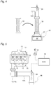
Fig. 3 is a schematic explanatory diagram illustrating a demounting process of a connecting pipe in a maintenance method of the present embodiment. -
Fig. 4 is a schematic explanatory diagram illustrating the mounting process of a maintenance pipe in the maintenance method of the present embodiment. -
Fig. 5 is a schematic explanatory diagram illustrating a fuel injecting process in the maintenance method of the present embodiment. -
Fig. 6 is a schematic explanatory diagram illustrating combustion removal of PM in the maintenance method of the present embodiment. -
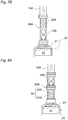
Fig. 7A is a diagram illustrating a first modification of a maintenance pipe, and illustrates the maintenance pipe mounted by disposing a maintenance catalyst in the vicinity of an oxidation catalyst. -
Fig. 7B is a diagram illustrating the first modification of the maintenance pipe, and illustrates the maintenance pipe mounted by disposing the maintenance catalyst in the vicinity of an exhaust pipe injection device. -
Fig. 8A is a diagram illustrating a second modification of a maintenance pipe, and illustrates the maintenance pipe mounted by disposing a maintenance catalyst in the vicinity of an oxidation catalyst. -
Fig. 8B is a diagram illustrating the second modification of the maintenance pipe, and illustrates the maintenance pipe mounted by disposing the maintenance catalyst in the vicinity of an exhaust pipe injection device. -
Fig. 8C is a diagram illustrating the second modification of the maintenance pipe, and illustrates the maintenance pipe mounted by disposing the maintenance catalyst in entirety in a longitudinal direction. -
Fig. 9 is a diagram illustrating a third modification of a maintenance pipe. - Hereinafter, an embodiment of the present invention will be described in detail based on the attached drawings. The same components are given same reference signs, and names and functions thereof are the same. Therefore, detailed description of the same components will not be repeated.
- As illustrated in
Fig. 1 ,injectors 12 for directly injecting high-pressure fuel accumulated in acommon rail 11 into respective cylinders of a diesel engine 10 (hereinafter referred to simply as an engine 10) are provided for the respective cylinders of theengine 10. A fuel injection amount or a fuel injection timing of each of theinjectors 12 is controlled in response to an instruction signal input from an electronic control unit 50 (an ECU 50). - An
intake passage 14 for introducing fresh air is connected to anintake manifold 13 of theengine 10, and anexhaust passage 16 for leading out exhaust gas to the outside is connected to anexhaust manifold 15. Acompressor 17A of avariable capacity supercharger 17 is provided in the middle of theintake passage 14. Aturbine 17B of the variable capacity supercharger 17 and anexhaust purification device 20 are provided for theexhaust passage 16 from an exhaust upstream side in turn. - The variable capacity supercharger 17 and the
exhaust purification device 20 are connected via connectingpipes exhaust passage 16. In the example ofFig. 1 , the variable capacity supercharger 17 and theexhaust purification device 20 are connected via the upstream connectingpipe 16A and the downstream connectingpipe 16B. A number or a shape of the connecting pipes is not limited to this example, and the connecting pipes can be set to an arbitrary number or shape. - The
exhaust purification device 20 is configured to include anoxidation catalyst 22 and a particulate filter 23 (hereinafter, referred to simply as a filter 23) in acase 21 from an exhaust upstream side in turn. An exhaustpipe injection device 24 for injecting unburned fuel (mainly hydrocarbon (HC)) into theexhaust passage 16 in response to the instruction signal input from theECU 50 is provided in the middle of theexhaust passage 16 upstream from theoxidation catalyst 22, and particularly the upstream connectingpipe 16A. - The
oxidation catalyst 22 is an example of a purification member of the present disclosure, and is formed by carrying an oxidation catalyst component on a surface of a ceramic carrier such as a honeycomb structure. When the unburned fuel is supplied by post injection of the exhaustpipe injection device 24 or theinjectors 12, theoxidation catalyst 22 oxidizes the unburned fuel to raise a temperature of the exhaust gas. - The
filter 23 is an example of the purification member of the present disclosure, and is for instance formed such that a plurality of cells sectioned by porous partition walls are disposed in a flowing direction of the exhaust gas, and upstream and downstream sides of the cells are sealed alternately. When PM in the exhaust gas is trapped in pores or surfaces of the partition walls, and when an estimation amount of PM deposition reaches a predetermined amount, thefilter 23 performs so-called filter regeneration by which the PM is burned and removed. The filter regeneration is performed which combusts and removes the PM. The filter-forced regeneration is performed by increasing a concentration of the unburned fuel in the exhaust gas to supply it to theoxidation catalyst 22 by exhaust pipe injection or the post injection, and raising a temperature of the exhaust gas flowing into thefilter 23 to a PM combustion temperature by an oxidation reaction at theoxidation catalyst 22. The exhaustpipe injection device 24 for performing the exhaust pipe injection or theinjector 12 for performing the post injection is an example of the fuel concentration increasing unit of the present disclosure. - The ECU 50 performs various kinds of control on the
engine 10 and the like, and includes a well-known CPU or a ROM, a RAM, an input port, an output port, and the like. To perform the various kinds of control, sensor values of sensors (not shown) are input to theECU 50. In addition, a switch signal from amaintenance switch 51 is input to theECU 50. Themaintenance switch 51 is a switch that is operated when forced regeneration of thefilter 23 is performed. When themaintenance switch 51 is operated, the unburned fuel is injected from the exhaustpipe injection device 24, and the PM deposited on thefilter 23 is burned and removed by the exhaust gas heated by theoxidation catalyst 22. - The
maintenance pipe 30 illustrated inFig. 2 is an example of the maintenance tool of the present disclosure, and is used during maintenance for removing clogging occurring at an exhaust upstream side of theoxidation catalyst 22. Themaintenance pipe 30 includes a flangedsteel pipe 31 that is an example of a tubular member, and amaintenance catalyst 32 that is an example of a heat generating member. - The flanged
steel pipe 31 is formed in the same shape and of the same material as the downstream connectingpipe 16B. As long as the flangedsteel pipe 31 is formed in a shape in which it is mounted to be replaceable with the downstream connectingpipe 16B and is formed of a material having heat resistance over the temperature of the exhaust gas, different shapes and materials may be adopted. - The
maintenance catalyst 32 is housed in theflanged steel pipe 31, generates heat caused by oxidizing the unburned fuel contained in the exhaust gas from the internal combustion engine, and heats the exhaust gas to discharge it to the exhaust downstream side. Themaintenance catalyst 32 includes a ceramic carrier having a honeycomb structure becoming an exhaust flow passage like theoxidation catalyst 22, and carries the oxidation catalyst component on a surface of the carrier. - In the example of
Fig. 2 , theflanged steel pipe 31 has a shape in which ring-like discoid flanges are provided at opposite ends of a pipe main body having a cylindrical straight pipe shape. Themaintenance catalyst 32 is formed in a columnar shape having approximately the same length as the pipemain body 31A. - Next, maintenance work (a maintenance method) of the
oxidation catalyst 22 using theaforementioned maintenance pipe 30 will be described. The maintenance work is performed, for instance, by a dealer or at a maintenance shop of a vehicle on which thediesel engine 10 is mounted. - As illustrated in
Fig. 3 , a demounting process (a first process) of demounting the downstream connectingpipe 16B is performed. The demounting process is performed in a shutdown state of theengine 10, and includes releasing a fastened state between the flanges of the upstream connectingpipe 16A and the downstream connectingpipe 16B, and releasing a fastened state between the flanges of the downstream connectingpipe 16B and the exhaust purification device 20 (the case 21). After the fastened state is released, the downstream connectingpipe 16B is demounted. - After the downstream connecting
pipe 16B is demounted, a mounting process (a second process) of mounting themaintenance pipe 30 in place of the downstream connectingpipe 16B is performed. In the mounting process, the flanges of the upstream connectingpipe 16A and themaintenance pipe 30 are fastened by a plurality of sets of bolts and nuts, and the flanges of the downstream connectingpipe 16B and the exhaust purification device 20 (the case 21) are fastened by a plurality of sets of bolts and nuts. - After the
maintenance pipe 30 is mounted, a fuel concentration increasing process (a third process) of increasing a concentration of the unburned fuel contained in the exhaust gas is performed. As illustrated inFig. 5 , the fuel concentration increasing process is for instance initiated by operating themaintenance switch 51 in an idling state of theengine 10. When an operation signal is input from themaintenance switch 51, theECU 50 outputs an instruction signal to the exhaustpipe injection device 24. When the instruction signal is input, the exhaustpipe injection device 24 continues to inject the unburned fuel for a predetermined time (e.g., several minutes to a dozen minutes). Instead of the injection of the unburned fuel from the exhaustpipe injection device 24 or along with the injection of the unburned fuel, the post injection may be performed by theinjectors 12. - As illustrated in
Fig. 6 , when the concentration of the unburned fuel contained in the exhaust gas increases, themaintenance catalyst 32 having themaintenance pipe 30 oxidizes the unburned fuel to raise a temperature of the exhaust gas. The exhaust gas passing through themaintenance catalyst 32 to reach a high temperature flows into theoxidation catalyst 22. Thereby, PM or tar that is attributed to clogging in theoxidation catalyst 22 is removed by combustion. - After the unburned fuel is injected for a predetermined time, or when another injection termination condition is established, the exhaust pipe injection caused by the exhaust
pipe injection device 24 or the post injection caused by theinjectors 12 is terminated. Afterwards, after themaintenance pipe 30 is cooled to a temperature suitable for replacement work, themaintenance pipe 30 is demounted, and the downstream connectingpipe 16B is connected again. Thereby, the maintenance work is terminated. - In this way, the
maintenance pipe 30 of the present embodiment includes theflanged steel pipe 31 that is mounted to be replaceable with the downstream connectingpipe 16B, and themaintenance catalyst 32 that is housed in theflanged steel pipe 31, generates heat caused by oxidizing the unburned fuel contained in the exhaust gas from theengine 10, and heats the exhaust gas to discharge it to an exhaust downstream side. - In the maintenance work using the
maintenance pipe 30, after themaintenance pipe 30 is mounted instead of the downstream connectingpipe 16B, theengine 10 is started to merely perform the exhaust pipe injection or the post injection, and thereby the clogging of theoxidation catalyst 22 can be eliminated. For this reason, the maintenance work can be made easy. Since no cleaning water is used, waste water treatment does not require time and effort. In this respect, the maintenance work can be made easy. In addition, since a calorific value capable of eliminating the clogging of theoxidation catalyst 22 is sufficient for a calorific value of themaintenance catalyst 32, a required amount of the oxidation catalyst component can be suppressed to one several-th of an amount of the oxidation catalyst component in theoxidation catalyst 22. - The contents of the present disclosure is not limited to the aforementioned embodiment, and the present disclosure may be appropriately modified without departing from the spirit and scope of the invention.
- For example, in a
maintenance pipe 30A of a first modification illustrated inFigs. 7A and7B , a length of amaintenance catalyst 32A is set to be shorter than that of aflanged steel pipe 31A (to approximately the half of the length in the example ofFigs. 7A and7B ), and themaintenance catalyst 32A is disposed close to one side of theflanged steel pipe 31A. In themaintenance pipe 30 of the first modification, as illustrated inFig. 7A , themaintenance pipe 30A is mounted such that themaintenance catalyst 32A is directed to moving toward anoxidation catalyst 22, and thereby high-temperature exhaust gas can be caused to flow into theoxidation catalyst 22. On the other hand, as illustrated inFig. 7B , themaintenance pipe 30A is mounted such that themaintenance catalyst 32A is directed to moving away from theoxidation catalyst 22, and thereby high-temperature exhaust gas that is somewhat lower than in the state ofFig. 7A can be caused to flow into theoxidation catalyst 22. Since an interval between themaintenance catalyst 32A and theoxidation catalyst 22 is widened, a temperature of exhaust gas can be made uniform, uneven heating of a surface of theoxidation catalyst 22 can be suppressed. - In a
maintenance pipe 30B of a second modification illustrated inFigs. 8A ,8B, and 8C , themaintenance pipe 30B is formed of a plurality of short pipes SP (a set of aflanged steel pipe 31B and amaintenance catalyst 32B), and also uses aspacer 33B configured of only the flanged steel pipe. In the examples ofFig. 8A ,8B, and Fig. 8C , lengths of the short pipes SP and thespacer 33B are set to a half of that of a downstream connectingpipe 16B.Fig. 8A is an example in which the short pipes SP are disposed close to anoxidation catalyst 22 and thespacer 33B is disposed close to the exhaustpipe injection device 24. In inverse relation toFig. 8A ,Fig. 8B is an example in which thespacer 33B is disposed close to theoxidation catalyst 22 and the short pipes SP are disposed close to the exhaustpipe injection device 24.Fig. 8C is an example in which two sets of short pipes SP are used. - In this way, the
maintenance pipe 30B is formed by a combination of the plurality of short pipes SP and thespacer 33B, and thereby a calorific value of themaintenance pipe 30B or a flow of exhaust gas thereof can be adjusted. Thereby, a degree of freedom of the adjustment can be increased with respect to a temperature of the exhaust gas and the flow of the exhaust gas. In the second modification, the lengths of the short pipes SP and thespacer 33B are set to, but not limited to, the half of that of the downstream connectingpipe 16B. The lengths may be set to one third or one fourth of that of the downstream connectingpipe 16B. The lengths need not be divided equally. The combination of the short pipes SP and thespacer 33B has only to have the same length as the downstream connectingpipe 16B. - A
maintenance pipe 40 of a third modification illustrated inFig. 9 is used instead of an upstream connectingpipe 16A. In the third modification, since an exhaustpipe injection device 24 is provided for anexhaust adapter 18 connected to an exhaust downstream side of avariable capacity supercharger 17, the maintenance pipe 40 (aflanged steel pipe 41 and a maintenance catalyst 42) can be connected instead of the upstream connectingpipe 16A. That is, if the connecting pipe is mounted on an exhaust downstream side relative to the fuel concentration increasing unit and on an exhaust upstream side relative to theoxidation catalyst 22 in a demountable state, themaintenance pipe 40 can be replaced with amaintenance pipe 30. - In the aforementioned embodiment, the
oxidation catalyst 22 has been described as the purification member of the maintenance target, but another type of purification member may become the maintenance target. For example, the maintenance of the SCR catalyst or the LNT catalyst can also be performed in the same way using theaforementioned maintenance pipe - This application is based upon and claims the benefit of priority from Japanese Patent Application No.
2015-043424, filed March 05, 2015 - The maintenance tool and the maintenance method for the exhaust purification device of the present invention has an effect that the maintenance work of the exhaust purification device can be made easy, and is useful in that working man-hours or costs required for the maintenance work can be reduced to contribute to popularization and promotion of the exhaust purification device.
-
- 10: Diesel engine
- 11: Common rail
- 12: Injector
- 13: Intake manifold
- 14: Intake passage
- 15: Exhaust manifold
- 16: Exhaust passage
- 16A: Upstream connecting pipe
- 16B: Downstream connecting pipe
- 20: Exhaust purification device
- 21: Case
- 22: Oxidation catalyst
- 23: Particulate filter
- 24: Exhaust pipe injection device
- 30, 30A, 30B: Maintenance pipe
- 31, 31A, 31B: Flanged steel pipe
- 32, 32A, 32B: Maintenance catalyst
- 40: Maintenance pipe
- 41: Flanged steel pipe
- 42: Maintenance catalyst
- 50: ECU
- 51: Maintenance switch
- SP: Short pipe
Claims (3)
- A maintenance tool used during maintenance of an exhaust purification device which includes a purification member that purifies exhaust gas from an internal combustion engine, a connecting pipe that guides the exhaust gas from the internal combustion engine to the purification member and is mounted in a demountable way, and a fuel concentration increasing unit that increases a concentration of unburned fuel contained in the exhaust gas, the maintenance tool comprising:a tubular member mounted to be replaceable with the connecting pipe; anda heat generating member housed in the tubular member, configured to generate heat caused by oxidizing the unburned fuel contained in the exhaust gas from the internal combustion engine, and configured to heat the exhaust gas to discharge the exhaust gas to an exhaust downstream side.
- The maintenance tool according to claim 1,
wherein the heat generating member is formed by carrying a catalyst component on a surface of a heat-resistant carrier in which an exhaust passage is formed. - A maintenance method for an exhaust purification device which includes a purification member that purifies exhaust gas from an internal combustion engine, a connecting pipe that guides the exhaust gas from the internal combustion engine to the purification member and is mounted in a demountable way, and a fuel concentration increasing unit that increases a concentration of unburned fuel contained in the exhaust gas, the maintenance method comprising:a first process of demounting the connecting pipe;a second process of mounting a maintenance tool, which includes a tubular member mounted to be replaceable with the connecting pipe, and a heat generating member housed in the tubular member, configured to generate heat caused by oxidizing the unburned fuel contained in the exhaust gas from the internal combustion engine, and configured to heat the exhaust gas to discharge the exhaust gas to an exhaust downstream side, instead of the connecting pipe; anda third process of increasing a concentration of the unburned fuel contained in the exhaust gas using the fuel concentration increasing unit.
Applications Claiming Priority (2)
| Application Number | Priority Date | Filing Date | Title |
|---|---|---|---|
| JP2015043424A JP6414488B2 (en) | 2015-03-05 | 2015-03-05 | Exhaust purification device maintenance tool and maintenance method |
| PCT/JP2016/056077 WO2016140193A1 (en) | 2015-03-05 | 2016-02-29 | Maintenance tool and maintenance method for exhaust purification device |
Publications (3)
| Publication Number | Publication Date |
|---|---|
| EP3267001A1 true EP3267001A1 (en) | 2018-01-10 |
| EP3267001A4 EP3267001A4 (en) | 2018-08-01 |
| EP3267001B1 EP3267001B1 (en) | 2020-04-08 |
Family
ID=56844529
Family Applications (1)
| Application Number | Title | Priority Date | Filing Date |
|---|---|---|---|
| EP16758886.2A Active EP3267001B1 (en) | 2015-03-05 | 2016-02-29 | Maintenance tool and maintenance method for exhaust purification device |
Country Status (5)
| Country | Link |
|---|---|
| US (1) | US10920633B2 (en) |
| EP (1) | EP3267001B1 (en) |
| JP (1) | JP6414488B2 (en) |
| CN (1) | CN107407176B (en) |
| WO (1) | WO2016140193A1 (en) |
Family Cites Families (21)
| Publication number | Priority date | Publication date | Assignee | Title |
|---|---|---|---|---|
| US1422211A (en) * | 1919-05-31 | 1922-07-11 | Arthur B Lamb | Method and apparatus for treating gases and gaseous substances |
| US3247665A (en) * | 1964-04-02 | 1966-04-26 | Texaco Inc | Catalytic muffler construction for exhaust emission control in an internal combustion engine system |
| US3884037A (en) * | 1969-02-17 | 1975-05-20 | Texaco Inc | Internal combustion engine system for exhaust emissions control utilizing an acoustic catalytic muffler |
| US4485621A (en) * | 1983-01-07 | 1984-12-04 | Cummins Engine Company, Inc. | System and method for reducing particulate emissions from internal combustion engines |
| US5169604A (en) * | 1991-10-30 | 1992-12-08 | Johnson Matthey, Inc. | Catalytic converter with replaceable carrier assembly |
| US5849251A (en) * | 1995-07-17 | 1998-12-15 | Timko; Mark | Catalytic converter for a tailpipe including apparatus for relieving back pressure |
| US6584768B1 (en) * | 2000-11-16 | 2003-07-01 | The Majestic Companies, Ltd. | Vehicle exhaust filtration system and method |
| JP2003120258A (en) * | 2001-10-19 | 2003-04-23 | Shigeru Kuroda | Exhaust gas particulate removing device for diesel engine |
| JP4045935B2 (en) * | 2002-11-25 | 2008-02-13 | 三菱ふそうトラック・バス株式会社 | Exhaust gas purification device for internal combustion engine |
| DE10300298A1 (en) * | 2003-01-02 | 2004-07-15 | Daimlerchrysler Ag | Exhaust gas aftertreatment device and method |
| DE102004062897A1 (en) | 2004-12-21 | 2006-07-06 | Ath Technologie Holding Gmbh | Exhaust gas treatment system for internal combustion engine has at least one time switched device to collect carbon-oxygen compounds before converter |
| JP2006204969A (en) | 2005-01-25 | 2006-08-10 | Hino Motors Ltd | Exhaust purification device |
| US7517380B2 (en) * | 2006-01-26 | 2009-04-14 | Fleetguard, Inc. | Serviceable aligned exhaust aftertreatment assembly |
| CA2595155C (en) | 2007-07-27 | 2013-10-08 | Silex Innovations Inc. | Securing catalyst element in catalytic converter with bolted bar |
| JP5107822B2 (en) * | 2008-08-11 | 2012-12-26 | 日立建機株式会社 | Exhaust gas purification device |
| JP5133422B2 (en) * | 2008-09-08 | 2013-01-30 | 日立建機株式会社 | Exhaust gas treatment equipment |
| JP5720119B2 (en) * | 2010-05-28 | 2015-05-20 | いすゞ自動車株式会社 | Exhaust gas purification device for internal combustion engine |
| CN103561847A (en) | 2011-04-18 | 2014-02-05 | 雷恩宇宙有限责任公司 | Method and apparatus for removal of carbon dioxide from automobile, household and industrial exhaust gases |
| US9057316B2 (en) * | 2012-12-03 | 2015-06-16 | Tenneco Automotive Operating Company Inc. | Exhaust component mounting structure |
| JP6560587B2 (en) * | 2015-10-06 | 2019-08-14 | 日立建機株式会社 | Construction machinery |
| US10280822B2 (en) * | 2017-07-11 | 2019-05-07 | Toyota Jidosha Kabushiki Kaisha | Exhaust gas purifying apparatus |
-
2015
- 2015-03-05 JP JP2015043424A patent/JP6414488B2/en not_active Expired - Fee Related
-
2016
- 2016-02-29 CN CN201680013593.2A patent/CN107407176B/en active Active
- 2016-02-29 WO PCT/JP2016/056077 patent/WO2016140193A1/en not_active Ceased
- 2016-02-29 EP EP16758886.2A patent/EP3267001B1/en active Active
- 2016-02-29 US US15/555,430 patent/US10920633B2/en active Active
Also Published As
| Publication number | Publication date |
|---|---|
| EP3267001B1 (en) | 2020-04-08 |
| US20180038253A1 (en) | 2018-02-08 |
| CN107407176A (en) | 2017-11-28 |
| JP2016160910A (en) | 2016-09-05 |
| EP3267001A4 (en) | 2018-08-01 |
| JP6414488B2 (en) | 2018-10-31 |
| CN107407176B (en) | 2019-09-13 |
| WO2016140193A1 (en) | 2016-09-09 |
| US10920633B2 (en) | 2021-02-16 |
Similar Documents
| Publication | Publication Date | Title |
|---|---|---|
| CN103388513B (en) | Vehicle and the method controlling to produce the operating of the after-treatment system in the vehicle of aerofluxus | |
| US20140053539A1 (en) | Exhaust component mounting system | |
| DE69916312D1 (en) | METHOD AND DEVICE FOR TREATING COMBUSTION EXHAUST GASES | |
| CN207363741U (en) | Exhaust aftertreatment systems for diesel engines | |
| RU2009132607A (en) | METHOD OF REGENERATION OF SOOT FILTERS IN THE SYSTEM OF EXHAUST OF EXHAUST GASES FOR THE EMPLOYED ENGINE MIXTURES OF THE INTERNAL COMBUSTION ENGINE AND DESIGNED FOR THIS EXHAUST SYSTEM | |
| WO2008035623A1 (en) | Engine exhaust gas purification apparatus | |
| JP2010019239A (en) | Exhaust emission control device | |
| US20150023844A1 (en) | Siloxane filter in an exhaust aftertreatment system | |
| RU2566614C1 (en) | Exhaust gas cleaning apparatus for internal combustion engine | |
| US8276371B2 (en) | Exhaust system having exhaust system segment with improved catalyst distribution and method | |
| US10920633B2 (en) | Maintenance tool and maintenance method for exhaust purification device | |
| US8584445B2 (en) | Method and system for controlling an electrically heated particulate filter | |
| US20140137382A1 (en) | Method of retrofitting an aftreatment system | |
| KR101628098B1 (en) | Exhaust gas purification system for vehicle | |
| JP6398402B2 (en) | Exhaust purification system | |
| JP6398401B2 (en) | Exhaust purification system | |
| JP7354976B2 (en) | Internal combustion engine exhaust purification system | |
| US10415448B2 (en) | Exhaust gas cleaning system for internal combustion engine and exhaust gas cleaning method for internal combustion engine | |
| US12253014B1 (en) | Reduced internal combustion engine particulate matter emissions | |
| JP2005291062A (en) | Filter device, and exhaust emission control device provided with the same | |
| US11446599B2 (en) | Particulate filter and manufacturing method for same | |
| JP2017145755A (en) | Exhaust purification system | |
| JP6790787B2 (en) | Exhaust gas purification device for internal combustion engine | |
| CN112424459A (en) | Exhaust structure of vehicle-mounted engine | |
| JP2007187077A (en) | Exhaust gas after-treatment device |
Legal Events
| Date | Code | Title | Description |
|---|---|---|---|
| STAA | Information on the status of an ep patent application or granted ep patent |
Free format text: STATUS: THE INTERNATIONAL PUBLICATION HAS BEEN MADE |
|
| PUAI | Public reference made under article 153(3) epc to a published international application that has entered the european phase |
Free format text: ORIGINAL CODE: 0009012 |
|
| STAA | Information on the status of an ep patent application or granted ep patent |
Free format text: STATUS: REQUEST FOR EXAMINATION WAS MADE |
|
| 17P | Request for examination filed |
Effective date: 20171005 |
|
| AK | Designated contracting states |
Kind code of ref document: A1 Designated state(s): AL AT BE BG CH CY CZ DE DK EE ES FI FR GB GR HR HU IE IS IT LI LT LU LV MC MK MT NL NO PL PT RO RS SE SI SK SM TR |
|
| AX | Request for extension of the european patent |
Extension state: BA ME |
|
| DAV | Request for validation of the european patent (deleted) | ||
| DAX | Request for extension of the european patent (deleted) | ||
| A4 | Supplementary search report drawn up and despatched |
Effective date: 20180704 |
|
| RIC1 | Information provided on ipc code assigned before grant |
Ipc: F01N 9/00 20060101ALI20180628BHEP Ipc: F01N 3/36 20060101ALI20180628BHEP Ipc: F01N 3/20 20060101AFI20180628BHEP Ipc: F01N 3/025 20060101ALI20180628BHEP |
|
| STAA | Information on the status of an ep patent application or granted ep patent |
Free format text: STATUS: EXAMINATION IS IN PROGRESS |
|
| 17Q | First examination report despatched |
Effective date: 20190214 |
|
| GRAP | Despatch of communication of intention to grant a patent |
Free format text: ORIGINAL CODE: EPIDOSNIGR1 |
|
| STAA | Information on the status of an ep patent application or granted ep patent |
Free format text: STATUS: GRANT OF PATENT IS INTENDED |
|
| INTG | Intention to grant announced |
Effective date: 20191022 |
|
| GRAS | Grant fee paid |
Free format text: ORIGINAL CODE: EPIDOSNIGR3 |
|
| GRAA | (expected) grant |
Free format text: ORIGINAL CODE: 0009210 |
|
| STAA | Information on the status of an ep patent application or granted ep patent |
Free format text: STATUS: THE PATENT HAS BEEN GRANTED |
|
| AK | Designated contracting states |
Kind code of ref document: B1 Designated state(s): AL AT BE BG CH CY CZ DE DK EE ES FI FR GB GR HR HU IE IS IT LI LT LU LV MC MK MT NL NO PL PT RO RS SE SI SK SM TR |
|
| REG | Reference to a national code |
Ref country code: AT Ref legal event code: REF Ref document number: 1254676 Country of ref document: AT Kind code of ref document: T Effective date: 20200415 Ref country code: CH Ref legal event code: EP |
|
| REG | Reference to a national code |
Ref country code: DE Ref legal event code: R096 Ref document number: 602016033645 Country of ref document: DE |
|
| REG | Reference to a national code |
Ref country code: IE Ref legal event code: FG4D |
|
| REG | Reference to a national code |
Ref country code: NL Ref legal event code: MP Effective date: 20200408 |
|
| REG | Reference to a national code |
Ref country code: LT Ref legal event code: MG4D |
|
| PG25 | Lapsed in a contracting state [announced via postgrant information from national office to epo] |
Ref country code: NO Free format text: LAPSE BECAUSE OF FAILURE TO SUBMIT A TRANSLATION OF THE DESCRIPTION OR TO PAY THE FEE WITHIN THE PRESCRIBED TIME-LIMIT Effective date: 20200708 Ref country code: GR Free format text: LAPSE BECAUSE OF FAILURE TO SUBMIT A TRANSLATION OF THE DESCRIPTION OR TO PAY THE FEE WITHIN THE PRESCRIBED TIME-LIMIT Effective date: 20200709 Ref country code: PT Free format text: LAPSE BECAUSE OF FAILURE TO SUBMIT A TRANSLATION OF THE DESCRIPTION OR TO PAY THE FEE WITHIN THE PRESCRIBED TIME-LIMIT Effective date: 20200817 Ref country code: FI Free format text: LAPSE BECAUSE OF FAILURE TO SUBMIT A TRANSLATION OF THE DESCRIPTION OR TO PAY THE FEE WITHIN THE PRESCRIBED TIME-LIMIT Effective date: 20200408 Ref country code: IS Free format text: LAPSE BECAUSE OF FAILURE TO SUBMIT A TRANSLATION OF THE DESCRIPTION OR TO PAY THE FEE WITHIN THE PRESCRIBED TIME-LIMIT Effective date: 20200808 Ref country code: LT Free format text: LAPSE BECAUSE OF FAILURE TO SUBMIT A TRANSLATION OF THE DESCRIPTION OR TO PAY THE FEE WITHIN THE PRESCRIBED TIME-LIMIT Effective date: 20200408 Ref country code: NL Free format text: LAPSE BECAUSE OF FAILURE TO SUBMIT A TRANSLATION OF THE DESCRIPTION OR TO PAY THE FEE WITHIN THE PRESCRIBED TIME-LIMIT Effective date: 20200408 Ref country code: SE Free format text: LAPSE BECAUSE OF FAILURE TO SUBMIT A TRANSLATION OF THE DESCRIPTION OR TO PAY THE FEE WITHIN THE PRESCRIBED TIME-LIMIT Effective date: 20200408 |
|
| REG | Reference to a national code |
Ref country code: AT Ref legal event code: MK05 Ref document number: 1254676 Country of ref document: AT Kind code of ref document: T Effective date: 20200408 |
|
| PG25 | Lapsed in a contracting state [announced via postgrant information from national office to epo] |
Ref country code: LV Free format text: LAPSE BECAUSE OF FAILURE TO SUBMIT A TRANSLATION OF THE DESCRIPTION OR TO PAY THE FEE WITHIN THE PRESCRIBED TIME-LIMIT Effective date: 20200408 Ref country code: HR Free format text: LAPSE BECAUSE OF FAILURE TO SUBMIT A TRANSLATION OF THE DESCRIPTION OR TO PAY THE FEE WITHIN THE PRESCRIBED TIME-LIMIT Effective date: 20200408 Ref country code: BG Free format text: LAPSE BECAUSE OF FAILURE TO SUBMIT A TRANSLATION OF THE DESCRIPTION OR TO PAY THE FEE WITHIN THE PRESCRIBED TIME-LIMIT Effective date: 20200708 Ref country code: RS Free format text: LAPSE BECAUSE OF FAILURE TO SUBMIT A TRANSLATION OF THE DESCRIPTION OR TO PAY THE FEE WITHIN THE PRESCRIBED TIME-LIMIT Effective date: 20200408 |
|
| PG25 | Lapsed in a contracting state [announced via postgrant information from national office to epo] |
Ref country code: AL Free format text: LAPSE BECAUSE OF FAILURE TO SUBMIT A TRANSLATION OF THE DESCRIPTION OR TO PAY THE FEE WITHIN THE PRESCRIBED TIME-LIMIT Effective date: 20200408 |
|
| REG | Reference to a national code |
Ref country code: DE Ref legal event code: R097 Ref document number: 602016033645 Country of ref document: DE |
|
| PG25 | Lapsed in a contracting state [announced via postgrant information from national office to epo] |
Ref country code: DK Free format text: LAPSE BECAUSE OF FAILURE TO SUBMIT A TRANSLATION OF THE DESCRIPTION OR TO PAY THE FEE WITHIN THE PRESCRIBED TIME-LIMIT Effective date: 20200408 Ref country code: AT Free format text: LAPSE BECAUSE OF FAILURE TO SUBMIT A TRANSLATION OF THE DESCRIPTION OR TO PAY THE FEE WITHIN THE PRESCRIBED TIME-LIMIT Effective date: 20200408 Ref country code: ES Free format text: LAPSE BECAUSE OF FAILURE TO SUBMIT A TRANSLATION OF THE DESCRIPTION OR TO PAY THE FEE WITHIN THE PRESCRIBED TIME-LIMIT Effective date: 20200408 Ref country code: EE Free format text: LAPSE BECAUSE OF FAILURE TO SUBMIT A TRANSLATION OF THE DESCRIPTION OR TO PAY THE FEE WITHIN THE PRESCRIBED TIME-LIMIT Effective date: 20200408 Ref country code: SM Free format text: LAPSE BECAUSE OF FAILURE TO SUBMIT A TRANSLATION OF THE DESCRIPTION OR TO PAY THE FEE WITHIN THE PRESCRIBED TIME-LIMIT Effective date: 20200408 Ref country code: CZ Free format text: LAPSE BECAUSE OF FAILURE TO SUBMIT A TRANSLATION OF THE DESCRIPTION OR TO PAY THE FEE WITHIN THE PRESCRIBED TIME-LIMIT Effective date: 20200408 Ref country code: IT Free format text: LAPSE BECAUSE OF FAILURE TO SUBMIT A TRANSLATION OF THE DESCRIPTION OR TO PAY THE FEE WITHIN THE PRESCRIBED TIME-LIMIT Effective date: 20200408 Ref country code: RO Free format text: LAPSE BECAUSE OF FAILURE TO SUBMIT A TRANSLATION OF THE DESCRIPTION OR TO PAY THE FEE WITHIN THE PRESCRIBED TIME-LIMIT Effective date: 20200408 |
|
| PLBE | No opposition filed within time limit |
Free format text: ORIGINAL CODE: 0009261 |
|
| STAA | Information on the status of an ep patent application or granted ep patent |
Free format text: STATUS: NO OPPOSITION FILED WITHIN TIME LIMIT |
|
| PG25 | Lapsed in a contracting state [announced via postgrant information from national office to epo] |
Ref country code: PL Free format text: LAPSE BECAUSE OF FAILURE TO SUBMIT A TRANSLATION OF THE DESCRIPTION OR TO PAY THE FEE WITHIN THE PRESCRIBED TIME-LIMIT Effective date: 20200408 Ref country code: SK Free format text: LAPSE BECAUSE OF FAILURE TO SUBMIT A TRANSLATION OF THE DESCRIPTION OR TO PAY THE FEE WITHIN THE PRESCRIBED TIME-LIMIT Effective date: 20200408 |
|
| 26N | No opposition filed |
Effective date: 20210112 |
|
| PG25 | Lapsed in a contracting state [announced via postgrant information from national office to epo] |
Ref country code: SI Free format text: LAPSE BECAUSE OF FAILURE TO SUBMIT A TRANSLATION OF THE DESCRIPTION OR TO PAY THE FEE WITHIN THE PRESCRIBED TIME-LIMIT Effective date: 20200408 |
|
| PG25 | Lapsed in a contracting state [announced via postgrant information from national office to epo] |
Ref country code: MC Free format text: LAPSE BECAUSE OF FAILURE TO SUBMIT A TRANSLATION OF THE DESCRIPTION OR TO PAY THE FEE WITHIN THE PRESCRIBED TIME-LIMIT Effective date: 20200408 |
|
| REG | Reference to a national code |
Ref country code: BE Ref legal event code: MM Effective date: 20210228 |
|
| PG25 | Lapsed in a contracting state [announced via postgrant information from national office to epo] |
Ref country code: CH Free format text: LAPSE BECAUSE OF NON-PAYMENT OF DUE FEES Effective date: 20210228 Ref country code: LU Free format text: LAPSE BECAUSE OF NON-PAYMENT OF DUE FEES Effective date: 20210228 Ref country code: LI Free format text: LAPSE BECAUSE OF NON-PAYMENT OF DUE FEES Effective date: 20210228 |
|
| PG25 | Lapsed in a contracting state [announced via postgrant information from national office to epo] |
Ref country code: IE Free format text: LAPSE BECAUSE OF NON-PAYMENT OF DUE FEES Effective date: 20210228 |
|
| PG25 | Lapsed in a contracting state [announced via postgrant information from national office to epo] |
Ref country code: BE Free format text: LAPSE BECAUSE OF NON-PAYMENT OF DUE FEES Effective date: 20210228 |
|
| PGFP | Annual fee paid to national office [announced via postgrant information from national office to epo] |
Ref country code: FR Payment date: 20230110 Year of fee payment: 8 |
|
| PGFP | Annual fee paid to national office [announced via postgrant information from national office to epo] |
Ref country code: GB Payment date: 20230105 Year of fee payment: 8 |
|
| PG25 | Lapsed in a contracting state [announced via postgrant information from national office to epo] |
Ref country code: CY Free format text: LAPSE BECAUSE OF FAILURE TO SUBMIT A TRANSLATION OF THE DESCRIPTION OR TO PAY THE FEE WITHIN THE PRESCRIBED TIME-LIMIT Effective date: 20200408 |
|
| PG25 | Lapsed in a contracting state [announced via postgrant information from national office to epo] |
Ref country code: HU Free format text: LAPSE BECAUSE OF FAILURE TO SUBMIT A TRANSLATION OF THE DESCRIPTION OR TO PAY THE FEE WITHIN THE PRESCRIBED TIME-LIMIT; INVALID AB INITIO Effective date: 20160229 |
|
| PG25 | Lapsed in a contracting state [announced via postgrant information from national office to epo] |
Ref country code: MK Free format text: LAPSE BECAUSE OF FAILURE TO SUBMIT A TRANSLATION OF THE DESCRIPTION OR TO PAY THE FEE WITHIN THE PRESCRIBED TIME-LIMIT Effective date: 20200408 |
|
| REG | Reference to a national code |
Ref country code: DE Ref legal event code: R082 Ref document number: 602016033645 Country of ref document: DE Representative=s name: MEISSNER BOLTE PATENTANWAELTE RECHTSANWAELTE P, DE |
|
| PG25 | Lapsed in a contracting state [announced via postgrant information from national office to epo] |
Ref country code: MT Free format text: LAPSE BECAUSE OF FAILURE TO SUBMIT A TRANSLATION OF THE DESCRIPTION OR TO PAY THE FEE WITHIN THE PRESCRIBED TIME-LIMIT Effective date: 20200408 |
|
| GBPC | Gb: european patent ceased through non-payment of renewal fee |
Effective date: 20240229 |
|
| PG25 | Lapsed in a contracting state [announced via postgrant information from national office to epo] |
Ref country code: GB Free format text: LAPSE BECAUSE OF NON-PAYMENT OF DUE FEES Effective date: 20240229 |
|
| PG25 | Lapsed in a contracting state [announced via postgrant information from national office to epo] |
Ref country code: FR Free format text: LAPSE BECAUSE OF NON-PAYMENT OF DUE FEES Effective date: 20240229 |
|
| PG25 | Lapsed in a contracting state [announced via postgrant information from national office to epo] |
Ref country code: GB Free format text: LAPSE BECAUSE OF NON-PAYMENT OF DUE FEES Effective date: 20240229 Ref country code: FR Free format text: LAPSE BECAUSE OF NON-PAYMENT OF DUE FEES Effective date: 20240229 |
|
| PG25 | Lapsed in a contracting state [announced via postgrant information from national office to epo] |
Ref country code: TR Free format text: LAPSE BECAUSE OF FAILURE TO SUBMIT A TRANSLATION OF THE DESCRIPTION OR TO PAY THE FEE WITHIN THE PRESCRIBED TIME-LIMIT Effective date: 20200408 |
|
| PGFP | Annual fee paid to national office [announced via postgrant information from national office to epo] |
Ref country code: DE Payment date: 20260121 Year of fee payment: 11 |