EP3266703B1 - Lenkbarer ballon, der mit einem kompakten solargenerator mit lokaler konzentration ausgestattet ist, der reihen von zweiseitigen solarzellen verwendet - Google Patents
Lenkbarer ballon, der mit einem kompakten solargenerator mit lokaler konzentration ausgestattet ist, der reihen von zweiseitigen solarzellen verwendet Download PDFInfo
- Publication number
- EP3266703B1 EP3266703B1 EP17169421.9A EP17169421A EP3266703B1 EP 3266703 B1 EP3266703 B1 EP 3266703B1 EP 17169421 A EP17169421 A EP 17169421A EP 3266703 B1 EP3266703 B1 EP 3266703B1
- Authority
- EP
- European Patent Office
- Prior art keywords
- solar
- compact
- local
- longitudinal
- cells
- Prior art date
- Legal status (The legal status is an assumption and is not a legal conclusion. Google has not performed a legal analysis and makes no representation as to the accuracy of the status listed.)
- Active
Links
Images





Classifications
-
- H—ELECTRICITY
- H02—GENERATION; CONVERSION OR DISTRIBUTION OF ELECTRIC POWER
- H02S—GENERATION OF ELECTRIC POWER BY CONVERSION OF INFRARED RADIATION, VISIBLE LIGHT OR ULTRAVIOLET LIGHT, e.g. USING PHOTOVOLTAIC [PV] MODULES
- H02S40/00—Components or accessories in combination with PV modules, not provided for in groups H02S10/00 - H02S30/00
- H02S40/20—Optical components
- H02S40/22—Light-reflecting or light-concentrating means
-
- B—PERFORMING OPERATIONS; TRANSPORTING
- B64—AIRCRAFT; AVIATION; COSMONAUTICS
- B64B—LIGHTER-THAN AIR AIRCRAFT
- B64B1/00—Lighter-than-air aircraft
- B64B1/06—Rigid airships; Semi-rigid airships
-
- B—PERFORMING OPERATIONS; TRANSPORTING
- B64—AIRCRAFT; AVIATION; COSMONAUTICS
- B64B—LIGHTER-THAN AIR AIRCRAFT
- B64B1/00—Lighter-than-air aircraft
- B64B1/06—Rigid airships; Semi-rigid airships
- B64B1/14—Outer covering
-
- B—PERFORMING OPERATIONS; TRANSPORTING
- B64—AIRCRAFT; AVIATION; COSMONAUTICS
- B64B—LIGHTER-THAN AIR AIRCRAFT
- B64B1/00—Lighter-than-air aircraft
- B64B1/40—Balloons
- B64B1/44—Balloons adapted to maintain predetermined altitude
-
- H—ELECTRICITY
- H02—GENERATION; CONVERSION OR DISTRIBUTION OF ELECTRIC POWER
- H02S—GENERATION OF ELECTRIC POWER BY CONVERSION OF INFRARED RADIATION, VISIBLE LIGHT OR ULTRAVIOLET LIGHT, e.g. USING PHOTOVOLTAIC [PV] MODULES
- H02S10/00—PV power plants; Combinations of PV energy systems with other systems for the generation of electric power
- H02S10/40—Mobile PV generator systems
-
- H—ELECTRICITY
- H02—GENERATION; CONVERSION OR DISTRIBUTION OF ELECTRIC POWER
- H02S—GENERATION OF ELECTRIC POWER BY CONVERSION OF INFRARED RADIATION, VISIBLE LIGHT OR ULTRAVIOLET LIGHT, e.g. USING PHOTOVOLTAIC [PV] MODULES
- H02S99/00—Subject matter not provided for in other groups of this subclass
-
- H—ELECTRICITY
- H10—SEMICONDUCTOR DEVICES; ELECTRIC SOLID-STATE DEVICES NOT OTHERWISE PROVIDED FOR
- H10F—INORGANIC SEMICONDUCTOR DEVICES SENSITIVE TO INFRARED RADIATION, LIGHT, ELECTROMAGNETIC RADIATION OF SHORTER WAVELENGTH OR CORPUSCULAR RADIATION
- H10F10/00—Individual photovoltaic cells, e.g. solar cells
- H10F10/10—Individual photovoltaic cells, e.g. solar cells having potential barriers
- H10F10/14—Photovoltaic cells having only PN homojunction potential barriers
- H10F10/148—Double-emitter photovoltaic cells, e.g. bifacial photovoltaic cells
-
- H—ELECTRICITY
- H10—SEMICONDUCTOR DEVICES; ELECTRIC SOLID-STATE DEVICES NOT OTHERWISE PROVIDED FOR
- H10F—INORGANIC SEMICONDUCTOR DEVICES SENSITIVE TO INFRARED RADIATION, LIGHT, ELECTROMAGNETIC RADIATION OF SHORTER WAVELENGTH OR CORPUSCULAR RADIATION
- H10F77/00—Constructional details of devices covered by this subclass
- H10F77/40—Optical elements or arrangements
- H10F77/42—Optical elements or arrangements directly associated or integrated with photovoltaic cells, e.g. light-reflecting means or light-concentrating means
- H10F77/48—Back surface reflectors [BSR]
-
- Y—GENERAL TAGGING OF NEW TECHNOLOGICAL DEVELOPMENTS; GENERAL TAGGING OF CROSS-SECTIONAL TECHNOLOGIES SPANNING OVER SEVERAL SECTIONS OF THE IPC; TECHNICAL SUBJECTS COVERED BY FORMER USPC CROSS-REFERENCE ART COLLECTIONS [XRACs] AND DIGESTS
- Y02—TECHNOLOGIES OR APPLICATIONS FOR MITIGATION OR ADAPTATION AGAINST CLIMATE CHANGE
- Y02E—REDUCTION OF GREENHOUSE GAS [GHG] EMISSIONS, RELATED TO ENERGY GENERATION, TRANSMISSION OR DISTRIBUTION
- Y02E10/00—Energy generation through renewable energy sources
- Y02E10/50—Photovoltaic [PV] energy
- Y02E10/52—PV systems with concentrators
-
- Y—GENERAL TAGGING OF NEW TECHNOLOGICAL DEVELOPMENTS; GENERAL TAGGING OF CROSS-SECTIONAL TECHNOLOGIES SPANNING OVER SEVERAL SECTIONS OF THE IPC; TECHNICAL SUBJECTS COVERED BY FORMER USPC CROSS-REFERENCE ART COLLECTIONS [XRACs] AND DIGESTS
- Y02—TECHNOLOGIES OR APPLICATIONS FOR MITIGATION OR ADAPTATION AGAINST CLIMATE CHANGE
- Y02E—REDUCTION OF GREENHOUSE GAS [GHG] EMISSIONS, RELATED TO ENERGY GENERATION, TRANSMISSION OR DISTRIBUTION
- Y02E10/00—Energy generation through renewable energy sources
- Y02E10/50—Photovoltaic [PV] energy
- Y02E10/547—Monocrystalline silicon PV cells
Definitions
- the present invention relates to an airship, equipped with a compact solar generator using bifacial solar cell lines.
- Such an airship is known from FR 3 015 149 A1 , which is considered the closest prior art and describes the features of the preamble of claim 1.
- the field of the invention relates to solar generators with solar radiation concentration, intended after installation, to supply electrical energy to an airship and to make said balloon autonomous from an energy point of view with respect to its propulsion and the power of its embedded systems on board.
- a stratospheric balloon 2 of this type has a large size and uses a high power electric propulsion system 4, that is to say for example a propeller system driven by one or more engines
- the balloon has an elongated shape in a longitudinal direction and has an outer envelope 8 contained in a cylindrical jig about 100 meters long and 30 meters in diameter.
- a size of the balloon 2 corresponds to a need for electrical energy equal to about a hundred kilowatts.
- the solar panel 6 of the solar generator 16 is disposed at the top 18 of the balloon 2 while the radiation concentrator 14 is disposed and installed inside the outer envelope 8, significantly away from the vertex 18 of the 8.
- the radiation concentrator 14 is disposed longitudinally close to a longitudinal central axis 20 of the balloon as shown in FIG. Figure 1 or at a level below the longitudinal axis away from the top of the outer shell 8.
- a balloon 52 with a solar generator 54 of concentration comprises and uses cells bifacial solar cells 56, disposed at the top 58 of its outer casing 60.
- the solar generator 54 comprises a solar radiation concentrator 62, disposed inside the outer casing 60 and flexibly installed on a first lower zone 64 of the outer casing 60 facing the top 58 of the same outer casing 60.
- the outer casing 60 comprises towards the top 58, on both sides of the bifacial solar cells 56 arranged in a strip 66, a second transparent zone 70 for let the solar rays 72 pass to the radiation concentrator 62.
- the radiation concentrator installed in and fixed to the outer casing of the balloon, is difficult to achieve, on the one hand in terms of meeting the geometrical requirements of the placement accuracy of said concentrator vis-à-vis the solar cells in a flexible outer envelope subjected to deformations, and secondly in terms of integration into an outer envelope also sealed.
- this configuration of a radiation concentrator implanted inside the airship outer envelope couples the design constraints of the outer envelope with those of the solar generator design, which makes it difficult to obtain a simple solution to implement and makes the system difficult to test.
- the current solar generator system requires a transparent outer envelope, at least over an area of its upper part, which decreases the efficiency of the solar generator due to the absorption of radiation.
- solar energy to the penetrations of the walls of the envelope and limits the cooling by infrared radiation from the back of solar cells, a transparent material in the visible that is not in the infrared.
- the material of the envelope to be both transparent and very strong mechanically over a long life, that is to say here over at least five years, difficulties of technological achievement remain to overcome and come added.
- allowing the solar radiation to enter the balloon causes the balloon to heat up internally, which increases the internal pressure of the balloon and requires oversizing of the mechanical strength of the envelope.
- the present invention aims to overcome the aforementioned drawbacks.
- the technical problem is to provide a lighter solar generator, simple to implement, more efficient in terms of power supply efficiency delivered per unit area of solar cells, with a minimum of mechanical and thermal interaction with the balloon envelope.
- the underlying concept of the invention consists in replacing the solar generator according to the state of the art, the global solar concentrator is integrated inside the outer envelope of the airship by a compact solar generator, concentration local radiation, thin relative to the diameter of the balloon, wherein a set of local concentrators is disposed outside and at the top of the outer shell of the balloon.
- the local concentrators are located below and as close as the bifacial cells, marry and follow the surface of the balloon while ensuring efficient two-sided concentration of solar radiation to the solar cells to maximize the energy performance of the global solar panel.
- this compact local concentration solar generator solution installed entirely outside the balloon, overcomes the aforementioned technical problems presented by current solar generator systems, without disturbing the aerodynamics and the thermal of the balloon. because of the small thickness of the solar generator relative to the diameter of the balloon and because of the absence of direct contact of the hot parts of the solar generator, that is to say the solar cells, with the balloon envelope.
- an airship 102 is equipped with a compact solar generator 104 at local concentration to supply electrical energy to said balloon 102 in flight from solar radiation.
- the dirigible balloon 102 comprises an outer casing 108, a carrier gas 110 contained in the outer casing 108, and the compact solar generator 104 with a local concentration of solar radiation.
- the outer casing 108 has a closed outer surface 114 of elongate shape along a predetermined longitudinal central axis 116.
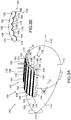
- the compact solar generator comprises a first set 122 of at least one line 124, 126, 128, 130, 132 of bifacial photovoltaic solar cells 134, and a solar radiation concentrator 136 for converging solar rays towards rear faces of the bifacial solar cells 134 of the first set 122.
- the first set 122 of solar cell lines 134, 126, 128, 130, 132 is disposed above and at a predetermined height h of a compact vertex portion 138 of apex 140 of outer surface 114, in which each line 124 , 126, 128, 130, 132 bifacial solar cells 134 is configured to follow respectively overhanging a longitudinal path 144, 146, 148, 150, 152, traced on the compact portion 138 of vertex 140 of said outer surface 114 and contained in a corresponding radial projection plane, not shown on the Figure 3A , containing the longitudinal axis 116 of the outer surface 114.
- the solar radiation concentrator 136 is a second set 156 of at least one solar concentrator 164, 166, 168, 170, 172, in which each local concentrator 164, 166, 168, 170, 172 is matched to a corresponding line 124, 126, 128, 130, 132 of solar cells, having a reflector 174, 176, 178, 180, 182, a first reflecting surface of which has a planar or concave or convex surface, here convex in FIG.
- a second plane or concave face here concave in the figure, rear of the first convex face, is attached to the outer surface of the outer casing along the longitudinal path of the balloon casing overhung by the corresponding line 124, 126, 128, 130, 132 of the solar cells.
- the first and second faces of the local solar concentrators 164, 166, 168, 170, 172 are dimensioned and arranged with each other so as to leave the local concentrators 164, 166, 168, 170, 172 separated or adjacent.
- the geometry of the lines of the solar cells and the faces of the local concentrators is adjusted so as to ensure a constant solar flux of the same intensity independent of the position of the photovoltaic solar cell on the outer surface portion.
- the geometry can be defined in particular by the shape and dimensions of the reflective faces of the local concentrators, but also by inclinations of the reflective faces of a local concentrator relative to the local tangent plane of attachment of the local concentrator to the outer envelope.
- the surface of the first reflective convex face of each local concentrator comprises a first surface band masked by the solar cells of the associated line, second and third active surface bands participating in the concentration of solar radiation.
- the second and third bands of active surfaces are made of a reflective material vis-à-vis the radiation contained in the frequency bands involved in photovoltaic conversion and infrared radiation for thermal radiation.
- the first masked surface strip is made of a material that is reflective of the thermal radiation emitted by the photovoltaic cells when they are active.
- the surface of the first reflective convex face of each local concentrator consists entirely of a material that is both reflective of the radiation contained in the frequency bands involved in the photovoltaic conversion, and reflective of to the thermal radiation emitted by the photovoltaic cells and the sun.
- the three surfaces of the first convex face are made of the same plastic material with silvering (deposit of a silver film).
- the surfaces of the first convex reflective faces have longitudinal cross-sectional contours whose shape is a conical portion or a curve approaching a conical portion.
- each line of solar cells of the first set is fixed to the outer surface portion of the outer envelope through the associated local concentrator and a pile of posts, not shown on the Figure 3A and 3B interposed and fixed between the line of the photovoltaic cells and the paired local concentrator.
- the material constituting the posts is rigid, electrically insulating and not very absorbent vis-à-vis solar radiation.
- the outer envelope 108 of the balloon 102 does not require the existence of a transparent area to let the sun rays and allow them to reach a radiation concentrator disposed within said envelope.
- the bifacial solar cells being decoupled mechanically and thermally from the outer shell of the balloon, they do not directly heat by conduction or radiation said balloon.
- the compact solar generator at local concentration being entirely external to the balloon, it can be manufactured and tested independently of the subsystem, formed by the envelope, and subsequently installed during the integration of the airship.
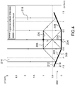
- the local concentrator 202 is here assumed to be located at the top of the balloon, and follow on the outer surface portion of the envelope a rectilinear path 204, overhung by a corresponding paired line 206 of bifacial solar cells.
- the curvature of a band of the outer surface of the balloon, about ten centimeters wide, located around and in the vicinity of the rectilinear path 204 is assumed to be close to that of a plane.
- the direct solar irradiance of the cells of line 206 is assumed to come vertically from the top of the Figure 4 , perpendicular to the plane tangent to the path 204 at the top of the balloon.
- the local concentrator 202 comprises a reflector 208 having a first reflecting face 212 and a second rear face 214.
- the first reflecting face 212 has a convex shape adapted to converge the solar radiation of two incident beams 216, 218 to the rear faces 220 of the bifacial solar cells of the line 206.
- the second rear face 214 has a concave face, fixed along the longitudinal path 204.
- the first reflecting surface 212 comprises a first surface strip 224, here planar, masked by the solar cells of the associated line 206, the second and third strips 226, 228, here plane, of active surfaces participating in the concentration of solar radiation, here the incident beams 216, 218 to the rear faces of the cells of the line 206.
- the surfaces of the first reflective convex faces have longitudinal cross-section contours whose shape is a succession of an odd integer N greater than or equal to 5, of segments approaching a conical portion.
- the integer number N of segments is preferably among the integers 3, 5 and 7.
- the local concentrator 202 by its simple shape in a succession of segmented plane mirrors, can be made of metal foils, for example aluminum, or any other material making it possible to produce a mirror of the solar radiation at least in the active frequency band for photovoltaic and in-band thermal radiation.
- the first masked band 224 does not intervene in the concentration of the photovoltaic radiation, and it may be sufficient for the material constituting it to be able to reflect the thermal radiation emitted by the photovoltaic photovoltaic bifacial solar cells. Indeed, the bifacial solar cells emit an intense thermal flux to the outer envelope and the first masked strip 224 of the reflector 212 due to its thermal properties makes it possible to reflect the intense heat flow towards the outside of the balloon.
- the width of a photovoltaic cell of the line 206 is equal to 10 cm while the height h of overhang relative to the straight path 204 followed along the outer surface portion is equal to 10 cm.
- the widths of the mirror panels formed by the first, second and third strips are each equal to 10 cm.
- the inclinations of the second and third bands are adjusted relative to the first band so as to maximize the concentration factor which is here equal to 2.41, the concentration factor being defined as the ratio of the sum of the solar fluxes received by the front face and the rear face of the bifacial solar cell on the solar flux received by the front face alone.
- the shape of a solar cell line pair - local concentrator having the same pattern as the line 204 - local concentrator 202 pair and angularly away from it by a predetermined angle a, and optimizing the supply electrical energy of the solar cells of its line, is obtained by pivotally pivoting the pair 204 of solar cells - local concentrator 202 around the longitudinal median axis of the first band of the predetermined angle a, the direction of solar direct illumination remaining unchanged, ie vertical on the Figure 4 and then tilting the faces of the line 204 about their common longitudinal median axis so as to align the normals of the front faces of the cells with the predetermined direction of solar illumination, and then adjust the inclinations of the second and third bands relative to to the first band so as to maximize the return of solar radiation on the rear faces of the line solar cells 204 whose inclination has previously been adjusted.
- the local concentrator 302 is decomposed into a longitudinal sequence of an integer T greater than or equal to 2, of longitudinal sections of local concentrator, paired either in a first case with a straight line of solar cells of the same radial level, or in a second case with a line of solar cells segmented at different radial levels with respect to the longitudinal axis as a function of the longitudinal level.
- the first case corresponds to the example of Figure 4 an outer surface portion of the balloon covered by the compact solar generator, comparable to a single longitudinal extension cylinder tile.
- the second case corresponds to an outer surface portion of the balloon covered by the compact solar generator, comparable to a longitudinal succession of T tiles cylinders whose diameters are different and vary depending on the longitudinal level.
- the line of solar cells paired with the local concentrator 302, is designated by the reference numeral 304.
- the local concentrator 302 is here assumed to follow on the outer surface portion of the envelope, a path 306 whose radial level is constant or varies slightly in steps of identical length to that of a tile, the path being overhung to a height constant h by the corresponding 304 line of solar cells.
- the curvature of a strip of the outer surface of the balloon, about ten centimeters wide, located around and in the vicinity of the rectilinear path 304 is assumed to be close to that of a plane.
- section 312 of the T sections of the local concentrator 302 is illustrated.
- the section 312 shares the same pattern with the other sections of the local concentrator, and with the sections of the other local concentrators.
- the geometry of the pattern is unchanged in the first case of outer surface portion covered and varies in the second case depending on the diameter of the tile covered among T tiles.
- the local concentrator section 312 comprises an elementary reflector having a first reflective elementary face 322 and a second elementary rear face 324.
- the first elementary reflective surface 322 has a convex shape adapted to converge the solar radiation of two incident beams, not shown on FIG. Figure 5 towards the rear faces 330 of the bifacial solar cells of the line 304 situated at the same longitudinal level.
- the second rear elementary face 324 has a concave face fixed to the portion of the outer surface of the outer envelope along the longitudinal path 306.
- the first elementary reflecting surface 322 comprises a first elementary surface band 334, here planar, masked by the solar cells of the associated line 304, second and third elementary strips 336, 338, here plane, of active surfaces participating in the concentration of the solar radiation to the backs of the cells of line 304.
- the surfaces of the first reflective convex elementary faces have longitudinal cross-section contours whose shape is a succession of an odd integer N greater than or equal to 5, of segments approaching a conical portion.
- the integer number N of segments is preferably among the integers 3, 5 and 7.
- the T longitudinal sections of the local concentrator 302 by their simple shape in a succession of elementary planar segmented mirrors, can be made by metal foils, for example aluminum, or any other material making it possible to produce a mirror of the solar radiation at least in the active frequency band for photovoltaic conversion.
- the first masked elementary band 334 does not intervene in the concentration of photovoltaic radiation, and it may be sufficient for the material constituting it to be able to reflect the thermal radiation emitted by the photovoltaic photovoltaic bifacial solar cells. Indeed, the bifacial solar cells emit an intense thermal flux towards the outer envelope and the first masked elementary strip 334 of the reflector 322 by its thermal properties makes it possible to reflect the intense thermal flux towards the outside of the balloon.
- the width of a photovoltaic cell of the line 304 is equal to 10 cm while the height h of overhang relative to the rectilinear path 306 followed along the outer surface portion is equal to 10 cm.
- the widths of the mirror panels formed by the first, second and third elementary bands are each equal to 10 cm, their common length here being equal to 1 meter. The inclinations of the second and third elementary bands are adjusted relative to the first elementary band so as to maximize the concentration factor.
- the solar cell line 304 matched to the local concentrator 302, is attached to the outer surface portion of the outer envelope through each section of the local concentrator 302, and a pile 352 of poles 356, interposed and fixed between the line 304 of the photovoltaic solar cells and the T sections of the paired local concentrator.
- the material constituting the posts is mechanically rigid, electrically insulating and not very absorbent vis-à-vis solar radiation.
- each local concentrator of the second set of T sections having a pattern independent of the local concentrator and the longitudinal assembly level of the section, in addition to simplifying the manufacturing process and assembly of the concentrator and its integration into the generator solar, maximizes the return of solar radiation to the solar cells of the first set by adjusting the size and shape of the sections according to their longitudinal location and the radial position of the local concentrators in which they are integrated.
- sections of local concentrators adjacent to each other and of the same longitudinal level can be grouped and integrated on flat panels if the curvature of the outer surface portion at the longitudinal level allows it.
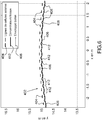
- a compact solar generator 402 of the type defined in the Figures 3A and 3B and having local concentrators of the type of that of the Figure 4 or sections of concentrators of the type of Figure 5 here comprises fifteen lines 404 of solar cells respectively overhanging fifteen segments 406 of different generatrices of a portion of a cylindrical surface 408 having the shape of a tile.
- the cylindrical surface is here a cylinder of radius equal to 15 meters and the segments 406, forming straight paths of the portion 408 of the outer surface of the balloon and represented end on the Figure 6 by points, are mutually parallel.
- Each line 404 is paired with a different local concentrator 412, attached to the outer surface portion 408 and having a reflector 414 with three segmented plane mirrors. Like the Figures 4 and 5 each line 404 of solar cells overhangs its associated path 406 and the median mirror pan of the paired local concentrator reflector by a constant height h relative to the associated path.
- each concentrator has been adjusted to ensure optimum return of solar radiation to the bifacial cells, the inclinations of the faces of the cells having been previously adjusted to make their normal parallel to a predetermined direction relative to the balloon, here the vertical on the Figure 6 .
- the height h of overhanging solar cell lines, and as a result the thickness of the solar generator is modified to increase the efficiency of all local concentrators. He appears on the Figure 8 by increasing the overhead height h of the solar cell line 206 and adjusting the inclination of the second and third strips 226, 228 with respect to the first masked band 204, the width of the incident beams 382, 384 returned by the Reflector 212 on the rear faces of the cells is increased, and as a result the efficiency of the local concentrator 202 is increased.
- the size of the local concentrators as well as their shape are first adjusted to optimize the concentration factor to a desired value.
- the shapes of the concentrators are then projected and re-optimized locally to maximize the return of solar flux to the solar cells, using an optical calculation code such as "codeV".
- codeV optical calculation code
- the ratio of the overhead height h of the solar cell lines to the distance r separating the outer surface portion from the longitudinal central axis of the outer surface is less than or equal to 1/30.
- the height of overhang will be between 0.1 and 0.2 meters for a balloon radius of 15 meters relative to the longitudinal axis, which corresponds to a ratio between 1/50 and 1/75.
- stratospheric balloon described above can be replaced by any other type of balloon evolving in other layers of the atmosphere, keeping identically the characteristics of the invention.
Landscapes
- Engineering & Computer Science (AREA)
- Mechanical Engineering (AREA)
- Aviation & Aerospace Engineering (AREA)
- Photovoltaic Devices (AREA)
- Life Sciences & Earth Sciences (AREA)
- Sustainable Energy (AREA)
Claims (15)
- Lenkbarer Ballon, welcher mit einem kompakten Solargenerator mit Konzentration ausgestattet ist, um den Ballon im Flug mit elektrischer Energie anhand von Sonnenstrahlung zu versorgen,
wobei der lenkbare Ballon eine äußere Hülle (108), ein in der äußeren Hülle (108) enthaltenes Trägergas und einen kompakten Solargenerator (104) mit Konzentration beinhaltet,
wobei die äußere Hülle (108) eine äußere, geschlossene Fläche (114) länglicher Form entlang einer vorbestimmten Längsmittelachse (116) besitzt,
wobei der kompakte Solargenerator (104) Folgendes beinhaltet:eine erste Gruppe (122) aus mindestens einer Reihe (124, 126, 128, 130, 132; 206; 304) von zweiseitigen Photovoltaik-Solarzellen (134), angeordnet oberhalb von und in einer vorbestimmten Höhe h eines kompakten Abschnitts (138) einer Spitze (140) der äußeren Fläche (114), wobei jede Reihe (124, 126, 128, 130, 132; 206; 304) von zweiseitigen Solarzellen konfiguriert ist, um überhängend einem Längsweg (144, 146, 148, 150, 152; 204; 306) zu folgen, der auf dem kompakten Abschnitt (138) einer Spitze der äußeren Fläche (114) trassiert ist und welcher in einer radialen Projektionsebene enthalten ist, welche die Längsmittelachse (116) der äußeren Fläche (114) enthält; undeinen Konzentrator (136) für Sonnenstrahlung, um Sonnenstrahlen auf Rückseiten der zweiseitigen Solarzellen der ersten Gruppe (122) konvergierend auszurichten;wobei der lenkbare Ballon dadurch gekennzeichnet ist, dassder Konzentrator (136) für Sonnenstrahlung eine zweite Gruppe (156) aus mindestens einem lokalen Konzentrator (164, 166, 168, 170, 172; 202; 302) für Sonnenstrahlung ist, bei welcher jeder lokale Konzentrator (164, 166, 168, 170, 172; 202; 302) mit einer entsprechenden Reihe (124, 126, 128, 130, 132; 206; 304) von Solarzellen gepaart ist, und einen Reflektor (174, 176, 178, 180, 182; 208; 318) beinhaltet, der eine erste reflektierende Seite (212; 322) besitzt, welche eine Fläche konvexer Form besitzt, welche geeignet ist, die Sonnenstrahlung auf die Rückseiten (220; 330) der Solarzellen der gepaarten Reihe (124, 126, 128, 130, 132; 206; 304) konvergierend auszurichten, und der eine zweite konkave Seite (214; 324) besitzt, Rückseite der ersten konvexen Seite (212 ; 322), welche an der äußeren Fläche (114) der äußeren Hülle (108) entlang des von der entsprechenden Reihe von Solarzellen überhangenen länglichen Wegs befestigt ist, unddie erste und die zweite Seite der lokalen Sonnenstrahlungs-Konzentratoren (164, 166, 168, 170, 172) so dimensioniert und untereinander angeordnet sind, dass die Konzentratoren getrennt oder aneinander angrenzend sind. - Lenkbarer Ballon, ausgestattet mit einem kompakten Solargenerator mit Konzentration nach Anspruch 1, bei welchem
die Geometrie der Reihen (124, 126, 128, 130, 132; 206; 304) der Solarzellen und der Seiten der lokalen Konzentratoren (164, 166, 168, 170, 172; 202; 302) so angepasst ist, dass ein konstanter solarer Fluss und ein solarer Fluss gleicher Intensität unabhängig von der Position der Photovoltaik-Solarzelle auf dem Abschnitt der äußeren Fläche gewährleistet ist. - Lenkbarer Ballon, ausgestattet mit einem kompakten Solargenerator mit Konzentration nach Anspruch 1, bei welchem
jede zweiseitige Zelle eine Vorder- und eine Rückseite besitzt, und
die zweiseitigen Zellen der Reihen (124, 126, 128, 130, 132; 206; 304) der ersten Gruppe (122) in Bezug auf Positionierung und Ausrichtung in Bezug auf den Abschnitt der äußeren Fläche des Ballons, an welcher die Zellen befestigt sind, so angeordnet sind, dass die Normalen der Vorderseiten aller Solarzellen in eine selbe vorbestimmte Beleuchtungsrichtung in Bezug auf den Ballon weisen. - Lenkbarer Ballon, ausgestattet mit einem kompakten Solargenerator mit Konzentration nach einem der Ansprüche 1 bis 3, bei welchem
die Fläche der ersten konvexen, reflektierenden Seite jedes lokalen Konzentrators (164, 166, 168, 170, 172; 202) einen ersten durch die Solarzellen der dazugehörigen Reihe (124, 126, 128, 130, 132; 206) verdeckten Streifen beinhaltet, wobei ein zweiter und ein dritter aktive Streifen an der Konzentration der Sonnenstrahlung mitwirken,
wobei der erste und der zweite aktive Streifen aus einem gegenüber der Strahlung, welche in den Frequenzbändern der photovoltaischen Umwandlung enthalten ist, reflektierenden Material bestehen, und
der erste verdeckte Streifen aus einem Material besteht, welches gegenüber der thermischen Strahlung reflektierend ist, welche von den Photovoltaikzellen abgegeben wird, wenn diese aktiv sind. - Lenkbarer Ballon, ausgestattet mit einem kompakten Solargenerator mit Konzentration nach Anspruch 4, bei welchem
die Fläche der ersten konvexen, reflektierenden Seite jedes lokalen Konzentrators (164, 166, 168, 170, 172; 202) vollständig aus einem Material besteht, welches gleichzeitig gegenüber der Strahlung reflektierend ist, welche in den bei der photovoltaischen Umwandlung mitwirkenden Frequenzbändern enthalten ist, und gegenüber der thermischen Strahlung reflektierend ist, welche von den Photovoltaikzellen und von der Sonne abgegeben wird. - Lenkbarer Ballon, ausgestattet mit einem kompakten Solargenerator mit Konzentration nach einem der Ansprüche 1 bis 5, bei welchem
jede Reihe (124, 126, 128, 130, 132; 206) von Solarzellen der ersten Gruppe an dem Abschnitt der äußeren Fläche der äußeren Hülle über den dazugehörigen lokalen Konzentrator und ein Pfahlwerk (352) aus Pfosten (356) befestigt ist, welche zwischen der Reihe (124, 126, 128, 130, 132; 206) der Photovoltaikzellen und dem gepaarten lokalen Konzentrator (164, 166, 168, 170, 172; 202) zwischengeschaltet und befestigt sind,
wobei das die Pfosten (356) bildende Material starr, elektrisch isolierend und kaum gegenüber der Sonnenstrahlung absorbierend ist. - Lenkbarer Ballon, ausgestattet mit einem kompakten Solargenerator mit Konzentration nach einem der Ansprüche 1 bis 6, bei welchem
die Flächen der ersten konvexen, reflektierenden Seiten Längsquerschnittkonturen besitzen, deren Form ein konischer Abschnitt oder eine Kurve ist, welche sich einem konischen Abschnitt annähert. - Lenkbarer Ballon, ausgestattet mit einem kompakten Solargenerator mit Konzentration nach Anspruch 7, bei welchem
die Flächen der ersten konvexen, reflektierenden Seiten Längsquerschnittkonturen besitzen, deren Form eine Abfolge einer ungeraden Ganzzahl N von Segmenten ist, welche sich einem konischen Abschnitt annähern, wobei die ungerade Ganzzahl N von Segmenten vorzugsweise in den Ganzzahlen 3, 5 und 7 beinhaltet ist. - Lenkbarer Ballon, ausgestattet mit einem kompakten Solargenerator mit Konzentration nach einem der Ansprüche 1 bis 8, bei welchem
das Verhältnis zwischen der Überhangshöhe h der Reihen von Solarzellen und dem Abstand r, welcher den Abschnitt der äußeren Fläche von der Längsmittelachse der äußeren Fläche trennt, kleiner oder gleich 1/15 ist, vorzugsweise kleiner oder gleich 1/30. - Lenkbarer Ballon, ausgestattet mit einem kompakten Solargenerator mit Konzentration nach einem der Ansprüche 1 bis 9, bei welchem
der kompakte Solargenerator (104) eine Ganzzahl NL von Reihen von Solarzellen und von lokalen Konzentratoren (302) beinhaltet, und
jeder lokale Konzentrator (302) sich in eine Längssequenz einer Ganzzahl T, die größer oder gleich 2 ist, von Längsabschnitten (312) eines lokalen Konzentrators gliedert, welche in einem ersten Fall mit einer geraden Reihe (304) von Solarzellen gleicher radialer Stufe in Bezug auf die Längsachse, oder in einem zweiten Fall, mit einer Reihe (304) von Solarzellen, welche in unterschiedliche radiale Stufen in Bezug auf die Längsachse segmentiert ist, gepaart sind. - Lenkbarer Ballon, ausgestattet mit einem kompakten Solargenerator mit Konzentration nach Anspruch 10, bei welchem
jeder Längsabschnitt (312) einen Elementarreflektor (318) beinhaltet, der eine erste reflektierende Elementarseite (322) besitzt, welche eine Fläche konvexer Form besitzt, welche geeignet ist, die Sonnenstrahlung auf die Rückseiten (330) der Solarzellen der gepaarten Reihe (304) gleicher Längsstufe konvergierend auszurichten, und der eine zweite Elementarseite (324) besitzt, Rückseite der zweiten Elementarseite und konkav, welche an dem Abschnitt der äußeren Fläche der äußeren Hülle entlang des von der gepaarten Reihe von Solarzellen überhangenen Wegs befestigt ist. - Lenkbarer Ballon, ausgestattet mit einem kompakten Solargenerator mit Konzentration nach Anspruch 11, bei welchem
die Geometrie der Reihen (304) der Solarzellen und der Seiten (322, 324) der Längsabschnitte (312) der lokalen Konzentratoren (302) so angepasst ist, dass ein konstanter solarer Fluss und ein solarer Fluss gleicher Intensität unabhängig von der Position der Photovoltaik-Solarzelle auf dem Abschnitt der äußeren Fläche gewährleistet ist. - Lenkbarer Ballon, ausgestattet mit einem kompakten Solargenerator mit Konzentration nach einem der Ansprüche 11 bis 12, bei welchem
die Fläche der ersten reflektierenden Elementarseite (322) jedes Abschnitts (312) eines lokalen Konzentrators (302) einen ersten Elementarstreifen (334) beinhaltet, welcher von den Solarzellen gleicher Längsstufe der gepaarten Linie verdeckt wird, wobei ein zweiter und ein dritter aktiver Elementarstreifen (336, 338) an der Konzentration der Sonnenstrahlung mitwirken,
wobei der erste und der zweite aktive Elementarstreifen (336, 338) aus einem gegenüber der Strahlung, welche in den bei der photovoltaischen Umwandlung mitwirkenden Frequenzbändern enthalten ist, reflektierenden Material bestehen, und
der erste verdeckte Elementarstreifen (334) aus einem Material besteht, welches gegenüber der thermischen Strahlung reflektierend ist, welche von den Photovoltaikzellen abgegeben wird, wenn diese aktiv sind. - Lenkbarer Ballon, ausgestattet mit einem kompakten Solargenerator mit Konzentration nach einem der Ansprüche 11 bis 13, bei welchem
die Flächen der ersten konvexen, reflektierenden Elementarseiten (322) Längsquerschnittkonturen besitzen, deren Form ein konischer Abschnitt oder eine Kurve ist, welche sich einem konischen Abschnitt annähert. - Lenkbarer Ballon, ausgestattet mit einem kompakten Solargenerator mit Konzentration nach Anspruch 14, bei welchem
die Flächen der ersten konvexen, reflektierenden Elementarseiten (322) Längsquerschnittkonturen besitzen, deren Form eine Abfolge einer ungeraden Ganzzahl N von Segmenten ist, welche sich einem konischen Abschnitt annähern, wobei die ungerade Ganzzahl N von Segmenten vorzugsweise in den Ganzzahlen 3, 5 und 7 beinhaltet ist.
Applications Claiming Priority (1)
| Application Number | Priority Date | Filing Date | Title |
|---|---|---|---|
| FR1601064A FR3053657B1 (fr) | 2016-07-08 | 2016-07-08 | Ballon dirigeable equipe d'un generateur solaire compact a concentration locale utilisant des lignes de cellules solaires bifaciales |
Publications (2)
| Publication Number | Publication Date |
|---|---|
| EP3266703A1 EP3266703A1 (de) | 2018-01-10 |
| EP3266703B1 true EP3266703B1 (de) | 2018-10-17 |
Family
ID=57286543
Family Applications (1)
| Application Number | Title | Priority Date | Filing Date |
|---|---|---|---|
| EP17169421.9A Active EP3266703B1 (de) | 2016-07-08 | 2017-05-04 | Lenkbarer ballon, der mit einem kompakten solargenerator mit lokaler konzentration ausgestattet ist, der reihen von zweiseitigen solarzellen verwendet |
Country Status (6)
| Country | Link |
|---|---|
| US (1) | US20180013381A1 (de) |
| EP (1) | EP3266703B1 (de) |
| JP (1) | JP2018002133A (de) |
| CN (1) | CN107585284A (de) |
| CA (1) | CA2972262A1 (de) |
| FR (1) | FR3053657B1 (de) |
Families Citing this family (10)
| Publication number | Priority date | Publication date | Assignee | Title |
|---|---|---|---|---|
| US10518339B2 (en) * | 2017-03-22 | 2019-12-31 | Kennametal Inc. | Tangentially mounted cutting insert with angled seating surface and recessed clearance surface |
| FR3080361B1 (fr) * | 2018-04-18 | 2020-12-04 | Zephyr Exalto | Aerostat presentant un ballon a double enveloppe |
| FR3080965B1 (fr) * | 2018-05-04 | 2020-05-29 | Commissariat A L'energie Atomique Et Aux Energies Alternatives | Systeme d'energie solaire photovoltaique a miroirs escamotables |
| JP7206133B2 (ja) * | 2019-02-28 | 2023-01-17 | 京セラ株式会社 | 太陽光発電システム及び太陽光発電装置 |
| CN110032052B (zh) * | 2019-04-25 | 2022-01-18 | 珠海毅希科技有限公司 | 一种可预热硒鼓 |
| CN111959701A (zh) * | 2020-09-01 | 2020-11-20 | 常州工学院 | 一种具备海上定位功能的双层光伏增效装置 |
| CN112061408B (zh) * | 2020-09-17 | 2022-05-24 | 广州鼎奥科技有限公司 | 一种带有气囊保护装置的无人机 |
| CN113158130B (zh) * | 2021-03-09 | 2024-04-19 | 中国电建集团华东勘测设计研究院有限公司 | 一种双面组件主轴遮挡处辐射率的计算方法、设备和介质 |
| CN113788136B (zh) * | 2021-11-10 | 2022-04-22 | 中国空气动力研究与发展中心低速空气动力研究所 | 一种中轴通气聚光飞艇 |
| CN121036679B (zh) * | 2025-10-13 | 2026-04-10 | 陕西恒盛智能电气有限公司 | 一种储能电池舱的光伏储能模块 |
Family Cites Families (10)
| Publication number | Priority date | Publication date | Assignee | Title |
|---|---|---|---|---|
| GB1116140A (en) | 1965-12-10 | 1968-06-06 | Mcculloch Corp | Compression relief mechanism for starting internal combustion engines |
| FR2497927A1 (fr) * | 1981-01-09 | 1982-07-16 | Brych Alfred | Capteur solaire a concentration |
| JPH11238900A (ja) * | 1998-02-20 | 1999-08-31 | Hitachi Ltd | 集光型太陽光発電装置 |
| JP2002314112A (ja) * | 2001-04-16 | 2002-10-25 | Sumitomo 3M Ltd | 光発電システム |
| FR2834584B1 (fr) * | 2002-01-07 | 2005-07-15 | Cit Alcatel | Dispositif concentrateur d'energie solaire pour vehicule spatial et panneau generateur solaire |
| US8020805B2 (en) * | 2006-07-31 | 2011-09-20 | The United States Of America As Represented By The Administrator Of The National Aeronautics And Space Administration | High altitude airship configuration and power technology and method for operation of same |
| FR2982840B1 (fr) * | 2011-11-22 | 2016-01-15 | Thales Sa | Ballon comprenant des moyens photovoltaiques et un dispositif de concentration solaire |
| WO2014028201A2 (en) * | 2012-08-16 | 2014-02-20 | Leonid Goldstein | Airborne concentrated solar photovoltaic system |
| FR3015149A1 (fr) * | 2013-12-18 | 2015-06-19 | Commissariat Energie Atomique | Structure photovoltaique |
| US20160030135A1 (en) * | 2014-07-29 | 2016-02-04 | En-Heng Liu | Drill bit guiding device for dental implant surgery |
-
2016
- 2016-07-08 FR FR1601064A patent/FR3053657B1/fr not_active Expired - Fee Related
-
2017
- 2017-05-04 EP EP17169421.9A patent/EP3266703B1/de active Active
- 2017-05-05 US US15/588,325 patent/US20180013381A1/en not_active Abandoned
- 2017-05-11 JP JP2017094444A patent/JP2018002133A/ja active Pending
- 2017-06-29 CA CA2972262A patent/CA2972262A1/en not_active Abandoned
- 2017-07-07 CN CN201710550249.3A patent/CN107585284A/zh active Pending
Non-Patent Citations (1)
| Title |
|---|
| None * |
Also Published As
| Publication number | Publication date |
|---|---|
| US20180013381A1 (en) | 2018-01-11 |
| CN107585284A (zh) | 2018-01-16 |
| JP2018002133A (ja) | 2018-01-11 |
| EP3266703A1 (de) | 2018-01-10 |
| FR3053657B1 (fr) | 2019-07-19 |
| CA2972262A1 (en) | 2018-01-08 |
| FR3053657A1 (fr) | 2018-01-12 |
Similar Documents
| Publication | Publication Date | Title |
|---|---|---|
| FR3053657B1 (fr) | Ballon dirigeable equipe d'un generateur solaire compact a concentration locale utilisant des lignes de cellules solaires bifaciales | |
| EP0059653B1 (de) | Hohlspiegel mit einer Vielzahl von ebenen Fazetten sowie ein Sonnengenerator mit solch einem Spiegel | |
| EP1982226B1 (de) | Optisches system zur anzeige eines bildes auf der fläche eines sonnenkollektors | |
| EP3084842B1 (de) | Fotovoltaikstruktur | |
| EP0083548B1 (de) | Vorrichtung zur Sammlung und Verwendung der gesamten Sonnenstrahlung | |
| EP3118103A1 (de) | Ballon, der mit einem solargenerator mit hoher konzentration ausgestattet ist und eine optimierte anordnung von solarzellen zur stromversorgung im flug dieses ballons nutzt | |
| EP2597031B1 (de) | Ballon mit photovoltaischen Mitteln und eine Vorrichtung zu Bündeln des Sonnenlichts | |
| FR2889597A1 (fr) | Plaque texturee a motifs asymetriques | |
| FR2939913A1 (fr) | Panneau solaire permettant la visualisation d'une image. | |
| EP2534430B1 (de) | Sonnenkollektor mit fresnel-spiegeln | |
| EP0001461A1 (de) | Anordnung zur Umwandlung von Sonnenenergie in elektrische Energie des Typs bestehend aus photovoltaischer Zelle und optischem Konzentrator | |
| US20060249143A1 (en) | Reflecting photonic concentrator | |
| EP1436197B1 (de) | Optischer oberflächenreflektor für raumfahrzeug, wie zum beispiel einen geostationären satelliten | |
| FR2951251A1 (fr) | Systeme de production d'energie combinant l'energie solaire thermique et l'energie photovoltaique | |
| WO2021063979A1 (fr) | Système optique | |
| EP2620987B1 (de) | Geräte und Systeme zur Konzentration/Rückgewinnung von Sonnenenergie, und Anwendungen für die Industrie und Privathaushalte | |
| EP3793085B1 (de) | Schwimmende fotovoltaikstruktur | |
| EP3484047B1 (de) | Fotovoltaik-sonnenenergiesystem mit verbesserter ausbeute | |
| EP2161605A1 (de) | Beobachtungssystem mit Schutzeinheit | |
| FR2976055A1 (fr) | Collecteur solaire plan d'epaisseur reduite et installation de recuperation de l'energie solaire comportant au moins un tel collecteur | |
| FR3157523A1 (fr) | Concentrateur d’un rayonnement solaire, et centrale solaire correspondante | |
| FR3017195A1 (fr) | Reflecteur secondaire pour centrale solaire a concentration lineaire | |
| WO2024172805A2 (en) | Compact concentrator for microscale space photovoltaic systems | |
| FR3079349A1 (fr) | Panneau solaire | |
| FR2935786A1 (fr) | Capteur solaire thermique |
Legal Events
| Date | Code | Title | Description |
|---|---|---|---|
| PUAI | Public reference made under article 153(3) epc to a published international application that has entered the european phase |
Free format text: ORIGINAL CODE: 0009012 |
|
| STAA | Information on the status of an ep patent application or granted ep patent |
Free format text: STATUS: THE APPLICATION HAS BEEN PUBLISHED |
|
| AK | Designated contracting states |
Kind code of ref document: A1 Designated state(s): AL AT BE BG CH CY CZ DE DK EE ES FI FR GB GR HR HU IE IS IT LI LT LU LV MC MK MT NL NO PL PT RO RS SE SI SK SM TR |
|
| AX | Request for extension of the european patent |
Extension state: BA ME |
|
| STAA | Information on the status of an ep patent application or granted ep patent |
Free format text: STATUS: REQUEST FOR EXAMINATION WAS MADE |
|
| 17P | Request for examination filed |
Effective date: 20180123 |
|
| RBV | Designated contracting states (corrected) |
Designated state(s): AL AT BE BG CH CY CZ DE DK EE ES FI FR GB GR HR HU IE IS IT LI LT LU LV MC MK MT NL NO PL PT RO RS SE SI SK SM TR |
|
| RIC1 | Information provided on ipc code assigned before grant |
Ipc: H01L 31/056 20140101ALI20180516BHEP Ipc: B64B 1/44 20060101ALI20180516BHEP Ipc: B64B 1/06 20060101ALI20180516BHEP Ipc: B64B 1/40 20060101ALI20180516BHEP Ipc: H01L 31/068 20120101ALI20180516BHEP Ipc: B64B 1/14 20060101AFI20180516BHEP |
|
| GRAP | Despatch of communication of intention to grant a patent |
Free format text: ORIGINAL CODE: EPIDOSNIGR1 |
|
| STAA | Information on the status of an ep patent application or granted ep patent |
Free format text: STATUS: GRANT OF PATENT IS INTENDED |
|
| INTG | Intention to grant announced |
Effective date: 20180718 |
|
| GRAS | Grant fee paid |
Free format text: ORIGINAL CODE: EPIDOSNIGR3 |
|
| GRAA | (expected) grant |
Free format text: ORIGINAL CODE: 0009210 |
|
| STAA | Information on the status of an ep patent application or granted ep patent |
Free format text: STATUS: THE PATENT HAS BEEN GRANTED |
|
| AK | Designated contracting states |
Kind code of ref document: B1 Designated state(s): AL AT BE BG CH CY CZ DE DK EE ES FI FR GB GR HR HU IE IS IT LI LT LU LV MC MK MT NL NO PL PT RO RS SE SI SK SM TR |
|
| REG | Reference to a national code |
Ref country code: GB Ref legal event code: FG4D Free format text: NOT ENGLISH |
|
| REG | Reference to a national code |
Ref country code: CH Ref legal event code: EP |
|
| REG | Reference to a national code |
Ref country code: IE Ref legal event code: FG4D Free format text: LANGUAGE OF EP DOCUMENT: FRENCH |
|
| REG | Reference to a national code |
Ref country code: DE Ref legal event code: R096 Ref document number: 602017000632 Country of ref document: DE Ref country code: AT Ref legal event code: REF Ref document number: 1053678 Country of ref document: AT Kind code of ref document: T Effective date: 20181115 |
|
| REG | Reference to a national code |
Ref country code: NL Ref legal event code: MP Effective date: 20181017 |
|
| REG | Reference to a national code |
Ref country code: LT Ref legal event code: MG4D |
|
| REG | Reference to a national code |
Ref country code: AT Ref legal event code: MK05 Ref document number: 1053678 Country of ref document: AT Kind code of ref document: T Effective date: 20181017 |
|
| PG25 | Lapsed in a contracting state [announced via postgrant information from national office to epo] |
Ref country code: NL Free format text: LAPSE BECAUSE OF FAILURE TO SUBMIT A TRANSLATION OF THE DESCRIPTION OR TO PAY THE FEE WITHIN THE PRESCRIBED TIME-LIMIT Effective date: 20181017 |
|
| PG25 | Lapsed in a contracting state [announced via postgrant information from national office to epo] |
Ref country code: ES Free format text: LAPSE BECAUSE OF FAILURE TO SUBMIT A TRANSLATION OF THE DESCRIPTION OR TO PAY THE FEE WITHIN THE PRESCRIBED TIME-LIMIT Effective date: 20181017 Ref country code: IS Free format text: LAPSE BECAUSE OF FAILURE TO SUBMIT A TRANSLATION OF THE DESCRIPTION OR TO PAY THE FEE WITHIN THE PRESCRIBED TIME-LIMIT Effective date: 20190217 Ref country code: LT Free format text: LAPSE BECAUSE OF FAILURE TO SUBMIT A TRANSLATION OF THE DESCRIPTION OR TO PAY THE FEE WITHIN THE PRESCRIBED TIME-LIMIT Effective date: 20181017 Ref country code: BG Free format text: LAPSE BECAUSE OF FAILURE TO SUBMIT A TRANSLATION OF THE DESCRIPTION OR TO PAY THE FEE WITHIN THE PRESCRIBED TIME-LIMIT Effective date: 20190117 Ref country code: NO Free format text: LAPSE BECAUSE OF FAILURE TO SUBMIT A TRANSLATION OF THE DESCRIPTION OR TO PAY THE FEE WITHIN THE PRESCRIBED TIME-LIMIT Effective date: 20190117 Ref country code: HR Free format text: LAPSE BECAUSE OF FAILURE TO SUBMIT A TRANSLATION OF THE DESCRIPTION OR TO PAY THE FEE WITHIN THE PRESCRIBED TIME-LIMIT Effective date: 20181017 Ref country code: AT Free format text: LAPSE BECAUSE OF FAILURE TO SUBMIT A TRANSLATION OF THE DESCRIPTION OR TO PAY THE FEE WITHIN THE PRESCRIBED TIME-LIMIT Effective date: 20181017 Ref country code: PL Free format text: LAPSE BECAUSE OF FAILURE TO SUBMIT A TRANSLATION OF THE DESCRIPTION OR TO PAY THE FEE WITHIN THE PRESCRIBED TIME-LIMIT Effective date: 20181017 Ref country code: LV Free format text: LAPSE BECAUSE OF FAILURE TO SUBMIT A TRANSLATION OF THE DESCRIPTION OR TO PAY THE FEE WITHIN THE PRESCRIBED TIME-LIMIT Effective date: 20181017 Ref country code: FI Free format text: LAPSE BECAUSE OF FAILURE TO SUBMIT A TRANSLATION OF THE DESCRIPTION OR TO PAY THE FEE WITHIN THE PRESCRIBED TIME-LIMIT Effective date: 20181017 |
|
| PG25 | Lapsed in a contracting state [announced via postgrant information from national office to epo] |
Ref country code: SE Free format text: LAPSE BECAUSE OF FAILURE TO SUBMIT A TRANSLATION OF THE DESCRIPTION OR TO PAY THE FEE WITHIN THE PRESCRIBED TIME-LIMIT Effective date: 20181017 Ref country code: RS Free format text: LAPSE BECAUSE OF FAILURE TO SUBMIT A TRANSLATION OF THE DESCRIPTION OR TO PAY THE FEE WITHIN THE PRESCRIBED TIME-LIMIT Effective date: 20181017 Ref country code: AL Free format text: LAPSE BECAUSE OF FAILURE TO SUBMIT A TRANSLATION OF THE DESCRIPTION OR TO PAY THE FEE WITHIN THE PRESCRIBED TIME-LIMIT Effective date: 20181017 Ref country code: PT Free format text: LAPSE BECAUSE OF FAILURE TO SUBMIT A TRANSLATION OF THE DESCRIPTION OR TO PAY THE FEE WITHIN THE PRESCRIBED TIME-LIMIT Effective date: 20190217 Ref country code: GR Free format text: LAPSE BECAUSE OF FAILURE TO SUBMIT A TRANSLATION OF THE DESCRIPTION OR TO PAY THE FEE WITHIN THE PRESCRIBED TIME-LIMIT Effective date: 20190118 |
|
| REG | Reference to a national code |
Ref country code: DE Ref legal event code: R097 Ref document number: 602017000632 Country of ref document: DE |
|
| PG25 | Lapsed in a contracting state [announced via postgrant information from national office to epo] |
Ref country code: DK Free format text: LAPSE BECAUSE OF FAILURE TO SUBMIT A TRANSLATION OF THE DESCRIPTION OR TO PAY THE FEE WITHIN THE PRESCRIBED TIME-LIMIT Effective date: 20181017 Ref country code: IT Free format text: LAPSE BECAUSE OF FAILURE TO SUBMIT A TRANSLATION OF THE DESCRIPTION OR TO PAY THE FEE WITHIN THE PRESCRIBED TIME-LIMIT Effective date: 20181017 Ref country code: CZ Free format text: LAPSE BECAUSE OF FAILURE TO SUBMIT A TRANSLATION OF THE DESCRIPTION OR TO PAY THE FEE WITHIN THE PRESCRIBED TIME-LIMIT Effective date: 20181017 |
|
| PLBE | No opposition filed within time limit |
Free format text: ORIGINAL CODE: 0009261 |
|
| STAA | Information on the status of an ep patent application or granted ep patent |
Free format text: STATUS: NO OPPOSITION FILED WITHIN TIME LIMIT |
|
| PG25 | Lapsed in a contracting state [announced via postgrant information from national office to epo] |
Ref country code: SK Free format text: LAPSE BECAUSE OF FAILURE TO SUBMIT A TRANSLATION OF THE DESCRIPTION OR TO PAY THE FEE WITHIN THE PRESCRIBED TIME-LIMIT Effective date: 20181017 Ref country code: SM Free format text: LAPSE BECAUSE OF FAILURE TO SUBMIT A TRANSLATION OF THE DESCRIPTION OR TO PAY THE FEE WITHIN THE PRESCRIBED TIME-LIMIT Effective date: 20181017 Ref country code: EE Free format text: LAPSE BECAUSE OF FAILURE TO SUBMIT A TRANSLATION OF THE DESCRIPTION OR TO PAY THE FEE WITHIN THE PRESCRIBED TIME-LIMIT Effective date: 20181017 Ref country code: RO Free format text: LAPSE BECAUSE OF FAILURE TO SUBMIT A TRANSLATION OF THE DESCRIPTION OR TO PAY THE FEE WITHIN THE PRESCRIBED TIME-LIMIT Effective date: 20181017 |
|
| 26N | No opposition filed |
Effective date: 20190718 |
|
| PG25 | Lapsed in a contracting state [announced via postgrant information from national office to epo] |
Ref country code: MC Free format text: LAPSE BECAUSE OF FAILURE TO SUBMIT A TRANSLATION OF THE DESCRIPTION OR TO PAY THE FEE WITHIN THE PRESCRIBED TIME-LIMIT Effective date: 20181017 |
|
| REG | Reference to a national code |
Ref country code: BE Ref legal event code: MM Effective date: 20190531 |
|
| PG25 | Lapsed in a contracting state [announced via postgrant information from national office to epo] |
Ref country code: LU Free format text: LAPSE BECAUSE OF NON-PAYMENT OF DUE FEES Effective date: 20190504 |
|
| PG25 | Lapsed in a contracting state [announced via postgrant information from national office to epo] |
Ref country code: TR Free format text: LAPSE BECAUSE OF FAILURE TO SUBMIT A TRANSLATION OF THE DESCRIPTION OR TO PAY THE FEE WITHIN THE PRESCRIBED TIME-LIMIT Effective date: 20181017 |
|
| PG25 | Lapsed in a contracting state [announced via postgrant information from national office to epo] |
Ref country code: IE Free format text: LAPSE BECAUSE OF NON-PAYMENT OF DUE FEES Effective date: 20190504 |
|
| PG25 | Lapsed in a contracting state [announced via postgrant information from national office to epo] |
Ref country code: BE Free format text: LAPSE BECAUSE OF NON-PAYMENT OF DUE FEES Effective date: 20190531 |
|
| PG25 | Lapsed in a contracting state [announced via postgrant information from national office to epo] |
Ref country code: LI Free format text: LAPSE BECAUSE OF NON-PAYMENT OF DUE FEES Effective date: 20200531 Ref country code: CH Free format text: LAPSE BECAUSE OF NON-PAYMENT OF DUE FEES Effective date: 20200531 |
|
| PG25 | Lapsed in a contracting state [announced via postgrant information from national office to epo] |
Ref country code: CY Free format text: LAPSE BECAUSE OF FAILURE TO SUBMIT A TRANSLATION OF THE DESCRIPTION OR TO PAY THE FEE WITHIN THE PRESCRIBED TIME-LIMIT Effective date: 20181017 |
|
| PG25 | Lapsed in a contracting state [announced via postgrant information from national office to epo] |
Ref country code: MT Free format text: LAPSE BECAUSE OF FAILURE TO SUBMIT A TRANSLATION OF THE DESCRIPTION OR TO PAY THE FEE WITHIN THE PRESCRIBED TIME-LIMIT Effective date: 20181017 Ref country code: HU Free format text: LAPSE BECAUSE OF FAILURE TO SUBMIT A TRANSLATION OF THE DESCRIPTION OR TO PAY THE FEE WITHIN THE PRESCRIBED TIME-LIMIT; INVALID AB INITIO Effective date: 20170504 |
|
| PG25 | Lapsed in a contracting state [announced via postgrant information from national office to epo] |
Ref country code: SI Free format text: LAPSE BECAUSE OF FAILURE TO SUBMIT A TRANSLATION OF THE DESCRIPTION OR TO PAY THE FEE WITHIN THE PRESCRIBED TIME-LIMIT Effective date: 20181017 |
|
| PG25 | Lapsed in a contracting state [announced via postgrant information from national office to epo] |
Ref country code: MK Free format text: LAPSE BECAUSE OF FAILURE TO SUBMIT A TRANSLATION OF THE DESCRIPTION OR TO PAY THE FEE WITHIN THE PRESCRIBED TIME-LIMIT Effective date: 20181017 |
|
| PGFP | Annual fee paid to national office [announced via postgrant information from national office to epo] |
Ref country code: DE Payment date: 20250416 Year of fee payment: 9 |
|
| PGFP | Annual fee paid to national office [announced via postgrant information from national office to epo] |
Ref country code: GB Payment date: 20250417 Year of fee payment: 9 |
|
| PGFP | Annual fee paid to national office [announced via postgrant information from national office to epo] |
Ref country code: FR Payment date: 20250422 Year of fee payment: 9 |