EP3266594A1 - Verfahren und vorrichtung zur lithographiebasierten generativen fertigung von dreidimensionalen bauteilen - Google Patents
Verfahren und vorrichtung zur lithographiebasierten generativen fertigung von dreidimensionalen bauteilen Download PDFInfo
- Publication number
- EP3266594A1 EP3266594A1 EP16450014.2A EP16450014A EP3266594A1 EP 3266594 A1 EP3266594 A1 EP 3266594A1 EP 16450014 A EP16450014 A EP 16450014A EP 3266594 A1 EP3266594 A1 EP 3266594A1
- Authority
- EP
- European Patent Office
- Prior art keywords
- volume
- focal point
- imaging system
- tub
- optical element
- Prior art date
- Legal status (The legal status is an assumption and is not a legal conclusion. Google has not performed a legal analysis and makes no representation as to the accuracy of the status listed.)
- Granted
Links
Images


Classifications
-
- B—PERFORMING OPERATIONS; TRANSPORTING
- B29—WORKING OF PLASTICS; WORKING OF SUBSTANCES IN A PLASTIC STATE IN GENERAL
- B29C—SHAPING OR JOINING OF PLASTICS; SHAPING OF MATERIAL IN A PLASTIC STATE, NOT OTHERWISE PROVIDED FOR; AFTER-TREATMENT OF THE SHAPED PRODUCTS, e.g. REPAIRING
- B29C64/00—Additive manufacturing, i.e. manufacturing of three-dimensional [3D] objects by additive deposition, additive agglomeration or additive layering, e.g. by 3D printing, stereolithography or selective laser sintering
- B29C64/30—Auxiliary operations or equipment
- B29C64/386—Data acquisition or data processing for additive manufacturing
-
- G—PHYSICS
- G02—OPTICS
- G02B—OPTICAL ELEMENTS, SYSTEMS OR APPARATUS
- G02B27/00—Optical systems or apparatus not provided for by any of the groups G02B1/00 - G02B26/00, G02B30/00
- G02B27/09—Beam shaping, e.g. changing the cross-sectional area, not otherwise provided for
- G02B27/0938—Using specific optical elements
- G02B27/095—Refractive optical elements
- G02B27/0955—Lenses
- G02B27/0966—Cylindrical lenses
-
- B—PERFORMING OPERATIONS; TRANSPORTING
- B29—WORKING OF PLASTICS; WORKING OF SUBSTANCES IN A PLASTIC STATE IN GENERAL
- B29C—SHAPING OR JOINING OF PLASTICS; SHAPING OF MATERIAL IN A PLASTIC STATE, NOT OTHERWISE PROVIDED FOR; AFTER-TREATMENT OF THE SHAPED PRODUCTS, e.g. REPAIRING
- B29C64/00—Additive manufacturing, i.e. manufacturing of three-dimensional [3D] objects by additive deposition, additive agglomeration or additive layering, e.g. by 3D printing, stereolithography or selective laser sintering
- B29C64/10—Processes of additive manufacturing
- B29C64/106—Processes of additive manufacturing using only liquids or viscous materials, e.g. depositing a continuous bead of viscous material
- B29C64/124—Processes of additive manufacturing using only liquids or viscous materials, e.g. depositing a continuous bead of viscous material using layers of liquid which are selectively solidified
- B29C64/129—Processes of additive manufacturing using only liquids or viscous materials, e.g. depositing a continuous bead of viscous material using layers of liquid which are selectively solidified characterised by the energy source therefor, e.g. by global irradiation combined with a mask
- B29C64/135—Processes of additive manufacturing using only liquids or viscous materials, e.g. depositing a continuous bead of viscous material using layers of liquid which are selectively solidified characterised by the energy source therefor, e.g. by global irradiation combined with a mask the energy source being concentrated, e.g. scanning lasers or focused light sources
-
- B—PERFORMING OPERATIONS; TRANSPORTING
- B29—WORKING OF PLASTICS; WORKING OF SUBSTANCES IN A PLASTIC STATE IN GENERAL
- B29C—SHAPING OR JOINING OF PLASTICS; SHAPING OF MATERIAL IN A PLASTIC STATE, NOT OTHERWISE PROVIDED FOR; AFTER-TREATMENT OF THE SHAPED PRODUCTS, e.g. REPAIRING
- B29C64/00—Additive manufacturing, i.e. manufacturing of three-dimensional [3D] objects by additive deposition, additive agglomeration or additive layering, e.g. by 3D printing, stereolithography or selective laser sintering
- B29C64/20—Apparatus for additive manufacturing; Details thereof or accessories therefor
- B29C64/245—Platforms or substrates
-
- B—PERFORMING OPERATIONS; TRANSPORTING
- B29—WORKING OF PLASTICS; WORKING OF SUBSTANCES IN A PLASTIC STATE IN GENERAL
- B29C—SHAPING OR JOINING OF PLASTICS; SHAPING OF MATERIAL IN A PLASTIC STATE, NOT OTHERWISE PROVIDED FOR; AFTER-TREATMENT OF THE SHAPED PRODUCTS, e.g. REPAIRING
- B29C64/00—Additive manufacturing, i.e. manufacturing of three-dimensional [3D] objects by additive deposition, additive agglomeration or additive layering, e.g. by 3D printing, stereolithography or selective laser sintering
- B29C64/20—Apparatus for additive manufacturing; Details thereof or accessories therefor
- B29C64/255—Enclosures for the building material, e.g. powder containers
-
- B—PERFORMING OPERATIONS; TRANSPORTING
- B29—WORKING OF PLASTICS; WORKING OF SUBSTANCES IN A PLASTIC STATE IN GENERAL
- B29C—SHAPING OR JOINING OF PLASTICS; SHAPING OF MATERIAL IN A PLASTIC STATE, NOT OTHERWISE PROVIDED FOR; AFTER-TREATMENT OF THE SHAPED PRODUCTS, e.g. REPAIRING
- B29C64/00—Additive manufacturing, i.e. manufacturing of three-dimensional [3D] objects by additive deposition, additive agglomeration or additive layering, e.g. by 3D printing, stereolithography or selective laser sintering
- B29C64/20—Apparatus for additive manufacturing; Details thereof or accessories therefor
- B29C64/264—Arrangements for irradiation
- B29C64/268—Arrangements for irradiation using laser beams; using electron beams [EB]
-
- B—PERFORMING OPERATIONS; TRANSPORTING
- B29—WORKING OF PLASTICS; WORKING OF SUBSTANCES IN A PLASTIC STATE IN GENERAL
- B29C—SHAPING OR JOINING OF PLASTICS; SHAPING OF MATERIAL IN A PLASTIC STATE, NOT OTHERWISE PROVIDED FOR; AFTER-TREATMENT OF THE SHAPED PRODUCTS, e.g. REPAIRING
- B29C64/00—Additive manufacturing, i.e. manufacturing of three-dimensional [3D] objects by additive deposition, additive agglomeration or additive layering, e.g. by 3D printing, stereolithography or selective laser sintering
- B29C64/20—Apparatus for additive manufacturing; Details thereof or accessories therefor
- B29C64/264—Arrangements for irradiation
- B29C64/268—Arrangements for irradiation using laser beams; using electron beams [EB]
- B29C64/273—Arrangements for irradiation using laser beams; using electron beams [EB] pulsed; frequency modulated
-
- B—PERFORMING OPERATIONS; TRANSPORTING
- B29—WORKING OF PLASTICS; WORKING OF SUBSTANCES IN A PLASTIC STATE IN GENERAL
- B29C—SHAPING OR JOINING OF PLASTICS; SHAPING OF MATERIAL IN A PLASTIC STATE, NOT OTHERWISE PROVIDED FOR; AFTER-TREATMENT OF THE SHAPED PRODUCTS, e.g. REPAIRING
- B29C64/00—Additive manufacturing, i.e. manufacturing of three-dimensional [3D] objects by additive deposition, additive agglomeration or additive layering, e.g. by 3D printing, stereolithography or selective laser sintering
- B29C64/30—Auxiliary operations or equipment
- B29C64/386—Data acquisition or data processing for additive manufacturing
- B29C64/393—Data acquisition or data processing for additive manufacturing for controlling or regulating additive manufacturing processes
-
- B—PERFORMING OPERATIONS; TRANSPORTING
- B33—ADDITIVE MANUFACTURING TECHNOLOGY
- B33Y—ADDITIVE MANUFACTURING, i.e. MANUFACTURING OF THREE-DIMENSIONAL [3D] OBJECTS BY ADDITIVE DEPOSITION, ADDITIVE AGGLOMERATION OR ADDITIVE LAYERING, e.g. BY 3D PRINTING, STEREOLITHOGRAPHY OR SELECTIVE LASER SINTERING
- B33Y10/00—Processes of additive manufacturing
-
- B—PERFORMING OPERATIONS; TRANSPORTING
- B33—ADDITIVE MANUFACTURING TECHNOLOGY
- B33Y—ADDITIVE MANUFACTURING, i.e. MANUFACTURING OF THREE-DIMENSIONAL [3D] OBJECTS BY ADDITIVE DEPOSITION, ADDITIVE AGGLOMERATION OR ADDITIVE LAYERING, e.g. BY 3D PRINTING, STEREOLITHOGRAPHY OR SELECTIVE LASER SINTERING
- B33Y30/00—Apparatus for additive manufacturing; Details thereof or accessories therefor
-
- B—PERFORMING OPERATIONS; TRANSPORTING
- B33—ADDITIVE MANUFACTURING TECHNOLOGY
- B33Y—ADDITIVE MANUFACTURING, i.e. MANUFACTURING OF THREE-DIMENSIONAL [3D] OBJECTS BY ADDITIVE DEPOSITION, ADDITIVE AGGLOMERATION OR ADDITIVE LAYERING, e.g. BY 3D PRINTING, STEREOLITHOGRAPHY OR SELECTIVE LASER SINTERING
- B33Y50/00—Data acquisition or data processing for additive manufacturing
- B33Y50/02—Data acquisition or data processing for additive manufacturing for controlling or regulating additive manufacturing processes
-
- C—CHEMISTRY; METALLURGY
- C04—CEMENTS; CONCRETE; ARTIFICIAL STONE; CERAMICS; REFRACTORIES
- C04B—LIME, MAGNESIA; SLAG; CEMENTS; COMPOSITIONS THEREOF, e.g. MORTARS, CONCRETE OR LIKE BUILDING MATERIALS; ARTIFICIAL STONE; CERAMICS; REFRACTORIES; TREATMENT OF NATURAL STONE
- C04B35/00—Shaped ceramic products characterised by their composition; Ceramics compositions; Processing powders of inorganic compounds preparatory to the manufacturing of ceramic products
- C04B35/515—Shaped ceramic products characterised by their composition; Ceramics compositions; Processing powders of inorganic compounds preparatory to the manufacturing of ceramic products based on non-oxide ceramics
- C04B35/56—Shaped ceramic products characterised by their composition; Ceramics compositions; Processing powders of inorganic compounds preparatory to the manufacturing of ceramic products based on non-oxide ceramics based on carbides or oxycarbides
- C04B35/565—Shaped ceramic products characterised by their composition; Ceramics compositions; Processing powders of inorganic compounds preparatory to the manufacturing of ceramic products based on non-oxide ceramics based on carbides or oxycarbides based on silicon carbide
- C04B35/573—Shaped ceramic products characterised by their composition; Ceramics compositions; Processing powders of inorganic compounds preparatory to the manufacturing of ceramic products based on non-oxide ceramics based on carbides or oxycarbides based on silicon carbide obtained by reaction sintering or recrystallisation
-
- G—PHYSICS
- G02—OPTICS
- G02B—OPTICAL ELEMENTS, SYSTEMS OR APPARATUS
- G02B27/00—Optical systems or apparatus not provided for by any of the groups G02B1/00 - G02B26/00, G02B30/00
- G02B27/09—Beam shaping, e.g. changing the cross-sectional area, not otherwise provided for
- G02B27/0938—Using specific optical elements
- G02B27/0944—Diffractive optical elements, e.g. gratings, holograms
-
- G—PHYSICS
- G02—OPTICS
- G02B—OPTICAL ELEMENTS, SYSTEMS OR APPARATUS
- G02B27/00—Optical systems or apparatus not provided for by any of the groups G02B1/00 - G02B26/00, G02B30/00
- G02B27/09—Beam shaping, e.g. changing the cross-sectional area, not otherwise provided for
- G02B27/0938—Using specific optical elements
- G02B27/0988—Diaphragms, spatial filters, masks for removing or filtering a part of the beam
-
- G—PHYSICS
- G02—OPTICS
- G02B—OPTICAL ELEMENTS, SYSTEMS OR APPARATUS
- G02B7/00—Mountings, adjusting means, or light-tight connections, for optical elements
- G02B7/02—Mountings, adjusting means, or light-tight connections, for optical elements for lenses
- G02B7/04—Mountings, adjusting means, or light-tight connections, for optical elements for lenses with mechanism for focusing or varying magnification
Definitions
- the invention relates to a method for lithography-based generative production of three-dimensional components, in which by the action of electromagnetic radiation solidifiable material is present in a tub, a building platform is positioned at a distance from the bottom of the tub, located between the building platform and the tub bottom material is selectively irradiated by means of an irradiation unit in which the electromagnetic radiation is introduced from below through a well bottom which is at least partially permeable to the radiation and successively focused on focus points within the material, whereby in each case a volume element of the material located at the focal point is solidified, the solidification taking place by means of multiphoton absorption.
- the invention further relates to a device for lithography-based additive manufacturing of three-dimensional components, which is particularly suitable for carrying out such a method.
- Lithography-based additive manufacturing has traditionally been used mainly for the production of prototypes and functional patterns.
- L-GF Lithography-based additive manufacturing
- the focus is increasingly on real production applications (eg transparent braces, hearing aid shells).
- it is becoming increasingly important that as large parts as possible can be produced. Equally important is the achievable throughput.
- Lithography-based techniques eg stereolithography
- the irradiation of the material bath is carried out in the method according to the DE 10111422 A1 from above, wherein the radiation intensity is chosen so that the liquid for the used radiation above the focal point is substantially transparent, so that a direct polymerization of the bath material takes place selectively within the bath volume, ie also far below the bath surface.
- the change in the position of the focal point along the optical axis of the optical imaging system used results in aberrations that increase as the proportion of material in the optical path with a non-optimally matched refractive index increases.
- This is particularly disadvantageous in processes in which very fine structures are produced and therefore a high resolution of the imaging system is required.
- the refractive index of the photosensitive material In order to ensure the high resolution of the optical imaging system, the refractive index of the photosensitive material must be limited to the optical imaging system, or vice versa, be tuned. If this is not the case, or if the material changes its properties, for example by changing the water content, during the construction process, the achievable resolution of the built structures would decrease.
- the DE 102011012484 A1 Therefore, a method is proposed in which the objective of the imaging optical system is immersed in the photosensitive material. As a result, larger component heights can be realized with high resolution, but the optical imaging unit is in constant contact with the photosensitive resin, which can lead to damage of the optics in case of unwanted material conversion, for example by stray light or ambient light.
- the present invention therefore aims to improve a method and a device of the type mentioned at the outset so that the component throughput is increased without losing the possibility of high structural resolution.
- the invention consists in a method of the type mentioned in that the volume of the focal point is varied at least once during the process, so that the component of solidified volume elements of different volume is constructed. Due to the variable volume of the focal point, high resolutions are possible (with a small focal point volume). At the same time (with a large focal point volume) a high writing speed (measured in mm 3 / h) can be achieved.
- the invention thus combines high resolution with high throughput.
- the variation of the focal point volume can be used, for example, in such a way that a large focal point volume is inside the component to be built up is used to increase throughput and a smaller focal spot volume is used on the surface of the device to form the device surface with high resolution.
- focal point volume allows a higher patterning throughput, since the volume of material solidified in an exposure process is increased.
- small focal point volumes may be used for finer structures and surfaces, and larger focal point volumes for coarse structures and / or interior filling.
- the variation of the focus volume takes place such that the largest focal point volume during the production of a component is greater than 1 ⁇ m 3 , preferably greater than 100 ⁇ m 3 , in particular greater than 10,000 ⁇ m 3 .
- the principle of multiphoton absorption is used in the context of the invention to initiate a photochemical process in the photosensitive material bath.
- the material changes to at least one other state, typically resulting in photopolymerization.
- the exposure is carried out from below by transparent to the electromagnetic radiation tub bottom.
- the principle of multiphoton absorption is based on the fact that said photochemical process takes place only in those regions of the beam path in which there is a sufficient photon density for multiphoton absorption. The highest photon density occurs at the focal point of the optical imaging system, so that the multiphoton absorption with sufficient Probability only occurs in the focal point.
- the photon density is lower, so the probability of multiphoton absorption out of focus is too low to cause an irreversible change in the material through a photochemical reaction.
- the electromagnetic radiation can pass through the material largely unimpeded in the wavelength used, and only in the focal point does an interaction occur between the photosensitive material and electromagnetic radiation.
- the principle of multiphoton absorption is, for example, in Zipfel et al, "Nonlinear magic: multiphoton microscopy in the biosciences", NATURE BIOTECHNOLOGY VOLUME 21 NUMBER 11 NOVEMBER 2003 , described.
- the source of the electromagnetic radiation may preferably be a collimated laser beam.
- the laser can emit one or more fixed or variable wavelengths.
- it is a continuous or pulsed laser with pulse lengths in the nanosecond, picosecond or femtosecond range.
- a pulsed femtosecond laser offers the advantage that a lower average power is needed for multiphoton absorption.
- Photosensitive material is understood to mean any material which is flowable under building conditions and which passes into a second state by multiphoton absorption in the focal point volume, for example by polymerization.
- the material change must be limited to the focal point volume and its direct environment.
- the change in substance properties can be permanent and, for example, in a change of however, it may be transient. By the way, a permanent change can also be reversible or not reversible.
- the change in material properties does not necessarily have to be completely changed from one state to another, but can also be present as a hybrid of both states.
- the power of the electromagnetic radiation and the exposure time affect the quality of the component produced.
- the volume of the focal point can be varied within a narrow range. If the radiation power is too high, additional processes occur that can damage the component. If the radiant power is too low, no permanent material property change can occur. For any photosensitive material, there are therefore typical building process parameters associated with good device properties.
- the variation of the focal point volume according to the invention is not based on a change in the intensity of the electromagnetic radiation used. Rather, work is carried out on the (optimal) radiation intensity selected for the construction process, which is left unchanged during component building.
- the method according to the invention is therefore preferably carried out in such a way that the change of the focal point volume is carried out while the radiation intensity remains the same.
- the change of the focal point volume means a change of the spatial intensity distribution in the focal point.
- the spatial intensity distribution of the focal point can be changed both in one or more directions. For example, by reducing the effective numerical aperture of the optical imaging system, the intensity distribution in all three spatial directions can be increased.
- the focus can be changed to a line or area, or the number of focus points can be increased.
- a preferred procedure of the invention provides that the change of the focal point volume is performed by means of a unit consisting of at least one optical element arranged in the beam path between the source of the electromagnetic radiation and an optical imaging system focusing on the focal point.
- the change of the focal point volume by means of the at least one optical element can take place in various ways, wherein the possibilities mentioned below can also be combined with one another.
- the change of the focal point volume is effected by varying the effective numerical aperture of the optical imaging system.
- Numerical aperture of the optical imaging system is understood to mean its nominal properties under optimum conditions with the smallest possible focal point size. Does it come through changing the Optical parameters before the optical imaging system to larger focal point volume, one speaks of the effective numerical aperture of the imaging system.
- the change of the focal point volume takes place by varying the beam diameter along the beam path.
- the method can preferably also be carried out in such a way that the beam diameter is varied by means of a particularly variable expansion optics or an adjustable diaphragm.
- Expander optics are understood to mean an optical system with which the beam diameter is increased or decreased.
- the beam diameter together with the focal length of the optical imaging system, determines the focal point volume.
- the expansion optics can be designed with either constant or variable expansion. In the case of variable expansion, the expansion optics can be used to change the focal point volume.
- a change in the beam diameter can also be made by means of an adjustable diaphragm, wherein a reduction of the beam diameter leads, for example, to a reduction of the effective numerical aperture, whereby the diameter and length of the focal point volume increase.
- the iris can be implemented as a one-dimensional slit, a two-dimensional iris, or any other iris shape.
- the at least one optical element is formed by a diffractive optical element and / or an optical lens.
- a diffractive optical element is to form a plurality of beams which differ in the exit angle from the incoming beam.
- the individual beams are imaged onto the focal plane by the optical imaging system, the individual focal points of the individual beams representing different points in the focal plane.
- one or more focal points can be imaged here.
- the focus points can also be so close to each other that the individual points merge into each other. In this case, lines or surfaces are created.
- the diffractive optical element may be static or dynamic. With dynamic diffractive optical elements one speaks of a "spatial light modulator".
- the focal point volume changing unit may also include an optical beamforming system.
- Such an optical system may consist of two variable-spacing cylindrical lenses for selectively controlling the astigmatism in the optical imaging system. By varying the lens distance, one dimension of the focal point volume can be specifically influenced.
- the focal point volume changing unit may also include one or more rapidly moving beam deflection systems which guide the beam at a known angle to the other deflection systems.
- two deflection systems are at right angles to each other. While one deflection system guides the beam through the photosensitive material, it widens second, the converted volume of material by a rapid movement of the beam orthogonal to the beam guiding direction.
- the change of the focal point volume can take place in at least one, preferably in three, mutually perpendicular spatial directions.
- the numerical aperture of the optical imaging system can be chosen to be small, wherein the numerical aperture is preferably selected to be smaller than 0.8, preferably smaller than 0.2.
- the component is constructed in accordance with the invention in such a way that the electromagnetic radiation is introduced into the material from below through a trough bottom which is permeable to the radiation at least in some regions and focused successively on a multiplicity of focal points within the material.
- the procedure is preferably such that the electromagnetic radiation is deflected by means of a deflection unit, which is preferably arranged in front of the optical imaging system, in order to adjust the focal point in a plane essentially parallel to the trough bottom (X and Y direction). Adjustment occurs each time a bulk element of the material has solidified.
- a deflection unit which is preferably arranged in front of the optical imaging system, in order to adjust the focal point in a plane essentially parallel to the trough bottom (X and Y direction). Adjustment occurs each time a bulk element of the material has solidified.
- any beam deflection units which are known from the prior art.
- a separate beam deflection device for a beam deflection in the X direction and a beam deflection device for a deflection in the Y direction can be provided.
- the beam deflecting unit is combined with or partially replaced by a positioning system which moves the image field of the imaging system to enable the production of larger X and Y components. It is irrelevant whether the optical imaging system or the component is moved.
- a preferred method further provides that the construction platform is gradually increased as the construction progresses.
- the construction of the component may be e.g. in layers. First all volume elements are produced in one plane or layer, whereupon the construction platform is raised to form the next layer.
- a construction platform which can be adjusted in the vertical direction (Z direction) is arranged in the photosensitive material.
- the first layer of the future component produced by multiphoton-induced material conversion adheres to this build platform.
- the second layer adheres to the first layer and each further layer adheres to the respective preceding layer so that the component grows out of the trough by layered construction.
- the focal point is arranged at a distance from the tub bottom.
- the distance of the focal point from the bottom of the tub is between 20 ⁇ m and 2mm. Due to the distance between the polymerization zone and the bottom of the tub, no unwanted adhesion of the converted material to the tub can occur. In addition, fresh material can flow more easily between the component and the tub in order to be available as starting material for the following layers. Since there is no adhesion of the component on the bottom of the tub are no deduction to expect when lifting the build platform. The basis of this effect is the fact that, as already mentioned, the photochemical process in multiphoton absorption can take place only in a well-defined focus volume. If the distance between the bottom of the tank and the construction layer is chosen to be relatively large, material may flow into the gap between the bottom of the tank and the component during the construction process, thereby enabling a largely continuous process.
- the normal distance of the focus points can be kept constant from the tub bottom, because the movement of the component is realized in the vertical direction by the movable construction platform.
- the optical boundary conditions remain constant throughout the construction process.
- the held constant normal distance is preferably measured between the tub bottom and the center of the focal point volume.
- the normal distance kept constant between the trough bottom and the lower boundary of the focal point volume can be measured.
- the change of the focal point volume according to the invention can in this case also take place within one and the same layer, so that a layer of volume elements of different volume is assembled. But it can also be done so that a layer of louder composed of equal volume elements and that a modified focus point volume is applied for the next layer.
- any prior art optical system with any number of optical elements can be used for focusing.
- the optical imaging unit can be used before or after the beam deflection unit.
- an F-theta optic can be used after the beam deflection system with a moderate numerical aperture of ⁇ 0.2.
- An additional optical beam expansion or reduction may be interposed between the beam deflection unit and the focusing optics of the optical imaging system.
- This additional optical system can increase or decrease the effective numerical aperture by changing the beam diameter while maintaining the focal length of the optical imaging unit.
- any adjustments to the beam deflection system will affect the beam deflection speed.
- the device comprises a source of electromagnetic radiation, a trough having a bottom which is permeable to the radiation, at least in regions, into which solidifiable material can be introduced, a construction platform which is in adjustable height above the tub bottom, and an irradiation unit, which is controllable for the location-selective irradiation of located between the build platform and the tub bottom from below through the tub bottom, wherein the irradiation unit comprises an optical imaging system, the radiation successively to focus points within the material to focus, whereby each one located at the focal point volume element of the material by means of multiphoton absorption is solidifiable.
- the irradiation unit comprises at least one optical element arranged in the beam path between the source of the electromagnetic radiation and the optical imaging system, which is designed to change the volume of the focal point.
- the at least one optical element can be used to change the effective numerical aperture of the imaging system.
- the at least one optical element for varying the beam diameter along the beam path is present.
- the at least one optical element is formed by a variable expansion optics or an adjustable diaphragm.
- the at least one optical element is formed by a diffractive optical element and / or an optical lens.
- the at least one optical element may comprise a beam-forming system, e.g. comprises two spaced-apart cylindrical lenses.
- the irradiation unit preferably comprises a deflection unit, which is preferably arranged in front of the optical imaging system, in order to adjust the focal point in a plane substantially parallel to the tub bottom.
- a cooperating with the irradiation unit control unit is prepared to consolidate in successive irradiation steps in a layer volume elements on the platform to form a layer with predetermined geometry by controlling the irradiation unit and adjust the relative position of the platform to the bottom of the tub after the irradiation steps for the layer so as to successively build the component in the desired shape.
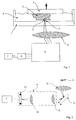
- FIG. 1 an apparatus for carrying out the method according to the invention
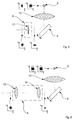
- Fig. 2 a unit for focus volume adjustment
- Fig. 3 a modified embodiment of the unit for adjusting the focal volume
- Fig. 4 a further modified embodiment of the unit for adjusting the focal volume
- Fig. 5 a further modified embodiment of the unit for adjusting the focal volume
- Fig. 6 a further modified embodiment of the unit for focus volume adjustment
- the Fig. 7 to 10 various building strategies using large and small volume elements.
- Fig. 1 It can be seen that an electromagnetic wave emitted by the laser 7 is guided through a unit for changing the focal point volume 8 and via a beam deflection unit 9 and focused by means of an optical imaging system 10 through a transparent bottom plate 1 in a photosensitive material 2.
- an optical imaging system 10 At the focal point 5 of the optical imaging system 10, there is a change in state of the photosensitive material 2, whereby the component 3 is constructed.
- the component 3 hangs on a building platform 4, which can be moved in the vertical direction. After the current layer has been fully exposed, the build platform 4 is raised and the next layer is exposed.
- Fig. 1 All elements in Fig. 1 are shown only symbolically and can be expanded arbitrarily and according to the knowledge of the skilled person, for example by using additional lens systems, screens, mirrors, filters or beam splitters.
- Fig. 2 schematically shows the unit 8 for changing the focal point volume.
- the unit comprises a diffractive optical element 11 which splits the incoming beam into two beams passing through a system of two lenses 12 and 13. The splitting of the beam takes place with the goal of creating two points next to each other in the focal plane. If both points overlap, you can also speak of a line.
- Fig. 3 shows a modified embodiment of the unit 8 for changing the focal point volume.
- the unit 8 comprises two spaced apart coaxial cylindrical lenses 14 and 15 which are traversed by the beam.
- the beam profile before entering the unit 8, in the plane shown in dashed lines, is circular.
- a compression in the direction of the y-axis can be observed. This results in the expansion point volume shown in the drawing at the focal point 5 in the x, z plane and in the y, z plane.
- Iris diaphragm 16 causes a reduction in the effective numerical aperture of the imaging system, which makes the focal point volume both longer and wider.
- the possibilities of changing the focal point volume shown are made using pulsed laser light having a wavelength in the range from 400 to 1600 nm, the pulse length being between 1 fs and 1 ns.
- Fig. 7 shows a component that has been constructed by a method in which only small focal point volumes 22 are solidified without adaptation of the volume.
- the high resolution results in a large number of points to be written and thus a high process time per shift.
- This building strategy is advantageous for small, high-resolution structures, where adaptation of the focal point volume would bring no advantage or throughput is not critical.
- the building process shown only a large focal point volume 32 is used without adaptation of the volume.
- the building strategy has a high throughput but low resolution.
- the focal point volume is controlled by the optical unit 8, wherein the area of the focal point volume is increased and the effective numerical aperture is adjusted to the desired layer thickness. This building strategy is advantageous for components that do not require high resolution, but where high throughput is required.
- the possible course of a construction process with two different focal point volumes is described in Fig. 9 shown.
- the structure 41 to be built is built up layer by layer alternately from fine 42 and coarse filling volumes 43. With the fine filling volume 42 those parts of the structure are exposed that can not be achieved with the coarse filling volume 43. It is advantageous first to write high-resolution parts with the small focal point volume 42 and then to fill the inner volume, since already built structures can distort the focus point.
- the adaptive focus-point volume enables the fabrication of both high-resolution and high-throughput devices. This building strategy is suitable for high resolution components with light surface roughness.
- the course of construction strategy in Fig. 10 is similar to the one in Fig. 9 shown construction strategy, except that now the surface of the component is built with an additional small focal point volume 54 and small layer thickness.
- the three focal point volumes are named as follows: the fine fill volume 52, the coarse fill volume 53 and the surface volume 54.
- the surface volume has the smallest volume and thus the highest resolution for good shape rendering of corners and edges.
- the fine fill volume 52 is equal to or greater than the surface volume 54 and fills gaps that can not be reached by the coarse fill volume 53.
- This building strategy is suitable for components that require excellent shape reproduction, surface quality and high throughput.
Landscapes
- Engineering & Computer Science (AREA)
- Chemical & Material Sciences (AREA)
- Materials Engineering (AREA)
- Physics & Mathematics (AREA)
- Manufacturing & Machinery (AREA)
- Optics & Photonics (AREA)
- Mechanical Engineering (AREA)
- Toxicology (AREA)
- Plasma & Fusion (AREA)
- Health & Medical Sciences (AREA)
- General Physics & Mathematics (AREA)
- Ceramic Engineering (AREA)
- Organic Chemistry (AREA)
- Structural Engineering (AREA)
- Chemical Kinetics & Catalysis (AREA)
- Exposure And Positioning Against Photoresist Photosensitive Materials (AREA)
Abstract
Description
- Die Erfindung betrifft ein Verfahren zur lithographiebasierten generativen Fertigung von dreidimensionalen Bauteilen, bei dem durch Einwirkung elektromagnetischer Strahlung verfestigbares Material in einer Wanne vorliegt, eine Bauplattform in Abstand vom Wannenboden positioniert wird, zwischen der Bauplattform und dem Wannenboden befindliches Material ortsselektiv mit Hilfe einer Bestrahlungseinheit bestrahlt wird, wobei die elektromagnetische Strahlung von unten durch einen für die Strahlung zumindest bereichsweise durchlässigen Wannenboden in das Material eingebracht und nacheinander auf Fokuspunkte innerhalb des Materials fokussiert wird, wodurch jeweils ein am Fokuspunkt befindliches Volumenelement des Materials verfestigt wird, wobei die Verfestigung mittels Multiphotonenabsorption erfolgt.
- Die Erfindung betrifft weiters eine Vorrichtung zur lithographiebasierten generativen Fertigung von dreidimensionalen Bauteilen, die insbesondere zur Durchführung eines solchen Verfahrens geeignet ist.
- Lithographiebasierte generative Fertigung (L-GF, z.B. Stereolithographie) wird traditionell hauptsächlich für die Herstellung von Prototypen und Funktionsmustern verwendet. Durch technische Weiterentwicklungen rücken zusehends echte Produktionsanwendungen in den Fokus (z.B. transparente Zahnspangen, Hörgeräteschalen). Im Zuge dieser Entwicklungen wird es immer wichtiger, dass möglichst große Teile herstellbar sind. Ebenso von größer Bedeutung ist der erzielbare Durchsatz. Lithographiebasierte Techniken (z.B. Stereolithographie) bieten gegenüber anderen generativen Verfahren vor allem Vorteile hinsichtlich Auflösung, Präzision und Oberflächenqualität.
- Derzeit verfügbare L-GF Verfahren belichten entweder von oben auf eine mit photosensitivem Material gefüllte Wanne, wie in der
WO 93/08506 A1 WO 01/40866 A2 - Auch bei der Belichtung von unten gibt es Schwierigkeiten: Das flüssige photosensitive Material befindet sich in diesem Fall zwischen der transparenten Wanne und der Bauplattform, die schichtweise nach oben verschoben wird. Trotz der Antihaftbeschichtung der Wanne haftet das Bauteil während des Bauvorgangs unerwünschterweise an der Wanne an. Beim Anheben der Bauplattform können so große Abzugskräfte entstehen, was insbesondere bei der Fertigung größerer Bauteile zu Problemen führt. Es gibt dazu zwar neue Ansätze (z.B.
US 2014/361463 A1 ), die über Sauerstoffeinbringung eine Inhibierungsschicht zwischen Wanne und Bauteil erzeugen und so eine Anhaftung reduzieren. Allerdings besteht dann das Problem, dass das nachfließende Material in einen sehr dünnen Spalt fließen muss, was bei dickwandigeren Bauteilen oder hochviskosen Materialien problematisch ist. - Bei allen oben genannten Verfahren besteht zudem das Problem, dass bei Erhöhung der Auflösung die Bauzeiten sehr rasch ansteigen.
- In der
DE 10111422 A1 wurde ein Verfahren vorgeschlagen, bei dem die Verfestigung des flüssigen photosensitiven Materials durch Multiphotonenabsorption vorgenommen wird. Dazu strahlt man mit einem fokussierten Laserstrahl in das Bad des photosensitiven Materials ein, wobei die Bestrahlungsbedingungen für einen die Verfestigung auslösenden Mehrphotonenabsorptionsprozess nur in unmittelbarer Umgebung des Fokus erfüllt sind, sodass man den Fokus des Strahls nach Maßgabe der Geometriedaten des herzustellenden Formkörpers innerhalb des Badvolumens zu den zu verfestigenden Stellen führt. Die Bestrahlung des Materialbades erfolgt bei dem Verfahren gemäß der
DE 10111422 A1 von oben, wobei die Strahlungsintensität so gewählt wird, dass die Flüssigkeit für die verwendete Strahlung oberhalb des Fokuspunktes im Wesentlichen transparent ist, sodass ein direktes Polymerisieren des Badmaterials ortsselektiv innerhalb des Badvolumens, d.h. auch weit unterhalb der Badoberfläche stattfindet. - Bei der Veränderung der Lage des Fokuspunkts entlang der optischen Achse des verwendeten optischen Abbildungssystems ergeben sich jedoch Abbildungsfehler, die mit zunehmendem Anteil von Material im optischen Pfad mit nicht optimal abgestimmtem Brechungsindex zunehmen. Dies ist besonders bei Verfahren von Nachteil, bei denen sehr feine Strukturen hergestellt werden und daher eine hohe Auflösung des Abbildungssystems erforderlich ist. Um die hohe Auflösung des optischen Abbildungssystems zu gewährleisten, muss der Brechungsindex des photosensitiven Materials auf das optische Abbildungssystem, oder umgekehrt, abgestimmt sein. Sollte das nicht der Fall sein, oder das Material seine Eigenschaften, zum Beispiel durch Änderung des Wassergehalts, während des Bauprozesses ändern, würde die erzielbare Auflösung der gebauten Strukturen abnehmen.
- Für die Multiphotonenabsorptions-Strukturierung mit hoher Auflösung im Nanometerbereich wurde in der
DE 102011012484 A1 daher ein Verfahren vorgeschlagen, bei dem das Objektiv des optischen Abbildungssystems in das photosensitive Material eintaucht. Dadurch sind größere Bauteilhöhen mit hoher Auflösung realisierbar, die optische Abbildungseinheit ist aber im ständigen Kontakt mit dem photosensitiven Harz, was bei ungewollter Materialumwandlung, zum Beispiel durch Streulicht oder Umgebungslicht, zu einer Beschädigung der Optik führen kann. - In der
EP 2905121 A1 ist ein Verfahren beschrieben, bei dem die Verfestigung des photosensitiven Materials ebenfalls mittels Multiphotonenabsorption stattfindet und die Belichtung des Bades von unten durch einen transparenten Boden der Materialwanne erfolgt. Die Fokussierung erfolgt auf Fokuspunkte, die in fixem Abstand vom Wannenboden liegen, wobei die Bauplattform mit fortschreitendem Arbeitsfortschritt in Höhenrichtung aus dem Bad gezogen wird, sodass Bauteile mit großer Höhe hergestellt werden können. - Ein Großteil der bisherigen Verfahren im Bereich der Multiphotonenabsorptions-Strukturierung zielt darauf ab, Strukturen mit sehr hoher Auflösung zu schreiben. Durch hochauflösende optische Abbildungssysteme, meist aus der Mikroskopie, werden dabei Auflösungen bis zu 50nm erzielt. Die hohe Auflösung bedingt kleine Fokuspunktvolumen, die durch Verwendung von optischen Abbildungssystemen mit hoher Vergrößerung und hoher numerischer Apertur erreicht werden. Durch die hohe numerische Apertur ist auch ein annähernd kugelförmiges Fokuspunktvolumen erzielbar (typischerweise kleiner als 1x1x1µm3). Bedingt durch das kleine Fokuspunktvolumen ist der Durchsatz solcher Anlagen allerdings sehr gering, da z.B. für ein Volumen von 1mm3 insgesamt mehr als 109 Punkte belichtet werden müssen. Dies führt zu sehr langen Bauzeiten, was der Hauptgrund für den geringen industriellen Einsatz von Multiphotonenabsorptions-Verfahren ist.
- Die vorliegende Erfindung zielt daher darauf ab, ein Verfahren und eine Vorrichtung der eingangs genannten Art dahingehend zu verbessern, dass der Bauteiledurchsatz erhöht wird ohne die Möglichkeit einer hohen Strukturauflösung zu verlieren.
- Zur Lösung dieser Aufgabe besteht die Erfindung bei einem Verfahren der eingangs genannten Art darin, dass das Volumen des Fokuspunkts während des Verfahrens zumindest einmal variiert wird, sodass der Bauteil aus verfestigten Volumenelementen unterschiedlichen Volumens aufgebaut wird. Durch das variable Volumen des Fokuspunktes sind (bei kleinem Fokuspunktvolumen) hohe Auflösungen möglich. Gleichzeitig ist (bei großem Fokuspunktvolumen) eine hohe Schreibgeschwindigkeit (gemessen in mm3/h) erzielbar. Die Erfindung kombiniert also hohe Auflösung mit großem Durchsatz. Die Variation des Fokuspunktvolumens kann dabei zum Beispiel so genutzt werden, dass im Inneren des aufzubauenden Bauteils ein großes Fokuspunktvolumen verwendet wird, um den Durchsatz zu erhöhen, und an der Oberfläche des Bauteils ein kleineres Fokuspunktvolumen verwendet wird, um die Bauteiloberfläche mit hoher Auflösung auszubilden. Eine Vergrößerung des Fokuspunktvolumens ermöglicht einen höheren Strukturierungsdurchsatz, da das in einem Belichtungsvorgang verfestigte Materialvolumen vergrößert wird. Um bei hohem Durchsatz eine hohe Auflösung beizubehalten, können kleine Fokuspunktvolumina für feinere Strukturen und Oberflächen, und größere Fokuspunktvolumina für grobe Strukturen und/oder zum Füllen von Innenräumen verwendet werden.
- Bei einer bevorzugten Verfahrensweise erfolgt die Variation des Fokusvolumens derart, dass das größte Fokuspunktvolumen während der Fertigung eines Bauteils größer 1µm3, bevorzugt größer 100µm3, insbesondere größer 10.000µm3 ist.
- Das Prinzip der Multiphotonenabsorption wird im Rahmen der Erfindung genutzt, um im photosensitiven Materialbad einen photochemischen Vorgang zu initiieren. Als Folge der photochemischen Reaktion kommt es zur Veränderung des Materials in mindestens einen anderen Zustand, wobei es typischerweise zu einer Photopolymerisation kommt. Die Belichtung erfolgt dabei von unten durch einen für die elektromagnetische Strahlung transparenten Wannenboden. Das Prinzip der Multiphotonenabsorption beruht darauf, dass der genannte photochemische Vorgang nur in jenen Bereichen des Strahlengangs stattfindet, in denen eine für die Multiphotonenabsorption ausreichende Photonendichte vorliegt. Die höchste Photonendichte tritt im Brennpunkt des optischen Abbildungssystems auf, sodass die Multiphotonenabsorption mit ausreichender Wahrscheinlichkeit nur im Fokuspunkt auftritt. Außerhalb des Brennpunktes ist die Photonendichte geringer, sodass die Wahrscheinlichkeit der Multiphotonenabsorption außerhalb des Brennpunktes zu gering ist, um eine unumkehrbare Veränderung des Materials durch eine photochemische Reaktion zu bewirken. Die elektromagnetische Strahlung kann in der verwendeten Wellenlänge weitestgehend ungehindert das Material passieren und nur im Fokuspunkt kommt es zu einer Interaktion zwischen photosensitivem Material und elektromagnetischer Strahlung. Das Prinzip der Multiphotonenabsorption ist beispielsweise in Zipfel et al, "Nonlinear magic: multiphoton microscopy in the biosciences", NATURE BIOTECHNOLOGY VOLUME 21 NUMBER 11 NOVEMBER 2003, beschrieben.
- Als Quelle für die elektromagnetische Strahlung kann es sich vorzugsweise um einen kollimierten Laserstrahl handeln. Der Laser kann sowohl eine oder mehrere, feste oder variable Wellenlängen emittieren. Insbesondere handelt es sich um einen kontinuierlichen oder gepulsten Laser mit Pulslängen im Nanosekunden-, Pikosekunden- oder Femtosekunden-Bereich. Ein gepulster Femtosekundenlaser bietet dabei den Vorteil, dass eine geringere mittlere Leistung für die Multiphotonenabsorption benötigt wird.
- Unter photosensitivem Material wird jedes unter Baubedingungen fließfähige Material verstanden, das durch Multiphotonenabsorption im Fokuspunktvolumen in einen zweiten Zustand übergeht - beispielsweise durch Polymerisation. Die Materialveränderung muss sich dabei auf das Fokuspunktvolumen und dessen direkte Umgebung begrenzen. Die Veränderung der Substanzeigenschaften kann dauerhaft sein und beispielsweise in einer Veränderung von einem flüssigen in einen festen Zustand bestehen, kann jedoch auch nur vorübergehend sein. Auch eine dauerhafte Veränderung kann im Übrigen reversibel oder nicht reversibel sein. Die Änderung der Materialeigenschaften muss nicht zwingend vollständig von einem in den anderen Zustand übergehen, sondern kann auch als Mischform beider Zustände vorliegen.
- Die Leistung der elektromagnetischen Strahlung und die Belichtungsdauer beeinflussen die Qualität des erzeugten Bauteils. Durch Anpassung der Strahlungsleistung und/oder der Belichtungsdauer kann das Volumen des Fokuspunktes in einem engen Bereich variiert werden. Bei zu hohen Strahlungsleistungen treten zusätzliche Prozesse auf, die zur Beschädigung des Bauteils führen können. Ist die Strahlungsleistung zu gering, kann sich keine dauerhafte Materialeigenschaftsänderung einstellen. Für jedes photosensitive Material gibt es daher typische Bauprozessparameter, die mit guten Bauteileigenschaften verbunden sind.
- Die erfindungsgemäße Variation des Fokuspunktvolumens beruht hierbei jedoch nicht auf einer Änderung der Intensität der verwendeten elektromagnetischen Strahlung. Vielmehr wird bei der für den Bauprozess gewählten (optimalen) Strahlungsintensität gearbeitet, die während des Bauteilaufbaus unverändert gelassen wird. Das erfindungsgemäße Verfahren wird daher bevorzugt so durchgeführt, dass die Änderung des Fokuspunktvolumens bei gleichbleibender Strahlungsintensität vorgenommen wird.
- Als Fokuspunktvolumen wird daher jenes Volumen eines belichteten Punktes nach dem Aufbereitungsschritt bei den typischen Bauprozessparametern verstanden. Unter der erfindungsgemäßen Änderung des Fokuspunktvolumens wird eine Veränderung der räumlichen Intensitätsverteilung im Fokuspunkt verstanden. Hierbei kann die räumliche Intensitätsverteilung des Fokuspunktes sowohl in eine oder mehrere Richtungen verändert werden. So kann zum Beispiel durch Reduktion der effektiven numerischen Apertur des optischen Abbildungssystems die Intensitätsverteilung in alle drei Raumrichtungen vergrößert werden. Bei der Verwendung eines diffraktiven optischen Elementes kann der Fokus in eine Linie oder Fläche verändert, oder die Anzahl der Fokuspunkte erhöht werden.
- Eine bevorzugte Verfahrensweise der Erfindung sieht vor, dass die Änderung des Fokuspunktvolumens mittels einer Einheit bestehend aus wenigstens einem im Strahlengang zwischen der Quelle der elektromagnetischen Strahlung und einem auf den Fokuspunkt fokussierenden optischen Abbildungssystem angeordneten optischen Element vorgenommen wird.
- Die Änderung des Fokuspunktvolumens mittels des wenigstens einen optischen Elements kann auf verschiedenste Weise erfolgen, wobei die nachfolgend angeführten Möglichkeiten auch miteinander kombiniert werden können.
- Bevorzugt ist vorgesehen, dass die Änderung des Fokuspunktvolumens durch Variation der effektiven numerischen Apertur des optischen Abbildungssystems erfolgt. Unter numerischer Apertur des optischen Abbildungssystems werden dessen nominelle Eigenschaften unter optimalen Bedingungen mit der kleinsten möglichen Fokuspunktgröße verstanden. Kommt es durch Veränderung der optischen Parameter vor dem optischen Abbildungssystem zu größeren Fokuspunktvolumen, spricht man von der effektiven numerischen Apertur des Abbildungssystems.
- Bevorzugt kann auch vorgesehen sein, dass die Änderung des Fokuspunktvolumens durch Variation des Strahldurchmessers entlang des Strahlengangs erfolgt.
- Das Verfahren kann bevorzugt auch so durchgeführt werden, dass die Variation des Strahldurchmessers mittels einer insbesondere variablen Aufweitoptik oder einer verstellbaren Blende erfolgt. Unter einer Aufweitoptik wird ein optisches System verstanden, mit dem der Strahldurchmesser vergrößert oder verkleinert wird. Der Strahldurchmesser bestimmt zusammen mit der Brennweite des optischen Abbildungssystems das Fokuspunktvolumen. Bei konstanter Brennweite führt eine Veränderung des Strahldurchmessers daher zu einer Änderung der effektiven numerischen Apertur und damit zu einer Änderung des Fokuspunktvolumens. Die Aufweitoptik kann sowohl mit konstanter oder variabler Aufweitung ausgeführt sein. Im Falle einer variablen Aufweitung kann die Aufweitoptik zur Veränderung des Fokuspunktvolumens eingesetzt werden.
- Eine Veränderung des Strahldurchmessers kann auch mit Hilfe einer verstellbaren Blende vorgenommen werden, wobei eine Verkleinerung des Strahldurchmessers beispielsweise zu einer Reduzierung der effektiven numerischen Apertur führt, wodurch sich Durchmesser und Länge des Fokuspunktvolumens erhöhen. Die Blende kann als eindimensionale Schlitzblende, als zweidimensionale Irisblende oder jegliche andere Blendenform ausgeführt werden.
- Bevorzugt wird das wenigstens eine optische Element von einem diffraktiven optischen Element und/oder einer optischen Linse gebildet. Eine mögliche Anwendung eines diffraktiven optischen Elements liegt darin, aus dem eintreffenden Strahl mehrere Strahlen, welche sich im Austrittswinkel unterscheiden, zu formen. Die einzelnen Strahlen werden durch das optische Abbildungssystem auf die Fokusebene abgebildet, wobei die einzelnen Fokuspunkte der einzelnen Strahlen unterschiedliche Punkte in der Fokusebene darstellen. Je nach verwendetem diffraktiven optischen Element können hier ein oder mehrere Fokuspunkte abgebildet werden. Die Fokuspunkte können auch so nahe zueinander liegen, dass die einzelnen Punkte ineinander übergehen. In diesen Fall entstehen Linien oder Flächen. Das diffraktive optische Element kann statisch oder dynamisch sein. Bei dynamischen diffraktiven optischen Elementen spricht man von einem "spatial light modulator".
- Die Einheit zur Veränderung des Fokuspunktvolumens kann auch ein optisches System zur Strahlformung enthalten. Ein solches optisches System kann aus zwei Zylinderlinsen mit variablem Abstand zur gezielten Kontrolle des Astigmatismus im optischen Abbildungssystem bestehen. Durch Variation des Linsenabstands kann eine Dimension des Fokuspunktvolumens gezielt beeinflusst werden.
- Weiters kann die Einheit zur Veränderung des Fokuspunktvolumens auch ein oder mehrere schnell bewegte Strahlablenksysteme beinhalten, welche den Strahl in einem bekannten Winkel zu den anderen Ablenksystemen führt. In bevorzugter Weise stehen zwei Ablenksysteme im rechten Winkel zueinander. Während das eine Ablenksystem den Strahl durch das photosensitive Material führt, verbreitert das zweite das umgewandelte Materialvolumen durch eine schnelle Bewegung des Strahls orthogonal zur Strahlführungsrichtung.
- Mit den genannten Maßnahmen zur Veränderung des Fokuspunktvolumens kann die Änderung des Fokuspunktvolumens in wenigstens eine, vorzugsweise in drei, senkrecht zueinander stehenden Raumrichtungen erfolgen.
- Im Rahmen der beschriebenen Maßnahmen zur Veränderung des Fokuspunktvolumens kann die numerische Apertur des optischen Abbildungssystems klein gewählt werden, wobei die numerische Apertur vorzugsweise kleiner 0,8, vorzugsweise kleiner 0,2 gewählt ist.
- Wie bereits erwähnt wird der Bauteil erfindungsgemäß so aufgebaut, dass die elektromagnetische Strahlung von unten durch einen für die Strahlung zumindest bereichsweise durchlässigen Wannenboden in das Material eingebracht und nacheinander auf eine Vielzahl von Fokuspunkten innerhalb des Materials fokussiert wird. Bevorzugt wird hierbei so vorgegangen, dass die elektromagnetische Strahlung mittels einer vorzugsweise vor dem optischen Abbildungssystem angeordneten Ablenkeinheit abgelenkt wird, um den Fokuspunkt in einer zum Wannenboden im Wesentlichen parallelen Ebene (X- und Y-Richtung) zu verstellen. Die Verstellung erfolgt jedes Mal, nachdem ein Volumenelement des Materials verfestigt wurde. Für die Ablenkung des Strahls können dabei beliebige Strahlablenkeinheiten eingesetzt werden, welche aus dem Stand der Technik bekannt sind. Beispielsweise kann eine separate Strahlablenkeinrichtung für eine Strahlablenkung in X-Richtung und eine Strahlablenkeinrichtung für eine Ablenkung in Y-Richtung vorgesehen werden. Zusätzlich kann die Strahlablenkungseinheit mit einem Positioniersystem kombiniert oder dadurch teilweise ersetzt werden, welches das Bildfeld des Abbildungssystems bewegt, um die Herstellung von Bauteilen mit größerer Erstreckung in X-und Y-Richtung zu ermöglichen. Dabei ist es unerheblich, ob das optische Abbildungssystem oder das Bauteil bewegt wird.
- Eine bevorzugte Verfahrensweise sieht weiters vor, dass die Bauplattform mit fortschreitendem Baufortschritt schrittweise angehoben wird. Der Aufbau des Bauteils kann dabei z.B. schichtweise erfolgen. Es werden zuerst alle Volumenelemente in einer Ebene bzw. Schicht hergestellt, worauf die Bauplattform zur Ausbildung der nächsten Schicht angehoben wird. Dazu wird eine in vertikaler Richtung (Z-Richtung) verstellbare Bauplattform in dem photosensitiven Material angeordnet. An dieser Bauplattform haftet die erste durch multiphotoneninduzierte Materialumwandlung erzeugte Schicht des zukünftigen Bauteils an. Die zweite Schicht haftet an der ersten Schicht an und jede weitere Schicht haftet an der jeweils vorangehenden Schicht an, sodass das Bauteil durch schichtweisen Aufbau aus der Wanne herauswächst.
- Besonders bevorzugt wird der Fokuspunkt hierbei im Abstand vom Wannenboden angeordnet. Typischerweise beträgt der Abstand des Fokuspunktes vom Wannenboden zwischen 20µm und 2mm. Auf Grund des Abstands zwischen Polymerisationszone und dem Wannenboden kann es zu keiner unerwünschten Anhaftung des umgewandelten Materials an der Wanne kommen. Zusätzlich kann frisches Material leichter zwischen Bauteil und Wanne nachfließen, um als Ausgangsmaterial für die folgenden Schichten zur Verfügung zu stehen. Da es zu keiner Anhaftung des Bauteils am Wannenboden kommt, sind keine Abzugskräfte beim Anheben der Bauplattform zu erwarten. Basis dieses Effekts ist die Tatsache, dass der photochemische Vorgang bei der Multiphotonenabsorption wie bereits erwähnt nur in einem gut definierten Fokusvolumen stattfinden kann. Wenn der Abstand zwischen Wannenboden und Bauschicht relativ groß gewählt wird, kann während des Bauprozesses Material in den Spalt zwischen Wannenboden und Bauteil nachfließen, wodurch ein weitestgehend kontinuierlicher Prozess ermöglicht wird.
- Bei dem beschriebenen schichtweisen Aufbau des Bauteils kann der Normalabstand der Fokuspunkte vom Wannenboden konstant gehalten werden, weil die Bewegung des Bauteils in vertikaler Richtung durch die bewegliche Bauplattform realisiert wird. Dadurch bleiben die optischen Randbedingungen während des ganzen Bauprozesses konstant. Damit wird gegenüber dem Stand der Technik, bei dem der Fokus in vertikaler Richtung bewegt wird, der Vorteil erreicht, dass die elektromagnetische Strahlung nicht unterschiedlich tief ins photosensitive Material fokussiert werden muss, was zu tiefenabhängigen Variationen der Fokusqualität führen würde. Der konstant gehaltene Normalabstand wird vorzugsweise zwischen dem Wannenboden und dem Mittelpunkt des Fokuspunktvolumens gemessen. Alternativ kann der konstant gehaltene Normalabstand zwischen dem Wannenboden und der unteren Berandung des Fokuspunktvolumens gemessen werden.
- Die erfindungsgemäße Änderung des Fokuspunktvolumens kann hierbei auch innerhalb ein und derselben Schicht erfolgen, sodass eine Schicht aus Volumenelementen unterschiedlichen Volumens zusammengesetzt wird. Es kann aber auch so vorgegangen werden, dass sich eine Schicht aus lauter gleich großen Volumenelementen zusammensetzt und dass ein geändertes Fokuspunktvolumen für die nächste Schicht angewendet wird.
- Als optisches Abbildungssystem, das die elektromagnetische Strahlung auf den jeweiligen Fokuspunkt fokussiert, kann jegliches, nach dem Stand der Technik bekanntes, optisches System mit einer beliebigen Anzahl optischer Elemente zur Fokussierung eingesetzt werden. Die optische Abbildungseinheit kann vor oder nach der Strahlablenkungseinheit eingesetzt werden. Beispielsweise kann eine F-Theta Optik nach dem Strahlablenksystem mit einer moderaten numerischen Apertur von < 0.2 verwendet werden.
- Zwischen der Strahlablenkungseinheit und der Fokussieroptik des optischen Abbildungssystems kann eine zusätzliche optische Strahlaufweitung oder -reduktion eingefügt sein. Dieses zusätzliche optische System kann die effektive numerische Apertur durch Änderung des Strahldurchmessers bei gleichbleibender Brennweite der optischen Abbildungseinheit vergrößern oder verkleinern. Jegliche Anpassungen nach dem Strahlablenkungssystem wirken sich jedoch auf die Strahlablenkgeschwindigkeit aus.
- Ein weiterer Aspekt der Erfindung betrifft eine Vorrichtung zur lithographiebasierten generativen Fertigung von dreidimensionalen Bauteilen, insbesondere zur Durchführung eines Verfahrens nach dem ersten Aspekt der Erfindung. Die Vorrichtung umfasst eine Quelle elektromagnetischer Strahlung, eine Wanne mit einem zumindest bereichsweise für die Strahlung durchlässigen Boden, in die verfestigbares Material einfüllbar ist, eine Bauplattform, die in einstellbarer Höhe über dem Wannenboden gehalten ist, und eine Bestrahlungseinheit, die zur ortsselektiven Bestrahlung von zwischen der Bauplattform und dem Wannenboden befindlichen Material von unten durch den Wannenboden ansteuerbar ist, wobei die Bestrahlungseinheit ein optisches Abbildungssystem umfasst, um die Strahlung nacheinander auf Fokuspunkte innerhalb des Materials zu fokussieren, wodurch jeweils ein am Fokuspunkt befindliches Volumenelement des Materials mittels Multiphotonenabsorption verfestigbar ist. Die Vorrichtung ist dadurch gekennzeichnet, dass die Bestrahlungseinheit wenigstens ein im Strahlengang zwischen der Quelle der elektromagnetischen Strahlung und dem optischen Abbildungssystem angeordnetes optisches Element umfasst, welches zur Änderung des Volumens des Fokuspunkts ausgebildet ist.
- Bevorzugt kann das wenigstens eine optische Element zur Veränderung der effektiven numerischen Apertur des Abbildungssystems verwendet werden.
- Bevorzugt ist vorgesehen, dass das wenigstens eine optische Element zur Variation des Strahldurchmessers entlang des Strahlengangs vorhanden ist.
- Bevorzugt ist vorgesehen, dass das wenigstens eine optische Element von einer variablen Aufweitoptik oder einer verstellbaren Blende gebildet ist.
- Bevorzugt kann auch vorgesehen sein, dass das wenigstens eine optische Element von einem diffraktiven optischen Element und/oder einer optischen Linse gebildet wird.
- Insbesondere kann das wenigstens eine optische Element ein Strahlformungssystem umfassen, das z.B. zwei in variablem Abstand zueinander gehaltene Zylinderlinsen umfasst.
- Bevorzugt umfasst die Bestrahlungseinheit eine vorzugsweise vor dem optischen Abbildungssystem angeordnete Ablenkeinheit, um den Fokuspunkt in einer zum Wannenboden im Wesentlichen parallelen Ebene zu verstellen.
- Mit Vorteil ist eine mit der Bestrahlungseinheit zusammenwirkende Steuereinheit dazu vorbereitet, in aufeinanderfolgenden Bestrahlungsschritten in einer Schicht liegende Volumenelemente auf der Bauplattform zur Ausbildung einer Schicht mit vorgegebener Geometrie durch Steuerung der Bestrahlungseinheit zu verfestigen und nach den Bestrahlungsschritten für die Schicht die Relativposition der Bauplattform zum Wannenboden anzupassen, um so sukzessive den Bauteil in der gewünschten Form aufzubauen.
- Die Erfindung wird nachfolgend anhand von in der Zeichnung schematisch dargestellten Ausführungsbeispielen näher erläutert. In dieser zeigen
Fig. 1 eine Vorrichtung zur Durchführung des erfindungsgemäße Verfahrens,Fig. 2 eine Einheit zur Fokusvolumenanpassung,Fig. 3 eine abgewandelte Ausbildung der Einheit zur Fokusvolumenanpassung,Fig. 4 eine weitere abgewandelte Ausbildung der Einheit zur Fokusvolumenanpassung,Fig. 5 eine weitere abgewandelte Ausbildung der Einheit zur Fokusvolumenanpassung,Fig. 6 eine weitere abgewandelte Ausbildung der Einheit zur Fokusvolumenanpassung und dieFig. 7 bis 10 verschiedene Baustrategien unter Verwendung von großen und kleinen Volumenelementen. - In
Fig. 1 ist ersichtlich, dass eine vom Laser 7 emittierte elektromagnetische Welle durch eine Einheit zur Veränderung des Fokuspunktvolumens 8 und über eine Strahlablenkeinheit 9 geführt und mittels eines optischen Abbildungssystems 10 durch eine transparente Bodenplatte 1 in ein photosensitives Material 2 fokussiert wird. Im Brennpunkt 5 des optischen Abbildungssystems 10 kommt es zur Zustandsänderung des photosensitiven Materials 2, womit das Bauteil 3 aufgebaut wird. Das Bauteil 3 hängt an einer Bauplattform 4, die in vertikaler Richtung bewegt werden kann. Nachdem die aktuelle Schicht fertig belichtet wurde, wird die Bauplattform 4 angehoben und die nächste Schicht wird belichtet. Durch Verwendung eines Lasers 7 mit hoher Spitzenleistung ist der Einsatz von Multiphotonenabsorption möglich, sodass die Zustandsänderung des Materials nur im Fokus 5 stattfindet, nicht aber in der optisch "toten" Zone 6 zwischen dem Wannenboden 1 und der Bauplattform bzw. dem bereits gebildeten Bauteil. Somit kann es zu keiner Anhaftung des Bauteils an der transparenten Bodenplatte 1 kommen. - Sämtliche Elemente in
Fig. 1 sind lediglich symbolisch dargestellt und können beliebig und entsprechend dem Wissen des Fachmanns erweitert werden, beispielsweise durch Einsatz zusätzlicher Linsensysteme, Blenden, Spiegel, Filter oder Strahlteiler. -
Fig. 2 zeigt schematisch die Einheit 8 zur Veränderung des Fokuspunktvolumens. Die Einheit umfasst ein diffraktives optisches Element 11, welches den eintreffenden Strahl in zwei Strahlen aufspaltet, die ein System aus zwei Linsen 12 und 13 durchlaufen. Die Aufspaltung des Strahls erfolgt mit dem Ziel, zwei Punkte nebeneinander in der Fokusebene zu erzeugen. Überlappen einander beide Punkten, kann man auch von einer Linie sprechen. -
Fig. 3 zeigt eine abgewandelte Ausbildung der Einheit 8 zur Veränderung des Fokuspunktvolumens. Die Einheit 8 umfasst zwei voneinander beabstandete koaxiale Zylinderlinsen 14 und 15, welche von dem Strahl durchlaufen werden. Das Strahlprofil vor dem Eintritt in die Einheit 8, und zwar in der strichliert dargestellten Ebene, ist kreisrund. Am Austritt aus der Einheit 8 ist eine Komprimierung in Richtung der y-Achse zu beobachten. Daraus ergibt sich am Fokuspunkt 5 in der x,z-Ebene und in der y,z-Ebene die in der Zeichnung dargestellt Ausdehnung des Fokuspunktvolumens.
Durch Einstellung des Abstands zwischen den Zylinderlinsen 14 und 15 ändert sich das Volumen des Gesamt-Fokuspunkts 5. - Ein ähnlicher Effekt ergibt sich bei Verwendung einer Schlitzblende 17, wie dies in der Ausbildung gemäß
Fig. 5 gezeigt ist, wobei hier jedoch Intensitätsverluste durch das Abschneiden des Strahls entstehen. - Bei der Ausbildung gemäß
Fig. 4 bewirkt eine Irisblende 16 eine Reduzierung der effektiven numerischen Apertur des Abbildungssystems, wodurch das Fokuspunktvolumen sowohl länger als auch breiter wird. - Der bei der Ausbildung gemäß
Fig. 6 gezeigte Expander aus den Linsen 18 und 19 hat den gleichen Effekt wie die Irisblende 16, vermeidet aber Intensitätsverluste, indem der Strahldurchmesser verkleinert wird ohne den Strahl abzuschneiden. - Die in den
Fig. 2 bis 6 gezeigten Möglichkeiten zur Änderung des Fokuspunktvolumens erfolgen insbesondere unter Verwendung von gepulstem Laserlicht mit einer Wellenlänge im Bereich von 400 bis 1600nm, wobei die Pulslänge zwischen 1fs und 1ns beträgt. -
Fig. 7 zeigt einen Bauteil, der mittels eines Verfahrens aufgebaut wurde, bei dem ausschließlich kleine Fokuspunktvolumina 22 ohne Adaption des Volumens verfestigt werden. Durch die hohe Auflösung ergibt sich eine große Anzahl zu schreibender Punkte und damit eine hohe Prozesszeit pro Schicht. Diese Baustrategie ist vorteilhaft für kleine, hochaufgelöste Strukturen, wo eine Adaption des Fokuspunktvolumens keinen Vorteil bringen würde oder der Durchsatz nicht entscheidend ist. - Für den in
Fig. 8 dargestellten Bauprozess wird nur ein großes Fokuspunktvolumen 32 verwendet ohne Adaption des Volumens. Die Baustrategie hat einen hohen Durchsatz, aber niedrige Auflösung. Das Fokuspunktvolumen wird durch die optische Einheit 8 kontrolliert, wobei die Fläche des Fokuspunktvolumens vergrößert und die effektive numerische Apertur auf die gewünschte Schichtdicke angepasst wird. Diese Baustrategie ist vorteilhaft für Bauteile, die keine hohe Auflösung benötigen, bei denen aber hoher Durchsatz gefordert wird. - Der mögliche Ablauf eines Bauprozesses mit zwei unterschiedlichen Fokuspunktvolumina wird in
Fig. 9 gezeigt. Durch Adaption des Fokuspunktvolumens während des Bauprozesses durch die optische Einheit 8 reduziert sich die Prozesszeit pro Schicht. Die zu bauende Struktur 41 wird Schicht für Schicht abwechselnd aus feinen 42 und groben Füllvolumina 43 aufgebaut. Mit dem feinen Füllvolumina 42 werden jene Teile der Struktur belichtet, die nicht mit dem groben Füllvolumen 43 erreicht werden können. Es ist von Vorteil zuerst hochaufgelöste Teile mit dem kleinen Fokuspunktvolumen 42 zu schreiben und danach das innere Volumen zu füllen, da es durch bereits gebaute Strukturen zur Verzerrung des Fokuspunkts kommen kann. Das adaptive Fokuspunktvolumen ermöglicht die Herstellung von Bauteilen mit sowohl hoher Auflösung als auch hohem Durchsatz. Diese Baustrategie eignet sich für Bauteile mit hoher Auflösung mit leichter Oberflächenrauigkeit. - Der Ablauf von Baustrategie in
Fig. 10 ist ähnlich der inFig. 9 dargestellten Baustrategie, außer dass nun die Oberfläche des Bauteils mit einem zusätzlichen kleinen Fokuspunktvolumen 54 und kleiner Schichtdicke gebaut wird. Die drei Fokuspunktvolumina werden folgend benannt: das feine Füllvolumen 52, das grobe Füllvolumen 53 und das Oberflächenvolumen 54. Das Oberflächenvolumen besitzt das kleinste Volumen und damit die höchste Auflösung für gute Formwiedergabe von Ecken und Kanten. Das feine Füllvolumen 52 ist gleich oder größer dem Oberflächenvolumen 54 und füllt Lücken, die durch das grobe Füllvolumen 53 nicht erreicht werden können. Diese Baustrategie eignet sich für Bauteile, bei denen eine ausgezeichnete Formwiedergabe, Oberflächenqualität und hoher Durchsatz gefordert werden.
Claims (25)
- Verfahren zur lithographiebasierten generativen Fertigung von dreidimensionalen Bauteilen, bei dem durch Einwirkung elektromagnetischer Strahlung verfestigbares Material in einer Wanne vorliegt, eine Bauplattform in Abstand vom Wannenboden positioniert wird, zwischen der Bauplattform und dem Wannenboden befindliches Material ortsselektiv mit Hilfe einer Bestrahlungseinheit bestrahlt wird, wobei die elektromagnetische Strahlung von unten durch einen für die Strahlung zumindest bereichsweise durchlässigen Wannenboden in das Material eingebracht und nacheinander auf Fokuspunkte innerhalb des Materials fokussiert wird, wodurch jeweils ein am Fokuspunkt befindliches Volumenelement des Materials verfestigt wird, wobei die Verfestigung mittels Multiphotonenabsorption erfolgt, dadurch gekennzeichnet, dass das Volumen des Fokuspunkts während des Verfahrens zumindest einmal variiert wird, sodass der Bauteil aus verfestigten Volumenelementen unterschiedlichen Volumens aufgebaut wird.
- Verfahren nach Anspruch 1, dadurch gekennzeichnet, dass die Änderung des Fokuspunktvolumens mittels wenigstens eines im Strahlengang zwischen der Quelle der elektromagnetischen Strahlung und einem auf den Fokuspunkt fokussierenden optischen Abbildungssystem angeordneten optischen Elements vorgenommen wird.
- Verfahren nach Anspruch 2, dadurch gekennzeichnet, dass die Änderung des Fokuspunktvolumens durch Variation der effektiven numerischen Apertur des optischen Abbildungssystems erfolgt.
- Verfahren nach Anspruch 1, 2 oder 3, dadurch gekennzeichnet, dass die Änderung des Fokuspunktvolumens durch Variation des Strahldurchmessers entlang des Strahlengangs erfolgt.
- Verfahren nach einem der Ansprüche 1 bis 4, dadurch gekennzeichnet, dass die Variation des Strahldurchmessers mittels einer variablen Aufweitoptik oder einer verstellbaren Blende erfolgt.
- Verfahren nach einem der Ansprüche 2 bis 5, dadurch gekennzeichnet, dass das wenigstens eine optische Element von einem diffraktiven optischen Element und/oder einer optischen Linse gebildet wird.
- Verfahren nach einem der Ansprüche 2 bis 6, dadurch gekennzeichnet, dass das wenigstens eine optische Element ein Strahlformungssystem umfasst, das z.B. zwei in variablem Abstand zueinander gehaltene Zylinderlinsen umfasst.
- Verfahren nach einem der Ansprüche 1 bis 7, dadurch gekennzeichnet, dass die numerische Apertur des optischen Abbildungssystems kleiner 0,8, vorzugsweise kleiner 0,2 gewählt ist.
- Verfahren nach einem der Ansprüche 1 bis 8, dadurch gekennzeichnet, dass die Änderung des Fokuspunktvolumens in wenigstens einer, vorzugsweise in drei, senkrecht zueinander stehenden Raumrichtungen erfolgt.
- Verfahren nach einem der Ansprüche 1 bis 9, dadurch gekennzeichnet, dass die elektromagnetische Strahlung mittels einer vorzugsweise vor dem optischen Abbildungssystem angeordneten Ablenkeinheit abgelenkt wird, um den Fokuspunkt in einer zum Wannenboden im Wesentlichen parallelen Ebene zu verstellen.
- Verfahren nach einem der Ansprüche 1 bis 10, dadurch gekennzeichnet, dass die Bauplattform mit fortschreitendem Baufortschritt schrittweise angehoben wird.
- Verfahren nach einem der Ansprüche 1 bis 11, dadurch gekennzeichnet, dass der Fokuspunkt im Abstand vom Wannenboden angeordnet ist.
- Verfahren nach einem der Ansprüche 1 bis 12, dadurch gekennzeichnet, dass der Normalabstand des Fokuspunktes vom Wannenboden bei variierendem Fokuspunktvolumen konstant gehalten wird.
- Verfahren nach einem der Ansprüche 1 bis 13, dadurch gekennzeichnet, dass Volumenelemente an der Oberfläche des herzustellenden Bauteils aus verfestigten Volumenelementen mit kleinerem Volumen aufgebaut werden als verfestigte Volumenelemente im Inneren des Bauteils.
- Verfahren nach einem der Ansprüche 1 bis 14, dadurch gekennzeichnet, dass das größte Fokuspunktvolumen größer 1µm3, bevorzugt größer 100µm3, insbesondere größer 10.000µm3 ist.
- Vorrichtung zur lithographiebasierten generativen Fertigung von dreidimensionalen Bauteilen, insbesondere zur Durchführung eines Verfahrens nach einem der Ansprüche 1 bis 15, umfassend eine Quelle elektromagnetischer Strahlung, eine Wanne mit einem zumindest bereichsweise für die Strahlung durchlässigen Boden, in die verfestigbares Material einfüllbar ist, eine Bauplattform, die in einstellbarer Höhe über dem Wannenboden gehalten ist, und eine Bestrahlungseinheit, die zur ortsselektiven Bestrahlung von zwischen der Bauplattform und dem Wannenboden befindlichen Materials von unten durch den Wannenboden ansteuerbar ist, wobei die Bestrahlungseinheit ein optisches Abbildungssystem umfasst, um die Strahlung nacheinander auf Fokuspunkte innerhalb des Materials zu fokussieren, wodurch jeweils ein am Fokuspunkt befindliches Volumenelement des Materials mittels Multiphotonenabsorption verfestigbar ist, dadurch gekennzeichnet, dass die Bestrahlungseinheit wenigstens ein im Strahlengang zwischen der Quelle der elektromagnetischen Strahlung und dem optischen Abbildungssystem angeordnetes optisches Element umfasst, welches zur Änderung des Volumens des Fokuspunkts ausgebildet ist.
- Vorrichtung nach Anspruch 16, dadurch gekennzeichnet, dass das wenigstens eine optische Element zur Änderung der effektiven numerische Apertur des Abbildungssystems ausgebildet ist.
- Vorrichtung nach Anspruch 17, dadurch gekennzeichnet, dass das wenigstens eine optische Element zur Variation des Strahldurchmessers entlang des Strahlengangs eingerichtet ist.
- Vorrichtung nach Anspruch 17 oder 18, dadurch gekennzeichnet, dass das wenigstens eine optische Element von einer variablen Aufweitoptik oder einer verstellbaren Blende gebildet ist.
- Vorrichtung nach Anspruch 17, 18 oder 19, dadurch gekennzeichnet, dass das wenigstens eine optische Element von einem diffraktiven optischen Element und/oder einer optischen Linse gebildet wird.
- Vorrichtung nach einem der Ansprüche 17 bis 20, dadurch gekennzeichnet, dass das wenigstens eine optische Element ein Strahlformungssystem umfasst, das z.B. zwei in variablem Abstand zueinander gehaltene Zylinderlinsen umfasst.
- Vorrichtung nach einem der Ansprüche 16 bis 21, dadurch gekennzeichnet, dass die numerische Apertur des optischen Abbildungssystems kleiner 0,8 gewählt ist.
- Vorrichtung nach einem der Ansprüche 16 bis 22, dadurch gekennzeichnet, dass die Bestrahlungseinheit eine vorzugsweise vor dem optischen Abbildungssystem angeordnete Ablenkeinheit umfasst, um den Fokuspunkt in einer zum Wannenboden im Wesentlichen parallelen Ebene zu verstellen.
- Vorrichtung nach einem der Ansprüche 16 bis 23, dadurch gekennzeichnet, dass eine mit der Bestrahlungseinheit zusammenwirkende Steuereinheit dazu vorbereitet ist, in aufeinanderfolgenden Bestrahlungsschritten in einer Schicht liegende Volumenelemente auf der Bauplattform zur Ausbildung einer Schicht mit vorgegebener Geometrie durch Steuerung der Bestrahlungseinheit zu verfestigen und nach den Bestrahlungsschritten für die Schicht die Relativposition der Bauplattform zum Wannenboden anzupassen, um so sukzessive den Bauteil in der gewünschten Form aufzubauen.
- Vorrichtung nach einem der Ansprüche 16 bis 24, dadurch gekennzeichnet, dass die Bestrahlungseinheit zur Einstellung eines Fokuspunktvolumens von größer 1µm3, bevorzugt größer 100µm3, insbesondere größer 10.000µm3 ausgebildet ist.
Priority Applications (11)
| Application Number | Priority Date | Filing Date | Title |
|---|---|---|---|
| LTEP16450014.2T LT3266594T (lt) | 2016-07-07 | 2016-07-07 | Būdas ir įrenginys, skirti generatyvinės litografijos pagrindu trimačiams komponentams gaminti |
| EP16450014.2A EP3266594B1 (de) | 2016-07-07 | 2016-07-07 | Verfahren und vorrichtung zur lithographiebasierten generativen fertigung von dreidimensionalen bauteilen |
| ES16450014T ES2791418T3 (es) | 2016-07-07 | 2016-07-07 | Procedimiento y dispositivo para la fabricación generativa basada en litografía de componentes tridimensionales |
| PCT/AT2017/000054 WO2018006108A1 (de) | 2016-07-07 | 2017-07-06 | Verfahren zur lithographiebasierten generativen fertigung von dreidimensionalen bauteilen |
| CN202410391901.1A CN118061520A (zh) | 2016-07-07 | 2017-07-06 | 用于三维构件的基于光刻的增材生产的方法 |
| CA3029848A CA3029848A1 (en) | 2016-07-07 | 2017-07-06 | Method for lithography-based generative production of three-dimensional components |
| CN201780055019.8A CN109641392A (zh) | 2016-07-07 | 2017-07-06 | 用于三维构件的基于光刻的增材生产的方法 |
| US16/315,333 US12358228B2 (en) | 2016-07-07 | 2017-07-06 | Method for lithography-based generative production of three-dimensional components |
| KR1020197003328A KR102292576B1 (ko) | 2016-07-07 | 2017-07-06 | 3차원 컴포넌트들의 리소그래피 기반 제너러티브 생산을 위한 방법 |
| JP2019500237A JP6964651B2 (ja) | 2016-07-07 | 2017-07-06 | リソグラフィに基づいて三次元構成要素を生成的に製造するための方法 |
| IL264086A IL264086A (en) | 2016-07-07 | 2019-01-03 | Method for lithography-based generative production of three-dimensional components |
Applications Claiming Priority (1)
| Application Number | Priority Date | Filing Date | Title |
|---|---|---|---|
| EP16450014.2A EP3266594B1 (de) | 2016-07-07 | 2016-07-07 | Verfahren und vorrichtung zur lithographiebasierten generativen fertigung von dreidimensionalen bauteilen |
Publications (2)
| Publication Number | Publication Date |
|---|---|
| EP3266594A1 true EP3266594A1 (de) | 2018-01-10 |
| EP3266594B1 EP3266594B1 (de) | 2020-03-11 |
Family
ID=56464157
Family Applications (1)
| Application Number | Title | Priority Date | Filing Date |
|---|---|---|---|
| EP16450014.2A Active EP3266594B1 (de) | 2016-07-07 | 2016-07-07 | Verfahren und vorrichtung zur lithographiebasierten generativen fertigung von dreidimensionalen bauteilen |
Country Status (10)
| Country | Link |
|---|---|
| US (1) | US12358228B2 (de) |
| EP (1) | EP3266594B1 (de) |
| JP (1) | JP6964651B2 (de) |
| KR (1) | KR102292576B1 (de) |
| CN (2) | CN109641392A (de) |
| CA (1) | CA3029848A1 (de) |
| ES (1) | ES2791418T3 (de) |
| IL (1) | IL264086A (de) |
| LT (1) | LT3266594T (de) |
| WO (1) | WO2018006108A1 (de) |
Cited By (4)
| Publication number | Priority date | Publication date | Assignee | Title |
|---|---|---|---|---|
| CN112026174A (zh) * | 2020-08-28 | 2020-12-04 | 合肥众群光电科技有限公司 | 一种使用dmd动态曝光提高3d打印精度的装置及方法 |
| US11484969B2 (en) * | 2019-10-18 | 2022-11-01 | 3M Innovative Properties Company | Method of making a three-dimensional structure containing substructures |
| EP3702132B1 (de) | 2019-02-26 | 2023-01-11 | UpNano GmbH | Verfahren zur lithographiebasierten generativen fertigung eines dreidimensionalen bauteils |
| EP4163083B1 (de) | 2021-10-06 | 2024-04-24 | UpNano GmbH | Verfahren und vorrichtung zur lithographiebasierten generativen fertigung eines dreidimensionalen bauteils |
Families Citing this family (8)
| Publication number | Priority date | Publication date | Assignee | Title |
|---|---|---|---|---|
| WO2019165070A1 (en) * | 2018-02-21 | 2019-08-29 | Carbon, Inc. | Enhancing adhesion of objects to carriers during additive manufacturing |
| JP7331297B2 (ja) * | 2018-10-26 | 2023-08-23 | 株式会社Tkr | 3次元造形装置 |
| CN110370627B (zh) * | 2019-08-08 | 2021-09-28 | 中国科学院广州生物医药与健康研究院 | 一种3d光固化的方法和3d光固化设备 |
| LT3888887T (lt) | 2020-03-31 | 2023-01-25 | Upnano Gmbh | Įrenginys ir būdas, skirti trimačio komponento generatyvinei gamybai litografijos pagrindu |
| CN114690532B (zh) | 2020-12-31 | 2024-04-23 | 华为技术有限公司 | 显示系统 |
| EP4043186A1 (de) | 2021-02-16 | 2022-08-17 | Technische Universität Wien | Verfahren und vorrichtung zur ansteuerung einer lithographiebasierten additiven fertigungsvorrichtung |
| CN113276408A (zh) * | 2021-06-18 | 2021-08-20 | 四川大学 | 一种液体内连续光固化成型增材制造装置及其制造方法 |
| EP4316782B1 (de) | 2022-08-01 | 2025-03-12 | UpNano GmbH | Verfahren und vorrichtung zur lithographiebasierten generativen fertigung eines dreidimensionalen bauteils |
Citations (8)
| Publication number | Priority date | Publication date | Assignee | Title |
|---|---|---|---|---|
| WO1993008506A1 (de) | 1991-10-16 | 1993-04-29 | Eos Gmbh Electro Optical Systems | Stereografie-vorrichtung und -verfahren |
| US5753171A (en) * | 1994-05-13 | 1998-05-19 | Eos Gmbh Electro Optical Systems | Method and apparatus for producing a three-dimensional object |
| WO2001040866A2 (de) | 1999-11-29 | 2001-06-07 | Carl Johannes Fruth | Verfahren und vorrichtung zum beschichten eines substrates |
| DE10111422A1 (de) | 2001-03-09 | 2002-09-26 | Hannover Laser Zentrum | Verfahren und Vorrichtung zur Herstellung eines Formkörpers aus einem durch Bestrahlung zu verfestigenden flüssigen Material |
| DE102011012484A1 (de) | 2011-02-25 | 2012-08-30 | Nanoscribe Gmbh | Verfahren und Vorrichtung zum ortsaufgelösten Einbringen eines Intensitätsmusters aus elektromagnetischer Strahlung in eine photosensitive Substanz sowie Verwendung hiervon |
| US20140361463A1 (en) | 2013-02-12 | 2014-12-11 | Eipi Systems, Inc. | Method and apparatus for three-dimensional fabrication |
| EP2905121A1 (de) | 2010-05-11 | 2015-08-12 | Fraunhofer-Gesellschaft zur Förderung der angewandten Forschung e.V. | Vorrichtung sowie Verfahren zur Erzeugung dreidimensionaler Strukturen |
| WO2015197794A1 (fr) * | 2014-06-26 | 2015-12-30 | Universite Joseph Fourier | Dispositif d'impression tridimensionnelle |
Family Cites Families (11)
| Publication number | Priority date | Publication date | Assignee | Title |
|---|---|---|---|---|
| JPH0514839Y2 (de) * | 1988-07-13 | 1993-04-20 | ||
| JPH07299874A (ja) * | 1994-04-28 | 1995-11-14 | Hikari Syst Kenkyusho:Kk | 高na光学系を用いた光造形装置 |
| KR100236565B1 (ko) * | 1997-06-23 | 2000-01-15 | 구자홍 | 액면규제방식의 광조형 장치 및 방법 |
| US6730256B1 (en) | 2000-08-04 | 2004-05-04 | Massachusetts Institute Of Technology | Stereolithographic patterning with interlayer surface modifications |
| DE10245617A1 (de) * | 2002-09-30 | 2004-04-08 | Eos Gmbh Electro Optical Systems | Vorrichtung und Verfahren zum schichtweisen Herstellen von dreidimensionalen Objekten |
| JP5023975B2 (ja) | 2007-11-05 | 2012-09-12 | ソニー株式会社 | 光造形装置及び光造形方法 |
| ITVI20110333A1 (it) | 2011-12-23 | 2013-06-24 | Ettore Maurizio Costabeber | Macchina stereolitografica con gruppo ottico perfezionato |
| JP5993224B2 (ja) | 2012-06-18 | 2016-09-14 | ローランドディー.ジー.株式会社 | 三次元造形装置 |
| CN103894608B (zh) * | 2014-03-04 | 2015-11-18 | 浙江大学 | 一种三维打印大光斑扫描路径生成方法 |
| EP3995277A1 (de) * | 2016-01-29 | 2022-05-11 | Seurat Technologies, Inc. | System für generative fertigung |
| US20170225393A1 (en) * | 2016-02-04 | 2017-08-10 | Global Filtration Systems, A Dba Of Gulf Filtration Systems Inc. | Apparatus and method for forming three-dimensional objects using two-photon absorption linear solidification |
-
2016
- 2016-07-07 LT LTEP16450014.2T patent/LT3266594T/lt unknown
- 2016-07-07 EP EP16450014.2A patent/EP3266594B1/de active Active
- 2016-07-07 ES ES16450014T patent/ES2791418T3/es active Active
-
2017
- 2017-07-06 US US16/315,333 patent/US12358228B2/en active Active
- 2017-07-06 JP JP2019500237A patent/JP6964651B2/ja active Active
- 2017-07-06 CN CN201780055019.8A patent/CN109641392A/zh active Pending
- 2017-07-06 CA CA3029848A patent/CA3029848A1/en active Pending
- 2017-07-06 CN CN202410391901.1A patent/CN118061520A/zh active Pending
- 2017-07-06 WO PCT/AT2017/000054 patent/WO2018006108A1/de not_active Ceased
- 2017-07-06 KR KR1020197003328A patent/KR102292576B1/ko active Active
-
2019
- 2019-01-03 IL IL264086A patent/IL264086A/en unknown
Patent Citations (8)
| Publication number | Priority date | Publication date | Assignee | Title |
|---|---|---|---|---|
| WO1993008506A1 (de) | 1991-10-16 | 1993-04-29 | Eos Gmbh Electro Optical Systems | Stereografie-vorrichtung und -verfahren |
| US5753171A (en) * | 1994-05-13 | 1998-05-19 | Eos Gmbh Electro Optical Systems | Method and apparatus for producing a three-dimensional object |
| WO2001040866A2 (de) | 1999-11-29 | 2001-06-07 | Carl Johannes Fruth | Verfahren und vorrichtung zum beschichten eines substrates |
| DE10111422A1 (de) | 2001-03-09 | 2002-09-26 | Hannover Laser Zentrum | Verfahren und Vorrichtung zur Herstellung eines Formkörpers aus einem durch Bestrahlung zu verfestigenden flüssigen Material |
| EP2905121A1 (de) | 2010-05-11 | 2015-08-12 | Fraunhofer-Gesellschaft zur Förderung der angewandten Forschung e.V. | Vorrichtung sowie Verfahren zur Erzeugung dreidimensionaler Strukturen |
| DE102011012484A1 (de) | 2011-02-25 | 2012-08-30 | Nanoscribe Gmbh | Verfahren und Vorrichtung zum ortsaufgelösten Einbringen eines Intensitätsmusters aus elektromagnetischer Strahlung in eine photosensitive Substanz sowie Verwendung hiervon |
| US20140361463A1 (en) | 2013-02-12 | 2014-12-11 | Eipi Systems, Inc. | Method and apparatus for three-dimensional fabrication |
| WO2015197794A1 (fr) * | 2014-06-26 | 2015-12-30 | Universite Joseph Fourier | Dispositif d'impression tridimensionnelle |
Non-Patent Citations (1)
| Title |
|---|
| ZIPFEL ET AL.: "Nonlinear magic: multiphoton microscopy in the biosciences", NATURE BIOTECHNOLOGY, vol. 21, no. 11, November 2003 (2003-11-01), XP002444341, DOI: doi:10.1038/nbt899 |
Cited By (5)
| Publication number | Priority date | Publication date | Assignee | Title |
|---|---|---|---|---|
| EP3702132B1 (de) | 2019-02-26 | 2023-01-11 | UpNano GmbH | Verfahren zur lithographiebasierten generativen fertigung eines dreidimensionalen bauteils |
| US11484969B2 (en) * | 2019-10-18 | 2022-11-01 | 3M Innovative Properties Company | Method of making a three-dimensional structure containing substructures |
| CN112026174A (zh) * | 2020-08-28 | 2020-12-04 | 合肥众群光电科技有限公司 | 一种使用dmd动态曝光提高3d打印精度的装置及方法 |
| CN112026174B (zh) * | 2020-08-28 | 2023-04-28 | 合肥众群光电科技有限公司 | 一种使用dmd动态曝光提高3d打印精度的装置及方法 |
| EP4163083B1 (de) | 2021-10-06 | 2024-04-24 | UpNano GmbH | Verfahren und vorrichtung zur lithographiebasierten generativen fertigung eines dreidimensionalen bauteils |
Also Published As
| Publication number | Publication date |
|---|---|
| CA3029848A1 (en) | 2018-01-11 |
| CN109641392A (zh) | 2019-04-16 |
| KR102292576B1 (ko) | 2021-08-23 |
| WO2018006108A1 (de) | 2018-01-11 |
| US20190255773A1 (en) | 2019-08-22 |
| LT3266594T (lt) | 2020-05-25 |
| KR20190038821A (ko) | 2019-04-09 |
| EP3266594B1 (de) | 2020-03-11 |
| US12358228B2 (en) | 2025-07-15 |
| JP2019524487A (ja) | 2019-09-05 |
| ES2791418T3 (es) | 2020-11-04 |
| JP6964651B2 (ja) | 2021-11-10 |
| IL264086A (en) | 2019-01-31 |
| CN118061520A (zh) | 2024-05-24 |
Similar Documents
| Publication | Publication Date | Title |
|---|---|---|
| EP3266594B1 (de) | Verfahren und vorrichtung zur lithographiebasierten generativen fertigung von dreidimensionalen bauteilen | |
| EP3225383B1 (de) | Vorrichtung sowie verfahren zur erzeugung dreidimensionaler strukturen | |
| DE60012667T2 (de) | Vorrichtung zur Herstellung eines dreidimensionalen laminierten Gegenstandes aus einer lichthärtenden Flüssigkeit | |
| DE102016214606B3 (de) | Verfahren und Vorrichtung zur lithographischen Erzeugung einer Zielstruktur an einer nicht-planaren Ausgangsstruktur | |
| DE102013103006A1 (de) | Vorrichtungen und Verfahren zur schichtweisen additiven Fertigung eines Gegenstands | |
| DE10111422A1 (de) | Verfahren und Vorrichtung zur Herstellung eines Formkörpers aus einem durch Bestrahlung zu verfestigenden flüssigen Material | |
| WO2007006470A1 (de) | Vorrichtung und verfahren zum ändern einer implantierten linse | |
| DE102014224182A1 (de) | Vorrichtung und Verfahren zur Lasermaterialbearbeitung | |
| EP3362835A1 (de) | Belichteroptik und vorrichtung zum herstellen eines dreidimensionalen objekts | |
| WO2018039688A1 (de) | Verfahren zum verfestigen eines photopolymerisierbaren, diffus reflektierenden materials | |
| WO2023057857A1 (de) | Verfahren und vorrichtung zur lithographiebasierten generativen fertigung eines dreidimensionalen bauteils | |
| DE102011113246A1 (de) | Verfahren und Vorrichtung zum Strukturieren von Oberflächen durch Bearbeitung mit energetischer Strahlung | |
| DE102016213420A1 (de) | Verfahren und Vorrichtung zum generativen Herstellen eines Bauteils | |
| WO2020233757A1 (de) | Verfahren und vorrichtung zum erzeugen einer dreidimensionalen struktur mit wenigstens einem flächigen teilbereich | |
| EP3450083A1 (de) | Vorrichtung und verfahren zur materialbearbeitung | |
| DE102014202646A1 (de) | Verfahren zum Herstellen eines Objekts aus einem Werkstoff und/oder zum Bearbeiten eines Objekts | |
| WO2021198835A1 (de) | Verfahren und vorrichtung zur lithographiebasierten generativen fertigung eines dreidimensionalen bauteils | |
| DE4416901A1 (de) | Vorrichtung und Verfahren zum Herstellen eines dreidimensionalen Objekts | |
| DE102020209173B4 (de) | Fertigungseinrichtung und Verfahren zum additiven Herstellen eines Bauteils aus einem Pulvermaterial, sowie Verfahren zum Erzeugen eines bestimmten Intensitätsprofils eines Energiestrahls | |
| EP4316782B1 (de) | Verfahren und vorrichtung zur lithographiebasierten generativen fertigung eines dreidimensionalen bauteils | |
| EP3702132B1 (de) | Verfahren zur lithographiebasierten generativen fertigung eines dreidimensionalen bauteils | |
| DE102012100881A1 (de) | Verfahren zum Bearbeiten eines Werkstücks mittels eines Lasers | |
| DE19711049C1 (de) | Verfahren zur Herstellung von räumlichen Mikrostrukturen in transparenten Materialien mittels Laserbestrahlung | |
| WO2022175830A1 (de) | Verfahren und vorrichtung zur ansteuerung einer lithographiebasierten additiven fertigungsvorrichtung |
Legal Events
| Date | Code | Title | Description |
|---|---|---|---|
| PUAI | Public reference made under article 153(3) epc to a published international application that has entered the european phase |
Free format text: ORIGINAL CODE: 0009012 |
|
| STAA | Information on the status of an ep patent application or granted ep patent |
Free format text: STATUS: THE APPLICATION HAS BEEN PUBLISHED |
|
| AK | Designated contracting states |
Kind code of ref document: A1 Designated state(s): AL AT BE BG CH CY CZ DE DK EE ES FI FR GB GR HR HU IE IS IT LI LT LU LV MC MK MT NL NO PL PT RO RS SE SI SK SM TR |
|
| AX | Request for extension of the european patent |
Extension state: BA ME |
|
| STAA | Information on the status of an ep patent application or granted ep patent |
Free format text: STATUS: REQUEST FOR EXAMINATION WAS MADE |
|
| 17P | Request for examination filed |
Effective date: 20180531 |
|
| RBV | Designated contracting states (corrected) |
Designated state(s): AL AT BE BG CH CY CZ DE DK EE ES FI FR GB GR HR HU IE IS IT LI LT LU LV MC MK MT NL NO PL PT RO RS SE SI SK SM TR |
|
| GRAP | Despatch of communication of intention to grant a patent |
Free format text: ORIGINAL CODE: EPIDOSNIGR1 |
|
| STAA | Information on the status of an ep patent application or granted ep patent |
Free format text: STATUS: GRANT OF PATENT IS INTENDED |
|
| INTG | Intention to grant announced |
Effective date: 20191030 |
|
| GRAS | Grant fee paid |
Free format text: ORIGINAL CODE: EPIDOSNIGR3 |
|
| GRAA | (expected) grant |
Free format text: ORIGINAL CODE: 0009210 |
|
| STAA | Information on the status of an ep patent application or granted ep patent |
Free format text: STATUS: THE PATENT HAS BEEN GRANTED |
|
| AK | Designated contracting states |
Kind code of ref document: B1 Designated state(s): AL AT BE BG CH CY CZ DE DK EE ES FI FR GB GR HR HU IE IS IT LI LT LU LV MC MK MT NL NO PL PT RO RS SE SI SK SM TR |
|
| REG | Reference to a national code |
Ref country code: GB Ref legal event code: FG4D Free format text: NOT ENGLISH |
|
| REG | Reference to a national code |
Ref country code: CH Ref legal event code: EP |
|
| REG | Reference to a national code |
Ref country code: AT Ref legal event code: REF Ref document number: 1242601 Country of ref document: AT Kind code of ref document: T Effective date: 20200315 |
|
| REG | Reference to a national code |
Ref country code: DE Ref legal event code: R096 Ref document number: 502016009104 Country of ref document: DE |
|
| REG | Reference to a national code |
Ref country code: IE Ref legal event code: FG4D Free format text: LANGUAGE OF EP DOCUMENT: GERMAN |
|
| REG | Reference to a national code |
Ref country code: CH Ref legal event code: NV Representative=s name: MICHELI AND CIE SA, CH |
|
| REG | Reference to a national code |
Ref country code: NL Ref legal event code: FP |
|
| REG | Reference to a national code |
Ref country code: CH Ref legal event code: NV Representative=s name: RENTSCH PARTNER AG, CH |
|
| PG25 | Lapsed in a contracting state [announced via postgrant information from national office to epo] |
Ref country code: NO Free format text: LAPSE BECAUSE OF FAILURE TO SUBMIT A TRANSLATION OF THE DESCRIPTION OR TO PAY THE FEE WITHIN THE PRESCRIBED TIME-LIMIT Effective date: 20200611 Ref country code: FI Free format text: LAPSE BECAUSE OF FAILURE TO SUBMIT A TRANSLATION OF THE DESCRIPTION OR TO PAY THE FEE WITHIN THE PRESCRIBED TIME-LIMIT Effective date: 20200311 Ref country code: RS Free format text: LAPSE BECAUSE OF FAILURE TO SUBMIT A TRANSLATION OF THE DESCRIPTION OR TO PAY THE FEE WITHIN THE PRESCRIBED TIME-LIMIT Effective date: 20200311 |
|
| PG25 | Lapsed in a contracting state [announced via postgrant information from national office to epo] |
Ref country code: LV Free format text: LAPSE BECAUSE OF FAILURE TO SUBMIT A TRANSLATION OF THE DESCRIPTION OR TO PAY THE FEE WITHIN THE PRESCRIBED TIME-LIMIT Effective date: 20200311 Ref country code: GR Free format text: LAPSE BECAUSE OF FAILURE TO SUBMIT A TRANSLATION OF THE DESCRIPTION OR TO PAY THE FEE WITHIN THE PRESCRIBED TIME-LIMIT Effective date: 20200612 Ref country code: HR Free format text: LAPSE BECAUSE OF FAILURE TO SUBMIT A TRANSLATION OF THE DESCRIPTION OR TO PAY THE FEE WITHIN THE PRESCRIBED TIME-LIMIT Effective date: 20200311 Ref country code: SE Free format text: LAPSE BECAUSE OF FAILURE TO SUBMIT A TRANSLATION OF THE DESCRIPTION OR TO PAY THE FEE WITHIN THE PRESCRIBED TIME-LIMIT Effective date: 20200311 Ref country code: BG Free format text: LAPSE BECAUSE OF FAILURE TO SUBMIT A TRANSLATION OF THE DESCRIPTION OR TO PAY THE FEE WITHIN THE PRESCRIBED TIME-LIMIT Effective date: 20200611 |
|
| PG25 | Lapsed in a contracting state [announced via postgrant information from national office to epo] |
Ref country code: EE Free format text: LAPSE BECAUSE OF FAILURE TO SUBMIT A TRANSLATION OF THE DESCRIPTION OR TO PAY THE FEE WITHIN THE PRESCRIBED TIME-LIMIT Effective date: 20200311 Ref country code: SM Free format text: LAPSE BECAUSE OF FAILURE TO SUBMIT A TRANSLATION OF THE DESCRIPTION OR TO PAY THE FEE WITHIN THE PRESCRIBED TIME-LIMIT Effective date: 20200311 Ref country code: RO Free format text: LAPSE BECAUSE OF FAILURE TO SUBMIT A TRANSLATION OF THE DESCRIPTION OR TO PAY THE FEE WITHIN THE PRESCRIBED TIME-LIMIT Effective date: 20200311 Ref country code: CZ Free format text: LAPSE BECAUSE OF FAILURE TO SUBMIT A TRANSLATION OF THE DESCRIPTION OR TO PAY THE FEE WITHIN THE PRESCRIBED TIME-LIMIT Effective date: 20200311 Ref country code: PT Free format text: LAPSE BECAUSE OF FAILURE TO SUBMIT A TRANSLATION OF THE DESCRIPTION OR TO PAY THE FEE WITHIN THE PRESCRIBED TIME-LIMIT Effective date: 20200805 Ref country code: SK Free format text: LAPSE BECAUSE OF FAILURE TO SUBMIT A TRANSLATION OF THE DESCRIPTION OR TO PAY THE FEE WITHIN THE PRESCRIBED TIME-LIMIT Effective date: 20200311 Ref country code: IS Free format text: LAPSE BECAUSE OF FAILURE TO SUBMIT A TRANSLATION OF THE DESCRIPTION OR TO PAY THE FEE WITHIN THE PRESCRIBED TIME-LIMIT Effective date: 20200711 |
|
| REG | Reference to a national code |
Ref country code: ES Ref legal event code: FG2A Ref document number: 2791418 Country of ref document: ES Kind code of ref document: T3 Effective date: 20201104 |
|
| REG | Reference to a national code |
Ref country code: DE Ref legal event code: R026 Ref document number: 502016009104 Country of ref document: DE |
|
| PLBI | Opposition filed |
Free format text: ORIGINAL CODE: 0009260 |
|
| PLAX | Notice of opposition and request to file observation + time limit sent |
Free format text: ORIGINAL CODE: EPIDOSNOBS2 |
|
| 26 | Opposition filed |
Opponent name: MULTIPHOTON OPTICS GMBH Effective date: 20201211 |
|
| PG25 | Lapsed in a contracting state [announced via postgrant information from national office to epo] |
Ref country code: DK Free format text: LAPSE BECAUSE OF FAILURE TO SUBMIT A TRANSLATION OF THE DESCRIPTION OR TO PAY THE FEE WITHIN THE PRESCRIBED TIME-LIMIT Effective date: 20200311 |
|
| PG25 | Lapsed in a contracting state [announced via postgrant information from national office to epo] |
Ref country code: SI Free format text: LAPSE BECAUSE OF FAILURE TO SUBMIT A TRANSLATION OF THE DESCRIPTION OR TO PAY THE FEE WITHIN THE PRESCRIBED TIME-LIMIT Effective date: 20200311 Ref country code: MC Free format text: LAPSE BECAUSE OF FAILURE TO SUBMIT A TRANSLATION OF THE DESCRIPTION OR TO PAY THE FEE WITHIN THE PRESCRIBED TIME-LIMIT Effective date: 20200311 Ref country code: PL Free format text: LAPSE BECAUSE OF FAILURE TO SUBMIT A TRANSLATION OF THE DESCRIPTION OR TO PAY THE FEE WITHIN THE PRESCRIBED TIME-LIMIT Effective date: 20200311 |
|
| PG25 | Lapsed in a contracting state [announced via postgrant information from national office to epo] |
Ref country code: LU Free format text: LAPSE BECAUSE OF NON-PAYMENT OF DUE FEES Effective date: 20200707 Ref country code: IE Free format text: LAPSE BECAUSE OF NON-PAYMENT OF DUE FEES Effective date: 20200707 |
|
| PLBB | Reply of patent proprietor to notice(s) of opposition received |
Free format text: ORIGINAL CODE: EPIDOSNOBS3 |
|
| PG25 | Lapsed in a contracting state [announced via postgrant information from national office to epo] |
Ref country code: TR Free format text: LAPSE BECAUSE OF FAILURE TO SUBMIT A TRANSLATION OF THE DESCRIPTION OR TO PAY THE FEE WITHIN THE PRESCRIBED TIME-LIMIT Effective date: 20200311 Ref country code: MT Free format text: LAPSE BECAUSE OF FAILURE TO SUBMIT A TRANSLATION OF THE DESCRIPTION OR TO PAY THE FEE WITHIN THE PRESCRIBED TIME-LIMIT Effective date: 20200311 Ref country code: CY Free format text: LAPSE BECAUSE OF FAILURE TO SUBMIT A TRANSLATION OF THE DESCRIPTION OR TO PAY THE FEE WITHIN THE PRESCRIBED TIME-LIMIT Effective date: 20200311 |
|
| PG25 | Lapsed in a contracting state [announced via postgrant information from national office to epo] |
Ref country code: MK Free format text: LAPSE BECAUSE OF FAILURE TO SUBMIT A TRANSLATION OF THE DESCRIPTION OR TO PAY THE FEE WITHIN THE PRESCRIBED TIME-LIMIT Effective date: 20200311 Ref country code: AL Free format text: LAPSE BECAUSE OF FAILURE TO SUBMIT A TRANSLATION OF THE DESCRIPTION OR TO PAY THE FEE WITHIN THE PRESCRIBED TIME-LIMIT Effective date: 20200311 |
|
| PLCK | Communication despatched that opposition was rejected |
Free format text: ORIGINAL CODE: EPIDOSNREJ1 |
|
| APBM | Appeal reference recorded |
Free format text: ORIGINAL CODE: EPIDOSNREFNO |
|
| APBP | Date of receipt of notice of appeal recorded |
Free format text: ORIGINAL CODE: EPIDOSNNOA2O |
|
| APAH | Appeal reference modified |
Free format text: ORIGINAL CODE: EPIDOSCREFNO |
|
| APBQ | Date of receipt of statement of grounds of appeal recorded |
Free format text: ORIGINAL CODE: EPIDOSNNOA3O |
|
| P01 | Opt-out of the competence of the unified patent court (upc) registered |
Effective date: 20230513 |
|
| APBU | Appeal procedure closed |
Free format text: ORIGINAL CODE: EPIDOSNNOA9O |
|
| PLAB | Opposition data, opponent's data or that of the opponent's representative modified |
Free format text: ORIGINAL CODE: 0009299OPPO |
|
| PLAB | Opposition data, opponent's data or that of the opponent's representative modified |
Free format text: ORIGINAL CODE: 0009299OPPO |
|
| R26 | Opposition filed (corrected) |
Opponent name: HEIDELBERG INSTRUMENTS MIKROTECHNIK GMBH Effective date: 20201211 |
|
| R26 | Opposition filed (corrected) |
Opponent name: HEIDELBERG INSTRUMENTS MIKROTECHNIK GMBH Effective date: 20201211 |
|
| PGFP | Annual fee paid to national office [announced via postgrant information from national office to epo] |
Ref country code: LT Payment date: 20250625 Year of fee payment: 10 |
|
| PGFP | Annual fee paid to national office [announced via postgrant information from national office to epo] |
Ref country code: NL Payment date: 20250723 Year of fee payment: 10 |
|
| PGFP | Annual fee paid to national office [announced via postgrant information from national office to epo] |
Ref country code: ES Payment date: 20250819 Year of fee payment: 10 |
|
| PGFP | Annual fee paid to national office [announced via postgrant information from national office to epo] |
Ref country code: DE Payment date: 20250722 Year of fee payment: 10 |
|
| PGFP | Annual fee paid to national office [announced via postgrant information from national office to epo] |
Ref country code: IT Payment date: 20250731 Year of fee payment: 10 |
|
| PGFP | Annual fee paid to national office [announced via postgrant information from national office to epo] |
Ref country code: BE Payment date: 20250722 Year of fee payment: 10 Ref country code: GB Payment date: 20250724 Year of fee payment: 10 |
|
| PGFP | Annual fee paid to national office [announced via postgrant information from national office to epo] |
Ref country code: AT Payment date: 20250709 Year of fee payment: 10 Ref country code: FR Payment date: 20250723 Year of fee payment: 10 |
|
| PGFP | Annual fee paid to national office [announced via postgrant information from national office to epo] |
Ref country code: CH Payment date: 20250801 Year of fee payment: 10 |
|
| REG | Reference to a national code |
Ref country code: DE Ref legal event code: R081 Ref document number: 502016009104 Country of ref document: DE Owner name: UPNANO GMBH, AT Free format text: FORMER OWNER: TECHNISCHE UNIVERSITAET WIEN, WIEN, AT |
|
| REG | Reference to a national code |
Ref country code: NL Ref legal event code: PD Owner name: UPNANO GMBH; AT Free format text: DETAILS ASSIGNMENT: CHANGE OF OWNER(S), ASSIGNMENT; FORMER OWNER NAME: TECHNISCHE UNIVERSITAET WIEN Effective date: 20260309 |
|
| RAP2 | Party data changed (patent owner data changed or rights of a patent transferred) |
Owner name: UPNANO GMBH |
|
| REG | Reference to a national code |
Ref country code: BE Ref legal event code: PD Owner name: UPNANO GMBH; AT Free format text: DETAILS ASSIGNMENT: CHANGE OF OWNER(S), ASSIGNMENT; FORMER OWNER NAME: TECHNISCHE UNIVERSITAET WIEN Effective date: 20260311 |
|
| REG | Reference to a national code |
Ref country code: GB Ref legal event code: 732E Free format text: REGISTERED BETWEEN 20260319 AND 20260325 |