EP3266579A1 - Herstellungsform eines rotorblattes - Google Patents
Herstellungsform eines rotorblattes Download PDFInfo
- Publication number
- EP3266579A1 EP3266579A1 EP17176949.0A EP17176949A EP3266579A1 EP 3266579 A1 EP3266579 A1 EP 3266579A1 EP 17176949 A EP17176949 A EP 17176949A EP 3266579 A1 EP3266579 A1 EP 3266579A1
- Authority
- EP
- European Patent Office
- Prior art keywords
- component
- mold
- shells
- rotor blade
- eyelet
- Prior art date
- Legal status (The legal status is an assumption and is not a legal conclusion. Google has not performed a legal analysis and makes no representation as to the accuracy of the status listed.)
- Granted
Links
- 238000004519 manufacturing process Methods 0.000 title claims abstract description 48
- 229910000831 Steel Inorganic materials 0.000 claims description 43
- 239000010959 steel Substances 0.000 claims description 43
- 238000000034 method Methods 0.000 claims description 12
- 125000006850 spacer group Chemical group 0.000 claims description 12
- 239000012790 adhesive layer Substances 0.000 description 15
- 239000000853 adhesive Substances 0.000 description 12
- 230000001070 adhesive effect Effects 0.000 description 12
- 239000010410 layer Substances 0.000 description 9
- 239000011347 resin Substances 0.000 description 5
- 229920005989 resin Polymers 0.000 description 5
- 206010053648 Vascular occlusion Diseases 0.000 description 4
- 238000010276 construction Methods 0.000 description 3
- 239000004744 fabric Substances 0.000 description 3
- 238000001802 infusion Methods 0.000 description 3
- 230000007246 mechanism Effects 0.000 description 3
- 241000196324 Embryophyta Species 0.000 description 2
- 240000007182 Ochroma pyramidale Species 0.000 description 2
- 230000006835 compression Effects 0.000 description 2
- 238000007906 compression Methods 0.000 description 2
- 230000008602 contraction Effects 0.000 description 2
- 239000006260 foam Substances 0.000 description 2
- 230000005484 gravity Effects 0.000 description 2
- 239000011265 semifinished product Substances 0.000 description 2
- 229920000049 Carbon (fiber) Polymers 0.000 description 1
- 239000004917 carbon fiber Substances 0.000 description 1
- 239000002131 composite material Substances 0.000 description 1
- 150000001875 compounds Chemical class 0.000 description 1
- 230000001419 dependent effect Effects 0.000 description 1
- 239000000835 fiber Substances 0.000 description 1
- 238000010438 heat treatment Methods 0.000 description 1
- 238000001746 injection moulding Methods 0.000 description 1
- 238000003475 lamination Methods 0.000 description 1
- 239000007788 liquid Substances 0.000 description 1
- 238000003825 pressing Methods 0.000 description 1
- 239000002689 soil Substances 0.000 description 1
- 239000004753 textile Substances 0.000 description 1
- 238000001721 transfer moulding Methods 0.000 description 1
Images

Classifications
-
- B—PERFORMING OPERATIONS; TRANSPORTING
- B29—WORKING OF PLASTICS; WORKING OF SUBSTANCES IN A PLASTIC STATE IN GENERAL
- B29C—SHAPING OR JOINING OF PLASTICS; SHAPING OF MATERIAL IN A PLASTIC STATE, NOT OTHERWISE PROVIDED FOR; AFTER-TREATMENT OF THE SHAPED PRODUCTS, e.g. REPAIRING
- B29C33/00—Moulds or cores; Details thereof or accessories therefor
- B29C33/20—Opening, closing or clamping
- B29C33/202—Clamping means operating on closed or nearly closed mould parts, the clamping means being independently movable of the opening or closing means
-
- B—PERFORMING OPERATIONS; TRANSPORTING
- B29—WORKING OF PLASTICS; WORKING OF SUBSTANCES IN A PLASTIC STATE IN GENERAL
- B29C—SHAPING OR JOINING OF PLASTICS; SHAPING OF MATERIAL IN A PLASTIC STATE, NOT OTHERWISE PROVIDED FOR; AFTER-TREATMENT OF THE SHAPED PRODUCTS, e.g. REPAIRING
- B29C66/00—General aspects of processes or apparatus for joining preformed parts
- B29C66/50—General aspects of joining tubular articles; General aspects of joining long products, i.e. bars or profiled elements; General aspects of joining single elements to tubular articles, hollow articles or bars; General aspects of joining several hollow-preforms to form hollow or tubular articles
- B29C66/51—Joining tubular articles, profiled elements or bars; Joining single elements to tubular articles, hollow articles or bars; Joining several hollow-preforms to form hollow or tubular articles
- B29C66/54—Joining several hollow-preforms, e.g. half-shells, to form hollow articles, e.g. for making balls, containers; Joining several hollow-preforms, e.g. half-cylinders, to form tubular articles
- B29C66/547—Joining several hollow-preforms, e.g. half-cylinders, to form tubular articles, e.g. endless tubes
-
- B—PERFORMING OPERATIONS; TRANSPORTING
- B29—WORKING OF PLASTICS; WORKING OF SUBSTANCES IN A PLASTIC STATE IN GENERAL
- B29C—SHAPING OR JOINING OF PLASTICS; SHAPING OF MATERIAL IN A PLASTIC STATE, NOT OTHERWISE PROVIDED FOR; AFTER-TREATMENT OF THE SHAPED PRODUCTS, e.g. REPAIRING
- B29C33/00—Moulds or cores; Details thereof or accessories therefor
- B29C33/20—Opening, closing or clamping
- B29C33/26—Opening, closing or clamping by pivotal movement
- B29C33/28—Opening, closing or clamping by pivotal movement using hydraulic or pneumatic means
-
- B—PERFORMING OPERATIONS; TRANSPORTING
- B29—WORKING OF PLASTICS; WORKING OF SUBSTANCES IN A PLASTIC STATE IN GENERAL
- B29C—SHAPING OR JOINING OF PLASTICS; SHAPING OF MATERIAL IN A PLASTIC STATE, NOT OTHERWISE PROVIDED FOR; AFTER-TREATMENT OF THE SHAPED PRODUCTS, e.g. REPAIRING
- B29C65/00—Joining or sealing of preformed parts, e.g. welding of plastics materials; Apparatus therefor
- B29C65/48—Joining or sealing of preformed parts, e.g. welding of plastics materials; Apparatus therefor using adhesives, i.e. using supplementary joining material; solvent bonding
-
- B—PERFORMING OPERATIONS; TRANSPORTING
- B29—WORKING OF PLASTICS; WORKING OF SUBSTANCES IN A PLASTIC STATE IN GENERAL
- B29C—SHAPING OR JOINING OF PLASTICS; SHAPING OF MATERIAL IN A PLASTIC STATE, NOT OTHERWISE PROVIDED FOR; AFTER-TREATMENT OF THE SHAPED PRODUCTS, e.g. REPAIRING
- B29C33/00—Moulds or cores; Details thereof or accessories therefor
- B29C33/20—Opening, closing or clamping
- B29C33/26—Opening, closing or clamping by pivotal movement
-
- B—PERFORMING OPERATIONS; TRANSPORTING
- B29—WORKING OF PLASTICS; WORKING OF SUBSTANCES IN A PLASTIC STATE IN GENERAL
- B29L—INDEXING SCHEME ASSOCIATED WITH SUBCLASS B29C, RELATING TO PARTICULAR ARTICLES
- B29L2031/00—Other particular articles
- B29L2031/08—Blades for rotors, stators, fans, turbines or the like, e.g. screw propellers
- B29L2031/082—Blades, e.g. for helicopters
- B29L2031/085—Wind turbine blades
-
- Y—GENERAL TAGGING OF NEW TECHNOLOGICAL DEVELOPMENTS; GENERAL TAGGING OF CROSS-SECTIONAL TECHNOLOGIES SPANNING OVER SEVERAL SECTIONS OF THE IPC; TECHNICAL SUBJECTS COVERED BY FORMER USPC CROSS-REFERENCE ART COLLECTIONS [XRACs] AND DIGESTS
- Y02—TECHNOLOGIES OR APPLICATIONS FOR MITIGATION OR ADAPTATION AGAINST CLIMATE CHANGE
- Y02P—CLIMATE CHANGE MITIGATION TECHNOLOGIES IN THE PRODUCTION OR PROCESSING OF GOODS
- Y02P70/00—Climate change mitigation technologies in the production process for final industrial or consumer products
- Y02P70/50—Manufacturing or production processes characterised by the final manufactured product
Definitions
- the invention relates to a production mold for a rotor blade of a wind turbine according to the preamble of claim 1.
- a closure mechanism for the two mold halves of a manufacturing mold wherein the closure is also based on a hook mechanism.
- the hook in turn is arranged on a cylinder which performs a translational movement, so that the hook itself performs a combined translational and rotational movement, wherein both movements are not decoupled from each other.
- a disadvantage of the two described closure mechanisms of the production form is that the two closure components must be positioned fairly accurately to each other, so that the pin is in the one-dimensional line of movement of the hook.
- the object is achieved by a manufacturing method having the feature of claim 1.
- the production mold is intended for producing a rotor blade of a wind energy plant, the rotor blade being a laminate component which is constructed from at least two rotor half shells and each of the rotor blade half shells is produced in a lamination process, fabric layers of textile fabric and / or plastic fabric, with for example carbon fibers, the aligned in certain directions are superimposed.
- foam cores and / or balsa can be used.
- These superimposed layers are then infused in an infusion process with a resin system, the term of the "infusion" is to be understood here in general and it does not depend on the specific design of the infusion process.
- other methods for producing a component made of fiber composite materials can also be used.
- the production mold comprises two mold halves each having an open side, wherein each of the mold half-shells is arranged on a holding device.
- One mold half-shell is arranged on one holding device, the other half-mold on the other holding device.
- the two holding devices can be connected to one another in an articulated manner. They are arranged side by side between an open position in which the two mold half shells with their open side facing up, and a closed position in which the two mold half shells with their open side are arranged one above the other, movable back and forth.
- the terms “above” and “below” are to be understood here with reference to the gravitational force.
- the production mold has a plurality, ie at least two, three, four or any higher number of two-component closures, one component of which is arranged on one holding device and the other component on the other holding device.
- the components are firmly mounted on the holding devices, so that they can withstand even high loads.
- the two components are preferably automatically and by means of at least one actuator with each other by at least two mutually decoupled movements of a component or the two components closed and reopened.
- the components are automatically actuated, d. H. they do not need to be manually operated.
- the closure is controlled from the outside electronically, pneumatically, hydraulically, etc., with individual steps of the closing process can be controlled separately.
- Each of the closures has at least one actuator.
- the shutters may also have two or more higher number of actuators.
- the closure has exactly one actuator.
- one component of the closure has exactly one actuator and the other component of the closure has exactly one other actuator.
- the two actuators are spaced apart and preferably separately controllable.
- the at least two movements of the components or the component are decoupled. They are independent of each other. Each of the closures therefore has in particular two degrees of freedom.
- the one component has an eyelet driven by an actuator and the other component has a pin that is driven by another actuator and is inserted into the eyelet in a closed state and is pulled out of the eyelet in the open state ,
- the bolt is guided in a first holder and touched in the open state, only the first holder, while it is guided in the closed state through the eyelet and is also inserted into a second holder, which he also touches.
- the one component on a boom which is rotatable, while the other component a Support on which the boom is rotatable when folded manufacturing mold.
- the boom is translationally movable in one direction, the direction pointing from the boom to the trailer.
- one or the other actuator on a guided in a backdrop pin on the free end of the eyelet or the boom is arranged.
- a backdrop here can be understood a cylinder and under the pin a cylinder rod, which is pneumatically, hydraulically driven by the cylinder.
- electrical or other drives are also conceivable.
- the two mold half-shells form a gap extending between their edges.
- the gap preferably extends over the entire extent of the two superimposed shape half-shell edges both along the width and along the longitudinal direction of the edges.
- Rotor half shells are produced in the mold half shells and also each have an edge which runs along the edge of the mold half shells, preferably the edges of the mold half shells and those of the rotor blade half shells are aligned.
- all juxtaposed edges are aligned and more preferably the edges are aligned everywhere.
- the gap between the edges of the mold half shells corresponds to the gap between the edges of the rotor blade half shells at the locations where the edges are aligned.
- An adhesive is applied to the edges of the rotor blade half shells over which the two rotor blade half shells produced in the shaped half shells and preferably already hardened are glued together. That is, the adhesive is applied to at least one edge of a rotor blade half shell positioned in the mold half shell, and the two rotor half shells are pressed against each other along their edges.
- spacers are provided on the two holding devices, which in the closed state, the two mold half shells so far apart from each other, that forms the gap, preferably reproducibly at a defined height between the edges of the rotor blade half shells.
- the spacers are designed as a pair of stamps, wherein each one of the stamp is fixedly mounted on one of the holding means, so that it holds the required tensile and compressive loads stand.
- the punches of a pair In the closed state of the manufacturing mold, the punches of a pair each lie on each other and touch each other.
- the holding device and / or the other holding device is designed as a steel framework.
- the steel truss is a truss structure made of steel girders and / or steel tubes.
- the invention is achieved in its other aspect by a method having the feature of claim 10.
- the method is particularly suitable for carrying out with one of the above-mentioned production forms.
- each a rotor blade half shell is made. After the rotor blade half shells have been infused as laminate components with resin and / or at least substantially cured, preferably completely hardened, the two half shells are folded over one another, so that the edges of the two rotor blade shells located in the shells are positioned one above the other.
- an adhesive is previously applied to at least one of the edges of the rotor blade half shells and the two half shells are folded together so far that both the edge of one rotor blade half shell and the edge of the other rotor blade half shell lie opposite one another on the adhesive layer.
- the two half-molds are then closed with two-component closures according to the invention, one component of which is arranged on a holding device and the other component on the other holding device.
- the two components of each closure are divided by two mutually decoupled movements of one or both components closed together.
- an eyelet provided on the one component is moved translationally in one direction, and a bolt arranged on the other component is likewise moved translationally in one direction until the bolt projects through the eyelet. Then the eyelet is preferably moved translationally in the opposite direction.
- the bolt movement and the direction of movement of the eyelet are preferably perpendicular to each other, conveniently approximately perpendicular to each other, whereby an angle of 90 ° ⁇ 5 °, ⁇ 10 °, conveniently ⁇ 15 ° between the two translational movements may occur.
- the eyelet is moved so far translationally in the opposite direction until the entrained by her bolt is pulled sufficiently far to the mold half shell, that the gap between the two rotor blade half shells has the predetermined gap width.
- the compressed gap is preferably completely filled with adhesive, so that a sufficiently strong adhesive bond is produced between the edges of the two rotor half shells.
- a jib arranged on the one component is rotated, conveniently the jib is arranged on a bar about whose longitudinal direction the jib is rotated until it is positioned over a jib arranged on the other component.
- the boom is spaced from the trailer, i. H. Boom and trailer do not touch, but bearing surfaces are preferably substantially parallel to each other at a distance from each other.
- the boom is translationally moved in the direction of the feeder until the boom touches the trailer.
- the cantilever is preferably moved further by means of the actuator, so that it presses the other mold half shell on the mold half shell or on the applied adhesive by force, until the gap has reached the predetermined gap width.
- the adhesive is first applied in a layer thickness of 3 to 4 cm, while the resulting after compression gap between the two rotor blade half shell edges is only about 1 cm. On the gap width, the adhesive layer is compressed and thereby pushed away from the gap laterally.
- the adhesive layer can also be applied in thicknesses of 4 to 5 cm or 5 to 6 cm, while the gap width after compression is about 1 to 1.5 cm or even 2 cm.
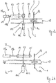
- manufacturing mold 1 is intended for the production of a rotor blade of a wind turbine.
- the manufacturing mold 1 has in this, not limiting example, two articulated steel frameworks 2, 3 interconnected. In each of the two steel frameworks 2, 3, a respective mold half shell 4, 5 is arranged.
- Fig. 1 is the one front right steel truss 2 fixedly mounted on the floor of an assembly hall, while the other in Fig. 1 upper, left steel truss 3 articulated example of seven joints 6 pivotally relative to a steel truss 2 is arranged.
- the one mold half shell 4 and in the other steel framework 3, the other half-mold shell 5 is mounted.
- the two half-shells 4, 5 are connected to their respective steel framework 2, 3.
- the one mold half-shell 4 is usually and preferably for producing a pressure side of the rotor blade and the other mold half-shell 5 is intended for the production of the suction side of the rotor blade.
- the one and the other support structure 2, 3 consist for example of a steel framework, in particular each of a steel tube construction, the two half-shells 4, 5, for example, each consist of laminate components.
- the two mold halves 4, 5 each have an open side and a closed side. In the in the Fig. 1 illustrated open position of the manufacturing mold 1, the two open sides of the two mold half shells 4, 5 are arranged side by side and face upwards - where "top" and "bottom” in the context of this application, information regarding the soil are. Facing away from the open side, heating devices can be integrated in the two mold halves 4, 5.
- the two rotor blade half shells from which the later rotor blade is assembled are first produced in the production mold 1.
- the layers thus arranged form a preferably dry semifinished product.
- the semifinished product is impregnated with a resin system in processes such as Resin Injection Molding (RIM) or Resin Transfer Molding (RTM).
- the other half-shell 5 can be pivoted with the rotor blade half shell made in the half shell by means of the other steel framework 3 over the one half shell 4.
- the manufacturing mold 1 is closed.
- the other rotor blade shell has a sufficient adhesion on the inside of the other half-mold shell 5, or is by a s.g. Closing vacuum and / or additional mechanical fuses secured so that it does not fall out of the other half-mold 5 when pivoting the other steel truss 3.
- one and another punches 8a, 8b of a respective spacer 8 abut each other and support the two steel frameworks 2, 3 against each other at their longitudinal sides opposite the joints and hold them at a predetermined distance d.
- the spacers 8 are preferably adjustable in length vertically by a few centimeters. Between the spacers 8 are provided along the longitudinal sides of the two steel trusses and the two half-shells 4, 5 with the steel frameworks 2, 3 in contact closures according to the invention 7, with which the two steel trusses together with the two half-shells can be closed against each other.
- the adhesive layer 9 may have a thickness of 2 to 4 cm. The adhesive 9 is applied thicker than the thickness of the later cured adhesive layer.
- the cured bond has a thickness of about 1-15 mm, so that after the collapse of the two half-molds 4, 5, the two half-shells 4, 5 must be pulled through the closures so far toward each other that the circumferential adhesive layer of 2 to 4 cm a final thickness of about 1-15 mm is pressed together.
- the pressed out adhesive 9 is collected outside the rotor blade.
- the contraction of the two half-shells is made possible by the closures 7, each having one or two actuators 10, 11.
- the number of actuators 10, 11 per closure 7 depends on the type of closure 7.
- the actuators 10, 11 are designed in their entirety so that they apply sufficient force to compress the mold half shells 4, 5 against the resistance of the 2 to 4 cm thick viscous adhesive layer 9 so far that the adhesive layer has its final thickness of 1-15 mm reached.
- the force to be applied by each actuator 10, 11 depends on the size of the surface of the adhesive layer, that is to say in particular on the length of the rotor blade or the two half-shells 4, 5 as well as the number of actuators 10, 11, which are arranged along the two longitudinal edges of the steel frameworks 2, 3.
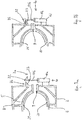
- Fig. 2a is a section of a gap of the folded, but not yet compressed, ie open manufacturing mold 1 between the pivotable mold part 3, 5 and the positionally fixed mold part 2, 4 shown.
- the edges of the mold half shells 4, 5 and the edges of the rotor blade half shells are aligned with each other.
- the adhesive layer 9 is applied to the edge of the positionally fixed rotor blade half shell, which extends over the entire width of the edges of the rotor blade half shells and covers the edge circumferentially around the rotor blade half shell, wherein only the root region, which has a circular opening in cross section perpendicular to the longitudinal direction, does not contact each other having to be bonded rotor blade half shell edges.
- the in Fig. 2a Shutter 7 shown is formed two-component.
- the closure comprises an actuator 10 of a closure component 7a, which is permanently mounted on the one steel framework 2, and another actuator 11 of another closure component 7b, which is permanently mounted on the other steel framework 3.
- the two closure components 7a, 7b act together.
- the two actuators 10, 11 In the unfolded position of the manufacturing mold 1, the two actuators 10, 11 in its open position, ie, the one actuator 10 is retracted, while the other actuator 11 is also retracted arranged.
- the actuators 10, 11 are designed here as hydraulic cylinders 10a, 11a with piston rods 10b, 11b.
- other embodiments of the actuators 10, 11 are conceivable, it may be electrical drives, pneumatic drives or other drives.
- the hydraulic systems with the liquid supply line and discharge and the control with pumps, etc. controlling the actuators 10, 11 are in the Fig. 2a, 2b not shown. They are known in the art, however.
- an eyelet 12 is mounted from the cylinder 10a.
- the eyelet 12 is arranged with its opening area perpendicular to the longitudinal direction L of the mold half shells.
- the eyelet may also be rotatable about the piston rod 10b.
- the piston rod automatically rotates in and out, so that the eyelet 12 in retracted, open state with her Opening cross-section is arranged parallel to the longitudinal direction of the mold half-shells and the eyelet 12 when extending the piston rod 10b by 90 ° either clockwise or counterclockwise rotates and is then arranged in the closed and closed state with its cross-sectional area perpendicular to the longitudinal direction of the mold half shells.
- the eyelet 12 cooperates with a arranged on another piston rod 11 b of the other hydraulic cylinder 11 a pin 13 which is insertable into the eyelet 12.
- a cross section over the entire longitudinal extent of the pin 13 is therefore smaller than an inner cross section of the eyelet 12th
- Fig. 2a Furthermore, two holders 14, 15 of the pin 13 are shown.
- the pin 13 In the unlocked state according to Fig. 2a the pin 13 is guided only in the first holder 14, in the locked state, the in Fig. 2b is shown, the pin 13 is moved by means of the other actuator 11 to the right in the locked position, while the pin 13 is mounted in a first holder 14 and the pin 13 is guided during the locking operation by the eyelet 12 and a pin tip in a second holder 15, which is provided on the first bracket 14 opposite side of the eyelet 12 introduced.
- the pin 13 is in a locked state in two brackets 14, 15 which are fixedly connected to the other steel truss 3, stored.
- the bearing of the pin 13 is zugstabil particularly in the direction of gravity, so that by re-pressing the one actuator 10, the eyelet 12 can be pulled a bit towards the ground.
- the closed production mold 1 is closed, ie the two mold halves 4, 5 are further contracted.
- the spacers 8 are shown with.
- the spacers 8 in this embodiment are pairs of cooperating punches 8a, 8b, which are each fixedly mounted on the steel framework 2 or the other steel truss 3; when the manufacturing mold 1 is closed, the stamps 8a, 8b, which interact in pairs, move exactly toward one another until they touch each other.
- the Punch 8a, 8b are adjustable in length and adjusted so that they are in contact with each other in the closed state of the manufacturing mold 1 and not further towards each other, when the two edges of the rotor blade half shells have the predetermined distance of 1 cm to each other.
- FIGS. 3a and 3b a second embodiment of the closure 7 according to the invention is shown.
- FIG. 2 shows a cross-sectional view of the opened production mold 1 with a rotor blade half shell 20 arranged in the one mold half shell 4 and another rotor blade half shell 21 arranged in the other half shell 5.
- the folded edges of the two half-molds 4, 5 are not completely folded.
- the closure 7 is, as in the first embodiment, automatically closable.
- the mounted on steel truss 2 component 7a of the closure 7 in turn has a cylinder 10a with a relative to the cylinder 10a movable piston rod 10b, at its free end a boom 22 is mounted, which in this embodiment has a cross-section, for example, triangular shape and in the longitudinal direction has an extension of several centimeters, preferably 10 to 15 cm.
- the other closure component 7b is a trailer mounted on the other steel framework 3, which protrudes from the other steel framework 3 on the outside.
- Fig. 3a the shutter 7 is shown in the open position.
- Fig. 3b the shutter 7 is shown in the closed position.
- the boom 22 is away from the mold half-shell 4.
- a trailer 23 mounted on the other steel framework 3 is arranged in the direction of the force of gravity underneath the boom 22.
- the boom 22 is then rotated by 180 ° by means of the piston rod 10b, so that the boom 22 is arranged above the trailer 23.
- the trailer 23 is in turn formed in cross section perpendicular to the longitudinal direction, for example triangular.
- a bearing surface of the cantilever 22 and a bearing surface of the Auflegers 23 are arranged parallel to each other and touch each other in the closed state of the closure 7 Fig. 3b ,
- the actuator of the closure component 7a is actuated and the piston rod 10b is retracted, so that the boom 22 and the trailer 23 come into contact with each other at their two bearing surfaces.
- the actuator 10 is actuated further and under force, the two mold half shells 4, 5 pressed to each other, until the arranged between the edges of the rotor blade half shells 20, 21 adhesive, which is applied in a layer thickness of here also 2 to 4 cm, to a layer thickness of about 1- 15 mm is compressed.
- the thickness of the adhesive layers is also dependent on the rotor blade to be produced, so that the layer thicknesses are mentioned here only as an example and also other thicknesses of the adhesive layer 9 are conceivable, both in terms of the initial application and in terms of the final thickness to which they are compressed become.
Landscapes
- Engineering & Computer Science (AREA)
- Mechanical Engineering (AREA)
- Wind Motors (AREA)
Abstract
Description
- Die Erfindung betrifft eine Herstellungsform für ein Rotorblatt einer Windenergieanlage nach dem Oberbegriff des Anspruchs 1.
- Herstellungsformen für Rotorblätter von Windenergieanlagen sind im Stand der Technik natürlich hinlänglich bekannt.
- Dabei werden gemäß der
WO 2010/076605 A1 zwei Formhalbschalen, die auf Gerüsten montiert sind, gegeneinander verschwenkt, bis Ränder der Formhalbschalen übereinander positioniert sind und in jeder der beiden Formhalbschalen ist eine Rotorblatthalbschale eingelegt. Zwischen den Rotorblatthalbschalen wird auf dem Rand der unteren Rotorblatthalbschale eine Klebmasse aufgebracht. Die beiden Formhalbschalen werden mittels eines angetriebenen Hakens ineinander verhakt, dabei führt der Haken eine kombinierte Dreh- und translatorische Bewegung aus, wobei die beiden Bewegungen miteinander unmittelbar gekoppelt sind. - In der
WO 2010/103490 A1 ist ein Schließmechanismus für die beiden Formhalbschalen einer Herstellungsform beschrieben, wobei der Verschluss ebenfalls auf einem Hakenmechanismus basiert. Der Haken wiederum ist an einem Zylinder angeordnet, der eine translatorische Bewegung ausführt, sodass der Haken selber eine kombinierte translatorische und Drehbewegung durchführt, wobei beide Bewegungen voneinander nicht entkoppelt sind. Nachteilig an den beiden beschriebenen Verschlussmechanismen der Herstellungsform ist, dass die beiden Verschlusskomponenten ziemlich genau zueinander positioniert werden müssen, damit der Stift sich in der eindimensionalen Bewegungslinie des Hakens befindet. - Es ist daher in einem ersten Aspekt Aufgabe der vorliegenden Erfindung, eine Herstellungsform der eingangs genannten Art mit einem anderen Verschluss zu versehen, der die oben genannten Nachteile vermeidet.
- Es ist in einem zweiten Aspekt Aufgabe der vorliegenden Erfindung, ein Verfahren zur Verfügung zu stellen, durch das eine Herstellungsform eines Rotorblatts einer Windenergieanlage besser verschlossen werden kann.
- In dem ersten Aspekt wird die Aufgabe durch eine Herstellungsform mit dem Merkmal des Anspruchs 1 gelöst.
- Die Herstellungsform ist zur Herstellung eines Rotorblattes einer Windenergieanlage bestimmt, wobei das Rotorblatt ein Laminatbauteil ist, das zumindest aus zwei Rotorblatthalbschalen aufgebaut ist und jede der Rotorblatthalbschalen in einem Laminierverfahren hergestellt ist, wobei Gewebelagen aus textilem Gewebe und/oder Kunststoffgewebe, mit beispielsweise Kohlefasern, die in bestimmten Richtungen ausgerichtet sind, übereinander gelegt werden. Dabei können zusätzlich Schaumstoffkerne und/oder Balsa verwendet werden. Diese übereinandergelegten Schichten werden anschließend in einem Infusionsverfahren mit einem Harzsystem infundiert, wobei der Begriff der "Infusion" hier allgemein zu verstehen ist und es nicht auf die konkrete Ausgestaltung des Infusionsverfahrens ankommt. Es können aber auch andere Verfahren zur Herstellung eines Bauteils aus Faserverbundwerkstoffen zum Einsatz kommen.
- Die Herstellungsform umfasst zwei Formhalbschalen mit jeweils einer offenen Seite, wobei jede der Formhalbschalen auf einer Halteeinrichtung angeordnet ist. Die eine Formhalbschale ist auf der einen Halteeinrichtung, die andere Formhalbschale auf der anderen Halteeinrichtung angeordnet. Die beiden Halteeinrichtungen können gelenkig miteinander verbunden sein. Sie sind zwischen einer geöffneten Stellung, in der die beiden Formhalbschalen mit ihrer offenen Seite nach oben weisen, nebeneinander angeordnet und einer geschlossenen Stellung, in der die beiden Formhalbschalen mit ihrer offenen Seite zueinander weisend übereinander angeordnet sind, hin und her bewegbar. Die Angaben "oben" und "unten" sind hier unter Bezugnahme auf die Erdanziehungskraft zu verstehen.
- Erfindungsgemäß weist die Herstellungsform eine Mehrzahl, d. h. wenigstens zwei, drei, vier oder jede höhere Anzahl an zweikomponentigen Verschlüssen auf, deren eine Komponente an der einen Halteeinrichtung und deren andere Komponente an der anderen Halteeinrichtung angeordnet ist. Dabei sind die Komponenten fest an den Halteeinrichtungen montiert, sodass sie auch hohen Belastungen Stand halten können.
- Die beiden Komponenten sind vorzugsweise automatisch und mittels wenigstens eines Aktuators miteinander durch wenigstens zwei voneinander entkoppelte Bewegungen einer Komponente bzw. der beiden Komponenten verschließbar und wieder öffenbar. Die Komponenten sind automatisch betätigbar, d. h. sie brauchen nicht manuell betätigt zu werden. Der Verschluss wird von außen elektronisch, pneumatisch, hydraulisch usw. gesteuert, wobei einzelne Schritte des Verschließvorganges für sich separat gesteuert werden können.
- Jeder der Verschlüsse weist wenigstens einen Aktuator auf. Die Verschlüsse können auch zwei oder jede höhere Anzahl an Aktuatoren aufweisen. Günstigerweise weist der Verschluss genau einen Aktuator auf. In einer anderen Ausführungsform der Erfindung weist die eine Komponente des Verschlusses genau einen Aktuator und die andere Komponente des Verschlusses genau einen anderen Aktuator auf. Die beiden Aktuatoren sind voneinander beabstandet und vorzugsweise separat steuerbar.
- Die wenigstens zwei Bewegungen der Komponenten bzw. der Komponente sind entkoppelt. Sie sind unabhängig voneinander. Jeder der Verschlüsse hat daher insbesondere zwei Freiheitsgrade.
- Es ist daher durchaus möglich, dass eine Bewegung der einen Komponente nur ein kurzes Stück weit ausgeführt wird, dann durch ein kurzes Stück einer Bewegung der anderen Komponente ergänzt wird und dann wieder die erste Bewegung ein weiteres Stück weit ausgeführt wird.
- Vorzugsweise weist die eine Komponente eine Öse auf, die von einem Aktuator angetrieben ist und die andere Komponente weist einen Bolzen auf, der über einen anderen Aktuator angetrieben ist und in einem geschlossenen Zustand in die Öse eingeführt ist und im geöffneten Zustand aus der Öse herausgezogen ist. Vorzugsweise ist der Bolzen in eine ersten Halterung geführt und berührt im geöffneten Zustand nur die erste Halterung, während er im geschlossenen Zustand durch die Öse hindurch geführt ist und auch in eine zweite Halterung eingeführt ist, die er auch berührt.
- In einer anderen Ausführungsform des erfindungsgemäßen Verschlusses weist die eine Komponente einen Ausleger auf, der rotierbar ist, während die andere Komponente eine Auflage aufweist, über die der Ausleger bei zusammengeklappter Herstellungsform drehbar ist. Darüber hinaus ist der Ausleger translatorisch in einer Richtung verfahrbar, wobei die Richtung vom Ausleger zum Aufleger hinweist.
- In der bevorzugten Ausführungsform der Erfindung weist der eine oder der andere Aktuator einen in einer Kulisse geführten Stift auf, an dessen freiem Ende die Öse oder der Ausleger angeordnet ist. Unter einer Kulisse kann hier ein Zylinder verstanden werden und unter dem Stift eine Zylinderstange, die durch den Zylinder pneumatisch, hydraulisch angetrieben wird. Es sind jedoch auch elektrische oder anderweitige Antriebe denkbar.
- Günstigerweise bilden die beiden Formhalbschalen im geschlossenen Zustand der Herstellungsform einen zwischen ihren Rändern entlang laufenden Spalt aus. Der Spalt erstreckt sich vorzugsweise über die gesamte Ausdehnung der beiden übereinander angeordneten Formhalbschalenränder sowohl entlang der Breite als auch entlang der Längsrichtung der Ränder.
- In den Formhalbschalen sind Rotorblatthalbschalen gefertigt und weisen ebenfalls jeweils einen Rand auf, der entlang dem Rand der Formhalbschalen verläuft, vorzugsweise fluchten die Ränder der Formhalbschale und die der Rotorblatthalbschale.
- Zweckmäßigerweise fluchten alle nebeneinander angeordneten Ränder und besonders bevorzugt fluchten die Ränder überall. Dadurch entspricht der Spalt zwischen den Rändern der Formhalbschalen dem Spalt zwischen den Rändern der Rotorblatthalbschalen an den Stellen, wo die Ränder fluchten.
- Ein Klebmittel ist auf die Ränder der Rotorblatthalbschalen aufgebracht, über die die beiden in den Formhalbschalen gefertigten und vorzugsweise bereits ausgehärteten Rotorblatthalbschalen miteinander verklebt werden. Das heißt, die Klebmasse wird auf zumindest einen Rand einer Rotorblatthalbschale aufgebracht, die in der Formhalbschale positioniert ist und die beiden Rotorblatthalbschalen werden entlang ihrer Ränder aufeinander gedrückt.
- In einer bevorzugten Ausführungsform der Erfindung sind an den beiden Halteeinrichtungen Abstandshalter vorgesehen, die im geschlossenen Zustand die beiden Formhalbschalen so weit voneinander beabstanden, dass sich zwischen den Rändern der Rotorblatthalbschalen der Spalt, vorzugsweise reproduzierbar in einer definierten Höhe ausbildet.
- Vorzugsweise sind die Abstandshalter als Stempelpaar ausgebildet, wobei jeweils einer der Stempel an einer der Halteeinrichtungen fest montiert ist, sodass er den erforderlichen Zug-, und Druckbelastungen Stand hält. Im geschlossenen Zustand der Herstellungsform liegen die Stempel eines Paares jeweils aufeinander und berühren sich.
- Besonders bevorzugt ist die Halteeinrichtung und/oder die andere Halteeinrichtung als Stahlfachwerk ausgebildet. Beim Stahlfachwerk handelt es sich um eine Fachwerkkonstruktion aus Stahlträgern und/oder Stahlrohren.
- Die Erfindung wird in ihrem anderen Aspekt durch ein Verfahren mit dem Merkmal des Anspruchs 10 gelöst.
- Das Verfahren eignet sich insbesondere zur Durchführung mit einer der oben genannten Herstellungsformen.
- In jeder der beiden Formhalbschalen wird jeweils eine Rotorblatthalbschale gefertigt. Nachdem die Rotorblatthalbschalen als Laminatbauteile mit Harz infundiert und/oder zumindest weitgehend ausgehärtet, vorzugsweise vollständig ausgehärtet sind, werden die beiden Formhalbschalen übereinander zusammen geklappt, sodass die Ränder der beiden in den Formhalbschalen befindlichen Rotorblatthalbschalen übereinander positioniert sind.
- Günstigerweise wird auf zumindest einen der Ränder der Rotorblatthalbschalen ein Klebmittel vorher aufgebracht und die beiden Formhalbschalen werden soweit zusammen geklappt, dass sowohl der Rand der einen Rotorblatthalbschale als auch der Rand der anderen Rotorblatthalbschale sich gegenüberliegend auf der Klebmasseschicht aufliegen.
- Vorzugsweise werden anschließend die beiden Formhalbschalen mit erfindungsgemäßen zweikomponentigen Verschlüssen verschlossen, deren eine Komponente an einer Halteeinrichtung und deren andere Komponente an der anderen Halteeinrichtung angeordnet sind. Die beiden Komponenten jedes Verschlusses werden durch zwei voneinander entkoppelte Bewegungen einer oder beider Komponente miteinander verschlossen.
- Vorzugsweise wird eine an der einen Komponente vorgesehene Öse in eine Richtung translatorisch verfahren und ein an der anderen Komponente angeordneter Bolzen wird ebenfalls translatorisch in eine Richtung verfahren bis der Bolzen durch die Öse hindurchragt. Dann wird die Öse vorzugsweise in die entgegengesetzte Richtung translatorisch verfahren. Die Bolzenbewegung und die Bewegungsrichtung der Öse verlaufen vorzugsweise senkrecht zueinander, günstigerweise in etwa senkrecht zueinander, wobei auch ein Winkel von 90° ± 5°, ± 10°, günstigerweise ± 15° zwischen den beiden translatorischen Bewegungen auftreten kann. Die Öse wird soweit translatorisch in die entgegengesetzte Richtung verfahren, bis der von ihr mitgenommene Bolzen hinreichend weit zur Formhalbschale gezogen wird, dass der Spalt zwischen den beiden Rotorblatthalbschalen die vorgegebene Spaltbreite aufweist. Der zusammengedrückte Spalt ist vorzugsweise vollständig von Klebmittel ausgefüllt, sodass eine hinreichend feste Klebverbindung zwischen den Rändern der beiden Rotorblatthalbschalen erzeugt wird.
- In einer anderen Ausführungsform des erfindungsgemäßen Verfahrens wird ein an der einen Komponente angeordneter Ausleger rotiert, günstigerweise ist der Ausleger an einer Stange angeordnet, um deren Längsrichtung der Ausleger rotiert wird, bis er über einem an der anderen Komponente angeordneten Aufleger positioniert ist. Nach der Drehung des Auslegers ist der Ausleger vom Aufleger beabstandet, d. h. Ausleger und Aufleger berühren sich nicht, aber Auflageflächen liegen vorzugsweise im Wesentlichen parallel zueinander in einem lichten Abstand voneinander.
- Dann wird der Ausleger in die Richtung des Auflegers translatorisch verfahren, bis der Ausleger den Aufleger berührt. Der Ausleger wird vorzugsweise mittels des Aktuators aber noch weiter verfahren, sodass er unter Krafteinwirkung die andere Formhalbschale auf die Formhalbschale bzw. auf den aufgetragenen Kleber presst, solange, bis der Spalt die vorbestimmte Spaltbreite erreicht hat.
- Günstigerweise wird das Klebmittel zunächst in einer Schichtdicke von 3 bis 4 cm aufgetragen, während der nach dem Zusammendrücken entstehende Spalt zwischen den beiden Rotorblatthalbschalenrändern nur etwa 1 cm beträgt. Auf der Spaltbreite wird die Klebmittelschicht zusammengedrückt und dabei seitlich aus dem Spalt weggedrückt.
- Es sind natürlich auch andere Klebmittelschichtdicken denkbar und möglich, insbesondere kann die Klebmasseschicht auch in Dicken von 4 bis 5 cm oder 5 bis 6 cm aufgetragen werden, während die Spaltbreite nach dem Zusammendrücken etwa 1 bis 1,5 cm oder sogar 2 cm beträgt.
- Die Erfindung wird anhand von zwei Ausführungsbeispielen in fünf Figuren beschrieben, dabei zeigen:
- Fig. 1
- eine perspektivische Ansicht einer Herstellungsform eines Rotorblattes einer Windenergieanlage,
- Fig. 2a
- eine erste Ausführungsform eines Verschlusses der Herstellungsform in
Fig. 1 in einem geöffneten Zustand, - Fig. 2b
- den Verschluss in
Fig. 2a in einem geschlossenen Zustand, - Fig. 3a
- eine zweite Ausführungsform eines Verschlusses in einer geöffneten Position,
- Fig. 3b
- den Verschluss in
Fig. 3a mit zusammengeklappter Herstellungsform und in verschlossenem Zustand. - Die in
Fig. 1 dargestellte Herstellungsform 1 ist zur Herstellung eines Rotorblattes einer Windenergieanlage bestimmt. - Die Herstellungsform 1 weist in diesem, nicht einschränkend zu verstehenden Beispiel zwei gelenkig miteinander verbundene Stahlfachwerke 2, 3 auf. In jedem der beiden Stahlfachwerke 2, 3 ist jeweils eine Formhalbschale 4, 5 angeordnet. In der
Fig. 1 ist das eine vordere rechte Stahlfachwerk 2 positionsfest auf dem Boden einer Montagehalle montiert, während das andere inFig. 1 obere, linke Stahlfachwerk 3 gelenkig beispielhaft an sieben Gelenken 6 verschwenkbar relativ gegenüber dem einen Stahlfachwerk 2 angeordnet ist. In dem einen Stahlfachwerk 2 ist die eine Formhalbschale 4 und in dem anderen Stahlfachwerk 3 die andere Formhalbschale 5 montiert. Die beiden Formhalbschalen 4, 5 sind mit ihrem jeweiligen Stahlfachwerk 2, 3 verbunden. Die Verbindung erlaubt günstigerweise geringfügige Relativbewegungen aufgrund von unterschiedlichen thermischen Ausdehnungen, ansonsten ist die Verbindung günstigerweise relativ positionsfest. Die eine Formhalbschale 4 ist üblicherweise und bevorzugt zur Herstellung einer Druckseite des Rotorblattes und die andere Formhalbschale 5 ist zur Fertigung der Saugseite des Rotorblattes bestimmt. - Die eine und die andere Haltekonstruktion 2, 3 bestehen beispielsweise aus einem Stahlfachwerk, insbesondere jeweils aus einer Stahlrohrkonstruktion, die beiden Formhalbschalen 4, 5 bestehen beispielsweise jeweils aus Laminatbauteilen. Die beiden Formhalbschalen 4, 5 weisen jeweils eine offene Seite und eine geschlossene Seite auf. In der in der
Fig. 1 dargestellten geöffneten Position der Herstellungsform 1 sind die beiden offenen Seiten der beiden Formhalbschalen 4, 5 nebeneinander angeordnet und weisen nach oben - wobei "oben" und "unten" im Rahmen dieser Anmeldung, Angaben bezüglich des Erdbodens sind. Der offenen Seite abgewandt können in den beiden Formhalbschalen 4, 5 Heizvorrichtungen integriert sein. - Während des Herstellungsverfahrens des Rotorblattes werden zunächst die beiden Rotorblatthalbschalen, aus denen das spätere Rotorblatt zusammengesetzt wird, in der Herstellungsform 1 gefertigt. Dazu werden in jede der beiden Formhalbschalen 4, 5, gemäß
Fig. 1 , zunächst mehrere Schichten, beispielsweise faserhaltige Lagen, Schäume, Balsa, usw. übereinander und/oder nebeneinander gelegt. Die so angeordneten Schichten bilden ein vorzugsweise trockenes Halbzeug aus. Das Halbzeug wird in Verfahren, wie beispielsweise Resin Injection Moulding (RIM-Verfahren) oder Resin Transfer Moulding (RTM-Verfahren) mit einem Harzsystem getränkt. - Nachdem die Rotorblatthalbschalen 20, 21 fertig gestellt und ausgehärtet sind, kann die andere Formhalbschale 5 mit der in der Formhalbschale gefertigten Rotorblatthalbschale mithilfe des anderen Stahlfachwerkes 3 über die eine Formhalbschale 4 verschwenkt werden. Die Herstellungsform 1 wird zugeklappt. Die andere Rotorblattschale hat eine hinreichende Haftung auf der Innenseite der anderen Formhalbschale 5, bzw. ist durch ein s.g. Schließvakuum und/oder zusätzliche mechanische Sicherungen gesichert, sodass sie beim Verschwenken des anderen Stahlfachwerkes 3 nicht aus der anderen Formhalbschale 5 herausfällt.
- Einander zugewandte Längsseiten der beiden Stahlfachwerke 2, 3 sind über die Gelenke 6 miteinander verbunden und ermöglichen so das Hin- und Herverschwenken des anderen Stahlfachwerkes 3, während die den Gelenken 6 gegenüberliegenden Längsseiten der beiden Stahlfachwerke 2, 3 mit einer Mehrzahl an Komponenten 7a, 7b mehrerer Verschlüsse 7 sowie zusammenwirkenden Komponenten 8a, 8b von Abstandshaltern 8 versehen sind.
- Beim Zusammenklappen der Herstellungsform 1 stoßen ein und ein anderer Stempel 8a, 8b jeweils eines Abstandshalters 8 aufeinander und stützen die beiden Stahlfachwerke 2, 3 an ihrer den Gelenken gegenüber liegenden Längsseiten gegeneinander ab und halten sie auf einem vorbestimmten Abstand d. Die Abstandshalter 8 sind in der Vertikalen vorzugsweise um einige Zentimeter längenverstellbar. Zwischen den Abstandshaltern 8 sind entlang der Längsseiten der beiden Stahlfachwerke und der beiden Formhalbschalen 4, 5 mit den Stahlfachwerken 2, 3 in Berührung stehende erfindungsgemäße Verschlüsse 7 vorgesehen, mit denen die beiden Stahlfachwerke samt der beiden Formhalbschalen gegeneinander verschlossen werden können.
- Bevor der klappbare Teil 3, 5 der Herstellungsform 1, also das andere Stahlfachwerk 3 und die andere Formhalbschale 5 auf das positionsfeste Teil, also das eine Stahlfachwerk 2 und die eine Formhalbschale 4, geklappt wird, werden die Ränder der Rotorblatthalbschalen sowie die freien Ränder der in die positionsfeste Rotorblatthalbschale geklebten Stege mit einer Klebmittelschicht versehen. Die Klebmittelschicht 9 kann eine Dicke von 2 bis 4 cm aufweisen. Das Klebmittel 9 ist dicker aufgetragen als die Dicke der später ausgehärteten Klebstoffschicht. Die ausgehärtete Verklebung weist eine Dicke von etwa 1-15 mm auf, sodass nach dem Zuklappen der beiden Formhalbschalen 4, 5 die beiden Formhalbschalen 4, 5 durch die Verschlüsse soweit aufeinander zu gezogen werden müssen, dass die umlaufende Klebmittelschicht von 2 bis 4 cm auf eine Enddicke von etwa 1-15 mm zusammen gedrückt wird. Das herausgedrückte Klebmittel 9 wird außen am Rotorblatt aufgefangen. Das Zusammenziehen der beiden Formhalbschalen wird durch die Verschlüsse 7 ermöglicht, die jeweils einen oder zwei Aktuatoren 10, 11 aufweisen. Die Anzahl der Aktuatoren 10, 11 pro Verschluss 7 hängt von der Bauart des Verschlusses 7 ab.
- Die Aktuatoren 10, 11 sind in ihrer Gesamtheit so ausgelegt, dass sie eine hinreichende Kraft aufbringen, um die Formhalbschalen 4, 5 gegen den Widerstand der 2 bis 4 cm dicken zähklebrigen Klebmasseschicht 9 so weit zusammenzudrücken, dass die Klebmasseschicht ihre Enddicke von 1-15 mm erreicht. Die von jedem Aktuator 10, 11 tatsächlich aufzubringende Kraft hängt dabei natürlich von der Größe der Fläche der Klebmasseschicht ab, also insbesondere der Länge des Rotorblattes bzw. der beiden Formhalbschalen 4, 5 sowie auch von der Anzahl der Aktuatoren 10, 11, die entlang der beiden Längskanten der Stahlfachwerke 2, 3 angeordnet sind.
- In
Fig. 2a ist ein Ausschnitt eines Spaltes der zusammengeklappten, aber noch nicht zusammengedrückten, d.h. offenen Herstellungsform 1 zwischen dem schwenkbaren Formteil 3, 5 und dem positionsfesten Formteil 2, 4 dargestellt. Innenseitig der Ränder der beiden Formhalbschalen 4, 5 ist jeweils ein Rand der zugeordneten Rotorblatthalbschalen angeordnet. Die Ränder der Formhalbschalen 4, 5 und die Ränder der Rotorblatthalbschalen fluchten miteinander. - Auf den Rand der positionsfesten Rotorblatthalbschale ist die Klebmasseschicht 9 aufgetragen, die sich über die gesamte Breite der Ränder der Rotorblatthalbschalen erstreckt und den Rand umlaufend um die Rotorblatthalbschale abdeckt, wobei lediglich der Wurzelbereich, der im Querschnitt senkrecht zur Längsrichtung eine kreisförmige Öffnung aufweist, keine miteinander zu verklebenden Rotorblatthalbschalenränder aufweist.
- Der in
Fig. 2a dargestellte Verschluss 7 ist zweikomponentig ausgebildet. Der Verschluss weist einen Aktuator 10 einer Verschlusskomponente 7a auf, die an dem einen Stahlfachwerk 2 dauerhaft montiert ist, sowie einen anderen Aktuator 11 einer anderen Verschlusskomponente 7b auf, die an dem anderen Stahlfachwerk 3 dauerhaft montiert ist. Die beiden Verschlusskomponenten 7a, 7b wirken zusammen. In der aufgeklappten Position der Herstellungsform 1 sind die beiden Aktuatoren 10, 11 in ihrer geöffneten Stellung, d. h. der eine Aktuator 10 ist eingezogen, während der andere Aktuator 11 ebenfalls eingezogen ist, angeordnet. Die Aktuatoren 10, 11 sind hier als hydraulische Zylinder 10a, 11a mit Kolbenstange 10b, 11 b ausgebildet. Es sind jedoch auch andere Ausführungsformen der Aktuatoren 10, 11 denkbar, es kann sich um elektrische Antriebe, pneumatische Antriebe oder andere Antriebe handeln. Die die Aktuatoren 10, 11 steuernden Hydrauliksysteme mit Flüssigkeitszufuhrleitung und -ableitung und einer Steuerung mit Pumpen usw. sind in derFig. 2a, 2b nicht dargestellt. Sie sind im Stand der Technik aber bekannt. - Von dem Zylinder 10a geht eine relativ zum Zylinder 10a bewegliche Kolbenstange 10b ab, an deren freien, in
Fig. 2a oberen Ende, eine Öse 12 montiert ist. Die Öse 12 ist mit ihrer Öffnungsfläche senkrecht zur Längsrichtung L der Formhalbschalen angeordnet. Die Öse kann auch um die Kolbenstange 10b drehbar angeordnet sein. In einigen Ausführungsformen des Verschlusses dreht sich die Kolbenstange automatisch beim Herein- und Herausfahren, sodass die Öse 12 im eingefahrenen, geöffneten Zustand mit ihrem Öffnungsquerschnitt parallel zur Längsrichtung der Formhalbschalen angeordnet ist und sich die Öse 12 beim Ausfahren der Kolbenstange 10b um 90° entweder im Uhrzeigersinn oder entgegen dem Uhrzeigersinn dreht und im zugeklappten und im geschlossenem Zustand dann mit ihrer Querschnittsfläche senkrecht zur Längsrichtung der Formhalbschalen angeordnet ist. Die Öse 12 wirkt mit einem an einer anderen Kolbenstange 11 b des anderen Hydraulikzylinders 11a angeordneten Zapfen 13 zusammen, der in die Öse 12 einführbar ist. Ein Querschnitt über die gesamte Längsausdehnung des Zapfens 13 ist daher kleiner als ein Innenquerschnitt der Öse 12. - In
Fig. 2a sind des Weiteren zwei Halterungen 14, 15 des Zapfens 13 dargestellt. Im nicht verriegelten Zustand gemäßFig. 2a ist der Zapfen 13 lediglich in der ersten Halterung 14 geführt, im verriegelten Zustand, der inFig. 2b dargestellt ist, wird der Zapfen 13 mittels des anderen Aktuators 11 nach rechts in die verriegelte Stellung verschoben, dabei ist der Zapfen 13 in einer ersten Halterung 14 gelagert und der Zapfen 13 wird beim Verriegelungsvorgang durch die Öse 12 geführt und eine Zapfenspitze in eine zweite Halterung 15, die auf der der ersten Halterung 14 gegenüberliegenden Seite der Öse 12 vorgesehen ist, eingeführt. Der Zapfen 13 ist in einem verriegelten Zustand in zwei Halterungen 14, 15, die fest mit dem anderen Stahlfachwerk 3 verbunden sind, gelagert. Die Lagerung des Zapfens 13 ist insbesondere in Richtung der Erdanziehungskraft zugstabil, sodass durch erneutes Betätigen des einen Aktuators 10 die Öse 12 ein Stück weit in Richtung des Erdbodens gezogen werden kann. Dadurch wird die zugeklappte Herstellungsform 1 geschlossen, d.h. die beiden Formhalbschalen 4, 5 werden weiter zusammengezogen. - Durch gleichzeitiges Einziehen der Ösen 12 aller Verschlüsse 7 entlang der Längsseiten der Stahlfachwerke 2, 3 werden die beiden Ränder der in den Formhalbschalen 4, 5 gelagerten Rotorblatthalbschalen aufeinandergedrückt, bis sie den vorbestimmten Abstand d von 1-15 mm zueinander aufweisen. Während des Zusammenziehens der beiden Formhalbschalen 4, 5 wird das zwischen den beiden Rändern der Formhalbschalen 4, 5 aufgebrachte Klebmittel 9 rotorblattinnenseitig und rotorblattaußenseitig herausgedrückt.
- In den
Fig. 2a, 2b sind die Abstandshalter 8 mit eingezeichnet. Bei den Abstandshaltern 8 handelt es sich bei dieser Ausführungsform um paarweise zusammenwirkende Stempel 8a, 8b, die jeweils positionsfest an dem Stahlfachwerk 2 bzw. dem anderen Stahlfachwerk 3 montiert sind; beim Zuklappen der Herstellungsform 1 bewegen sich die paarweise zusammenwirkenden Stempel 8a, 8b exakt aufeinander zu bis sie sich berühren. Die Stempel 8a, 8b sind in ihrer Länge einstellbar und so eingestellt, dass sie im geschlossenen Zustand der Herstellungsform 1 genau dann Kontakt miteinander aufweisen und nicht weiter aufeinander zu bewegbar sind, wenn die beiden Ränder der Rotorblatthalbschalen den vorbestimmten Abstand von 1 cm zueinander aufweisen. - In den
Figuren 3a und 3b ist eine zweite Ausführungsform des erfindungsgemäßen Verschlusses 7 dargestellt. - In
Fig. 3a ist eine Querschnittansicht der geöffneten Herstellungsform 1 mit einer in der einen Formhalbschale 4 angeordneten Rotorblatthalbschale 20 und in der anderen Formhalbschale 5 angeordneten anderen Rotorblatthalbschale 21 dargestellt. Die geklappten Ränder der beiden Formhalbschalen 4, 5 sind nicht ganz aufeinander geklappt. Der Verschluss 7 ist, wie in der ersten Ausführungsform, automatisch verschließbar. Die am Stahlfachwerk 2 montierte Komponente 7a des Verschlusses 7 weist wiederum einen Zylinder 10a mit einer relativ zum Zylinder 10a beweglichen Kolbenstange 10b auf, an deren freiem Ende ein Ausleger 22 montiert ist, der in dieser Ausführungsform eine im Querschnitt z.B. dreieckige Form hat und in Längsrichtung eine Ausdehnung von mehreren Zentimetern, vorzugsweise 10 bis 15 cm hat. Die andere Verschlusskomponente 7b ist ein an dem anderen Stahlfachwerk 3 montierter Aufleger, der außenseitig vom anderen Stahlfachwerk 3 absteht. - In
Fig. 3a ist der Verschluss 7 in der geöffneten Stellung dargestellt. InFig. 3b ist der Verschluss 7 in der geschlossenen Stellung dargestellt. In der geöffneten Stellung gemäßFig. 3a weist der Ausleger 22 von der Formhalbschale 4 weg. Nachdem die klappbare Formhalbschale 5 auf die positionsfeste Formhalbschale 4 geklappt wurde, ist ein an dem anderen Stahlfachwerk 3 montierter Aufleger 23 in Richtung der Erdanziehungskraft unterhalb des Auslegers 22 angeordnet. Der Ausleger 22 wird dann mittels der Kolbenstange 10b um 180° gedreht, sodass der Ausleger 22 über dem Aufleger 23 angeordnet ist. Der Aufleger 23 ist wiederum im Querschnitt senkrecht zur Längsrichtung z.B. dreieckig ausgebildet. Eine Auflagefläche des Auslegers 22 und eine Auflagefläche des Auflegers 23 sind parallel zueinander angeordnet und berühren sich im geschlossenen Zustand des Verschlusses 7 gemäßFig. 3b . - Um die Herstellungsform 1 zu schließen, wird der Aktuator der Verschlusskomponente 7a betätigt und die Kolbenstange 10b eingezogen, sodass der Ausleger 22 und der Aufleger 23 an ihren beiden Auflageflächen miteinander in Berührung gelangen. Der Aktuator 10 wird weiter betätigt und unter Kraft werden die beiden Formhalbschalen 4, 5 zueinander gedrückt, solange bis das zwischen den Rändern der Rotorblatthalbschalen 20, 21 angeordnete Klebmittel, das in einer Schichtdicke von hier ebenfalls 2 bis 4 cm aufgetragen wird, auf eine Schichtdicke von etwa 1-15 mm zusammengedrückt ist.
- Grundsätzlich ist es so, dass die Dicke der Klebmasseschichten auch abhängig ist vom herzustellenden Rotorblatt, sodass die Schichtdicken hier nur exemplarisch genannt werden und auch andere Dicken der Klebmittelschicht 9 denkbar sind, sowohl hinsichtlich des anfänglichen Auftrags als auch hinsichtlich der schlussendlichen Dicke auf die sie zusammengedrückt werden.
-
- 1
- Herstellungsform
- 2
- Haltekonstruktion, z. B. Stahlfachwerk
- 3
- Haltekonstruktion, z. B. Stahlfachwerk
- 4
- Formhalbschale
- 5
- Formhalbschale
- 6
- Gelenke
- 7
- Verschlüsse
- 7a
- Verschlusskomponente
- 7b
- Verschlusskomponente
- 8
- Abstandshalter
- 8a
- Stempel
- 8b
- Stempel
- 9
- Klebmittelschicht
- 10
- Aktuator
- 10a
- Zylinder
- 10b
- Kolbenstange
- 11
- Aktuator
- 11a
- Zylinder
- 11b
- Kolbenstange
- 12
- Öse
- 13
- Zapfen
- 14
- Halterung
- 15
- Halterung
- 19
- Spalt
- 20
- Rotorblatthalbschale
- 21
- Rotorblatthalbschale
- 22
- Ausleger
- 23
- Aufleger
- d
- Abstand
- L
- Längsrichtung
Claims (12)
- Herstellungsform (1) für ein Rotorblatt einer Windenergieanlage mit zwei Formhalbschalen (4, 5) mit jeweils einer offenen Seite und die jeweils in einer Halteeinrichtung (2, 3) angeordnet sind, wobei
die beiden Halteeinrichtungen (2, 3) gelenkig miteinander verbunden sind und von einer geöffneten Position, in der die beiden Formhalbschalen (4, 5) mit ihrer offenen Seite nach oben weisend nebeneinander angeordnet sind, in eine geschlossene Position, in der die beiden Formhalbschalen (4, 5) mit ihrer offenen Seite zueinander weisend übereinander angeordnet sind, hin und her klappbar sind, gekennzeichnet durch eine Mehrzahl an zweikomponentigen Verschlüssen (7), deren eine Komponente (7a) an der einen Halteeinrichtung (2) und deren andere Komponente (7b) an der anderen Halteeinrichtung (3) angeordnet ist und dadurch, dass die beiden Komponenten (7a, 7b) mittels wenigstens eines Aktuators (10, 11) miteinander durch wenigstens zwei voneinander entkoppelte Bewegungen einer der Komponenten (7a, 7b) bzw. der beiden Komponenten (7a, 7b) verschließbar und wieder öffenbar sind. - Herstellungsform (1) nach Anspruch 1,
dadurch gekennzeichnet, dass die eine Halteeinrichtung (2) als Stahlfachwerk (2) und/oder die andere Halteeinrichtung (3) als anderes Stahlfachwerk (3) ausgebildet ist. - Herstellungsform (1) nach Anspruch 1 oder 2,
dadurch gekennzeichnet, dass die eine Komponente (7a) eine Öse (12) aufweist, die von einem Aktuator (10) angetrieben ist und die andere Komponente (7b) einen Bolzen aufweist, der über einen anderen Aktuator (11) abgetrieben ist und der im geschlossenen Zustand in die Öse (12) eingeführt ist und im geöffneten Zustand aus der Öse (12) herausgeführt ist. - Herstellungsform (1) nach Anspruch 1, 2 oder 3,
dadurch gekennzeichnet, dass die eine Komponente (7a) einen an dem einen Aktuator (10) angeordneten drehbaren Ausleger (22) aufweist, der im geschlossenen Zustand zur anderen Formhalbschale (5) weist und auf einer an dem anderen Stahlfachwerk (3) angeordneten Auflage aufliegt und im geöffneten Zustand von der anderen Formhalbschale (5) weg weist. - Herstellungsform (1) nach einem der vorstehenden Ansprüche,
dadurch gekennzeichnet, dass der eine Aktuator (10) einen in einer Kulisse geführten Stift aufweist, an dessen freiem Ende die Öse (12) oder der Ausleger (22) angeordnet ist. - Herstellungsform (1) nach einem der vorstehenden Ansprüche,
dadurch gekennzeichnet, dass der andere Aktuator (11) einen in einer anderen Kulisse geführten anderen Stift aufweist, an dessen freiem Ende der Bolzen angeordnet ist. - Herstellungsform (1) nach einem der vorstehenden Ansprüche,
dadurch gekennzeichnet, dass die beiden Formhalbschalen (4, 5) im geschlossenen Zustand einen zwischen ihren Rändern entlang laufenden Spalt (19) ausbilden. - Herstellungsform (1) nach einem der vorstehenden Ansprüche,
dadurch gekennzeichnet, dass die beiden Halteeinrichtungen mit Abstandshaltern (8) versehen sind und im geschlossenen Zustand durch die Abstandshalter (8) zur Ausbildung des Spaltes (19) voneinander beabstandet sind. - Herstellungsform (1) nach einem der vorstehenden Ansprüche,
dadurch gekennzeichnet, dass die Abstandshalter (8) jeweils einen an dem Stahlfachwerk (2) und einen anderen an dem anderen Stahlfachwerk (3) montierten Stempel (8a, 8b) aufweisen, die im geschlossenen Zustand paarweise aneinanderliegen. - Verfahren zur Herstellung eines Rotorblattes einer Windenergieanlage, indem in einer Herstellungsform (1) mit
zwei Formhalbschalen (4, 5) mit jeweils einer offenen Seite in jeder der zwei Formhalbschalen (4, 5) je eine Rotorblatthalbschale (20, 21) gefertigt wird,
jede der beiden Formhalbschalen (20, 21) in jeweils einer Halteeinrichtung (2, 3) angeordnet ist und die beiden Halteeinrichtungen gelenkig miteinander verbunden sind und die beiden Halteeinrichtungen von einer geöffneten Position, in der die beiden Formhalbschalen (4, 5) mit ihrer offenen Seite nach oben weisend nebeneinander angeordnet sind, in eine geschlossene Position, in der die beiden Formhalbschalen (4, 5) mit ihrer offenen Seite zueinanderweisend übereinander angeordnet sind, geklappt werden,
gekennzeichnet durch eine Mehrzahl an zweikomponentigen Verschlüssen (7), deren eine Komponente (7a) an der einen Halteeinrichtung (2) und deren andere Komponente (7b) an der anderen Halteeinrichtung (3) angeordnet sind und die beiden Komponenten (7a, 7b) jedes Verschlusses (7) mittels wenigstens eines Aktuators (10, 11) miteinander verschlossen werden und eine der Komponenten (7a, 7b) oder beide Komponenten (7a, 7b) wenigstens zwei voneinander entkoppelte Bewegungen ausführen. - Verfahren nach Anspruch 10,
dadurch gekennzeichnet, dass eine an der einen Komponente (7a) vorgesehene Öse (12) in eine Richtung translatorisch verfahren wird, ein an der anderen Komponente (7b) angeordneter Bolzen translatorisch verfahren wird, bis der Bolzen durch die Öse (12) hindurchragt und die Öse (12) in eine entgegengesetzte Richtung translatorisch verfahren wird - Verfahren nach Anspruch 10,
dadurch gekennzeichnet, dass ein an der einen Komponente (7a) angeordneter Ausleger (22) rotiert wird, bis er über einem an der anderen Komponenten (7b) angeordneten Aufleger (23) positioniert ist und der Ausleger (22) dann in die Richtung des Auflegers (23) translatorisch verfahren wird.
Applications Claiming Priority (1)
| Application Number | Priority Date | Filing Date | Title |
|---|---|---|---|
| DE102016008125.2A DE102016008125A1 (de) | 2016-07-05 | 2016-07-05 | Herstellungsform eines Rotorblattes |
Publications (2)
| Publication Number | Publication Date |
|---|---|
| EP3266579A1 true EP3266579A1 (de) | 2018-01-10 |
| EP3266579B1 EP3266579B1 (de) | 2020-03-11 |
Family
ID=59093462
Family Applications (1)
| Application Number | Title | Priority Date | Filing Date |
|---|---|---|---|
| EP17176949.0A Active EP3266579B1 (de) | 2016-07-05 | 2017-06-20 | Herstellungsform eines rotorblattes |
Country Status (5)
| Country | Link |
|---|---|
| US (1) | US20180009177A1 (de) |
| EP (1) | EP3266579B1 (de) |
| DE (1) | DE102016008125A1 (de) |
| DK (1) | DK3266579T3 (de) |
| ES (1) | ES2795883T3 (de) |
Cited By (1)
| Publication number | Priority date | Publication date | Assignee | Title |
|---|---|---|---|---|
| EP3695946A1 (de) * | 2019-02-14 | 2020-08-19 | LM Wind Power A/S | Formausrichter für eine windturbinenschaufelschalenform |
Families Citing this family (5)
| Publication number | Priority date | Publication date | Assignee | Title |
|---|---|---|---|---|
| EP3172022B1 (de) * | 2014-07-25 | 2019-10-23 | Suzhou Red Maple Wind Blade Mould Co., Ltd | Form zum formen einer windturbinenschaufel und formanordnung |
| WO2020078519A1 (en) * | 2018-10-18 | 2020-04-23 | Vestas Wind Systems A/S | Improvements relating to wind turbine blade manufacture |
| ES2949268T3 (es) * | 2019-05-28 | 2023-09-27 | Siemens Gamesa Renewable Energy As | Un molde para fabricar una pala de turbina eólica y un método para fabricar una pala de turbina eólica |
| GB201916063D0 (en) * | 2019-11-05 | 2019-12-18 | Lm Wind Power As | Mould system and a method for moulding a blade shell of a wind turbine blade |
| CN115700153B (zh) * | 2022-12-13 | 2023-06-23 | 宁波金汇精密铸造有限公司 | 一种具有调节功能的铸造模具和铸造生产工艺 |
Citations (7)
| Publication number | Priority date | Publication date | Assignee | Title |
|---|---|---|---|---|
| US2916768A (en) * | 1955-03-19 | 1959-12-15 | Ind V H V Lohuizen & Co Nv | Locking device for injection molding machines |
| EP0050227A1 (de) * | 1980-10-21 | 1982-04-28 | BASF Aktiengesellschaft | Vorrichtung zur Herstellung von Hohlkörpern |
| JPS61239926A (ja) * | 1985-04-18 | 1986-10-25 | Toshiba Corp | 射出成形用金型 |
| US4693679A (en) * | 1984-11-06 | 1987-09-15 | Mauser-Werke Gmbh | Automatic latch for mold closing |
| JPH1148254A (ja) * | 1997-07-29 | 1999-02-23 | Inoac Corp | 発泡成形用金型の開放規制装置 |
| WO2010076605A1 (en) * | 2008-12-31 | 2010-07-08 | Tecsis Tecnologia E Sistemas Avançados Ltda | A rotor blade mould assembly with lockdown mechanism |
| DE102016003326A1 (de) * | 2016-03-21 | 2017-09-21 | Carbon Rotec Gmbh & Co. Kg | Formwerkzeuganordnung |
Family Cites Families (6)
| Publication number | Priority date | Publication date | Assignee | Title |
|---|---|---|---|---|
| DE10152392C1 (de) * | 2001-10-24 | 2003-04-24 | Krauss Maffei Kunststofftech | Schließeinheit für eine Kunststoffformmaschine |
| DK200201743A (da) * | 2002-11-12 | 2004-05-13 | Lm Glasfiber As | Formindretning med lukkemekanisme |
| ES2703389T3 (es) | 2009-03-13 | 2019-03-08 | Suzhou Red Maple Wind Blade Mould Co Ltd | Sistema de fijación de molde |
| US20110088844A1 (en) * | 2009-10-16 | 2011-04-21 | Apple Inc. | Thermally activated adhesive and fixture for improving registration accuracy between assembled parts |
| DE102010042327A1 (de) * | 2010-10-12 | 2012-04-12 | Repower Systems Se | Fertigung eines Rotorblattes einer Windenergieanlage |
| DE102010049502A1 (de) * | 2010-10-27 | 2012-05-03 | Hawart Sondermaschinenbau Gmbh | Formwerkzeuganordnung zur Rotorblattherstellung |
-
2016
- 2016-07-05 DE DE102016008125.2A patent/DE102016008125A1/de not_active Withdrawn
-
2017
- 2017-06-20 ES ES17176949T patent/ES2795883T3/es active Active
- 2017-06-20 EP EP17176949.0A patent/EP3266579B1/de active Active
- 2017-06-20 DK DK17176949.0T patent/DK3266579T3/da active
- 2017-07-03 US US15/640,839 patent/US20180009177A1/en not_active Abandoned
Patent Citations (8)
| Publication number | Priority date | Publication date | Assignee | Title |
|---|---|---|---|---|
| US2916768A (en) * | 1955-03-19 | 1959-12-15 | Ind V H V Lohuizen & Co Nv | Locking device for injection molding machines |
| EP0050227A1 (de) * | 1980-10-21 | 1982-04-28 | BASF Aktiengesellschaft | Vorrichtung zur Herstellung von Hohlkörpern |
| US4693679A (en) * | 1984-11-06 | 1987-09-15 | Mauser-Werke Gmbh | Automatic latch for mold closing |
| JPS61239926A (ja) * | 1985-04-18 | 1986-10-25 | Toshiba Corp | 射出成形用金型 |
| JPH1148254A (ja) * | 1997-07-29 | 1999-02-23 | Inoac Corp | 発泡成形用金型の開放規制装置 |
| WO2010076605A1 (en) * | 2008-12-31 | 2010-07-08 | Tecsis Tecnologia E Sistemas Avançados Ltda | A rotor blade mould assembly with lockdown mechanism |
| DE102016003326A1 (de) * | 2016-03-21 | 2017-09-21 | Carbon Rotec Gmbh & Co. Kg | Formwerkzeuganordnung |
| EP3222398A1 (de) * | 2016-03-21 | 2017-09-27 | Carbon Rotec GmbH & Co. KG | Formwerkzeuganordnung |
Cited By (3)
| Publication number | Priority date | Publication date | Assignee | Title |
|---|---|---|---|---|
| EP3695946A1 (de) * | 2019-02-14 | 2020-08-19 | LM Wind Power A/S | Formausrichter für eine windturbinenschaufelschalenform |
| WO2020165391A1 (en) * | 2019-02-14 | 2020-08-20 | Lm Wind Power A/S | Mould aligner for a wind turbine blade shell mould |
| US12090686B2 (en) | 2019-02-14 | 2024-09-17 | Lm Wind Power A/S | Mould aligner for a wind turbine blade shell mould including a freely rotating spinner element |
Also Published As
| Publication number | Publication date |
|---|---|
| DE102016008125A1 (de) | 2018-01-11 |
| EP3266579B1 (de) | 2020-03-11 |
| DK3266579T3 (da) | 2020-06-15 |
| ES2795883T3 (es) | 2020-11-25 |
| US20180009177A1 (en) | 2018-01-11 |
Similar Documents
| Publication | Publication Date | Title |
|---|---|---|
| EP3266579B1 (de) | Herstellungsform eines rotorblattes | |
| DE102008019070B3 (de) | Verfahren zur Herstellung eines beidseitig mit Deckschichten versehenen Kernverbundes | |
| DE102005059933B4 (de) | Flechttechnisch hergestelltes Faserverbundbauteil | |
| EP3018342B1 (de) | Verfahren zum herstellen eines rotorblatts einer windenergieanlage | |
| EP1831009A1 (de) | Bauelement, insbesondere zur wandverkleidung, und verfahren zu dessen herstellung | |
| EP2934837B1 (de) | Vorrichtung zum herstellen eines grossflächigen, insbesondere wenigstens eine betonschicht umfassenden, fertigwandteils | |
| DE102004006615B4 (de) | Verfahren zur Herstellung eines Faserverbundwerkstoff-Hohlbauteils sowie Zwischenprodukt dafür | |
| EP2436512B1 (de) | Verfahren zur Erstellung eines Vakuumaufbaus für die Herstellung eines Faserverbundbauteils sowie hierfür geeigneter Stempel | |
| EP3260697A1 (de) | Hinterkantengurt mit rechteckquerschnitt | |
| WO2015074860A1 (de) | Faserkunststoffverbundbauteil und verfahren zum herstellen eines faserkunststoffverbundbauteils, insbesondere eines karosseriebauteils für ein kraftfahrzeug | |
| EP3222398A1 (de) | Formwerkzeuganordnung | |
| EP3286078B1 (de) | Steuerflächenelement | |
| DE102019126607A1 (de) | Vorrichtung und Verfahren zum Verbinden von textilbewehrten Strukturmodulen, Vorrichtung und Verfahren zur Herstellung einer textilen Bewehrung oder eines textilbewehrten Strukturmoduls, Betonbauteil und Druckerbeschreibungsdatei | |
| EP1626859B1 (de) | Verfahren zur herstellung eines faserverbundwerkstoff-bauteils sowie zwischenprodukt f r ein solches verfahren | |
| EP1261465B1 (de) | Formmantel | |
| DE102006056568A1 (de) | Kernstruktur und Verfahren zur Herstellung einer Kernstruktur | |
| DE102011010384A1 (de) | Verfahren zur Herstellung eines Faserverbundbauteils, und Faserverbundbauteil, insbesondere Strukturbauteil für ein Fahrzeug | |
| DE102016117103A1 (de) | Verfahren zur Herstellung eines Faserverbundbauteils | |
| WO2015169578A1 (de) | Transportvorrichtung und transportverfahren zum transportieren eines halbzeuges sowie bearbeitungsvorrichtung zum bearbeiten eines halbzeuges | |
| EP4022144A1 (de) | Verfahren zur herstellung einer textilen querkraftbewehrung stützvorrichtung, querkraftbewehrung, betonbauteil und garnablagedatei | |
| EP3360671B1 (de) | Drehbare teilvorform für einen preform | |
| EP2455202B1 (de) | Verfahren zur Herstellung eines zur Versteifung eines herzustellenden Kunststoffteils vorgesehenen Vorformlings | |
| DE102006050823B4 (de) | Verbundbauteil sowie Verfahren zu dessen Herstellung | |
| DE102012022633A1 (de) | Vorrichtung zur Herstellung von faserverstärkten Kunststoffbauteilen mittels Injektionsprozess | |
| DE102010062870A1 (de) | Verfahren und Vorrichtung zur Herstellung eines Faserverbundbauteils in Integralbauweise |
Legal Events
| Date | Code | Title | Description |
|---|---|---|---|
| PUAI | Public reference made under article 153(3) epc to a published international application that has entered the european phase |
Free format text: ORIGINAL CODE: 0009012 |
|
| STAA | Information on the status of an ep patent application or granted ep patent |
Free format text: STATUS: THE APPLICATION HAS BEEN PUBLISHED |
|
| AK | Designated contracting states |
Kind code of ref document: A1 Designated state(s): AL AT BE BG CH CY CZ DE DK EE ES FI FR GB GR HR HU IE IS IT LI LT LU LV MC MK MT NL NO PL PT RO RS SE SI SK SM TR |
|
| AX | Request for extension of the european patent |
Extension state: BA ME |
|
| STAA | Information on the status of an ep patent application or granted ep patent |
Free format text: STATUS: REQUEST FOR EXAMINATION WAS MADE |
|
| 17P | Request for examination filed |
Effective date: 20180709 |
|
| RBV | Designated contracting states (corrected) |
Designated state(s): AL AT BE BG CH CY CZ DE DK EE ES FI FR GB GR HR HU IE IS IT LI LT LU LV MC MK MT NL NO PL PT RO RS SE SI SK SM TR |
|
| STAA | Information on the status of an ep patent application or granted ep patent |
Free format text: STATUS: EXAMINATION IS IN PROGRESS |
|
| 17Q | First examination report despatched |
Effective date: 20180921 |
|
| GRAP | Despatch of communication of intention to grant a patent |
Free format text: ORIGINAL CODE: EPIDOSNIGR1 |
|
| STAA | Information on the status of an ep patent application or granted ep patent |
Free format text: STATUS: GRANT OF PATENT IS INTENDED |
|
| INTG | Intention to grant announced |
Effective date: 20190404 |
|
| GRAJ | Information related to disapproval of communication of intention to grant by the applicant or resumption of examination proceedings by the epo deleted |
Free format text: ORIGINAL CODE: EPIDOSDIGR1 |
|
| STAA | Information on the status of an ep patent application or granted ep patent |
Free format text: STATUS: EXAMINATION IS IN PROGRESS |
|
| GRAS | Grant fee paid |
Free format text: ORIGINAL CODE: EPIDOSNIGR3 |
|
| STAA | Information on the status of an ep patent application or granted ep patent |
Free format text: STATUS: GRANT OF PATENT IS INTENDED |
|
| GRAP | Despatch of communication of intention to grant a patent |
Free format text: ORIGINAL CODE: EPIDOSNIGR1 |
|
| INTC | Intention to grant announced (deleted) | ||
| INTG | Intention to grant announced |
Effective date: 20190916 |
|
| GRAA | (expected) grant |
Free format text: ORIGINAL CODE: 0009210 |
|
| STAA | Information on the status of an ep patent application or granted ep patent |
Free format text: STATUS: THE PATENT HAS BEEN GRANTED |
|
| AK | Designated contracting states |
Kind code of ref document: B1 Designated state(s): AL AT BE BG CH CY CZ DE DK EE ES FI FR GB GR HR HU IE IS IT LI LT LU LV MC MK MT NL NO PL PT RO RS SE SI SK SM TR |
|
| REG | Reference to a national code |
Ref country code: GB Ref legal event code: FG4D Free format text: NOT ENGLISH |
|
| REG | Reference to a national code |
Ref country code: CH Ref legal event code: EP |
|
| REG | Reference to a national code |
Ref country code: AT Ref legal event code: REF Ref document number: 1242571 Country of ref document: AT Kind code of ref document: T Effective date: 20200315 |
|
| REG | Reference to a national code |
Ref country code: IE Ref legal event code: FG4D Free format text: LANGUAGE OF EP DOCUMENT: GERMAN |
|
| REG | Reference to a national code |
Ref country code: DE Ref legal event code: R096 Ref document number: 502017004148 Country of ref document: DE |
|
| REG | Reference to a national code |
Ref country code: DK Ref legal event code: T3 Effective date: 20200611 |
|
| PG25 | Lapsed in a contracting state [announced via postgrant information from national office to epo] |
Ref country code: RS Free format text: LAPSE BECAUSE OF FAILURE TO SUBMIT A TRANSLATION OF THE DESCRIPTION OR TO PAY THE FEE WITHIN THE PRESCRIBED TIME-LIMIT Effective date: 20200311 Ref country code: NO Free format text: LAPSE BECAUSE OF FAILURE TO SUBMIT A TRANSLATION OF THE DESCRIPTION OR TO PAY THE FEE WITHIN THE PRESCRIBED TIME-LIMIT Effective date: 20200611 Ref country code: FI Free format text: LAPSE BECAUSE OF FAILURE TO SUBMIT A TRANSLATION OF THE DESCRIPTION OR TO PAY THE FEE WITHIN THE PRESCRIBED TIME-LIMIT Effective date: 20200311 |
|
| REG | Reference to a national code |
Ref country code: NL Ref legal event code: MP Effective date: 20200311 |
|
| PG25 | Lapsed in a contracting state [announced via postgrant information from national office to epo] |
Ref country code: BG Free format text: LAPSE BECAUSE OF FAILURE TO SUBMIT A TRANSLATION OF THE DESCRIPTION OR TO PAY THE FEE WITHIN THE PRESCRIBED TIME-LIMIT Effective date: 20200611 Ref country code: LV Free format text: LAPSE BECAUSE OF FAILURE TO SUBMIT A TRANSLATION OF THE DESCRIPTION OR TO PAY THE FEE WITHIN THE PRESCRIBED TIME-LIMIT Effective date: 20200311 Ref country code: SE Free format text: LAPSE BECAUSE OF FAILURE TO SUBMIT A TRANSLATION OF THE DESCRIPTION OR TO PAY THE FEE WITHIN THE PRESCRIBED TIME-LIMIT Effective date: 20200311 Ref country code: GR Free format text: LAPSE BECAUSE OF FAILURE TO SUBMIT A TRANSLATION OF THE DESCRIPTION OR TO PAY THE FEE WITHIN THE PRESCRIBED TIME-LIMIT Effective date: 20200612 Ref country code: HR Free format text: LAPSE BECAUSE OF FAILURE TO SUBMIT A TRANSLATION OF THE DESCRIPTION OR TO PAY THE FEE WITHIN THE PRESCRIBED TIME-LIMIT Effective date: 20200311 |
|
| REG | Reference to a national code |
Ref country code: LT Ref legal event code: MG4D |
|
| PG25 | Lapsed in a contracting state [announced via postgrant information from national office to epo] |
Ref country code: NL Free format text: LAPSE BECAUSE OF FAILURE TO SUBMIT A TRANSLATION OF THE DESCRIPTION OR TO PAY THE FEE WITHIN THE PRESCRIBED TIME-LIMIT Effective date: 20200311 |
|
| PG25 | Lapsed in a contracting state [announced via postgrant information from national office to epo] |
Ref country code: LT Free format text: LAPSE BECAUSE OF FAILURE TO SUBMIT A TRANSLATION OF THE DESCRIPTION OR TO PAY THE FEE WITHIN THE PRESCRIBED TIME-LIMIT Effective date: 20200311 Ref country code: SM Free format text: LAPSE BECAUSE OF FAILURE TO SUBMIT A TRANSLATION OF THE DESCRIPTION OR TO PAY THE FEE WITHIN THE PRESCRIBED TIME-LIMIT Effective date: 20200311 Ref country code: EE Free format text: LAPSE BECAUSE OF FAILURE TO SUBMIT A TRANSLATION OF THE DESCRIPTION OR TO PAY THE FEE WITHIN THE PRESCRIBED TIME-LIMIT Effective date: 20200311 Ref country code: SK Free format text: LAPSE BECAUSE OF FAILURE TO SUBMIT A TRANSLATION OF THE DESCRIPTION OR TO PAY THE FEE WITHIN THE PRESCRIBED TIME-LIMIT Effective date: 20200311 Ref country code: PT Free format text: LAPSE BECAUSE OF FAILURE TO SUBMIT A TRANSLATION OF THE DESCRIPTION OR TO PAY THE FEE WITHIN THE PRESCRIBED TIME-LIMIT Effective date: 20200805 Ref country code: IS Free format text: LAPSE BECAUSE OF FAILURE TO SUBMIT A TRANSLATION OF THE DESCRIPTION OR TO PAY THE FEE WITHIN THE PRESCRIBED TIME-LIMIT Effective date: 20200711 Ref country code: RO Free format text: LAPSE BECAUSE OF FAILURE TO SUBMIT A TRANSLATION OF THE DESCRIPTION OR TO PAY THE FEE WITHIN THE PRESCRIBED TIME-LIMIT Effective date: 20200311 Ref country code: CZ Free format text: LAPSE BECAUSE OF FAILURE TO SUBMIT A TRANSLATION OF THE DESCRIPTION OR TO PAY THE FEE WITHIN THE PRESCRIBED TIME-LIMIT Effective date: 20200311 |
|
| REG | Reference to a national code |
Ref country code: ES Ref legal event code: FG2A Ref document number: 2795883 Country of ref document: ES Kind code of ref document: T3 Effective date: 20201125 |
|
| REG | Reference to a national code |
Ref country code: DE Ref legal event code: R097 Ref document number: 502017004148 Country of ref document: DE |
|
| PLBE | No opposition filed within time limit |
Free format text: ORIGINAL CODE: 0009261 |
|
| STAA | Information on the status of an ep patent application or granted ep patent |
Free format text: STATUS: NO OPPOSITION FILED WITHIN TIME LIMIT |
|
| PG25 | Lapsed in a contracting state [announced via postgrant information from national office to epo] |
Ref country code: MC Free format text: LAPSE BECAUSE OF FAILURE TO SUBMIT A TRANSLATION OF THE DESCRIPTION OR TO PAY THE FEE WITHIN THE PRESCRIBED TIME-LIMIT Effective date: 20200311 Ref country code: IT Free format text: LAPSE BECAUSE OF FAILURE TO SUBMIT A TRANSLATION OF THE DESCRIPTION OR TO PAY THE FEE WITHIN THE PRESCRIBED TIME-LIMIT Effective date: 20200311 |
|
| REG | Reference to a national code |
Ref country code: CH Ref legal event code: PL |
|
| 26N | No opposition filed |
Effective date: 20201214 |
|
| PG25 | Lapsed in a contracting state [announced via postgrant information from national office to epo] |
Ref country code: SI Free format text: LAPSE BECAUSE OF FAILURE TO SUBMIT A TRANSLATION OF THE DESCRIPTION OR TO PAY THE FEE WITHIN THE PRESCRIBED TIME-LIMIT Effective date: 20200311 Ref country code: PL Free format text: LAPSE BECAUSE OF FAILURE TO SUBMIT A TRANSLATION OF THE DESCRIPTION OR TO PAY THE FEE WITHIN THE PRESCRIBED TIME-LIMIT Effective date: 20200311 |
|
| PG25 | Lapsed in a contracting state [announced via postgrant information from national office to epo] |
Ref country code: LU Free format text: LAPSE BECAUSE OF NON-PAYMENT OF DUE FEES Effective date: 20200620 |
|
| REG | Reference to a national code |
Ref country code: BE Ref legal event code: MM Effective date: 20200630 |
|
| PG25 | Lapsed in a contracting state [announced via postgrant information from national office to epo] |
Ref country code: IE Free format text: LAPSE BECAUSE OF NON-PAYMENT OF DUE FEES Effective date: 20200620 Ref country code: LI Free format text: LAPSE BECAUSE OF NON-PAYMENT OF DUE FEES Effective date: 20200630 Ref country code: CH Free format text: LAPSE BECAUSE OF NON-PAYMENT OF DUE FEES Effective date: 20200630 |
|
| PG25 | Lapsed in a contracting state [announced via postgrant information from national office to epo] |
Ref country code: BE Free format text: LAPSE BECAUSE OF NON-PAYMENT OF DUE FEES Effective date: 20200630 |
|
| PG25 | Lapsed in a contracting state [announced via postgrant information from national office to epo] |
Ref country code: TR Free format text: LAPSE BECAUSE OF FAILURE TO SUBMIT A TRANSLATION OF THE DESCRIPTION OR TO PAY THE FEE WITHIN THE PRESCRIBED TIME-LIMIT Effective date: 20200311 Ref country code: MT Free format text: LAPSE BECAUSE OF FAILURE TO SUBMIT A TRANSLATION OF THE DESCRIPTION OR TO PAY THE FEE WITHIN THE PRESCRIBED TIME-LIMIT Effective date: 20200311 Ref country code: CY Free format text: LAPSE BECAUSE OF FAILURE TO SUBMIT A TRANSLATION OF THE DESCRIPTION OR TO PAY THE FEE WITHIN THE PRESCRIBED TIME-LIMIT Effective date: 20200311 |
|
| REG | Reference to a national code |
Ref country code: DE Ref legal event code: R081 Ref document number: 502017004148 Country of ref document: DE Owner name: SIEMENS GAMESA RENEWABLE ENERGY SERVICE GMBH, DE Free format text: FORMER OWNER: SENVION GMBH, 22297 HAMBURG, DE |
|
| PG25 | Lapsed in a contracting state [announced via postgrant information from national office to epo] |
Ref country code: MK Free format text: LAPSE BECAUSE OF FAILURE TO SUBMIT A TRANSLATION OF THE DESCRIPTION OR TO PAY THE FEE WITHIN THE PRESCRIBED TIME-LIMIT Effective date: 20200311 Ref country code: AL Free format text: LAPSE BECAUSE OF FAILURE TO SUBMIT A TRANSLATION OF THE DESCRIPTION OR TO PAY THE FEE WITHIN THE PRESCRIBED TIME-LIMIT Effective date: 20200311 |
|
| PGFP | Annual fee paid to national office [announced via postgrant information from national office to epo] |
Ref country code: GB Payment date: 20220623 Year of fee payment: 6 Ref country code: DK Payment date: 20220623 Year of fee payment: 6 Ref country code: DE Payment date: 20220621 Year of fee payment: 6 |
|
| PGFP | Annual fee paid to national office [announced via postgrant information from national office to epo] |
Ref country code: FR Payment date: 20220622 Year of fee payment: 6 |
|
| PGFP | Annual fee paid to national office [announced via postgrant information from national office to epo] |
Ref country code: ES Payment date: 20220719 Year of fee payment: 6 |
|
| REG | Reference to a national code |
Ref country code: AT Ref legal event code: MM01 Ref document number: 1242571 Country of ref document: AT Kind code of ref document: T Effective date: 20220620 |
|
| PG25 | Lapsed in a contracting state [announced via postgrant information from national office to epo] |
Ref country code: AT Free format text: LAPSE BECAUSE OF NON-PAYMENT OF DUE FEES Effective date: 20220620 |
|
| REG | Reference to a national code |
Ref country code: DE Ref legal event code: R119 Ref document number: 502017004148 Country of ref document: DE |
|
| REG | Reference to a national code |
Ref country code: DK Ref legal event code: EBP Effective date: 20230630 |
|
| GBPC | Gb: european patent ceased through non-payment of renewal fee |
Effective date: 20230620 |
|
| PG25 | Lapsed in a contracting state [announced via postgrant information from national office to epo] |
Ref country code: DE Free format text: LAPSE BECAUSE OF NON-PAYMENT OF DUE FEES Effective date: 20240103 Ref country code: GB Free format text: LAPSE BECAUSE OF NON-PAYMENT OF DUE FEES Effective date: 20230620 |
|
| PG25 | Lapsed in a contracting state [announced via postgrant information from national office to epo] |
Ref country code: FR Free format text: LAPSE BECAUSE OF NON-PAYMENT OF DUE FEES Effective date: 20230630 |
|
| PG25 | Lapsed in a contracting state [announced via postgrant information from national office to epo] |
Ref country code: DK Free format text: LAPSE BECAUSE OF NON-PAYMENT OF DUE FEES Effective date: 20230630 |
|
| REG | Reference to a national code |
Ref country code: ES Ref legal event code: FD2A Effective date: 20240730 |
|
| PG25 | Lapsed in a contracting state [announced via postgrant information from national office to epo] |
Ref country code: DK Free format text: LAPSE BECAUSE OF NON-PAYMENT OF DUE FEES Effective date: 20230630 |
|
| PG25 | Lapsed in a contracting state [announced via postgrant information from national office to epo] |
Ref country code: ES Free format text: LAPSE BECAUSE OF NON-PAYMENT OF DUE FEES Effective date: 20230621 |
|
| PG25 | Lapsed in a contracting state [announced via postgrant information from national office to epo] |
Ref country code: ES Free format text: LAPSE BECAUSE OF NON-PAYMENT OF DUE FEES Effective date: 20230621 |