EP3266526B1 - Methods for delaying ice formation and coating compositions - Google Patents
Methods for delaying ice formation and coating compositions Download PDFInfo
- Publication number
- EP3266526B1 EP3266526B1 EP17188179.0A EP17188179A EP3266526B1 EP 3266526 B1 EP3266526 B1 EP 3266526B1 EP 17188179 A EP17188179 A EP 17188179A EP 3266526 B1 EP3266526 B1 EP 3266526B1
- Authority
- EP
- European Patent Office
- Prior art keywords
- particles
- polymer matrix
- exhibit
- particle size
- coating
- Prior art date
- Legal status (The legal status is an assumption and is not a legal conclusion. Google has not performed a legal analysis and makes no representation as to the accuracy of the status listed.)
- Active
Links
- 239000008199 coating composition Substances 0.000 title claims description 40
- 238000000034 method Methods 0.000 title claims description 37
- 230000015572 biosynthetic process Effects 0.000 title claims description 25
- 239000002245 particle Substances 0.000 claims description 309
- 239000011159 matrix material Substances 0.000 claims description 127
- 238000000576 coating method Methods 0.000 claims description 103
- 229920000642 polymer Polymers 0.000 claims description 94
- VYPSYNLAJGMNEJ-UHFFFAOYSA-N Silicium dioxide Chemical compound O=[Si]=O VYPSYNLAJGMNEJ-UHFFFAOYSA-N 0.000 claims description 83
- 239000011248 coating agent Substances 0.000 claims description 64
- VTYYLEPIZMXCLO-UHFFFAOYSA-L Calcium carbonate Chemical compound [Ca+2].[O-]C([O-])=O VTYYLEPIZMXCLO-UHFFFAOYSA-L 0.000 claims description 54
- 239000000463 material Substances 0.000 claims description 47
- XLYOFNOQVPJJNP-UHFFFAOYSA-N water Substances O XLYOFNOQVPJJNP-UHFFFAOYSA-N 0.000 claims description 44
- 239000010410 layer Substances 0.000 claims description 43
- 229910052882 wollastonite Inorganic materials 0.000 claims description 42
- 239000000377 silicon dioxide Substances 0.000 claims description 40
- 239000000203 mixture Substances 0.000 claims description 35
- 229910000019 calcium carbonate Inorganic materials 0.000 claims description 27
- 230000002209 hydrophobic effect Effects 0.000 claims description 25
- 239000011247 coating layer Substances 0.000 claims description 22
- 239000004814 polyurethane Substances 0.000 claims description 22
- 229920002635 polyurethane Polymers 0.000 claims description 22
- 239000007787 solid Substances 0.000 claims description 18
- 230000001747 exhibiting effect Effects 0.000 claims description 15
- -1 polytetrafluoroethylene Polymers 0.000 claims description 15
- 239000002243 precursor Substances 0.000 claims description 15
- 229920002313 fluoropolymer Polymers 0.000 claims description 14
- 239000004811 fluoropolymer Substances 0.000 claims description 13
- 230000008595 infiltration Effects 0.000 claims description 12
- 238000001764 infiltration Methods 0.000 claims description 12
- 239000002904 solvent Substances 0.000 claims description 12
- 230000003628 erosive effect Effects 0.000 claims description 10
- 230000003746 surface roughness Effects 0.000 claims description 9
- OKTJSMMVPCPJKN-UHFFFAOYSA-N Carbon Chemical compound [C] OKTJSMMVPCPJKN-UHFFFAOYSA-N 0.000 claims description 8
- GWEVSGVZZGPLCZ-UHFFFAOYSA-N Titan oxide Chemical compound O=[Ti]=O GWEVSGVZZGPLCZ-UHFFFAOYSA-N 0.000 claims description 8
- XLOMVQKBTHCTTD-UHFFFAOYSA-N Zinc monoxide Chemical compound [Zn]=O XLOMVQKBTHCTTD-UHFFFAOYSA-N 0.000 claims description 8
- MCMNRKCIXSYSNV-UHFFFAOYSA-N Zirconium dioxide Chemical compound O=[Zr]=O MCMNRKCIXSYSNV-UHFFFAOYSA-N 0.000 claims description 8
- 239000006185 dispersion Substances 0.000 claims description 8
- SZVJSHCCFOBDDC-UHFFFAOYSA-N ferrosoferric oxide Chemical compound O=[Fe]O[Fe]O[Fe]=O SZVJSHCCFOBDDC-UHFFFAOYSA-N 0.000 claims description 8
- 229920001343 polytetrafluoroethylene Polymers 0.000 claims description 8
- 239000004810 polytetrafluoroethylene Substances 0.000 claims description 8
- 229910052681 coesite Inorganic materials 0.000 claims description 6
- 229910052906 cristobalite Inorganic materials 0.000 claims description 6
- 229910052682 stishovite Inorganic materials 0.000 claims description 6
- 229910052905 tridymite Inorganic materials 0.000 claims description 6
- 229910002588 FeOOH Inorganic materials 0.000 claims description 5
- 229910052918 calcium silicate Inorganic materials 0.000 claims description 5
- 239000000378 calcium silicate Substances 0.000 claims description 5
- OYACROKNLOSFPA-UHFFFAOYSA-N calcium;dioxido(oxo)silane Chemical compound [Ca+2].[O-][Si]([O-])=O OYACROKNLOSFPA-UHFFFAOYSA-N 0.000 claims description 5
- UQSXHKLRYXJYBZ-UHFFFAOYSA-N iron oxide Inorganic materials [Fe]=O UQSXHKLRYXJYBZ-UHFFFAOYSA-N 0.000 claims description 5
- 235000013980 iron oxide Nutrition 0.000 claims description 5
- VBMVTYDPPZVILR-UHFFFAOYSA-N iron(2+);oxygen(2-) Chemical class [O-2].[Fe+2] VBMVTYDPPZVILR-UHFFFAOYSA-N 0.000 claims description 5
- JEIPFZHSYJVQDO-UHFFFAOYSA-N iron(III) oxide Inorganic materials O=[Fe]O[Fe]=O JEIPFZHSYJVQDO-UHFFFAOYSA-N 0.000 claims description 5
- 239000007921 spray Substances 0.000 claims description 5
- PNEYBMLMFCGWSK-UHFFFAOYSA-N aluminium oxide Inorganic materials [O-2].[O-2].[O-2].[Al+3].[Al+3] PNEYBMLMFCGWSK-UHFFFAOYSA-N 0.000 claims description 4
- 229910052799 carbon Inorganic materials 0.000 claims description 4
- CETPSERCERDGAM-UHFFFAOYSA-N ceric oxide Chemical compound O=[Ce]=O CETPSERCERDGAM-UHFFFAOYSA-N 0.000 claims description 4
- 229910000422 cerium(IV) oxide Inorganic materials 0.000 claims description 4
- 239000010439 graphite Substances 0.000 claims description 4
- 229910002804 graphite Inorganic materials 0.000 claims description 4
- 239000011787 zinc oxide Substances 0.000 claims description 4
- 238000005189 flocculation Methods 0.000 claims description 3
- 230000016615 flocculation Effects 0.000 claims description 3
- 230000000087 stabilizing effect Effects 0.000 claims description 3
- 229920006362 Teflon® Polymers 0.000 description 44
- 239000004809 Teflon Substances 0.000 description 41
- BFKJFAAPBSQJPD-UHFFFAOYSA-N tetrafluoroethene Chemical compound FC(F)=C(F)F BFKJFAAPBSQJPD-UHFFFAOYSA-N 0.000 description 41
- 230000008014 freezing Effects 0.000 description 36
- 238000007710 freezing Methods 0.000 description 36
- 239000010456 wollastonite Substances 0.000 description 28
- 238000005299 abrasion Methods 0.000 description 20
- 239000011148 porous material Substances 0.000 description 18
- 239000002105 nanoparticle Substances 0.000 description 17
- FFUAGWLWBBFQJT-UHFFFAOYSA-N hexamethyldisilazane Chemical compound C[Si](C)(C)N[Si](C)(C)C FFUAGWLWBBFQJT-UHFFFAOYSA-N 0.000 description 16
- 230000001934 delay Effects 0.000 description 15
- 230000008901 benefit Effects 0.000 description 12
- 239000000945 filler Substances 0.000 description 12
- 238000009826 distribution Methods 0.000 description 9
- 238000012360 testing method Methods 0.000 description 9
- 239000000839 emulsion Substances 0.000 description 8
- 230000006911 nucleation Effects 0.000 description 8
- 238000010899 nucleation Methods 0.000 description 8
- 238000009472 formulation Methods 0.000 description 7
- 239000012530 fluid Substances 0.000 description 6
- 229910052500 inorganic mineral Inorganic materials 0.000 description 6
- 239000007788 liquid Substances 0.000 description 6
- 239000011707 mineral Substances 0.000 description 6
- 238000002156 mixing Methods 0.000 description 6
- LYCAIKOWRPUZTN-UHFFFAOYSA-N Ethylene glycol Chemical compound OCCO LYCAIKOWRPUZTN-UHFFFAOYSA-N 0.000 description 5
- YCKRFDGAMUMZLT-UHFFFAOYSA-N Fluorine atom Chemical compound [F] YCKRFDGAMUMZLT-UHFFFAOYSA-N 0.000 description 5
- 239000011737 fluorine Substances 0.000 description 5
- 229910052731 fluorine Inorganic materials 0.000 description 5
- 239000003973 paint Substances 0.000 description 5
- 238000004381 surface treatment Methods 0.000 description 5
- HJUFTIJOISQSKQ-UHFFFAOYSA-N fenoxycarb Chemical compound C1=CC(OCCNC(=O)OCC)=CC=C1OC1=CC=CC=C1 HJUFTIJOISQSKQ-UHFFFAOYSA-N 0.000 description 4
- 239000011521 glass Substances 0.000 description 4
- 230000006910 ice nucleation Effects 0.000 description 4
- BPILDHPJSYVNAF-UHFFFAOYSA-M sodium;diiodomethanesulfonate Chemical compound [Na+].[O-]S(=O)(=O)C(I)I BPILDHPJSYVNAF-UHFFFAOYSA-M 0.000 description 4
- 239000000758 substrate Substances 0.000 description 4
- ZWEHNKRNPOVVGH-UHFFFAOYSA-N 2-Butanone Chemical compound CCC(C)=O ZWEHNKRNPOVVGH-UHFFFAOYSA-N 0.000 description 3
- LFQSCWFLJHTTHZ-UHFFFAOYSA-N Ethanol Chemical compound CCO LFQSCWFLJHTTHZ-UHFFFAOYSA-N 0.000 description 3
- OKKJLVBELUTLKV-UHFFFAOYSA-N Methanol Chemical compound OC OKKJLVBELUTLKV-UHFFFAOYSA-N 0.000 description 3
- YXFVVABEGXRONW-UHFFFAOYSA-N Toluene Chemical compound CC1=CC=CC=C1 YXFVVABEGXRONW-UHFFFAOYSA-N 0.000 description 3
- 230000035508 accumulation Effects 0.000 description 3
- 238000009825 accumulation Methods 0.000 description 3
- 239000008119 colloidal silica Substances 0.000 description 3
- 230000003247 decreasing effect Effects 0.000 description 3
- 238000010586 diagram Methods 0.000 description 3
- WGCNASOHLSPBMP-UHFFFAOYSA-N hydroxyacetaldehyde Natural products OCC=O WGCNASOHLSPBMP-UHFFFAOYSA-N 0.000 description 3
- 238000013508 migration Methods 0.000 description 3
- 230000005012 migration Effects 0.000 description 3
- QIQXTHQIDYTFRH-UHFFFAOYSA-N octadecanoic acid Chemical compound CCCCCCCCCCCCCCCCCC(O)=O QIQXTHQIDYTFRH-UHFFFAOYSA-N 0.000 description 3
- 239000012071 phase Substances 0.000 description 3
- 229920003023 plastic Polymers 0.000 description 3
- 239000004033 plastic Substances 0.000 description 3
- 239000000843 powder Substances 0.000 description 3
- 238000012797 qualification Methods 0.000 description 3
- 230000009467 reduction Effects 0.000 description 3
- 238000005507 spraying Methods 0.000 description 3
- 239000004094 surface-active agent Substances 0.000 description 3
- 239000011800 void material Substances 0.000 description 3
- CSCPPACGZOOCGX-UHFFFAOYSA-N Acetone Chemical compound CC(C)=O CSCPPACGZOOCGX-UHFFFAOYSA-N 0.000 description 2
- JOYRKODLDBILNP-UHFFFAOYSA-N Ethyl urethane Chemical compound CCOC(N)=O JOYRKODLDBILNP-UHFFFAOYSA-N 0.000 description 2
- KFZMGEQAYNKOFK-UHFFFAOYSA-N Isopropanol Chemical compound CC(C)O KFZMGEQAYNKOFK-UHFFFAOYSA-N 0.000 description 2
- DKGAVHZHDRPRBM-UHFFFAOYSA-N Tert-Butanol Chemical compound CC(C)(C)O DKGAVHZHDRPRBM-UHFFFAOYSA-N 0.000 description 2
- 239000012190 activator Substances 0.000 description 2
- 150000001343 alkyl silanes Chemical class 0.000 description 2
- 125000003277 amino group Chemical group 0.000 description 2
- 230000009286 beneficial effect Effects 0.000 description 2
- 238000004132 cross linking Methods 0.000 description 2
- 230000000694 effects Effects 0.000 description 2
- 238000000605 extraction Methods 0.000 description 2
- 230000002349 favourable effect Effects 0.000 description 2
- 239000000446 fuel Substances 0.000 description 2
- 230000005661 hydrophobic surface Effects 0.000 description 2
- 230000006913 ice nucleation inhibition Effects 0.000 description 2
- 238000010348 incorporation Methods 0.000 description 2
- 239000012948 isocyanate Substances 0.000 description 2
- 150000002513 isocyanates Chemical class 0.000 description 2
- 239000007791 liquid phase Substances 0.000 description 2
- 238000004519 manufacturing process Methods 0.000 description 2
- 238000005259 measurement Methods 0.000 description 2
- QSHDDOUJBYECFT-UHFFFAOYSA-N mercury Chemical compound [Hg] QSHDDOUJBYECFT-UHFFFAOYSA-N 0.000 description 2
- 229910052753 mercury Inorganic materials 0.000 description 2
- 238000003801 milling Methods 0.000 description 2
- 239000003960 organic solvent Substances 0.000 description 2
- 229920001296 polysiloxane Polymers 0.000 description 2
- 238000002459 porosimetry Methods 0.000 description 2
- 230000005855 radiation Effects 0.000 description 2
- 238000007790 scraping Methods 0.000 description 2
- 239000000725 suspension Substances 0.000 description 2
- 238000009736 wetting Methods 0.000 description 2
- KXDHJXZQYSOELW-UHFFFAOYSA-M Carbamate Chemical compound NC([O-])=O KXDHJXZQYSOELW-UHFFFAOYSA-M 0.000 description 1
- 239000004593 Epoxy Substances 0.000 description 1
- NTIZESTWPVYFNL-UHFFFAOYSA-N Methyl isobutyl ketone Chemical compound CC(C)CC(C)=O NTIZESTWPVYFNL-UHFFFAOYSA-N 0.000 description 1
- UIHCLUNTQKBZGK-UHFFFAOYSA-N Methyl isobutyl ketone Natural products CCC(C)C(C)=O UIHCLUNTQKBZGK-UHFFFAOYSA-N 0.000 description 1
- 239000002253 acid Substances 0.000 description 1
- 150000007513 acids Chemical class 0.000 description 1
- 239000000654 additive Substances 0.000 description 1
- 239000002318 adhesion promoter Substances 0.000 description 1
- 230000002411 adverse Effects 0.000 description 1
- 238000005054 agglomeration Methods 0.000 description 1
- 230000002776 aggregation Effects 0.000 description 1
- 150000001298 alcohols Chemical class 0.000 description 1
- 125000001931 aliphatic group Chemical group 0.000 description 1
- XAGFODPZIPBFFR-UHFFFAOYSA-N aluminium Chemical compound [Al] XAGFODPZIPBFFR-UHFFFAOYSA-N 0.000 description 1
- 229910052782 aluminium Inorganic materials 0.000 description 1
- 150000001412 amines Chemical class 0.000 description 1
- 125000003118 aryl group Chemical group 0.000 description 1
- 239000002585 base Substances 0.000 description 1
- 150000004657 carbamic acid derivatives Chemical class 0.000 description 1
- 150000001735 carboxylic acids Chemical class 0.000 description 1
- 230000015556 catabolic process Effects 0.000 description 1
- 239000003054 catalyst Substances 0.000 description 1
- 230000008859 change Effects 0.000 description 1
- 125000003636 chemical group Chemical group 0.000 description 1
- 239000003638 chemical reducing agent Substances 0.000 description 1
- 238000004140 cleaning Methods 0.000 description 1
- 239000000084 colloidal system Substances 0.000 description 1
- 239000003086 colorant Substances 0.000 description 1
- 238000004891 communication Methods 0.000 description 1
- 238000009833 condensation Methods 0.000 description 1
- 230000005494 condensation Effects 0.000 description 1
- 239000000356 contaminant Substances 0.000 description 1
- 229920006037 cross link polymer Polymers 0.000 description 1
- 238000006731 degradation reaction Methods 0.000 description 1
- 235000014113 dietary fatty acids Nutrition 0.000 description 1
- 238000005265 energy consumption Methods 0.000 description 1
- 230000007613 environmental effect Effects 0.000 description 1
- 125000003700 epoxy group Chemical group 0.000 description 1
- 238000011156 evaluation Methods 0.000 description 1
- 238000002474 experimental method Methods 0.000 description 1
- 239000000194 fatty acid Substances 0.000 description 1
- 229930195729 fatty acid Natural products 0.000 description 1
- 150000004665 fatty acids Chemical class 0.000 description 1
- 238000003682 fluorination reaction Methods 0.000 description 1
- 239000006260 foam Substances 0.000 description 1
- 239000003517 fume Substances 0.000 description 1
- 229910021485 fumed silica Inorganic materials 0.000 description 1
- 230000005484 gravity Effects 0.000 description 1
- 230000012447 hatching Effects 0.000 description 1
- CATSNJVOTSVZJV-UHFFFAOYSA-N heptan-2-one Chemical compound CCCCCC(C)=O CATSNJVOTSVZJV-UHFFFAOYSA-N 0.000 description 1
- 229920001477 hydrophilic polymer Polymers 0.000 description 1
- 230000005660 hydrophilic surface Effects 0.000 description 1
- 229920001600 hydrophobic polymer Polymers 0.000 description 1
- 230000005764 inhibitory process Effects 0.000 description 1
- 150000002576 ketones Chemical class 0.000 description 1
- 238000012423 maintenance Methods 0.000 description 1
- 230000008018 melting Effects 0.000 description 1
- 238000002844 melting Methods 0.000 description 1
- 238000001000 micrograph Methods 0.000 description 1
- 238000012986 modification Methods 0.000 description 1
- 230000004048 modification Effects 0.000 description 1
- 230000035515 penetration Effects 0.000 description 1
- 230000005501 phase interface Effects 0.000 description 1
- 150000003009 phosphonic acids Chemical class 0.000 description 1
- 229920000647 polyepoxide Polymers 0.000 description 1
- 239000011527 polyurethane coating Substances 0.000 description 1
- 230000008569 process Effects 0.000 description 1
- 238000005067 remediation Methods 0.000 description 1
- 238000001878 scanning electron micrograph Methods 0.000 description 1
- 239000000126 substance Substances 0.000 description 1
- WMOVHXAZOJBABW-UHFFFAOYSA-N tert-butyl acetate Chemical compound CC(=O)OC(C)(C)C WMOVHXAZOJBABW-UHFFFAOYSA-N 0.000 description 1
- 239000002562 thickening agent Substances 0.000 description 1
- 238000011282 treatment Methods 0.000 description 1
- 238000009827 uniform distribution Methods 0.000 description 1
Images


Classifications
-
- C—CHEMISTRY; METALLURGY
- C09—DYES; PAINTS; POLISHES; NATURAL RESINS; ADHESIVES; COMPOSITIONS NOT OTHERWISE PROVIDED FOR; APPLICATIONS OF MATERIALS NOT OTHERWISE PROVIDED FOR
- C09D—COATING COMPOSITIONS, e.g. PAINTS, VARNISHES OR LACQUERS; FILLING PASTES; CHEMICAL PAINT OR INK REMOVERS; INKS; CORRECTING FLUIDS; WOODSTAINS; PASTES OR SOLIDS FOR COLOURING OR PRINTING; USE OF MATERIALS THEREFOR
- C09D127/00—Coating compositions based on homopolymers or copolymers of compounds having one or more unsaturated aliphatic radicals, each having only one carbon-to-carbon double bond, and at least one being terminated by a halogen; Coating compositions based on derivatives of such polymers
- C09D127/02—Coating compositions based on homopolymers or copolymers of compounds having one or more unsaturated aliphatic radicals, each having only one carbon-to-carbon double bond, and at least one being terminated by a halogen; Coating compositions based on derivatives of such polymers not modified by chemical after-treatment
- C09D127/12—Coating compositions based on homopolymers or copolymers of compounds having one or more unsaturated aliphatic radicals, each having only one carbon-to-carbon double bond, and at least one being terminated by a halogen; Coating compositions based on derivatives of such polymers not modified by chemical after-treatment containing fluorine atoms
- C09D127/18—Homopolymers or copolymers of tetrafluoroethene
-
- B—PERFORMING OPERATIONS; TRANSPORTING
- B05—SPRAYING OR ATOMISING IN GENERAL; APPLYING FLUENT MATERIALS TO SURFACES, IN GENERAL
- B05D—PROCESSES FOR APPLYING FLUENT MATERIALS TO SURFACES, IN GENERAL
- B05D1/00—Processes for applying liquids or other fluent materials
- B05D1/02—Processes for applying liquids or other fluent materials performed by spraying
-
- B—PERFORMING OPERATIONS; TRANSPORTING
- B05—SPRAYING OR ATOMISING IN GENERAL; APPLYING FLUENT MATERIALS TO SURFACES, IN GENERAL
- B05D—PROCESSES FOR APPLYING FLUENT MATERIALS TO SURFACES, IN GENERAL
- B05D3/00—Pretreatment of surfaces to which liquids or other fluent materials are to be applied; After-treatment of applied coatings, e.g. intermediate treating of an applied coating preparatory to subsequent applications of liquids or other fluent materials
- B05D3/007—After-treatment
-
- B—PERFORMING OPERATIONS; TRANSPORTING
- B05—SPRAYING OR ATOMISING IN GENERAL; APPLYING FLUENT MATERIALS TO SURFACES, IN GENERAL
- B05D—PROCESSES FOR APPLYING FLUENT MATERIALS TO SURFACES, IN GENERAL
- B05D5/00—Processes for applying liquids or other fluent materials to surfaces to obtain special surface effects, finishes or structures
- B05D5/08—Processes for applying liquids or other fluent materials to surfaces to obtain special surface effects, finishes or structures to obtain an anti-friction or anti-adhesive surface
-
- B—PERFORMING OPERATIONS; TRANSPORTING
- B64—AIRCRAFT; AVIATION; COSMONAUTICS
- B64D—EQUIPMENT FOR FITTING IN OR TO AIRCRAFT; FLIGHT SUITS; PARACHUTES; ARRANGEMENTS OR MOUNTING OF POWER PLANTS OR PROPULSION TRANSMISSIONS IN AIRCRAFT
- B64D15/00—De-icing or preventing icing on exterior surfaces of aircraft
-
- C—CHEMISTRY; METALLURGY
- C08—ORGANIC MACROMOLECULAR COMPOUNDS; THEIR PREPARATION OR CHEMICAL WORKING-UP; COMPOSITIONS BASED THEREON
- C08K—Use of inorganic or non-macromolecular organic substances as compounding ingredients
- C08K3/00—Use of inorganic substances as compounding ingredients
- C08K3/18—Oxygen-containing compounds, e.g. metal carbonyls
- C08K3/24—Acids; Salts thereof
- C08K3/26—Carbonates; Bicarbonates
-
- C—CHEMISTRY; METALLURGY
- C08—ORGANIC MACROMOLECULAR COMPOUNDS; THEIR PREPARATION OR CHEMICAL WORKING-UP; COMPOSITIONS BASED THEREON
- C08L—COMPOSITIONS OF MACROMOLECULAR COMPOUNDS
- C08L75/00—Compositions of polyureas or polyurethanes; Compositions of derivatives of such polymers
- C08L75/04—Polyurethanes
-
- C—CHEMISTRY; METALLURGY
- C09—DYES; PAINTS; POLISHES; NATURAL RESINS; ADHESIVES; COMPOSITIONS NOT OTHERWISE PROVIDED FOR; APPLICATIONS OF MATERIALS NOT OTHERWISE PROVIDED FOR
- C09D—COATING COMPOSITIONS, e.g. PAINTS, VARNISHES OR LACQUERS; FILLING PASTES; CHEMICAL PAINT OR INK REMOVERS; INKS; CORRECTING FLUIDS; WOODSTAINS; PASTES OR SOLIDS FOR COLOURING OR PRINTING; USE OF MATERIALS THEREFOR
- C09D175/00—Coating compositions based on polyureas or polyurethanes; Coating compositions based on derivatives of such polymers
- C09D175/04—Polyurethanes
-
- C—CHEMISTRY; METALLURGY
- C09—DYES; PAINTS; POLISHES; NATURAL RESINS; ADHESIVES; COMPOSITIONS NOT OTHERWISE PROVIDED FOR; APPLICATIONS OF MATERIALS NOT OTHERWISE PROVIDED FOR
- C09D—COATING COMPOSITIONS, e.g. PAINTS, VARNISHES OR LACQUERS; FILLING PASTES; CHEMICAL PAINT OR INK REMOVERS; INKS; CORRECTING FLUIDS; WOODSTAINS; PASTES OR SOLIDS FOR COLOURING OR PRINTING; USE OF MATERIALS THEREFOR
- C09D5/00—Coating compositions, e.g. paints, varnishes or lacquers, characterised by their physical nature or the effects produced; Filling pastes
- C09D5/16—Antifouling paints; Underwater paints
- C09D5/1681—Antifouling coatings characterised by surface structure, e.g. for roughness effect giving superhydrophobic coatings or Lotus effect
-
- C—CHEMISTRY; METALLURGY
- C09—DYES; PAINTS; POLISHES; NATURAL RESINS; ADHESIVES; COMPOSITIONS NOT OTHERWISE PROVIDED FOR; APPLICATIONS OF MATERIALS NOT OTHERWISE PROVIDED FOR
- C09D—COATING COMPOSITIONS, e.g. PAINTS, VARNISHES OR LACQUERS; FILLING PASTES; CHEMICAL PAINT OR INK REMOVERS; INKS; CORRECTING FLUIDS; WOODSTAINS; PASTES OR SOLIDS FOR COLOURING OR PRINTING; USE OF MATERIALS THEREFOR
- C09D7/00—Features of coating compositions, not provided for in group C09D5/00; Processes for incorporating ingredients in coating compositions
- C09D7/40—Additives
- C09D7/60—Additives non-macromolecular
- C09D7/61—Additives non-macromolecular inorganic
-
- C—CHEMISTRY; METALLURGY
- C09—DYES; PAINTS; POLISHES; NATURAL RESINS; ADHESIVES; COMPOSITIONS NOT OTHERWISE PROVIDED FOR; APPLICATIONS OF MATERIALS NOT OTHERWISE PROVIDED FOR
- C09D—COATING COMPOSITIONS, e.g. PAINTS, VARNISHES OR LACQUERS; FILLING PASTES; CHEMICAL PAINT OR INK REMOVERS; INKS; CORRECTING FLUIDS; WOODSTAINS; PASTES OR SOLIDS FOR COLOURING OR PRINTING; USE OF MATERIALS THEREFOR
- C09D7/00—Features of coating compositions, not provided for in group C09D5/00; Processes for incorporating ingredients in coating compositions
- C09D7/40—Additives
- C09D7/65—Additives macromolecular
-
- C—CHEMISTRY; METALLURGY
- C09—DYES; PAINTS; POLISHES; NATURAL RESINS; ADHESIVES; COMPOSITIONS NOT OTHERWISE PROVIDED FOR; APPLICATIONS OF MATERIALS NOT OTHERWISE PROVIDED FOR
- C09D—COATING COMPOSITIONS, e.g. PAINTS, VARNISHES OR LACQUERS; FILLING PASTES; CHEMICAL PAINT OR INK REMOVERS; INKS; CORRECTING FLUIDS; WOODSTAINS; PASTES OR SOLIDS FOR COLOURING OR PRINTING; USE OF MATERIALS THEREFOR
- C09D7/00—Features of coating compositions, not provided for in group C09D5/00; Processes for incorporating ingredients in coating compositions
- C09D7/40—Additives
- C09D7/66—Additives characterised by particle size
- C09D7/67—Particle size smaller than 100 nm
-
- C—CHEMISTRY; METALLURGY
- C09—DYES; PAINTS; POLISHES; NATURAL RESINS; ADHESIVES; COMPOSITIONS NOT OTHERWISE PROVIDED FOR; APPLICATIONS OF MATERIALS NOT OTHERWISE PROVIDED FOR
- C09D—COATING COMPOSITIONS, e.g. PAINTS, VARNISHES OR LACQUERS; FILLING PASTES; CHEMICAL PAINT OR INK REMOVERS; INKS; CORRECTING FLUIDS; WOODSTAINS; PASTES OR SOLIDS FOR COLOURING OR PRINTING; USE OF MATERIALS THEREFOR
- C09D7/00—Features of coating compositions, not provided for in group C09D5/00; Processes for incorporating ingredients in coating compositions
- C09D7/40—Additives
- C09D7/66—Additives characterised by particle size
- C09D7/68—Particle size between 100-1000 nm
-
- C—CHEMISTRY; METALLURGY
- C09—DYES; PAINTS; POLISHES; NATURAL RESINS; ADHESIVES; COMPOSITIONS NOT OTHERWISE PROVIDED FOR; APPLICATIONS OF MATERIALS NOT OTHERWISE PROVIDED FOR
- C09D—COATING COMPOSITIONS, e.g. PAINTS, VARNISHES OR LACQUERS; FILLING PASTES; CHEMICAL PAINT OR INK REMOVERS; INKS; CORRECTING FLUIDS; WOODSTAINS; PASTES OR SOLIDS FOR COLOURING OR PRINTING; USE OF MATERIALS THEREFOR
- C09D7/00—Features of coating compositions, not provided for in group C09D5/00; Processes for incorporating ingredients in coating compositions
- C09D7/40—Additives
- C09D7/66—Additives characterised by particle size
- C09D7/69—Particle size larger than 1000 nm
-
- C—CHEMISTRY; METALLURGY
- C09—DYES; PAINTS; POLISHES; NATURAL RESINS; ADHESIVES; COMPOSITIONS NOT OTHERWISE PROVIDED FOR; APPLICATIONS OF MATERIALS NOT OTHERWISE PROVIDED FOR
- C09J—ADHESIVES; NON-MECHANICAL ASPECTS OF ADHESIVE PROCESSES IN GENERAL; ADHESIVE PROCESSES NOT PROVIDED FOR ELSEWHERE; USE OF MATERIALS AS ADHESIVES
- C09J175/00—Adhesives based on polyureas or polyurethanes; Adhesives based on derivatives of such polymers
- C09J175/04—Polyurethanes
-
- B—PERFORMING OPERATIONS; TRANSPORTING
- B05—SPRAYING OR ATOMISING IN GENERAL; APPLYING FLUENT MATERIALS TO SURFACES, IN GENERAL
- B05D—PROCESSES FOR APPLYING FLUENT MATERIALS TO SURFACES, IN GENERAL
- B05D2601/00—Inorganic fillers
-
- B—PERFORMING OPERATIONS; TRANSPORTING
- B05—SPRAYING OR ATOMISING IN GENERAL; APPLYING FLUENT MATERIALS TO SURFACES, IN GENERAL
- B05D—PROCESSES FOR APPLYING FLUENT MATERIALS TO SURFACES, IN GENERAL
- B05D2602/00—Organic fillers
-
- B—PERFORMING OPERATIONS; TRANSPORTING
- B05—SPRAYING OR ATOMISING IN GENERAL; APPLYING FLUENT MATERIALS TO SURFACES, IN GENERAL
- B05D—PROCESSES FOR APPLYING FLUENT MATERIALS TO SURFACES, IN GENERAL
- B05D5/00—Processes for applying liquids or other fluent materials to surfaces to obtain special surface effects, finishes or structures
- B05D5/08—Processes for applying liquids or other fluent materials to surfaces to obtain special surface effects, finishes or structures to obtain an anti-friction or anti-adhesive surface
- B05D5/083—Processes for applying liquids or other fluent materials to surfaces to obtain special surface effects, finishes or structures to obtain an anti-friction or anti-adhesive surface involving the use of fluoropolymers
-
- C—CHEMISTRY; METALLURGY
- C08—ORGANIC MACROMOLECULAR COMPOUNDS; THEIR PREPARATION OR CHEMICAL WORKING-UP; COMPOSITIONS BASED THEREON
- C08G—MACROMOLECULAR COMPOUNDS OBTAINED OTHERWISE THAN BY REACTIONS ONLY INVOLVING UNSATURATED CARBON-TO-CARBON BONDS
- C08G2101/00—Manufacture of cellular products
-
- C—CHEMISTRY; METALLURGY
- C08—ORGANIC MACROMOLECULAR COMPOUNDS; THEIR PREPARATION OR CHEMICAL WORKING-UP; COMPOSITIONS BASED THEREON
- C08K—Use of inorganic or non-macromolecular organic substances as compounding ingredients
- C08K3/00—Use of inorganic substances as compounding ingredients
- C08K3/18—Oxygen-containing compounds, e.g. metal carbonyls
- C08K3/24—Acids; Salts thereof
- C08K3/26—Carbonates; Bicarbonates
- C08K2003/265—Calcium, strontium or barium carbonate
-
- C—CHEMISTRY; METALLURGY
- C08—ORGANIC MACROMOLECULAR COMPOUNDS; THEIR PREPARATION OR CHEMICAL WORKING-UP; COMPOSITIONS BASED THEREON
- C08K—Use of inorganic or non-macromolecular organic substances as compounding ingredients
- C08K2201/00—Specific properties of additives
- C08K2201/002—Physical properties
- C08K2201/005—Additives being defined by their particle size in general
-
- C—CHEMISTRY; METALLURGY
- C08—ORGANIC MACROMOLECULAR COMPOUNDS; THEIR PREPARATION OR CHEMICAL WORKING-UP; COMPOSITIONS BASED THEREON
- C08K—Use of inorganic or non-macromolecular organic substances as compounding ingredients
- C08K3/00—Use of inorganic substances as compounding ingredients
- C08K3/18—Oxygen-containing compounds, e.g. metal carbonyls
- C08K3/20—Oxides; Hydroxides
- C08K3/22—Oxides; Hydroxides of metals
-
- C—CHEMISTRY; METALLURGY
- C08—ORGANIC MACROMOLECULAR COMPOUNDS; THEIR PREPARATION OR CHEMICAL WORKING-UP; COMPOSITIONS BASED THEREON
- C08K—Use of inorganic or non-macromolecular organic substances as compounding ingredients
- C08K3/00—Use of inorganic substances as compounding ingredients
- C08K3/34—Silicon-containing compounds
- C08K3/36—Silica
-
- Y—GENERAL TAGGING OF NEW TECHNOLOGICAL DEVELOPMENTS; GENERAL TAGGING OF CROSS-SECTIONAL TECHNOLOGIES SPANNING OVER SEVERAL SECTIONS OF THE IPC; TECHNICAL SUBJECTS COVERED BY FORMER USPC CROSS-REFERENCE ART COLLECTIONS [XRACs] AND DIGESTS
- Y10—TECHNICAL SUBJECTS COVERED BY FORMER USPC
- Y10T—TECHNICAL SUBJECTS COVERED BY FORMER US CLASSIFICATION
- Y10T428/00—Stock material or miscellaneous articles
- Y10T428/24—Structurally defined web or sheet [e.g., overall dimension, etc.]
- Y10T428/24355—Continuous and nonuniform or irregular surface on layer or component [e.g., roofing, etc.]
Definitions
- compositions and methods herein pertain to coatings, coating compositions, and methods, including those related to delaying ice formation, such as in aerospace applications.
- DE 199 44 169 A1 discloses a method for producing self-cleaning surface coatings, whereby a coating agent dispersion or solution is applied with a thin coat to the surface and is dried thereon.
- Said coating agent dispersion or solution is comprised of:
- anti-icing and de-icing fluids in the form of hot glycol sprays are employed. While effective, such fluids generate an added expense and may cause gate delays from additional application time.
- the glycol fluids may generate added expense for remediation. As a result, different options for removing ice from aircraft are desirable.
- a coating including at least one coating layer containing first particles substantially homogeneously distributed throughout a thickness of a cross-linked, continuous polymer matrix.
- the thickness of the polymer matrix extends inward from a top periphery of the polymer matrix to a bottom periphery of the polymer matrix.
- the coating layer also contains second particles substantially homogeneously distributed throughout the thickness of the polymer matrix.
- the coating layer further contains third particles substantially homogeneously distributed throughout the thickness of the polymer matrix.
- the second particles have a composition different from the third particles and first particles.
- An outer surface of the at least one coating layer includes surfaces of at least first particles extending outward from the top periphery of the polymer matrix. The outer surface exhibits a water contact angle greater than 90° and exhibits a property of delaying ice formation compared to the coating layer without the first particles.
- a method including applying a coating composition in one application step.
- the one-step coating composition contains first particles, second particles, and third particles in a base containing a polymer.
- the second particles have a composition different from the third particles and first particles and the third particles having a composition different from the first particles.
- the method includes curing the applied one-step coating composition, forming a cross-linked, continuous polymer matrix, and forming a layer of a cured coating.
- First particles are substantially homogeneously distributed throughout a thickness of the cross-linked, continuous polymer matrix, the thickness of the polymer matrix extending inward from a top periphery of the polymer matrix to a bottom periphery of the polymer matrix.
- Second particles are substantially homogeneously distributed throughout the thickness of the polymer matrix.
- Third particles are substantially homogeneously distributed throughout the thickness of the polymer matrix.
- the method includes forming an outer surface of the cured layer including at least first particles extending outward from the top periphery of the polymer matrix. The outer surface exhibits a water contact angle greater than 90° and exhibits a property of delaying ice formation compared to the cured layer without the first particles.
- a coating composition including first particles, second particles, and third particles distributed in a matrix precursor.
- the second particles contain polytetrafluoroethylene and exhibit a particle size range of from about 100 nm to about 500 nm.
- the first particles are hydrophobic and contain a material selected from the group consisting of silica, carbon, graphite, fluoropolymers, alumina, ceria, zirconia, titania, zinc oxide, and combinations thereof and exhibit a particle size range of less than about 100 nm.
- the third particles contain a material selected from the group consisting of calcium silicate, calcium carbonate, iron oxides, Fe2O3, Fe3O, FeOOH, and combinations thereof.
- the third particles also exhibit a particle size range for their largest dimension of greater than about 250 nm and further stabilize dispersion of the second particles compared to the coating composition without the third particles.
- the ice reduction measures disclosed herein do not actively consume energy and are not single-use applications of materials that also use energy for each application.
- Materials described herein do not use external energy during operation, avoid the use of glycol ethers, and provide ice delays over multiple freeze cycles. Consequently, the methods and materials herein may increase aircraft fuel efficiency, reduce use of deicing fluids and their environmental impact, reduce inflight energy consumption used for ice removal, etc.
- the material may be formulated as a coating, such as a paint.
- Materials described herein are thus passive coatings that use no external input of energy to delay ice formation and retain their efficacy after multiple freeze cycles. Some known coatings purport to possess similar benefits. Even so, none provide the herein described level of dewetting and freezing delay combined with toughness and durability.
- the exterior environment associated with aircraft and other transportation applications (such as, automotive applications) over extended periods may be harsh.
- Methods and materials herein provide a coating with a cross-linked polymer matrix for toughness and durability. (See Fig. 8 , blocks 812 and 802). Also, porous voids and surface roughness of the coating exist on a length scale of hundreds of nanometers to inhibit the wetting of water. (See Fig. 8 , blocks 826 and 806).
- a layer of nanoparticles at the coating surface inhibits nucleation of ice.
- structural features substantially homogeneously distributed across the coating thickness present similar performance initially and following erosion, defined as removing part of the coating, including abrasion and other forms of wear. (See Fig. 8 , blocks 820 and 804).
- a "templating material” or “template” refers to a discrete particle that affects the shape of the polymer surrounding it.
- a templating material such as solid particles, may be dispersed in a continuous matrix. The matrix acquires a structure around the templating material and the structure remains after extraction of the templating material.
- intentional removal of templates was viewed as a prerequisite to creating a sufficient amount of air/water interface to achieve high contact angles and dewetting.
- the methods and materials herein do not necessarily involve removal of templating material, but still achieve high dewetting performance.
- a coating includes at least one coating layer containing first particles substantially homogeneously distributed throughout a thickness of a cross-linked, continuous polymer matrix.
- the thickness of the polymer matrix extends inward from a top periphery of the polymer matrix to a bottom periphery of the polymer matrix.
- the coating layer also contains second particles substantially homogeneously distributed throughout the thickness of the polymer matrix.
- the coating layer further contains third particles substantially homogeneously distributed throughout the thickness of the polymer matrix.
- the second particles have a composition different from the third particles and first particles.
- An outer surface of the at least one coating layer includes surfaces of at least first particles extending outward from the top periphery of the polymer matrix. The outer surface exhibits a water contact angle greater than 90° and exhibits a property of delaying ice formation compared to the coating layer without the first particles.
- the second particles may contain a fluoropolymer.
- the polymer matrix may be substantially fluorine-free.
- a "substantially" fluorine-free continuous polymer matrix refers to some trace amounts of fluorine that may be present in the polymer.
- fluorine might not be a primary component of the polymer chain itself, but nonetheless part of the polymer as a catalyst residue, contaminant, etc.
- the polymer matrix need not incorporate exotic fluorine polymers, such as fluorinated polyhedral oligomeric silsesquioxanes, that are costly and difficult to manufacture.
- Known polyhedral oligomeric silsesquioxanes are available under the trade name POSS from Hybrid Plastics, Inc.
- a substantially fluorine-free continuous polymer matrix may still allow the benefits arising from a completely fluorine-free matrix, which include more choice in selection of a polymer, no requirement of polymer fluorination measures, and, thus, simplified coating application procedures.
- the first particles may also be substantially fluorine-free, which refers to some trace amounts of fluorine that may be present.
- a substantially fluorine-free first particle may still allow the benefits arising from a completely fluorine-free first particle.
- substantially homogeneously distributed particles refers to some deviation from a perfect distribution that may occur and still provide the properties of water contact angle and delays in ice formation. Since the coating could be formed over an underlying substrate, the "outer surface” of the coating layer refers to a surface of the coating layer outward or away from the substrate while the “inner surface” refers to a surface of the coating layer inward or toward the substrate.
- a homogeneous distribution is a distribution with a uniform structure or composition; for example, a uniform pattern of distributed particles.
- the uniform pattern may be single particles spaced equally, multiple groupings of particles with the groupings spaced equally, or some other pattern.
- a substantially homogeneous distribution of each of first particles, second particles, and third particles is shown in Fig. 1 .
- all of the first particles are not equally spaced, but they are arranged in a substantially uniform pattern and are thus substantially homogeneously distributed. Since "each" of the three different types of particles is substantially homogeneously distributed, the first particles are individually substantially homogeneously distributed, as are the second and third particles, each type in its own substantially uniform pattern.
- the coating may be formed from damage-tolerant layers including the cross-linked, polymer matrix with exposed nanoparticles that delay the nucleation of ice.
- the coating may retain its properties after erosion, such as by abrasion or impacts, and may be sufficiently tough to survive rain erosion from collision with raindrops.
- the coatings may be formed using a templating process wherein a matrix precursor or liquid base is mixed with templating colloids and nanoparticles, the mixture applied to a surface, and the matrix precursor cured.
- Possible polymers include polyurethanes, polyfluorourethanes, epoxies, carbamates, and polysiloxanes that may be cross-linked in the matrix.
- the coating may be created from aerospace qualified materials that pass durability testing to allow effective use on aircraft.
- matrix precursors include DESOTHANE (R) HS CA8800/B900 available from PPG Aerospace in Sylmar, California and ECLIPSE (R) (ECL-G-7) available from Akzo Nobel Aerospace Coatings in Waukegan, Illinois, both of which are solvent borne gloss polyurethane clear coats.
- the matrix precursor may contain a polymerizable species and, optionally, a solvent.
- Aerospace qualified materials are often resistant to ultraviolet (UV) radiation, as is aliphatic urethane, instead of aromatic urethane, which is not UV resistant. Aerospace qualified materials may be resistant to common materials encountered in aerospace applications, such as hydraulic fluid. While some aerospace qualified materials may be beneficial in an exterior application on aircraft, other aerospace qualified materials may only be qualified for an interior application on aircraft, such as polysiloxane and carbamate polymers. Interior polymers might not be exposed to UV radiation or hydraulic fluid, but still help delay ice accumulation, such as interior condensation in the form of frost on airplane structures. Rapidly melting frost can create nuisance moisture in an airplane cabin.
- One benefit of at least some of the materials used in the coatings herein includes their compatibility with some known, aerospace qualified matrix precursors so that re-formulation is unnecessary.
- the precursor solution may include solvents that do not adversely react in formation of the cross-linked network or dissolve/swell the templating particles.
- solvents include water, alcohols (such as, methanol, ethanol, isopropanol, t-butanol), acetone, ketones (such as, methyl ethyl ketone, methyl isobutyl ketone, and methyl amyl ketone), toluene, and t-butyl acetate.
- a colorant and other additives may be included in the precursor solution.
- Templating materials may create roughness in the polymer matrix without removal of the materials. (See Fig. 8 , blocks 824, 832, and 826).
- Templating materials may have an inorganic composition, such as, CaSiO 3 (calcium silicate), CaCO 3 (calcium carbonate), or iron oxides (such as, Fe 2 O 3 , Fe 3 O 4 , FeOOH).
- acicular CaCO 3 particles or needle-shaped Wollastonite (CaSiO 3 ) particles may be used.
- Wollastonite is a calcium silicate mineral that may contain trace amounts of other elements. Iron oxides, Fe 2 O 3 , Fe 3 O 4 , and FeOOH may also be acicular.
- TEFLON (R) polytetrafluoroethylene (PTFE) may be included as another templating material, such as, mixtures of 100-500 nanometer (nm) TEFLON particles with the templating materials listed above.
- DUPONT (TM) TEFLON (R) ZONYL (R) MP 1000 nanoparticles with 200-300 nm diameter are suitable.
- TEFLON 200 nm particles have been used to induce roughness. (See Fig. 8 , blocks 816 and 826). Observation indicated that the TEFLON particles reduce water infiltration of a coating as compared to coatings without TEFLON. (See Fig. 8 , blocks 816 and 818).
- Templating materials may undergo a surface treatment to increase hydrophobicity prior to incorporation in a coating composition.
- Possible surface treatments include alkylsilanes, fluoroalkylsilanes, phosphonic acids, and carboxylic acids, including fatty acids.
- Additional particles in the form of hydrophobic nanoparticles may be in the coating composition.
- Possible nanoparticles include silica, carbon, graphite, fluoropolymers, alumina, ceria, zirconia, titania, and zinc oxide.
- the nanoparticles may undergo a surface treatment to increase hydrophobicity prior to incorporation in the coating composition. Possible surface treatments are alkylsilanes and fluoroalkylsilanes. Hydrophobic silica nanoparticles of about 20 nm in size have been observed to inhibit ice nucleation.
- the third particles may have a composition different from the first particles. Consequently, the first particles may contain SiO 2 and the third particles may contain CaSiO 3 .
- the fluoropolymer may contain polytetrafluoroethylene.
- the third particles may exhibit particle sizes greater than the second particles, which may exhibit particle sizes greater than the first particles.
- the relevant particle sizes may be the values determined according to known standards for testing and measurement of particle sizes appropriate for the size range and composition of the particles.
- the third particles may exhibit a particle size range for their largest dimension of greater than about 250 nm, such as greater than about 500 nm, including greater than about 500 nm to about 20,000 nm.
- the third particles may have an anisotropic particle size so that the largest dimension is from about 2,000 nm to about 10,000 nm, such as from about 3,000 nm to about 6,000 nm.
- the smallest dimension may be from about 100 nm to about 2,000 nm, such as from about 400 nm to about 600 nm.
- third particles may exhibit aspect ratios of at least about 1.5:1, such as from about 1.5:1 to about 10:1.
- the second particles may exhibit a particle size range of from about 100 nm to about 10,000 nm, such as from about 100 nm to about 500 nm, including from about 200 nm to about 300 nm.
- the first particles may exhibit a particle size range of less than about 100 nm, such as less than about 50 nm, including from about 5 nm to about 50 nm, for example, from about 15 nm to about 30 nm.
- the coating layer may exhibit a mass ratio of 1st:2nd:3rd, wherein "1st,” “2nd,” and “3rd” are the respective proportions of first, second, and third particles, 2nd being greater than both 1st and 3rd.
- the polymer in the coating need not be hydrophobic and/or icephobic for the coating to exhibit beneficial properties described herein.
- the polymer matrix may exhibit a water contact angle less than 90°.
- the outer surface of the coating layer may include surfaces of at least first particles in addition to surfaces of polymer matrix.
- the outer surface may further include surfaces of second particles extending outward from the top periphery of the polymer matrix and, perhaps, even third particles.
- Exposure of the particles at the outer surface may thus provide the desired properties without a hydrophobic and/or icephobic polymer matrix. Less restriction on the properties of the polymer matrix allows greater flexibility in formulation. (See Fig. 8 , blocks 836, 812, and 810). Consequently, the coating does not rely on a fluorinated polymer matrix to delay ice formation and the matrix may be substantially fluorine free, affording the benefits of a fluorine-free matrix described above. Because first particles, second particles, and third particles are each substantially homogeneously distributed in the polymer matrix, erosion, such as abrasion or other wear, of the outer surface to form another outer surface may preserve similar properties. The removed polymer matrix and particles merely reveal underlying particles that function similarly.
- the coating may include a plurality of such coating layers, each with its own outer surface.
- the outer surface of underlying coating layers is not necessarily exposed since it may be covered by the inner surface of an overlying coating layer.
- the polymer matrix may include polyurethane or the polymer matrix may meet qualification requirements in accordance with an aerospace specification or both.
- the polymer matrix may meet qualification requirements in accordance with specifications for other applications, such as use on wind turbine blades.
- the second particles may exhibit the property of reducing water infiltration compared to an equal mass of the first particles, third particles, or a combination thereof.
- Water infiltration may be controlled by reducing porosity.
- the coating layer may exhibit a cured porosity of at most 70 volume percent (vol%), such as at most 25 vol%, including from about 5 vol% to 25 vol%. Allowing at least some porosity may provide distributed void interfaces, such as air-polymer interfaces, and promote nanoparticle distribution, as discussed further below. Interfaces between polymer and particles much larger than nanoparticles may also promote nanoparticle distribution, as discussed further below.
- the outer surface may exhibit a surface roughness on a length scale of from about 100 nm to about 5,000 nm (200 microinches), such as from about 100 nm to about 4,000 nm, as induced by the templating material.
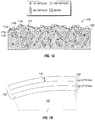
- Fig. 1A is a diagram of a portion of a layer 102 of a coating 100. While an outer surface 114 of layer 102 is apparent, Fig. 1 is not intended to depict an inner surface of layer 102 or underlying coating layers.
- underlying layers 104 and 106 of coating 100 are shown in Fig. 1B formed over substrate 108 and may have the same composition and exhibit the same structural features as layer 102.
- Layer 102 contains first particles substantially homogeneously distributed throughout a thickness 110 of the matrix.
- the matrix is shown in Figure 1A as a continuous matrix, which may be substantially fluorine-free and cross-linked.
- Thickness 110 of the matrix extends inward from a top periphery 112 of the matrix to a bottom periphery (not shown in detail in Figure 1A ) of the matrix.
- Layer 102 also contains second particles substantially homogeneously distributed throughout thickness 110 of the matrix.
- Layer 102 further contains third particles substantially homogeneously distributed throughout thickness 110 of the matrix.
- first, second, and third particles are not drawn to scale, but are intended to graphically depict approximate shapes and the feature that the third particles exhibit particle sizes greater than the second particles, which exhibit particle sizes greater than the first particles.
- the second particles may contain a fluoropolymer and may have a composition different from the third particles and the first particles. Additionally, the third particles may have a composition different from the first particles. Compositional differences are represented in Figure 1A with different hatching patterns for the matrix and the first, second, and third particles.
- the fluoropolymer herein may exist in discrete particles throughout the matrix, providing additional benefits beyond the mere hydrophobicity of fluoropolymer materials.
- Layer 102 includes an outer surface 114 with surfaces of at least first particles extending outward from top periphery 112 of the matrix.
- outer surface 114 includes surfaces of first particles 114a, matrix 114b, and second particles 114c.
- Surfaces of second particles 114c of outer surface 114 extend outward from top periphery 112c of the matrix.
- Surfaces of first particles 114a of outer surface 114 extend outward from top periphery 112a of the matrix.
- Surfaces of matrix 114b of outer surface 114 coincide with top periphery 112b of the matrix.
- outer surface 114 may exhibit a water contact angle greater than 90 degrees. (See Fig. 8 , blocks 828 and 806).
- Outer surface 114 may include surfaces of the first particles exhibiting a particle size range of less than about 100 nm, such as from about 5 nm to about 50 nm.
- outer surface 114 may exhibit a property of delaying ice formation compared to layer 102 without the first particles. Such properties may be afforded even in the circumstance where the matrix exhibits a water contact angle less than 90 degrees, including at surfaces of matrix 114b of outer surface 114.
- the polarity (or hydrophobicity) of particles may also contribute to delaying ice formation. Less polar (more hydrophobic) particles may delay ice formation since ice is polar and formation on a non-polar or less polar surface is energetically less favorable.
- Less polar (more hydrophobic) particles may delay ice formation since ice is polar and formation on a non-polar or less polar surface is energetically less favorable.
- Layer 102 may exhibit a cured porosity of at most 70 vol%, such as at most 25 vol%. Porosity may be present as voids (not shown) in the matrix.
- the first particles may form a Pickering emulsion with voids.
- Such an emulsion may include two phases having an interface therebetween, for example, an air-liquid interface, a hydrophilic-hydrophobic interface, etc. Solid particles, which adsorb onto the phase interface, may stabilize the emulsion.
- small droplets of oil may form throughout the water initially, but later recombine to reduce the energy of the mixture.
- solid particles added to the mixture may bind to the surface of the droplet's oil/water interface and stabilize the emulsion by making the combination of oil droplets less energetically favorable. Particle size, shape, and hydrophobicity may further affect stability. In this sense, the particles behave as a "surfactant.”
- Voids dispersed throughout the matrix of layer 102 provide an air-liquid interface to which the first particles may adsorb. Accordingly, uniformly distributed voids may assist in uniformly distributing first particles. While porosity resulting from voids in the matrix may assist in distributing first particles, too much porosity reduces strength and increases water penetration of coating 100. For such reason, some porosity may be desirable, such as, from at least 5 vol% to at most 25 vol%.
- first particles may then adsorb onto the interface between a less hydrophobic matrix and a more hydrophobic particle that is larger than first particles. Since the coating described herein includes use of a hydrophilic polymer matrix and second and third particles may be treated to increase hydrophobicity, hydrophilic-hydrophobic interfaces may exist which are dispersed throughout the matrix. The dispersed interfaces further assist in uniformly distributing first particles.
- first particles such as silica
- first particles may coat the second particles as a surfactant to reduce flocculation of the second particles, such as by forming a Pickering emulsion.
- Top periphery 112 of the matrix may also present an air-liquid interface to which first particles may migrate.
- first particles may act as a surfactant, adsorbing to the interface.
- Such behavior provides first particles extending outward from top periphery 112 of the matrix.
- First particles are both adsorbed to the cured matrix and exposed as part of outer surface 114 of layer 102. (See Fig. 8 , blocks 830 and 834).
- Second particles exhibiting a hydrophobicity difference from the matrix and a particle size range from about 100 nm to about 500 nm may also migrate to top periphery 112. Second particles may then also be adsorbed to the cured matrix and extend outward from top periphery 112 to be exposed as part of outer surface 114. (See Fig. 8 , blocks 828 and 806).
- third particles In addition to first particles stabilizing second particles in the matrix as an emulsion, observation indicated that third particles also contributed to substantially homogeneously distributing second particles in the matrix. Second particles may be too large to form a Pickering emulsion with the much larger third particles. Also, polytetrafluoroethylene second particles likely will not preferentially go into either a water or oil phase. That is, while they are hydrophobic, they might also be lipophobic and/or oleophobic. Without the presence of third particles, second particles were observed to separate from the matrix liquid phase during mixing by jar milling. Without being limited to any particular theory, suitable third particles may act as a flow reducer and thickener in a coating composition.
- the high aspect ratio of needle-shaped, acicular, cylindrical, or similar particles may produce a viscosity increase and screen migration of particles in the liquid phase of a coating composition. Accordingly, third particles might assist in reducing agglomeration of second particles and in keeping them dispersed. (See Fig. 8 , blocks 814 and 820).
- Respective substantially homogeneous distribution of first, second, and third particles throughout the matrix may provide the benefit of preserving hydrophobic and icephobic properties of outer surface 114.
- the properties may remain at least to some extent.
- Erosion of layer 102 may remove portions of outer surface 114, including first particles and second particles, exposing underlying matrix and other first particles and second particles. Removal of particles and the matrix tends to occur at the weakest points in layer 102, namely at matrix-void interfaces and matrix-particle interfaces. As a result, since first particles may be adsorbed at void interfaces, erosion tends to expose particles underlying outer surface 114 that migrated to the air-liquid interface of voids.
- a method includes applying a coating composition in one application step.
- the one-step coating composition contains first particles, second particles, and third particles in a base containing a polymer.
- the second particles have a composition different from the third particles and first particles and the third particles have a composition different from the first particles.
- the method includes curing the applied one-step coating composition, forming a cross-linked, continuous polymer matrix, and forming a layer of a cured coating.
- First particles are substantially homogeneously distributed throughout a thickness of the cross-linked, continuous polymer matrix, the thickness of the polymer matrix extending inward from a top periphery of the polymer matrix to a bottom periphery of the polymer matrix.
- Second particles are substantially homogeneously distributed throughout the thickness of the polymer matrix.
- Third particles are substantially homogeneously distributed throughout the thickness of the polymer matrix.
- the method includes forming an outer surface of the cured layer including at least first particles extending outward from the top periphery of the polymer matrix. The outer surface exhibits a water contact angle greater than 90° and exhibits a property of delaying ice formation compared to the cured layer without the first particles.
- one-step application is another benefit.
- Some prior art forms multiple layers of differing composition to complete a coating or treat a coating after application to imbue certain properties.
- materials of coating compositions herein inherently possess desired properties in their as-applied state without further layers, treatment, etc. Curing merely solidifies the structural features.
- the cured layer may exhibit a porosity of at most 25 vol%.
- the cured layer may be formed over an exterior surface of an aircraft.
- the method may further include forming a plurality of the layers of the cured coating by repeating the application of the coating composition over the exterior surface and curing the repeatedly applied one-step coating composition.
- the second particles may contain a fluoropolymer and the polymer matrix may be substantially fluorine-free.
- the particles may exhibit the size ranges described elsewhere herein.
- the outer surface may exhibit the surface roughness described elsewhere herein.
- Applying the coating composition may include spray applying using known techniques. Known paint on methods or appliques may be used instead, though a benefit exists in compatibility with known spray equipment for efficient coverage of large areas.
- Curing the coating composition may include completing the cross-linking or completing the cross-linking sufficiently for the intended use of the coating.
- the polymer matrix may exhibit a water contact angle less than 90° and the outer surface of the cured layer may further comprise polymer matrix.
- the second particles may be selected to exhibit the property of reducing water infiltration compared to an equal mass of the first particles, third particles, or a combination thereof. Eroding the outer surface forms another outer surface, the other outer surface exhibiting a water contact angle greater than 90° and a property of delaying ice formation compared to the cured layer without the first particles.
- a coating composition includes first particles, second particles, and third particles distributed in a matrix precursor containing a polymerizable species and, optionally, a solvent.
- the second particles contain polytetrafluoroethylene and exhibit a particle size range of from about 100 nm to about 500 nm.
- the first particles are hydrophobic and contain a material selected from the group consisting of silica, carbon, graphite, fluoropolymers, alumina, ceria, zirconia, titania, zinc oxide, and combinations thereof and exhibit a particle size range of less than about 100 nm.
- the third particles contain a material selected from the group consisting of calcium silicate, calcium carbonate, iron oxides, Fe 2 O 3 , Fe 3 O 4 , FeOOH, and combinations thereof.
- the third particles also exhibit a particle size range for their largest dimension of greater than about 250 nm and further stabilize dispersion of the second particles compared to the coating composition without the third particles.
- the first particles may reduce flocculation of the second particles and stabilize dispersion of the second particles.
- the first particles may form a Pickering emulsion with the second particles.
- the matrix precursor may be substantially fluorine-free.
- the first particles may contain SiO 2 and exhibit a particle size range of from about 5 nm to about 50 nm.
- the third particles may contain CaSiO 3 and exhibit a particle size range for their largest dimension of greater than about 500 nm to about 20,000 nm.
- the matrix precursor may meet qualification requirements in accordance with an aerospace specification.
- the coating composition may exhibit a mass ratio of B:1st:2nd:3rd, wherein "B” is the proportion of solids in the matrix precursor and "1st,” “2nd,” and “3rd” are the respective proportions of first, second, and third particles, B being less than the sum of 1st, 2nd, and 3rd and 2nd being greater than both 1st and 3rd.
- samples using Akzo Nobel ECL-G-7 with 1:1:4:2 mass ratio such as samples 126 and 137, they were made as follows: Silica (2g), TEFLON (8g), CaCO 3 or CaSiO 3 (4g), and Akzo Nobel TR-109 Thinner (22g) were added to a 50 mL centrifuge tube then briefly vortexed to homogenize the mixture.
- the mixture was then weighed and mixed for 15 minutes with a planetary centrifugal mixer available from THINKY USA, Inc. in Madison Hills, California. The mixture was weighed again and solvent was added to restore the original mass.
- Coupons painted with an aerospace white topcoat (PPG DESOTHANE CA8000 BAC70846 white) as control specimens were prepared by spraying with Sur-Prep AP-1 adhesion promoter manufactured by AndPak, Inc. in Morgan Hill, California and allowed to dry for 30 minutes. Then the paint mixture was placed in a DeVilbiss (in Glendale Heights, Illinois) gravity spray gun and applied using an air pressure of 10 pounds per inch 2 (psi) on the coupons. The painted coupons were left in a fume hood for at least 10 hours and then either cured in an 80 oC oven for 4 hours or a 50 °C oven for 16 hours.
- PPG DESOTHANE CA8000 BAC70846 white as control specimens
- PPG DESOTHANE CA8800/B900 is a two-part polyurethane aerospace clear-coat paint.
- Akzo Nobel ECLIPSE ECL-G-7 is a two-part polyurethane aerospace clear-coat paint.
- Hexamethyldisilazane (HMDZ) treated silica nanoparticles are 22 nm in diameter and were used to inhibit icing.
- the particle diameter is similar to the size of ice nuclei and is believed to disrupt them.
- Particles of about this size are theorized to reduce the nucleation rate of ice based on both their hydrophobic character and the high curvature forced on the ice nuclei during heterogeneous nucleation on the particle surface. (See, Conrad, P.; Ewing, G. E.; Karlinsey, R. L.; Sadtchenko, V. J. Chem. Phys. 2005, 122, 064709 ).
- Heterogeneous nucleation refers to nucleation on a surface other than ice, while homogeneous nucleation refers to nucleation on ice already formed.
- the HMDZ treated silica nanoparticles were easily incorporated into the DESOTHANE clear coat system. Polymer solids-to-silica mass ratios of 1:1, 2:1, and 4:2 were used in experiments because these ratios were found to increase inhibition of ice nucleation without coating embrittlement in preliminary testing.
- BYK LP-X22325 (formerly LP-X21261) is a hydrophobic colloidal silica with an average particle size of 20 nm.
- SUPER-PFLEX 100 CaCO 3 available from Specialty Minerals in Bethlehem, Pennsylvania is a star shaped, stearate modified (1 weight percent (wt%)), hydrophobic filler that creates surface roughness through porosity. Coatings based on this material were favored in preliminary testing but were supplanted by more durable coatings containing Wollastonite. The SUPER-PFLEX material was utilized in one of the preferred coatings.
- SUPER-PFLEX 200 CaCO 3 is a star shaped, stearate modified (2wt%), hydrophobic filler that creates surface roughness through porosity. This coating has a stearate density twice as high as SUPER-PFLEX 100. Coatings based on this material were not superior to SUPER-PFLEX 100 based coatings and were not preferred.
- Wollastonite CaSiO 3 are needle-shaped particles less than 10 micrometer ( ⁇ m) in length available from NYCO Minerals Inc. in Willsboro, New York in three variants that have the same size and aspect ratio. CaSiO 3 is attractive because of the variety of morphologies, surface treatments, and robustness against degradation from exposure to acids, bases, or solvents.
- Wollastonite 1250WC (NYCO Minerals M1250 Wollastocoat 20804) is surface modified with hydrophobic surface groups to control polarity and amine groups that chemically bond with isocyanates used in polyurethanes. 1250WC material was in the highest performing coatings.
- Wollastonite 1250AS (NYCO Minerals M1250 AS Wollastocoat) is surface modified with amine groups that chemically bond with isocyanates used in polyurethanes. Coatings containing this filler had slightly shorter ice nucleation delays than coatings containing 1250WC, probably because of their more hydrophilic nature. Wollastonite 1250 is particles without any surface modification. These particles do not resist water infiltration after multiple freezing cycles and were not used in preferred coatings.
- Wollastonite Aspect 3000 WC20804 is a CaSiO 3 particulate filler with a higher aspect ratio than Wollastonite 1250WC. It has an average particle size of 7 microns and a surface area of 2.2 meter 2 /g. This material is coated with amine and hydrophobic chemical groups.
- TEFLON R
- ZONYL R
- MP 1000 nanoparticles are 200-300 nm in diameter and were added to the coatings to maintain surface roughness while decreasing water infiltration.
- TEFLON was used in preferred coatings with a 1:1:4:2, 2:1:4:2, or 4:2:4:2 (polyurethane: silica: TEFLON: (Wollastonite or CaCO 3 )) solids mass ratio.
- the mixing of the formulations was increased to homogenize throughout the coating the distribution of fillers that affect icing.
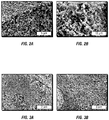
- the fillers were first combined with solvent, jar milled for 3 to 12 hours to disperse them in the solvent, mixed with polyurethane coating material, and mixed in a Thinky centrifugal mixer. The end result was a more uniform top surface as shown in Figs. 3A and 3B .
- Top SEM images of coatings without ( Fig. 3A ) and after ( Fig. 3B ) premixing of fillers in a jar mill followed by Thinky mixing of the formulation were produced. Increased mixing of the formulation resulted in more uniformly distributed TEFLON and silica at the surface as well as longer freezing delays.
- the -5 oC freezing delay for first observation of ice from a 1:1:2:4 DESOTHANE polyurethane: silica: TEFLON: SUPER-PFLEX 100 CaCO 3 (solids mass ratio) coating increased to almost 300 seconds from 100 seconds as a result of more mixing. However, after abrasion, the freezing delay decreased to 30 seconds over three freezing cycles. Reduction in freezing delay after abrasion was also observed for coatings based on Wollastonite fillers. SEM showed there still were significantly reduced amounts of TEFLON and silica in the body of the coatings.
- Fig. 4 shows -5 oC freezing delays for initial observation of ice from multiple freezing cycles for coatings containing different silica nanoparticles, TEFLON nanoparticles, and SUPER-PFLEX 100 CaCO 3 in a 1:1:2:4 DESOTHANE polyurethane: silica: TEFLON: SUPER-PFLEX 100 CaCO 3 solids weight ratio.
- the type of silica is shown in the legend. The coatings showed a significant decrease in freezing delay after abrasion.
- Samples 162, 163, 167, and 168 were prepared with a greater mass fraction of polymer (4 polymer: 2 silica: 4 TEFLON: 2 CaSiO 3 mass ratio) and evaluated. Performance results, including freezing delay pre- and post-abrasion, are shown in Table 1. Fig. 7 shows freezing point delay through three freeze cycles for both pre- and post-abraded samples.
- the sample was prepared by spraying the coating onto glass, scraping the coating off the glass, and then analyzing the scraped-off coating. As the pore size cutoff increases, spacing between portions of the scraped-off coating might be included in the measured value. Accordingly, actual porosity of the coating itself may be lower.
- sample 212 was prepared with identical composition except that TEFLON was replaced with additional CaSiO 3 of equal mass. That is, it contained 4:2:0:6 solids mass ratio of DESOTHANE polyurethane: hexamethyldisilazane SiO 2 : TEFLON: Wollastonite 1250WC.
- the porosity determination sample was prepared by spraying the coating onto glass, scraping the coating off the glass, and then analyzing the scraped-off coating. As the pore size cutoff increases, spacing between portions of the scraped-off coating might be included in the measured value. Accordingly, actual porosity of the coating itself may be lower.
- sample 162 which contained TEFLON maintained the freezing delays over three cycles.
- Sample 162 had freezing delays at -5° C of (1st, 2nd, 3rd freezing cycle): 401 +/- 46 sec, 427 +/- 28 sec, 383 +/- 39 sec.
- Sample 212 had freezing delays at -5° C of (1st, 2nd, 3rd freezing cycle): 363 +/- 84 sec, 48 +/- 9 sec, 86 +/-3 sec.
- TEFLON being more hydrophobic than the silica and Wollastonite was believed to be the cause. If TEFLON lines the pores of sample 162, capillary pressure may be greater against infiltration and less water may seep in compared to sample 212. Even if there are more pores or a greater pore volume, water could have a greater capillary pressure to overcome to enter the TEFLON lined pores. Capillary pressure pulls water into pores lined with hydrophilic materials and pushes water out of pores lined with hydrophobic materials. Consequently, TEFLON particles exposed within pores may reduce water infiltration into pores.
- PPG is DESOTHANE HS CA8800/B900 polyurethane clear coat
- AN is Akzo Nobel ECLIPSE G-7 polyurethane clear coat
- S100 is SUPER-PFLEX 100 CaCO 3 (calcium carbonate)
- S200 is SUPER-PFLEX 200 CaCO 3
- WC is Wollastonite 1250WC
- AS is Wollastonite 1250AS
- 1250 is Wollastonite 1250
- A3000 is Wollastonite Aspect 3000 WC20804
- HMDZ silica is Hexamethyldisilazane SiO 2
- BYK is BYK LP-X21261 hydrophobic colloidal silica.
- a topcoat sample has an initial freezing delay at -5 oC of ⁇ 30 seconds before abrasion and ⁇ 10 seconds after abrasion.
- "Pins” indicates failure of a 50 ⁇ L water droplet to roll as the surface was tilted to 90o. Some coatings have missing measurements because they were not suitable for further evaluation based on initial results.
- Coatings containing Wollastonite 1250 did not maintain sufficient freezing delays for water with multiple freezing cycles. This was probably due to the hydrophilic surface.
- ECLIPSE polyurethane mixed with HMDZ silica, TEFLON, and SUPER-PFLEX CaCO 3 showed moderately increased contact angles, increased maintenance of freezing delays pre- and post-abrasion, and increased hardness compared to coatings with the same mass ratio and silica type containing Wollastonite 1250WC.
- Sample 126 had a higher hardness rating compared to 135 and was used for testing shown in Fig. 5 .
- Samples containing a 2:1:4:2 polyurethane: silica: TEFLON: Wollastonite 1250WC solids mass ratio had increased hardness as well as ice nucleation inhibition pre- and post-abrasion after multiple cycles compared to coatings with less polymer, i.e. 1:1:4:2 mass ratio coatings.
- Sample 139 had an increased contact angle. Both samples 139 and 140 were used for testing shown in Fig. 5 .
- Samples containing a 4:2:4:2 polyurethane: silica: TEFLON: Wollastonite 1250WC or A3000 increased the mass fraction of polymer in the coatings compared to coatings with less polymer, i.e. 1:1:4:2 or 2:1:4:2. The greater amount of polymer was shown to increase damage tolerance. Also, ice nucleation inhibition increased for pre- and post-abrasion after multiple cycles.
- Samples based on Wollastonite 1250AS had increased hardness, contact angles, and freezing delays compared to coatings with the same mass ratio and silica type that contain Wollastonite 1250WC.
- Sample 130 was used for testing shown in Fig. 5 because it was one of the two better samples based on DESOTHANE.
- the pre- and post-abrasion -5 oC freezing delays to the time for first observation of 3 to 5 droplets of ice for three freezing cycles are shown in Fig. 5 for samples 126, 130, 137, 139, and 140.
- the samples performed better than pre- and post-abraded aircraft white topcoat (PPG DESOTHANE HS CA8000 BAC 70846 white).
- Fig. 7 shows time until initial observation of ice at -5 oC for the higher polymer mass fraction samples of Table 1.
- the samples went through three freezing cycles as indicated by the legend on the graph.
- the times until freezing for the as-made and abraded samples with a 4:2:4:2 solids mass ratio were significantly longer than the times for lower polymer content samples in Fig. 5 .
- the hardness of the higher polymer mass fraction samples was greater than the lower polymer mass fraction samples, which may result in a more durable coating.
- the present invention is defined by method claims 1 to 16 and curable coating composition claims 17 to 20.
Description
- The present application claims the benefit of priority under 35 U.S.C. § 1 19 to
U.S. Provisional App. No. 61/838,605, filed June 24, 2013 14/058,470 filed 21 Oct 2013 US 2015/044420 A1 and granted underUS 9,637,658 B2 EP14796566.9 PCT/US2014/034889 published underWO 2015/012910 A2 . - Compositions and methods herein pertain to coatings, coating compositions, and methods, including those related to delaying ice formation, such as in aerospace applications.
-
DE 199 44 169 A1 discloses a method for producing self-cleaning surface coatings, whereby a coating agent dispersion or solution is applied with a thin coat to the surface and is dried thereon. Said coating agent dispersion or solution is comprised of: - a) a film-forming plastic provided in the form of an aqueous dispersion or of a solution in an organic solvent,
- b) a hydrophobic polymer provided in the form of a powder with an average grain size ranging from 10-50 µm which is insoluble in the above-mentioned solvent,
- c) a sufficient quantity of water and/or of an organic solvent for producing a coating agent that is capable of being spread or sprayed,
- d) whereby the applied layer is so thin that the grains of the hydrophobic polymeric powder are interspaced by a distance of 5 to 100 µm, and
- e) whereby the quantity of the film-forming plastic is measured so that it forms a layer after the solvent evaporates whose thickness is equal to 30-60 % of the average grain size of the hydrophobic powder.
- Accumulation of frost, ice, or snow on aircraft changes airflow over aircraft wings, reducing lift and increasing drag. The accumulations also add to the total weight, increasing lift required for takeoff. Accordingly, frost, ice, or snow is normally removed prior to take-off. While in flight, hot engine bleed air, electric blankets, mechanical boots, or combinations thereof may be used to keep ice off exterior surfaces of aircraft. Unmanned Aerial Vehicles (UAV) and rotorcraft cannot operate at certain altitudes due to potential icing of flight surfaces. The listed measures actively consume energy, add weight, and reduce fuel economy.
- On the ground, anti-icing and de-icing fluids in the form of hot glycol sprays are employed. While effective, such fluids generate an added expense and may cause gate delays from additional application time. The glycol fluids may generate added expense for remediation. As a result, different options for removing ice from aircraft are desirable.
- In one aspect, there is provided a coating including at least one coating layer containing first particles substantially homogeneously distributed throughout a thickness of a cross-linked, continuous polymer matrix. The thickness of the polymer matrix extends inward from a top periphery of the polymer matrix to a bottom periphery of the polymer matrix. The coating layer also contains second particles substantially homogeneously distributed throughout the thickness of the polymer matrix. The coating layer further contains third particles substantially homogeneously distributed throughout the thickness of the polymer matrix. The second particles have a composition different from the third particles and first particles. An outer surface of the at least one coating layer includes surfaces of at least first particles extending outward from the top periphery of the polymer matrix. The outer surface exhibits a water contact angle greater than 90° and exhibits a property of delaying ice formation compared to the coating layer without the first particles.
- In another aspect, there is provided a method including applying a coating composition in one application step. The one-step coating composition contains first particles, second particles, and third particles in a base containing a polymer. The second particles have a composition different from the third particles and first particles and the third particles having a composition different from the first particles. The method includes curing the applied one-step coating composition, forming a cross-linked, continuous polymer matrix, and forming a layer of a cured coating. First particles are substantially homogeneously distributed throughout a thickness of the cross-linked, continuous polymer matrix, the thickness of the polymer matrix extending inward from a top periphery of the polymer matrix to a bottom periphery of the polymer matrix. Second particles are substantially homogeneously distributed throughout the thickness of the polymer matrix. Third particles are substantially homogeneously distributed throughout the thickness of the polymer matrix. Also, the method includes forming an outer surface of the cured layer including at least first particles extending outward from the top periphery of the polymer matrix. The outer surface exhibits a water contact angle greater than 90° and exhibits a property of delaying ice formation compared to the cured layer without the first particles.
- In a further aspect, there is provided a coating composition including first particles, second particles, and third particles distributed in a matrix precursor. The second particles contain polytetrafluoroethylene and exhibit a particle size range of from about 100 nm to about 500 nm. The first particles are hydrophobic and contain a material selected from the group consisting of silica, carbon, graphite, fluoropolymers, alumina, ceria, zirconia, titania, zinc oxide, and combinations thereof and exhibit a particle size range of less than about 100 nm. The third particles contain a material selected from the group consisting of calcium silicate, calcium carbonate, iron oxides, Fe2O3, Fe3O, FeOOH, and combinations thereof. The third particles also exhibit a particle size range for their largest dimension of greater than about 250 nm and further stabilize dispersion of the second particles compared to the coating composition without the third particles.
- The features, functions, and advantages that have been discussed can be achieved independently in various embodiments or may be combined in yet other embodiments further details of which can be seen with reference to the following description and drawings.
- Some aspects are described below with reference to the following accompanying drawings.
-
Fig. 1 is a diagram of an icephobic coating with particles substantially homogeneously distributed in a matrix. -
Figs. 2 and 3 are coating micrographs taken by a scanning electron microscope (SEM). -
Figs. 4-7 are charts of freezing delay for various evaluated coating samples. -
Fig. 8 is a functional block diagram summarizing some of the relationships described in further detail herein. - The ice reduction measures disclosed herein do not actively consume energy and are not single-use applications of materials that also use energy for each application. Materials described herein do not use external energy during operation, avoid the use of glycol ethers, and provide ice delays over multiple freeze cycles. Consequently, the methods and materials herein may increase aircraft fuel efficiency, reduce use of deicing fluids and their environmental impact, reduce inflight energy consumption used for ice removal, etc. Although discussed in the context of aviation use, other possible uses are contemplated, such as on wind turbine blades, in non-aerospace transportation, and in communications, including on satellite dishes. The material may be formulated as a coating, such as a paint.
- Materials described herein are thus passive coatings that use no external input of energy to delay ice formation and retain their efficacy after multiple freeze cycles. Some known coatings purport to possess similar benefits. Even so, none provide the herein described level of dewetting and freezing delay combined with toughness and durability. The exterior environment associated with aircraft and other transportation applications (such as, automotive applications) over extended periods may be harsh. Methods and materials herein provide a coating with a cross-linked polymer matrix for toughness and durability. (See
Fig. 8 ,blocks 812 and 802). Also, porous voids and surface roughness of the coating exist on a length scale of hundreds of nanometers to inhibit the wetting of water. (SeeFig. 8 , blocks 826 and 806). Further, a layer of nanoparticles at the coating surface inhibits nucleation of ice. (SeeFig. 8 , blocks 834 and 808). Additionally, structural features substantially homogeneously distributed across the coating thickness present similar performance initially and following erosion, defined as removing part of the coating, including abrasion and other forms of wear. (SeeFig. 8 , blocks 820 and 804). - Known coatings may involve a porous foam network created by extraction of colloidal templates to produce some of the benefits indicated above. As used herein, a "templating material" or "template" refers to a discrete particle that affects the shape of the polymer surrounding it. A templating material, such as solid particles, may be dispersed in a continuous matrix. The matrix acquires a structure around the templating material and the structure remains after extraction of the templating material. Previously, intentional removal of templates was viewed as a prerequisite to creating a sufficient amount of air/water interface to achieve high contact angles and dewetting. The methods and materials herein do not necessarily involve removal of templating material, but still achieve high dewetting performance. Observation herein surprisingly indicated that the surface roughness and voids that drive high contact angle dewetting behavior may be created instead through selection of certain template morphologies, even when the templating material remains in the matrix. (See
Fig. 8 , blocks 816, 824, 832, and 826). Additionally, it was surprising that a polymer matrix around solid particles formed voids rather than coating the particles fully. - A coating includes at least one coating layer containing first particles substantially homogeneously distributed throughout a thickness of a cross-linked, continuous polymer matrix. The thickness of the polymer matrix extends inward from a top periphery of the polymer matrix to a bottom periphery of the polymer matrix. The coating layer also contains second particles substantially homogeneously distributed throughout the thickness of the polymer matrix. The coating layer further contains third particles substantially homogeneously distributed throughout the thickness of the polymer matrix. The second particles have a composition different from the third particles and first particles. An outer surface of the at least one coating layer includes surfaces of at least first particles extending outward from the top periphery of the polymer matrix. The outer surface exhibits a water contact angle greater than 90° and exhibits a property of delaying ice formation compared to the coating layer without the first particles.
- By way of example, the second particles may contain a fluoropolymer. The polymer matrix may be substantially fluorine-free. A "substantially" fluorine-free continuous polymer matrix refers to some trace amounts of fluorine that may be present in the polymer. For example, fluorine might not be a primary component of the polymer chain itself, but nonetheless part of the polymer as a catalyst residue, contaminant, etc. Additionally, the polymer matrix need not incorporate exotic fluorine polymers, such as fluorinated polyhedral oligomeric silsesquioxanes, that are costly and difficult to manufacture. Known polyhedral oligomeric silsesquioxanes are available under the trade name POSS from Hybrid Plastics, Inc. of Hattiesburg, Maryland. A substantially fluorine-free continuous polymer matrix may still allow the benefits arising from a completely fluorine-free matrix, which include more choice in selection of a polymer, no requirement of polymer fluorination measures, and, thus, simplified coating application procedures. The first particles may also be substantially fluorine-free, which refers to some trace amounts of fluorine that may be present. A substantially fluorine-free first particle may still allow the benefits arising from a completely fluorine-free first particle.
- "Substantially" homogeneously distributed particles refers to some deviation from a perfect distribution that may occur and still provide the properties of water contact angle and delays in ice formation. Since the coating could be formed over an underlying substrate, the "outer surface" of the coating layer refers to a surface of the coating layer outward or away from the substrate while the "inner surface" refers to a surface of the coating layer inward or toward the substrate. A homogeneous distribution is a distribution with a uniform structure or composition; for example, a uniform pattern of distributed particles.
- The uniform pattern may be single particles spaced equally, multiple groupings of particles with the groupings spaced equally, or some other pattern. A substantially homogeneous distribution of each of first particles, second particles, and third particles is shown in
Fig. 1 . Notably, all of the first particles are not equally spaced, but they are arranged in a substantially uniform pattern and are thus substantially homogeneously distributed. Since "each" of the three different types of particles is substantially homogeneously distributed, the first particles are individually substantially homogeneously distributed, as are the second and third particles, each type in its own substantially uniform pattern. Given the different size scales and other factors (as discussed further below), some migration together of the first particles with the second particles is shown, but does not upset the individual distribution of each of the three types of particles in their own respective substantially uniform pattern. Indeed, such migration may promote homogeneity (see below). - The coating may be formed from damage-tolerant layers including the cross-linked, polymer matrix with exposed nanoparticles that delay the nucleation of ice. The coating may retain its properties after erosion, such as by abrasion or impacts, and may be sufficiently tough to survive rain erosion from collision with raindrops. The coatings may be formed using a templating process wherein a matrix precursor or liquid base is mixed with templating colloids and nanoparticles, the mixture applied to a surface, and the matrix precursor cured.
- Possible polymers include polyurethanes, polyfluorourethanes, epoxies, carbamates, and polysiloxanes that may be cross-linked in the matrix. The coating may be created from aerospace qualified materials that pass durability testing to allow effective use on aircraft. Examples of matrix precursors include DESOTHANE (R) HS CA8800/B900 available from PPG Aerospace in Sylmar, California and ECLIPSE (R) (ECL-G-7) available from Akzo Nobel Aerospace Coatings in Waukegan, Illinois, both of which are solvent borne gloss polyurethane clear coats. The matrix precursor may contain a polymerizable species and, optionally, a solvent.
- Aerospace qualified materials are often resistant to ultraviolet (UV) radiation, as is aliphatic urethane, instead of aromatic urethane, which is not UV resistant. Aerospace qualified materials may be resistant to common materials encountered in aerospace applications, such as hydraulic fluid. While some aerospace qualified materials may be beneficial in an exterior application on aircraft, other aerospace qualified materials may only be qualified for an interior application on aircraft, such as polysiloxane and carbamate polymers. Interior polymers might not be exposed to UV radiation or hydraulic fluid, but still help delay ice accumulation, such as interior condensation in the form of frost on airplane structures. Rapidly melting frost can create nuisance moisture in an airplane cabin. One benefit of at least some of the materials used in the coatings herein includes their compatibility with some known, aerospace qualified matrix precursors so that re-formulation is unnecessary.
- The precursor solution may include solvents that do not adversely react in formation of the cross-linked network or dissolve/swell the templating particles. Examples include water, alcohols (such as, methanol, ethanol, isopropanol, t-butanol), acetone, ketones (such as, methyl ethyl ketone, methyl isobutyl ketone, and methyl amyl ketone), toluene, and t-butyl acetate. A colorant and other additives may be included in the precursor solution.
- Templating materials may create roughness in the polymer matrix without removal of the materials. (See
Fig. 8 , blocks 824, 832, and 826). Templating materials may have an inorganic composition, such as, CaSiO3 (calcium silicate), CaCO3 (calcium carbonate), or iron oxides (such as, Fe2O3, Fe3O4, FeOOH). Furthermore, acicular CaCO3 particles or needle-shaped Wollastonite (CaSiO3) particles may be used. Wollastonite is a calcium silicate mineral that may contain trace amounts of other elements. Iron oxides, Fe2O3, Fe3O4, and FeOOH may also be acicular. - TEFLON (R) polytetrafluoroethylene (PTFE) may be included as another templating material, such as, mixtures of 100-500 nanometer (nm) TEFLON particles with the templating materials listed above. DUPONT (TM) TEFLON (R) ZONYL (R) MP 1000 nanoparticles with 200-300 nm diameter are suitable.
TEFLON 200 nm particles have been used to induce roughness. (SeeFig. 8 , blocks 816 and 826). Observation indicated that the TEFLON particles reduce water infiltration of a coating as compared to coatings without TEFLON. (SeeFig. 8 , blocks 816 and 818). The reduction in water infiltration increases durability and increases delay in ice formation compared to coatings without TEFLON. (SeeFig. 8 , blocks 818 and 802). However, observation further indicated that using only TEFLON, without other listed templating materials, did not yield a substantially uniform distribution of the TEFLON. (SeeFig. 8 , blocks 828 and 820). CaCO3 or Wollastonite bears the effect of substantially uniformly distributing TEFLON in a coating composition and, thus, the resulting coating. When no CaCO3 or Wollastonite was used, the TEFLON phase separated during jar milling. - Templating materials may undergo a surface treatment to increase hydrophobicity prior to incorporation in a coating composition. Possible surface treatments include alkylsilanes, fluoroalkylsilanes, phosphonic acids, and carboxylic acids, including fatty acids.
- Additional particles in the form of hydrophobic nanoparticles may be in the coating composition. Possible nanoparticles include silica, carbon, graphite, fluoropolymers, alumina, ceria, zirconia, titania, and zinc oxide. Like the templating materials, the nanoparticles may undergo a surface treatment to increase hydrophobicity prior to incorporation in the coating composition. Possible surface treatments are alkylsilanes and fluoroalkylsilanes. Hydrophobic silica nanoparticles of about 20 nm in size have been observed to inhibit ice nucleation.
- As may be appreciated, a variety of examples are contemplated for implementing the coating introduced above. The third particles may have a composition different from the first particles. Consequently, the first particles may contain SiO2 and the third particles may contain CaSiO3. The fluoropolymer may contain polytetrafluoroethylene. The third particles may exhibit particle sizes greater than the second particles, which may exhibit particle sizes greater than the first particles. The relevant particle sizes may be the values determined according to known standards for testing and measurement of particle sizes appropriate for the size range and composition of the particles.
- In more detail, the third particles may exhibit a particle size range for their largest dimension of greater than about 250 nm, such as greater than about 500 nm, including greater than about 500 nm to about 20,000 nm. The third particles may have an anisotropic particle size so that the largest dimension is from about 2,000 nm to about 10,000 nm, such as from about 3,000 nm to about 6,000 nm. The smallest dimension may be from about 100 nm to about 2,000 nm, such as from about 400 nm to about 600 nm. Accordingly, third particles may exhibit aspect ratios of at least about 1.5:1, such as from about 1.5:1 to about 10:1.
- The second particles may exhibit a particle size range of from about 100 nm to about 10,000 nm, such as from about 100 nm to about 500 nm, including from about 200 nm to about 300 nm. The first particles may exhibit a particle size range of less than about 100 nm, such as less than about 50 nm, including from about 5 nm to about 50 nm, for example, from about 15 nm to about 30 nm. In the coating, the coating layer may exhibit a mass ratio of 1st:2nd:3rd, wherein "1st," "2nd," and "3rd" are the respective proportions of first, second, and third particles, 2nd being greater than both 1st and 3rd.
- The polymer in the coating need not be hydrophobic and/or icephobic for the coating to exhibit beneficial properties described herein. As a result, the polymer matrix may exhibit a water contact angle less than 90°. For the coating to nonetheless delay ice formation, the outer surface of the coating layer may include surfaces of at least first particles in addition to surfaces of polymer matrix. The outer surface may further include surfaces of second particles extending outward from the top periphery of the polymer matrix and, perhaps, even third particles.
- Exposure of the particles at the outer surface may thus provide the desired properties without a hydrophobic and/or icephobic polymer matrix. Less restriction on the properties of the polymer matrix allows greater flexibility in formulation. (See
Fig. 8 , blocks 836, 812, and 810). Consequently, the coating does not rely on a fluorinated polymer matrix to delay ice formation and the matrix may be substantially fluorine free, affording the benefits of a fluorine-free matrix described above. Because first particles, second particles, and third particles are each substantially homogeneously distributed in the polymer matrix, erosion, such as abrasion or other wear, of the outer surface to form another outer surface may preserve similar properties. The removed polymer matrix and particles merely reveal underlying particles that function similarly. - The coating may include a plurality of such coating layers, each with its own outer surface. The outer surface of underlying coating layers is not necessarily exposed since it may be covered by the inner surface of an overlying coating layer. The polymer matrix may include polyurethane or the polymer matrix may meet qualification requirements in accordance with an aerospace specification or both. The polymer matrix may meet qualification requirements in accordance with specifications for other applications, such as use on wind turbine blades.
- The second particles may exhibit the property of reducing water infiltration compared to an equal mass of the first particles, third particles, or a combination thereof. Water infiltration may be controlled by reducing porosity. The coating layer may exhibit a cured porosity of at most 70 volume percent (vol%), such as at most 25 vol%, including from about 5 vol% to 25 vol%. Allowing at least some porosity may provide distributed void interfaces, such as air-polymer interfaces, and promote nanoparticle distribution, as discussed further below. Interfaces between polymer and particles much larger than nanoparticles may also promote nanoparticle distribution, as discussed further below. Despite a porosity value of at most 25 vol%, the outer surface may exhibit a surface roughness on a length scale of from about 100 nm to about 5,000 nm (200 microinches), such as from about 100 nm to about 4,000 nm, as induced by the templating material.
-
Fig. 1A is a diagram of a portion of alayer 102 of acoating 100. While anouter surface 114 oflayer 102 is apparent,Fig. 1 is not intended to depict an inner surface oflayer 102 or underlying coating layers. Optional,underlying layers coating 100 are shown inFig. 1B formed oversubstrate 108 and may have the same composition and exhibit the same structural features aslayer 102.Layer 102 contains first particles substantially homogeneously distributed throughout athickness 110 of the matrix. The matrix is shown inFigure 1A as a continuous matrix, which may be substantially fluorine-free and cross-linked.Thickness 110 of the matrix extends inward from atop periphery 112 of the matrix to a bottom periphery (not shown in detail inFigure 1A ) of the matrix.Layer 102 also contains second particles substantially homogeneously distributed throughoutthickness 110 of the matrix.Layer 102 further contains third particles substantially homogeneously distributed throughoutthickness 110 of the matrix. - It will be appreciated that the first, second, and third particles are not drawn to scale, but are intended to graphically depict approximate shapes and the feature that the third particles exhibit particle sizes greater than the second particles, which exhibit particle sizes greater than the first particles. The second particles may contain a fluoropolymer and may have a composition different from the third particles and the first particles. Additionally, the third particles may have a composition different from the first particles. Compositional differences are represented in
Figure 1A with different hatching patterns for the matrix and the first, second, and third particles. As opposed to a known continuous layer of fluoropolymer in a coating, as in the prior art, the fluoropolymer herein may exist in discrete particles throughout the matrix, providing additional benefits beyond the mere hydrophobicity of fluoropolymer materials. -
Layer 102 includes anouter surface 114 with surfaces of at least first particles extending outward fromtop periphery 112 of the matrix. InFigure 1A ,outer surface 114 includes surfaces offirst particles 114a,matrix 114b, andsecond particles 114c. Surfaces ofsecond particles 114c ofouter surface 114 extend outward fromtop periphery 112c of the matrix. Surfaces offirst particles 114a ofouter surface 114 extend outward fromtop periphery 112a of the matrix. Surfaces ofmatrix 114b ofouter surface 114 coincide withtop periphery 112b of the matrix. - By virtue of the roughness of
outer surface 114 and the presence of hydrophobic first particles and second particles,outer surface 114 may exhibit a water contact angle greater than 90 degrees. (SeeFig. 8 , blocks 828 and 806).Outer surface 114 may include surfaces of the first particles exhibiting a particle size range of less than about 100 nm, such as from about 5 nm to about 50 nm. As a result,outer surface 114 may exhibit a property of delaying ice formation compared tolayer 102 without the first particles. Such properties may be afforded even in the circumstance where the matrix exhibits a water contact angle less than 90 degrees, including at surfaces ofmatrix 114b ofouter surface 114. - The polarity (or hydrophobicity) of particles may also contribute to delaying ice formation. Less polar (more hydrophobic) particles may delay ice formation since ice is polar and formation on a non-polar or less polar surface is energetically less favorable. (See, Conrad, P.; Ewing, G. E.; Karlinsey, R. L.; Sadtchenko, V. J. Chem. Phys. 2005, 122, 064709). The tendency of one surface to allow ice formation more readily compared to another surface has been attributed in some cases to a significantly larger contact angle for the hydrophobic surface. (See
Fig. 8 , blocks 806 and 808). -
Layer 102 may exhibit a cured porosity of at most 70 vol%, such as at most 25 vol%. Porosity may be present as voids (not shown) in the matrix. The first particles may form a Pickering emulsion with voids. Such an emulsion may include two phases having an interface therebetween, for example, an air-liquid interface, a hydrophilic-hydrophobic interface, etc. Solid particles, which adsorb onto the phase interface, may stabilize the emulsion. When oil and water are mixed, small droplets of oil may form throughout the water initially, but later recombine to reduce the energy of the mixture. However, solid particles added to the mixture may bind to the surface of the droplet's oil/water interface and stabilize the emulsion by making the combination of oil droplets less energetically favorable. Particle size, shape, and hydrophobicity may further affect stability. In this sense, the particles behave as a "surfactant." - Voids dispersed throughout the matrix of
layer 102 provide an air-liquid interface to which the first particles may adsorb. Accordingly, uniformly distributed voids may assist in uniformly distributing first particles. While porosity resulting from voids in the matrix may assist in distributing first particles, too much porosity reduces strength and increases water penetration ofcoating 100. For such reason, some porosity may be desirable, such as, from at least 5 vol% to at most 25 vol%. - When the matrix is less hydrophobic than second particles and/or third particles, or perhaps hydrophilic with a water contact angle less than 90º, another interface exists in
layer 102. First particles may then adsorb onto the interface between a less hydrophobic matrix and a more hydrophobic particle that is larger than first particles. Since the coating described herein includes use of a hydrophilic polymer matrix and second and third particles may be treated to increase hydrophobicity, hydrophilic-hydrophobic interfaces may exist which are dispersed throughout the matrix. The dispersed interfaces further assist in uniformly distributing first particles. In the case of TEFLON second particles in a polyurethane matrix, the surface polarity of second particles does not match well with the polyurethane, so first particles, such as silica, may coat the second particles as a surfactant to reduce flocculation of the second particles, such as by forming a Pickering emulsion. (SeeFig. 8 , blocks 830, 822, and 820). -
Top periphery 112 of the matrix may also present an air-liquid interface to which first particles may migrate. When a coating composition is applied and the air-liquid interface attop periphery 112 is created, first particles may act as a surfactant, adsorbing to the interface. Such behavior provides first particles extending outward fromtop periphery 112 of the matrix. First particles are both adsorbed to the cured matrix and exposed as part ofouter surface 114 oflayer 102. (SeeFig. 8 , blocks 830 and 834). Second particles exhibiting a hydrophobicity difference from the matrix and a particle size range from about 100 nm to about 500 nm may also migrate totop periphery 112. Second particles may then also be adsorbed to the cured matrix and extend outward fromtop periphery 112 to be exposed as part ofouter surface 114. (SeeFig. 8 , blocks 828 and 806). - In addition to first particles stabilizing second particles in the matrix as an emulsion, observation indicated that third particles also contributed to substantially homogeneously distributing second particles in the matrix. Second particles may be too large to form a Pickering emulsion with the much larger third particles. Also, polytetrafluoroethylene second particles likely will not preferentially go into either a water or oil phase. That is, while they are hydrophobic, they might also be lipophobic and/or oleophobic. Without the presence of third particles, second particles were observed to separate from the matrix liquid phase during mixing by jar milling. Without being limited to any particular theory, suitable third particles may act as a flow reducer and thickener in a coating composition. The high aspect ratio of needle-shaped, acicular, cylindrical, or similar particles may produce a viscosity increase and screen migration of particles in the liquid phase of a coating composition. Accordingly, third particles might assist in reducing agglomeration of second particles and in keeping them dispersed. (See
Fig. 8 , blocks 814 and 820). - Respective substantially homogeneous distribution of first, second, and third particles throughout the matrix may provide the benefit of preserving hydrophobic and icephobic properties of
outer surface 114. When first particles and second particles are removed fromouter surface 114, the properties may remain at least to some extent. Erosion oflayer 102 may remove portions ofouter surface 114, including first particles and second particles, exposing underlying matrix and other first particles and second particles. Removal of particles and the matrix tends to occur at the weakest points inlayer 102, namely at matrix-void interfaces and matrix-particle interfaces. As a result, since first particles may be adsorbed at void interfaces, erosion tends to expose particles underlyingouter surface 114 that migrated to the air-liquid interface of voids. Particles that migrated to the hydrophobic-hydrophilic interfaces around second and/or third particles might similarly be exposed by erosion. In this manner, even though the matrix may be hydrophilic, another hydrophobic outer surface may be formed after erosion. Such another outer surface may also exhibit the property of delaying ice formation. - A method includes applying a coating composition in one application step. The one-step coating composition contains first particles, second particles, and third particles in a base containing a polymer. The second particles have a composition different from the third particles and first particles and the third particles have a composition different from the first particles. The method includes curing the applied one-step coating composition, forming a cross-linked, continuous polymer matrix, and forming a layer of a cured coating.
- First particles are substantially homogeneously distributed throughout a thickness of the cross-linked, continuous polymer matrix, the thickness of the polymer matrix extending inward from a top periphery of the polymer matrix to a bottom periphery of the polymer matrix. Second particles are substantially homogeneously distributed throughout the thickness of the polymer matrix. Third particles are substantially homogeneously distributed throughout the thickness of the polymer matrix. Also, the method includes forming an outer surface of the cured layer including at least first particles extending outward from the top periphery of the polymer matrix. The outer surface exhibits a water contact angle greater than 90° and exhibits a property of delaying ice formation compared to the cured layer without the first particles.
- In addition to the outer surface properties of a cured layer formed from the coating compositions described herein, one-step application is another benefit. Some prior art forms multiple layers of differing composition to complete a coating or treat a coating after application to imbue certain properties. In contrast, materials of coating compositions herein inherently possess desired properties in their as-applied state without further layers, treatment, etc. Curing merely solidifies the structural features.
- By way of example, the cured layer may exhibit a porosity of at most 25 vol%. The cured layer may be formed over an exterior surface of an aircraft. The method may further include forming a plurality of the layers of the cured coating by repeating the application of the coating composition over the exterior surface and curing the repeatedly applied one-step coating composition. The second particles may contain a fluoropolymer and the polymer matrix may be substantially fluorine-free. The particles may exhibit the size ranges described elsewhere herein. The outer surface may exhibit the surface roughness described elsewhere herein.
- Applying the coating composition may include spray applying using known techniques. Known paint on methods or appliques may be used instead, though a benefit exists in compatibility with known spray equipment for efficient coverage of large areas. Curing the coating composition may include completing the cross-linking or completing the cross-linking sufficiently for the intended use of the coating. The polymer matrix may exhibit a water contact angle less than 90° and the outer surface of the cured layer may further comprise polymer matrix. The second particles may be selected to exhibit the property of reducing water infiltration compared to an equal mass of the first particles, third particles, or a combination thereof. Eroding the outer surface forms another outer surface, the other outer surface exhibiting a water contact angle greater than 90° and a property of delaying ice formation compared to the cured layer without the first particles.
- A coating composition includes first particles, second particles, and third particles distributed in a matrix precursor containing a polymerizable species and, optionally, a solvent. The second particles contain polytetrafluoroethylene and exhibit a particle size range of from about 100 nm to about 500 nm. The first particles are hydrophobic and contain a material selected from the group consisting of silica, carbon, graphite, fluoropolymers, alumina, ceria, zirconia, titania, zinc oxide, and combinations thereof and exhibit a particle size range of less than about 100 nm. The third particles contain a material selected from the group consisting of calcium silicate, calcium carbonate, iron oxides, Fe2O3, Fe3O4, FeOOH, and combinations thereof. The third particles also exhibit a particle size range for their largest dimension of greater than about 250 nm and further stabilize dispersion of the second particles compared to the coating composition without the third particles.
- By way of example, the first particles may reduce flocculation of the second particles and stabilize dispersion of the second particles. As one possibility, the first particles may form a Pickering emulsion with the second particles. The matrix precursor may be substantially fluorine-free. The first particles may contain SiO2 and exhibit a particle size range of from about 5 nm to about 50 nm. The third particles may contain CaSiO3 and exhibit a particle size range for their largest dimension of greater than about 500 nm to about 20,000 nm. The matrix precursor may meet qualification requirements in accordance with an aerospace specification. In more detail, the coating composition may exhibit a mass ratio of B:1st:2nd:3rd, wherein "B" is the proportion of solids in the matrix precursor and "1st," "2nd," and "3rd" are the respective proportions of first, second, and third particles, B being less than the sum of 1st, 2nd, and 3rd and 2nd being greater than both 1st and 3rd.
- A variety of sample coatings was prepared and is summarized below in Table 1. Mass ratios of B:1st:2nd:3rd indicated B=base, 1st=silica, 2nd=TEFLON, and 3rd=CaCO3 or CaSiO3. For samples using PPG DESOTHANE CA8800/B900 with a 1:1:4:2 mass ratio, such as
sample 130, they were made as follows: Silica (2 grams (2g)), TEFLON (8g), CaCO3 or CaSiO3 (4g), and PPG CA8800F Thinner (23g) were added to a 50 milliliter (mL) centrifuge tube then briefly vortexed to homogenize the mixture. DESOTHANE CA8800/B900 Base (1.36g) and PPG CA8800Z Activator (0.76g), which contain a total of 2g of solids, were added to the suspension of filler (particles) and briefly vortexed. Samples with other mass ratios and/or fillers, such assamples - Also, for samples using Akzo Nobel ECL-G-7 with 1:1:4:2 mass ratio, such as
samples - The mixture was then weighed and mixed for 15 minutes with a planetary centrifugal mixer available from THINKY USA, Inc. in Laguna Hills, California. The mixture was weighed again and solvent was added to restore the original mass.
- Coupons painted with an aerospace white topcoat (PPG DESOTHANE CA8000 BAC70846 white) as control specimens were prepared by spraying with Sur-Prep AP-1 adhesion promoter manufactured by AndPak, Inc. in Morgan Hill, California and allowed to dry for 30 minutes. Then the paint mixture was placed in a DeVilbiss (in Glendale Heights, Illinois) gravity spray gun and applied using an air pressure of 10 pounds per inch2 (psi) on the coupons. The painted coupons were left in a fume hood for at least 10 hours and then either cured in an 80 ºC oven for 4 hours or a 50 °C oven for 16 hours.
- Materials used to create coatings may be further described as follows. PPG DESOTHANE CA8800/B900 is a two-part polyurethane aerospace clear-coat paint. Akzo Nobel ECLIPSE ECL-G-7 is a two-part polyurethane aerospace clear-coat paint.
- Hexamethyldisilazane (HMDZ) treated silica nanoparticles are 22 nm in diameter and were used to inhibit icing. The particle diameter is similar to the size of ice nuclei and is believed to disrupt them. Particles of about this size are theorized to reduce the nucleation rate of ice based on both their hydrophobic character and the high curvature forced on the ice nuclei during heterogeneous nucleation on the particle surface. (See, Conrad, P.; Ewing, G. E.; Karlinsey, R. L.; Sadtchenko, V. J. Chem. Phys. 2005, 122, 064709). Heterogeneous nucleation refers to nucleation on a surface other than ice, while homogeneous nucleation refers to nucleation on ice already formed. The HMDZ treated silica nanoparticles were easily incorporated into the DESOTHANE clear coat system. Polymer solids-to-silica mass ratios of 1:1, 2:1, and 4:2 were used in experiments because these ratios were found to increase inhibition of ice nucleation without coating embrittlement in preliminary testing.
- BYK LP-X22325 (formerly LP-X21261) is a hydrophobic colloidal silica with an average particle size of 20 nm.
- SUPER-PFLEX (R) 100 CaCO3 available from Specialty Minerals in Bethlehem, Pennsylvania is a star shaped, stearate modified (1 weight percent (wt%)), hydrophobic filler that creates surface roughness through porosity. Coatings based on this material were favored in preliminary testing but were supplanted by more durable coatings containing Wollastonite. The SUPER-PFLEX material was utilized in one of the preferred coatings.
-
SUPER-PFLEX 200 CaCO3 is a star shaped, stearate modified (2wt%), hydrophobic filler that creates surface roughness through porosity. This coating has a stearate density twice as high as SUPER-PFLEX 100. Coatings based on this material were not superior to SUPER-PFLEX 100 based coatings and were not preferred. - Wollastonite CaSiO3 are needle-shaped particles less than 10 micrometer (µm) in length available from NYCO Minerals Inc. in Willsboro, New York in three variants that have the same size and aspect ratio. CaSiO3 is attractive because of the variety of morphologies, surface treatments, and robustness against degradation from exposure to acids, bases, or solvents. Wollastonite 1250WC (NYCO Minerals M1250 Wollastocoat 20804) is surface modified with hydrophobic surface groups to control polarity and amine groups that chemically bond with isocyanates used in polyurethanes. 1250WC material was in the highest performing coatings. Wollastonite 1250AS (NYCO Minerals M1250 AS Wollastocoat) is surface modified with amine groups that chemically bond with isocyanates used in polyurethanes. Coatings containing this filler had slightly shorter ice nucleation delays than coatings containing 1250WC, probably because of their more hydrophilic nature. Wollastonite 1250 is particles without any surface modification. These particles do not resist water infiltration after multiple freezing cycles and were not used in preferred coatings.
- NYCO Minerals Inc. Wollastonite Aspect 3000 WC20804 is a CaSiO3 particulate filler with a higher aspect ratio than Wollastonite 1250WC. It has an average particle size of 7 microns and a surface area of 2.2 meter2/g. This material is coated with amine and hydrophobic chemical groups.
- DUPONT (TM) TEFLON (R) ZONYL (R) MP 1000 nanoparticles are 200-300 nm in diameter and were added to the coatings to maintain surface roughness while decreasing water infiltration. TEFLON was used in preferred coatings with a 1:1:4:2, 2:1:4:2, or 4:2:4:2 (polyurethane: silica: TEFLON: (Wollastonite or CaCO3)) solids mass ratio.
- The freezing point delay for first observation of ice at -5 ºC for coatings that contained 1:1:2:4 DESOTHANE polyurethane: silica: TEFLON:
SUPER-PFLEX 100 CaCO3 (solids mass ratio) dropped from over 100 seconds to less than 30 seconds after abrasion. Inspecting the coating with SEM (Figs. 2A and 2B , top and cut away) showed a TEFLON and silica rich surface and the star shaped CaCO3 present and no TEFLON detected subsurface. The top surface was rich in silica nanoparticles and TEFLON while the interior showed less of those fillers and more CaCO3. This effect was not unique for CaCO3 based coatings, but was also observed when Wollastonite was used. It was theorized that the deteriorated wetting resistance after abrasion was due to low amounts of TEFLON and silica present in the body of the coating due to insufficient mixing. - To increase the freezing delay after abrasion, the mixing of the formulations was increased to homogenize throughout the coating the distribution of fillers that affect icing. The fillers were first combined with solvent, jar milled for 3 to 12 hours to disperse them in the solvent, mixed with polyurethane coating material, and mixed in a Thinky centrifugal mixer. The end result was a more uniform top surface as shown in
Figs. 3A and 3B . Top SEM images of coatings without (Fig. 3A ) and after (Fig. 3B ) premixing of fillers in a jar mill followed by Thinky mixing of the formulation were produced. Increased mixing of the formulation resulted in more uniformly distributed TEFLON and silica at the surface as well as longer freezing delays. - The -5 ºC freezing delay for first observation of ice from a 1:1:2:4 DESOTHANE polyurethane: silica: TEFLON:
SUPER-PFLEX 100 CaCO3 (solids mass ratio) coating increased to almost 300 seconds from 100 seconds as a result of more mixing. However, after abrasion, the freezing delay decreased to 30 seconds over three freezing cycles. Reduction in freezing delay after abrasion was also observed for coatings based on Wollastonite fillers. SEM showed there still were significantly reduced amounts of TEFLON and silica in the body of the coatings. - Colloidal silicas pre-dispersed in solvents and available from BYK and Nissan Chemical for the solid HMDZ fumed silica were then substituted under the hypothesis that the already suspended colloidal silica would disperse better in the formulations. The result of severely decreased freezing delays after abrasion regardless of silica type was observed.
Fig. 4 shows -5 ºC freezing delays for initial observation of ice from multiple freezing cycles for coatings containing different silica nanoparticles, TEFLON nanoparticles, andSUPER-PFLEX 100 CaCO3 in a 1:1:2:4 DESOTHANE polyurethane: silica: TEFLON:SUPER-PFLEX 100 CaCO3 solids weight ratio. The type of silica is shown in the legend. The coatings showed a significant decrease in freezing delay after abrasion. - Because SEM showed a low level of TEFLON inside the coatings, the proportion of TEFLON in the coating was increased to a 1:1:4:2 polyurethane: silica: TEFLON: (CaCO3 or Wollastonite) solids weight ratio. This resulted in increased freezing delay post-abrasion results. Higher TEFLON mass fraction formulations are described in Table 1 along with their performance results, such as, contact angle, contact angle hysteresis, freezing delay pre- and post-abrasion, the change in freezing delay after multiple cycles, and the hardness of the coating from a Gardco/Wolff Wilborn Pencil Test.
-
Samples Fig. 7 shows freezing point delay through three freeze cycles for both pre- and post-abraded samples. -
Sample 162 pore volume, measured using mercury porosimetry, was 12.6 vol% using pores less than 9,000 nm. Using pores less than 32,000 nm yielded a pore volume of 20.3 vol%, which could be considered a maximum possible porosity. The sample was prepared by spraying the coating onto glass, scraping the coating off the glass, and then analyzing the scraped-off coating. As the pore size cutoff increases, spacing between portions of the scraped-off coating might be included in the measured value. Accordingly, actual porosity of the coating itself may be lower. - As a comparison to sample 162, sample 212 was prepared with identical composition except that TEFLON was replaced with additional CaSiO3 of equal mass. That is, it contained 4:2:0:6 solids mass ratio of DESOTHANE polyurethane: hexamethyldisilazane SiO2: TEFLON: Wollastonite 1250WC. Sample 212 pore volume, measured using mercury porosimetry, was 7.7 vol% using pores less than 9,000 nm. Using pores less than 32,000 nm yielded a pore volume of 13.2 vol%, which could be considered a maximum possible porosity. The porosity determination sample was prepared by spraying the coating onto glass, scraping the coating off the glass, and then analyzing the scraped-off coating. As the pore size cutoff increases, spacing between portions of the scraped-off coating might be included in the measured value. Accordingly, actual porosity of the coating itself may be lower.
- Despite the lower porosity, pre-abrasion freeze delay testing on sample 212 showed much shorter delays until ice formation on the second and third freezing cycles. This result suggested that water infiltrated into the coating, changed the polarity, and accelerated ice nucleation relative to the starting dry coating. By comparison,
sample 162, which contained TEFLON maintained the freezing delays over three cycles.Sample 162 had freezing delays at -5° C of (1st, 2nd, 3rd freezing cycle): 401 +/- 46 sec, 427 +/- 28 sec, 383 +/- 39 sec. Sample 212 had freezing delays at -5° C of (1st, 2nd, 3rd freezing cycle): 363 +/- 84 sec, 48 +/- 9 sec, 86 +/-3 sec. - Notably, the sample with higher porosity (162) nonetheless displayed evidence of reduced water infiltration compared to the sample with lower porosity (212). Without being limited to any particular theory, TEFLON being more hydrophobic than the silica and Wollastonite was believed to be the cause. If TEFLON lines the pores of
sample 162, capillary pressure may be greater against infiltration and less water may seep in compared to sample 212. Even if there are more pores or a greater pore volume, water could have a greater capillary pressure to overcome to enter the TEFLON lined pores. Capillary pressure pulls water into pores lined with hydrophilic materials and pushes water out of pores lined with hydrophobic materials. Consequently, TEFLON particles exposed within pores may reduce water infiltration into pores. - In the formula column of Table 1 PPG is DESOTHANE HS CA8800/B900 polyurethane clear coat, AN is Akzo Nobel ECLIPSE G-7 polyurethane clear coat, S100 is
SUPER-PFLEX 100 CaCO3 (calcium carbonate), S200 isSUPER-PFLEX 200 CaCO3, WC is Wollastonite 1250WC, AS is Wollastonite 1250AS, 1250 is Wollastonite 1250, A3000 is Wollastonite Aspect 3000 WC20804, HMDZ silica is Hexamethyldisilazane SiO2, and BYK is BYK LP-X21261 hydrophobic colloidal silica. For purposes of comparison, a topcoat sample has an initial freezing delay at -5 ºC of ∼30 seconds before abrasion and ∼10 seconds after abrasion. "Pins" indicates failure of a 50µL water droplet to roll as the surface was tilted to 90º. Some coatings have missing measurements because they were not suitable for further evaluation based on initial results.

- The freezing delay of water on coatings made from DESOTHANE mixed with CaCO3 degraded significantly over multiple cycles.
- Coatings containing Wollastonite 1250 did not maintain sufficient freezing delays for water with multiple freezing cycles. This was probably due to the hydrophilic surface.
- ECLIPSE polyurethane mixed with HMDZ silica, TEFLON, and SUPER-PFLEX CaCO3 showed moderately increased contact angles, increased maintenance of freezing delays pre- and post-abrasion, and increased hardness compared to coatings with the same mass ratio and silica type containing Wollastonite 1250WC.
Sample 126 had a higher hardness rating compared to 135 and was used for testing shown inFig. 5 . - Samples containing a 2:1:4:2 polyurethane: silica: TEFLON: Wollastonite 1250WC solids mass ratio had increased hardness as well as ice nucleation inhibition pre- and post-abrasion after multiple cycles compared to coatings with less polymer, i.e. 1:1:4:2 mass ratio coatings.
Sample 139 had an increased contact angle. Bothsamples Fig. 5 . - Samples containing a 1:1:4:2 polyurethane: silica: TEFLON: Wollastonite 1250WC solids mass ratio had insufficient hardness ratings. The additional polymer in
samples - Samples containing a 4:2:4:2 polyurethane: silica: TEFLON: Wollastonite 1250WC or A3000 increased the mass fraction of polymer in the coatings compared to coatings with less polymer, i.e. 1:1:4:2 or 2:1:4:2. The greater amount of polymer was shown to increase damage tolerance. Also, ice nucleation inhibition increased for pre- and post-abrasion after multiple cycles.
- Samples based on Wollastonite 1250AS had increased hardness, contact angles, and freezing delays compared to coatings with the same mass ratio and silica type that contain Wollastonite 1250WC.
Sample 130 was used for testing shown inFig. 5 because it was one of the two better samples based on DESOTHANE. - The pre- and post-abrasion -5 ºC freezing delays to the time for first observation of 3 to 5 droplets of ice for three freezing cycles are shown in
Fig. 5 forsamples - The time to initial observation of ice was measured at -10 ºC for
samples Fig. 6 . The samples went through three freezing cycles as indicated by the legend on the graph. The samples performed better than an identical aluminum panel painted with aircraft white topcoat (PPG DESOTHANE HS CA8000 BAC 70846 white). -
Fig. 7 shows time until initial observation of ice at -5 ºC for the higher polymer mass fraction samples of Table 1. The samples went through three freezing cycles as indicated by the legend on the graph. The times until freezing for the as-made and abraded samples with a 4:2:4:2 solids mass ratio were significantly longer than the times for lower polymer content samples inFig. 5 . Furthermore, the hardness of the higher polymer mass fraction samples was greater than the lower polymer mass fraction samples, which may result in a more durable coating. - The present invention is defined by
method claims 1 to 16 and curable coating composition claims 17 to 20.
Claims (20)
- A method comprising:applying a coating composition in one application step, the one-step coating composition containing first particles, second particles, and third particles in a base containing a polymer, the second particles having a composition different from the third particles and first particles, and the third particles having a composition different from the first particles;curing the applied one-step coating composition, forming a cross-linked, continuous polymer matrix, and forming a layer of a cured coating, the cured layer exhibiting a porosity of at most 25 vol%;homogeneously distributing the first particles throughout a thickness of the cross-linked, continuous polymer matrix, the first particles exhibiting a particle size range of less than 100 nm, the thickness of the polymer matrix extending inward from a top periphery of the polymer matrix to a bottom periphery of the polymer matrix;homogeneously distributing the second particles throughout the thickness of the polymer matrix, the second particles exhibiting a particle size range of from 100 nm to 500 nm;homogeneously distributing the third particles throughout the thickness of the polymer matrix, the third particles exhibiting a particle size range for their largest dimension of greater than 500 nm; andforming an outer surface of the cured layer including surfaces of at least first particles extending outward from the top periphery of the polymer matrix, the outer surface exhibiting a water contact angle greater than 90° and exhibiting a property of delaying ice formation compared to the cured layer without the first particles.
- The method of claim 1 wherein the cured layer is formed over an exterior surface of an aircraft.
- The method of claim 1 wherein the second particles comprise a fluoropolymer, the polymer matrix is fluorine-free, and the method further comprises forming a plurality of the layers of the cured coating by repeating the application of the coating composition over the exterior surface and curing the repeatedly applied one-step coating composition.
- The method of claim 1 wherein the third particles exhibit a particle size range for their largest dimension of greater than 500 nm to 20,000 nm, the second particles exhibit a particle size range of from 100 nm to 500 nm, the first particles exhibit a particle size range of from 5 nm to 50 nm, and the outer surface exhibits a surface roughness on a length scale of from 100 nm to 5,000 nm.
- The method of claim 1 wherein the applying comprises spray applying.
- The method of claim 1 wherein the polymer matrix exhibits a water contact angle less than 90°, the outer surface further comprises surfaces of polymer matrix, and the second particles exhibit the property of reducing water infiltration compared to an equal mass of the first particles, third particles, or a combination thereof.
- The method of claim 1 further comprising eroding the outer surface and forming another outer surface, the other outer surface exhibiting a water contact angle greater than 90° and a property of delaying ice formation compared to the cured layer without the first particles.
- The method of claim 1 wherein the polymer matrix is fluorine-free and the third particles have a composition different from the first particles.
- The method of claim 1 wherein the first particles comprise SiO2, the fluoropolymer comprises polytetrafluoroethylene, and the third particles comprise CaSiO3.
- The method of claim 1 wherein the third particles exhibit particle sizes greater than the second particles, which exhibit particle sizes greater than the first particles, the cured layer exhibits a mass ratio of 1st:2nd:3rd, wherein "1st," "2nd," and "3rd" are the respective proportions of first, second, and third particles, 2nd being greater than both 1st and 3rd, and the third particles exhibit aspect ratios of at least 1.5:1.
- The method of claim 10 wherein the third particles exhibit a particle size range for their largest dimension of greater than 250 nm, the second particles exhibit a particle size range of from 100 nm to 10,000 nm, and the first particles exhibit a particle size range of less than 100 nm.
- The method of claim 1 wherein the outer surface further comprises surfaces of second particles extending outward from the top periphery of the polymer matrix, the polymer matrix exhibits a water contact angle less than 90°, and the outer surface further comprises polymer matrix.
- The method of claim 3 wherein the polymer matrix comprises polyurethane.
- The method of claim 1 wherein the second particles exhibit the property of reducing water infiltration compared to an equal mass of the first particles, third particles, or a combination thereof.
- The method of claim 1 wherein the cured layer exhibits a cured porosity of from at least 5 vol% to at most 25 vol%.
- The method of claim 15 wherein the outer surface exhibits a surface roughness on a length scale of from 100 nm to 5,000 nm.
- A curable coating composition comprising:first particles, second particles, and third particles distributed in a matrix precursor containing a polymerizable species and, optionally, a solvent;the second particles containing polytetrafluoroethylene and exhibiting a particle size range of from 100 nm to 500 nm;the first particles being hydrophobic, containing a material selected from the group consisting of silica, carbon, graphite, fluoropolymers, alumina, ceria, zirconia, titania, zinc oxide, and combinations thereof, exhibiting a particle size range of less than 100 nm, reducing flocculation of the second particles, and stabilizing dispersion of the second particles; andthe third particles containing a material selected from the group consisting of calcium silicate, calcium carbonate, iron oxides, Fe2O3, Fe3O4, FeOOH, and combinations thereof, exhibiting a particle size range for their largest dimension of greater than 500 nm, and further stabilizing dispersion of the second particles compared to the coating composition without the third particles,said curable coating composition being able to form in the cured state a cured coating layer including an outer surface exhibiting a water contact angle greater than 90° and delaying ice formation compared to the cured coating layer without the first particles.
- The coating composition of claim 17 wherein the matrix precursor is fluorine-free.
- The coating composition of claim 17 wherein the first particles comprise SiO2 and exhibit a particle size range of from 5 nm to 50 nm, the third particles comprise CaSiO3, exhibit aspect ratios of at least 1.5:1, and exhibit a particle size range for their largest dimension of greater than 500 nm to 20,000 nm.
- The coating composition of claim 17 exhibiting a mass ratio of B:1st:2nd:3rd, wherein "B" is a proportion of solids in the matrix precursor and "1st," "2nd," and "3rd" are the respective proportions of first, second, and third particles, B being less than the sum of 1st, 2nd, and 3rd and 2nd being greater than both 1st and 3rd.
Applications Claiming Priority (4)
| Application Number | Priority Date | Filing Date | Title |
|---|---|---|---|
| US201361838605P | 2013-06-24 | 2013-06-24 | |
| US14/058,470 US9637658B2 (en) | 2013-06-24 | 2013-10-21 | Coatings, coating compositions, and methods of delaying ice formation |
| EP14796566.9A EP2961808B1 (en) | 2013-06-24 | 2014-04-22 | Coatings, coating compositions, and methods for delaying ice formation |
| PCT/US2014/034889 WO2015012910A2 (en) | 2013-06-24 | 2014-04-22 | Coatings, coating compositions, and methods for delaying ice formation |
Related Parent Applications (2)
| Application Number | Title | Priority Date | Filing Date |
|---|---|---|---|
| EP14796566.9A Division EP2961808B1 (en) | 2013-06-24 | 2014-04-22 | Coatings, coating compositions, and methods for delaying ice formation |
| EP14796566.9A Division-Into EP2961808B1 (en) | 2013-06-24 | 2014-04-22 | Coatings, coating compositions, and methods for delaying ice formation |
Publications (2)
| Publication Number | Publication Date |
|---|---|
| EP3266526A1 EP3266526A1 (en) | 2018-01-10 |
| EP3266526B1 true EP3266526B1 (en) | 2019-04-10 |
Family
ID=51894180
Family Applications (2)
| Application Number | Title | Priority Date | Filing Date |
|---|---|---|---|
| EP14796566.9A Active EP2961808B1 (en) | 2013-06-24 | 2014-04-22 | Coatings, coating compositions, and methods for delaying ice formation |
| EP17188179.0A Active EP3266526B1 (en) | 2013-06-24 | 2014-04-22 | Methods for delaying ice formation and coating compositions |
Family Applications Before (1)
| Application Number | Title | Priority Date | Filing Date |
|---|---|---|---|
| EP14796566.9A Active EP2961808B1 (en) | 2013-06-24 | 2014-04-22 | Coatings, coating compositions, and methods for delaying ice formation |
Country Status (7)
| Country | Link |
|---|---|
| US (2) | US9637658B2 (en) |
| EP (2) | EP2961808B1 (en) |
| JP (2) | JP6243017B2 (en) |
| CN (2) | CN108300009B (en) |
| AU (1) | AU2014293676B2 (en) |
| CA (1) | CA2909521C (en) |
| WO (1) | WO2015012910A2 (en) |
Families Citing this family (31)
| Publication number | Priority date | Publication date | Assignee | Title |
|---|---|---|---|---|
| US10550218B2 (en) | 2013-11-08 | 2020-02-04 | Hrl Laboratories, Llc | Transparent anti-icing coatings |
| US9199741B2 (en) * | 2014-03-07 | 2015-12-01 | The Boeing Company | Systems and methods for passive deicing |
| CN104263238B (en) * | 2014-09-11 | 2016-09-07 | 天津大学 | One is fluorinated POSS composite organic coating and preparation method and ice-covering-proof application |
| US20160114883A1 (en) * | 2014-10-23 | 2016-04-28 | The Boeing Company | Actively-controlled superhydrophobic surfaces |
| US10351247B2 (en) | 2015-06-15 | 2019-07-16 | Subaru Corporation | Wing and anti-icing system |
| US11168276B2 (en) | 2015-08-28 | 2021-11-09 | Battelle Memorial Institute | Reinforced composites with repellent and slippery properties |
| US10221321B2 (en) | 2015-08-28 | 2019-03-05 | Battelle Memorial Institute | Paintable hydrophobic and lubricant-infused surface coatings and processes for making and using same |
| DE102016200131A1 (en) * | 2016-01-08 | 2016-04-07 | Rz-Medizintechnik Gmbh | Method for producing a surgical instrument |
| WO2017127500A1 (en) | 2016-01-20 | 2017-07-27 | Battelle Memorial Institute | Stretchable hydrophobic materials and methods for making the same |
| CN105969174A (en) * | 2016-07-21 | 2016-09-28 | 中国民用航空总局第二研究所 | Super-hydrophobic material and preparation method thereof |
| CN105969177B (en) * | 2016-07-21 | 2019-08-27 | 中国民用航空总局第二研究所 | A kind of coating composition and the preparation method and application thereof |
| CN106479252A (en) * | 2016-11-04 | 2017-03-08 | 海信(广东)空调有限公司 | A kind of preparation method of hydrophobic aluminium foil |
| WO2018130615A1 (en) * | 2017-01-13 | 2018-07-19 | Universitat De Barcelona | Process for obtaining a dense hydrophobic icephobic wear-resistant coating by means of cold gas spray technique |
| JP2020514126A (en) | 2017-03-02 | 2020-05-21 | リキグライド,インコーポレイテッド | System and method for creating a durable lubricious surface using interface modification |
| EP3596172A1 (en) * | 2017-03-17 | 2020-01-22 | Nitto Denko Corporation | Bulk superhydrophobic compositions |
| WO2019079140A1 (en) * | 2017-10-16 | 2019-04-25 | University Of Houston System | Viscoelastic icephobic surfaces |
| US20190118221A1 (en) | 2017-10-24 | 2019-04-25 | The Boeing Company | Conformal fluoropolymer coatings |
| EP3765212A4 (en) * | 2018-03-16 | 2021-12-15 | HRL Laboratories, LLC | Methods for fabricating transparent icephobic coatings, and transparent icephobic coatings obtained therefrom |
| CN112384574A (en) * | 2018-05-31 | 2021-02-19 | 日东电工株式会社 | Hydrophobic coating comprising hybrid microspheres with nano/micro roughness |
| US11214707B2 (en) * | 2018-09-21 | 2022-01-04 | The Boeing Company | Compositions and methods for fabricating coatings |
| KR102104880B1 (en) * | 2018-10-30 | 2020-04-27 | 울산과학기술원 | Superhydrophobic structure including magnetically responsive hierarchical hair array and anti-icing method of the same |
| JP7210258B2 (en) | 2018-12-10 | 2023-01-23 | Agcコーテック株式会社 | Paint, turbine blades, aircraft wings |
| US20210009819A1 (en) * | 2019-07-09 | 2021-01-14 | The Boeing Company | Coatings for sterilization with uv light |
| ES2734583B2 (en) | 2019-09-13 | 2020-06-29 | Univ Madrid Complutense | Obtaining a myelophobic surface using the Sol-Gel method without fluorides on commercial polyurethane paints |
| US11857998B2 (en) | 2019-11-22 | 2024-01-02 | University Of Virginia Patent Foundation | Composition and method for a microtexture hydrophobic or superhydrophobic coating |
| CN113004749A (en) * | 2019-12-20 | 2021-06-22 | 广东美的白色家电技术创新中心有限公司 | Super-hydrophobic coating and preparation method and application thereof |
| CN112341817B (en) * | 2020-10-28 | 2021-09-07 | 电子科技大学 | Self-driven anti-icing material based on modulus patterning and preparation method thereof |
| EP4159819A1 (en) * | 2021-09-29 | 2023-04-05 | Ratier-Figeac SAS | Multi-functional composite coating |
| IT202100032444A1 (en) | 2021-12-23 | 2023-06-23 | C I R A Centro Italiano Ricerche Aerospaziali S C P A | Superhydrophobic and icephobic coating of a substrate, method for obtaining it and substrate thus coated |
| CN114773921B (en) * | 2022-03-10 | 2023-03-10 | 中国科学院兰州化学物理研究所 | Method for ultra-rapidly preparing stable super-hydrophobic surface on complex modeling substrate |
| CN115093593A (en) * | 2022-06-29 | 2022-09-23 | 上海交通大学 | Aircraft epoxy composite anti-icing coating and construction method thereof |
Family Cites Families (32)
| Publication number | Priority date | Publication date | Assignee | Title |
|---|---|---|---|---|
| JPH0445168A (en) * | 1990-06-12 | 1992-02-14 | Asahi Glass Co Ltd | Paint composition for inhibiting ice accretion or snow accretion |
| JP3315004B2 (en) * | 1993-05-14 | 2002-08-19 | 旭硝子株式会社 | Surface-treated substrate and method for producing the same |
| DE69412168T2 (en) | 1993-05-14 | 1998-12-10 | Asahi Glass Co Ltd | Surface treated substrate and process for its manufacture |
| MY115462A (en) | 1995-06-01 | 2003-06-30 | Chugoku Marine Paints | Antifouling coating composition, coating film formed from said antifouling coating composition, antifouling method using said antifouling coating composition and hull or underwater structure coated with said coating film |
| JP2012117077A (en) * | 1995-11-15 | 2012-06-21 | Chugoku Marine Paints Ltd | Antifouling coating composition, coated film formed from the same, antifouling method using the same, and hull or underwater structure coated with the coated film |
| JPH10130539A (en) * | 1996-10-28 | 1998-05-19 | Asahi Glass Co Ltd | Water-repellent material |
| US6495624B1 (en) | 1997-02-03 | 2002-12-17 | Cytonix Corporation | Hydrophobic coating compositions, articles coated with said compositions, and processes for manufacturing same |
| JPH10237431A (en) * | 1997-02-27 | 1998-09-08 | Toto Ltd | Member with ultrawater-repellent surface |
| JP2000017223A (en) * | 1998-06-29 | 2000-01-18 | Otsuka Chem Co Ltd | Fluororesin coating material and precoated metal sheet |
| JP2001011368A (en) * | 1999-07-01 | 2001-01-16 | Otsuka Chem Co Ltd | Unsaturated polyester resin-based coating material and coated metal plate |
| DE19944169B4 (en) | 1999-09-15 | 2006-02-16 | Georg Gros | Composition for the production of self-cleaning thin surface coatings and methods suitable for this purpose |
| JP2001259513A (en) * | 2000-03-23 | 2001-09-25 | Tokyo Electric Power Environmental Engineering Co Inc | Method for forming water repellent film |
| JP2003027004A (en) * | 2001-07-16 | 2003-01-29 | Asahi Glass Co Ltd | Snow and ice accretion preventing paint |
| EP1580514A4 (en) | 2002-11-26 | 2008-12-24 | Daikin Ind Ltd | Heat exchanger for air and freezer device |
| CN1714272A (en) * | 2002-11-26 | 2005-12-28 | 大金工业株式会社 | Heat exchanger for air and freezer device |
| US7150904B2 (en) | 2004-07-27 | 2006-12-19 | Ut-Battelle, Llc | Composite, ordered material having sharp surface features |
| US7258731B2 (en) | 2004-07-27 | 2007-08-21 | Ut Battelle, Llc | Composite, nanostructured, super-hydrophobic material |
| JP2006143935A (en) * | 2004-11-22 | 2006-06-08 | Asahi Glass Co Ltd | Inorganic coating fluid |
| ATE438419T1 (en) * | 2004-12-30 | 2009-08-15 | Basf Se | SUPER ABSORBENT POLYMER PARTICLES HAVING A REDUCED QUANTITY OF FINE PARTICLES AND PRODUCTION PROCESS THEREOF |
| US7419615B2 (en) | 2005-06-30 | 2008-09-02 | The Boeing Company | Renewable superhydrophobic coating |
| JP5037040B2 (en) * | 2006-06-21 | 2012-09-26 | 株式会社小糸製作所 | Composition for preventing snow accretion and use thereof, and liquid ejecting apparatus |
| US8216674B2 (en) | 2007-07-13 | 2012-07-10 | Ut-Battelle, Llc | Superhydrophobic diatomaceous earth |
| US7754279B2 (en) | 2008-02-05 | 2010-07-13 | Ut-Battelle, Llc | Article coated with flash bonded superhydrophobic particles |
| EP2098359A1 (en) * | 2008-03-04 | 2009-09-09 | Lm Glasfiber A/S | Regenerating surface properties for composites |
| JP5038528B2 (en) * | 2008-04-18 | 2012-10-03 | ピレリ・タイヤ・ソチエタ・ペル・アツィオーニ | Method and apparatus for assembling tires |
| WO2009158046A1 (en) | 2008-06-27 | 2009-12-30 | The Board Of Trustees Of The University Of Illinois | Polymer composite formulations from poly(vinylidine fluoride) (pvdf) and cyanoacrylates (ca) and methods for use in large-area applications |
| US20100004373A1 (en) * | 2008-07-02 | 2010-01-07 | Jingxu Zhu | Compositions and processes for producing durable hydrophobic and/or olephobic surfaces |
| US8512855B2 (en) * | 2009-06-01 | 2013-08-20 | Toto Ltd. | Self-cleaning member and coating composition |
| CN101830098B (en) * | 2010-05-07 | 2012-11-21 | 中国人民解放军国防科学技术大学 | Polymer-matrix composite material with super-hydrophobic surface and preparation method thereof |
| WO2012003004A2 (en) | 2010-07-01 | 2012-01-05 | University Of Pittsburgh-Of The Commonwealth System Of Higher Education | Superhydrophobic and anti-icing coating and method for making same |
| MX2013009609A (en) * | 2011-02-21 | 2013-09-16 | Ross Technology Corp | Superhydrophobic and oleophobic coatings with low voc binder systems. |
| US9546280B2 (en) | 2012-12-07 | 2017-01-17 | Hrl Laboratories, Llc | Structural coatings with dewetting and anti-icing properties, and coating precursors for fabricating same |
-
2013
- 2013-10-21 US US14/058,470 patent/US9637658B2/en active Active
-
2014
- 2014-04-22 EP EP14796566.9A patent/EP2961808B1/en active Active
- 2014-04-22 CN CN201810101221.6A patent/CN108300009B/en active Active
- 2014-04-22 CN CN201480028230.7A patent/CN105229111B/en active Active
- 2014-04-22 JP JP2016521406A patent/JP6243017B2/en active Active
- 2014-04-22 EP EP17188179.0A patent/EP3266526B1/en active Active
- 2014-04-22 AU AU2014293676A patent/AU2014293676B2/en active Active
- 2014-04-22 WO PCT/US2014/034889 patent/WO2015012910A2/en active Application Filing
- 2014-04-22 CA CA2909521A patent/CA2909521C/en active Active
-
2017
- 2017-03-23 US US15/467,041 patent/US10584260B2/en active Active
- 2017-04-24 JP JP2017085286A patent/JP6503406B2/en active Active
Non-Patent Citations (1)
| Title |
|---|
| None * |
Also Published As
| Publication number | Publication date |
|---|---|
| JP6243017B2 (en) | 2017-12-06 |
| AU2014293676A1 (en) | 2015-10-29 |
| EP2961808A2 (en) | 2016-01-06 |
| JP2016525155A (en) | 2016-08-22 |
| CN108300009A (en) | 2018-07-20 |
| WO2015012910A2 (en) | 2015-01-29 |
| CN105229111B (en) | 2018-03-09 |
| US20150044420A1 (en) | 2015-02-12 |
| AU2014293676B2 (en) | 2017-06-01 |
| JP6503406B2 (en) | 2019-04-17 |
| US20170253761A1 (en) | 2017-09-07 |
| CA2909521C (en) | 2019-08-20 |
| EP2961808B1 (en) | 2017-11-22 |
| WO2015012910A3 (en) | 2015-03-26 |
| JP2018020308A (en) | 2018-02-08 |
| US9637658B2 (en) | 2017-05-02 |
| CA2909521A1 (en) | 2015-01-29 |
| CN105229111A (en) | 2016-01-06 |
| CN108300009B (en) | 2021-01-12 |
| BR112015028490A2 (en) | 2017-07-25 |
| EP3266526A1 (en) | 2018-01-10 |
| US10584260B2 (en) | 2020-03-10 |
Similar Documents
| Publication | Publication Date | Title |
|---|---|---|
| US10584260B2 (en) | Coatings, coating compositions, and methods of delaying ice formation | |
| EP2928970B1 (en) | Structural coatings with dewetting and anti-icing properties, and coating precursors for fabricating same | |
| US20140272301A1 (en) | Structural coatings with dewetting and anti-icing properties, and processes for fabricating these coatings | |
| US20070003705A1 (en) | Renewable superhydrophobic coating | |
| EP3034578A1 (en) | Powdered polymer composition for a superhydrophobic coating and method for producing a superhydrophobic coating | |
| JP2015168425A (en) | Systems and methods for passive deicing | |
| WO2007036349A1 (en) | Surface shaping method | |
| WO2019232339A1 (en) | Hydrophobic coatings comprising hybrid microspheres with micro/nano roughness | |
| EP3997181A1 (en) | Functional coatings comprising microbeads and nanofibers | |
| RU2572974C1 (en) | Super-hydrophobic coating composition and method of producing super-hydrophobic coating therefrom | |
| EP3802708A1 (en) | Hydrophobic coatings comprising hybrid microspheres with nano/micro roughness | |
| JP6170531B2 (en) | Wing and ice protection system | |
| BR112015028490B1 (en) | COATING, METHOD TO OBTAIN A COATING, AND, CURABLE COATING COMPOSITION | |
| WO2018101857A2 (en) | Anti-icing and anti-adhesive film-forming liquid and technology for applying the liquid as a surface covering | |
| KR20200062795A (en) | Film with improved water repellency and oil elution properties and preparation method thereof |
Legal Events
| Date | Code | Title | Description |
|---|---|---|---|
| PUAI | Public reference made under article 153(3) epc to a published international application that has entered the european phase |
Free format text: ORIGINAL CODE: 0009012 |
|
| STAA | Information on the status of an ep patent application or granted ep patent |
Free format text: STATUS: THE APPLICATION HAS BEEN PUBLISHED |
|
| AC | Divisional application: reference to earlier application |
Ref document number: 2961808 Country of ref document: EP Kind code of ref document: P |
|
| AK | Designated contracting states |
Kind code of ref document: A1 Designated state(s): AL AT BE BG CH CY CZ DE DK EE ES FI FR GB GR HR HU IE IS IT LI LT LU LV MC MK MT NL NO PL PT RO RS SE SI SK SM TR |
|
| STAA | Information on the status of an ep patent application or granted ep patent |
Free format text: STATUS: REQUEST FOR EXAMINATION WAS MADE |
|
| 17P | Request for examination filed |
Effective date: 20180607 |
|
| RBV | Designated contracting states (corrected) |
Designated state(s): AL AT BE BG CH CY CZ DE DK EE ES FI FR GB GR HR HU IE IS IT LI LT LU LV MC MK MT NL NO PL PT RO RS SE SI SK SM TR |
|
| RIC1 | Information provided on ipc code assigned before grant |
Ipc: B64D 15/00 20060101ALI20180921BHEP Ipc: B05D 3/00 20060101ALI20180921BHEP Ipc: B05D 1/02 20060101AFI20180921BHEP Ipc: C09K 3/18 20060101ALI20180921BHEP Ipc: C09D 175/04 20060101ALI20180921BHEP |
|
| GRAP | Despatch of communication of intention to grant a patent |
Free format text: ORIGINAL CODE: EPIDOSNIGR1 |
|
| STAA | Information on the status of an ep patent application or granted ep patent |
Free format text: STATUS: GRANT OF PATENT IS INTENDED |
|
| INTG | Intention to grant announced |
Effective date: 20181102 |
|
| GRAS | Grant fee paid |
Free format text: ORIGINAL CODE: EPIDOSNIGR3 |
|
| GRAA | (expected) grant |
Free format text: ORIGINAL CODE: 0009210 |
|
| STAA | Information on the status of an ep patent application or granted ep patent |
Free format text: STATUS: THE PATENT HAS BEEN GRANTED |
|
| AC | Divisional application: reference to earlier application |
Ref document number: 2961808 Country of ref document: EP Kind code of ref document: P |
|
| AK | Designated contracting states |
Kind code of ref document: B1 Designated state(s): AL AT BE BG CH CY CZ DE DK EE ES FI FR GB GR HR HU IE IS IT LI LT LU LV MC MK MT NL NO PL PT RO RS SE SI SK SM TR |
|
| REG | Reference to a national code |
Ref country code: GB Ref legal event code: FG4D |
|
| REG | Reference to a national code |
Ref country code: CH Ref legal event code: EP Ref country code: AT Ref legal event code: REF Ref document number: 1117982 Country of ref document: AT Kind code of ref document: T Effective date: 20190415 |
|
| REG | Reference to a national code |
Ref country code: IE Ref legal event code: FG4D |
|
| REG | Reference to a national code |
Ref country code: DE Ref legal event code: R096 Ref document number: 602014044745 Country of ref document: DE |
|
| REG | Reference to a national code |
Ref country code: NL Ref legal event code: MP Effective date: 20190410 |
|
| REG | Reference to a national code |
Ref country code: LT Ref legal event code: MG4D |
|
| REG | Reference to a national code |
Ref country code: AT Ref legal event code: MK05 Ref document number: 1117982 Country of ref document: AT Kind code of ref document: T Effective date: 20190410 |
|
| PG25 | Lapsed in a contracting state [announced via postgrant information from national office to epo] |
Ref country code: NL Free format text: LAPSE BECAUSE OF FAILURE TO SUBMIT A TRANSLATION OF THE DESCRIPTION OR TO PAY THE FEE WITHIN THE PRESCRIBED TIME-LIMIT Effective date: 20190410 |
|
| PG25 | Lapsed in a contracting state [announced via postgrant information from national office to epo] |
Ref country code: NO Free format text: LAPSE BECAUSE OF FAILURE TO SUBMIT A TRANSLATION OF THE DESCRIPTION OR TO PAY THE FEE WITHIN THE PRESCRIBED TIME-LIMIT Effective date: 20190710 Ref country code: ES Free format text: LAPSE BECAUSE OF FAILURE TO SUBMIT A TRANSLATION OF THE DESCRIPTION OR TO PAY THE FEE WITHIN THE PRESCRIBED TIME-LIMIT Effective date: 20190410 Ref country code: LT Free format text: LAPSE BECAUSE OF FAILURE TO SUBMIT A TRANSLATION OF THE DESCRIPTION OR TO PAY THE FEE WITHIN THE PRESCRIBED TIME-LIMIT Effective date: 20190410 Ref country code: SE Free format text: LAPSE BECAUSE OF FAILURE TO SUBMIT A TRANSLATION OF THE DESCRIPTION OR TO PAY THE FEE WITHIN THE PRESCRIBED TIME-LIMIT Effective date: 20190410 Ref country code: HR Free format text: LAPSE BECAUSE OF FAILURE TO SUBMIT A TRANSLATION OF THE DESCRIPTION OR TO PAY THE FEE WITHIN THE PRESCRIBED TIME-LIMIT Effective date: 20190410 Ref country code: PT Free format text: LAPSE BECAUSE OF FAILURE TO SUBMIT A TRANSLATION OF THE DESCRIPTION OR TO PAY THE FEE WITHIN THE PRESCRIBED TIME-LIMIT Effective date: 20190910 Ref country code: AL Free format text: LAPSE BECAUSE OF FAILURE TO SUBMIT A TRANSLATION OF THE DESCRIPTION OR TO PAY THE FEE WITHIN THE PRESCRIBED TIME-LIMIT Effective date: 20190410 Ref country code: FI Free format text: LAPSE BECAUSE OF FAILURE TO SUBMIT A TRANSLATION OF THE DESCRIPTION OR TO PAY THE FEE WITHIN THE PRESCRIBED TIME-LIMIT Effective date: 20190410 |
|
| PG25 | Lapsed in a contracting state [announced via postgrant information from national office to epo] |
Ref country code: LV Free format text: LAPSE BECAUSE OF FAILURE TO SUBMIT A TRANSLATION OF THE DESCRIPTION OR TO PAY THE FEE WITHIN THE PRESCRIBED TIME-LIMIT Effective date: 20190410 Ref country code: GR Free format text: LAPSE BECAUSE OF FAILURE TO SUBMIT A TRANSLATION OF THE DESCRIPTION OR TO PAY THE FEE WITHIN THE PRESCRIBED TIME-LIMIT Effective date: 20190711 Ref country code: BG Free format text: LAPSE BECAUSE OF FAILURE TO SUBMIT A TRANSLATION OF THE DESCRIPTION OR TO PAY THE FEE WITHIN THE PRESCRIBED TIME-LIMIT Effective date: 20190710 Ref country code: PL Free format text: LAPSE BECAUSE OF FAILURE TO SUBMIT A TRANSLATION OF THE DESCRIPTION OR TO PAY THE FEE WITHIN THE PRESCRIBED TIME-LIMIT Effective date: 20190410 Ref country code: RS Free format text: LAPSE BECAUSE OF FAILURE TO SUBMIT A TRANSLATION OF THE DESCRIPTION OR TO PAY THE FEE WITHIN THE PRESCRIBED TIME-LIMIT Effective date: 20190410 |
|
| REG | Reference to a national code |
Ref country code: CH Ref legal event code: PL |
|
| REG | Reference to a national code |
Ref country code: BE Ref legal event code: MM Effective date: 20190430 |
|
| PG25 | Lapsed in a contracting state [announced via postgrant information from national office to epo] |
Ref country code: LU Free format text: LAPSE BECAUSE OF NON-PAYMENT OF DUE FEES Effective date: 20190422 Ref country code: IS Free format text: LAPSE BECAUSE OF FAILURE TO SUBMIT A TRANSLATION OF THE DESCRIPTION OR TO PAY THE FEE WITHIN THE PRESCRIBED TIME-LIMIT Effective date: 20190810 Ref country code: AT Free format text: LAPSE BECAUSE OF FAILURE TO SUBMIT A TRANSLATION OF THE DESCRIPTION OR TO PAY THE FEE WITHIN THE PRESCRIBED TIME-LIMIT Effective date: 20190410 |
|
| REG | Reference to a national code |
Ref country code: DE Ref legal event code: R097 Ref document number: 602014044745 Country of ref document: DE |
|
| PG25 | Lapsed in a contracting state [announced via postgrant information from national office to epo] |
Ref country code: CZ Free format text: LAPSE BECAUSE OF FAILURE TO SUBMIT A TRANSLATION OF THE DESCRIPTION OR TO PAY THE FEE WITHIN THE PRESCRIBED TIME-LIMIT Effective date: 20190410 Ref country code: RO Free format text: LAPSE BECAUSE OF FAILURE TO SUBMIT A TRANSLATION OF THE DESCRIPTION OR TO PAY THE FEE WITHIN THE PRESCRIBED TIME-LIMIT Effective date: 20190410 Ref country code: MC Free format text: LAPSE BECAUSE OF FAILURE TO SUBMIT A TRANSLATION OF THE DESCRIPTION OR TO PAY THE FEE WITHIN THE PRESCRIBED TIME-LIMIT Effective date: 20190410 Ref country code: SK Free format text: LAPSE BECAUSE OF FAILURE TO SUBMIT A TRANSLATION OF THE DESCRIPTION OR TO PAY THE FEE WITHIN THE PRESCRIBED TIME-LIMIT Effective date: 20190410 Ref country code: DK Free format text: LAPSE BECAUSE OF FAILURE TO SUBMIT A TRANSLATION OF THE DESCRIPTION OR TO PAY THE FEE WITHIN THE PRESCRIBED TIME-LIMIT Effective date: 20190410 Ref country code: EE Free format text: LAPSE BECAUSE OF FAILURE TO SUBMIT A TRANSLATION OF THE DESCRIPTION OR TO PAY THE FEE WITHIN THE PRESCRIBED TIME-LIMIT Effective date: 20190410 Ref country code: CH Free format text: LAPSE BECAUSE OF NON-PAYMENT OF DUE FEES Effective date: 20190430 Ref country code: LI Free format text: LAPSE BECAUSE OF NON-PAYMENT OF DUE FEES Effective date: 20190430 |
|
| PLBE | No opposition filed within time limit |
Free format text: ORIGINAL CODE: 0009261 |
|
| STAA | Information on the status of an ep patent application or granted ep patent |
Free format text: STATUS: NO OPPOSITION FILED WITHIN TIME LIMIT |
|
| PG25 | Lapsed in a contracting state [announced via postgrant information from national office to epo] |
Ref country code: IT Free format text: LAPSE BECAUSE OF FAILURE TO SUBMIT A TRANSLATION OF THE DESCRIPTION OR TO PAY THE FEE WITHIN THE PRESCRIBED TIME-LIMIT Effective date: 20190410 Ref country code: SM Free format text: LAPSE BECAUSE OF FAILURE TO SUBMIT A TRANSLATION OF THE DESCRIPTION OR TO PAY THE FEE WITHIN THE PRESCRIBED TIME-LIMIT Effective date: 20190410 Ref country code: BE Free format text: LAPSE BECAUSE OF NON-PAYMENT OF DUE FEES Effective date: 20190430 |
|
| 26N | No opposition filed |
Effective date: 20200113 |
|
| PG25 | Lapsed in a contracting state [announced via postgrant information from national office to epo] |
Ref country code: TR Free format text: LAPSE BECAUSE OF FAILURE TO SUBMIT A TRANSLATION OF THE DESCRIPTION OR TO PAY THE FEE WITHIN THE PRESCRIBED TIME-LIMIT Effective date: 20190410 |
|
| PG25 | Lapsed in a contracting state [announced via postgrant information from national office to epo] |
Ref country code: IE Free format text: LAPSE BECAUSE OF NON-PAYMENT OF DUE FEES Effective date: 20190422 |
|
| PG25 | Lapsed in a contracting state [announced via postgrant information from national office to epo] |
Ref country code: SI Free format text: LAPSE BECAUSE OF FAILURE TO SUBMIT A TRANSLATION OF THE DESCRIPTION OR TO PAY THE FEE WITHIN THE PRESCRIBED TIME-LIMIT Effective date: 20190410 |
|
| PG25 | Lapsed in a contracting state [announced via postgrant information from national office to epo] |
Ref country code: CY Free format text: LAPSE BECAUSE OF FAILURE TO SUBMIT A TRANSLATION OF THE DESCRIPTION OR TO PAY THE FEE WITHIN THE PRESCRIBED TIME-LIMIT Effective date: 20190410 |
|
| PG25 | Lapsed in a contracting state [announced via postgrant information from national office to epo] |
Ref country code: MT Free format text: LAPSE BECAUSE OF FAILURE TO SUBMIT A TRANSLATION OF THE DESCRIPTION OR TO PAY THE FEE WITHIN THE PRESCRIBED TIME-LIMIT Effective date: 20190410 Ref country code: HU Free format text: LAPSE BECAUSE OF FAILURE TO SUBMIT A TRANSLATION OF THE DESCRIPTION OR TO PAY THE FEE WITHIN THE PRESCRIBED TIME-LIMIT; INVALID AB INITIO Effective date: 20140422 |
|
| PG25 | Lapsed in a contracting state [announced via postgrant information from national office to epo] |
Ref country code: MK Free format text: LAPSE BECAUSE OF FAILURE TO SUBMIT A TRANSLATION OF THE DESCRIPTION OR TO PAY THE FEE WITHIN THE PRESCRIBED TIME-LIMIT Effective date: 20190410 |
|
| P01 | Opt-out of the competence of the unified patent court (upc) registered |
Effective date: 20230516 |
|
| PGFP | Annual fee paid to national office [announced via postgrant information from national office to epo] |
Ref country code: FR Payment date: 20230425 Year of fee payment: 10 Ref country code: DE Payment date: 20230427 Year of fee payment: 10 |
|
| PGFP | Annual fee paid to national office [announced via postgrant information from national office to epo] |
Ref country code: GB Payment date: 20230427 Year of fee payment: 10 |