EP3266333A1 - Montre et bijou a bracelet interchangeable - Google Patents
Montre et bijou a bracelet interchangeable Download PDFInfo
- Publication number
- EP3266333A1 EP3266333A1 EP16178320.4A EP16178320A EP3266333A1 EP 3266333 A1 EP3266333 A1 EP 3266333A1 EP 16178320 A EP16178320 A EP 16178320A EP 3266333 A1 EP3266333 A1 EP 3266333A1
- Authority
- EP
- European Patent Office
- Prior art keywords
- box
- link
- watch
- main
- notch
- Prior art date
- Legal status (The legal status is an assumption and is not a legal conclusion. Google has not performed a legal analysis and makes no representation as to the accuracy of the status listed.)
- Granted
Links
Images




Classifications
-
- G—PHYSICS
- G04—HOROLOGY
- G04B—MECHANICALLY-DRIVEN CLOCKS OR WATCHES; MECHANICAL PARTS OF CLOCKS OR WATCHES IN GENERAL; TIME PIECES USING THE POSITION OF THE SUN, MOON OR STARS
- G04B37/00—Cases
- G04B37/14—Suspending devices, supports or stands for time-pieces insofar as they form part of the case
- G04B37/1486—Arrangements for fixing to a bracelet
-
- A—HUMAN NECESSITIES
- A44—HABERDASHERY; JEWELLERY
- A44C—PERSONAL ADORNMENTS, e.g. JEWELLERY; COINS
- A44C17/00—Gems or the like
- A44C17/02—Settings for holding gems or the like, e.g. for ornaments or decorations
-
- A—HUMAN NECESSITIES
- A44—HABERDASHERY; JEWELLERY
- A44C—PERSONAL ADORNMENTS, e.g. JEWELLERY; COINS
- A44C5/00—Bracelets; Wrist-watch straps; Fastenings for bracelets or wrist-watch straps
- A44C5/14—Bracelets; Wrist-watch straps; Fastenings for bracelets or wrist-watch straps characterised by the way of fastening to a wrist-watch or the like
-
- A—HUMAN NECESSITIES
- A44—HABERDASHERY; JEWELLERY
- A44C—PERSONAL ADORNMENTS, e.g. JEWELLERY; COINS
- A44C5/00—Bracelets; Wrist-watch straps; Fastenings for bracelets or wrist-watch straps
- A44C5/14—Bracelets; Wrist-watch straps; Fastenings for bracelets or wrist-watch straps characterised by the way of fastening to a wrist-watch or the like
- A44C5/147—Watchcase itself used as fastener
-
- G—PHYSICS
- G04—HOROLOGY
- G04B—MECHANICALLY-DRIVEN CLOCKS OR WATCHES; MECHANICAL PARTS OF CLOCKS OR WATCHES IN GENERAL; TIME PIECES USING THE POSITION OF THE SUN, MOON OR STARS
- G04B37/00—Cases
- G04B37/12—Cases for special purposes, e.g. watch combined with ring, watch combined with button
-
- G—PHYSICS
- G04—HOROLOGY
- G04B—MECHANICALLY-DRIVEN CLOCKS OR WATCHES; MECHANICAL PARTS OF CLOCKS OR WATCHES IN GENERAL; TIME PIECES USING THE POSITION OF THE SUN, MOON OR STARS
- G04B37/00—Cases
- G04B37/14—Suspending devices, supports or stands for time-pieces insofar as they form part of the case
- G04B37/1486—Arrangements for fixing to a bracelet
- G04B37/1493—Arrangements for fixing to a bracelet by means of a feather spring (Barette á ressort)
-
- G—PHYSICS
- G04—HOROLOGY
- G04B—MECHANICALLY-DRIVEN CLOCKS OR WATCHES; MECHANICAL PARTS OF CLOCKS OR WATCHES IN GENERAL; TIME PIECES USING THE POSITION OF THE SUN, MOON OR STARS
- G04B37/00—Cases
- G04B37/14—Suspending devices, supports or stands for time-pieces insofar as they form part of the case
- G04B37/16—Fastening the case to the bracelet
-
- G—PHYSICS
- G04—HOROLOGY
- G04B—MECHANICALLY-DRIVEN CLOCKS OR WATCHES; MECHANICAL PARTS OF CLOCKS OR WATCHES IN GENERAL; TIME PIECES USING THE POSITION OF THE SUN, MOON OR STARS
- G04B37/00—Cases
- G04B37/18—Cases for pocket or wrist watches
-
- G—PHYSICS
- G04—HOROLOGY
- G04B—MECHANICALLY-DRIVEN CLOCKS OR WATCHES; MECHANICAL PARTS OF CLOCKS OR WATCHES IN GENERAL; TIME PIECES USING THE POSITION OF THE SUN, MOON OR STARS
- G04B47/00—Time-pieces combined with other articles which do not interfere with the running or the time-keeping of the time-piece
- G04B47/04—Time-pieces combined with other articles which do not interfere with the running or the time-keeping of the time-piece with attached ornaments or amusement apparatus
- G04B47/046—Changeable decorations and parts thereof, decorations for the case which change the external appearance of the clockwork
-
- G—PHYSICS
- G04—HOROLOGY
- G04G—ELECTRONIC TIME-PIECES
- G04G17/00—Structural details; Housings
- G04G17/08—Housings
-
- H—ELECTRICITY
- H01—ELECTRIC ELEMENTS
- H01H—ELECTRIC SWITCHES; RELAYS; SELECTORS; EMERGENCY PROTECTIVE DEVICES
- H01H13/00—Switches having rectilinearly-movable operating part or parts adapted for pushing or pulling in one direction only, e.g. push-button switch
- H01H13/02—Details
- H01H13/12—Movable parts; Contacts mounted thereon
- H01H13/14—Operating parts, e.g. push-button
Definitions
- the invention relates to an end link of a watch or jewel bracelet, for the removable equipment of a watch case which comprises, for the reception of a said link, at least one transverse secondary notch, said box comprising at least one main longitudinal notch delimited by two main bearing surfaces parallel to a main plane, said link comprising a tip which itself comprises, for its attachment to said box, at least one complementary pin arranged to cooperate in a complementary manner and minimum clearance with a said secondary notch, and said link comprising at least one lock.
- the invention also relates to a bracelet comprising at least one such end link.
- the invention also relates to a watch comprising a watch case which comprises, for the reception of at least one such link, at least one transverse secondary notch, said box comprising at least one longitudinal principal notch delimited by two main bearing surfaces. parallel to a main plane, and having at least one such end link.
- the invention also relates to a jewel comprising a jewel box which comprises, for the reception of at least one such link, at least one transverse secondary notch, said box comprising at least one longitudinal main notch defined by two main bearing surfaces parallel to a main plane, and having at least one such end link.
- the invention relates to the fields of watchmaking and jewelery, and more particularly bracelets for watches and jewelery.
- Watches and jewelry are objects of elegance, fashion, prestige or luxury, personalized for their users at the level of their bracelets. This personalization concerns both the length and the comfort of the bracelets, their opening-closing mechanism, their constitution, their material, their appearance, their color, their brightness, their covering.
- the exchange of bracelets is generally entrusted to professionals, which requires to pair often almost definitively a watch or a jewel with his bracelet.
- the safest including a mechanical lock, require the use of a tool to perform a manipulation on the watch or the jewel and / or the bracelet: this manipulation is not always easy to perform for a single user, who does not does not always have the right tool at the right time.
- Many other systems have clipped components, the bracelet is simply plugged into the watch case or jewel, and the risk of accidental disconnection, and therefore loss of the object, is high.
- the invention proposes to develop a simple and secure system of interchangeable bracelet for watch or jewel, requiring no tools or special know-how, and accessible to any user, with a moderate cost of processing watch boxes or jewelry , and also a moderate cost of assembly and locking mechanisms.
- the invention relates to a bracelet end link according to claim 1.
- the invention also relates to a bracelet comprising at least one such link.
- the invention also relates to a watch comprising a watch case which comprises, for the reception of at least one such link, at least one transverse secondary notch, said box comprising at least one longitudinal principal notch delimited by two main bearing surfaces. parallel to a main plane, and having at least one such end link.
- the invention also relates to a jewel comprising a jewel box which comprises, for the reception of at least one such link, at least one transverse secondary notch, said box comprising at least one longitudinal main notch defined by two main bearing surfaces parallel to a main plane, and having at least one such end link.
- the invention proposes to offer the user the possibility of easily and securely making the change of the bracelet equipping his watch, and this with the least possible alteration of the watch case of a collection. considered, in order to preserve the aesthetics of the front and the song of the watch, and also to offer an interchangeable wristwatch for a lowest possible cost of production.
- the change of the bracelet must be able to be carried out without tools, and without delicate handling, while allowing a transformation as radical as fast between a leather bracelet and an articulated metal bracelet, for example, or an adaptation of the bracelet to the clothes and / or jewelry worn by the user, or the carnation of the user, depending on the circumstances of use of the watch.
- the interchangeable strap allows you to instantly exchange bracelets of different lengths, which allows retailers and retailers to immediately offer their customers perfectly adapted watches.
- the invention consists in implementing an interface link between, on the one hand, the watch case, in particular but not exclusively the middle part, and on the other hand bracelet ends.
- the invention is here more specifically described in the preferred case of bracelet end links, achievable in series at a controllable cost, that it is sufficient to integrate a bracelet body, but it is also possible to choose a realization of a one-piece bracelet without added tip, and including the interchangeability and locking features necessary for proper operation, but naturally at a higher cost.
- the skilled person will transpose without any problem the arrangement, described below for an end link, to a whole bracelet.
- the invention thus preferably relates to a watchband end link, for a bracelet 90, for the removable equipment of a box 1 of a watch 100.
- This box 1 comprises, for the reception of such a link 10, at least one secondary notch 3 said transverse, each arranged for the introduction of a pin 30, or a pin, or the like, that includes the link 10
- This secondary notch 3 is preferably blind, so as to limit the stroke of the post 30 in this groove, in an abutment position.
- this secondary notch 3 is straight: this is particularly the case when the link 10 bears one or more parallelepiped pins 30, as visible on the Figures 2, 3 , and 13 .
- the secondary notch 3 may, in another variant not shown, be curved if the tenon 30 or equivalent is of cylindrical shape or the like.
- secondary notch 3 it is more particularly delimited by two secondary bearing surfaces 31, 32, which are parallel to a secondary plane PS defining a direction of insertion of the link 10.
- Each secondary notch 3 is preferably carried by a reinforced zone of the box 1, in particular a horn 11. Indeed, it is the pair formed by the secondary notch 3 and the corresponding pin 30 which must be large enough to accommodate the stresses, in particular traction, torsion, and accelerations, experienced by the bracelet and the box 1.
- the easy insertion of the link 10 into this secondary notch 3, or preferably in these secondary notches 3, preferably symmetrical with respect to a plane of symmetry ensures the interchangeability of the bracelets 90 relative to the box 1. In the same way, the extraction must be designed to meet no obstacle.
- the mechanism comprises a locking system -convergeverrouillage.
- the box 1 or includes a particular machining as visible for the particular and non-limiting variant illustrated by the figures, or carries an insert element comprising such a particular machining.
- this particular machining comprises at least one main longitudinal notch 2, which is delimited by two main bearing surfaces 21, 22 parallel to a main plane PP. More particularly, when each secondary notch 3 is straight along a secondary plane PS, the main plane PP is secant or orthogonal with this secondary plane PS.
- Such a main notch 2 having two parallel faces is very easy to achieve, by turning or milling. It is preferably located between the horns 11 of the box 1, as visible in the figures, and is almost invisible when the link 10 or the bracelet 90 is in place. For the implementation of the invention, it is sufficient for the box 1 to have the main notch 2 and the secondary slot (s) 3. No other component is necessary at the level of the box 1, which can thus to preserve all its purity of forms, and its usual uses.
- the link 10 comprises a tip 56, which constitutes the most massive part, and which comprises itself, for its insertion and attachment to the box 1, the less such a complementary stud 30 arranged to cooperate in a complementary manner and with minimum clearance with a secondary notch 3.
- the link 10 comprises at least one lock 50.
- this latch 50 comprises a stop spool 51, which is arranged to cooperate in a complementary manner and with minimal clearance with the main notch 2, in a locking position towards which the stopper 51 is brought back by means of elastic return means 52 that includes the latch 50.
- This latch 50 further comprises intrinsic unlocking means, which are arranged to be directly operated by a finger of a user, to move the stopper 51 away from the main notch 2 of the box 1. Thus no tool is necessary, to perform the unlocking or locking, or to perform the insertion or extraction of the link 10 relative to the box 1.
- the stopper slide 51 comprises two parallel flat surfaces, which are arranged to cooperate in bearing with the main bearing surfaces 21, 22, of a notch 2 of a box 1, in which notch 2 the stopper 51 preferably circulates at minimum clearance.
- the tip 56 is symmetrical with respect to a plane of symmetry orthogonal to a plane along which the stopper 51 extends.
- the latch 50 comprises a cover 53 for an earlier guide of the stopper 51, close to a main notch 2 forming a keeper, which comprises a box 1 receiving the link 10.
- the drawer of stop 51 is guided in a first guide 530 that includes the cover 53.
- This cover 53 protects the tip 56; very little visible from the outside, it can be made of a less noble material and more resistant to wear, like a steel or the like, the material constituting the tip 56, which is a piece of appearance, design harmonized with that of the box 1, and often in the same material and the same finish, this tip 56 may for example be made of gold alloy or the like.
- the tip 56 or the latch 50, comprises a rear guide chamber 11 of the stopper 51, this chamber 11 still preferably providing the reception of the elastic return means 52, illustrated in a non-limiting manner by a leaf spring.
- the cover 53 is fixed on the endpiece 56 by at least one screw 58.
- the latch 50 preferably comprises a push button 54, which is arranged to be operated by a finger of a user, to control an unlocking of the latch 50 by moving back the stopper 51 under a pressure that is printed at this point. push button 54.
- the push button 54 comprises at least one cam or oblique bevel 542, which is arranged to cooperate with a complementary cam or a complementary oblique bevel 512, which comprises the stopper 51, as visible on the figures 6 and 11 .
- the stroke of the push button 54 is orthogonal to that of the stop slide 51.
- the push button 54 is guided in a second guide 55, in particular a light 531, that includes the cover 53, and / or this push button 54 is guided in a third guide 57 that includes the tip 56.
- the invention also relates to a watch 100, comprising a watch or jewelry box 1 which comprises, for the reception of at least one such link 10, at least one transverse secondary notch 3, this box 1 comprising at least one main notch 2 longitudinal delimited by two main bearing surfaces 21, 22, parallel to a main plane PP. And this watch 100 comprises at least one such bracelet end link 10, arranged for insertion and locking cooperation with its box 1.
- the box 1 comprises, for the reception of at least one link 10, at least one transverse secondary notch 3 delimited by two secondary bearing surfaces 31, 32, parallel to a secondary plane PS defining a direction of insertion of the link 10, this secondary plane PS being secant or orthogonal with respect to the main plane PP.
- the secondary bearing surfaces 31, 32 are spaced apart from the main bearing surfaces 21, 22.
- the secondary bearing surfaces 31, 32 are not aligned with the main bearing surfaces 21, 22.
- the main plane PP is orthogonal to the secondary plane PS.
- the box 1 has a bottom 6 parallel to the main plane PP.
- the box 1 comprises a shoulder surface 9 parallel to the main plane PP, and a link 10, and preferably each link 10 arranged to cooperate with this box 1, comprises a mouthpiece 56 which comprises an anblocking surface 59 arranged to cooperate as a locking support with this shoulder surface 9.
- the watch 100 comprises at least one removable bracelet 90, having at each of its two ends such a removable end link 10, the links 10 being arranged on either side of the watch box 1 or jewel .
- the watch 100 comprises a plurality of such removable bracelets 90 interchangeable between them.
- the invention also relates to a jewel 200 comprising a jewelry box 1 which comprises, for the reception of at least one such link 10, at least one transverse secondary notch 3, this box 1 comprising at least one main longitudinal notch 2 delimited by two main bearing surfaces 21, 22, parallel to a main plane PP, where this jewel 200 comprises at least one such end link bracelet 10, arranged for the insertion and locking cooperation with the box 1.
- a jewel 200 comprising a jewelry box 1 which comprises, for the reception of at least one such link 10, at least one transverse secondary notch 3, this box 1 comprising at least one main longitudinal notch 2 delimited by two main bearing surfaces 21, 22, parallel to a main plane PP, where this jewel 200 comprises at least one such end link bracelet 10, arranged for the insertion and locking cooperation with the box 1.
Landscapes
- Physics & Mathematics (AREA)
- General Physics & Mathematics (AREA)
- Professional, Industrial, Or Sporting Protective Garments (AREA)
- Adornments (AREA)
Abstract
Description
- L'invention concerne un maillon d'extrémité de bracelet de montre ou de bijou, pour l'équipement amovible d'une boîte de montre laquelle comporte, pour la réception d'un dit maillon, au moins une encoche secondaire transversale, ladite boîte comportant au moins une encoche principale longitudinale délimitée par deux surfaces d'appui principales parallèles à un plan principal, ledit maillon comportant un embout qui comporte lui-même, pour sa fixation à ladite boîte, au moins un tenon complémentaire agencé pour coopérer de façon complémentaire et à jeu minimal avec une dite encoche secondaire, et ledit maillon comportant au moins un verrou.
- L'invention concerne encore un bracelet comportant au moins un tel maillon d'extrémité.
- L'invention concerne encore une montre comportant une boîte de montre laquelle comporte, pour la réception d'au moins un tel maillon, au moins une encoche secondaire transversale, ladite boîte comportant au moins une encoche principale longitudinale délimitée par deux surfaces d'appui principales parallèles à un plan principal, et comportant au moins un tel maillon d'extrémité.
- L'invention concerne encore un bijou comportant une boîte de bijou laquelle comporte, pour la réception d'au moins un tel maillon, au moins une encoche secondaire transversale, ladite boîte comportant au moins une encoche principale longitudinale délimitée par deux surfaces d'appui principales parallèles à un plan principal, et comportant au moins un tel maillon d'extrémité.
- L'invention concerne les domaines de l'horlogerie et de la bijouterie, et plus particulièrement des bracelets pour montres et bijoux.
- Les montres et les bijoux sont des objets d'élégance, de mode, de prestige ou de luxe, personnalisés pour leurs utilisateurs au niveau des leurs bracelets. Cette personnalisation concerne à la fois la longueur et le confort des bracelets, leur mécanisme d'ouverture-fermeture, leur constitution, leur matériau, leur aspect, leur coloris, leur éclat, leur habillage. L'échange de bracelets est généralement confié à des professionnels, ce qui oblige à appairer souvent de façon quasi-définitive une montre ou un bijou avec son bracelet.
- Il existe toutefois des systèmes de bracelets interchangeables. Les plus sûrs, comportant un verrouillage mécanique, nécessitent l'emploi d'un outil pour effectuer une manipulation sur la montre ou le bijou et/ou le bracelet : cette manipulation n'est pas toujours facile à effectuer pour un simple utilisateur, qui ne dispose pas toujours de l'outil requis au moment opportun. De nombreux autres systèmes comportent des composants clipés, le bracelet est simplement enfiché dans la boîte de montre ou de bijou, et le risque de désolidarisation accidentelle, et donc de perte de l'objet, est élevé.
- L'invention se propose de développer un système simple et sécurisé de bracelet interchangeable pour montre ou bijou, ne nécessitant ni outil, ni savoir-faire particulier, et accessible à tout utilisateur, avec un coût modéré de transformation des boîtes de montres ou de bijoux, et un coût également modéré des mécanismes d'assemblage et de verrouillage.
- A cet effet, l'invention concerne un maillon d'extrémité de bracelet selon la revendication 1.
- L'invention concerne encore un bracelet comportant au moins un tel maillon.
- L'invention concerne encore une montre comportant une boîte de montre laquelle comporte, pour la réception d'au moins un tel maillon, au moins une encoche secondaire transversale, ladite boîte comportant au moins une encoche principale longitudinale délimitée par deux surfaces d'appui principales parallèles à un plan principal, et comportant au moins un tel maillon d'extrémité.
- L'invention concerne encore un bijou comportant une boîte de bijou laquelle comporte, pour la réception d'au moins un tel maillon, au moins une encoche secondaire transversale, ladite boîte comportant au moins une encoche principale longitudinale délimitée par deux surfaces d'appui principales parallèles à un plan principal, et comportant au moins un tel maillon d'extrémité.
- D'autres caractéristiques et avantages de l'invention apparaîtront à la lecture de la description détaillée qui va suivre, en référence aux dessins annexés, où :
- la
figure 1 représente, de façon schématisée, et en perspective vue de dessous, une boîte d'une montre selon l'invention, agencée pour recevoir, sur deux côtés opposés et ici entre des cornes que comporte cette boîte, des maillons d'extrémité selon l'invention, un tel maillon étant représentée en position insérée et verrouillée dans la boîte de montre; - la
figure 2 représente, de façon schématisée, et en éclaté vu de dessus, la boîte et le maillon de lafigure 1 , sans le fond de boîte; - la
figure 3 est une vue analogue à lafigure 2 du même ensemble, vue du côté du maillon d'extrémité ; - la
figure 4 représente, de façon schématisée, et en plan en vue de dessous, le même ensemble, équipé d'un fond de boîte, dans une position d'arrêt verrouillé, avec indication des zones de coupe des figures suivantes ; - la
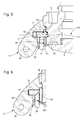
figure 5 est une coupe partielle du même ensemble, selon un plan perpendiculaire au fond de la boîte, et selon la coupe A-A de lafigure 4 ; - la
figure 6 est similaire à lafigure 5 , selon la coupe B-B de lafigure 4 ; - la
figure 7 est similaire à lafigure 5 , selon la coupe C-C de lafigure 4 ; - la
figure 8 est similaire à lafigure 5 , selon la coupe D-D de lafigure 4 ; - la
figure 9 est une vue analogue à lafigure 4 du même ensemble, dans une position d'arrêt déverrouillé, avec indication des zones de coupe des figures suivantes ; - la
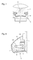
figure 10 est une coupe partielle du même ensemble, selon un plan perpendiculaire au fond de la boîte, et selon la coupe E-E de lafigure 9 ; - la
figure 11 est similaire à lafigure 10 , selon la coupe F-F de lafigure 9 ; - la
figure 12 est similaire à lafigure 10 , selon la coupe G-G de lafigure 9 ; - la
figure 13 est similaire à lafigure 10 , selon la coupe H-H de lafigure 9 ; - la
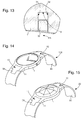
figure 14 représente, de façon schématisée, et en perspective, une montre selon l'invention, comportant un bracelet selon l'invention équipé de deux maillons d'extrémité selon l'invention ; - la
figure 14 représente, de façon schématisée, et en perspective, un bijou selon l'invention, comportant un bracelet selon l'invention équipé de deux maillons d'extrémité selon l'invention. - L'invention se propose d'offrir à l'utilisateur la possibilité d'effectuer facilement, et de façon sécurisée, le changement du bracelet équipant sa montre, et ceci avec le moins possible d'altération de la boîte de montre d'une collection considérée, afin de conserver l'esthétique de la face avant et du chant de la montre, et aussi de proposer une montre à bracelet interchangeable pour un coût différentiel de production le plus bas possible.
- Le changement de bracelet doit pouvoir s'effectuer sans outil, et sans manipulation délicate, tout en permettant une transformation aussi radicale que rapide entre un bracelet cuir et un bracelet métallique articulé, par exemple, ou encore une adaptation du bracelet aux vêtements et/ou bijoux portés par l'utilisateur, ou à la carnation de l'utilisateur, selon les circonstances d'emploi de la montre. Le bracelet interchangeable permet, encore, d'échanger instantanément des bracelets de longueur différente, ce qui permet aux détaillants et revendeurs d'offrir immédiatement à leur clientèle des montres parfaitement adaptées.
- Aussi l'invention consiste à mettre en oeuvre une liaison d'interface entre, d'une part la boîte de montre, notamment mais non limitativement la carrure, et d'autre part des extrémités de bracelet. L'invention est ici plus précisément décrite au cas préféré de maillons d'extrémité de bracelet, réalisables en série à un coût maîtrisable, qu'il suffit d'intégrer à un corps de bracelet, mais il est également possible de choisir une réalisation d'un bracelet d'un seul tenant sans embout rapporté, et incluant les fonctionnalités d'interchangeabilité et de verrouillage nécessaires au bon fonctionnement, mais naturellement à un coût de revient plus élevé. L'homme du métier saura transposer sans le moindre problème l'agencement, décrit ci-après pour un maillon d'extrémité, à un bracelet entier.
- L'invention concerne ainsi préférentiellement un maillon 10 d'extrémité de bracelet de montre, pour un bracelet 90, pour l'équipement amovible d'une boîte 1 d'une montre 100.
- Cette boîte 1 comporte, pour la réception d'un tel maillon 10, au moins une encoche secondaire 3 dite transversale, chacune agencée pour l'introduction d'un tenon 30, ou d'un tourillon, ou similaire, que comporte le maillon 10. Cette encoche secondaire 3 est de préférence borgne, de façon à limiter la course du tenon 30 dans cette rainure, dans une position de butée.
- Dans un cas particulier, non limitatif et tel qu'illustré par les figures, cette encoche secondaire 3 est droite: c'est en particulier le cas lorsque le maillon 10 porte un ou plusieurs tenons 30 parallélépipédiques, tel que visible sur les
figures 2, 3 , et13 . L'encoche secondaire 3 peut, dans une autre variante non illustrée, être courbe si le tenon 30 ou équivalent est de forme cylindrique ou similaire. - Dans ce cas particulier d'encoche secondaire 3 droite, elle est plus particulièrement délimité par deux surfaces d'appui secondaires 31, 32, qui sont parallèles à un plan secondaire PS définissant une direction d'insertion du maillon 10.
- Chaque encoche secondaire 3 est de préférence portée par une zone renforcée de la boîte 1, notamment une corne 11. En effet, c'est le couple formé par l'encoche secondaire 3 et le tenon 30 correspondant qui doit être assez largement dimensionné pour encaisser les efforts, notamment de traction, de torsion, et les accélérations, subis par le bracelet et la boîte 1. L'insertion facile du maillon 10 dans cette encoche secondaire 3, ou de préférence dans ces encoches secondaires 3, préférablement symétriques par rapport à un plan de symétrie, assure l'interchangeabilité des bracelets 90 par rapport à la boîte 1. De la même façon, l'extraction doit être conçue pour ne rencontrer aucun obstacle.
- Pour assurer la fonction de sécurité, et l'implantation d'un mécanisme de verrouillage du maillon 10 quand son tenon 30 ou ses tenons 30 est ou sont en position de butée en fond d'encoche secondaire 3, le mécanisme comporte un système de verrouillage-déverrouillage.
- A cet effet, la boîte 1, ou bien comporte un usinage particulier tel que visible pour la variante particulière et non limitative illustrée par les figures, ou bien porte un élément rapporté comportant un tel usinage particulier.
- De façon préférée, cet usinage particulier comporte au moins une encoche principale 2 longitudinale, qui est délimitée par deux surfaces d'appui principales 21, 22 parallèles à un plan principal PP. Plus particulièrement, quand chaque encoche secondaire 3 est droite selon un plan secondaire PS, le plan principal PP est sécant ou orthogonal avec ce plan secondaire PS.
- Une telle encoche principale 2 comportant deux faces parallèles est très facile à réaliser, par tournage ou par fraisage. Elle est de préférence située entre les cornes 11 de la boîte 1, tel que visible sur les figures, et est presque invisible lorsque le maillon 10 ou le bracelet 90 est en place. Pour la mise en l'oeuvre de l'invention, il suffit donc que la boîte 1 comporte l'encoche principale 2, et la ou les encoches secondaires 3. Aucun autre composant n'est nécessaire au niveau de la boîte 1, qui peut ainsi conserver toute sa pureté de formes, et ses emplois usuels.
- Le maillon 10 comporte un embout 56, qui en constitue la partie la plus massive, et qui comporte lui-même, pour son insertion et sa fixation à la boîte 1, au moins un tel tenon complémentaire 30 agencé pour coopérer de façon complémentaire et à jeu minimal avec une encoche secondaire 3.
- Pour assurer la fonction de verrouillage, le maillon 10 comporte au moins un verrou 50.
- Selon l'invention, ce verrou 50 comporte un tiroir d'arrêt 51, qui est agencé pour coopérer de façon complémentaire et à jeu minimal avec l'encoche principale 2, dans une position de verrouillage vers laquelle le tiroir d'arrêt 51 est ramené par des moyens de rappel élastique 52 que comporte le verrou 50. Ce verrou 50 comporte encore des moyens intrinsèques de déverrouillage, qui sont agencés pour être directement manoeuvrés par un doigt d'un utilisateur, pour éloigner le tiroir d'arrêt 51 de l'encoche principale 2 de la boîte 1. Ainsi aucun outil n'est nécessaire, ni pour effectuer le déverrouillage ou le verrouillage, ni pour effectuer l'insertion ou l'extraction du maillon 10 par rapport à la boîte 1.
- A ce propos, si l'invention est décrite sous sa forme préférée où le maillon 10 comporte une partie mâle coopérant avec une partie femelle de la boîte 1, la configuration inverse est possible, sans s'éloigner de l'invention.
- Plus particulièrement, tel qu'illustré, le tiroir d'arrêt 51 comporte deux surfaces planes parallèles, qui sont agencées pour coopérer en appui avec les surfaces d'appui principales 21, 22, d'une encoche 2 d'une boîte 1, dans laquelle encoche 2 le tiroir d'arrêt 51 circule de préférence à jeu minimal.
- Plus particulièrement, et tel qu'illustré par les figures, l'embout 56 est symétrique par rapport à un plan de symétrie orthogonal à un plan selon lequel s'étend le tiroir d'arrêt 51.
- Plus particulièrement, le verrou 50 comporte un capot 53 pour un guidage antérieur du tiroir d'arrêt 51, à proximité d'une encoche principale 2 formant gâche, que comporte une boîte 1 recevant le maillon 10. Sur les figures, le tiroir d'arrêt 51 est guidé dans un premier guidage 530 que comporte le capot 53. Ce capot 53 protège l'embout 56 ; très peu visible de l'extérieur, il peut être réalisé dans un matériau moins noble et plus résistant à l'usure, comme un acier ou similaire, que le matériau constituant l'embout 56, qui est une pièce d'aspect, de design harmonisé avec celui de la boîte 1, et souvent dans le même matériau et la même finition, cet embout 56 pouvant par exemple être en alliage d'or ou similaire.
- Et l'embout 56, ou bien le verrou 50, comporte une chambre 11 de guidage postérieur du tiroir d'arrêt 51, cette chambre 11 assurant encore de préférence la réception des moyens de rappel élastique 52, illustrés de façon non limitative par une lame ressort.
- Plus particulièrement, le capot 53 est fixé sur l'embout 56 par au moins une vis 58.
- Pour sa manoeuvre, le verrou 50 comporte de préférence un bouton poussoir 54, qui est agencé pour être manoeuvré par un doigt d'un utilisateur, pour commander un déverrouillage du verrou 50 par recul du tiroir d'arrêt 51 sous une poussée imprimée à ce bouton poussoir 54.
- Dans une exécution avantageuse, le bouton poussoir 54 comporte au moins une came ou un biseau oblique 542, qui est agencé pour coopérer avec une came complémentaire ou un biseau oblique complémentaire 512, que comporte le tiroir d'arrêt 51, tel que visible sur les
figures 6 et11 . - Plus particulièrement, la course du bouton poussoir 54 est orthogonale à celle du tiroir d'arrêt 51.
- De préférence, le bouton poussoir 54 est guidé dans un deuxième guidage 55, notamment une lumière 531, que comporte le capot 53, et/ou ce bouton poussoir 54 est guidé dans un troisième guidage 57 que comporte l'embout 56.
- L'invention concerne aussi une montre 100, comportant une boîte 1 de montre ou de bijou laquelle comporte, pour la réception d'au moins un tel maillon 10, au moins une encoche secondaire 3 transversale, cette boîte 1 comportant au moins une encoche principale 2 longitudinale délimitée par deux surfaces d'appui principales 21, 22, parallèles à un plan principal PP. Et cette montre 100 comporte au moins un tel maillon d'extrémité 10 de bracelet, agencé pour la coopération d'insertion et de verrouillage avec sa boîte 1.
- Plus particulièrement, la boîte 1 comporte, pour la réception d'au moins un maillon 10, au moins une encoche secondaire 3 transversale, que délimitent deux surfaces d'appui secondaires 31, 32, parallèles à un plan secondaire PS définissant une direction d'insertion du maillon 10, ce plan secondaire PS étant sécant ou orthogonal par rapport au plan principal PP.
- Plus particulièrement, dans une réalisation préférée et en projection sur le plan principal PP, les surfaces d'appui secondaires 31, 32 sont distantes des surfaces d'appui principales 21, 22.
- Plus particulièrement, dans une réalisation préférée et en projection sur le plan principal PP, les surfaces d'appui secondaires 31,32 ne sont pas alignées avec les surfaces d'appui principales 21, 22.
- Dans une réalisation particulière, non limitative, illustrée par les figures, le plan principal PP est orthogonal au plan secondaire PS.
- Plus particulièrement, la boîte 1 comporte un fond 6 parallèle au plan principal PP.
- Dans une réalisation particulière et tel que visible sur les figures, la boîte 1 comporte une surface d'épaulement 9 parallèle au plan principal PP, et un maillon 10, et de préférence chaque maillon 10 agencé pour coopérer avec cette boîte 1, comporte un embout 56 qui comporte une surface d'ablocage 59 agencée pour coopérer en appui de blocage avec cette surface d'épaulement 9.
- Plus particulièrement, la montre 100 comporte au moins un bracelet amovible 90, comportant à chacune de ses deux extrémités un tel maillon 10 d'extrémité amovible, les maillons 10 étant agencés de part et d'autre de la boîte 1 de montre ou de bijou.
- Plus particulièrement, la montre 100 comporte une pluralité de tels bracelets amovibles 90 interchangeables entre eux.
- L'invention concerne encore un bijou 200 comportant une boîte 1 de bijou laquelle comporte, pour la réception d'au moins un tel maillon 10, au moins une encoche secondaire 3 transversale, cette boîte 1 comportant au moins une encoche principale 2 longitudinale délimitée par deux surfaces d'appui principales 21, 22, parallèles à un plan principal PP, où ce bijou 200 comporte au moins un tel maillon d'extrémité 10 de bracelet, agencé pour la coopération d'insertion et de verrouillage avec la boîte 1. Toutes les caractéristiques décrites ci-dessus pour une boîte de montre, et pour un bracelet de montre, sont bien sûr applicables à un tel bijou 200 et à un bracelet de bijou.
Claims (22)
- Maillon (10) d'extrémité de bracelet de montre ou de bijou, pour l'équipement amovible d'une boîte (1) de montre ou de bijou laquelle comporte, pour la réception d'un dit maillon (10), au moins une encoche secondaire (3) transversale, ladite boîte (1) comportant au moins une encoche principale (2) longitudinale délimitée par deux surfaces d'appui principales (21, 22) parallèles à un plan principal (PP), ledit maillon (10) comportant un embout (56) qui comporte lui-même, pour sa fixation à ladite boîte (1), au moins un tenon complémentaire (30) agencé pour coopérer de façon complémentaire et à jeu minimal avec une dite encoche secondaire (3), et ledit maillon (10) comportant au moins un verrou (50), caractérisé en ce que ledit verrou (50) comporte un tiroir d'arrêt (51) agencé pour coopérer de façon complémentaire et à jeu minimal avec ladite encoche principale (2) dans une position de verrouillage vers laquelle ledit tiroir d'arrêt (51) est ramené par des moyens de rappel élastique (52) que comporte ledit verrou (50), lequel comporte des moyens intrinsèques de déverrouillage agencés pour être directement manoeuvrés par un doigt d'un utilisateur, pour éloigner ledit tiroir d'arrêt (51) de ladite encoche principale (2) de ladite boîte (1).
- Maillon d'extrémité (10) selon la revendication 1, caractérisé en ce que ledit tiroir d'arrêt (51) comporte deux surfaces planes parallèles agencées pour coopérer en appui avec lesdits surfaces d'appui principales (21, 22) d'une dite encoche (2) d'une dite boîte (1).
- Maillon d'extrémité (10) selon la revendication 1 ou 2, caractérisé en ce que ledit embout (56) est symétrique par rapport à un plan de symétrie orthogonal à un plan selon lequel s'étend ledit tiroir d'arrêt (51).
- Maillon d'extrémité (10) selon l'une des revendications 1 à 3, caractérisé en ce que ledit verrou (50) comporte un capot (53) pour un guidage antérieur dudit tiroir d'arrêt (51) à proximité d'une dite encoche principale (2) formant gâche, que comporte une dite boîte (1) recevant ledit maillon (10), et en ce que ledit embout (56) ou ledit verrou (50) comporte une chambre (11) de guidage postérieur dudit tiroir d'arrêt (51) et de réception desdits moyens de rappel élastique (52).
- Maillon d'extrémité (10) selon la revendication 4, caractérisé en ce que ledit capot (53) est fixé sur ledit embout (56) par au moins une vis (58).
- Maillon d'extrémité (10) selon la revendication 4 ou 5, caractérisé en ce que ledit tiroir d'arrêt (51) est guidé dans un premier guidage (530) que comporte ledit capot (53).
- Maillon d'extrémité (10) selon l'une des revendications 1 à 6, caractérisé en ce que ledit verrou (50) comporte un bouton poussoir (54) agencé pour être manoeuvré par un doigt d'un utilisateur, pour commander un déverrouillage dudit verrou (50) par recul dudit tiroir d'arrêt (51) sous une poussée imprimée audit bouton poussoir (54).
- Maillon d'extrémité (10) selon la revendication 7, caractérisé en ce que ledit bouton poussoir (54) comporte au moins une came ou un biseau oblique (542) agencé pour coopérer avec une came complémentaire ou un biseau oblique complémentaire (512) que comporte ledit tiroir d'arrêt (51).
- Maillon d'extrémité (10) selon la revendication 7 ou 8, caractérisé en ce que la course dudit bouton poussoir (54) est orthogonale à celle dudit tiroir d'arrêt (51).
- Maillon d'extrémité (10) selon la revendication 4 et l'une des revendications 7 à 9, caractérisé en ce que ledit bouton poussoir (54) est guidé dans un deuxième guidage (55, 531) que comporte ledit capot (53).
- Maillon d'extrémité (10) selon l'une des revendications 7 à 10, caractérisé en ce que ledit bouton poussoir (54) est guidé dans un troisième guidage (57) que comporte ledit embout (56).
- Bracelet (90) comportant au moins un maillon (10) d'extrémité selon une des revendications 1 à 11.
- Montre (100) comportant une boîte (1) de montre laquelle comporte, pour la réception d'au moins un dit maillon (10), au moins une encoche secondaire (3) transversale, ladite boîte (1) comportant au moins une encoche principale (2) longitudinale délimitée par deux surfaces d'appui principales (21, 22) parallèles à un plan principal (PP), caractérisée en ce que ladite montre (100) comporte au moins un maillon d'extrémité (10) de bracelet selon une des revendications 1 à 12, agencé pour la coopération d'insertion et de verrouillage avec ladite boîte (1).
- Montre (100) selon la revendication 13, caractérisée en ce que ladite boîte (1) comporte, pour la réception d'au moins un dit maillon (10), au moins une encoche secondaire (3) transversale, que délimitent deux surfaces d'appui secondaires (31, 32) parallèles à un plan secondaire (PS) définissant une direction d'insertion dudit maillon (10), ledit plan secondaire (PS) étant sécant ou orthogonal par rapport audit plan principal (PP).
- Montre (100) selon la revendication 14, caractérisée en ce que, en projection sur ledit plan principal (PP), lesdites surfaces d'appui secondaires (31, 32) sont distantes desdites surfaces d'appui principales (21, 22).
- Montre (100) selon la revendication 14, caractérisée en ce que, en projection sur ledit plan principal (PP), lesdites surfaces d'appui secondaires (31, 32) ne sont pas alignées avec lesdites surfaces d'appui principales (21, 22).
- Montre (100) selon l'une des revendications 14 à 16, caractérisée en ce que ledit plan principal (PP) est orthogonal audit plan secondaire (PS).
- Montre (100) selon l'une des revendications 13 à 17, caractérisée en ce que ladite boîte (1) comporte un fond (6) parallèle audit plan principal (PP).
- Montre (100) selon l'une des revendications 13 à 18, caractérisée en ce que ladite boîte (1) comporte une surface d'épaulement (9) parallèle audit plan principal (PP), et en ce qu'un dit maillon (10) comporte un dit embout (56) qui comporte une surface d'ablocage (59) agencée pour coopérer en appui de blocage avec ladite surface d'épaulement (9).
- Montre (100) selon l'une des revendications 13 à 19, comportant au moins un bracelet amovible (90) comportant à chacune de ses deux extrémités un dit maillon (10) d'extrémité amovible, lesdits maillons (10) étant agencés de part et d'autre de ladite boîte (1) de montre.
- Montre (100) selon la revendication 20, caractérisée en ce qu'elle comporte une pluralité de dits bracelets amovibles (90) interchangeables entre eux.
- Bijou (200) comportant une boîte (1) de bijou laquelle comporte, pour la réception d'au moins un dit maillon (10), au moins une encoche secondaire (3) transversale, ladite boîte (1) comportant au moins une encoche principale (2) longitudinale délimitée par deux surfaces d'appui principales (21, 22) parallèles à un plan principal (PP), caractérisée en ce que ledit bijou (200) comporte au moins un maillon d'extrémité (10) de bracelet selon une des revendications 1 à 12, agencé pour la coopération d'insertion et de verrouillage avec ladite boîte (1).
Priority Applications (6)
| Application Number | Priority Date | Filing Date | Title |
|---|---|---|---|
| EP16178320.4A EP3266333B1 (fr) | 2016-07-07 | 2016-07-07 | Montre et bijou a bracelet interchangeable |
| US15/616,159 US10365614B2 (en) | 2016-07-07 | 2017-06-07 | Watch and item of jewellery with interchangeable wristband |
| JP2017115682A JP6530784B2 (ja) | 2016-07-07 | 2017-06-13 | 交換可能なリストバンドを備えた腕時計及び装飾品 |
| KR1020170081676A KR101890069B1 (ko) | 2016-07-07 | 2017-06-28 | 상호교환가능한 손목밴드를 가진 시계 및 보석류 |
| CN201710546457.6A CN107581725B (zh) | 2016-07-07 | 2017-07-06 | 具有可互换式腕带的手表和珠宝物品 |
| HK18108415.0A HK1248482B (zh) | 2016-07-07 | 2018-06-29 | 具有可互换式腕带的手表和珠宝物品 |
Applications Claiming Priority (1)
| Application Number | Priority Date | Filing Date | Title |
|---|---|---|---|
| EP16178320.4A EP3266333B1 (fr) | 2016-07-07 | 2016-07-07 | Montre et bijou a bracelet interchangeable |
Publications (2)
| Publication Number | Publication Date |
|---|---|
| EP3266333A1 true EP3266333A1 (fr) | 2018-01-10 |
| EP3266333B1 EP3266333B1 (fr) | 2019-05-22 |
Family
ID=56411411
Family Applications (1)
| Application Number | Title | Priority Date | Filing Date |
|---|---|---|---|
| EP16178320.4A Active EP3266333B1 (fr) | 2016-07-07 | 2016-07-07 | Montre et bijou a bracelet interchangeable |
Country Status (6)
| Country | Link |
|---|---|
| US (1) | US10365614B2 (fr) |
| EP (1) | EP3266333B1 (fr) |
| JP (1) | JP6530784B2 (fr) |
| KR (1) | KR101890069B1 (fr) |
| CN (1) | CN107581725B (fr) |
| HK (1) | HK1248482B (fr) |
Cited By (4)
| Publication number | Priority date | Publication date | Assignee | Title |
|---|---|---|---|---|
| KR20200083227A (ko) * | 2018-12-27 | 2020-07-08 | 오메가쏘시에떼아노님 | 환형의 링이 제공된 시계 케이스, 및 손목시계 및 상기 손목시계를 포함하는 손목시계 조립체 키트 |
| CN112137256A (zh) * | 2019-06-28 | 2020-12-29 | 蒙特雷布勒盖股份有限公司 | 附装链的装置 |
| EP4023098A1 (fr) | 2020-12-30 | 2022-07-06 | Glashütter Uhrenbetrieb GmbH | Système à libération rapide pour montre bracelet |
| EP4527237A1 (fr) | 2023-09-21 | 2025-03-26 | Glashütter Uhrenbetrieb GmbH | Système de libération rapide pour bracelet de montre |
Families Citing this family (26)
| Publication number | Priority date | Publication date | Assignee | Title |
|---|---|---|---|---|
| US10182623B2 (en) | 2014-08-11 | 2019-01-22 | Apple Inc. | Consumer product attachment systems having locking or expansion characteristics |
| US10184506B2 (en) * | 2014-08-11 | 2019-01-22 | Apple Inc. | Captive elements of an attachment system |
| US10085523B2 (en) | 2014-08-11 | 2018-10-02 | Apple Inc. | Attachment system for an electronic device |
| EP3266333B1 (fr) * | 2016-07-07 | 2019-05-22 | The Swatch Group Research and Development Ltd. | Montre et bijou a bracelet interchangeable |
| KR102500141B1 (ko) * | 2016-08-30 | 2023-02-15 | 삼성전자주식회사 | 개선된 체결 구조를 갖는 스트랩 및 그것을 포함하는 웨어러블 전자 장치 |
| USD834980S1 (en) * | 2016-12-09 | 2018-12-04 | Richemont International Sa | Watch dial |
| SG11201908297WA (en) * | 2017-03-07 | 2019-10-30 | Titan Company Ltd | A dial for a ceramic timepiece and a method for manufacturing |
| US10327520B1 (en) * | 2017-08-17 | 2019-06-25 | Apple Inc. | Attachment system for watchband |
| US10809666B2 (en) | 2018-05-22 | 2020-10-20 | Fitbit, Inc. | Low-profile band latch mechanism |
| CH715154B1 (fr) * | 2018-07-05 | 2022-09-15 | Cornu Et Cie S A | Organe de fixation d'un bracelet et montre-bracelet. |
| US11839583B1 (en) | 2018-09-11 | 2023-12-12 | Encora, Inc. | Apparatus and method for reduction of neurological movement disorder symptoms using wearable device |
| US12318341B2 (en) | 2018-09-11 | 2025-06-03 | Encora, Inc. | Apparatus and method for reduction of neurological movement disorder symptoms using wearable device |
| KR102210469B1 (ko) * | 2019-03-15 | 2021-02-02 | (주)펫펄스랩 | 밴드형 애완동물 착용장치 |
| EP3798742B1 (fr) | 2019-09-24 | 2025-05-28 | ETA SA Manufacture Horlogère Suisse | Dispositif de connexion carrure-corne pour une montre |
| US11033082B1 (en) * | 2020-04-14 | 2021-06-15 | Fitbit, Inc. | Wearable device straps and attachment hardware therefor |
| EP3958069B1 (fr) * | 2020-08-18 | 2024-06-12 | The Swatch Group Research and Development Ltd | Boîte de montre munie d'un élément d'habillage |
| EP3982207A1 (fr) * | 2020-10-06 | 2022-04-13 | ETA SA Manufacture Horlogère Suisse | Montre a cornes amovibles |
| CN112716119B (zh) * | 2020-12-29 | 2022-08-26 | 维沃移动通信有限公司 | 手表 |
| WO2022227898A1 (fr) * | 2021-04-29 | 2022-11-03 | Oppo广东移动通信有限公司 | Structure détachable, dispositif pouvant être porté, bracelet de montre et tête de montre |
| CN113273773B (zh) * | 2021-05-18 | 2024-03-01 | 北京小米移动软件有限公司 | 一种连接组件和穿戴式设备 |
| USD957266S1 (en) * | 2021-07-16 | 2022-07-12 | Liuyang Zhou | Watch case |
| KR20230027506A (ko) * | 2021-08-19 | 2023-02-28 | 삼성전자주식회사 | 착탈 가능한 착용 부재 및 그를 포함하는 웨어러블 전자 장치 |
| US20230210230A1 (en) * | 2021-12-30 | 2023-07-06 | Peer Inc | Watchband connection mechanism system and method |
| EP4615225A1 (fr) * | 2022-12-16 | 2025-09-17 | Hill's Pet Nutrition, Inc. | Appareil d'informations sur un animal pouvant être porté |
| WO2024158161A1 (fr) * | 2023-01-25 | 2024-08-02 | 삼성전자 주식회사 | Dispositif électronique comprenant des éléments de fixation couplés à des supports |
| JP7718475B2 (ja) * | 2023-12-21 | 2025-08-05 | セイコーエプソン株式会社 | バンド保持機構、リスト機器、リスト機器本体部、バンド保持装置、および、バンド |
Citations (3)
| Publication number | Priority date | Publication date | Assignee | Title |
|---|---|---|---|---|
| EP1128237A1 (fr) * | 2000-02-25 | 2001-08-29 | Conseils et Manufactures VLG SA | Dispositif de fixation d'un bracelet sur une boíte de montre |
| US20050207284A1 (en) * | 2004-03-22 | 2005-09-22 | Haruki Hiranuma | Wristwatch |
| EP1820415A1 (fr) * | 2006-02-20 | 2007-08-22 | Hirsch Armbänder Gesellschaft m.b.H. | Dispositif destiné à la connexion entre une partie terminale d'une bande et une autre partie |
Family Cites Families (27)
| Publication number | Priority date | Publication date | Assignee | Title |
|---|---|---|---|---|
| US3589341A (en) * | 1969-09-24 | 1971-06-29 | Jacob Krebs | Animal collar with magnetic fastener |
| GB1426346A (en) * | 1972-11-13 | 1976-02-25 | Suisse Pour Lindustrie Horloge | Clasp fastener for fastening togehter two elements |
| US4266326A (en) * | 1979-08-06 | 1981-05-12 | Hong Lai F | Watchband connector |
| US4432655A (en) * | 1982-10-13 | 1984-02-21 | Bulova Watch Company, Inc. | Integrated watch case and bracelet assembly |
| JPS59174019U (ja) * | 1983-05-10 | 1984-11-20 | オリエント時計株式会社 | 腕時計ケ−スのバネ棒取付け装置 |
| WO1986004696A1 (fr) * | 1985-02-05 | 1986-08-14 | Victor Alexander Milles | Procede de fabrication de pieces de bijouterie ou de montres-bracelets |
| JPS6235510U (fr) * | 1985-08-22 | 1987-03-02 | ||
| US4664533A (en) * | 1986-10-06 | 1987-05-12 | Bulova Watch Co., Inc. | Watch case and bracelet assembly |
| JPH0174813U (fr) * | 1987-11-10 | 1989-05-22 | ||
| KR100703475B1 (ko) * | 2004-04-09 | 2007-04-03 | 삼성전자주식회사 | 휴대 단말기의 배터리팩 락킹 장치 |
| EP1652443A1 (fr) * | 2004-10-28 | 2006-05-03 | Meier BT | Fermoir de bracelet à boucle glissante |
| EP1693719B1 (fr) * | 2005-02-18 | 2008-04-23 | Raymond Wiel S.A. | Dispositif de fixation d'un bracelet interchangeable sur une montre |
| AT9011U1 (de) * | 2005-09-26 | 2007-04-15 | Hirsch Armbaender | Vorrichtung zum anschluss eines bandes an einen weiteren teil |
| US8240011B2 (en) * | 2010-02-17 | 2012-08-14 | Paul Hartzband | Device for fastening interchangeable watchstraps with sliding lock mechanism |
| US8007165B1 (en) * | 2010-02-19 | 2011-08-30 | Invicta Watch Company Of America, Inc. | Coupling assembly for a wristwatch |
| CN102166058A (zh) * | 2010-02-26 | 2011-08-31 | 保罗·哈茨班德 | 用于将可互换表带与滑锁机构紧固的装置 |
| EP2767184B1 (fr) * | 2013-02-13 | 2015-04-08 | Omega SA | Fermoir pour bracelet de montre |
| JP5790714B2 (ja) * | 2013-06-20 | 2015-10-07 | トヨタ自動車株式会社 | 車両下部構造 |
| US10182623B2 (en) * | 2014-08-11 | 2019-01-22 | Apple Inc. | Consumer product attachment systems having locking or expansion characteristics |
| US10184506B2 (en) * | 2014-08-11 | 2019-01-22 | Apple Inc. | Captive elements of an attachment system |
| US10085523B2 (en) * | 2014-08-11 | 2018-10-02 | Apple Inc. | Attachment system for an electronic device |
| US9949537B2 (en) * | 2015-03-06 | 2018-04-24 | Apple Inc. | Clasp mechanism for wrist-worn devices |
| CN204838303U (zh) * | 2015-08-12 | 2015-12-09 | 深圳市埃微信息技术有限公司 | 智能手环壳体与表带按键型分离结构 |
| WO2017026728A1 (fr) * | 2015-08-13 | 2017-02-16 | Samsung Electronics Co., Ltd. | Élément d'accouplement et dispositif électronique le comprenant |
| CN105310198B (zh) * | 2015-11-10 | 2017-05-31 | 深圳市倍轻松科技股份有限公司 | 一种手表 |
| US10258115B2 (en) * | 2015-12-29 | 2019-04-16 | Smart Strappers LLC | Watch straps |
| EP3266333B1 (fr) * | 2016-07-07 | 2019-05-22 | The Swatch Group Research and Development Ltd. | Montre et bijou a bracelet interchangeable |
-
2016
- 2016-07-07 EP EP16178320.4A patent/EP3266333B1/fr active Active
-
2017
- 2017-06-07 US US15/616,159 patent/US10365614B2/en active Active
- 2017-06-13 JP JP2017115682A patent/JP6530784B2/ja active Active
- 2017-06-28 KR KR1020170081676A patent/KR101890069B1/ko active Active
- 2017-07-06 CN CN201710546457.6A patent/CN107581725B/zh active Active
-
2018
- 2018-06-29 HK HK18108415.0A patent/HK1248482B/zh unknown
Patent Citations (3)
| Publication number | Priority date | Publication date | Assignee | Title |
|---|---|---|---|---|
| EP1128237A1 (fr) * | 2000-02-25 | 2001-08-29 | Conseils et Manufactures VLG SA | Dispositif de fixation d'un bracelet sur une boíte de montre |
| US20050207284A1 (en) * | 2004-03-22 | 2005-09-22 | Haruki Hiranuma | Wristwatch |
| EP1820415A1 (fr) * | 2006-02-20 | 2007-08-22 | Hirsch Armbänder Gesellschaft m.b.H. | Dispositif destiné à la connexion entre une partie terminale d'une bande et une autre partie |
Cited By (5)
| Publication number | Priority date | Publication date | Assignee | Title |
|---|---|---|---|---|
| KR20200083227A (ko) * | 2018-12-27 | 2020-07-08 | 오메가쏘시에떼아노님 | 환형의 링이 제공된 시계 케이스, 및 손목시계 및 상기 손목시계를 포함하는 손목시계 조립체 키트 |
| CN112137256A (zh) * | 2019-06-28 | 2020-12-29 | 蒙特雷布勒盖股份有限公司 | 附装链的装置 |
| EP4023098A1 (fr) | 2020-12-30 | 2022-07-06 | Glashütter Uhrenbetrieb GmbH | Système à libération rapide pour montre bracelet |
| US12127642B2 (en) | 2020-12-30 | 2024-10-29 | Glashütter Uhrenbetrieb GmbH | Quick-release system for a watch bracelet |
| EP4527237A1 (fr) | 2023-09-21 | 2025-03-26 | Glashütter Uhrenbetrieb GmbH | Système de libération rapide pour bracelet de montre |
Also Published As
| Publication number | Publication date |
|---|---|
| CN107581725B (zh) | 2019-05-28 |
| US20180011448A1 (en) | 2018-01-11 |
| HK1248482B (zh) | 2020-07-03 |
| KR101890069B1 (ko) | 2018-09-20 |
| EP3266333B1 (fr) | 2019-05-22 |
| JP2018000950A (ja) | 2018-01-11 |
| JP6530784B2 (ja) | 2019-06-12 |
| CN107581725A (zh) | 2018-01-16 |
| KR20180006302A (ko) | 2018-01-17 |
| US10365614B2 (en) | 2019-07-30 |
Similar Documents
| Publication | Publication Date | Title |
|---|---|---|
| EP3266333B1 (fr) | Montre et bijou a bracelet interchangeable | |
| EP3756501B1 (fr) | Dispositif de fixation d'un bracelet | |
| HK1248482A1 (en) | Watch and item of jewellery with interchangeable wristband | |
| EP3769640A1 (fr) | Fermoir pour bracelet de montre | |
| EP3618662B1 (fr) | Fermoir pour article de bijouterie et joaillerie | |
| EP4129113A1 (fr) | Boucle securisee | |
| CH712656A2 (fr) | Montre et bijou à bracelet interchangeable. | |
| WO2021116560A1 (fr) | Dispositif d'assemblage amovible entre deux pièces | |
| EP2813156B1 (fr) | Fermoir pour bijou ou montre-bracelet | |
| EP1664940B1 (fr) | Dispositif de fixation d'un bracelet | |
| WO2022137096A1 (fr) | Bracelet | |
| EP3753439B1 (fr) | Dispositif de liaison mécanique amovible entre un bracelet et une pièce mécanique | |
| EP1247469B1 (fr) | Fermoir à deux poussoirs guidés en déplacement l'un par rapport à l'autre | |
| EP4233628A1 (fr) | Fermoir pour montre-bracelet | |
| CH712223A2 (fr) | Montre mécanique modulaire. | |
| CH718226A2 (fr) | Système d'attache rapide pour un bracelet de montre. | |
| EP4544951A1 (fr) | Fermoir pour bracelet | |
| EP4390571B1 (fr) | Dispositif de fixation d'un bracelet | |
| CH721143A2 (fr) | Système à libération rapide pour un bracelet de montre | |
| CH721248A1 (fr) | Fermoir pour article de joaillerie | |
| CH721220A2 (fr) | Dispositif permettant de relier un bracelet au boîtier d'une montre | |
| CH715154B1 (fr) | Organe de fixation d'un bracelet et montre-bracelet. | |
| CH720345A2 (fr) | Dispositif de fixation d'un bracelet | |
| CH718228B1 (fr) | Dispositif d'attache d'un bracelet à une pièce d'horlogerie, de bijouterie ou de joaillerie. | |
| EP4140352A1 (fr) | Dispositif de réglage en longueur d'un bracelet de montre |
Legal Events
| Date | Code | Title | Description |
|---|---|---|---|
| PUAI | Public reference made under article 153(3) epc to a published international application that has entered the european phase |
Free format text: ORIGINAL CODE: 0009012 |
|
| STAA | Information on the status of an ep patent application or granted ep patent |
Free format text: STATUS: THE APPLICATION HAS BEEN PUBLISHED |
|
| AK | Designated contracting states |
Kind code of ref document: A1 Designated state(s): AL AT BE BG CH CY CZ DE DK EE ES FI FR GB GR HR HU IE IS IT LI LT LU LV MC MK MT NL NO PL PT RO RS SE SI SK SM TR |
|
| AX | Request for extension of the european patent |
Extension state: BA ME |
|
| STAA | Information on the status of an ep patent application or granted ep patent |
Free format text: STATUS: REQUEST FOR EXAMINATION WAS MADE |
|
| 17P | Request for examination filed |
Effective date: 20180710 |
|
| RBV | Designated contracting states (corrected) |
Designated state(s): AL AT BE BG CH CY CZ DE DK EE ES FI FR GB GR HR HU IE IS IT LI LT LU LV MC MK MT NL NO PL PT RO RS SE SI SK SM TR |
|
| GRAP | Despatch of communication of intention to grant a patent |
Free format text: ORIGINAL CODE: EPIDOSNIGR1 |
|
| STAA | Information on the status of an ep patent application or granted ep patent |
Free format text: STATUS: GRANT OF PATENT IS INTENDED |
|
| INTG | Intention to grant announced |
Effective date: 20190108 |
|
| GRAS | Grant fee paid |
Free format text: ORIGINAL CODE: EPIDOSNIGR3 |
|
| GRAA | (expected) grant |
Free format text: ORIGINAL CODE: 0009210 |
|
| STAA | Information on the status of an ep patent application or granted ep patent |
Free format text: STATUS: THE PATENT HAS BEEN GRANTED |
|
| AK | Designated contracting states |
Kind code of ref document: B1 Designated state(s): AL AT BE BG CH CY CZ DE DK EE ES FI FR GB GR HR HU IE IS IT LI LT LU LV MC MK MT NL NO PL PT RO RS SE SI SK SM TR |
|
| REG | Reference to a national code |
Ref country code: GB Ref legal event code: FG4D Free format text: NOT ENGLISH |
|
| REG | Reference to a national code |
Ref country code: CH Ref legal event code: EP |
|
| REG | Reference to a national code |
Ref country code: IE Ref legal event code: FG4D Free format text: LANGUAGE OF EP DOCUMENT: FRENCH |
|
| REG | Reference to a national code |
Ref country code: DE Ref legal event code: R096 Ref document number: 602016014192 Country of ref document: DE |
|
| REG | Reference to a national code |
Ref country code: AT Ref legal event code: REF Ref document number: 1135013 Country of ref document: AT Kind code of ref document: T Effective date: 20190615 |
|
| REG | Reference to a national code |
Ref country code: NL Ref legal event code: MP Effective date: 20190522 |
|
| REG | Reference to a national code |
Ref country code: LT Ref legal event code: MG4D |
|
| PG25 | Lapsed in a contracting state [announced via postgrant information from national office to epo] |
Ref country code: AL Free format text: LAPSE BECAUSE OF FAILURE TO SUBMIT A TRANSLATION OF THE DESCRIPTION OR TO PAY THE FEE WITHIN THE PRESCRIBED TIME-LIMIT Effective date: 20190522 Ref country code: ES Free format text: LAPSE BECAUSE OF FAILURE TO SUBMIT A TRANSLATION OF THE DESCRIPTION OR TO PAY THE FEE WITHIN THE PRESCRIBED TIME-LIMIT Effective date: 20190522 Ref country code: HR Free format text: LAPSE BECAUSE OF FAILURE TO SUBMIT A TRANSLATION OF THE DESCRIPTION OR TO PAY THE FEE WITHIN THE PRESCRIBED TIME-LIMIT Effective date: 20190522 Ref country code: NO Free format text: LAPSE BECAUSE OF FAILURE TO SUBMIT A TRANSLATION OF THE DESCRIPTION OR TO PAY THE FEE WITHIN THE PRESCRIBED TIME-LIMIT Effective date: 20190822 Ref country code: PT Free format text: LAPSE BECAUSE OF FAILURE TO SUBMIT A TRANSLATION OF THE DESCRIPTION OR TO PAY THE FEE WITHIN THE PRESCRIBED TIME-LIMIT Effective date: 20190922 Ref country code: SE Free format text: LAPSE BECAUSE OF FAILURE TO SUBMIT A TRANSLATION OF THE DESCRIPTION OR TO PAY THE FEE WITHIN THE PRESCRIBED TIME-LIMIT Effective date: 20190522 Ref country code: FI Free format text: LAPSE BECAUSE OF FAILURE TO SUBMIT A TRANSLATION OF THE DESCRIPTION OR TO PAY THE FEE WITHIN THE PRESCRIBED TIME-LIMIT Effective date: 20190522 Ref country code: LT Free format text: LAPSE BECAUSE OF FAILURE TO SUBMIT A TRANSLATION OF THE DESCRIPTION OR TO PAY THE FEE WITHIN THE PRESCRIBED TIME-LIMIT Effective date: 20190522 Ref country code: NL Free format text: LAPSE BECAUSE OF FAILURE TO SUBMIT A TRANSLATION OF THE DESCRIPTION OR TO PAY THE FEE WITHIN THE PRESCRIBED TIME-LIMIT Effective date: 20190522 |
|
| PG25 | Lapsed in a contracting state [announced via postgrant information from national office to epo] |
Ref country code: RS Free format text: LAPSE BECAUSE OF FAILURE TO SUBMIT A TRANSLATION OF THE DESCRIPTION OR TO PAY THE FEE WITHIN THE PRESCRIBED TIME-LIMIT Effective date: 20190522 Ref country code: LV Free format text: LAPSE BECAUSE OF FAILURE TO SUBMIT A TRANSLATION OF THE DESCRIPTION OR TO PAY THE FEE WITHIN THE PRESCRIBED TIME-LIMIT Effective date: 20190522 Ref country code: BG Free format text: LAPSE BECAUSE OF FAILURE TO SUBMIT A TRANSLATION OF THE DESCRIPTION OR TO PAY THE FEE WITHIN THE PRESCRIBED TIME-LIMIT Effective date: 20190822 Ref country code: GR Free format text: LAPSE BECAUSE OF FAILURE TO SUBMIT A TRANSLATION OF THE DESCRIPTION OR TO PAY THE FEE WITHIN THE PRESCRIBED TIME-LIMIT Effective date: 20190823 |
|
| REG | Reference to a national code |
Ref country code: AT Ref legal event code: MK05 Ref document number: 1135013 Country of ref document: AT Kind code of ref document: T Effective date: 20190522 |
|
| PG25 | Lapsed in a contracting state [announced via postgrant information from national office to epo] |
Ref country code: AT Free format text: LAPSE BECAUSE OF FAILURE TO SUBMIT A TRANSLATION OF THE DESCRIPTION OR TO PAY THE FEE WITHIN THE PRESCRIBED TIME-LIMIT Effective date: 20190522 Ref country code: EE Free format text: LAPSE BECAUSE OF FAILURE TO SUBMIT A TRANSLATION OF THE DESCRIPTION OR TO PAY THE FEE WITHIN THE PRESCRIBED TIME-LIMIT Effective date: 20190522 Ref country code: DK Free format text: LAPSE BECAUSE OF FAILURE TO SUBMIT A TRANSLATION OF THE DESCRIPTION OR TO PAY THE FEE WITHIN THE PRESCRIBED TIME-LIMIT Effective date: 20190522 Ref country code: SK Free format text: LAPSE BECAUSE OF FAILURE TO SUBMIT A TRANSLATION OF THE DESCRIPTION OR TO PAY THE FEE WITHIN THE PRESCRIBED TIME-LIMIT Effective date: 20190522 Ref country code: RO Free format text: LAPSE BECAUSE OF FAILURE TO SUBMIT A TRANSLATION OF THE DESCRIPTION OR TO PAY THE FEE WITHIN THE PRESCRIBED TIME-LIMIT Effective date: 20190522 Ref country code: CZ Free format text: LAPSE BECAUSE OF FAILURE TO SUBMIT A TRANSLATION OF THE DESCRIPTION OR TO PAY THE FEE WITHIN THE PRESCRIBED TIME-LIMIT Effective date: 20190522 |
|
| REG | Reference to a national code |
Ref country code: DE Ref legal event code: R097 Ref document number: 602016014192 Country of ref document: DE |
|
| PG25 | Lapsed in a contracting state [announced via postgrant information from national office to epo] |
Ref country code: MC Free format text: LAPSE BECAUSE OF FAILURE TO SUBMIT A TRANSLATION OF THE DESCRIPTION OR TO PAY THE FEE WITHIN THE PRESCRIBED TIME-LIMIT Effective date: 20190522 Ref country code: SM Free format text: LAPSE BECAUSE OF FAILURE TO SUBMIT A TRANSLATION OF THE DESCRIPTION OR TO PAY THE FEE WITHIN THE PRESCRIBED TIME-LIMIT Effective date: 20190522 |
|
| PLBE | No opposition filed within time limit |
Free format text: ORIGINAL CODE: 0009261 |
|
| STAA | Information on the status of an ep patent application or granted ep patent |
Free format text: STATUS: NO OPPOSITION FILED WITHIN TIME LIMIT |
|
| PG25 | Lapsed in a contracting state [announced via postgrant information from national office to epo] |
Ref country code: TR Free format text: LAPSE BECAUSE OF FAILURE TO SUBMIT A TRANSLATION OF THE DESCRIPTION OR TO PAY THE FEE WITHIN THE PRESCRIBED TIME-LIMIT Effective date: 20190522 |
|
| REG | Reference to a national code |
Ref country code: BE Ref legal event code: MM Effective date: 20190731 |
|
| 26N | No opposition filed |
Effective date: 20200225 |
|
| PG25 | Lapsed in a contracting state [announced via postgrant information from national office to epo] |
Ref country code: PL Free format text: LAPSE BECAUSE OF FAILURE TO SUBMIT A TRANSLATION OF THE DESCRIPTION OR TO PAY THE FEE WITHIN THE PRESCRIBED TIME-LIMIT Effective date: 20190522 |
|
| PG25 | Lapsed in a contracting state [announced via postgrant information from national office to epo] |
Ref country code: LU Free format text: LAPSE BECAUSE OF NON-PAYMENT OF DUE FEES Effective date: 20190707 Ref country code: SI Free format text: LAPSE BECAUSE OF FAILURE TO SUBMIT A TRANSLATION OF THE DESCRIPTION OR TO PAY THE FEE WITHIN THE PRESCRIBED TIME-LIMIT Effective date: 20190522 Ref country code: BE Free format text: LAPSE BECAUSE OF NON-PAYMENT OF DUE FEES Effective date: 20190731 |
|
| PG25 | Lapsed in a contracting state [announced via postgrant information from national office to epo] |
Ref country code: IE Free format text: LAPSE BECAUSE OF NON-PAYMENT OF DUE FEES Effective date: 20190707 |
|
| PG25 | Lapsed in a contracting state [announced via postgrant information from national office to epo] |
Ref country code: CY Free format text: LAPSE BECAUSE OF FAILURE TO SUBMIT A TRANSLATION OF THE DESCRIPTION OR TO PAY THE FEE WITHIN THE PRESCRIBED TIME-LIMIT Effective date: 20190522 |
|
| PG25 | Lapsed in a contracting state [announced via postgrant information from national office to epo] |
Ref country code: IS Free format text: LAPSE BECAUSE OF FAILURE TO SUBMIT A TRANSLATION OF THE DESCRIPTION OR TO PAY THE FEE WITHIN THE PRESCRIBED TIME-LIMIT Effective date: 20190922 |
|
| PG25 | Lapsed in a contracting state [announced via postgrant information from national office to epo] |
Ref country code: HU Free format text: LAPSE BECAUSE OF FAILURE TO SUBMIT A TRANSLATION OF THE DESCRIPTION OR TO PAY THE FEE WITHIN THE PRESCRIBED TIME-LIMIT; INVALID AB INITIO Effective date: 20160707 Ref country code: MT Free format text: LAPSE BECAUSE OF FAILURE TO SUBMIT A TRANSLATION OF THE DESCRIPTION OR TO PAY THE FEE WITHIN THE PRESCRIBED TIME-LIMIT Effective date: 20190522 |
|
| PG25 | Lapsed in a contracting state [announced via postgrant information from national office to epo] |
Ref country code: MK Free format text: LAPSE BECAUSE OF FAILURE TO SUBMIT A TRANSLATION OF THE DESCRIPTION OR TO PAY THE FEE WITHIN THE PRESCRIBED TIME-LIMIT Effective date: 20190522 |
|
| P01 | Opt-out of the competence of the unified patent court (upc) registered |
Effective date: 20230615 |
|
| PGFP | Annual fee paid to national office [announced via postgrant information from national office to epo] |
Ref country code: GB Payment date: 20250619 Year of fee payment: 10 |
|
| PGFP | Annual fee paid to national office [announced via postgrant information from national office to epo] |
Ref country code: FR Payment date: 20250619 Year of fee payment: 10 |
|
| PGFP | Annual fee paid to national office [announced via postgrant information from national office to epo] |
Ref country code: DE Payment date: 20250620 Year of fee payment: 10 |
|
| PGFP | Annual fee paid to national office [announced via postgrant information from national office to epo] |
Ref country code: IT Payment date: 20250619 Year of fee payment: 10 |
|
| PGFP | Annual fee paid to national office [announced via postgrant information from national office to epo] |
Ref country code: CH Payment date: 20250801 Year of fee payment: 10 |