EP3266331B1 - Pressure-operated closure device - Google Patents
Pressure-operated closure device Download PDFInfo
- Publication number
- EP3266331B1 EP3266331B1 EP17178563.7A EP17178563A EP3266331B1 EP 3266331 B1 EP3266331 B1 EP 3266331B1 EP 17178563 A EP17178563 A EP 17178563A EP 3266331 B1 EP3266331 B1 EP 3266331B1
- Authority
- EP
- European Patent Office
- Prior art keywords
- fixing
- cavity
- pressure
- closure device
- cap
- Prior art date
- Legal status (The legal status is an assumption and is not a legal conclusion. Google has not performed a legal analysis and makes no representation as to the accuracy of the status listed.)
- Active
Links
- 230000000295 complement effect Effects 0.000 claims description 23
- 230000014759 maintenance of location Effects 0.000 claims description 18
- 239000004744 fabric Substances 0.000 claims description 12
- 230000002093 peripheral effect Effects 0.000 claims description 2
- 238000005452 bending Methods 0.000 claims 1
- 239000002184 metal Substances 0.000 description 4
- 239000010985 leather Substances 0.000 description 2
- 230000000670 limiting effect Effects 0.000 description 2
- 239000000463 material Substances 0.000 description 2
- 238000000034 method Methods 0.000 description 2
- 229910001369 Brass Inorganic materials 0.000 description 1
- 239000010951 brass Substances 0.000 description 1
- 230000002860 competitive effect Effects 0.000 description 1
- 238000005034 decoration Methods 0.000 description 1
- 230000007547 defect Effects 0.000 description 1
- 238000004519 manufacturing process Methods 0.000 description 1
- 238000012986 modification Methods 0.000 description 1
- 230000004048 modification Effects 0.000 description 1
- 238000003825 pressing Methods 0.000 description 1
- 239000011265 semifinished product Substances 0.000 description 1
- 239000000126 substance Substances 0.000 description 1
Images


Classifications
-
- A—HUMAN NECESSITIES
- A44—HABERDASHERY; JEWELLERY
- A44B—BUTTONS, PINS, BUCKLES, SLIDE FASTENERS, OR THE LIKE
- A44B17/00—Press-button or snap fasteners
- A44B17/0011—Press-button fasteners in which the elastic retaining action is obtained by a spring working in the plane of the fastener
- A44B17/0017—Their fastening
-
- A—HUMAN NECESSITIES
- A44—HABERDASHERY; JEWELLERY
- A44B—BUTTONS, PINS, BUCKLES, SLIDE FASTENERS, OR THE LIKE
- A44B17/00—Press-button or snap fasteners
- A44B17/0052—Press-button fasteners consisting of four parts
-
- A—HUMAN NECESSITIES
- A44—HABERDASHERY; JEWELLERY
- A44B—BUTTONS, PINS, BUCKLES, SLIDE FASTENERS, OR THE LIKE
- A44B17/00—Press-button or snap fasteners
- A44B17/0064—Details
- A44B17/0076—Socket member
Definitions
- the present invention relates to a snap-acting or pressure-operated closure device, particularly for items of clothing or articles of leather goods and the like.
- Press-studs generally have a female element in which a cavity is provided inside which a C-shaped retention spring is accommodated, and a male element, with a circular undercut portion, which is configured to be inserted into the cavity of the female element, and be held there, by way of the C-shaped spring which engages with its circular undercut portion.
- the action of pressing the male element into the female element, exerted by the user entails the momentary elastic expansion, or opening, of the C-shaped spring, and the passing through thereof by the male element, until the C-shaped spring closes onto the circular undercut portion of the male element, retaining it in the cavity of the female element.
- Both the male element and the female element are fixed to the respective flaps of fabric by what are known as “complementary elements”.
- the complementary elements comprise a protruding portion made of sheet metal, generally brass, substantially cylindrical and hollow, which passes through a hole provided in the flap of fabric and through a hole provided in the female or male element.
- the fixing between the female or male element and the complementary element is obtained by riveting the protruding portion of the sheet metal around the edges of the hole of the female or male element.
- the female component presents the desired cap appearance associated with the complementary element, but on the inside of the press-stud, which is designed to face the locking body of the male component, the female component presents an unaesthetic surface where the portion of sheet metal that has been riveted and gathered is clearly visible.
- FR 995 414 discloses a pressure-operated closure device as defined in the preamble of claim 1.
- the aim of the present invention consists of providing a pressure-operated closure device that compensates for the drawbacks of the known art.
- an object of the present invention is to provide a pressure-operated closure device that is easy to make, and economically competitive when compared to the known art.
- Another object of the present invention consists of providing a pressure-operated closure device that is more versatile and better indicated for an ability to engrave customizations on the visible faces.
- Another object of the present invention consists of providing a pressure-operated closure device that is more prized and luxurious, in particular from the point of view of the manufacturing finishing of its components.
- Another object of the present invention consists in providing a pressure-operated closure device that is capable of offering the widest guarantees of reliability and safety in use.
- the pressure-operated closure device generally designated by the reference numeral 1, comprises:
- the device 1 comprises a fixing element 10 which comprises a cap 11, which is visible through the cavity 3 of the female element 2, and fixing means 12.
- the cap 11 retains the female element 2, while the fixing means 12 fix the cap 11 and the female element 2 to the first complementary element 6.
- the first flap 7 of a fabric is arranged between the female element 2 and the first complementary element 6.
- the fixing element 10 passes through the female element 2 and the first flap 7 and enables the fixing of the female element 2 to the first complementary element 6, by virtue of the retaining action carried out by the cap 11 and by the fixing means 12.
- the fixing element 10 substantially has the shape of a stud.
- annular seat 13 is defined in the cavity 3 of the female element 2, which accommodates means 14 of elastic retention of the locking body 5 of the male element 4.
- the elastic retention means 14 also have the function of keeping the cap 11 in the cavity 3.
- the elastic retention means 14 are advantageously constituted by a C-shaped retention spring.
- the retention means 14 are accommodated in the annular seat 13 with a tolerance that, on the one hand, allows the retention means 14 to expand during the step when the locking body 5 is passing through, and which, on the other hand, prevents the retention means 5 from exiting from the annular seat 13.
- the dimensions of the cap (11) are larger than the dimensions of the hole defined by the elastic retention means (14).
- the fixing element 10 is slightly larger than the passage hole defined by the C-shaped retention spring.
- the cap 11 has a slightly greater diameter than the diameter of the hole defined by the C-shaped retention spring.
- the fixing element 10 slightly splays the spring, as indicated in Figure 2 by the arrows 25, and, once the cap 11 has passed through the spring, the fixing element 10 remains locked inside the cavity 3.
- the cap 11 which has a surface appearance that can be seen through the cavity 3 of the female element 2, can be customized in terms of shapes, dimensions, tooling and materials according to the requirements of the purchaser.
- a commercial trademark can be printed on the cap 11.
- the cap 11 can have a flat visible surface appearance, or one that is convex, or one that is concave.
- the female element 2 comprises a through hole 15 which is passed through by the fixing means 12 of the fixing element 10.
- the fixing means 12 can comprise a pin 16 that is configured to be riveted inside a fixing cavity 17 provided in the first complementary element 6.
- the fixing means 12 can comprise a fixing cavity 18 that is configured to receive a pin 19 provided in the first complementary element 6, the pin 19 being riveted inside the fixing cavity 18.
- the fixing element 10 can be provided in a single piece, or in two pieces assembled together, as shown in Figures 7 and 8 .
- the cap 11 can be fixed to the fixing means 12, i.e. to the pin 16 or to the walls that define the cavity 18, by folding its peripheral edge.
- the elastic retention means 14 are advantageously adapted to engage an undercut portion 20 of the locking body 5 of the male element 4, in order to reversibly retain the locking body 5 in the cavity 3 of the female element 2.
- the male element 4 comprises a pin 21 that is configured to be riveted inside a fixing cavity 22 provided in the second complementary element 8.
- the fixing cavity can be provided in the male element 4, while the pin can be present in the second complementary element 8.
- the present invention also relates to a female component for a pressure-operated closure device 1 which comprises:
- the female element 2 can be associated exclusively with the first complementary element 6, with the elastic retention means 14 and with the fixing element 10.
- the female component is advantageously constituted exclusively by the female element 2, by the first complementary element 6, by the elastic retention means 14 and by the fixing element 10.
- Figure 9 illustrates only the female component of the pressure-operated closure device, applied to a flap 7 of a fabric. Only the cap 11 is visible through the cavity 3 of the female element 2.
- the fixing means 12, i.e. pins and fixing cavities, are in fact covered from view by the cap 11.
- the cap 11 can have, on the visible surface, a desired finish and/or decoration.
- the pressure-operated closure device achieves the intended aim and objects since it makes it possible to eliminate the aesthetic drawbacks that afflict conventional pressure-operated closure devices.
- Another advantage of the device, according to the invention consists in that it has components that can easily be assembled together according to conventional procedures.
- Another advantage of the device, according to the invention consists in that it can be applied to items of clothing according to conventional procedures.
- Another advantage of the device consists in that the fixing element provided with cap is pre-assembled to the female element, and therefore the female component of the device can be supplied to the end user ready to be applied to the fabric of the item of clothing.
- Another advantage of the pressure-operated closure device consists in that the fixing of the female element to the respective complementary element, and the consequent retaining of the flap of fabric, are easy to implement and ensure an excellent stability of the female component on the fabric overall.
Landscapes
- Slide Fasteners, Snap Fasteners, And Hook Fasteners (AREA)
- Glass Compositions (AREA)
- Electrical Discharge Machining, Electrochemical Machining, And Combined Machining (AREA)
- Flow Control (AREA)
Description
- The present invention relates to a snap-acting or pressure-operated closure device, particularly for items of clothing or articles of leather goods and the like.
- Currently snap-acting press-studs are known in the clothing sector, in the leather goods sector, and also in various other sectors.
- Press-studs generally have a female element in which a cavity is provided inside which a C-shaped retention spring is accommodated, and a male element, with a circular undercut portion, which is configured to be inserted into the cavity of the female element, and be held there, by way of the C-shaped spring which engages with its circular undercut portion. The action of pressing the male element into the female element, exerted by the user, entails the momentary elastic expansion, or opening, of the C-shaped spring, and the passing through thereof by the male element, until the C-shaped spring closes onto the circular undercut portion of the male element, retaining it in the cavity of the female element.
- Both the male element and the female element are fixed to the respective flaps of fabric by what are known as "complementary elements".
- In conventional press-studs, the complementary elements comprise a protruding portion made of sheet metal, generally brass, substantially cylindrical and hollow, which passes through a hole provided in the flap of fabric and through a hole provided in the female or male element. The fixing between the female or male element and the complementary element is obtained by riveting the protruding portion of the sheet metal around the edges of the hole of the female or male element.
- Such conventional buttons however have the unpleasant drawback that the riveted and gathered portion of sheet metal remains visible through the cavity of the female element.
- In substance, when the press-stud, applied to an item of clothing, is not closed, then on the outside of the item of clothing the female component presents the desired cap appearance associated with the complementary element, but on the inside of the press-stud, which is designed to face the locking body of the male component, the female component presents an unaesthetic surface where the portion of sheet metal that has been riveted and gathered is clearly visible.
- Such conventional buttons are not devoid of drawbacks, which include, first of all, the aesthetic defect described above.
-
FR 995 414 claim 1. - The aim of the present invention consists of providing a pressure-operated closure device that compensates for the drawbacks of the known art.
- Within this aim, an object of the present invention is to provide a pressure-operated closure device that is easy to make, and economically competitive when compared to the known art.
- Another object of the present invention consists of providing a pressure-operated closure device that is more versatile and better indicated for an ability to engrave customizations on the visible faces.
- Another object of the present invention consists of providing a pressure-operated closure device that is more prized and luxurious, in particular from the point of view of the manufacturing finishing of its components.
- Another object of the present invention consists in providing a pressure-operated closure device that is capable of offering the widest guarantees of reliability and safety in use.
- This aim and these and other objects which will become better apparent hereinafter are achieved by a pressure-operated closure device that comprises the features of
claim 1. - Further characteristics and advantages of the invention will become better apparent from the detailed description of a preferred, but not exclusive, embodiment of a pressure-operated closure device, which is illustrated by way of non-limiting example with the aid of the accompanying drawings wherein:
-
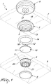
Figure 1 is an exploded perspective view of an embodiment of a pressure-operated closure device, according to the invention; -
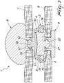
Figure 2 is a cross-sectional side view of the device ofFigure 1 , according to the invention, shown in the open configuration; -
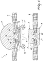
Figure 3 is a cross-sectional side view of the device ofFigure 1 , according to the invention, shown in the closed configuration; -
Figure 4 is an exploded perspective view of a variation of the pressure-operated closure device ofFigure 1 , according to the invention; -
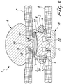
Figure 5 is a cross-sectional side view of the device ofFigure 4 , according to the invention, shown in the open configuration; -
Figure 6 is a cross-sectional side view of the device ofFigure 4 , according to the invention, shown in the closed configuration; -
Figure 7 shows a variation of a fixing element of the device inFigure 1 , according to the invention; -
Figure 8 shows a variation of a fixing element of the device ofFigure 4 , according to the invention; -
Figure 9 is a perspective view of the female component of a pressure-operated closure device, according to the invention. - With reference to the figures, the pressure-operated closure device, generally designated by the
reference numeral 1, comprises: - a
female element 2 in which acavity 3 is formed, - a
male element 4, which comprises alocking body 5 that is configured to be inserted into thecavity 3, - a first
complementary element 6 fixed to thefemale element 2 so as to retain afirst flap 7 of a fabric, - a second
complementary element 8 configured to be fixed to themale element 4 so as to retain asecond flap 9 of a fabric. - According to the invention, the
device 1 comprises afixing element 10 which comprises acap 11, which is visible through thecavity 3 of thefemale element 2, and fixing means 12. - The
cap 11 retains thefemale element 2, while the fixing means 12 fix thecap 11 and thefemale element 2 to the firstcomplementary element 6. - Advantageously therefore, the
first flap 7 of a fabric is arranged between thefemale element 2 and the firstcomplementary element 6. Thefixing element 10 passes through thefemale element 2 and thefirst flap 7 and enables the fixing of thefemale element 2 to the firstcomplementary element 6, by virtue of the retaining action carried out by thecap 11 and by the fixing means 12. - The
fixing element 10 substantially has the shape of a stud. - Advantageously, an
annular seat 13 is defined in thecavity 3 of thefemale element 2, which accommodates means 14 of elastic retention of thelocking body 5 of themale element 4. The elastic retention means 14 also have the function of keeping thecap 11 in thecavity 3. - This makes it possible to stably pre-assemble the
female element 2 to thefixing element 10 so as to be able to ship and distribute the set of the two components as a semi-finished product. - The elastic retention means 14 are advantageously constituted by a C-shaped retention spring.
- For the
locking device 1 to operate correctly, it is important that the retention means 14 are accommodated in theannular seat 13 with a tolerance that, on the one hand, allows the retention means 14 to expand during the step when thelocking body 5 is passing through, and which, on the other hand, prevents the retention means 5 from exiting from theannular seat 13. - The dimensions of the cap (11) are larger than the dimensions of the hole defined by the elastic retention means (14).
- As illustrated by way of example in
Figure 2 , thefixing element 10, and in particular thecap 11, is slightly larger than the passage hole defined by the C-shaped retention spring. - The
cap 11 has a slightly greater diameter than the diameter of the hole defined by the C-shaped retention spring. - In order to be capable of being inserted into the
cavity 3, thefixing element 10 slightly splays the spring, as indicated inFigure 2 by thearrows 25, and, once thecap 11 has passed through the spring, thefixing element 10 remains locked inside thecavity 3. - Advantageously the
cap 11, which has a surface appearance that can be seen through thecavity 3 of thefemale element 2, can be customized in terms of shapes, dimensions, tooling and materials according to the requirements of the purchaser. - For example, a commercial trademark can be printed on the
cap 11. - Advantageously the
cap 11 can have a flat visible surface appearance, or one that is convex, or one that is concave. - Advantageously the
female element 2 comprises a throughhole 15 which is passed through by the fixing means 12 of thefixing element 10. - As illustrated with reference to
Figures 1 ,2 and3 , the fixing means 12 can comprise apin 16 that is configured to be riveted inside afixing cavity 17 provided in the firstcomplementary element 6. - Alternatively, as illustrated in the variation of the
device 1 shown inFigures 4 ,5 and6 , the fixing means 12 can comprise afixing cavity 18 that is configured to receive apin 19 provided in the firstcomplementary element 6, thepin 19 being riveted inside thefixing cavity 18. - The
fixing element 10 can be provided in a single piece, or in two pieces assembled together, as shown inFigures 7 and 8 . - For example the
cap 11 can be fixed to the fixing means 12, i.e. to thepin 16 or to the walls that define thecavity 18, by folding its peripheral edge. - The elastic retention means 14 are advantageously adapted to engage an
undercut portion 20 of thelocking body 5 of themale element 4, in order to reversibly retain thelocking body 5 in thecavity 3 of thefemale element 2. - Advantageously the
male element 4 comprises apin 21 that is configured to be riveted inside afixing cavity 22 provided in the secondcomplementary element 8. - Alternatively, the fixing cavity can be provided in the
male element 4, while the pin can be present in the secondcomplementary element 8. - The present invention also relates to a female component for a pressure-operated
closure device 1 which comprises: - a
female element 2 in which acavity 3 is formed, - a first
complementary element 6 fixed to thefemale element 2 so as to retain afirst flap 7 of a fabric, - where the
fixing element 10 comprises acap 11, which is visible through thecavity 3 of thefemale element 2, and fixing means 12. Thecap 11 retains thefemale element 2, while the fixing means 12 fix thecap 11 and thefemale element 2 to the firstcomplementary element 6. - Advantageously the
female element 2 can be associated exclusively with the firstcomplementary element 6, with the elastic retention means 14 and with thefixing element 10. - In other words, the female component is advantageously constituted exclusively by the
female element 2, by the firstcomplementary element 6, by the elastic retention means 14 and by thefixing element 10. -
Figure 9 illustrates only the female component of the pressure-operated closure device, applied to aflap 7 of a fabric. Only thecap 11 is visible through thecavity 3 of thefemale element 2. The fixing means 12, i.e. pins and fixing cavities, are in fact covered from view by thecap 11. Thecap 11 can have, on the visible surface, a desired finish and/or decoration. - Operation of the pressure-operated closure device is clear and evident from the foregoing description.
- In practice it has been found that the pressure-operated closure device, according to the present invention, achieves the intended aim and objects since it makes it possible to eliminate the aesthetic drawbacks that afflict conventional pressure-operated closure devices.
- Another advantage of the device, according to the invention, consists in that it has components that can easily be assembled together according to conventional procedures.
- Another advantage of the device, according to the invention, consists in that it can be applied to items of clothing according to conventional procedures.
- Another advantage of the device, according to the invention, consists in that the fixing element provided with cap is pre-assembled to the female element, and therefore the female component of the device can be supplied to the end user ready to be applied to the fabric of the item of clothing.
- Another advantage of the pressure-operated closure device, according to the invention, consists in that the fixing of the female element to the respective complementary element, and the consequent retaining of the flap of fabric, are easy to implement and ensure an excellent stability of the female component on the fabric overall.
- The pressure-operated closure device thus conceived is susceptible of numerous modifications and variations, all of which are within the scope of the appended claims.
- Moreover, all the details may be substituted by other, technically equivalent elements.
- In practice the materials employed, provided they are compatible with the specific use, and the contingent dimensions and shapes, may be any according to requirements.
- Where technical features mentioned in any claim are followed by reference signs, those reference signs have been included for the sole purpose of increasing the intelligibility of the claims and accordingly, such reference signs do not have any limiting effect on the interpretation of each element identified by way of example by such reference signs.
Claims (7)
- A pressure-operated closure device (1), comprising:- a female element (2) in which a cavity (3) is formed,- a male element (4), which comprises a locking body (5) that is configured to be inserted into said cavity (3),- a first complementary element (6) fixed to said female element (2) so as to retain a first flap (7) of a fabric,- a second complementary element (8) configured to be fixed to said male element (4) so as to retain a second flap (9) of a fabric,
a fixing element (10) which comprises a cap (11), which is visible through said cavity (3) of said female element (2), and fixing means (12), said cap (11) retaining said female element (2), said fixing means (12) fixing said cap (11) and said female element (2) to said first complementary element (6), in said cavity (3) there being an annular seat (13) in which means (14) are accommodated for the elastic retention of said locking body (5) of said male element (4), said elastic retention means (14) retaining said cap (11) within said cavity (3), characterized in that said cap (11) of said fixing element (10) has greater dimensions than the dimensions of the hole defined by said elastic retention means (14). - The pressure-operated closure device (1) according to claim 1 , characterized in that said female element (2) comprises a through hole (15) which is passed through by said fixing means (12) of said fixing element (10).
- The pressure-operated closure device (1) according to claim 1 or 2, characterized in that said fixing means (12) comprise a pin (16) that is configured to be riveted inside a fixing cavity (17) provided in said first complementary element (6).
- The pressure-operated closure device (1) according to claims 1 or 2, characterized in that said fixing means (12) comprise a fixing cavity (18) that is configured to receive a pin (19) provided in said first complementary element (6), said pin (19) being riveted inside said fixing cavity (18).
- The pressure-operated closure device (1) according to one or more of the preceding claims, characterized in that said fixing element (10) is provided in a single piece.
- The pressure-operated closure device (1) according to one or more of claims 1 to 4, characterized in that said cap (11) is fixed to said fixing means (12) by bending the peripheral edge.
- The pressure-operated closure device (1) according to one or more of the preceding claims, characterized in that said elastic retention means (14) are adapted to engage an undercut portion (20) of said locking body (5) of said male element (4) in order to reversibly retain said locking body (5) of said male element (4) in said cavity (3) of said female element (2).
Applications Claiming Priority (1)
| Application Number | Priority Date | Filing Date | Title |
|---|---|---|---|
| IT102016000068993A IT201600068993A1 (en) | 2016-07-04 | 2016-07-04 | Pressure closing device. |
Publications (2)
| Publication Number | Publication Date |
|---|---|
| EP3266331A1 EP3266331A1 (en) | 2018-01-10 |
| EP3266331B1 true EP3266331B1 (en) | 2019-05-01 |
Family
ID=57609956
Family Applications (1)
| Application Number | Title | Priority Date | Filing Date |
|---|---|---|---|
| EP17178563.7A Active EP3266331B1 (en) | 2016-07-04 | 2017-06-29 | Pressure-operated closure device |
Country Status (3)
| Country | Link |
|---|---|
| EP (1) | EP3266331B1 (en) |
| ES (1) | ES2736405T3 (en) |
| IT (1) | IT201600068993A1 (en) |
Family Cites Families (4)
| Publication number | Priority date | Publication date | Assignee | Title |
|---|---|---|---|---|
| US1897936A (en) * | 1931-12-05 | 1933-02-14 | Ben Z Hausner | Snap fastener |
| FR995414A (en) * | 1945-02-28 | 1951-12-03 | Brev Et Licences Pour Applic M | Improvements to push button stapling systems |
| US2546716A (en) * | 1947-03-25 | 1951-03-27 | United Carr Fastener Corp | Separable snap fastener type socket member |
| JP5132490B2 (en) * | 2008-09-04 | 2013-01-30 | Ykk株式会社 | Male snap |
-
2016
- 2016-07-04 IT IT102016000068993A patent/IT201600068993A1/en unknown
-
2017
- 2017-06-29 EP EP17178563.7A patent/EP3266331B1/en active Active
- 2017-06-29 ES ES17178563T patent/ES2736405T3/en active Active
Non-Patent Citations (1)
| Title |
|---|
| None * |
Also Published As
| Publication number | Publication date |
|---|---|
| ES2736405T3 (en) | 2019-12-30 |
| EP3266331A1 (en) | 2018-01-10 |
| IT201600068993A1 (en) | 2018-01-04 |
Similar Documents
| Publication | Publication Date | Title |
|---|---|---|
| EP3216363B1 (en) | Die-cast snap button | |
| EP2737816B1 (en) | Pressure snap fastener with a bivalent closure | |
| US9474337B2 (en) | Female component of a press stud, a method for the manufacture thereof, and a press stud including this female component | |
| US20110016679A1 (en) | Press stud | |
| EP3219219A1 (en) | Assembly-type decoration | |
| JP2019517875A (en) | System for reversibly securing decorative trims on the surface of a leather craft article made of flexible material | |
| US3449802A (en) | Trim button | |
| EP3266331B1 (en) | Pressure-operated closure device | |
| CN109661186B (en) | Buckle and belt having the same | |
| US3333306A (en) | Capped eyelet for attaching snap fasteners | |
| US10925352B2 (en) | Button assembly with removable cap | |
| KR101632531B1 (en) | Buckle device | |
| JP2008036337A (en) | Hook | |
| WO2012173475A1 (en) | System comprising a button, an attaching member and a decorative element, as well as a button or a decorative element as part of this system and a garment provided with such a button | |
| US1654479A (en) | Slide button | |
| US2648882A (en) | Removable button member | |
| US1223146A (en) | Turn-button fastener. | |
| US2622299A (en) | Plastic cap for attachment of snap fastener sockets and the like | |
| US1612943A (en) | Snap fastener | |
| US626744A (en) | Button | |
| US2832117A (en) | Covered button | |
| US1835948A (en) | Combined ornamental and attaching member | |
| US118640A (en) | Improvement in eyelets for attaching buttons to textile fabrics | |
| EP3585205B1 (en) | Coupling element and coupling system comprising said coupling element | |
| US1289493A (en) | Garment and other fastener. |
Legal Events
| Date | Code | Title | Description |
|---|---|---|---|
| PUAI | Public reference made under article 153(3) epc to a published international application that has entered the european phase |
Free format text: ORIGINAL CODE: 0009012 |
|
| STAA | Information on the status of an ep patent application or granted ep patent |
Free format text: STATUS: THE APPLICATION HAS BEEN PUBLISHED |
|
| AK | Designated contracting states |
Kind code of ref document: A1 Designated state(s): AL AT BE BG CH CY CZ DE DK EE ES FI FR GB GR HR HU IE IS IT LI LT LU LV MC MK MT NL NO PL PT RO RS SE SI SK SM TR |
|
| AX | Request for extension of the european patent |
Extension state: BA ME |
|
| STAA | Information on the status of an ep patent application or granted ep patent |
Free format text: STATUS: REQUEST FOR EXAMINATION WAS MADE |
|
| 17P | Request for examination filed |
Effective date: 20180706 |
|
| RBV | Designated contracting states (corrected) |
Designated state(s): AL AT BE BG CH CY CZ DE DK EE ES FI FR GB GR HR HU IE IS IT LI LT LU LV MC MK MT NL NO PL PT RO RS SE SI SK SM TR |
|
| GRAP | Despatch of communication of intention to grant a patent |
Free format text: ORIGINAL CODE: EPIDOSNIGR1 |
|
| STAA | Information on the status of an ep patent application or granted ep patent |
Free format text: STATUS: GRANT OF PATENT IS INTENDED |
|
| INTG | Intention to grant announced |
Effective date: 20181116 |
|
| GRAS | Grant fee paid |
Free format text: ORIGINAL CODE: EPIDOSNIGR3 |
|
| GRAA | (expected) grant |
Free format text: ORIGINAL CODE: 0009210 |
|
| STAA | Information on the status of an ep patent application or granted ep patent |
Free format text: STATUS: THE PATENT HAS BEEN GRANTED |
|
| AK | Designated contracting states |
Kind code of ref document: B1 Designated state(s): AL AT BE BG CH CY CZ DE DK EE ES FI FR GB GR HR HU IE IS IT LI LT LU LV MC MK MT NL NO PL PT RO RS SE SI SK SM TR |
|
| REG | Reference to a national code |
Ref country code: GB Ref legal event code: FG4D |
|
| REG | Reference to a national code |
Ref country code: CH Ref legal event code: EP Ref country code: AT Ref legal event code: REF Ref document number: 1125746 Country of ref document: AT Kind code of ref document: T Effective date: 20190515 |
|
| REG | Reference to a national code |
Ref country code: DE Ref legal event code: R096 Ref document number: 602017003612 Country of ref document: DE |
|
| REG | Reference to a national code |
Ref country code: IE Ref legal event code: FG4D |
|
| REG | Reference to a national code |
Ref country code: NL Ref legal event code: MP Effective date: 20190501 |
|
| REG | Reference to a national code |
Ref country code: LT Ref legal event code: MG4D |
|
| PG25 | Lapsed in a contracting state [announced via postgrant information from national office to epo] |
Ref country code: NO Free format text: LAPSE BECAUSE OF FAILURE TO SUBMIT A TRANSLATION OF THE DESCRIPTION OR TO PAY THE FEE WITHIN THE PRESCRIBED TIME-LIMIT Effective date: 20190801 Ref country code: LT Free format text: LAPSE BECAUSE OF FAILURE TO SUBMIT A TRANSLATION OF THE DESCRIPTION OR TO PAY THE FEE WITHIN THE PRESCRIBED TIME-LIMIT Effective date: 20190501 Ref country code: FI Free format text: LAPSE BECAUSE OF FAILURE TO SUBMIT A TRANSLATION OF THE DESCRIPTION OR TO PAY THE FEE WITHIN THE PRESCRIBED TIME-LIMIT Effective date: 20190501 Ref country code: SE Free format text: LAPSE BECAUSE OF FAILURE TO SUBMIT A TRANSLATION OF THE DESCRIPTION OR TO PAY THE FEE WITHIN THE PRESCRIBED TIME-LIMIT Effective date: 20190501 Ref country code: HR Free format text: LAPSE BECAUSE OF FAILURE TO SUBMIT A TRANSLATION OF THE DESCRIPTION OR TO PAY THE FEE WITHIN THE PRESCRIBED TIME-LIMIT Effective date: 20190501 Ref country code: AL Free format text: LAPSE BECAUSE OF FAILURE TO SUBMIT A TRANSLATION OF THE DESCRIPTION OR TO PAY THE FEE WITHIN THE PRESCRIBED TIME-LIMIT Effective date: 20190501 Ref country code: PT Free format text: LAPSE BECAUSE OF FAILURE TO SUBMIT A TRANSLATION OF THE DESCRIPTION OR TO PAY THE FEE WITHIN THE PRESCRIBED TIME-LIMIT Effective date: 20190901 Ref country code: NL Free format text: LAPSE BECAUSE OF FAILURE TO SUBMIT A TRANSLATION OF THE DESCRIPTION OR TO PAY THE FEE WITHIN THE PRESCRIBED TIME-LIMIT Effective date: 20190501 |
|
| PG25 | Lapsed in a contracting state [announced via postgrant information from national office to epo] |
Ref country code: BG Free format text: LAPSE BECAUSE OF FAILURE TO SUBMIT A TRANSLATION OF THE DESCRIPTION OR TO PAY THE FEE WITHIN THE PRESCRIBED TIME-LIMIT Effective date: 20190801 Ref country code: RS Free format text: LAPSE BECAUSE OF FAILURE TO SUBMIT A TRANSLATION OF THE DESCRIPTION OR TO PAY THE FEE WITHIN THE PRESCRIBED TIME-LIMIT Effective date: 20190501 Ref country code: LV Free format text: LAPSE BECAUSE OF FAILURE TO SUBMIT A TRANSLATION OF THE DESCRIPTION OR TO PAY THE FEE WITHIN THE PRESCRIBED TIME-LIMIT Effective date: 20190501 Ref country code: GR Free format text: LAPSE BECAUSE OF FAILURE TO SUBMIT A TRANSLATION OF THE DESCRIPTION OR TO PAY THE FEE WITHIN THE PRESCRIBED TIME-LIMIT Effective date: 20190802 |
|
| REG | Reference to a national code |
Ref country code: AT Ref legal event code: MK05 Ref document number: 1125746 Country of ref document: AT Kind code of ref document: T Effective date: 20190501 |
|
| REG | Reference to a national code |
Ref country code: ES Ref legal event code: FG2A Ref document number: 2736405 Country of ref document: ES Kind code of ref document: T3 Effective date: 20191230 |
|
| PG25 | Lapsed in a contracting state [announced via postgrant information from national office to epo] |
Ref country code: IS Free format text: LAPSE BECAUSE OF FAILURE TO SUBMIT A TRANSLATION OF THE DESCRIPTION OR TO PAY THE FEE WITHIN THE PRESCRIBED TIME-LIMIT Effective date: 20190901 |
|
| PG25 | Lapsed in a contracting state [announced via postgrant information from national office to epo] |
Ref country code: SK Free format text: LAPSE BECAUSE OF FAILURE TO SUBMIT A TRANSLATION OF THE DESCRIPTION OR TO PAY THE FEE WITHIN THE PRESCRIBED TIME-LIMIT Effective date: 20190501 Ref country code: MC Free format text: LAPSE BECAUSE OF FAILURE TO SUBMIT A TRANSLATION OF THE DESCRIPTION OR TO PAY THE FEE WITHIN THE PRESCRIBED TIME-LIMIT Effective date: 20190501 Ref country code: AT Free format text: LAPSE BECAUSE OF FAILURE TO SUBMIT A TRANSLATION OF THE DESCRIPTION OR TO PAY THE FEE WITHIN THE PRESCRIBED TIME-LIMIT Effective date: 20190501 Ref country code: DK Free format text: LAPSE BECAUSE OF FAILURE TO SUBMIT A TRANSLATION OF THE DESCRIPTION OR TO PAY THE FEE WITHIN THE PRESCRIBED TIME-LIMIT Effective date: 20190501 Ref country code: EE Free format text: LAPSE BECAUSE OF FAILURE TO SUBMIT A TRANSLATION OF THE DESCRIPTION OR TO PAY THE FEE WITHIN THE PRESCRIBED TIME-LIMIT Effective date: 20190501 Ref country code: RO Free format text: LAPSE BECAUSE OF FAILURE TO SUBMIT A TRANSLATION OF THE DESCRIPTION OR TO PAY THE FEE WITHIN THE PRESCRIBED TIME-LIMIT Effective date: 20190501 Ref country code: CZ Free format text: LAPSE BECAUSE OF FAILURE TO SUBMIT A TRANSLATION OF THE DESCRIPTION OR TO PAY THE FEE WITHIN THE PRESCRIBED TIME-LIMIT Effective date: 20190501 |
|
| REG | Reference to a national code |
Ref country code: DE Ref legal event code: R097 Ref document number: 602017003612 Country of ref document: DE |
|
| PG25 | Lapsed in a contracting state [announced via postgrant information from national office to epo] |
Ref country code: SM Free format text: LAPSE BECAUSE OF FAILURE TO SUBMIT A TRANSLATION OF THE DESCRIPTION OR TO PAY THE FEE WITHIN THE PRESCRIBED TIME-LIMIT Effective date: 20190501 |
|
| PLBE | No opposition filed within time limit |
Free format text: ORIGINAL CODE: 0009261 |
|
| STAA | Information on the status of an ep patent application or granted ep patent |
Free format text: STATUS: NO OPPOSITION FILED WITHIN TIME LIMIT |
|
| REG | Reference to a national code |
Ref country code: BE Ref legal event code: MM Effective date: 20190630 |
|
| PG25 | Lapsed in a contracting state [announced via postgrant information from national office to epo] |
Ref country code: TR Free format text: LAPSE BECAUSE OF FAILURE TO SUBMIT A TRANSLATION OF THE DESCRIPTION OR TO PAY THE FEE WITHIN THE PRESCRIBED TIME-LIMIT Effective date: 20190501 |
|
| 26N | No opposition filed |
Effective date: 20200204 |
|
| PG25 | Lapsed in a contracting state [announced via postgrant information from national office to epo] |
Ref country code: PL Free format text: LAPSE BECAUSE OF FAILURE TO SUBMIT A TRANSLATION OF THE DESCRIPTION OR TO PAY THE FEE WITHIN THE PRESCRIBED TIME-LIMIT Effective date: 20190501 Ref country code: IE Free format text: LAPSE BECAUSE OF NON-PAYMENT OF DUE FEES Effective date: 20190629 |
|
| PG25 | Lapsed in a contracting state [announced via postgrant information from national office to epo] |
Ref country code: SI Free format text: LAPSE BECAUSE OF FAILURE TO SUBMIT A TRANSLATION OF THE DESCRIPTION OR TO PAY THE FEE WITHIN THE PRESCRIBED TIME-LIMIT Effective date: 20190501 Ref country code: LU Free format text: LAPSE BECAUSE OF NON-PAYMENT OF DUE FEES Effective date: 20190629 Ref country code: BE Free format text: LAPSE BECAUSE OF NON-PAYMENT OF DUE FEES Effective date: 20190630 |
|
| REG | Reference to a national code |
Ref country code: CH Ref legal event code: PL |
|
| PG25 | Lapsed in a contracting state [announced via postgrant information from national office to epo] |
Ref country code: LI Free format text: LAPSE BECAUSE OF NON-PAYMENT OF DUE FEES Effective date: 20200630 Ref country code: CH Free format text: LAPSE BECAUSE OF NON-PAYMENT OF DUE FEES Effective date: 20200630 |
|
| PG25 | Lapsed in a contracting state [announced via postgrant information from national office to epo] |
Ref country code: CY Free format text: LAPSE BECAUSE OF FAILURE TO SUBMIT A TRANSLATION OF THE DESCRIPTION OR TO PAY THE FEE WITHIN THE PRESCRIBED TIME-LIMIT Effective date: 20190501 |
|
| PG25 | Lapsed in a contracting state [announced via postgrant information from national office to epo] |
Ref country code: MT Free format text: LAPSE BECAUSE OF FAILURE TO SUBMIT A TRANSLATION OF THE DESCRIPTION OR TO PAY THE FEE WITHIN THE PRESCRIBED TIME-LIMIT Effective date: 20190501 Ref country code: HU Free format text: LAPSE BECAUSE OF FAILURE TO SUBMIT A TRANSLATION OF THE DESCRIPTION OR TO PAY THE FEE WITHIN THE PRESCRIBED TIME-LIMIT; INVALID AB INITIO Effective date: 20170629 |
|
| PG25 | Lapsed in a contracting state [announced via postgrant information from national office to epo] |
Ref country code: MK Free format text: LAPSE BECAUSE OF FAILURE TO SUBMIT A TRANSLATION OF THE DESCRIPTION OR TO PAY THE FEE WITHIN THE PRESCRIBED TIME-LIMIT Effective date: 20190501 |
|
| P01 | Opt-out of the competence of the unified patent court (upc) registered |
Effective date: 20230528 |
|
| PGFP | Annual fee paid to national office [announced via postgrant information from national office to epo] |
Ref country code: IT Payment date: 20230612 Year of fee payment: 7 Ref country code: FR Payment date: 20230623 Year of fee payment: 7 Ref country code: DE Payment date: 20230606 Year of fee payment: 7 |
|
| PGFP | Annual fee paid to national office [announced via postgrant information from national office to epo] |
Ref country code: GB Payment date: 20230517 Year of fee payment: 7 Ref country code: ES Payment date: 20230703 Year of fee payment: 7 |